SASE Cisco

SASE | SASE Solution

SASE Solution

In the realm of network security, the rise of SASE (Secure Access Service Edge) solution has been nothing short of revolutionary. Combining the capabilities of networking and security into a single cloud-based service, SASE has transformed the way organizations manage and protect their digital infrastructure. In this blog post, we will explore the key components and benefits of SASE, shedding light on how it is reshaping the landscape of network security.

SASE, an acronym for Secure Access Service Edge, is a comprehensive framework that converges network and security services into a unified cloud-native architecture. By merging wide area networking (WAN) and network security functions, SASE enables organizations to simplify their infrastructure while enhancing security and performance. This convergence is achieved through the integration of various technologies such as SD-WAN (Software-Defined Wide Area Networking), firewall-as-a-service, secure web gateways, and more.

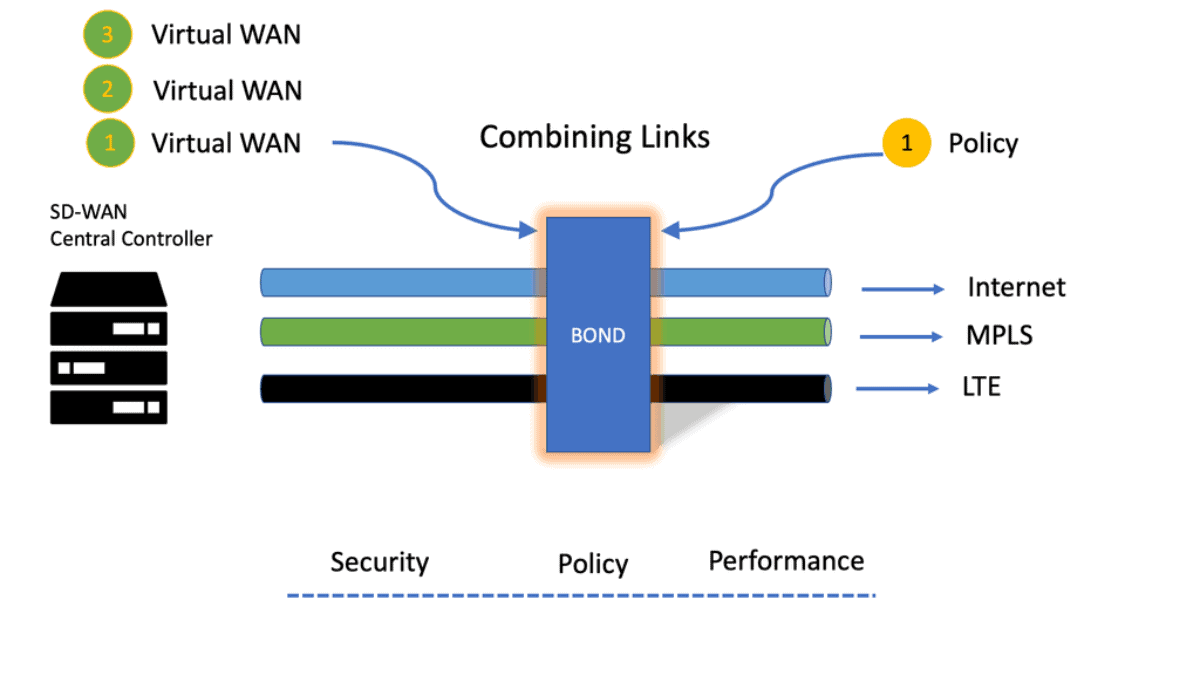
SD-WAN: SD-WAN technology lies at the heart of SASE, providing agile and scalable connectivity across geographically dispersed locations. It offers centralized management, intelligent traffic routing, and dynamic path selection, optimizing network performance and reliability.

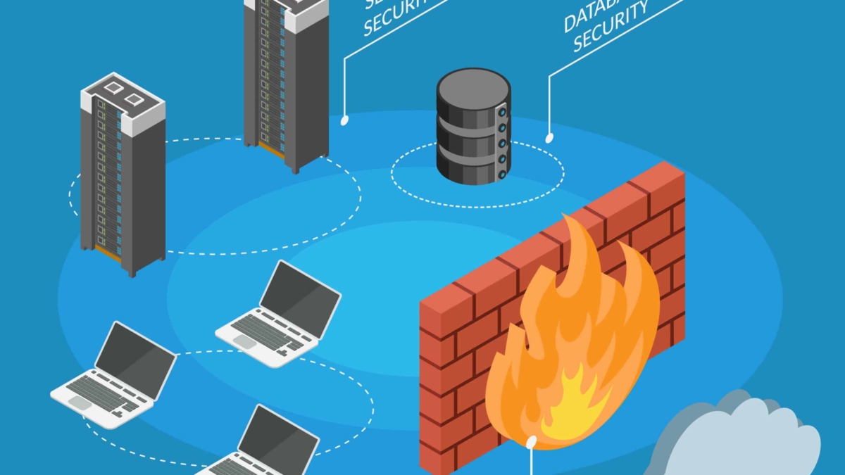
Cloud-native Security: SASE leverages cloud-native security services, including firewall-as-a-service (FWaaS), secure web gateways (SWG), data loss prevention (DLP), and zero-trust network access (ZTNA). These services are delivered from the cloud, ensuring consistent and robust security across the entire network infrastructure.

Identity-Centric Access: SASE incorporates an identity-centric approach to access control, focusing on user identity rather than network location. With zero-trust principles, SASE ensures that only authorized users and devices can access the network, regardless of their location or network connection.

Benefits of SASE
Simplified Infrastructure: SASE eliminates the need for multiple point solutions by consolidating networking and security into a single cloud-based service. This simplification reduces complexity, streamlines operations, and lowers costs associated with managing disparate security tools.

Enhanced Security: With its cloud-native security services, SASE provides advanced threat protection, real-time monitoring, and granular access control. This ensures that organizations can defend against emerging threats while maintaining compliance with industry regulations.

Improved Performance: SASE leverages SD-WAN technology to optimize network traffic, enabling faster and more reliable connectivity. By dynamically routing traffic based on application and network conditions, SASE minimizes latency and maximizes performance for end-users.

The emergence of SASE solution has revolutionized network security by converging networking and security services into a unified cloud-native architecture. With its key components such as SD-WAN, cloud-native security, and identity-centric access, SASE offers simplified infrastructure, enhanced security, and improved performance for organizations of all sizes.

As the digital landscape continues to evolve, embracing the power of SASE becomes imperative to stay resilient against ever-evolving cyber threats and ensure seamless connectivity across the network.

Highlights: SASE Solution

What is SASE?

SASE, which stands for Secure Access Service Edge, is an innovative networking architecture that combines network security and wide-area networking (WAN) capabilities into a unified cloud-based solution. It shifts networking and security functionalities to the cloud, eliminating the need for traditional hardware-centric approaches. By converging these services, SASE offers a holistic and scalable solution that adapts to the ever-evolving demands of modern businesses.

**The Core Components of SASE**

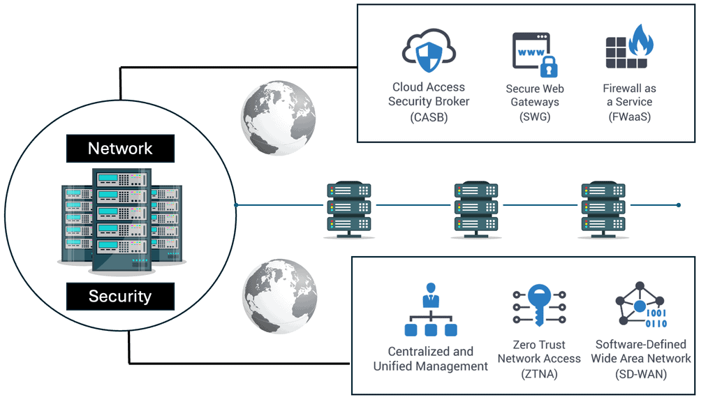
SASE integrates several key technologies to deliver its promise of seamless security and connectivity. At its core, SASE combines Software-Defined Wide Area Networking (SD-WAN) with robust security services such as Secure Web Gateways (SWG), Cloud Access Security Brokers (CASB), Firewall as a Service (FWaaS), and Zero Trust Network Access (ZTNA). This convergence allows organizations to simplify their IT infrastructure, reduce costs, and enhance security posture by delivering network and security functions from the cloud.

**Benefits of Adopting SASE**

Organizations that adopt SASE can experience a multitude of benefits. Firstly, SASE offers improved performance by leveraging the cloud’s scalability, ensuring users experience low latency and high-speed connections regardless of location. Secondly, the unified approach to security reduces complexity, enabling IT teams to manage policies across all users and devices from a single platform. Lastly, SASE enhances security by applying consistent and context-aware security policies, thus reducing vulnerabilities and potential breaches.

**Challenges and Considerations**

While SASE presents numerous advantages, organizations must also consider potential challenges. Transitioning to a SASE framework requires careful planning and execution, as it involves re-architecting existing network and security infrastructures. Additionally, choosing the right SASE provider is crucial, as the quality and range of services can vary significantly. Organizations must evaluate providers based on their ability to deliver comprehensive security features, global reach, and reliability.

SASE Key Points:

1. Enhanced Security: SASE provides robust security measures, such as integrated firewalling, data loss prevention, and secure web gateways, to safeguard networks and data from emerging threats. Organizations can streamline their security operations and reduce complexity with a unified security framework.

2. Improved Performance: SASE optimizes network performance and minimizes latency by leveraging cloud-native infrastructure. It enables efficient traffic routing, intelligent application steering, and dynamic bandwidth allocation, ensuring a seamless user experience even in geographically dispersed environments.

3. Simplified Network Management: Traditional networking architectures often involve managing multiple vendors and complex configurations. SASE simplifies network management through centralized policy-based controls and automation, reducing administrative overhead and enhancing operational efficiency.
Adopting a SASE Solution:

By adopting a SASE solution, businesses can unlock a plethora of benefits. Firstly, it provides secure access to applications and data from any location, enabling seamless remote work capabilities. Additionally, SASE eliminates the need for traditional hardware-based security appliances, reducing costs and complexity. The centralized management and policy enforcement offered by SASE ensures consistent security across the entire network, regardless of the user’s location or device.

**Adopt a Phased Approach**

While the benefits of SASE are enticing, organizations must approach its implementation strategically. Assessing the existing network infrastructure, defining security requirements, and selecting a reliable SASE provider is crucial. A phased approach to performance, starting with pilot projects and gradually scaling up, can help organizations ensure a smooth transition and maximize the potential of SASE.

**SASE Components**

Understanding its key components is essential to fully grasping the power of SASE. These include secure web gateways (SWG), cloud access security brokers (CASB), firewall-as-a-service (FWaaS), data loss prevention (DLP), and zero-trust network access (ZTNA). Each element is crucial in fortifying network security while enabling seamless user connectivity.

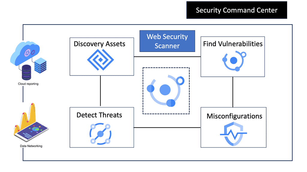
Example SASE Technology: Web Security Scanner

**What are Web Security Scanners?**

Web security scanners are automated tools designed to identify security vulnerabilities within web applications. They simulate cyber-attacks to detect weaknesses that malicious hackers might exploit. These tools scan for various vulnerabilities like SQL injection, cross-site scripting (XSS), and insecure server configurations. By identifying these weaknesses, web security scanners enable businesses to proactively address potential threats before they can be exploited.

**The Role of Google Cloud in Enhancing Web Security**

Google Cloud offers a comprehensive suite of security tools and services that complement web security scanners. By integrating these scanners with Google Cloud, businesses can leverage advanced analytics and machine learning capabilities to enhance their security posture. Google Cloud’s global infrastructure ensures high availability and scalability, allowing security scanners to operate efficiently across large-scale applications.
**Benefits of Using Web Security Scanners on Google Cloud**

1. **Automated Vulnerability Detection**: Web security scanners automate the process of identifying vulnerabilities, reducing the time and effort required for manual testing. This automation ensures that potential threats are detected quickly and efficiently.

2. **Scalability and Performance**: Google Cloud’s infrastructure supports the scalability of web security scanners, allowing them to handle large volumes of data without compromising performance. This scalability is crucial for businesses with extensive web applications.

3. **Integrated Security Solutions**: Google Cloud offers a range of integrated security solutions, including Identity and Access Management (IAM) and Security Command Center, which complement the capabilities of web security scanners. These solutions provide a holistic approach to securing web applications.

**Real-World Applications: Case Studies**

Several organizations have successfully implemented web security scanners on Google Cloud to enhance their security measures. For instance, a leading e-commerce company utilized these tools to identify and remediate vulnerabilities in their payment gateway, safeguarding customer transactions. Similarly, a healthcare provider leveraged Google Cloud’s security services to protect patient data, ensuring compliance with stringent regulations.

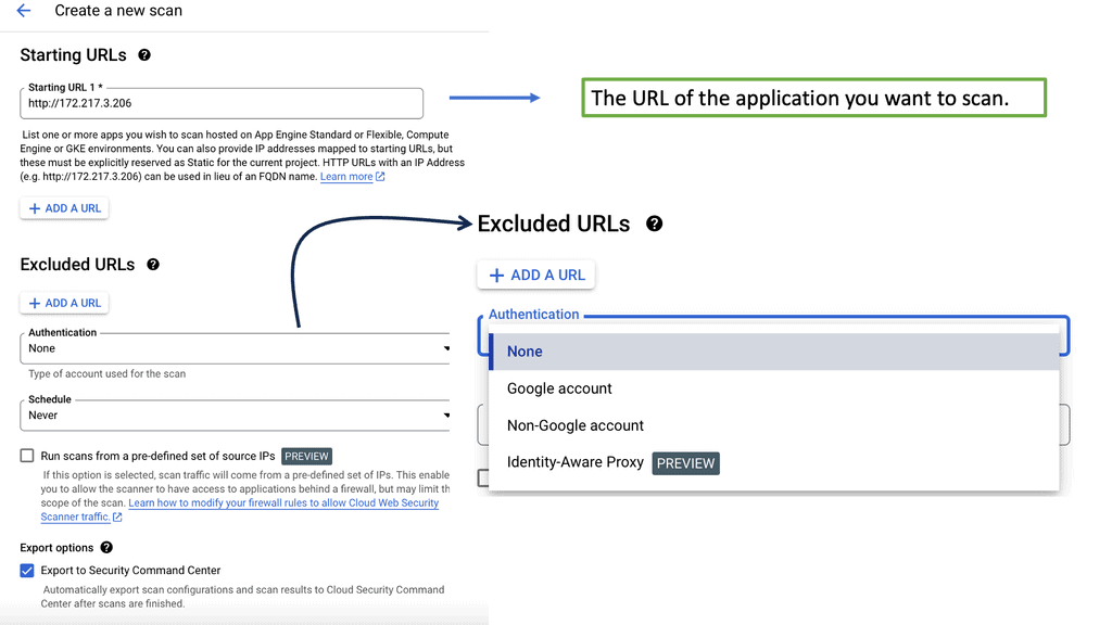
security web scanner Zero Trust & Identity

The path to zero trust starts with identity. Network access is based on the identity of the user, the device, and the application, not on the device’s IP address or physical location. And this is for a good reason. There needs to be contextual information.

a) User & Device Identity

The user/device’s identity must reflect the business context instead of being associated with binary constructs utterly disjointed from the upper layers. This binds an identity to the networking world and is the best way forward for policy enforcement.

b) Lack of Good Identifiers

Therefore, the dependency on IP or applications as identifiers is removed. Now, the policy is applied consistently regardless of where the user/device is located, while the identity of the user/device/service can be factored into the policy. The SASE stack is dynamically applied based on originality and context while serving zero trust at strategic points in the cloud, enforcing an identity-centric perimeter.

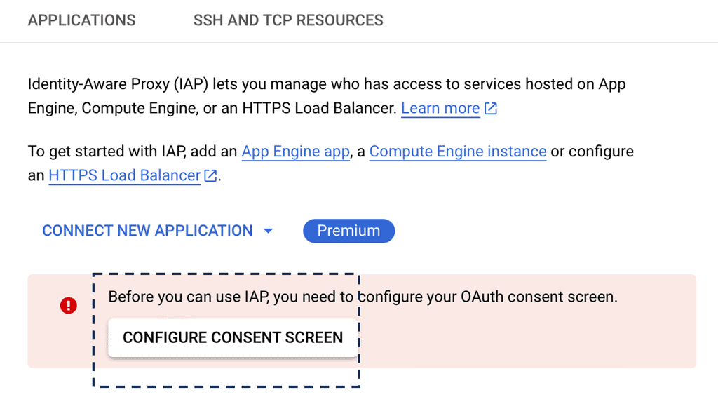
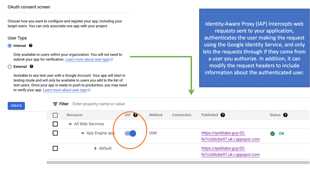
Example Identity Technology: Identity Aware Proxy 
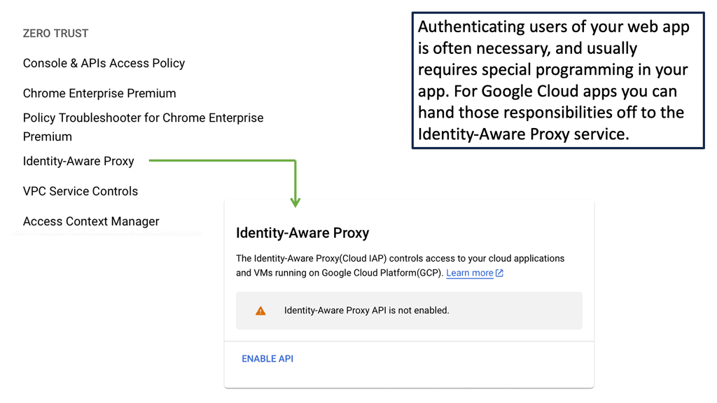
Identity aware proxy

c) The Role of SASE Security

In this post, we will decompose the Zero Trust SASE, considering the SASE fabric and what a SASE solution entails. The SASE security consists of global PoPs. With network and security functions built into each PoP, they are operated with a single management plane. This post will examine the fabric components while discussing the generic networking and security challenges that SASE overcomes, focusing on Cisco SASE.

**Example SASE Solution – Cisco Approach: CSP 5000 & NFV**

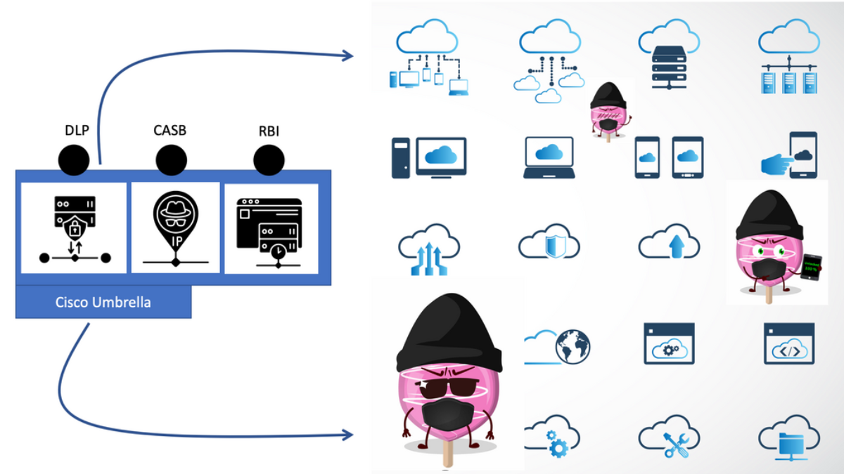
The Cisco SASE definition is often deemed just Cisco Umbrella; however, that is just part of the solution. Cisco SASE includes the Umbrella but entails an entirely new architecture based on the CSP 5000 and Network Function Virtualization (NFV) and a series of Virtual Network Functions (VNFs) such as virtual firewalls. We will touch on Cisco SASE soon.

As the SASE solution has many dependencies, you, as an enterprise, know how far you are in your cloud adoption. Whether you are a public cloud first, hybrid, multi, or private cloud path affects the design of your DMZ. SASE security is all about optimizing the DMZ to enable secure methods.

Related: For pre-information, you may find the following posts helpful:

  1. SD-WAN SASE
  2. SASE Model
  3. Cisco Secure Firewall
  4. Ebook on SASE Capabilities

SASE Solution

SASE – Cloud-based 

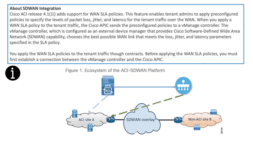
SASE directs to a concept incorporating cloud-based software-defined wide area networking (SD-WAN) with a range of security services and unified management functionality for delivering security and SD-WAN capabilities to any edge computing location. A prime use case for SASE is to address the performance bottleneck issues of traditional networks that rely on traffic backhauling. Further, by integrating identity, business context, and real-time risk assessment into every connection, SASE architectures pledge to control a variety of cyber-attacks.
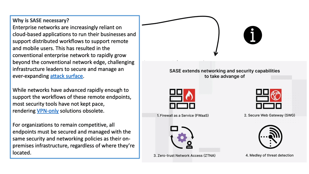
SASE explained
Diagram: SASE explained. Source Fortinet.

The DMZ: Calling a SASE Solution

**Updating the DMZ**

First, the SASE architecture updates the DMZ, which has remained unchanged since the mid-90s. The DMZ, often called the perimeter network, is a physical or logical subnetwork whose sole purpose is to expose an organization’s external-facing services to untrusted networks.

The DMZ adds a layer of security so that potentially insecure external networks can only access what is exposed in the DMZ. At the same time, the rest of the organization’s network is protected by a security stack.

**Extra Time But that’s about it**

As a result, the DMZ is considered a small, isolated network portion and, if configured correctly, will give you extra time to detect and address breaches, malware, and other types of attacks before they further penetrate the internal networks. 

The critical factor here is that it’s a layer that, at best, gives you additional time before the breach to the internal network. The central pain point with the current DMZ architecture is that the bad actor knows it’s there unless you opt for zero trust single packet authentication or some other zero-trust technology. 

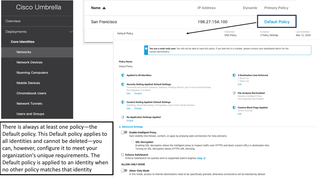
Example Product: Cisco Umbrella & DNS Layer Security 
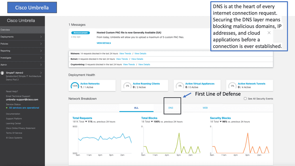
Key Note: SASE security and SD-WAN

This is similar to updating the WAN edge with SD-WAN to optimize performance per application with SDWAN overlays. Both SASE and SD-WAN are updating, let’s say, the last hardware bastions in your infrastructure: SD-WAN with the WAN edge and SASE with the DMZ. 

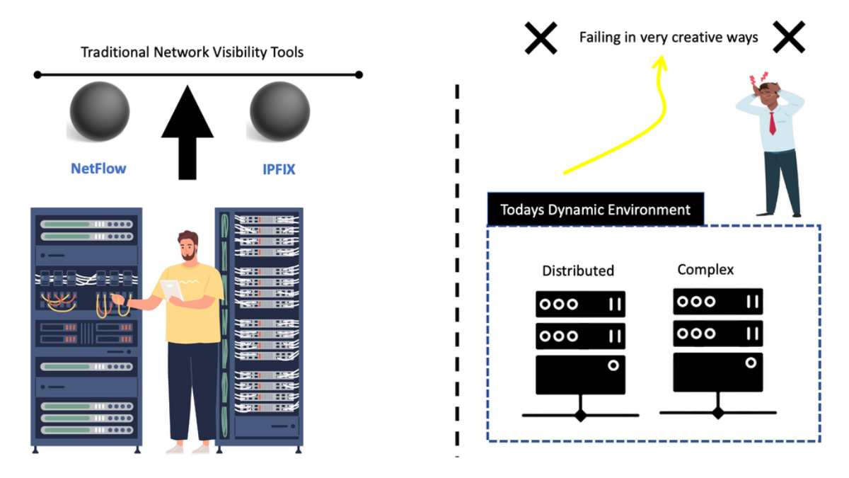
The DMZ is a vital section, but it needs to be secure from a perimeter firewall with a port and our traffic flow. It also needs good visibility, the ability to detect and attack, and respond appropriately, and quick reaction time—speeds achievable only with secure automation.

A Perfect DMZ: SASE Solution

  • Support API and Modeling Languages

These new DMZ designs need to be open. It must support API and open standard modeling languages like XML and YANG. This will allow you to support various network and security devices, physical, virtual, and hybrid, via secure API. Not only does it need to be open, but it also needs to be extensible and repeatable. So, we can allow new functionality to be added and removed as the architecture evolves and react to dynamic business objectives.

  • Scalability with NFV

SASE also needs to scale up and down, out and in, with little or no disruption to existing services. It should be able to scale without adding physical appliances, as physical devices can only scale so far. The SASE solution needs Network Function Virtualization ( NFV ) with a series of Virtual Network Functions (VNFs) chained together. Cisco CSP 5000 can be used here, and we will discuss it briefly.

  • Orchestration & Automation

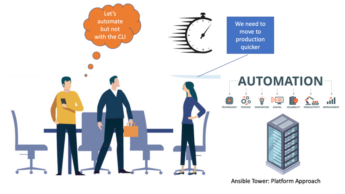
You want to avoid dealing with the device’s CLI. The new SASE fabric needs to be well-programmable. All functional elements of the architecture are fully programmable via API.

The APIs cannot just read data but can change behavior, such as network device configurations. So you will need an orchestrator for this. For example, Ansible Tower could automate and manage configuration drift among the virtual network functions. Ansible Tower provides end-to-end team automation with features such as workflow templates and integration into the CI/CD pipelines.

SASE Security & SDN

Network segmentation is essential to segment the data and control plane traffic. So, the control plane configures the devices, and the data plane forwards the traffic. The segmentation aspect is sufficient for the scalability and performance of resolutions. To manage SASE security, you will need to employ software-defined networking principles. The SDN controller is not in the forward path. It just sets up the data plane. The data plane should operate even if the control plane fails. However, the control plane could have some clustering to avoid failure.

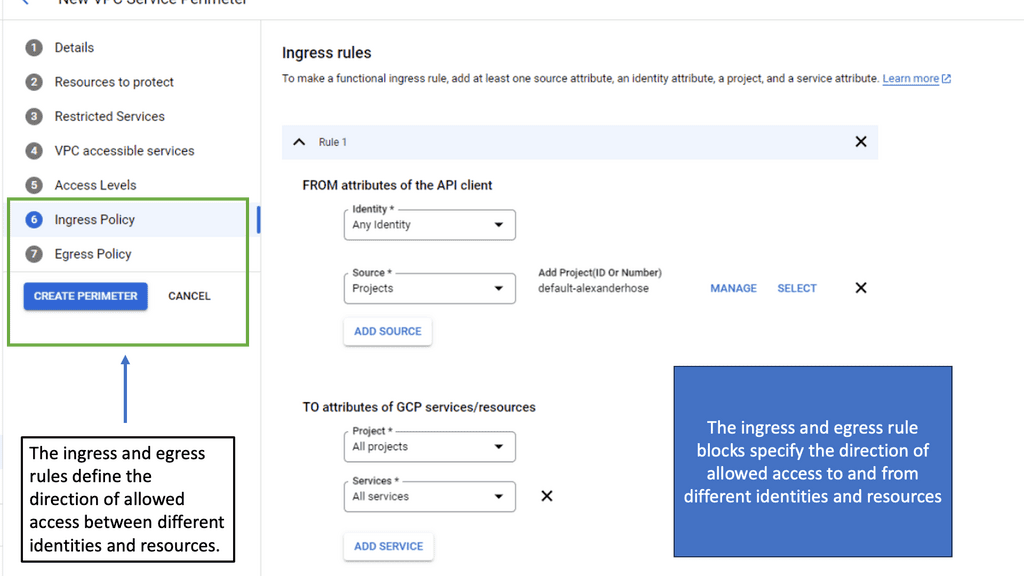
Example: Software Defined Perimeter (SDP)

**Understanding the Basics of VPC Service Controls**

VPC Service Controls are designed to augment the security of Google Cloud services by establishing a security perimeter around your cloud resources. This means that even if a malicious actor gains access to your network, they won’t be able to exfiltrate data outside the defined boundaries. This section will delve into the fundamental components of VPC Service Controls, including service perimeters, access levels, and policy configurations. We’ll also touch on how these controls integrate with other Google Cloud security features to provide a comprehensive security framework.

**Implementing VPC Service Controls: Step-by-Step Guide**

Setting up VPC Service Controls can seem daunting, but with a structured approach, it becomes manageable. This section outlines a step-by-step guide to implementing VPC Service Controls on Google Cloud. From defining your service perimeter to configuring access levels and monitoring the setup, we’ll provide practical insights and best practices. Additionally, we’ll discuss common pitfalls and how to avoid them, ensuring a smooth and efficient configuration process.
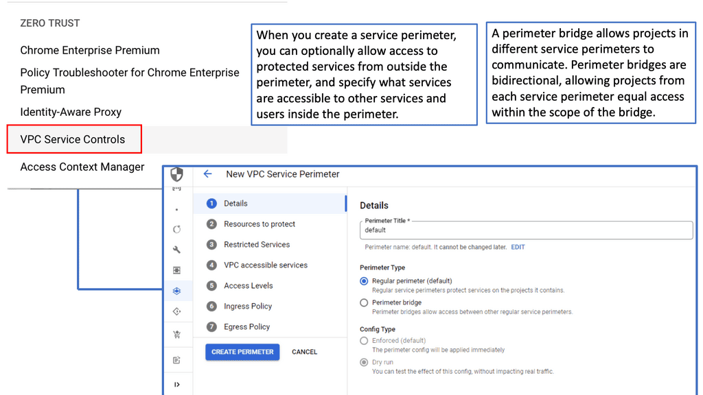
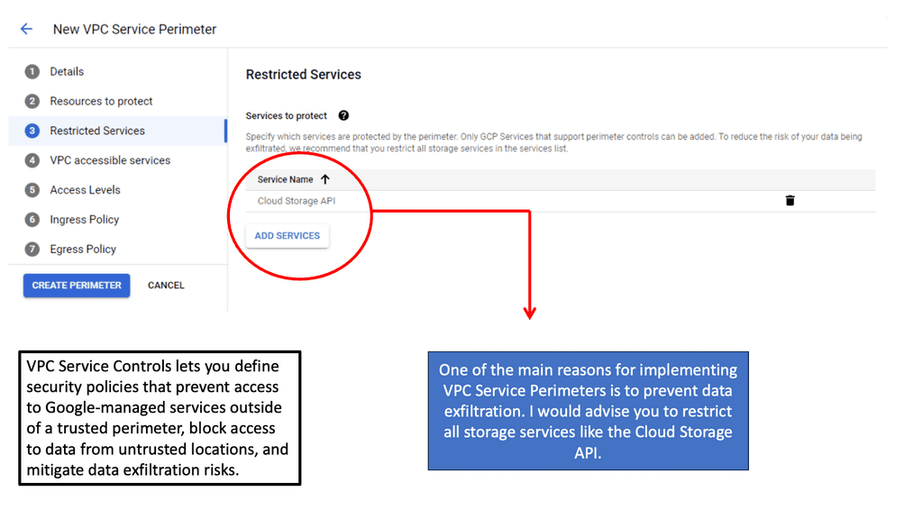
VPC Security Controls VPC Service Controls

Standard Data Center Design

**Traffic Flows**

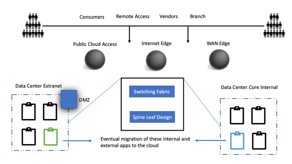
There will be the consumers of services. So, they can be customers, remote users, partners, and branch sites. These consumers will have to access applications which are hosted in the network or cloud domain. So, the consumers will typically have to connect to a WAN edge for applications hosted in the network.

On the other hand, if consumers want to connect to cloud-based applications, they can go directly to, let’s say, IaaS or the more common SaaS-based applications. Again, this is because access to cloud-based applications does not go via the WAN edge.

For consumers to access network applications not hosted in the cloud, as discussed, they are met with the WAN edge. Traffic will need to traverse the WAN edge to get to the application, which will have another layer of network and security functionality deeper in the network.

**WAN Edge Components**

At the network’s edge, we have many different types of network and security functionality. So, we will have standard routers, a WAN optimization controller, Firewalls, Email Gateways, Flow collectors, and other types of probes to collect traffic.

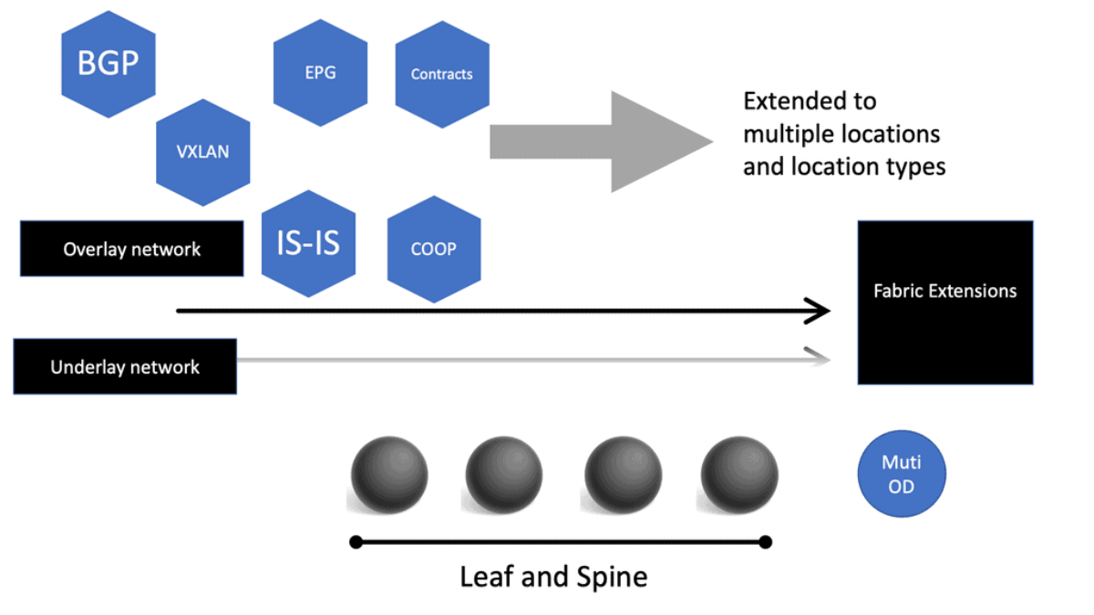
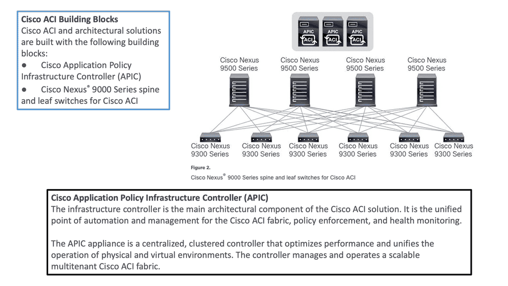
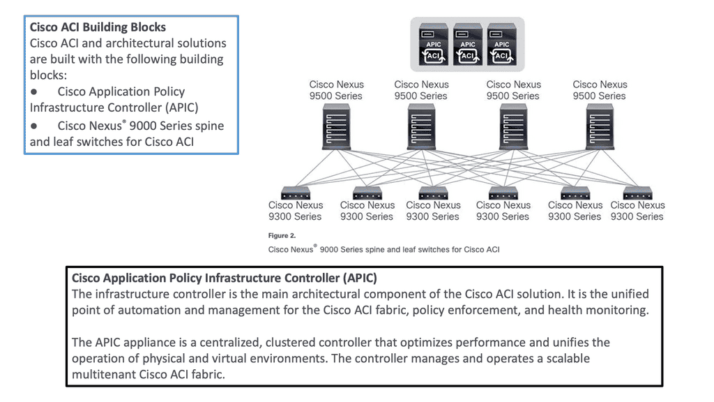
Then, a network will have to switch fabric. So, the old days of the 3-tier data Center architecture are gone. All primary switching fabrics or switching fabrics that you want IP forwarding to scale are based on the spine leaf architecture, for example, the Cisco ACI with ACI networks. The ACI Cisco has good Multi Pod and Multi-Site capabilities.

**Application Hosting**

Then, we go deeper into the applications and have app-tier access. So, we have application-hosted Internet for internal users. Each one will have its security, forwarding proxy devices, and load balancers. All these are physical wires tied to the fabric and will have limited capacity.

Example: MPLS Global WAN
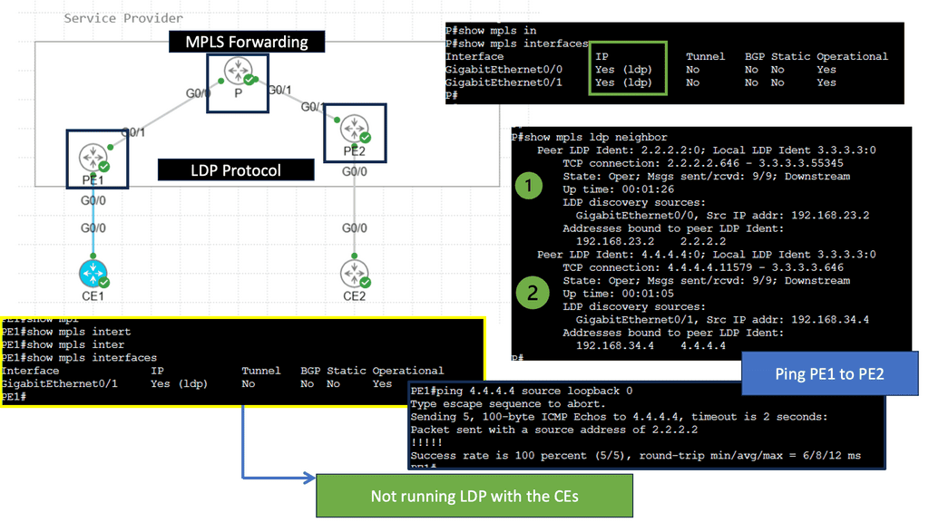
For global data center design. These will commonly connect over MPLS, which provides the Global WAN. Each data center would connect to an MPLS network and will usually be grouped by regions such as EMEA or AMERICAS. So, we have distributed networks, such as the MPLS network label switches. You can also have Segment Routing to provide this global WAN, which improves traffic engineering.

So, some common trends have challenged parts of this design. Many of these trends have called for the introduction of a new network area called the SASE fabric, commonly held in a CNF or a collocation facility. This fabric already has all the physical connectivity and circuits for you.

Common Trends: SASE Architecture

In a cloud-centric world, users and devices require access to services everywhere. These services are now commonly migrated to SaaS and IaaS-based clouds. So we have an app migration from “dedicated” private to “shared” public cloud. These applications became easy to change based on a microservices design. The growth was rapid, and now you must secure workloads in a multi-tenant environment.

SASE – **Identity is the new perimeter**

As a result, the focal point has changed considerably. Now, it is the identity of the user and device, along with other entities around the connection group, as opposed to the traditional model focusing solely on the data center. Identity then becomes the new perimeter. 

SASE – **Bandwidth Requirements**

Another major trend is that capacity requirements and bandwidth for public clouds doubled. Now that applications are hosted in the cloud, we also need to make changes on the fly to match the agility of the cloud.

When migrating these applications, we must rapidly upgrade internet-facing firewalling, for example, due to remote user access demands. Also, security teams demand IPS/AMP appliance insertions. In a cloud environment, it’s up to you to secure your workloads, and you need the same security levels in the cloud as you would on-premises.

SASE – **Constant Security Policy**

These apps are not in our data center, so we need to ensure that these migrated applications have the same security policy that would be housed in the AWS or Azure clouds. So we need more services in the current infrastructure.

Now we have more wiring and configuration, what is the impact on an extensive global network? You have a distributed application in several areas and want to open a port. These configurations need to be done and monitored in many places and with many teams.

Internal data applications are becoming less important than those that run in public clouds. More apps are in the cloud, and the data center is becoming less important as the prime focal point. The data center will always be retained, but the connectivity and design will change with the introduction of an SASE solution.

Security Solution Appliances

A. Different Technology Stacks:

Many common problems challenge the new landscape. Due to deployed appliances for different technology stacks for networking and security, not to mention the failover requirements between them, we are embedded with high complexity and overhead.

B. DMZ & Increased Latency:

The legacy network and security located in the DMZ designs increase latency. The latency is even with service chaining, but it will expand and become more challenging to troubleshoot. In addition, the world is encrypted. This needs to be inspected without degrading application performance.

C. Required: Global SASE Fabric

These challenges are compelling reasons to leverage a cloud-delivered SASE solution. The SASE architecture is a global fabric consisting of a tailored network for application types typically located in the cloud: SASE optimizes where it makes the most sense for the user, device, and application – at geographically dispersed PoPs. Many will connect directly to a colocation facility that can hold the SASE architecture.

D. Architectural Changes

The significant architecture changes you have seen in the past are that consumers, remote users, customers, branches, and partners will connect to the WAN edge, Internet, or IaaS via a colocation facility. Circuits migrated to selected “central hubs” connectivity and colocation sites from the data center.

The old DC will become another application provider connecting to the colocation. Before addressing what this collocation looks like, we will address the benefits of redefining the network and security architecture. Yes, adopting SASE reduces complexity and overhead, improves security, and increases application performance, but what does that mean practically?

Problems with complexity/overhead/processing/hardware-based solutions

E. Hardware Capacity Limits

Traditional mechanisms are limited by the hardware capacity of the physical appliances at the customer’s site and the lag created for hardware refresh rates needed to add new functionality. Hardware-based network and security solutions build the differentiator of the offering into the hardware. With different hardware, you can accelerate the services and add new features.

F. Feature Limits

Some features are available on specific hardware, not the hardware you already have on-site. In this case, the customer will need to do the heavy lifting. In addition, as the environment evolves, we should not depend on the new network and security features from the new appliance generation. This inefficient and complex model creates high operational overhead and management complexity.

G. Device Upgrades

Device upgrades for new features require significant management. From experience, changing out a line card would involve multiple teams. For example, if the line card ran out of ports or you need additional features from a new generation, 

This would involve project planning, on-site engineers, design guides, and, hopefully, line card testing and out-of-hours work. For critical sites to ensure a successful refresh, team members may need to be backed up. Many touches need to be managed.

SASE architecture overcomes tight coupling/hardware-based solutions.

Cloud-based SASE

The cloud-based SASE enables updates for new features and functionality without requiring new deployments of physical appliances. A physical appliance will still need to be deployed, but it can host many virtual networks and security functions, which has an immediate effect on ease of management.

Network and security deployment can now occur without ever touching the enterprise network, allowing enterprises to adopt new capabilities quickly. Once the tight coupling between the features and the customer appliance is removed, we have increased agility and simplicity for deploying network and security services.

Cisco SASE: Virtualization of Network Functions

With a Cisco SASE platform, when we create an object, such as the virtualization of Network Functions. The policy in the networking domain is then available in other domains, such as security. Network function virtualization, where we de-couple software from hardware, is familiar.

This is often linked to automation and orchestration, where we focus on simplifying architecture, particularly on Layer 4 – Layer 7 services. Virtual machine hosting has enabled the evolution of a variety of virtualized workloads. The virtualization of network and security functions allows you to scale up, down, and in and out at speed and scale without embedding service.

Example: Virtual Appliances

Let’s say you have an ASAv5 as a virtual appliance. This virtual appliance has, for example, 1 Core. If you want more cores, you can scale up to support ASA v50, which supports eight cores. So we can scale up and down. However, what if you want to scale out?

Multipath load balancing

Here, we can add more cloud service providers and ASAv to scale out virtual firewalls with equal-cost multipath load balancing. You want to buy something other than a physical appliance that will only ever do one function. The days of multiple physical point solutions are ending as sase gains momentum. Instead, you want your data center to scale when capacity demands it without physical limitations.

Cisco SASE Architecture: NFV

NFV network services can be deployed and managed much more flexibly because they can be implemented in a virtualized environment using x86 computing resources instead of purpose-built dedicated hardware appliances. The CSP 5000 Series can help you make this technology transition.

In addition, with NFV, the Cisco SASE open approach allows other vendors to submit their Virtual Network Functions (VNF) for certifications to help ensure compatibility with Cisco NFV platforms.

Cloud Services Platform

This central location is a PoP that could be a Cloud Services Platform that could provide the virtualized host. For example, the Cloud Services Platform CSP-5000 could host CSR, FTD, F5, AVI networks, ASAv, or KVM-based services. These network and security functions represent the virtual network appliances that consist of virtual machines. 

  • Cisco SASE and the CSP 5000

Within the Cisco SASE design, the CSP 5000 Series can be deployed within data centers, regional hubs, colocation centers, the WAN edge, the DMZ, and even at a service provider’sprovider’s Point of Presence (PoP), hosting various Cisco and third-party VNFs. We want to install the CSP at a PoP, specifically in a collocation facility. If you examine the CSP-5000 for a block diagram, you will see that Cisco SASE has taken a very open ecosystem approach to NFV, such as Open vSwitch. 

  • Key Technology: SR-IOV

It uses Single Root I/O Virtualization (SR-IOV) and an Open vSwitch Data Plane Development Kit (OVS-DPDK). The optimized data plane provides near-line rates for SR-IOV-enabled VNFs and high throughput with OVS DPDK interfaces.

  • The Role of the OVS

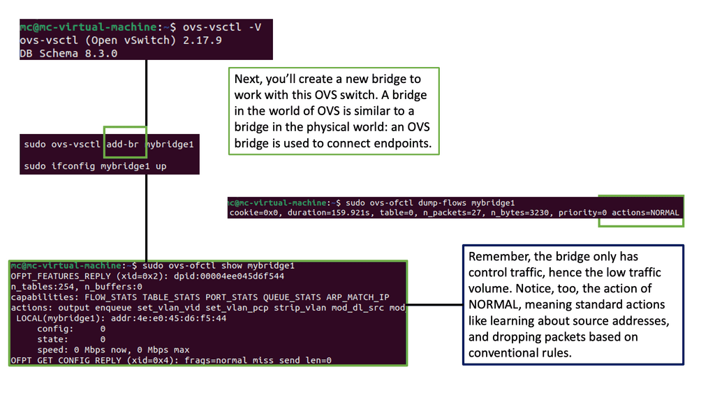
The CSP has a few networking options. First, the Open vSwirch ( OVS) is the Software layer two switches for the CSP-500. So, the CSP internal software switches bridge the virtual firewall to the load balancer to the ToR switches. You can also use SR-IOV Virtual Ethernet Bridge Mode (VB), which performs better. As a third option, we have SR-IOV, virtual Ethernet Port Aggregators Mode (VEPA)
**Cisco SASE Security Policies** 

With the flexible design Cisco SASE offers, any policies assigned to users are tied to that user regardless of network location. This removes the complexity of managing network and security policies across multiple locations, users, and devices. But, again, all of this can be done from one platform.

SASE  architecture overcomes the complexity and heavy lifting/scale.

**A Personal Note: SASE** 

I remember from a previous consultancy. We were planning next year’s security budget. The network was packed with numerous security solutions. All these point solutions are expensive, and there is never a fixed price, so how do you plan for this? Some new solutions we were considering charge on usage models, which we needed the quantity at that time. So the costs keep adding up and up.

SASE removes these types of headaches. In addition, consolidating services into a single provider will reduce the number of vendors and agents/clients on the end-user device. So we can still have different vendors operating a sase fabric, but they are now VNF on a single appliance.

**Complexity Reduction**

Overall, substantial complexity savings will be from consolidating vendors and technology stacks, pushing this to the cloud away from the on-premises enterprise network. The SASE fabric abstracts the complexity and reduces costs. In addition, from a hardware point of view, the cloud-based SASE can add more PoPs of the same instance for scale and additional capacity. This is known as vertical scaling, and also, in new locations, known as horizontal scaling.

**SASE Overcomes Intensive Processing**

Additionally, the SASE-based cloud takes care of intensive processing. For example, as much of internet traffic is now encrypted, malware can use encryption to evade and hide from detection. Here, each PoP can perform deep packet dynamics on TLS-encrypted traffic.

**Encryption/Decryption**

You may not need to decrypt to fully understand the payload. Still, partial decryption and examining payload patterns to understand the malicious activity seem enough. The SASE vendor needs to have some Deep Packet Dynamic technologies.

**Challenge: Traditional Firewalling**

Traditional firewalls are not capable of inspecting encrypted traffic. Therefore, performing DPI on TLS-encrypted traffic would require extra modules or a new appliance. A SASE solution ensures the decryption and inspection are done at the PoP, so no performance hits or new devices are needed on the customer sites. This can be done with Deep Packet Dynamic technologies.

Performance Problems – Packet drops/latency

Network congestion resulting in dropped and out-of-order packets could be better for applications. Latency-sensitivity applications such as collaboration, video, VoIP, and web conferencing are hit hardest by packet drops. Luckily, there are options to minimize latency and the effects of packet loss.

1. **WAN Optimization**

SD-WAN solutions have WAN optimization features that can be applied on an application-by-application or site-by-site basis. Along with WAN optimization features, there are protocol and application acceleration techniques.

2.**Privatize the WAN**

In addition to existing techniques to reduce packet loss and latency, we can privatize the WAN as much as possible. To control the adverse and varying effects the last mile and middle mile have on applications, we can privatize with a private global backbone consisting of a fabric of PoPs.

Once privatized, we have more control over traffic paths, packet loss, and latency. A private network fabric is a crucial benefit of SASE, as it drives application performance. So we can inspect east-west and north-south traffic.

3.** Traffic Engineering**

Traffic engineering and performance improvement are easy since we have a centralized fabric consisting of many hubs and spokes. When you centralize some of the architecture into a centralized fabric, it is easier to make traffic adjustments globally. The central hub will probably be a collocation facility and can be only one hop away, so the architecture will be simpler and easier to implement.

PoP optimization – Routing algorithms, and TCP proxy.

Each PoP in the SASE cloud-based solution optimizes where it makes the most sense, not just at the WAN edge. For example, within the SASE fabric, we have global route optimizations to determine which path is best and can be changed for all traffic or specific applications.

4.**PoP acting as TCP Proxy**

These routing algorithms factor in performance metrics such as latency, packet loss, and jitter. I am selecting the optimal route for every network packet. Unlike internet routing, which favors cost over performance, the WAN backbone constantly analyzes and tries to improve performance.

Example: Increasing The TCP Window Size

-As everything is privatized, we have all the information to create the largest packet size and use rate-based algorithms over traditional loss-based algorithms. As a result, you don’t need to learn anything, and throughput can be maintained end-to-end.

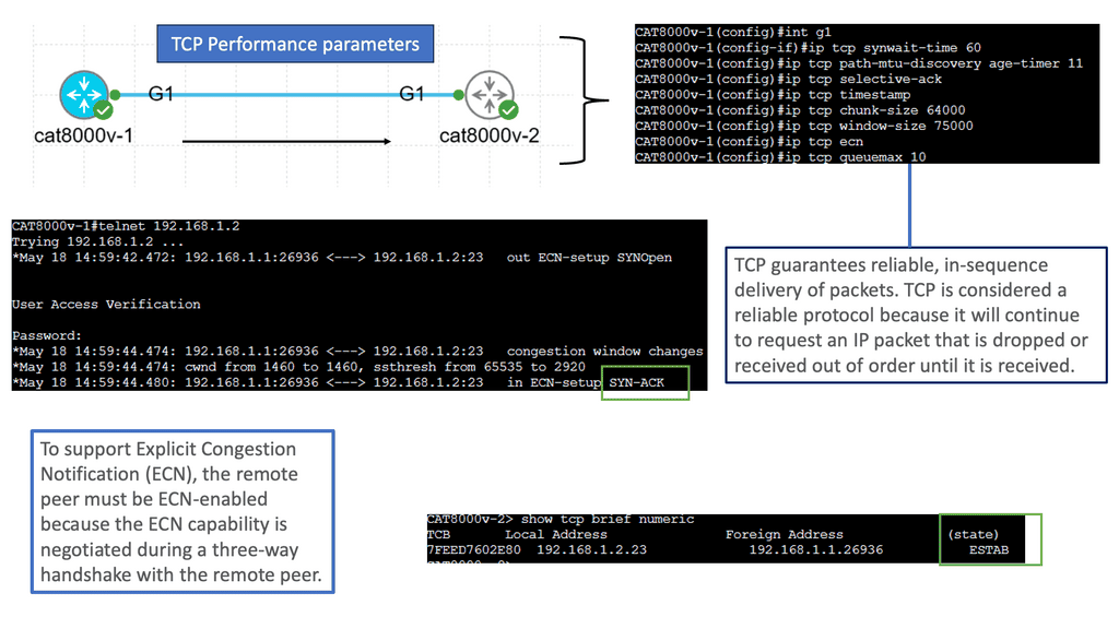
– As each PoP acts as a TCP proxy server, techniques are employed so that the TCP client and server think they are closer. Therefore, a larger TCP window is set, allowing more data to be passed before waiting for an acknowledgment.

Example Technology: TCP Performance Parameters
Summary: SASE Solution

In today’s rapidly evolving technological landscape, traditional networking approaches are struggling to keep up with the demands of modern connectivity. Enter SASE (Secure Access Service Edge) – a revolutionary solution that combines network and security capabilities into a unified cloud-based architecture. In this blog post, we explored the key features and benefits of SASE and delve into how it is shaping the future of networking.

Understanding SASE

SASE, pronounced “sassy,” represents a paradigm shift in networking. It converges wide-area networking (WAN) and network security services into a single, cloud-native solution. By integrating these traditionally disparate functions, organizations can simplify network management, improve security, and enhance overall performance. SASE embodies the principles of simplicity, scalability, and flexibility, all while delivering a superior user experience.

The Power of Cloud-native Architecture

At the core of SASE lies its cloud-native architecture. By leveraging the scalability and agility of the cloud, organizations can dynamically scale their network and security resources based on demand. This elasticity eliminates the need for costly infrastructure investments and allows businesses to adapt quickly to changing network requirements. With SASE, organizations can embrace the benefits of a cloud-first approach without compromising on security or performance.

Enhanced Security and Zero Trust

One of the key advantages of SASE is its inherent security capabilities. SASE leverages a Zero Trust model, which means that every user and device is treated as potentially untrusted, regardless of their location or network connection. By enforcing granular access controls, strong authentication mechanisms, and comprehensive threat detection, SASE ensures that only authorized users can access critical resources. This approach significantly reduces the attack surface, mitigates data breaches, and enhances overall security posture.

Simplified Network Management

Traditional networking architectures often involve complex configurations and multiple point solutions, leading to a fragmented and challenging management experience. SASE streamlines network management by centralizing control and policy enforcement through a unified console. This centralized approach simplifies troubleshooting, reduces administrative overhead, and enables organizations to maintain a consistent network experience across their distributed environments.

Conclusion

As the digital landscape continues to evolve, embracing innovative networking solutions like SASE becomes imperative for organizations seeking to stay ahead of the curve. By consolidating network and security functions into a unified cloud-native architecture, SASE provides simplicity, scalability, and enhanced security. As businesses continue to adopt cloud-based applications and remote work becomes the norm, SASE is poised to revolutionize the way we connect, collaborate, and secure our networks.

rsz_1secure_automation333

Security Automation

Security Automation

In today's fast-paced digital landscape, ensuring the security of our online presence has become more critical than ever. With the ever-evolving threat landscape and increasing complexity of cyberattacks, manual security measures may no longer suffice. This is where security automation comes into play, revolutionizing the way we protect our digital assets. In this blog post, we will explore the benefits of security automation and how it can effectively safeguard our digital world.

Security automation is the process of automating security tasks and processes to enhance the efficiency and effectiveness of security operations. It involves leveraging technologies such as artificial intelligence, machine learning, and robotic process automation to streamline security processes, detect threats in real-time, and respond promptly to mitigate risks. By automating repetitive and time-consuming tasks, security teams can focus on more strategic activities.

Enhanced Threat Detection and Response: With security automation, organizations can detect and respond to threats in real-time, significantly reducing the time it takes to identify and mitigate security incidents. Automated systems can analyze vast amounts of data, identify patterns, and generate alerts for potential threats, enabling security teams to respond swiftly and effectively.

Improved Efficiency and Productivity: By automating routine security tasks, organizations can free up valuable resources and allocate them to more critical security activities. This leads to increased efficiency and productivity within the security operations, allowing teams to better prioritize and manage security incidents.

Consistency and Accuracy: Manual security processes are prone to human error, which can have severe consequences in the realm of cybersecurity. Security automation ensures consistent execution of security measures, eliminating the possibility of human oversight or negligence. Automated systems follow predefined rules and guidelines, ensuring accuracy and reducing the risk of human-induced vulnerabilities.

Threat Intelligence and Analysis: Automated threat intelligence platforms can continuously monitor and analyze vast amounts of data from multiple sources, including threat feeds, vulnerability databases, and security event logs. By aggregating and correlating this information, organizations can gain valuable insights into emerging threats and proactively implement mitigation measures.

Incident Response and Remediation: Security automation facilitates rapid incident response by automating the process of gathering evidence, containing threats, and initiating remediation actions. Automated incident response workflows can be triggered based on predefined rules and playbooks, ensuring consistent and timely response to security incidents.

In an increasingly interconnected and digital world, security automation offers a powerful solution to safeguard our digital assets. By leveraging automation technologies, organizations can enhance threat detection and response capabilities, improve efficiency and accuracy, and proactively protect against emerging threats. Embracing security automation is not merely an option but a necessity in today's evolving threat landscape. Let us harness the power of automation to fortify our digital world and ensure a secure future.

Highlights: Security Automation

Automation Scenarios

We can apply our knowledge of automation to different scenarios and workloads that revolve around security. For example, when tedious and everyday tasks are automated, individuals doing those tasks can focus on solving the security problems they are dealing with. This enables a whole new way of looking at how we learn about security, how much we can store, process, and analyze log data (DFIR), and how we can keep applying security updates without interruptions (security operations).

At its core, security automation involves using advanced technologies and intelligent systems to automate various security processes. It enables organizations to streamline security operations, detect real-time threats, and respond swiftly and effectively. From threat intelligence gathering to incident response and recovery, automation is pivotal in strengthening an organization’s security posture.

Key Benefits of Security Automation:

a) Enhanced Threat Detection: By deploying intelligent monitoring systems, security automation can swiftly identify and respond to potential threats in real-time. This proactive approach minimizes the risk of breaches and allows security teams to stay one step ahead of malicious actors.

b) Accelerated Incident Response: Manual incident response can be time-consuming and prone to delays. However, with security automation, incidents can be detected, analyzed, and remediated swiftly and accurately. Automated incident response workflows can help contain and mitigate security breaches before they escalate, reducing the organization’s impact.

c) Efficient Vulnerability Management: Identifying and patching vulnerabilities is critical to maintaining a secure infrastructure. Security automation tools can continuously scan networks, applications, and systems, providing organizations with real-time vulnerability assessments. This enables security teams to prioritize and address vulnerabilities promptly, reducing the window of opportunity for potential attackers.

Integrated Automation Platform

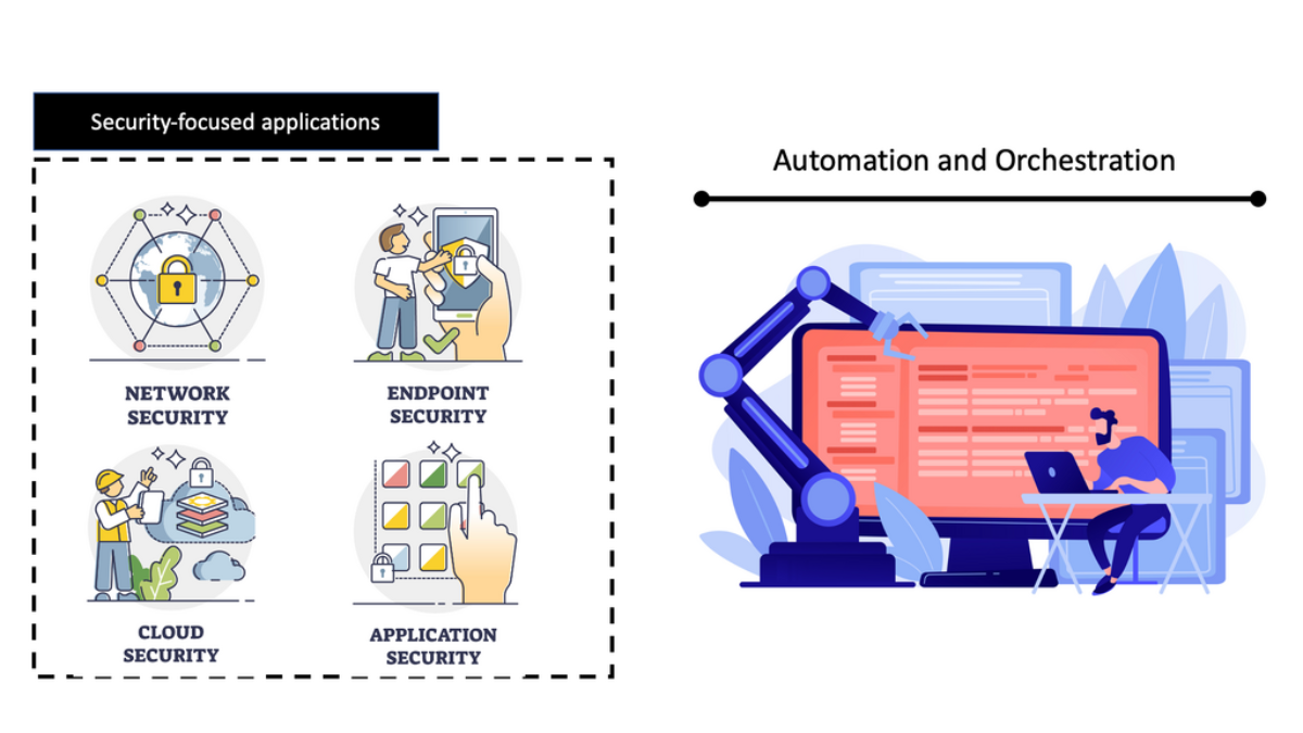
If you are only using scripting in the security automation world, it will only get you so far. Eventually, you will need a fully integrated platform with your security and network infrastructure. For secure automation, there are different types of platforms you can use. This post will address two different types.

Example: Red Hat Tower can integrate and configure network and security devices—also, Splunk SOAR. The SOAR meaning is about abstracting complexity away with security-focused playbooks. This reduces repetitive work and the ability to respond to security events in a standardized way.

**Platform Examples**

Backing up configs and collecting logs is only a tiny part of automation. Red Hat Ansible Tower and Splunk SOAR have new ways to reach the most advanced use cases. For security automation, Splunk Security with Splunk SOAR has a security-focused application consisting of specially crafted playbooks for every security requirement.

**Red Hat Ansible Tower**

For example, you can check the domain and file reputation or create your own. On the other hand, Red Hat Tower Ansible Architecture allows you to securely reach and support the most edge use cases with increased portability using execution environments and automation mesh. In addition, you can securely bring automation to the edge with a certain overlay functionality.

**Splunk SOAR**

The difference between an attack being a routine annoyance and a catastrophic event comes down to a product’s robustness and the technologies you choose to adopt. Splunk has several products that can help you here, ranging from the Splunk SIEM to the Splunk SOAR. There are also several Observability products, all of which are well-integrated and can assist you with security automation. 

Example: Splunk Enterprise & Cloud

Customers can solve their primary SIEM use cases using Splunk Enterprise and Cloud, core Splunk platforms that provide collection, indexing, search, and reporting capabilities. The Splunk SIEM collects or ingests machine data and can make this available to the Splunk SOAR.

Automation with Security Command Center (SCC)

**Understanding the Core Features of Security Command Center**

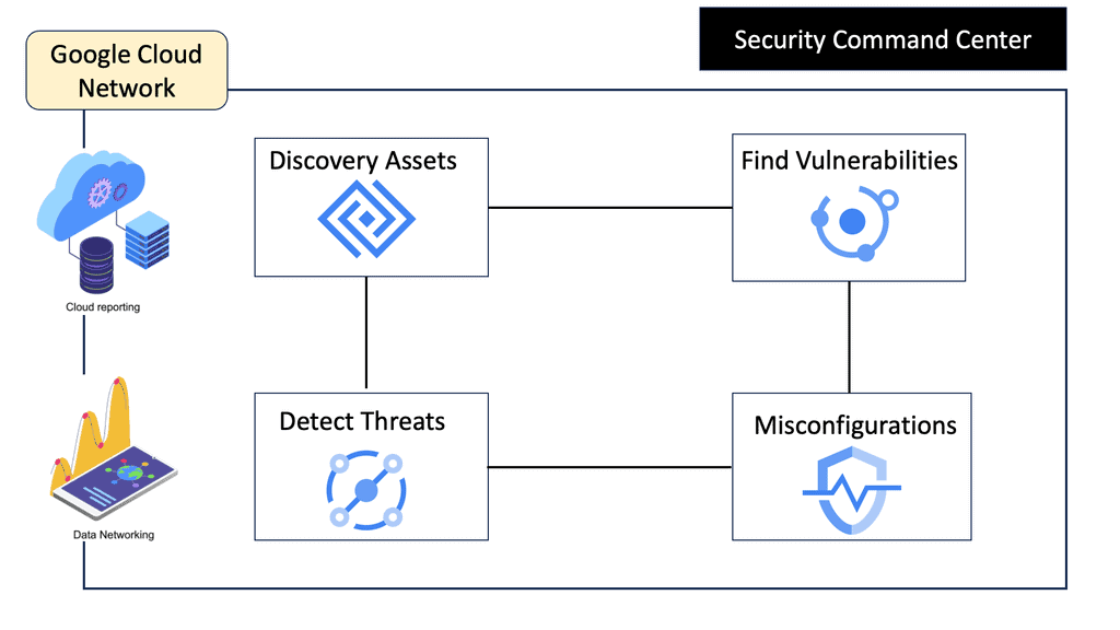
Security Command Center stands out with its robust set of features tailored for Google Cloud environments. At its core, SCC offers asset inventory management, enabling security teams to gain a clear view of their cloud assets and configurations. The integration with other Google Cloud security tools enhances its capabilities, providing automated threat detection that identifies vulnerabilities, misconfigurations, and potential security threats across your cloud infrastructure. Moreover, the centralized dashboard of SCC allows for real-time monitoring and quick response to incidents, ensuring that your organization’s digital assets remain secure.

**Automating Threat Detection with Google Cloud Security**

One of the standout benefits of Security Command Center is its automation capabilities. By leveraging machine learning and advanced analytics, SCC automates the process of threat detection, significantly reducing the time and effort required by security teams. This automation not only minimizes the chances of human error but also ensures that threats are identified and addressed promptly. With built-in integration to Google Cloud’s security products like Cloud Armor and VPC Service Controls, SCC provides a seamless and holistic approach to safeguarding your cloud environment.

**Investigating Threats: A Step-by-Step Approach**

Once a threat is detected, the investigation phase is crucial to understanding and mitigating the risk. Security Command Center simplifies this process with its detailed logging and alerting system. Security teams can follow a structured approach to investigate threats, starting with analyzing alerts, examining the affected resources, and understanding the potential impact. SCC’s comprehensive logging capabilities provide valuable insights into the nature of threats, helping teams to develop effective response strategies and prevent future occurrences.

**Enhancing Your Security Posture with SCC**

Beyond threat detection and investigation, Security Command Center offers tools to enhance your organization’s overall security posture. By providing insights into security best practices and compliance requirements, SCC helps organizations align their security strategies with industry standards. The tool’s continuous monitoring capabilities ensure that your security measures are always up-to-date, adapting to the ever-changing threat landscape.

Security Automation: The World of Scripting

Challenge: Self-driving Scripts 

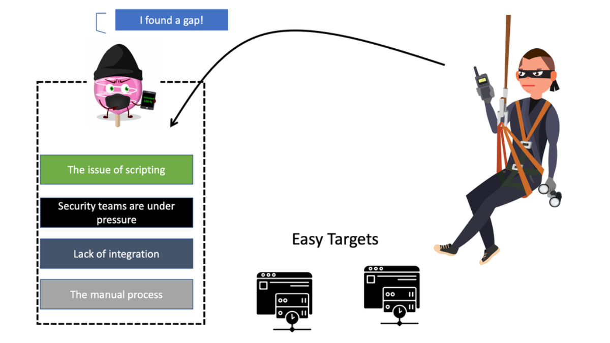
In the traditional world of security automation, it was common to use custom in-house automation frequently. As a result, we have a variety of self-driving scripting methods that solve specific short-term security problems. For example, for secure automation, you may need to collect logs from several devices for security. However, this is far from a scalable and sustainable long-term approach to an enterprise’s automation strategy.

With more self-maintained scripting tools and working in siloed, you are creating more security blind spots. With more point tools, you have to make more silos and potential security blind spots, which may trigger the adoption of more narrowly focused tools. The more tools you have, the less control over your environment that could easily open up the spread of lateral movements.

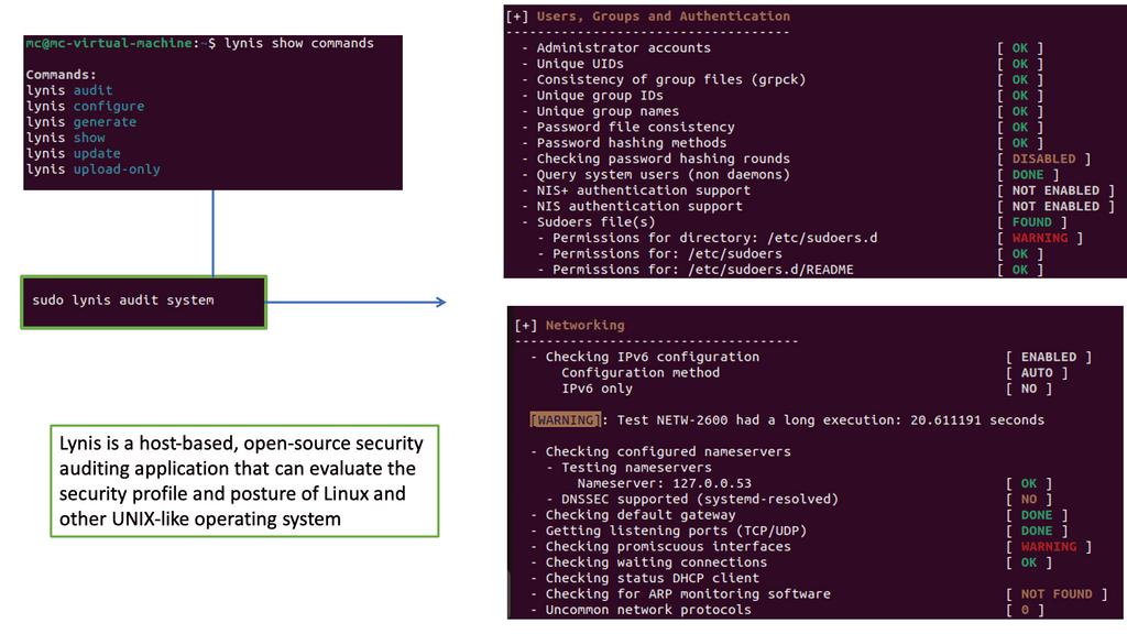
Example: Security Scan with Lynis

Lynis offers a wide range of features that contribute to its effectiveness as a security scanning tool. It utilizes a modular and extensible framework, allowing easy customization and integration with other security tools. With its powerful scripting abilities, Lynis can automate security audits and generate detailed reports. It also supports local and remote scanning, making it suitable for various environments.

Required: The need for a security platform

For example, look at lateral movements in an Active Directory (AD) network. Lateral movements are a real problem, and some advances in lateral movement techniques have been made using Metasploit, Impact, and PurpleSharp. However, detecting whether this is a bad actor or a sys admin carrying out daily activities can be challenging.

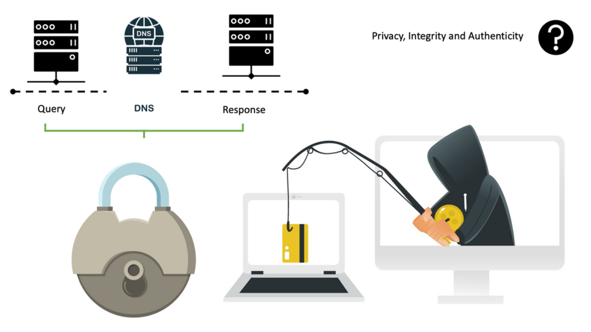
Once the bad actor stealthily navigates the network with lateral movements, they can compromise accounts, find valuable assets, and gradually exfiltrate data. All of this can be unnoticed with a below-the-radar style of attacks. A favored vector is to use DNS to exfiltrate data. Therefore, DNS often needs to be checked.

Related: For additional pre-information, you may find the following post helpful:

  1. Cloud Native meaning
  2. SASE Definition

Security Automation

SOAR meaning: A quick point

In this case, you should integrate Splunk SOAR with User Behaviour Analytics (UBA) to detect deviations from the baseline. UBA works with unsupervised machine learning and builds profiles of entities on the network. Today’s attacks are distributed, and multiple entities are used to stage an attack.

An anomaly is sent once there is a significant deviation from normal entity behavior. Of course, an anomaly does not necessarily mean a threat. However, the anomaly can be combined with other network and infrastructure aspects to determine if a bad actor exists. So, for example, we would look at the time of day, frequency, or any other usual activity, such as privilege escalation techniques.

  • Lack of Speed

Without integrated security tools with security automation and a lack of automated and orchestration processes. The manual response slows MTTR and increases the possibility of a successful threat. Bad actors can breach and exfiltrate data when the mean time to detect (MTTD) is too long.

So, the manual approach to detecting, triaging, and responding to threats must be faster. For example, ransomware is quick; the game is over once the binaries are executed. It would help if you focused your efforts on the detection phase of the kill chain and caught any lateral movements, even when they pivot to valuable assets.

  • The Need for Security Automation

To address this challenge, you need a security solution that integrates its existing security products to reduce the response and remediation gap. In addition, these automation and orchestration events must be carried out across all its security vendors to consolidate response and remediation.

For secure automation, a unified and standard response to security can be made using pre-approved policies, consistently configuring resources according to pre-approved guidelines, and proactively maintaining them in a repeatable fashion.

Level of Automation Maturity

  • Security-focused content collection

This provides a faster, more efficient, and streamlined way to automate the identification, triage, and response processes to security events. In addition, we can use security-focused content. In the case of Red Hat Tower, this comes in the form of collections of roles and modules dedicated to security teams.

Splunk SOAR also has secure-focused applications and content ready to use in the Splunk database. The pre-approved policies and playbooks of Ansible Tower and Splunk SOAR will reduce the chances of misconfiguration and speed up all aspects of security investigation.

  • Secure Automation and Orchestration

When a few waves of Malware, Phishing, Ransomware, and under-the-radar attacks target you, automation and orchestration are the only ways to combat this. Security automation does most of the work, so you no longer have to weed through and manually address every alert as it comes in or process every security action or task.

For example, the level of automation you want to adopt depends on the maturity level of the automation you already have in our environments. If you are new to automation, you can have SOAR or Tower playbooks send an alert for further investigation. So, you can start with a semi-automated approach.

However, if you are further in your automation strategy, you can combine different playbooks to carry out coherent security detection and response. It’s easy to do this in SOAR with a playbook visualizer, and Ansible Tower has workflow templates that can be used with role-based access control.

**Red Hat Tower: How to Start**

In most organizations, we have IT operations and a security team. These teams have traditionally disjoint roles and responsibilities. The IT Operations are hardening systems, managing the infrastructure, and deploying and maintaining systems. The security operations team would track ongoing threats, perform intrusion detection/prevention, and perform firewall management activities.

A. Ansible has a common language.

With these two disjointed teams, we can use Ansible as the common automation language for everyone across your organization. Specifically, Red Hat Tower can be the common language between security tools and can be used for various security use cases that can bring the two teams together.

B. Red Hat Tower: Security Automation

Red Hat Tower can orchestrate security systems using a series of curated security collections of modules, roles, and playbooks to investigate and respond to threats using trusted content. This enables you to coordinate your enterprise security systems to perform several security duties, such as investigation enrichment, threat hunting, and incident response.

C. Pre-approved Playbooks

You can integrate Red Hat Tower with your security infrastructure here and have pre-approved playbooks ready to run upon threat detection. For example, a playbook can be automatically triggered by the results of a security scan. The following lists some of the use cases for Ansible Tower playbooks.

Security Automation Examples

1) Secure Automation: Security Patching

You could start with patching. Not patching your servers is one of the biggest causes of breaches. Automated patching boosts system security and stability, improving uptime. And this will be noticed straight away.

2) Secure Automation: System Hardening

Then, activities such as system hardening are something everyone can do for all systems. With automation, we can rapidly identify systems that require patches or reconfiguration. Then, applying patches or changing system settings consistently across many systems is easier according to defined baselines. For example, make changes to your SSH config.

Here, you can use automation to configure the SSH daemon and not allow authentication using an empty password. You can run these playbooks in check mode so those who don’t require full automation rights can run checks safely. Again, I would combine this with role-based access control.

3) Secure Automation: Network Configuration 

For network management, you can configure an ACL or filter to restrict ACL or filter management access to the device from only the management network. You can also use automation to lock down who has managed to access specific subnets.

4) Secure Automation: Firewall Integration

If an increase in incident management tickets is due to incorrect firewall rules causing an increase in change requests, aim to reduce the number of tickets or change requests through automation. For our Firewall integration, the role of automation can speed up policy and log configuration changes.

For example, we can add an allowlist entry in the firewall configuration to allow traffic from a particular machine to another.

We can automate a playbook that adds the source and destination IPs as variables. Then, when a source and destination object are defined, the actual access rule between those is defined.

5) Secure Automation: Intrusion Detection and Prevention Systems

Tower can simplify the rule and log management for your intrusion detection and prevention systems. Automation can be used to manage IDPS rules, and IDPS roles are offered. These roles can work with multiple IDPS providers, so the corresponding playbook needs to have a variable stating the actual IDPS provider. 

Once the role is imported, and this is the first step, the new IDPS rule is handed over via defined variables:

6) Secure Automation: Privileged Access Management (PAM) Tools

Ansible Tower can streamline the rotation and management of privileged credentials to automate the prevention. So we can streamline credential management, which is hard to do manually. 

7) Secure Automation: Endpoint Protection

Automation can simplify everyday endpoint management tasks, integrate into Endpoint Protection, and provide event-driven detection, quarantining, and remediation. 

Advanced Red Hat Tower Features

Job Templates vs. Workflow Template

When creating a job template, we choose a job or workflow template. We choose the job template to develop simple employment out of it. However, creating more complex jobs composed of multiple job templates, with flow control features between one position and the next, is possible with a workflow template. This workflow template can also be integrated into your CI/CD pipelines and Jenkins.

Security Benefits

This makes it easier to have playbooks that are job templates from different teams. This is used in large environments, so multiple job templates are connected. Then, complex interactions between jobs can be defined in a workflow before the next job starts, depending on the previous position. Any inventory and any credentials can be used. So, it brings a lot of flexibility to automation.

In its multi-playbook workflows, the user can create pipelines of playbooks to be executed in sequence on any inventory using one or more users’ credentials. Security teams can configure a series of jobs that share inventory, playbooks, or permissions to fully automate investigations or remediations, bringing many consistency and security benefits.

Ansible Tower and Scheduling:

With Ansible Tower, we have Templates with the Launch feature; think of this as an ad hoc way to run Ansible for one of the tasks. However, if you are using Tower, you should use Schedules to control your automation better. For example, you may have a maintenance window when you apply changes. Here, we can set the times and frequency of playbook runs.

Scheduling this playbook in Tower will automatically refresh systems significantly out of spec. This includes calling back into Tower to apply our basic configuration once new instances are spun up with the provisioning callback feature. I find this useful for dynamic cloud environments.

GitHub for Playbooks

GitHub is all about version control, so multiple people can work on different types of code and review and merge changes. It’s also about managing change in your other environments. When Red Hat Tower runs the playbooks, it checks the URL specified in your playbooks, and here, we can have multiple options that can enhance your GitHub integrations, such as webhooks and personal access tokens.

Benefits: Removes Inconsistency of Playbooks

This is an important feature to enable as if you don’t have it checked; there is the possibility that someone notices a problem in a playbook and fixes it, then they run the playbook feeling sure that they are running the latest version.

Someone must remember to run the synchronization task before running the playbook, effectively running the older version.

Therefore, when using this option, we are removing the inconsistency of playbooks. So, increasing your security posture is very important. A lot of security breaches first start with a simple misconfiguration.

SOAR for Automation: SOAR Meaning

  • Splunk SOAR Meaning

Splunk SOAR drives accuracy and consistency in the incident response process. With SOAR, workflows can be orchestrated via integrations with other technologies and automated to achieve desired outcomes. Utilizing automation with Splunk SOAR can dramatically reduce the time to investigate malware alerts, driving accuracy and consistency across its incident response processes.

  • SOAR and Phantom

SOAR is the rebranding of Phantom but has multi-deployment options. Phantom was just on-premise, but now we have both on-premise and on-cloud delivery.  Consider SOAR as a layer of connective tissue for all security operations.

Decision-making and action need to be automated. SOAR can turn proceeds into playbooks, allowing us to create complex security operation workflows.

We have an extensive collection of security-focused SOAR applications that interact with the API of existing security and network infrastructure, such as your Firewalls, to support activities such as containment and recovery. We’ll talk about these in a moment.

  • Automation Broker

We have an Automation Broker, a modified version of Splunk SOAR with reduced features. It’s a reverse proxy for automation actions. The Automation Broker is a Docker container that uses an encrypted outbound connection from Splunk Cloud SOAR to the customer premises. As the communication is set outbound on the firewalls, it would help to open inbound ports to the perimeter firewall.

Security-Focused Playbooks

**SOAR Meaning: Security-Focused Playbooks**

Instead of manually going into other security tools and injecting data, enriching logs, and carrying out actions such as blocking or manual analysis intervention, SOAR playbooks can be used. You can have several security-focused playbooks that automatically carry out the tasks. The SOAR playbook can automate many repetitive duties. For example, you no longer have to respond manually to repetitive incidents. For example, you can have Splunk SOAR respond to malicious emails with playbooks. 

**Actions based on the Playbooks**

Then, we could have a list of actions based on playbook results. This could include additional investigation tasks or notifying users. Finally, when you want to push the boundaries of automation, we could take several steps to isolate or quarantine hosts, depending on the results of the previous playbooks. These steps would be integrated with multi-factor authentication to ensure the action is appropriately authorized. 

Splunkbase with Security-related Apps

Additionally, Splunkbase offers over 800 other security-related apps with pre-built searches, reports, and visualizations for specific third-party security vendors. These ready-to-use apps and add-ons help monitor security, a next-generation firewall, and advanced threat management capabilities. You can even build your custom application, from monitoring and Observability to improving safety.

**SOAR Meaning: SOAR Apps**

You are using many tools from many vendors, and when you respond, each one performs a different event and function. Splunk integrates with all devices with API, and SOAR can directly integrate all tools to act in a specific sequence.

So it can coordinate all security actions. With SOAR, you don’t get rid of your existing tools; instead, SOAR can sit between them and abstract a lot of complexity.

Think of Splunk as the conductor that supports over 350 apps. It has tools to build apps; you can create your own if it has an API. In addition, it can perform over 2000 actions. SOAR apps are Python modules that collect events from anything, such as SIEM, then normalize the information and make it available to playbooks.

**SOAR Meaning: Example: SOAR playbooks**

We have a network-based sandbox to detect malware that can enter via email. An Alert is received from SIEM, sent to SOAR, and triggers a playbook. SOAR communicates back to SIEM to query Active Directory to identify who is there and which department, and based on that, SOAR can query Carbon Black to see how the threat lives.

Finally, the SOAR can notify an analyst to manually intervene and double-check the results. This could take 30 mins by hand, but SOAR can do it in 30 seconds. 

Let’s look at another SOAR playbook in action. A Splunk SOAR playbook is triggered when an email malware alert is received. Due to the lack of context in these alerts, Splunk SOAR’s first order within the playbook is to query the security information and event management (SIEM) solution for all recipients, then Active Directory to collect context from all affected users’ profiles, business groups, titles, and locations.

A key point: SOAR means with workbooks and phases

Another name for a playbook is the SOAR workbook. Each workbook can have several phases, each with tasks to carry out our security actions. In this scenario, one phase and several playbooks will be in a single step. Some playbooks can be triggered automatically, and some are invoked manually.

Then, some are being gathered manually but will have prompts for additional information. These tasks will be semi-automatic because they can automatically import data for you and enrich events. Furthermore, they can import this data and enhance events from several platforms. 

Prevent Lateral Movements

A **Splunk and Lateral Movements**

You can have playbooks to hunt for lateral movements. There are many ways to move laterally in active directory networks. For example, Psexec is a sysadmin tool that allows admins to connect to other machines and perform admin tasks remotely. However, what if psexec is used to gain a remote shell or execute a PowerShell cradle on a remote device? When looking for lateral movement, we identify processes connecting remotely to a host.

B **Lateral Movement Activity**

To start a threat investigation, we could have a playbook to conduct an initial search for a known lateral movement activity. Windows security logs contain a wealth of information. The playbook can look for authentication events over the network from rare or unusual hosts or users.

C **Event Window Code**

For example, in a Windows event log, you would see a Windows event code for successful login, another log for a network connection, and another for privilege escalation events. Each event doesn’t mean much by itself but indicates a threat together. For example, here you can see that someone has used an admin account to connect over the network from a particular host and gained command-line access to a victim host.

D. Splunk SOAR’s visual playbook editor

Splunk SOAR comes with 100 pre-made playbooks, so you can start automating security tasks immediately and hunt for lateral movements. To simplify life, we have a Splunk SOAR visual playbook editor that makes creating, editing, implementing, and scaling automated playbooks easier to help your business eliminate security analyst grunt work.  

Popular Playbook Examples

  • Splunk Intelligence Management (TruSTAR) Indicator Enrichment

Then, we have a Splunk Intelligence Management (TruSTAR) Indicator Enrichment. This playbook uses Splunk Intelligence Management normalized indicator enrichment, which is captured within the notes of a container. An analyst can view details and specify subsequent actions directly within a single Splunk SOAR prompt for a manual response.

  • Crowdstrike Malware Triage

There is a Cowdstrike Malware Triage. This playbook walks through the steps performed automatically by Splunk SOAR to triage file hashes ingested from Crowdstrike and quarantine potentially infected devices.

  • Finding and Disabling Inactive Users on AWS Splunk SOAR’s

Then, there are playbooks specific to cloud environments. Finding and Disabling Inactive Users on AWS Splunk SOAR’s orchestration, automation, response, collaboration, and case management capabilities are available from your mobile device. 

Summary: Security Automation

In today’s rapidly evolving digital landscape, ensuring the security of our online presence has become paramount. With the ever-increasing number of cyber threats, organizations and individuals alike are seeking efficient and effective ways to protect their sensitive information. This is where security automation steps in, revolutionizing the way we defend ourselves from potential breaches and attacks. In this blog post, we explored the concept of security automation, its benefits, and how it can fortify your digital world.

Understanding Security Automation

Security automation refers to the process of automating security-related tasks and operations, reducing the need for manual intervention. It involves utilizing advanced technologies, such as artificial intelligence and machine learning, to streamline security processes, detect vulnerabilities, and respond to potential threats in real-time.

Benefits of Security Automation

Enhanced Threat Detection and Response:

By leveraging automation, security systems can continuously monitor networks, applications, and user behavior, instantly detecting any suspicious activities. Automated threat response mechanisms allow for swift actions, minimizing the potential damage caused by cyber attacks.

Time and Cost Efficiency:

Automation eliminates the need for manual security tasks, freeing up valuable time for security teams to focus on more critical issues. Additionally, by reducing human intervention, organizations can achieve significant cost savings in terms of personnel and resources.

Strengthening Security Measures

Proactive Vulnerability Management:

Security automation enables organizations to proactively identify and address vulnerabilities before they can be exploited by malicious actors. Automated vulnerability scanning, patch management, and configuration checks help maintain a robust security posture.

Continuous Compliance Monitoring:

Compliance with industry standards and regulations is crucial for organizations. Security automation can ensure continuous compliance by automating the monitoring and reporting of security controls, reducing the risk of non-compliance penalties.

Integration and Scalability

Seamless Integration with Existing Systems:

Modern security automation solutions are designed to seamlessly integrate with a variety of existing security tools and systems. This allows organizations to build a comprehensive security ecosystem that works harmoniously to protect their digital assets.

Scalability for Growing Demands:

As organizations expand their digital footprint, the security landscape becomes more complex. Security automation provides the scalability required to handle growing demands efficiently, ensuring that security measures keep pace with rapid business growth.

Conclusion:

Security automation is a game-changer in the world of cybersecurity. By harnessing the power of automation, organizations can bolster their defenses, detect threats in real-time, and respond swiftly to potential breaches. The benefits of security automation extend beyond cost and time savings, providing a proactive and scalable approach to safeguarding our digital world.

Splunk Security

Splunk Security

Network Insight · Security Engineering Guide

Splunk Security: From Telemetry to Detection, Investigation and Automated Response

Modern security operations depend on evidence from many parts of the environment: identity systems, endpoints, networks, cloud platforms, SaaS applications and security controls. The challenge is not simply collecting more events. It is turning fragmented telemetry into context, detecting meaningful patterns, reconstructing what happened, and responding with the right level of automation.

Collect

Bring identity, endpoint, network, cloud, application and security-control telemetry into a common evidence layer.

Correlate

Combine events with identity, asset, threat-intelligence and behavioural context to increase detection confidence.

Investigate

Connect findings to users, devices, applications and timelines so analysts can determine scope and sequence.

Engineering principle: A security event is not automatically a security incident. Useful security intelligence comes from context, correlation, evidence quality and confidence.
Security operations path Telemetry → Detection → Risk → Investigation → Response
01

Security Telemetry: Building the Evidence Layer

Security analytics begins with visibility. This section examines how identity, endpoint, network, cloud, SaaS and application telemetry become a usable evidence layer.

02

Detection and Risk: Turning Events Into Security Findings

Individual events are often weak signals. Detection, enrichment, correlation and risk accumulation help turn those signals into findings that deserve investigation.

03

Security Investigation: Connecting Identity, Endpoint and Network Evidence

Investigation is about reconstructing the story. Analysts connect entities, events and timelines to establish what happened, how far it spread and what evidence is still missing.

04

Security Response: SOAR, Playbooks and Controlled Automation

Response should be proportional to confidence and impact. Orchestration and playbooks can accelerate containment while retaining approvals, guardrails and evidence capture.

Security Operations Architecture

Modern Splunk Security Architecture

A modern security operations workflow can be understood as a continuous pipeline: security telemetry is collected and normalised, detections generate signals, risk is accumulated across entities, analysts investigate the resulting findings, and response actions are coordinated.

The Security Operations Flow — click a stage
→
→
→
→
→
Security Telemetry Sources
Splunk security operations become more useful when signals from different control planes can be correlated around the same entity, asset or incident.
ID
Identity Authentication, privilege and account activity.
ED
Endpoint Processes, malware, devices and host activity.
NW
Network Flows, DNS, firewall and network behaviour.
CL
Cloud Cloud infrastructure, workloads and control-plane events.
SA
SaaS Application and cloud-service activity.
AP
Applications Application logs, transactions and security events.
TI
Threat Intel Indicators, reputation and external intelligence.
SE
Security Tools Firewalls, EDR, IAM and other security controls.
Architecture Stage

Telemetry

Security telemetry provides the evidence used by downstream detection and investigation workflows. The important engineering concept is not simply collecting logs, but connecting signals from different sources so that activity can be interpreted in context.

Identity Endpoint Network Cloud
Engineer's Mental Model
Think of the platform as a security decision pipeline: Telemetry → Detection → Risk → Investigation → Response. A single event may be weak evidence. Multiple related signals associated with the same identity, device, asset or application can provide the context needed to create a higher-confidence security finding.
01

Security Telemetry: Building the Evidence Layer

A security analytics platform is only as useful as the evidence available to it. Modern environments generate telemetry across identities, endpoints, networks, cloud platforms and applications. The engineering challenge is to make those events searchable, attributable and useful for correlation.

Evidence sources

Identity
Endpoint
Network
Cloud
SaaS
Applications
Security Controls
Engineering principle Raw events become useful security evidence when they can be connected to a time, an entity and meaningful context.
01

Security Telemetry: Building the Evidence Layer

Security operations begin with visibility, but visibility is more than collecting logs. A modern environment produces evidence across identity platforms, endpoints, network devices, cloud services, SaaS applications and security controls. The first engineering task is to bring those signals together in a form that can be searched, correlated and attributed to the correct user, device, application or asset.

What belongs in the telemetry layer?

  • Authentication and identity activity
  • Endpoint processes, files and security events
  • Network connections, DNS and firewall activity
  • Cloud control-plane and workload activity
  • SaaS application access and administrative events
  • Application and infrastructure logs
  • Security-control and detection events

From raw event to usable evidence

Event → Timestamp → Entity → Context → Evidence
Why this matters: telemetry from different systems often describes the same activity from different perspectives. An authentication event may identify the user, endpoint telemetry may show what happened next, and network telemetry may reveal where the endpoint connected. The value comes from being able to connect those observations.
Engineering principle The objective is not maximum log volume. The objective is reliable, attributable and sufficiently contextualised evidence that can support a security decision.
Splunk Security / Detection & Risk Lab

From Security Signals to a Defensible Finding

Step through a realistic security investigation and watch separate telemetry signals become enriched, correlated and accumulated into an entity risk score before an analyst makes a decision.
Ready
Security Analytics Pipeline
0 / 8
◉
Telemetry
Raw events
→
◌
Detect
Analytics
→
✦
Enrich
Context
→
◇
Risk
Entity score
→
◎
Correlate
Related evidence
→
◆
Finding
Analyst ready
Identity
New login from unusual location
Endpoint
New device activity detected
Network
Suspicious outbound connection
Threat Intel
Destination matches known IOC
Engineering principle: an individual event is only a signal. Confidence increases when multiple sources can be associated with the same entity and timeline.
Entity Risk
User + device
0
Current risk
Low
No correlated security evidence yet.
User alex.morgan
Device WKSTN-447
Source IP 185.71.24.18
Destination 203.0.113.72
Security Evidence
Correlated
Unusual authentication
Identity analytics
New endpoint behaviour
Endpoint telemetry
Suspicious network activity
Network telemetry
Threat intelligence match
IOC enrichment
Investigation Timeline
Identity → Endpoint → Network
09:41
IDENTITY
Successful authentication from an unusual source location.
09:43
ENDPOINT
User activity appears on a device not previously associated with the account.
09:44
NETWORK
Endpoint establishes an outbound connection to an unusual destination.
09:45
INTEL
Destination is associated with a known threat intelligence indicator.
09:46
RISK
Related evidence accumulates against the user and device entities.
09:47
CORRELATE
Identity, endpoint and network signals are associated into one investigation.
09:48
FINDING
Risk crosses the investigation threshold and a security finding is created.
09:50
ANALYST
Analyst reviews evidence, scope and confidence before selecting a response.
Analyst Readout
Live interpretation
Current Event
Press Step Forward to begin
Investigation Progress
Analyst Decision
Engineering takeaway: security analytics is most useful when it preserves the relationship between events, entities, time and context.
02

Detection and Risk: Turning Events Into Security Findings

Detection begins when telemetry is evaluated against known patterns, behavioural expectations or threat intelligence. The goal is not to treat every event as an incident, but to combine related signals until the evidence supports a meaningful security finding.

Event ↓
Detection ↓
Enrichment ↓
Risk ↓
Correlation ↓
Finding ✓
Engineering principle: A single weak signal may be harmless. Multiple related signals around the same user, device or asset can produce a much stronger security finding.
02

Detection and Risk: Turning Events Into Security Findings

Once telemetry is available, the next challenge is deciding which activity deserves attention. Detection engineering applies rules, analytics, behavioural patterns and threat intelligence to identify suspicious activity. Risk and correlation then add context so that multiple related signals can be evaluated together instead of treating every event as an independent alert.

Detection sources

Rules
Known malicious or policy-violating patterns.
Behaviour
Activity that deviates from an expected baseline.
Threat Intelligence
Indicators and external security context.
Correlation
Multiple related signals forming a stronger pattern.

Risk changes the question

Instead of asking whether one event is suspicious, a risk-oriented model asks whether several observations collectively increase the likelihood that an entity is involved in malicious activity.

Unusual authentication + new endpoint + suspicious network activity + threat-intelligence match = significantly stronger evidence than any individual event.
Engineering principle Detection should increase confidence rather than simply increase alert volume. Correlation and entity-based risk help distinguish isolated noise from activity that warrants investigation.
Security Investigation Lab / Evidence Correlation
Follow the Evidence. Reconstruct the Attack.
Step through a security finding and watch an analyst connect identity, endpoint, network and threat-intelligence evidence into one investigation timeline.
Ready
Investigation workflow
Finding → Evidence → Timeline → Decision
0 / 10
!
Finding
Security signal
ID
Identity
Who?
EP
Endpoint
What device?
NW
Network
Where did it go?
TI
Threat Intel
Known indicator?
Identity
alex.morgan
Endpoint
LAPTOP-042
Network
203.0.113.42
Current finding
Analyst context
UNVALIDATED
Suspicious authentication sequence
Start the investigation to determine whether the finding has enough supporting evidence to escalate.
Evidence pivots
Select evidence sources
Identity Activity
Authentication / account context
Endpoint Activity
Process / device telemetry
Network Activity
Connection / destination context
Threat Intelligence
Indicator reputation / enrichment
Investigation timeline
Sequence reconstruction
09:41
Authentication anomaly detected
Login pattern differs from the user's normal behaviour.
IDENTITY
09:43
Successful authentication
A successful session follows the anomalous attempt.
IDENTITY
09:44
New endpoint context
The account is associated with an unfamiliar device.
ENDPOINT
09:45
Suspicious process activity
Endpoint telemetry reports an unusual process sequence.
ENDPOINT
09:46
Outbound connection observed
The endpoint establishes an unusual external connection.
NETWORK
09:47
Destination enriched
Network evidence is enriched with threat context.
INTEL
09:49
Entity relationship confirmed
Identity, device and network evidence align.
CORRELATE
09:51
Investigation scope expanded
Analyst pivots from the finding to related entities.
SCOPE
09:54
Evidence sequence reconstructed
The timeline provides a coherent chain of activity.
TIMELINE
09:57
Analyst decision
Determine whether to contain, investigate further or monitor.
DECISION
Live analyst readout
What does the evidence mean?
Current interpretation
Begin by examining the identity signal.
A single alert is rarely enough to establish scope or intent. The investigation becomes stronger as independent evidence sources align.
Evidence
1
Confidence
18%
Engineering principle: investigate relationships between events, not isolated alerts.
03

Security Investigation: Connecting Identity, Endpoint and Network Evidence

Once a finding has enough confidence to investigate, the analyst needs to reconstruct the sequence of events. That means pivoting across identity, endpoint, network, cloud and threat-intelligence evidence rather than investigating each alert in isolation.

09:41
Identity
Authentication occurs from an unusual location or device.
09:43
Endpoint
Unexpected process or endpoint activity appears.
09:44
Network
The endpoint establishes a suspicious external connection.
09:46
Threat Intel
The destination or indicator receives additional context.
09:48
Decision
The analyst determines scope, confidence and response.
Engineering principle: Investigation is a timeline and relationship problem. The objective is to connect evidence into a defensible story rather than simply close individual alerts.
03

Security Investigation: Connecting Identity, Endpoint and Network Evidence

Detection creates a finding; investigation determines what the finding actually means. Analysts need to move from the finding to the entities involved, reconstruct the timeline, identify related activity and determine whether the available evidence supports escalation or containment.

Investigation pivots

  • Who authenticated or performed the activity?
  • Which device or workload was involved?
  • What happened immediately before and after the event?
  • Which network destinations were contacted?
  • Does threat intelligence add supporting context?
  • Are other users, devices or assets affected?
  • What evidence is still missing?

Reconstructing the incident timeline

09:41
Identity
Unusual authentication observed.
09:43
Endpoint
Unexpected endpoint activity follows.
09:44
Network
External connection is established.
09:46
Intel
Indicator receives additional context.
09:48
Decision
Analyst evaluates scope and response.
Investigation outcome The analyst should be able to explain what happened, which entities are involved, what evidence supports the conclusion, how far the activity may have spread, and what action is justified.
SOC Investigation

Splunk Security Investigation Explorer

A security finding is the beginning of an investigation, not the end. Analysts need to connect identity, endpoint, network, cloud and threat intelligence evidence into a timeline before deciding what happened and what response is appropriate.

Investigation Scenario
Suspicious authentication followed by unusual endpoint activity
A user account generates an unusual authentication signal. Shortly afterwards, the associated endpoint contacts a suspicious destination. Investigate the evidence before deciding whether containment is required.
Analyst Investigation Path — click each evidence area
→
→
→
→
→
Investigation Evidence
The analyst builds context by pivoting between related entities and evidence sources rather than investigating every event independently.
Identity Activity Authentication from an unusual context followed by successful access. USER / IDENTITY
Endpoint Activity New process activity appears shortly after the authentication event. DEVICE
Network Connection The endpoint establishes communication with a suspicious destination. NETWORK
Threat Intelligence The destination can be compared with available intelligence and reputation data. INTELLIGENCE
Entity Relationship Identity, endpoint and network evidence point toward the same investigation. CORRELATION
Analyst Context The analyst determines whether the evidence supports escalation, containment or continued investigation. DECISION
Investigation View

Start With the Finding

The finding provides the initial investigation scope. The analyst should identify the affected entities and then pivot through the available evidence to determine whether the signals form a coherent sequence of suspicious activity.

Finding Entities Scope
Example Investigation Timeline
09:41:12
Authentication User account authenticates from an unusual context.
09:43:08
Endpoint Activity New process activity appears on the associated device.
09:44:21
Network Connection Endpoint contacts a suspicious external destination.
09:46:03
Finding Updated Correlated evidence increases the investigation context.
Investigation Outcome
Evidence is ready for analyst assessment
The investigation has connected identity, endpoint and network observations into a common timeline. The next step is to determine the appropriate response based on the available evidence.
Security Response Lab / SOAR + Controlled Automation
Automate the Response — Without Losing Control
Select response actions, evaluate their blast radius and step through a controlled security playbook from finding to verification.
Awaiting Decision
Response pipeline
Finding → Decision → Playbook → Control → Verify
0 / 8
!
Finding
Validated
D
Decision
Assess risk
P
Playbook
Select actions
E
Execute
Apply controls
V
Verify
Check outcome
R
Record
Capture evidence
+
Enrich Indicators
Low impact · gather additional context
T
Create Incident
Low impact · preserve workflow
ID
Revoke Session
Medium impact · interrupt access
EP
Isolate Endpoint
High impact · contain host
NW
Block Destination
High impact · affect traffic
!
Notify Analyst
Low impact · request approval
Incident context
Response target
HIGH CONFIDENCE
Suspicious account + endpoint activity
Multiple evidence sources have been correlated. The response should reduce risk while preserving enough evidence for investigation.
Risk model
Response confidence
Current risk
82
Automation guardrail: high-impact controls should depend on confidence, blast radius, approval requirements and the ability to verify the outcome.
Playbook execution
Security automation console
10:02
Finding accepted
Validated evidence enters the response workflow.
INPUT
10:03
Response confidence evaluated
Risk and available evidence are assessed.
DECIDE
10:04
Playbook assembled
Selected actions are ordered by impact and dependency.
PLAYBOOK
10:05
Enrichment executed
Indicators and entities receive additional context.
ACTION
10:06
Containment control applied
Selected high-impact controls are executed.
CONTROL
10:07
Outcome verified
Telemetry confirms whether the control achieved its objective.
VERIFY
10:08
Evidence recorded
Actions, results and analyst context are preserved.
AUDIT
10:09
Response completed
Incident moves into follow-up monitoring and recovery.
DONE
Live decision
Why this response?
Current recommendation
Prepare controlled containment
Start with low-impact enrichment and preserve evidence before applying disruptive controls.
Actions
1
Impact
LOW
04

Security Response: SOAR, Playbooks and Controlled Automation

Response automation can reduce analyst workload and shorten containment time, but automation should not mean removing human judgement. Effective security orchestration combines enrichment, decision points, controlled actions and verification.

Finding
Decision
Enrich
Playbook
Control
Verify
Manual Analyst investigates and executes the response.
Approval Automation prepares the action while an analyst authorises it.
Automated High-confidence, low-risk actions execute automatically.
Engineering principle: Automate according to confidence, blast radius and reversibility. The strongest playbooks accelerate response without removing operational control.
04

Security Response: SOAR, Playbooks and Controlled Automation

Investigation should lead to a controlled response when the evidence supports action. Security orchestration and automation can connect findings to enrichment, ticketing, notifications and containment actions, reducing repetitive work while allowing analysts to retain control over high-impact decisions.

Common response actions

  • Enrich indicators with additional intelligence
  • Create or update an incident record
  • Notify security or infrastructure teams
  • Revoke sessions or authentication tokens
  • Isolate a compromised endpoint
  • Block malicious indicators where appropriate
  • Capture evidence for subsequent investigation

Response orchestration

Finding → Decision → Enrich → Playbook → Control → Verify
Manual Analyst performs the response action.
Approval Automation prepares the action for approval.
Automated High-confidence actions execute automatically.
Engineering principle Automation should be proportional to confidence, blast radius and reversibility. A good playbook does not simply act faster; it makes the response more consistent, auditable and controlled.
Detection Engineering

Splunk Security Detection & Risk Engine

Security operations become more powerful when individual events are connected into meaningful signals. Instead of treating every alert as an isolated event, detection and risk analysis can combine evidence around identities, devices and assets before producing a finding for investigation.

From Security Signal to Finding — click each stage
→
→
→
→
Example Evidence
The following signals demonstrate how apparently separate events can contribute to a common investigation.
Unusual Login User authenticates from a location or context that differs from the established pattern.
IDENTITY SIGNAL
New Device Authentication is associated with an endpoint not previously observed for the identity.
DEVICE SIGNAL
Suspicious Network Activity The endpoint communicates with a destination associated with suspicious behaviour.
NETWORK SIGNAL
Threat Intelligence Match An observed indicator matches external threat intelligence.
INTELLIGENCE
Entity Risk
68
Multiple signals are now associated with the same identity and device context.
Detection Stage

Security Signal

A security event or behavioural observation provides the initial evidence. At this point it may not be sufficient to establish that an incident has occurred.

Event Context Evidence
Pipeline Output
Finding ready for investigation
The next stage is analyst investigation: examine the identity, endpoint, network activity, timeline and supporting intelligence.
Security Operations Lab / End-to-End Control Loop
From Signal to Security Decision
Bring telemetry, detection, investigation and response together. Step through the complete operational loop and see how evidence becomes an actionable security decision.
Incident Active
End-to-end security loop
Telemetry → Detection → Investigation → Response → Verification
1 / 9
T
Telemetry
Collect
D
Detection
Identify
R
Risk
Prioritise
I
Investigate
Correlate
A
Act
Respond
V
Verify
Measure
Identity
Evidence available
Endpoint
Evidence available
Network
Awaiting pivot
Cloud / SaaS
Awaiting context
Priority incident
SOC operating picture
INVESTIGATION ACTIVE
Suspicious identity and endpoint sequence
Multiple signals have been associated with the same identity and endpoint. Continue correlation before applying disruptive controls.
Platform health
Operational visibility
Identity telemetry Healthy
Endpoint telemetry Healthy
Network enrichment Partial
Threat intelligence Healthy
SOC event stream
Operational timeline
09:41
Authentication anomaly ingested
Identity telemetry enters the security analytics pipeline.
INPUT
09:43
Detection condition matched
Behaviour differs from the expected authentication pattern.
DETECT
09:44
Risk associated with identity
Related evidence increases the priority of the entity.
RISK
09:46
Endpoint evidence correlated
Endpoint activity aligns with the identity signal.
CORRELATE
09:48
Network pivot initiated
Analyst follows the endpoint into its network relationships.
PIVOT
09:50
Threat context enriched
External intelligence adds context to the destination.
ENRICH
09:53
Response decision approved
Evidence supports a controlled containment path.
DECIDE
09:55
Containment action executed
Selected control is applied to reduce immediate risk.
ACT
09:58
Outcome verified
New telemetry confirms the response changed the observed state.
VERIFY
Live SOC decision
What should happen next?
Current operating decision
Collect and correlate evidence
Do not treat the first alert as the complete incident. Establish relationships between identity, endpoint and network evidence.
Signals
2
Confidence
24%
State
OPEN
Engineering principle: security operations become more effective when telemetry, analytics and response are connected into one measurable control loop.
```
☕
Support Network Insight
Help support independent engineering guides, interactive networking tools, and future learning labs.
Support Network Insight ```

Splunk Security

Cisco Secure Workload

Cisco Umbrella CASB

Network Insight · Engineering Guide

Cisco Umbrella CASB: Cloud Visibility, Data Protection and Zero Trust Investigation

Cloud applications have changed where users work, where data is stored and where security decisions must be made. A modern Cloud Access Security Broker (CASB) approach is therefore not simply about blocking applications. It is about discovering cloud activity, understanding identity and data context, applying proportionate controls, and investigating what actually happened.

Discover

Identify sanctioned and unsanctioned SaaS activity and build visibility into the real cloud environment.

Decide

Combine identity, application, device, data and requested activity before making a policy decision.

Investigate

Correlate cloud, identity, DNS, web and security evidence to distinguish signals from confirmed incidents.

Engineering path Cloud Discovery → Context → Enforcement → Investigation
Network Insight · Interactive Architecture

Cisco Umbrella CASB Architecture Explorer

Explore how cloud application discovery, identity context, data protection and security policy fit together. Select any component to examine its engineering role.

Select an architecture component

Identity & policy Visibility & data Risk & response
01

Cloud Application Visibility: Discovering the Real SaaS Environment

Before a security team can protect cloud applications, it needs to understand what applications are actually being used. SaaS adoption rarely follows the approved application catalogue. Employees may introduce new services, connect third-party applications through OAuth, or move business data between platforms without the security team having complete visibility.

What CASB visibility needs to establish

  • Which cloud applications are being accessed?
  • Which applications are sanctioned and which are unknown?
  • Which users, devices and identities are involved?
  • What type of activity is taking place?
  • What data could be exposed or transferred?
  • How much risk does the application introduce?
Engineering principle Discovery comes before enforcement. A security control cannot reliably protect a cloud environment that it cannot see.

Cloud Application Visibility: Discovering the Real SaaS Environment

Cloud application security starts with visibility. Organisations may have an approved catalogue of SaaS services, but real-world usage is usually much broader. Users can introduce applications, connect third-party services through OAuth, and move business information between cloud platforms without those activities appearing in a traditional application inventory.

What the security team needs to discover

CASB visibility should establish which applications are being used, who is using them, what devices are involved, what activity is taking place and whether sensitive information may be entering or leaving the organisation.

SaaS application
User identity
Device context
Cloud activity
Data movement
Application risk
Why discovery matters

An unknown application is not automatically a security incident. It is a visibility signal that requires context. The security team needs to understand the application, its users, its data and its business purpose before deciding whether enforcement is appropriate.

CASB LAB 01 · CLOUD DISCOVERY

SaaS Discovery Explorer

Explore a simplified cloud environment and determine which applications require attention based on usage, approval status and risk.

Discovered SaaS Environment 6 applications
Microsoft 365 Low
Approved collaboration platform
Salesforce Low
Approved business application
Canva Medium
Unapproved SaaS usage detected
Dropbox Medium
External file-sharing activity
Unknown AI Tool High
Potential sensitive-data destination
GitHub Low
Approved development platform
Application Inspector
Application Microsoft 365
Approval Yes
Observed users 184
Risk Low
Engineering readout: Select an application to inspect its cloud-risk context.
02

Identity, Application and Data Context: Turning Cloud Activity Into Policy

Application identity alone is not enough to make a useful security decision. The same SaaS application may be appropriate for one user, device or dataset and unacceptable for another. CASB policy therefore combines multiple dimensions of context before determining what should happen to a cloud request.

Identity Who is making the request?
Device Is the endpoint trusted and healthy?
Application Is the SaaS service approved and appropriate?
Data What information is being accessed or moved?
Action What is the user attempting to do?
Policy principle

The strongest CASB decisions are contextual decisions: identity + device + application + data + activity. This allows security teams to apply controls proportionately instead of treating every cloud interaction as equally risky.

Identity, Application and Data Context: Turning Cloud Activity Into Policy

Once cloud activity has been discovered, the next challenge is deciding what that activity means. A CASB policy should not simply ask whether a user is accessing a particular SaaS application. It should evaluate the identity, device, application, data and requested action together.

Identity Who is making the request and what privileges do they have?
Device Is the endpoint trusted, managed and in an acceptable state?
Application Is the cloud service approved and appropriate for the organisation?
Data Does the activity involve sensitive or regulated information?
Action Is the user viewing, downloading, uploading or sharing data?
Context changes the decision

The same SaaS application can represent very different levels of risk depending on who is using it, what device they are using and what information they are attempting to move.

From signal to policy

Identity, application risk, data classification and activity context provide the evidence required to move from simple visibility toward a defensible security policy.

Network Insight · Interactive Policy Lab

CASB SaaS Access & Data Protection Engine

Change the identity, application, data sensitivity and requested action. Run the scenario to see how a sample CASB policy evaluates the available context and selects a response.

1. Configure the scenario

Application categories are illustrative policy inputs, not live reputation data.
The path affects which responses this example considers technically available.

2. Policy evaluation

Ready to evaluate

Awaiting scenario

Choose the scenario inputs, then run the policy engine to generate a decision and its explanation.

Decision reasoning
  • The engine evaluates the selected user, application, data and activity.
  • The available enforcement path limits the actions that can be taken.
Recommended next step
Run the scenario to see the recommended response.
Policy logic is deliberately simplified for learning. Real deployments require product-specific capabilities, identity signals, application support, licensing and validated organisational rules.
CASB POLICY LAB

CASB Policy Decision Engine

Evaluate cloud activity using identity, device posture, application risk, data sensitivity and requested action — rather than treating every SaaS request as equal.

Policy Inputs Context → Risk → Decision
Policy evaluation path
Identity → Device → SaaS → Data → Action → Policy
03

CASB Enforcement: DLP, SASE and Remote Browser Isolation

Visibility and policy decisions only become useful when they can drive an appropriate control. Modern cloud security can combine inline inspection, API-based controls, Data Loss Prevention (DLP), SASE enforcement and Remote Browser Isolation (RBI). The engineering challenge is choosing the right control for the evidence and the risk.

I
Inline CASB Inspect activity while the user is actively accessing a cloud service.
A
API CASB Inspect cloud-hosted data and activity through application integrations.
D
DLP Identify sensitive information and control inappropriate data movement.
R
RBI Isolate risky web content so the endpoint has less direct exposure.
Engineering principle: enforcement should be proportional to risk. Blocking, restricting, inspecting or isolating are different control responses and should be selected according to identity, application, data and activity context.

CASB Enforcement: DLP, SASE and Remote Browser Isolation

Visibility and policy decisions become operational security controls when they can trigger an appropriate enforcement mechanism. Modern cloud security architectures can combine inline CASB controls, API-based inspection, Data Loss Prevention and Remote Browser Isolation, often as part of a broader SASE architecture.

IN
Inline CASB

Inspect and control cloud activity while traffic or sessions are actively being used.

API
API CASB

Analyse data and activity already stored within connected SaaS platforms.

DLP
Data Loss Prevention

Identify sensitive information and apply controls to inappropriate data movement.

RBI
Remote Browser Isolation

Separate risky web content from the endpoint to reduce direct exposure.

Engineering principle

Enforcement should be proportional to evidence and risk. A mature cloud security architecture does not automatically block every anomaly; it selects the control that best matches the identity, application, data and activity involved.

Network Insight · Incident Investigation Lab

Shadow IT & Data Exposure Investigator

Act as the security analyst. Review a simulated SaaS security incident, examine the evidence and select a response supported by what the evidence actually establishes.

Investigation briefing A cloud application or SaaS activity has triggered an alert. Determine what is known, what remains uncertain and which containment or remediation action is justified.

1. Select an incident

2. Review the evidence

Incident ID: NI-CASB-104 · Simulated evidence · Times are illustrative

09:14:02
New SaaS destination observed

DNS and web gateway telemetry show connections to a service not present in the approved application catalogue.

Discovery signal
09:14:18
Repeated user activity

Several requests are associated with the same source identity, where identity mapping is available.

Activity pattern
09:16:40
Content exposure not verified

No SaaS audit record or API evidence has yet confirmed that sensitive files were uploaded.

Evidence gap
What is the most defensible initial response?

3. Analyst findings

Investigation not submitted

Select an incident, review its evidence and choose the response that best fits the facts. You will receive feedback explaining the evidence and limitations.

Analyst objective: separate a detection signal from a confirmed policy violation or data exposure.
Investigation checklist
STEP 1
Establish scope

Identify the user, application, activity, relevant time window and available data sources.

STEP 2
Corroborate evidence

Compare network records with SaaS audit events, identity logs and API evidence where available.

STEP 3
Apply proportionate response

Choose a supported control, preserve evidence and verify that remediation worked.

CLOUD PROTECTION CONTROL PLANE

Where Should the Control Live?

CASB is not a single enforcement point. Select a protection mechanism and inspect where it operates across the user request, cloud activity, stored data and endpoint exposure.

Inline CASB

Inline CASB provides visibility and policy enforcement while the user is actively accessing a cloud application.

Primary role
REAL-TIME
Control Placement Map Click a mechanism to compare coverage
User Request
Policy decision during active cloud access.
ACTIVE
Cloud Activity
Visibility into SaaS transactions and user actions.
CONTEXT
Stored Cloud Data
Inspection of data already residing in SaaS platforms.
LIMITED
Endpoint Exposure
Protection of the endpoint from risky web content.
LIMITED
Primary control point Supporting visibility
Engineering Readout Inline CASB is strongest when the organisation needs to evaluate and enforce policy during an active cloud session. It is about controlling the transaction as it happens.
Educational model: these mechanisms can overlap in real architectures. The important engineering question is where visibility is obtained, where policy is evaluated and where enforcement can actually occur.
04

Cloud Security Investigation: From Alert to Defensible Response

A cloud security alert is not automatically a confirmed incident. Effective investigation requires analysts to correlate the original signal with identity, SaaS activity, DNS and web telemetry, endpoint context and application evidence. The objective is to establish what happened, determine the confidence of the finding and select a defensible response.

01 · DETECT
Capture the signal Start with the alert, anomaly or suspicious cloud activity.
02 · CORRELATE
Build context Connect identity, application, DNS, endpoint and data evidence.
03 · VALIDATE
Test the hypothesis Separate supporting evidence from assumptions and missing data.
04 · RESPOND
Choose the action Contain, monitor, remediate or escalate according to confidence.
Shadow IT

An unknown SaaS application becomes more significant when combined with sensitive data movement, unusual identity activity or unexpected OAuth permissions.

Data Exposure

A suspected exposure should be investigated through the actual data classification, recipient, activity and available audit evidence rather than the alert alone.

Cloud Security Investigation: From Alert to Defensible Response

Security analytics becomes valuable when individual alerts can be connected to a broader evidence chain. A suspicious SaaS application, unusual OAuth permission or possible data exposure should therefore be investigated across identity, application, DNS, web, endpoint and audit evidence before an operational decision is made.

01 · DETECT
Capture the signal

Start with the alert, anomaly or suspicious cloud activity that triggered the investigation.

02 · CORRELATE
Build the evidence chain

Connect identity, SaaS, DNS, endpoint, data and audit information.

03 · VALIDATE
Test the finding

Determine what the evidence proves, what it suggests and what remains unknown.

04 · RESPOND
Choose the action

Contain, monitor, remediate or escalate according to confidence and business impact.

Shadow IT investigation

An unknown SaaS application becomes more significant when combined with unusual authentication, sensitive data movement, risky OAuth permissions or other supporting evidence.

Defensible response

The objective is not simply to react to an alert. It is to establish a sufficiently supported finding and select a response that matches the available evidence.

SECURITY INVESTIGATION LAB

Shadow IT Investigation Lab

Move from an alert to a defensible conclusion. Select an incident, collect the available evidence, correlate the signals and decide whether the activity represents a genuine security concern.

Unapproved SaaS Application

A previously unknown cloud application has appeared in enterprise traffic. Determine whether this is simply unsanctioned software or a genuine security concern.

NOT INVESTIGATED
Evidence Inspector 0 / 4 collected
Identity Telemetry Pending
Who performed the activity?
Awaiting collection
SaaS Activity Pending
What application activity occurred?
Awaiting collection
Data Evidence Pending
What information was involved?
Awaiting collection
Network / DNS Pending
What infrastructure or destination was involved?
Awaiting collection
Investigation readout
Begin by selecting an incident and collecting evidence. An alert alone is not enough to establish a security event.
Confidence
0%
Analyst finding No finding submitted. Collect evidence before deciding whether the alert represents a confirmed security concern.
Educational simulation: the evidence model is intentionally simplified. In a production investigation, analysts would combine identity, application, DNS/web, endpoint, DLP and SaaS audit evidence with organisational policy and incident-response procedures.
tion
```
☕
Support Network Insight
Help support independent engineering guides, interactive networking tools, and future learning labs.
Support Network Insight ```
DNS Security

DNS Security Solutions

Network Insight · Engineering Guide

DNS Security: Protecting the First Connection

DNS is one of the foundational services behind almost every digital application. Before a browser connects to a website, a device reaches a cloud service, or an application establishes a session, DNS is often involved in identifying the destination. That makes DNS more than a directory of names and IP addresses — it is an important security and visibility control point.

A modern DNS security architecture therefore needs to address several different problems at the same time: where DNS traffic is allowed to go, whether DNS data can be trusted, whether destinations are considered safe, and whether unusual DNS behaviour can be detected.

Engineering Question

How can an organisation use DNS to protect the earliest stage of a connection without confusing DNS encryption, DNS filtering and DNSSEC as if they solved the same security problem?

01 · REQUEST
Client Query
A user, device or application requests a hostname.
02 · RESOLVE
Recursive Resolver
The resolver retrieves or returns the requested DNS data.
03 · INSPECT
Security Policy
Reputation, filtering and policy controls evaluate the request.
04 · VALIDATE
DNSSEC
Signed DNS data can be cryptographically validated.
05 · OBSERVE
Telemetry
DNS activity becomes evidence for detection and investigation.

01 · The Security Context DNS Is More Than Name Resolution

Traditional DNS provides a distributed mechanism for translating human-readable hostnames into addresses. Its hierarchical design, delegation model and caching make Internet-scale name resolution practical. But the original protocol was not designed around the security expectations of today's Internet.

Modern environments contain unknown Internet participants, cloud applications, remote users, unmanaged devices and constantly changing infrastructure. As a result, DNS has become both a critical dependency and an attractive attack surface.

Resolution

Find the Destination

Recursive resolution, caching and delegation allow clients to discover the DNS information required to reach an application or service.

Security

Evaluate the Destination

Filtering and threat intelligence can determine whether a requested domain should be allowed, blocked or redirected for further inspection.

Visibility

Understand the Behaviour

DNS telemetry provides evidence about which domains devices are requesting, how frequently they are queried and whether unusual patterns are emerging.

02 · Three Different Problems Privacy, Integrity and Trust

One of the most important engineering distinctions in DNS security is that different technologies protect different properties. Encrypting a DNS query does not prove that the destination is safe. Filtering a domain does not authenticate the DNS response. DNSSEC validation does not provide complete visibility into endpoint behaviour.

Privacy

DoH and DoT can protect DNS traffic between a client and its selected resolver from passive observation on the transport path.

Integrity

DNSSEC provides cryptographic validation of signed DNS data and helps detect manipulation of responses when the relevant chain of trust is available.

Policy

DNS filtering evaluates requested destinations against security policy, reputation and threat intelligence to determine whether resolution should proceed.

01

DNS Filtering

Filtering can block known malicious, phishing, command-and-control or otherwise prohibited domains before a connection is established. It is a policy decision, not a cryptographic proof of authenticity.

02

DNSSEC

DNSSEC uses digitally signed DNS data and a hierarchical chain of trust to validate responses. It addresses authenticity and integrity rather than domain reputation.

03

DoH / DoT

DNS over HTTPS and DNS over TLS encrypt the client-to-resolver connection. Encryption protects the channel but does not determine whether the requested domain is malicious.

04

DNS Telemetry

Resolver and security logs expose DNS behaviour that can be correlated with endpoint, identity, network and application evidence during investigation.

Engineering Model

Where DNS Security Controls Operate

A modern deployment can combine several controls. The exact inspection order and component placement depend on the enterprise, cloud or managed DNS architecture.
Client Generates DNS requests before establishing application sessions.
Resolver Provides recursive resolution, caching and a central policy point.
Filtering Evaluates domain reputation and security policy.
DNSSEC Validates signed data and the DNS chain of trust.
Telemetry Records queries, decisions, anomalies and validation events.

03 · Why DNS Becomes an Attack Surface Security Starts Before the Application Session

Because DNS commonly occurs before an application connection is established, attackers can abuse the protocol at an early stage of the attack chain. DNS can be manipulated to redirect users, used to communicate with command-and-control infrastructure, abused for data exfiltration, or overwhelmed to disrupt service availability.

Examples include cache poisoning, DNS spoofing or hijacking, DNS tunnelling, amplification attacks, DNS floods and random-subdomain or NXDOMAIN attacks. Each produces different evidence and requires a different combination of controls.

Manipulation

Poisoning & Spoofing

Incorrect DNS information can redirect clients towards unintended destinations or cause a resolver to return manipulated data.

Covert Channel

DNS Tunnelling

Encoded information can be carried inside DNS queries and responses, creating a potential channel for command-and-control or data exfiltration.

Availability

Flood & Amplification

DNS infrastructure can be targeted directly or abused as part of reflected and amplified denial-of-service activity.

04 · Architectural Response Build DNS Security as a Control Stack

A resilient DNS security design should therefore avoid treating any individual feature as the complete solution. Filtering, DNSSEC, encrypted DNS transport, resilient resolver infrastructure, logging and threat intelligence address different parts of the problem.

The result is a layered security model in which DNS provides both an enforcement point and an early source of security telemetry. Suspicious DNS behaviour can be blocked, investigated or correlated with other evidence before the associated application session becomes the primary security signal.

Network Insight · Engineering Takeaway

DNS should be treated as part of the security architecture rather than as a background network service. The strongest design combines secure transport, DNS filtering, DNSSEC validation, resilient infrastructure and continuous telemetry. The key engineering principle is simple: each control solves a different problem, and effective DNS security comes from combining those controls with broader endpoint, identity, network and application evidence.

Network Insight · Engineering Guide

DNS Security — Engineering Guide

Follow the guide from normal DNS resolution through attack surface, security controls and operational investigation. Select a section to jump directly to its interactive engineering map.

DNS as a Security Control Plane: Architecture, Telemetry and Investigation

Engineering Map · Section 01
DNS resolution path

Follow a DNS request before looking at the security problem

DNS security makes more sense when the normal resolution process is understood first. Select a stage below to see what happens at that point in the request path.

01

Client

A user, device or workload requests a name.

→
02

Resolver

The recursive resolver processes the query.

→
03

Security Policy

Filtering and intelligence can inspect the request.

→
04

Authoritative DNS

Authoritative infrastructure supplies DNS data.

Client: The process begins when an endpoint, application or workload needs to resolve a domain name.
Section 01 · DNS Architecture

DNS as a Security Control Plane

DNS is traditionally viewed as a resolution service: a client asks for a hostname and a resolver returns the information required to reach the destination. In a modern security architecture, however, the resolver can become much more than a lookup mechanism.

Because DNS activity normally occurs before an application connection is established, it provides an early opportunity to apply policy, evaluate destination risk and collect security telemetry.

01 · The Architectural Shift From Resolver to Security Control Point

A traditional DNS deployment focuses primarily on availability and resolution. The resolver answers queries, follows delegation, caches records and returns the information requested by clients.

A security-aware resolver adds another layer of responsibility. It can become the point where DNS requests are evaluated against threat intelligence, reputation data, organisational policy and identity context before the connection continues.

Engineering Principle

DNS does not need to replace the firewall, endpoint security or application security. Its value comes from providing an early control point that can make a security decision before the requested application session begins.

02 · DNS Architecture Three Operational Planes

It is useful to think about modern DNS security in terms of three operational planes. The terminology differs between products and architectures, but the engineering responsibilities remain broadly similar.

01 · RESOLUTION

Recursive Resolution

The resolver performs recursive lookups, follows DNS delegation, caches responses according to TTL values and returns DNS information to the requesting client.

02 · SECURITY

Policy & Enforcement

DNS requests can be evaluated against domain reputation, threat intelligence, filtering rules, identity context and organisational policy. A request may be allowed, blocked or redirected for additional inspection.

03 · VISIBILITY

Telemetry & Detection

DNS queries, responses, policy decisions and anomalies can become security telemetry. This information can then be correlated with endpoint, identity, network and application evidence.

03 · Resolution Path Where Security Decisions Can Be Applied

The DNS resolution path provides several opportunities for inspection. The precise architecture varies between enterprise, cloud and managed DNS environments, but the basic security model can be represented as a sequence of resolution, evaluation, validation and observation.

Conceptual DNS security processing path
Client Query User, endpoint or application requests a hostname.
Recursive Resolver Resolver checks cache or performs recursive resolution.
Security Policy Reputation and filtering rules evaluate the requested domain.
DNSSEC Validation Signed DNS data can be validated where DNSSEC is deployed.
Telemetry Query, decision and validation data becomes security evidence.

04 · Security Stack Different Controls Solve Different Problems

A common architectural mistake is to treat DNS encryption, DNS filtering and DNSSEC as interchangeable security controls. They are not. Each protects a different property of the DNS process.

ENC

DoH / DoT

Encrypts the DNS connection between a client and its selected resolver. This helps protect the query from passive observation on the transport path, but does not establish that the destination is safe.

FIL

DNS Filtering

Uses policy, reputation and threat intelligence to determine whether a requested domain should be resolved. Filtering is primarily an access-control and threat-prevention mechanism.

SEC

DNSSEC

Uses cryptographic signatures and a chain of trust to validate DNS data. It addresses integrity and authenticity rather than domain reputation.

LOG

DNS Telemetry

Captures query behaviour, responses, policy decisions and anomalies. Telemetry provides the evidence needed for detection, investigation and threat hunting.

05 · Operational Security DNS Becomes a Security Sensor

The value of DNS telemetry comes from the patterns that appear across many requests rather than from a single DNS event. A single unusual domain does not necessarily indicate compromise. A sequence of rare domains, unusual query lengths, abnormal NXDOMAIN activity or repeated connections to suspicious infrastructure can provide a much stronger signal.

DNS Investigation Model

Turn DNS Activity into Evidence

Query Pattern Examine frequency, timing, length and naming behaviour.
Domain Risk Compare requested destinations with reputation and threat intelligence.
Endpoint Context Identify the device, user and process generating the DNS activity.
Network Evidence Correlate DNS activity with subsequent connections and network flows.

06 · Engineering Checklist Designing DNS as a Security Control Plane

✓
Centralise DNS policy where practical so security decisions can be applied consistently.
✓
Protect resolver infrastructure against unauthorised administrative access and service disruption.
✓
Use DNS filtering to block known malicious or prohibited destinations.
✓
Use DNSSEC validation where the relevant zones and architecture support it.
✓
Consider DoH or DoT where encrypted client-to-resolver transport is required.
✓
Export DNS telemetry so suspicious behaviour can be correlated with wider security evidence.
Section 01 · Engineering Takeaway

DNS becomes significantly more valuable when it is treated as a security control plane and telemetry source rather than simply a resolution service. The resolver can provide the point where requests are evaluated, DNSSEC can validate signed data, encrypted DNS can protect the transport and telemetry can expose suspicious behaviour. The important engineering principle is that these controls are complementary — no single DNS technology solves the entire security problem.

DNS Resolution Lab / Architecture Simulator

Follow One DNS Query Through the Network.

Step through a normal DNS request and see where recursive resolution, security policy and authoritative DNS each participate in the process.
Ready
DNS Resolution Path
0 / 7
◉
CLIENT
10.10.10.20
Application
◈
RECURSIVE
RESOLVER
10.10.10.53
Resolver
◆
SECURITY
POLICY
Reputation
Filtering
▣
AUTHORITATIVE
DNS
example.net
DNS Zone
Current DNS Transaction
WAITING
QUERY www.example.net TYPE=A
Engineering principle: DNS security becomes easier to understand when the normal resolution path is separated into distinct decision points.
Resolution Roles
Live
Client Requests name
Resolver Finds answer
Policy Evaluates request
Authoritative Owns zone data
Query Evidence
Observed
Domain
www.example.net
Record Type
A
Security Decision
Not evaluated
Resolution Timeline
Request lifecycle
01
CLIENT
Application requests the IP address for www.example.net.
02
RESOLVER
Recursive resolver receives the DNS query.
03
POLICY
DNS security policy evaluates the requested domain.
04
RESOLVER
Resolver determines where authoritative information must be obtained.
05
AUTHORITATIVE
Authoritative DNS returns the requested record information.
06
VALIDATE
Resolver evaluates the response before returning it to the client.
07
CLIENT
Client receives the DNS response and can initiate the next connection.
Lab Telemetry
Live interpretation
Current Event
Press Step Forward to begin
Simulation Progress
Engineering takeaway: DNS is a control path between an application request and the destination information required to reach a service.

DNS Threats: Where Resolution Becomes an Attack Surface

Threat Explorer · Section 02

Where can the DNS process be attacked?

DNS attacks do not all target the same property. Select an attack class to see the primary security concern behind it.

Cache Poisoning Corrupting the resolver's answer.
DNS Tunnelling Using DNS as a covert data path.
Amplification Abusing DNS to increase attack traffic.
NXDOMAIN Flood Generating large volumes of failed queries.
Integrity
Cache poisoning attacks the trustworthiness of DNS responses.

The security objective is to ensure that clients receive the correct DNS information rather than an attacker-controlled destination.

Network Insight · Engineering Guide · Section 02

DNS Threats: Where the Resolution Process Becomes an Attack Surface

DNS was designed to provide scalable name resolution rather than to act as a security system. That distinction matters. The same distributed architecture that makes DNS efficient and resilient can also provide attackers with opportunities to manipulate responses, hide activity, exhaust resources or use DNS as a communications channel.

Modern DNS security therefore begins with understanding how the attack changes the normal resolution process. Some attacks target the integrity of DNS data. Others target availability. Others abuse DNS itself as a transport mechanism for command-and-control or data exfiltration.

Engineering Question
When suspicious DNS activity is detected, what exactly is being attacked — the DNS data, the DNS infrastructure, the availability of the service, or the DNS protocol itself?

The Major DNS Attack Classes

The most useful way to understand DNS threats is to separate them by the security property they attempt to undermine. This makes it easier to select an appropriate control rather than treating every DNS security problem as a generic filtering problem.

01

DNS Cache Poisoning

An attacker attempts to introduce incorrect DNS information into a resolver's cache so that subsequent clients receive an unintended destination address.

02

DNS Spoofing & Hijacking

DNS responses or resolution behaviour are manipulated so that users are directed somewhere other than the intended destination. The attack can occur at different points in the resolution path.

03

DNS Amplification

Attackers abuse exposed or poorly configured DNS infrastructure to generate responses toward a victim, using asymmetric request and response sizes to amplify traffic.

04

DNS Flooding

DNS servers or their supporting network infrastructure are overwhelmed with large volumes of requests, reducing the ability of legitimate clients to obtain resolution.

05

Random Subdomain / NXDOMAIN Attacks

Large numbers of unique, nonexistent names can generate repeated NXDOMAIN processing and reduce resolver or authoritative-server efficiency.

06

DNS Tunnelling

DNS queries and responses can be abused to carry encoded information, enabling covert command-and-control or data-exfiltration channels that may blend into normal DNS traffic.

Attack Path: From DNS Request to Security Impact

A DNS attack does not necessarily begin with a malicious-looking packet. In many cases the initial request can appear syntactically normal. The security problem emerges from the destination, frequency, response behaviour, context or relationship between multiple DNS events.

Conceptual DNS attack path
01 · Request Client generates DNS query
→
02 · Resolution Resolver processes request
→
03 · Manipulation Data, traffic or behaviour is abused
→
04 · Outcome Redirect, disruption or covert communication

DNS Cache Poisoning

DNS cache poisoning attempts to place false information into a recursive resolver's cache. Once the incorrect record is cached, clients using that resolver may receive the malicious destination until the cached information expires or is replaced.

The fundamental security problem is therefore data integrity. A resolver may successfully complete the DNS transaction from a protocol perspective while still returning an incorrect answer. This is why DNSSEC provides a fundamentally different security function from DNS filtering.

Investigation Evidence
What might indicate manipulated DNS data?
Integrity Signal
Unexpected destination A familiar hostname resolves to an unexpected or previously unseen address.
Validation failure DNSSEC validation fails where a signed zone and validating resolver are expected.
Resolver anomaly Cache behaviour or response patterns differ significantly from the expected resolution path.

DNS Spoofing and Hijacking

DNS spoofing describes situations where false DNS information is presented to a client or resolver. DNS hijacking can occur when an attacker or intermediary gains the ability to alter DNS settings, responses or resolution behaviour.

The important engineering distinction is that the user may still perform a perfectly normal DNS lookup from the endpoint's perspective. The problem is that the lookup has been influenced by another party. This can redirect users toward phishing infrastructure, malicious services or unwanted destinations.

DNS Amplification and Flood Attacks

Availability attacks target a different property. Rather than attempting to make DNS return the wrong answer, the attacker attempts to prevent legitimate users from obtaining answers at all.

DNS Amplification

  • Uses DNS infrastructure as a traffic reflector.
  • Often relies on spoofed source addresses.
  • Attempts to generate a larger response toward the victim.
  • Can contribute to large distributed denial-of-service attacks.

DNS Flooding

  • Directly overwhelms DNS infrastructure with requests.
  • Consumes processing, bandwidth or connection capacity.
  • Can affect legitimate DNS resolution.
  • Requires resilience, capacity and traffic protection.

Random Subdomain and NXDOMAIN Attacks

A random-subdomain attack generates large numbers of queries for names that do not exist. The resulting NXDOMAIN responses create additional processing requirements for recursive and authoritative infrastructure.

This demonstrates why DNS security cannot focus exclusively on malicious domains. A domain can be legitimate while the behaviour associated with the query is abnormal. Query volume, uniqueness, timing, source identity and response patterns can therefore become important detection signals.

DNS Tunnelling

DNS tunnelling represents a different type of abuse. Instead of attacking DNS resolution directly, the attacker uses DNS as a communication mechanism. Data can be encoded into DNS queries and responses, allowing information to move through infrastructure that permits DNS traffic.

This can support command-and-control communication or data exfiltration. Because DNS is ubiquitous and required by many environments, simply allowing DNS traffic does not mean that all DNS activity should be considered trusted.

DNS Telemetry
Signals that can make tunnelling suspicious
Behavioural Analysis
Unusually long labels Repeated queries contain unusually large or encoded-looking subdomain labels.
High query frequency A single endpoint generates DNS requests at a rate inconsistent with its normal behaviour.
Rare destinations Queries repeatedly target unusual or previously unseen domains and subdomains.
Security Principle
Integrity Determine whether DNS data has been modified or manipulated.
Availability Ensure users can continue to resolve names during failures or attacks.
Visibility Use DNS telemetry to identify abnormal destinations and behaviours.

Why DNS Creates a Security Blind Spot

DNS is frequently treated as background infrastructure. Applications depend on it, firewalls allow it, and users rarely interact with it directly. This can make DNS activity difficult to notice until something goes wrong.

The security challenge is therefore not simply that DNS has vulnerabilities. It is that DNS activity can provide attackers with a highly available channel that may not receive the same depth of inspection as web, application or endpoint traffic.

This is particularly important for DNS tunnelling and command-and-control activity. A security architecture that only evaluates the final application connection may miss useful evidence contained in the DNS activity that occurred before that connection was established.

Section 02 · Engineering Takeaway

DNS attacks fall into several distinct classes: integrity attacks can manipulate resolution data, availability attacks can disrupt resolution, and protocol abuse can turn DNS into a covert communications channel. Effective DNS security therefore requires more than domain blocking. It combines validation, filtering, resilience and behavioural visibility so that the security team can understand both what DNS returned and how DNS was being used.

DNS Threat Investigation / Attack Simulator

Inject a DNS Attack. Follow the Evidence.

Select an attack class and watch how the DNS resolution path changes. Use the evidence panel to identify the primary security property under pressure.
Normal
Select Attack Scenario
Four common DNS attack classes
◉
CLIENT
10.20.10.20
Workstation
◈
RECURSIVE
RESOLVER
10.20.10.53
DNS Service
▣
AUTHORITATIVE
DNS
Internet
Zone Data
Query Pattern
Normal
Resolver Behaviour
Stable
Security Property
Normal resolution
Engineering principle: DNS attacks target different properties of the resolution process. Identify what is being affected before selecting the security control.
Attack Assessment
Live analysis
Attack class Cache Poisoning
Primary risk Integrity
Attack location Resolver
Detection source DNS telemetry
Risk Level
HIGH
Evidence
Investigation data
Domain / Query
www.example.net
Response
203.0.113.20
Observed Signal
Unexpected DNS answer
Attack Timeline
Investigation sequence
01
QUERY
Client generates a DNS request.
02
SIGNAL
Abnormal DNS behaviour becomes visible.
03
ANALYSE
Resolver and response behaviour are compared with expected patterns.
04
EVIDENCE
DNS telemetry provides evidence of the selected attack pattern.
05
CONTROL
The appropriate DNS security control can now be selected.
Investigation Readout
Live interpretation
Current Finding
Select an attack and run the investigation.
Investigation Progress
Analyst principle: an unusual DNS event is a signal requiring investigation, not automatically proof of compromise.

DNS Security Controls: Filtering, Validation, Encryption and Visibility

Control Selector · Section 03

Four controls — four different security problems

DNS filtering, DNSSEC, encrypted DNS and telemetry are often discussed together. Select each control to see the specific security property it addresses.

DNS Filtering
DNSSEC
DoH / DoT
DNS Telemetry
Primary function

DNS Filtering

Evaluates requested domains against policy and threat intelligence so known malicious or prohibited destinations can be blocked before the connection proceeds.

Protects the security decision
Network Insight · Engineering Guide · Section 03

DNS Security Controls: Filtering, Validation, Encryption and Visibility

DNS security is not a single feature that can simply be switched on. Effective protection comes from combining controls that address different properties of the DNS transaction: what is being requested, who is requesting it, whether the response is authentic, how the query is transported, and what the activity reveals about the wider attack.

Engineering question

If DNS filtering blocks a malicious domain, DNSSEC validates the response, and DoH encrypts the query path, are those controls solving the same problem? No. Each protects a different part of the DNS security model.

01

Protect the decision

DNS filtering and threat intelligence determine whether a requested domain should be allowed, blocked, redirected or investigated.

02

Protect the channel

DNS over TLS and DNS over HTTPS encrypt DNS communication between a client and its resolver, reducing exposure to interception and manipulation in transit.

03

Protect integrity

DNSSEC provides cryptographic validation so a resolver can determine whether signed DNS data is authentic and has not been altered.

04

Protect visibility

DNS logging, telemetry and behavioural analysis turn resolution activity into security evidence that can be correlated with users, devices and threats.

Secure DNS resolution path
Client / Identity User, device, workload and originating context
→
Encrypted DNS DoH / DoT protects the resolver communication channel
→
Policy + Validation Filtering, threat intelligence and DNSSEC checks
→
Telemetry Logging, analytics and security investigation evidence
F

DNS Filtering & Threat Intelligence

Filtering evaluates the requested domain against security policy, reputation data and threat intelligence. A request associated with malware, phishing, command-and-control infrastructure or another prohibited category can be blocked before the connection proceeds.

Important: Filtering makes a security decision about the destination. It does not prove that the DNS response itself is authentic.
S

DNSSEC Validation

DNSSEC adds cryptographic signatures to DNS data and allows validating resolvers to establish the authenticity and integrity of signed responses. It addresses a fundamentally different problem from domain reputation.

Important: DNSSEC can validate DNS data without determining whether the destination itself is trustworthy.
E

DNS over HTTPS / TLS

DoH and DoT encrypt the communication between the DNS client and resolver. This reduces the ability of intermediate networks to inspect or manipulate DNS requests in clear text.

Important: Encryption protects the transport path. It does not automatically make a requested domain safe.
V

DNS Logging & Analytics

DNS telemetry provides a security view of the destinations being requested across users, endpoints and workloads. Patterns such as repeated failures, unusual query volumes or suspicious domain relationships can become early indicators of compromise.

Important: Visibility is not prevention by itself, but it can significantly improve detection and investigation.
Control
Primary property
Security role
DNS Filtering
Policy
Decides whether a DNS request should be permitted based on security policy and intelligence.
Threat Intelligence
Reputation
Provides context about domains, infrastructure and known malicious activity.
DNSSEC
Integrity
Validates signed DNS data and helps detect tampering with authenticated DNS information.
DoH / DoT
Confidentiality
Encrypts DNS communication between the client and resolver.
DNS Telemetry
Visibility
Exposes behavioural patterns that can support detection, investigation and response.

DNS policy can become identity-aware

Traditional DNS policy often starts with an IP address or network segment. Modern security architectures can associate DNS activity with the identity and context behind the request. This allows policy to consider the user, device, workload, location or security posture rather than treating every query from a network as equivalent.

User or workload identity
Device or endpoint context
Security policy and destination category
Threat intelligence and reputation
Historical DNS behaviour and anomaly signals

DNS becomes particularly useful in Zero Trust and SASE architectures because name-resolution activity occurs before many application connections are established. A DNS security service can therefore provide an early policy and visibility point across users, endpoints, branches and cloud workloads.

Identity-aware policy Apply different DNS controls according to user, device or workload context.
Secure resolution Use protected resolver communication and validate DNS responses where applicable.
Threat prevention Block known malicious destinations before the application connection is established.
Continuous visibility Capture DNS activity as telemetry for detection, investigation and correlation.
C

Cloud-delivered DNS security

DNS requests are sent to a security service that combines policy enforcement, threat intelligence, filtering and telemetry. This model can provide consistent controls across distributed users and locations.

O

On-premises DNS security

Resolver infrastructure and security controls remain within the organisation. This can provide direct operational control and integration with existing internal DNS architecture.

H

Hybrid DNS security

Internal and external resolution paths are combined so that private zones, enterprise policy, cloud workloads and Internet-facing DNS can be protected according to their different requirements.

A

Architecture-aware controls

Enterprise platforms can combine DNS security with broader secure-access, cloud, identity and monitoring capabilities, making DNS one component of a larger security architecture.

Section 03 takeaway

DNS security works best as a layered control system. Filtering decides what should be allowed, threat intelligence supplies context, DNSSEC protects the integrity of signed DNS data, DoH and DoT protect the resolver communication channel, and DNS telemetry provides the visibility required to detect and investigate abnormal behaviour. No single control replaces the others.

Network Insight · DNS Security Control Lab

One DNS Query. Four Security Controls.

Enable or disable the major DNS security controls and watch the same query move through filtering, encrypted transport, DNSSEC validation and telemetry.
Ready
Secure DNS Resolution Path
Idle
◉
CLIENT
User / workload
10.10.10.24
◇
ENCRYPTED DNS
DoH / DoT
Protected channel
◆
SECURITY CONTROL
Filtering
Threat intelligence
▣
AUTHORITATIVE
DNS answer
DNSSEC data
Current Query
www.example.com A
Security Controls
Click to toggle
DNS Filtering
Blocks known malicious destinations.
DNSSEC Validation
Validates DNS response integrity.
DoH / DoT
Protects the DNS transport channel.
DNS Telemetry
Records queries and security evidence.
Security Decision
Live
Current Result
Press Run DNS Query
Filtering Enabled
DNSSEC Valid
Transport Encrypted
Telemetry Logging
DNS Security Event Log
Live evidence
--:--
SYSTEM
Waiting for DNS query execution.
Engineering Interpretation
Control plane
Current Security Property
DNS security controls protect different properties of the resolution process. No single control provides the complete security model.
ON
Decision
ON
Integrity
ON
Channel
ON
Visibility

DNS as a Security Control Plane: Architecture, Telemetry and Investigation

Investigation Workflow · Section 04

Turn a DNS event into an engineering investigation

Security Operations

A suspicious DNS query is a signal, not automatically a verdict. Follow the investigation path and combine DNS evidence with identity, endpoint and network context.

01
Identify Who generated it?
02
Inspect Where is it going?
03
Correlate What pattern exists?
04
Validate What evidence exists?
05
Respond What should happen?
Identify
Start with the source

Determine which user, endpoint, server, application or workload generated the DNS request before deciding whether the activity is suspicious.

Network Insight · Engineering Guide · Section 04

DNS as a Security Control Plane: Architecture, Telemetry and Investigation

The value of DNS security extends beyond blocking malicious domains. When DNS requests are consistently controlled, logged and analysed, the resolver becomes a strategic observation point across the network. It can connect identity, destination, policy, threat intelligence and behavioural telemetry before an application session is fully established.

Engineering principle

Treat DNS as part of the security architecture rather than as an isolated naming service. The objective is not simply to make DNS harder to attack; it is to make DNS useful for prevention, validation, detection and investigation.

Reference security architecture
DNS security control plane

Users · Devices · Workloads

DNS requests originate from endpoints, servers, applications, branches and cloud workloads.

→

Secure DNS Control

Encrypted transport, policy enforcement, threat intelligence, filtering and DNSSEC validation.

→

Authoritative DNS / Internet

Resolution continues toward authoritative infrastructure and the requested destination.

Query logs
Threat signals
Identity context
Security analytics
The operational model
01

Observe

Capture DNS requests, responses, identities, destinations, response codes and behavioural patterns.

02

Decide

Apply security policy and intelligence to determine whether a request should proceed, be blocked or be investigated.

03

Validate

Validate response integrity where DNSSEC is available and identify inconsistencies or unexpected resolution behaviour.

04

Investigate

Use DNS telemetry as evidence when searching for malware, tunnelling, command-and-control activity or compromised systems.

What DNS telemetry can reveal

Normal resolution behaviour

Expected query volume for a known endpoint or workload.
Repeated access to established internal and external services.
Predictable response codes and record types.
DNS activity consistent with the application's expected behaviour.

Potential anomaly signals

Large increases in NXDOMAIN responses or random-looking subdomains.
Unusually high query frequency from a single endpoint.
Repeated requests to newly observed or suspicious domains.
Patterns consistent with DNS tunnelling or command-and-control communication.
DNS investigation workflow

From query to security decision

A DNS event should not automatically be treated as an attack. The investigation process should combine DNS evidence with identity, endpoint, application and network context. This avoids turning a single unusual query into a false positive while still allowing patterns to surface early.

01
Identify the source. Which user, device, workload or application generated the request?
02
Inspect the destination. What domain was requested and what is known about it?
03
Assess the pattern. Is the activity isolated or part of a larger behavioural anomaly?
04
Correlate the evidence. Compare DNS activity with endpoint, identity and network telemetry.
05
Apply the response. Block, investigate, contain or allow according to the evidence and policy.
DNS analytics and automated detection

A DNS query becomes a security signal

DNS security platforms and custom analytics can evaluate multiple attributes rather than relying on a single rule. This makes it possible to detect behaviour that may not match a known malicious domain.

Query frequency Detect unusually high request rates from an endpoint or workload.
Domain reputation Compare destinations against known threat and reputation data.
Response behaviour Inspect response codes, record types and unusual resolution patterns.
Behavioural anomaly Identify patterns that differ significantly from an established baseline.
Implementation considerations
Centralise policy where practical Use a consistent security policy model across users, branches, endpoints and cloud environments where the architecture allows it.
Protect resolver access Control which resolvers clients can use and consider encrypted DNS transport where appropriate to the environment.
Enable meaningful logging Capture enough DNS context to associate queries with identities, systems and security events without generating unusable telemetry.
Monitor failure patterns NXDOMAIN spikes, unusual query rates, suspicious destinations and unexpected response behaviour can all provide useful signals.
Integrate with security operations DNS events become more valuable when correlated with endpoint, identity, firewall, proxy and application telemetry.
Test the control path Verify that policy enforcement, DNSSEC validation, encrypted resolution and logging operate as intended during both normal and abnormal conditions.
Section 04 takeaway

The strategic value of DNS security is visibility combined with control. A secure DNS architecture can prevent access to known malicious destinations, protect DNS communication, validate signed responses and expose behavioural anomalies. When that telemetry is correlated with identity and endpoint evidence, DNS becomes an early security control plane rather than simply a background network service.

Network Insight · DNS Security Investigation Lab

Investigate DNS as a Security Control Plane

A suspicious DNS event is a signal, not automatically a verdict. Follow the evidence from source identification through correlation, validation and response.
Investigation Ready
DNS Investigation Workflow
Step 1 / 5
01
Identify
Locate the source of the DNS activity.
02
Inspect
Examine the queried destination.
03
Correlate
Compare DNS with other evidence.
04
Validate
Establish an evidence chain.
05
Respond
Select the appropriate action.
Source
10.10.20.44
Query Rate
184/min
NXDOMAIN
82%
Reputation
Unknown
Current Observation
Evidence
Query Frequency
ANOMALY
DNS activity from this source is significantly above its normal baseline.
Domain Pattern
SUSPICIOUS
Requests contain frequently changing labels and a high proportion of failed resolutions.
Identity
KNOWN
Source maps to workstation ENG-WS-044 assigned to a known engineering identity.
Analyst Finding
Step detail
Identify
Identify the DNS source
Start with the device or workload generating the DNS activity. A DNS event becomes useful when it can be tied to a specific source and identity.
Security Operations Event Console
DNS telemetry
--:--
SYSTEM
Investigation ready. Begin by identifying the DNS source.
Response Decision
Analyst action
Current Risk
MEDIUM
Continue collecting evidence before applying a disruptive response.
25%
Confidence
1/5
Evidence
01
Stage
```
☕
Support Network Insight
Help support independent engineering guides, interactive networking tools, and future learning labs.
Support Network Insight ```
rsz_rh1

Ansible Tower

Ansible Tower

In today's fast-paced world, businesses rely heavily on efficient IT operations to stay competitive and meet customer demands. Manual and repetitive tasks can slow the workflow, leading to inefficiencies and increased costs. This is where Ansible Tower comes in – a powerful automation platform that empowers organizations to streamline their IT operations and achieve greater productivity. In this blog post, we will explore the benefits and features of Ansible Tower and how it can revolutionize your IT infrastructure.

Highlights: Ansible Tower

Getting Started with Ansible Tower

Ansible Tower serves as a centralized hub for managing and executing Ansible playbooks. We will begin by understanding the core components of Ansible Tower, including its web-based user interface, inventory management, and job scheduling capabilities. With Tower, you’ll experience enhanced visibility and control over your automation processes.

**Ansible Tower Considerations**

– As your infrastructure grows, so does the need for efficient scaling. Ansible Tower empowers you to scale up your automation efforts seamlessly. We will explore Tower’s ability to handle large-scale deployments, manage multiple environments, and provide role-based access control. By leveraging Tower’s scalability, you can confidently automate tasks across your entire organization.

– Ansible Tower fosters collaboration and integration with other tools, enabling you to build comprehensive automation pipelines. Ansible Tower provides several integration capabilities with version control systems, chat platforms, and ticketing systems. By seamlessly integrating Tower into your existing toolchain, you can create a robust and efficient automation ecosystem.

– Monitoring the health and performance of your automation workflows is crucial for maintaining operational efficiency. Ansible Tower offers powerful monitoring features, including real-time job status updates, event-driven notifications, and comprehensive reporting. These monitoring capabilities help you stay on top of your automation game.

Key Features and Benefits:

**Centralized Automation**: Ansible Tower provides a single control point for managing automation across the entire infrastructure. It allows you to define and execute playbooks, schedule jobs, and monitor their progress, all from a user-friendly interface. This centralized approach saves time and effort and ensures consistency in automation processes.

**Role-Based Access Control**: Security is a top concern for any organization. Ansible Tower offers robust role-based access control (RBAC) mechanisms, allowing you to define granular permissions and access levels for different users and teams. This ensures that the right people have the right level of access, enhancing security and compliance.

**Integration and Extensibility**: Ansible Tower integrates with various tools and technologies, including cloud platforms, version control systems, and monitoring solutions. This enables you to leverage existing infrastructure investments and extend Ansible Tower’s capabilities to suit your specific needs.

Ansible Tower Use Cases:

Infrastructure Provisioning: With Ansible Tower, you can automate the provisioning of infrastructure resources, whether spinning up virtual machines in the cloud or configuring network devices. This eliminates manual errors, accelerates deployment times, and ensures consistent configurations across the infrastructure.

Application Deployment: Ansible Tower simplifies deploying and managing applications across different environments. Creating reusable playbooks allows you to automate the entire application lifecycle, from deployment to scaling and updates. This enables faster release cycles and reduces the risk of configuration drift.

Continuous Integration and Delivery: Ansible Tower integrates seamlessly with popular CI/CD tools, enabling you to automate the entire software development lifecycle. From building and testing to deploying and monitoring, Ansible Tower provides a unified platform for end-to-end automation, improving collaboration and accelerating time to market.

Ansible Automation Platform

A: Central Management & RBAC

To operationalize your environment and drive automation to production, you need to have everything centrally managed and better role-based access. So you understand who is automating and what they are doing, along with a good audit trail. This is where Red Hat Ansible and Ansible Tower can assist with several Ansible Tower features and Ansible Tower use cases. Red Hat Tower, also known as the Ansible Automation Platform, is a web-based UI and RESTful API for Ansible that allows users to manage the Ansible network in an easy and scalable way.

B: Big Step away from the CLI

Ansible Tower is a big setup from using just the CLI for automation. Tower’s primary purpose is to make automation more accessible and safer with scale to do in the enterprise. It does this by presenting several Ansible Tower features from a web-based U.I.

All the Ansible Tower features, such as Projects, Credentials, and Inventory, are isolated objects with different settings. However, once these components are combined or linked, they form an automation job within a Job Template. Therefore, consider the Job template, the Tower object that glues all other components together to create an automation journey.

Related: For additional pre-information, you may find the following posts helpful:

  1. Security Automation
  2. Network Configuration Automation
  3. NFV Use Cases
  4. SD WAN Security 
  5. Security Automation

Ansible Automation Platfrom

Automation Control Plane

The control plane for the Ansible Automation Platform is the automation controller. This platform is replacing Ansible Tower. However, throughout this post, we will refer to it as Ansible Tower when discussing the Ansible Tower use cases.

For a quick recap with Ansible Tower, we have several key components, such as a user interface (UI), role-based access control (RBAC), workflows, and continuous integration and continuous delivery (CI/CD) for supporting your team to scale with more efficiency and flexibility with automation throughout the enterprise.

Ansible Tower ( Ansible Automation Platform) helps formalize how automation is deployed, initiated, delegated, and audited, permitting enterprises to automate while reducing the risk of sprawl and variance. We can, for example, manage inventory, launch and schedule workflows, track changes, and incorporate them into reporting, all from a centralized user interface and RESTful API.

Ansible Red Hat: Ansible CLI

In more undersized team environments where everyone is well-versed in Ansible, maintaining control over automating the infrastructure and adhering to Ansible’s best practices in terms of using playbooks, meeting your security conditions, and delegating control is manageable. 

1. Challenge: Scaling

However, challenges emerge as teams start to scale and the use cases of automation become diverse; many organizations now have team-based usage needs that stretch well beyond Ansible’s command-line interface (CLI) with Ansible Core.

2. Challenge: Governance & Control

When automation is moved to a product and numerous teams use the CLI for automation, the problem is governance and control. For example, various users will write their Playbooks stored locally on their laptops. These Playbooks can be controlled, but the controlling factors may not be enforced.

3. Challenge: Extending Automation

Consequently, the potentially uncontrolled playbooks are configuring your organization’s entire infrastructure. So, we need to find a way to extend automation throughout the enterprise in a more controlled, secure, and scalable way. This can only be done with a platform approach to security, not CLI.

Red Hat Tower: Ansible Tower Use Cases

**Multi-machine & multi-vendor**

Nowadays, we are looking to expand automation to various Ansible Tower use cases, not just simple application deployments but even the ability to orchestrate multi-machine deployments with multi-vendor environments. The platform must support clustering and reach some far-edge use cases, such as edge networking.

**Automation Mesh**

There is a variety of Ansible Tower use cases that can be achieved with Automation mesh. Every product out there needs automation tied in—even the Cisco ACI. If you glance at the Cisco ACI programmable network, using Endpoint Groups (EPGs) is a significant benefit of the ACI network. However, you need something to configure the endpoints in the Endpoint Groups.  

**Enforcing Compliance and Standards**

You need to shift towards a platform such as Ansible Red Hat Tower with a central point for handling automation that allows you to enforce standards with your automation from the top organizational level to the exact CLI arguments that can be run and by whom.

Ansible Tower goes beyond running automated Playbooks; it helps you have better security, control, and visibility of your entire infrastructure. Ansible Tower can tie multiple processes and actions into a coherent workflow with a central control point. It has several Ansible Tower features that make scaling automation safe.

**Security use cases**

For security use cases, you can integrate Ansible Tower with an Enterprise security system. For control, we can have role-based access control on all of the Ansible Tower objects using Teams and Groups. You can integrate Tower with a central logging system, such as the ELK stack, for visibility. For metrics, Ansible Tower can be combined with Prometheus. Prometheus captures metrics from HTTP endpoints.

**Open networking**

Ansible Tower can also be integrated with various open networking use cases. Open networking describes a network that uses open standards and commodity hardware. Ansible Tower here can perform on multi-vendor networking equipment. 

The Big Question: Why Automate?

So, when beginning automation, you must first figure out why you should automate. So, the only thing that matters is how quickly you can deploy the application. To answer this, you must consider how quickly you can move from Dev, Test, and Production.

This is where the challenges are anchored, as we have different teams, such as network, load balancing, security, storage, and virtualization teams, to get involved. What can you do to make this more efficient?

**Integration Points**

We can test Ansible Tower against a staging environment before production deployment, all of which can be integrated into your CI/CD pipeline. This will help you better predict and manage your infrastructure.

When integrated with Jenkins, Ansible Tower uses cases to open possibilities. It is a powerful tool in a CI/CD process since it takes responsibility for environment provision and inventory management, leaving Jenkins with only one job: orchestrating the process.

**Multiple Inventories**

The Ansible architecture, of course, supports multiple inventories. Creating similar dev, test, and production inventories is not a problem if you want to create them. We make three inventories (‘dev,’ ‘test,’ and ‘prod’), each with identical sets of servers but with custom Ansible variables for their environment. This allows you to have a single Playbook with Ansible variables that separate the site-specific information to run against many inventories.

**What to automate?**

Every task that you can describe and explain can be automated. This generally starts with the device and service provisioning, such as ACL and Firewall rules. You can also carry out consistency checks, continuously running checks with automation against your environments. The Survey feature is an Ansible Tower feature used to run consistency checks. Here, you can have less experience running automatic checks that don’t need complete automation requirements. 

Ansible Tower Use Cases: Starting advice

Imagine that the developers of a Playbook are not the same people as the infrastructure owners. Who can run what Inventory becomes essential as we begin to scale out automation in the enterprise?  At a fundamental level, playbooks manage configurations and deployments to remote machines. In addition, they can sequence multi-tier rollouts involving rolling updates at a more advanced level and delegate actions to other hosts.

You can run continuous tests, which can be reported as an inconsistency when something goes wrong. This could be as simple as checking the VRRP neighbor and determining if you can see the neighbor. Or you could fit more detailed information, such as a stateful inspection firewall, and examine the contents to ensure your firewall works as expected. You can go further with routing adjustment and failure remediation, all with automation. It depends on how far you want to push the limitations of automation.  

Be Careful of Automating Mistakes

A) With automation, you can automate mistakes. A good starting point is to start with read-online, such as extracting configuration and checking specific parameters are there.

B) Then, you could move to devise provisioning and service provisionings such as VLAN segments, load balancing rules, and firewall changes.

C) Once you have mastered these operations, you could examine additional Ansible Tower use cases, such as traffic re-routing and advanced security use cases where Ansible Tower can assist in your threat-hunting effort.  

Ansible Tower Features

Highlighting an Organization’s objects

Sometimes, you have multiple independent groups of people that you need to manage autonomous machines. One central Ansible Tower feature to discuss is using the Organization’s objects. Hence, if you have two parts of an enterprise with entirely different requirements but still require Ansible Tower, they can share a single Red Hat Tower instance without overlapping configuration in the user interface by Organizations.

An Organization is a tenant with unique User accounts, Teams, Projects, Inventories, and Job Templates. It is like having a separate instance of Ansible Tower that allows you to segregate roles and responsibilities.

Red Hat Ansible: Role-based access control (RBAC)

An Organization is the highest level of role-based access control and is a collection of Teams, Projects, and Inventories. If you have a small deployment, you only need one Organization. However, larger deployments allow users and teams to be configured with access to specific sets of resources. Ansible Tower has a default Organization. Users exist at the Red Hat Tower level and can have roles in multiple Organizations.

When combined with the Ansible Tower features, such as role-based access control capabilities, Playbooks can be deployed at the push of a button but in a controlled and easily audited way. Role-based access control: You can set up teams and users in various roles. These can integrate with your existing LDAP or A.D. environment.

Restricting Playbooks

You can control who has access to what, when, and where, and explicitly restrict playbook access to authorized users. For example, we can have one team that can run playbooks in check mode, which is like a read-only mode, while other, more experienced users can have full administrative access with the ability to upgrade IOS versions to a fleet of routers. Developers log into Ansible Tower and, under RBAC, see only the job templates they have permission to access and deploy.

**Autonomy of an Automation Job**

In this next section, I will introduce the autonomy of an automation job in Red Hat Tower, giving you a good outline of the available Ansible Tower features. We have a new way to manage old Ansible objects and new Tower objects. You will notice that some of the objects used in Ansible Engine are the same, such as Playbooks and Inventory, and we have some new objects, such as Job Templates.

**Playbooks and Projects

We still maintain Playbooks containing your tasks. These Playbooks are stored in Projects. And this is synced to wherever you are starting your playbook. 

**Credential Management 

One significant benefit of using Ansible Tower is that it separates credentials from the Project. This allows you to have different Credentials for different Inventories. So, we can have one playbook targeting all hosts, run against different inventories with other credentials, and keep all your software release environments the same. This scenario is perfect for constancy in dev, test, staging, and production environments.

**Inventory

The final part is the Red Hat Ansible Inventory. You need to know how to connect with SSH or API; we can have many examples here. GitHub, Netbox, and ServiceNow. Even Though ServiceNow is an ITSM tool, it can be used as a CMDB database for inventory.

Automation Job:

All of these Ansible Tower features sync together to form what is known as an automation job. So when you look at Job templates and jobs, they always need to reference Projects, Inventory, and Credentials; otherwise, they can’t run. A basic four-stage process involves getting a playbook to run from Tower. The four stages are as follows:

  1. Define a project.
  2. Define an inventory.
  3. Define credentials.
  4. Define a template.

The first three stages can be performed in any order, but the template mentioned in the final stage pulls together the three previously created facets. Therefore, it must be specified last. 

Main Details on Ansible Tower Features

Projects allow you to define that area or space that allows all your resources and playbooks to exist. It is a location where our playbooks are stored. The defaults point to GitHub, but you can choose manual as the source control credential type, and then we would have our playbooks in the local directory.  This is different from the recommended approach for production as you don’t have any version control for projects stored locally on the Tower machines.

  • Red Hat Ansible: Projects Management

Before creating Job Templates, Credentials, Inventories, and everything necessary to run a Playbook, Tower needs to know where to find all the files required for the automation job. This is where projects come into play, and we can execute a lot of governance in project management. 

  • Source control and branching

First, playbooks are governed by Source Control Management (SCM). The Tower project components support the storage of playbooks in all major SCM systems, such as GitHub. 

  • The Role of GitHub

Managing can be challenging even if only two people work on a Playbook. So, how do we follow changes across the enterprise? What if other people made a mistake? How do you roll back if they change the local machine’s text editor? So you can commit to pushing changes to GitHub and go back and forth to see who made what change. The advantages of adopting source control are:

  1. Increased scalability and manageability
  2. Audit trails of any modification
  3. Better security  
  4. The ability to perform distributed and automated testing 
  5. Multiple life cycle environments for the Ansible code (i.e., dev, test, Q.A. & prod)
  6. Consistency with CI/CD pipeline integration

Red Hat Ansible: Inventory

Basic Inventory

In its most basic form, an Inventory delivers host information to Ansible to trigger the tasks on the right managed assets. These may be containers, edge devices, or network nodes. In traditional and non-dynamic environments, the static inventory is adequate. However, as we develop our use of automation, we must transition to more effective methods of gathering ever-changing environment details. This is where dynamic inventory and smart inventories come into play.

Dynamic Inventory

When you have a dynamic inventory, such as one on AWS with an EC2 group, it populates several different variables directly from AWS. This allows you to keep current on any insurance you have launched on AWS. A prime example is using a dynamic Inventory Plugin to gather inventory information from a cloud provider or hypervisor. Ansible Red Hat has built-in dynamic Inventory support, so you don’t need to edit configuration files or install additional Python modules.

Smart Inventory

Ansible and Ansible Tower have long been able to pull inventory from several sources, such as a local CMDB, private cloud, or public cloud. However, could you tell me what you need to do to automate your inventory? For example, let’s say you want to create an inventory across all machines tagged “dev” or all machines running a potentially vulnerable piece of software.

This is where you can use Smart Inventories. Smart inventory allows you to create inventories off Ansible Tower fact caching support. So, could you please create new inventories that include all hosts that match specific criteria? This can be based on host attributes such as groups or gathering facts. Gathering facts could be anything, such as the manufacturer or installed software service.

This can be particularly helpful for dynamically creating inventories with a specific type of host based on a filter. It saves the need for manually creating many different groups—or worse, adding the same host multiple times.

Red Hat Ansible: Machine Credentials 

When running a job template against one or more remote hosts or nodes, you must create a credential and associate it with your job template. The default is the machine credential, but we have many different credential types. A machine credential is, for example, an SSH username and password or an SSH username and a private key—these are stored securely in Tower’s backend database. 

Credential via Hashicorp Vault

Ansible Credential Plugin integration via Hashicorp Vault is an API-addressable secrets engine that will make life easier for anyone wishing to improve secrets management and automation. Modern systems require multiple secrets to automate effectively: certificates, database credentials, keys for external services, operating systems, and networking. 

Understanding who is accessing secret credentials and when is complex and often platform-specific. Managing key rotation, secure storage, and detailed audit logging across a heterogeneous toolset is almost impossible. Red Hat Tower solves numerous issues, but its integration with enterprise secret management solutions can utilize secrets on demand without human interaction.

Ansible Vault

Then we have Ansible Vault. Ansible Vault is a feature that keeps sensitive data in encrypted form, for example, passwords or keys, instead of saving them as plain text in roles or playbooks.  An Ansible vault is a standard file on your disk that you can edit using your favorite text editor, with one key difference. When you hit save, the file is locked inside strong AES-256 Encryption. What I like about this is that these vault files can be securely placed in source control or distributed to multiple locations.

Red Hat Ansible: Ansible Templates

With Ansible Tower, a Playbook is run from a Job Template. Within the job templates, we can specify the number of parameters and environment details for running the playbook. The template is a job definition with all of its parameters. In addition, the Job Template can be launched or scheduled. Scheduling is suitable for running playbooks at regular intervals, such as a nightly backup of configurations of all network devices.

Two Options: Job or Workflow Template

So we have two options: add a standard Template or a Workflow Template. A job template runs a single playbook with one set of settings. On the other hand, we have a workflow template that says I want to run this job with this playbook, and then if that passes or fails, we are, for example, a continuous workflow of multiple templates. 

Job Template

Workflow Template

  • Default

  • Single Tasks

  • Useful with the check feature

  • Multiple teams

  • Chaining automation

  • Useful with delegation

1.Workflow Template

The real value here is that you can have one team of users; let’s say the Linux team creates a template. This template will reference its inventory and playbooks and has its permission structure with role-based access control. Then, we can have a Network team that has developed its Playbooks and grouped them into a template with its Inventory, Credentials, and permission structure.

**Different teams, playbooks, and credentials**

A job template allows you to connect all of this. This is done with a Job Workflow template visualizer, enabling you to connect numerous playbooks, updates, and workflows, even if different users run them, use other inventories, or have other credentials. The vital point is that the various teams use different Playbooks, Credentials, and Inventories, yet everything is easily linked in one automation unit. Therefore, complex dependencies between the templates can be broken down into steps.

Workflow approval nodes 

Workflow approval nodes require human interaction to advance the workflow. This interaction lets decision-makers approve the automation before it’s applied in the environment. A simple example of where this could be useful is the finance team checking if funds are available before deploying new services to the public cloud. Or if you want someone to double-check that there is enough capacity on the target hosts.

Ansible Red Hat: Automation Requirements

  • Requirement: Low barrier of entry

With push-button deployment access, non-privileged users can safely deploy entire applications without any previous Ansible knowledge or risk of causing damage. 

  • Requirement: Better control and manageability

Ansible Tower is a welcomed addition to the power of the original Red Hat Ansible CLI version. It ensures that you can operate your infrastructure with automation and gain all the benefits of automation in a well-managed, secure, and auditable manner. Now, we need the ability to delegate authority to different users or teams and lock down access to particular projects or resources.

  • Requirement: The ability to schedule

Manual and ad hoc practices, even with the role of automation, can be inconsistent. Ansible Tower offers a more uniform and reliable way to manage your environment with Job Scheduling. One of Tower’s primary features is the ability to schedule jobs. Scheduling can enable periodic remediation, continuous deployment, or even scheduled nightly backups.

  • Requirement: Better visibility and real-time updates

Administrators want a real-time view of what Ansible is up to at any time, such as job status updates and playbook runs, as well as what’s working in their Ansible environment. All Ansible automation is centrally logged, ensuring audibility and compliance. With Ansible Tower, we have real-time analyses. It provides a real-time update about the completion of Ansible plays and tasks and each host’s success and failure. In addition, we can see our automation’s status and which will run next.

  • Requirements: Centralized logging and metrics

The Ansible Tower dashboard could better view our inventory, hosts, scheduled tasks, and manual job runs. However, we can incorporate Ansible Tower with the ELK stacks for additional information to better understand and predict future trends.

  • Requirement: Inventory management

Ansible Tower supports multiple Inventories, making creating dev, test, and similar production inventories easy. This will help you have better consistency throughout. Additionally, this provides a better way to manage and track their inventory across complex, hybrid virtualized, and cloud environments.

  • Requirement: System tracking and audit trail

System tracking. Verifies that machines are in compliance and configured as they should be. 

  • Requirement: Enterprise integration

For additional Ansible Tower use cases, several authentication methods make it easy to embed into existing tools and processes to help ensure the right people can access Ansible Tower resources. For example, Ansible Tower can link to central directories, such as Lightweight Directory Access Protocol (LDAP) and Azure Active Directory, to assist with authentication with the ability to create user accounts locally on the server itself.

Enterprise integration integrates Ansible into an existing environment and enterprise toolset. Self-service I.T. Provides the flexibility to free up time and delegate automation jobs to others.

  • Requirement: RESTful API

This allows Red Hat Tower to interact with other I.T. gear—enabling you to integrate Ansible Tower into existing areas of your infrastructure or your pipeline. For example, we can integrate Ansible Tower with ServiceNow and Inflowblox.  Every component and function of Ansible Tower can be API-driven. So it depends on your organization and how they operationalize their automation via the API or U.I.

Ansible Tower is a game-changer when it comes to streamlining IT operations. Its powerful features, centralized management, and extensive integrations make it a valuable tool for organizations of all sizes. By leveraging Ansible Tower, businesses can achieve greater efficiency, reduce human error, and drive innovation. Embrace the power of automation with Ansible Tower and embark on a journey towards a more agile and productive IT infrastructure.

Summary: Ansible Tower

In today’s fast-paced technological landscape, efficient IT operations are crucial for businesses to stay competitive. This is where Ansible Tower comes into play. This blog post explored its features and benefits and how it can revolutionize your IT workflows.

Understanding Ansible Tower

Ansible Tower is a powerful automation platform that allows you to centralize and control your IT infrastructure. It provides a user-friendly web-based interface, making managing and automating complex tasks easy. With Ansible Tower, you can effortlessly orchestrate and scale your IT operations, saving time and resources.

Key Features of Ansible Tower

Ansible Tower offers a wide range of features that enhance your IT operations. Some notable features include:

1. Job Templates: Create reusable templates for your automation tasks, ensuring consistency and efficiency.

2. Role-Based Access Control: Assign granular permissions to users and teams, ensuring proper access control.

3. Inventory Management: Easily manage your infrastructure inventory, making it simple to target specific hosts.

4. Workflow Visualization: Gain insights into your automation workflows with visual representations, enabling better tracking and troubleshooting.

Benefits of Using Ansible Tower

Implementing Ansible Tower in your IT environment brings several benefits:

1. Increased Efficiency: Automate repetitive tasks, eliminating manual errors and saving your IT team valuable time.

2. Enhanced Collaboration: With a centralized platform, teams can collaborate seamlessly, improving communication and productivity.

3. Scalability and Flexibility: Ansible Tower allows you to scale your automation efforts, adapting to your growing infrastructure needs.

4. Compliance and Auditability: Maintain compliance with industry standards by enforcing security policies and tracking changes made through Ansible Tower.

Real-World Use Cases

Various organizations across industries have adopted Ansible Tower. Here are a few real-world use cases:

1. Continuous Deployment: Streamline your software deployment processes, ensuring consistency and reducing time-to-market.

2. Configuration Management: Manage and enforce configuration standards across your infrastructure, guaranteeing consistency and minimizing downtime.

3. Security Compliance: Automate security hardening and configuration checks, ensuring compliance with industry regulations.

Conclusion:

Ansible Tower is a game-changer when it comes to streamlining IT operations. Its powerful features, scalability, and ease of use empower organizations to automate tasks, improve productivity, and enhance collaboration. Whether a small startup or a large enterprise, Ansible Tower can revolutionize your IT workflows, enabling you to stay ahead in the ever-evolving digital landscape.

Network visibility

Network Visibility

Network Engineering Guide · Network Visibility

Network Visibility: From Telemetry to Operational Understanding

Modern networks are no longer defined by a small number of routers, switches and servers inside a single data centre. Applications span cloud platforms, data centres, SaaS services and distributed environments, while users and devices connect from offices, branches, remote locations and mobile networks. Understanding what is happening across that environment requires more than a dashboard or a single monitoring system.

The engineering question How do we move from simply seeing network activity to understanding what is happening, why it is happening, and whether it represents a performance problem or a security event?
01

See the network

Collect telemetry from interfaces, flows, packets, routing, DNS, applications and infrastructure. Each source provides a different view of network behaviour.

02

Correlate the signals

Connect apparently separate events. High latency, interface utilisation, routing changes and application performance may be different symptoms of the same underlying condition.

03

Understand the outcome

Add application, identity, security and service context so engineers can investigate the cause rather than simply reacting to another isolated alert.

The visibility journey
Telemetry → Correlation → Context → Investigation → Decision

Network visibility therefore should not be treated as simply collecting more data. Its value comes from creating enough context to answer operational questions: Where is the problem? Which users or applications are affected? What changed? Is the behaviour expected? And what evidence supports the next engineering decision?

Core principle Visibility gives you signals. Correlation turns those signals into understanding.
Section 01 · See

Visibility Map — What Can You Actually See?

Select a telemetry layer to see the evidence it provides and the question it helps answer.

TELEMETRY FOUNDATION
Selected layer
Interfaces
Evidence
Utilisation, errors, discards and link state.
Engineering question
Is the infrastructure itself healthy?
Engineering principle: no single telemetry source provides the complete picture.
NETWORK VISIBILITY

Visibility vs Observability

Visibility shows what is happening across the environment. Observability adds the context needed to investigate why it is happening.

CORRELATION MODEL
01 WHAT YOU CAN SEE
⇄
Network Traffic Flows and conversations
VISIBLE
⌁
Network Path Routes and next hops
VISIBLE
◷
Latency RTT and packet loss
VISIBLE
▣
Interface State Utilisation and errors
VISIBLE
◎
DNS Activity Name resolution
VISIBLE
02 INVESTIGATION
!
Application latency increased Client → API Gateway → Application
USER R1
API GW1
APP R3
CURRENT OBSERVATION
Traffic is reaching the application

Network telemetry confirms that traffic is flowing between the client and application path.

03 CONTEXT
?
Network visibility

Shows the network signals surrounding the event, but additional application and system context may be required to explain the user-facing impact.

Network AVAILABLE
Application UNKNOWN
Service dependency UNKNOWN
Root cause NOT YET KNOWN
01 Visibility See network conditions and activity.
→
02 Correlation Connect related telemetry.
→
03 Observability Investigate system behaviour and dependencies.
→
04 Understanding Build evidence for the likely cause.
Section 01 · Telemetry Foundation

Network Visibility: Building the Telemetry Foundation

Network visibility begins with the ability to observe what is happening across the infrastructure. The objective is not to collect every possible metric simply because it is available. Instead, visibility should provide the telemetry required to answer meaningful engineering questions about connectivity, performance, security and application behaviour.

What can we actually see? A network interface can tell us about utilisation and errors. Flow telemetry can show who is communicating with whom. Packets reveal protocol behaviour. Routing telemetry explains path selection. DNS reveals name resolution. Application telemetry tells us whether the service itself is responding as expected.
01 · INTERFACES

Infrastructure health

Utilisation, errors, discards, link state and other indicators of physical or logical health.

02 · FLOWS

Traffic conversations

Source, destination, protocol, ports, packets and bytes reveal who is communicating and how much.

03 · PACKETS

Protocol detail

Packet-level visibility exposes individual transactions, protocol behaviour and detailed network evidence.

04 · PATH

Routing behaviour

Routing and next-hop information show how traffic is expected to move through the infrastructure.

05 · DNS

Name resolution

DNS telemetry provides context about services, destinations, response behaviour and resolution latency.

06 · IDENTITY

Who is involved?

Identity telemetry can associate network activity with users, devices, roles and access context.

07 · APPLICATION

Service behaviour

Application telemetry helps establish whether the service is healthy and meeting expected performance.

08 · SYSTEM

Wider context

Metrics, logs, events and traces extend visibility beyond the network into the surrounding system.

Visibility is a layered evidence model
Interfaces→ Flows→ Packets→ Routing→ DNS→ Identity→ Application

Passive visibility

Traditional monitoring often observes existing traffic and infrastructure state. Technologies such as NetFlow/IPFIX, SNMP, SPAN, packet capture and syslog provide valuable evidence without necessarily generating additional traffic.

  • Flow records
  • Interface counters
  • Packet captures
  • Routing information
  • Device and system logs

Active visibility

Active monitoring introduces measurements into the environment. Synthetic tests, latency probes and application transactions can establish whether a path or service is actually reachable and performing.

  • Latency probes
  • Synthetic transactions
  • Reachability tests
  • Application performance checks
  • Continuous service validation
Section takeaway Effective network visibility is built from multiple telemetry layers. Each source answers a different question, but none should be interpreted in isolation. The foundation is therefore not a single monitoring product; it is a structured evidence model that can later be correlated and investigated.
Network Visibility Lab / 01

Build the Network Picture

Start with a single interface signal and progressively add telemetry. Watch how visibility changes as evidence from flows, DNS, routing and application performance is correlated.
Investigation Ready
Live Visibility Path
1 / 5 evidence sources
◉
CLIENT
User reports
slow application
◇
EDGE
R2
gateway
◆
CORE
R3
transit
▣
APPLICATION
Web service
HTTPS / 443
01 ACTIVE
Interface
Utilisation 92%
Errors 0
02 LOCKED
Flow
2.8k flows/min
HTTPS dominant
03 LOCKED
DNS
Resolution 18ms
No failures
04 LOCKED
Routing
Preferred path
R2 → R3
05 LOCKED
Application
RTT 84ms
Response degraded
Investigation Readout
Live
Current Signal
Interface Pressure
High utilisation is visible, but the cause of the application problem is not established.
Investigation Confidence
20%
Current Finding
Signal only
Engineering question:
Is the visible interface condition actually responsible for the user-facing application problem?
Investigation Timeline
Telemetry correlation
01
INTERFACE
Interface utilisation reaches 92%. A performance signal exists, but there is not enough evidence to identify the cause.
02
FLOW
Flow telemetry confirms a large volume of HTTPS traffic crossing the affected path.
03
DNS
DNS resolution remains healthy, reducing the likelihood that name resolution is causing the delay.
04
ROUTING
Routing confirms traffic is following the expected R2 → R3 path.
05
APPLICATION
Application telemetry reports 84ms RTT and degraded response time, completing the evidence chain.
Engineering Evidence
Interpretation
Current conclusion
Add telemetry to investigate the signal.
Visibility principle: one telemetry source can reveal a signal, but multiple correlated sources provide operational context.
Section 02 · Correlate

Telemetry Correlation Explorer

A symptom becomes more useful when related evidence is added to the investigation.

01Application
02Latency
03Interface
04Flow
05Routing
Evidence 1 signal
Finding SYMPTOM
Confidence Low
Application latency is elevated, but the cause is not yet established.
Section 02 · Correlation

Telemetry Correlation: From Signals to Network Understanding

Collecting telemetry is only the beginning. A monitoring platform may tell an engineer that latency is high, an interface is busy or packet loss has increased, but an individual metric rarely explains why the condition exists. The engineering challenge is to correlate related signals and build enough context to understand the event.

One signal shows a symptom. Multiple correlated signals provide context. The goal of correlation is not to create more alerts. It is to connect evidence that would otherwise remain separated across monitoring systems, databases and dashboards.

Traditional monitoring

Traditional visibility systems are valuable because they provide measurements and establish baselines. The limitation appears when an incident crosses multiple domains.

Interface High utilisation
DNS Slow resolution
Routing Path changed
Application Response degraded

Correlated investigation

Correlation connects those measurements into a single investigation. Instead of treating each event as an independent problem, engineers can determine whether they form part of the same causal chain.

01 Identify the affected service
02 Locate the affected path
03 Compare related telemetry
04 Establish the evidence chain
Example · Application performance investigation
ApplicationResponse slow
LatencyRTT increased
InterfaceUtilisation high
FlowTraffic spike
RoutingPath changed
Signal Application response time has increased.
Correlation Latency, interface utilisation and flow volume changed at the same time.
Investigation A routing change may explain the new path and associated congestion.

Normalize

Telemetry arrives in different formats and time scales. Normalization makes those signals comparable.

Correlate

Related events can be connected using time, identity, topology, application and network context.

Contextualize

The final finding should explain what the signal means for the user, service or business process.

Section takeaway Correlation changes network visibility from a collection of measurements into an investigation system. When interface, flow, routing, DNS and application telemetry can be considered together, engineers can move from identifying symptoms toward understanding the likely cause.
NETWORK VISIBILITY LAB

Network Visibility Explorer

See how different telemetry sources reveal different parts of the same network event — and why correlation matters.

LIVE TELEMETRY
01 TELEMETRY SOURCES
02 NETWORK EVENT
!
Application response degradation Detected 13:42:17
Application RTT 84 ms
Packet loss 2.8%
Interface utilisation 92%
R1 CLIENT
R2 EDGE
R3 APP
03 VISIBILITY FINDING
?
Select telemetry

A single metric can identify a symptom, but not necessarily the underlying cause.

CORRELATED SIGNALS
Interface —
Flow —
Latency —
Routing —
Network Visibility Lab / Telemetry Stack Explorer

Inspect the Telemetry Stack

Select telemetry layers to see what each one reveals, what evidence it produces, and where its visibility ends. Build the investigation from interfaces and flows through packets, DNS and applications.

Ready
Telemetry Layers
Click a layer to inspect
01
Interfaces
Health / counters
Utilisation 78% · Errors 0 · UP
Shows device and link health
Healthy
02
Flows / IPFIX
Conversation data
1.8 GB · Top talker 10.20.0.10
Shows who is communicating with whom
Healthy
03
Packets
Deep evidence
TCP retransmits 0.3%
Shows packet-level behaviour
Healthy
04
DNS
Name resolution
18 ms · Success 99.9%
Shows name-resolution behaviour
Healthy
05
Application
Service experience
Response 820 ms · HTTP 200
Shows user-facing service behaviour
Healthy
Selected Evidence

Interfaces

Interface telemetry tells you whether the network device and link are healthy, but it does not explain the complete application experience.

Signal 78%
Depth L1/L2
Useful For Health
Limit Context
Evidence Coverage
1 / 5
I
Interface health Device / link
F
Flow visibility Conversations
P
Packet evidence Deep detail
D
DNS behaviour Name resolution
A
Application health User experience
Engineering Readout
Stage 1 / 5
telemetry.interface
SIGNAL

Start with interface telemetry. It establishes whether the network path is operational before deeper telemetry is examined.

Telemetry coverage 20%
Investigation Sequence
Build from signal to context
1
Confirm interface health
00:01
2
Identify traffic conversations
00:04
3
Inspect packet behaviour
00:07
4
Check DNS dependency
00:10
5
Validate application experience
00:14
Section 03 · Understand

Visibility vs Observability

Move from seeing network conditions to understanding the behaviour of the complete application system.

What you can see
Network conditions

Traffic, paths, interfaces, DNS, latency and packet behaviour.

Engineering question
What is happening on the network?

Useful evidence, but application dependencies may remain unknown.

Network path + application latency + service dependency + trace timing = a much stronger explanation of the user experience.
Section 03 · Observability

Visibility vs Observability: Understanding Why the Network Behaves This Way

Network visibility tells us what can be observed across the infrastructure. Observability extends that capability by connecting network evidence with application, service, system and business context. The distinction becomes particularly important as applications move from static architectures into distributed cloud-native environments.

Seeing is not the same as understanding. A dashboard may show packet loss, latency or interface utilisation. Observability asks a broader question: how did those conditions affect the application, which dependency was involved, and what explains the user experience?

Network Visibility

Visibility provides direct evidence about network conditions and activity.

Traffic flows and conversations
Routing and next-hop behaviour
Interface utilisation and errors
DNS activity and response time
Packet loss and latency

Distributed Observability

Observability adds context across the complete system.

Application transactions
Service dependencies
Distributed traces
Database and infrastructure behaviour
User and business impact
Example · Distributed application path
01UserRequest begins
02GatewayAPI request
03ServiceApplication logic
04DatabaseDependency
05TraceTransaction context

Consider a slow checkout transaction. Network monitoring might show that the interface is operating at 80% utilisation. Application monitoring might report increased JVM latency. Database monitoring could reveal a slow query. None of these observations alone necessarily identifies the root cause.

Observability connects the events along the transaction path. The objective is to understand which component introduced the delay and whether the network condition is a cause, a contributing factor, or simply a symptom occurring at the same time.

01 · INGEST

Collect

Gather metrics, logs, events, traces and network telemetry from the relevant systems.

02 · NORMALIZE

Structure

Convert different telemetry formats and time scales into a form that can be compared.

03 · CORRELATE

Connect

Associate signals through timestamps, topology, identities, services and transaction context.

04 · UNDERSTAND

Investigate

Use the combined evidence to explain system behaviour and determine the likely root cause.

Why distributed systems make visibility harder

Containers and microservices create temporary components, dynamic service relationships and rapidly changing network paths. A transaction that previously remained inside a single host can now cross multiple services, clusters, networks and cloud environments.

The network therefore becomes part of a much larger dependency graph. Engineers need to understand not only whether packets are moving, but how those packets relate to the application transaction.

Engineering evidence

  • Network path and latency
  • Application response time
  • Service dependency health
  • Distributed trace timing
  • Database response behaviour
  • User-facing transaction impact
Section takeaway Visibility and observability are complementary. Network telemetry remains essential evidence, but distributed observability adds the application and system context required to understand why a user or business transaction is experiencing a problem.
Network Visibility Lab / Observability Investigator

Visibility Shows the Signal. Observability Finds the Cause.

Follow a slow application request across the network and service stack. Correlate metrics, events and dependencies until the evidence points toward a likely root cause.

Investigation Ready
Service Dependency Map
Tap a component
USR
User
Client request
NET
Network Edge
Connectivity
API
Checkout API
Service
DB
Database
Dependency
PAY
Payment API
External service
Application response time has increased from 820 ms to 2.8 s. Network visibility shows a signal, but the cause is not yet established.
Selected Component

User

The user is experiencing the symptom. This establishes the impact, but does not identify the underlying cause.

Latency 2.8 s
Status Slow
Evidence Impact
Confidence Low
20%
Root-Cause Confidence
One signal is not enough to establish causality.
Network telemetry Pending
Service metrics Pending
Dependency evidence Pending
Request trace Pending
Investigation Sequence
Stage 1 / 4
01
Observe
Detect symptom
02
Correlate
Join signals
03
Trace
Follow request
04
Explain
Identify cause
Observability Readout
Live evidence
observation.user_experience

The user sees a slow response. Visibility identifies the symptom; further correlation is required to understand why.

Section 04 · Detect

From Telemetry to Security Decision

Security analytics turns network observations into increasingly confident decisions.

01Observe
02Detect
03Enrich
04Correlate
05Prioritise
06Respond
Current stage
Observe
What happens
Collect network and system telemetry.
SECURITY DECISION We have evidence.
NETWORK VISIBILITY

The Network Visibility Stack

No single telemetry source provides complete visibility. Each layer answers a different question about what is happening across the network.

8 TELEMETRY LAYERS
▣
TELEMETRY LAYER 01

Interfaces

What is the health and utilisation of the network interface?
UTILISATION 78%
ERRORS 0
STATUS UP
WHAT IT REVEALS

Interface state, utilisation, errors, discards and physical or logical health indicators.

LIMITATION

High utilisation does not automatically identify which application or conversation is responsible.

EXAMPLE SIGNAL
Gi0/1 is operating at 78% utilisation with no interface errors.
+ CORRELATE WITH OTHER LAYERS
Flows Routing DNS Application Identity
Section 04 · Security Analytics

Security Analytics: Turning Visibility into Detection

Network visibility becomes particularly powerful when it is used as a security signal. Communication patterns, traffic volumes, destinations, identities and behavioural changes can reveal activity that would be difficult to identify from endpoint or application data alone.

Can the network tell us that something is wrong? Security analytics combines network telemetry with behavioural baselines, threat intelligence, identity, endpoint and application context to distinguish normal activity from suspicious or malicious behaviour.
Security analytics pipeline
Observe → Detect → Enrich → Correlate → Prioritise → Respond

The first challenge is identifying meaningful deviations from normal behaviour. Known malicious destinations, policy violations and established attack patterns can produce relatively direct detections. Unknown threats are more difficult because they may not match an existing signature or reputation list.

Behavioural analytics addresses part of this problem by establishing what normal activity looks like and then identifying meaningful deviations. A long-lived connection, for example, is not automatically malicious. Additional evidence may be required to determine whether the connection represents normal application behaviour, data transfer, command-and-control activity or cryptocurrency mining.

01 · BEHAVIOUR

Detect anomalies

Identify unusual traffic volumes, communication patterns, destinations, timing or east-west activity.

02 · INTELLIGENCE

Add context

Enrich network events with reputation, threat intelligence, identity, device and application information.

03 · DECISION

Prioritise risk

Convert technical signals into meaningful findings that can be investigated and acted upon.

Examples of security signals

Network behaviour can provide early evidence of compromise or policy violations.

Beaconing — repeated connections to an unusual destination
DNS tunnelling — unusual query patterns carrying hidden information
East-west scanning — unexpected lateral discovery activity
Data transfer — unusual outbound volume or destination
Crypto mining — persistent resource-intensive communication patterns

Telemetry enrichment

A network event becomes significantly more useful when additional information is attached to it.

Identity — Which user or role is involved?
Device — Which endpoint generated the activity?
Application — Which service owns the communication?
Destination — Is the remote system trusted?
History — Is this behaviour normal for this entity?
Meaningful alert design

Turn technical telemetry into an actionable finding

An alert such as “192.168.1.20 uploaded 4 GB” provides a measurement. A more useful security finding explains that the device belongs to a sensitive system, the transfer is outside its normal behaviour, the destination has a poor reputation, and the activity requires investigation. The objective is context, not simply volume.

This is where analytical engines, statistical models and machine-learning techniques can help. Supervised models can learn from known behaviour or labelled examples, while unsupervised approaches can identify deviations from established patterns. In practice, effective security analytics combines these techniques with deterministic controls and additional telemetry rather than relying on a single algorithm.

Network analytics can also become part of an automated response chain. A high-confidence event may generate a security alert, trigger a workflow, send a webhook or provide information to another security platform. Lower-confidence events may simply increase monitoring or request additional investigation.

Section takeaway Network visibility becomes a security capability when telemetry is analysed, enriched and correlated into meaningful decisions. The strongest model is not “collect everything and alert on everything”; it is to collect the right evidence, add context, identify meaningful deviations and provide enough information for an engineer or security analyst to make the next decision.
Network Visibility Lab / Security Investigation

Turn Security Signals Into an Investigation

Not every alert is an incident. Collect network, identity, DNS, flow and endpoint evidence, remove weak signals, and determine whether the remaining evidence supports a real security investigation.

Monitoring
Security Event Console
Select evidence
FLW
Unusual Flow Volume
Network Analytics
High
4.8 GB transferred to an unusual external destination.
14:32:08
DNS
Rare DNS Query
DNS Analytics
Medium
Host queried a domain not previously observed in the environment.
14:31:54
ID
Identity Anomaly
Identity Platform
Medium
Account authenticated from an unusual source location.
14:30:41
EDR
Endpoint Process
Endpoint Telemetry
Low
PowerShell process observed; no confirmed malicious payload.
14:29:17
IF
Interface Change
Network Device
Low
Interface utilisation increased but remained within capacity.
14:28:55
Evidence Inspector

Unusual Flow Volume

Flow telemetry identifies a large outbound conversation. This is an important signal, but traffic volume alone does not prove malicious activity.

Source Flow
Confidence Medium
Context Missing
Action Investigate
Evidence Chain
1 / 5
Network behaviour Observed
DNS context Pending
Identity context Pending
Endpoint evidence Pending
Correlated conclusion Pending
Investigation Confidence
Stage 1 / 5
20%
Initial Signal
A single alert is a lead, not a conclusion.
Evidence confidence 20%
Engineering Decision
Investigation output
security.signal.initial

A large flow has been detected. Collect additional telemetry before deciding whether this represents malicious behaviour.

Decision: Continue Investigation
```
☕
Support Network Insight
Help support independent engineering guides, interactive networking tools, and future learning labs.
Support Network Insight ```
wan monitoring

WAN Monitoring

ENGINEERING GUIDE · WAN OBSERVABILITY

WAN Monitoring — From Link Health to Application Experience

WAN monitoring is no longer simply a question of whether a circuit or interface is up or down. Modern WANs combine Internet, MPLS, broadband, cellular, cloud connectivity and SD-WAN overlays, creating multiple paths that can change according to policy and real-time network conditions. Effective monitoring therefore needs to explain not only whether connectivity exists, but whether the path is delivering the expected application experience.

◉
The engineering problem A WAN can remain operational while performance is already failing. Increased latency, jitter, packet loss or congestion can create a brownout long before a circuit reports DOWN. Engineers therefore need correlated telemetry rather than a single health state.
01
OBSERVE

Collect telemetry from links, tunnels, routers, applications and cloud paths.

02
MEASURE

Quantify latency, jitter, packet loss, utilisation and availability against a baseline.

03
CORRELATE

Connect path conditions with routing, application behaviour and policy decisions.

04
ACT

Identify degradation, investigate the cause and determine whether traffic should move.

Engineering View

Monitor the path, not just the device

A router can be healthy while the service delivered through it is degraded. WAN monitoring must therefore combine infrastructure state with path-quality telemetry and application context. This becomes especially important with SD-WAN, where application traffic may be dynamically steered across several transports.

Latency How long does the path take?
Jitter How stable is packet delay?
Packet Loss Are packets being discarded?
Utilisation How much capacity is being consumed?
Investigation Question

Is the WAN actually healthy — or is it simply still reachable?

This distinction separates basic availability monitoring from engineering-grade observability. A healthy monitoring system should expose the evidence required to explain why application performance changes.

What This Guide Examines

From telemetry collection to WAN decision-making

The sections that follow examine WAN monitoring as an engineering workflow: how telemetry is collected, how performance signals are interpreted, how overlay and underlay conditions are correlated, and how brownouts can be investigated before they become complete outages. The goal is not simply to display more metrics, but to turn those metrics into operational evidence.

Latency
Jitter
Packet Loss
Utilisation
Telemetry
SD-WAN
Overlay
Underlay
Application Experience
Brownouts
WAN MONITORING LAB

WAN Monitoring Explorer

WAN health is not a single number. Engineers correlate latency, jitter, packet loss and utilisation to understand the quality of a WAN path.

WAN Path

TELEMETRY LIVE
◉ BRANCH R1 SOURCE
◎ CLOUD APP DESTINATION
Branch → WAN Edge → Cloud Application
42 ms Round Trip Time
0.2% Packet Loss
72% Utilisation

Signal Analysis

LATENCY SIGNAL

Latency measures path response time

Latency shows how long it takes traffic to travel across the monitored path and return. It is one of the fundamental indicators of WAN path quality.

What it tells you Whether the path is responding within the expected delay range.
What it doesn't tell you Latency alone cannot tell you whether delay is stable or whether packets are being dropped.

Example signal

RTT remains at 42 ms and is within the normal baseline.

Section 01 · SEE
OBSERVABILITY MODEL
A WAN Is a Path, Not Just a Device
Engineering-grade monitoring follows the dependency chain from infrastructure to transport, path quality and application experience.
DEVICEInterface & state
PATHLatency & loss
OVERLAYTunnel & policy
SERVICEUser experience
ENGINEERING EVIDENCE · SECTION 01

SEE — WAN Observability Architecture

Modern WAN monitoring is an observability chain rather than a single dashboard. A useful view must connect the physical and logical network to the path being used, the application consuming that path, and the policy controlling the decision. Without that relationship, engineers can see individual metrics without understanding what the metrics mean operationally.

Engineering principle
Telemetry must have context.

A latency measurement becomes significantly more useful when it is associated with a source, destination, path, interface, tunnel, application and expected baseline. The objective is not to collect the most telemetry — it is to build enough evidence to explain the behaviour of the WAN.

The WAN Observability Pipeline

01 · SOURCE Generate Evidence Routers, SD-WAN edges, endpoints, probes, applications and cloud services produce operational signals.
02 · COLLECT Capture Telemetry Polling, streaming telemetry, flow records, APIs and active probes bring observations into the monitoring system.
03 · NORMALIZE Build Context Timestamp, site, interface, tunnel, path and service information allow different telemetry sources to be compared.
04 · CORRELATE Join Signals Latency, jitter, loss, utilization, routing and application behaviour are examined together.
05 · DETECT Find Deviation Observed behaviour is compared with availability state, historical baselines and service thresholds.
06 · ACT Make a Decision Investigate, remediate, steer traffic or validate recovery using evidence rather than assumptions.

Four Views Must Agree

WAN visibility becomes much more powerful when multiple layers describe the same service path. A tunnel can remain established while its underlying transport is congested. A router can report healthy interfaces while an application experiences unacceptable delay. The monitoring architecture therefore needs to preserve the relationship between these layers.

01 · Underlay Physical Transport

Circuits, Internet links, MPLS, broadband, cellular and provider paths. This layer exposes availability, capacity and transport quality.

02 · Overlay Logical Connectivity

SD-WAN tunnels, VPNs and virtual paths. Overlay state explains which logical path is carrying traffic and which policy is controlling it.

03 · Application Service Experience

Application reachability and performance provide the user-facing outcome that infrastructure metrics alone cannot fully describe.

04 · Control Routing & Policy

Routing protocols, SD-WAN policy and path-selection logic determine how available paths are actually used.

Questions an Engineer Should Be Able to Answer

What path is the traffic actually using?
What changed from the normal baseline?
Which layer owns the degradation?
Is this a blackout or a brownout?

Evidence Sources

Different telemetry mechanisms answer different questions. They should be treated as complementary evidence rather than interchangeable data sources.

Example network evidence
show interfaces
show ip route
show ip sla statistics
show flow monitor
SD-WAN telemetry / API
The key distinction: reachability is not performance.

SNMP polling can expose device and interface state. Streaming telemetry can provide higher-frequency operational data. Flow telemetry describes traffic behaviour, while active probes measure the quality of a path between defined endpoints. The strongest WAN monitoring model combines these sources so that an apparently healthy link can still be investigated when application performance has degraded.

WAN OBSERVABILITY LAB

Trace the Evidence Pipeline

Select each stage to see what evidence is produced, how it gains context, and where an engineer can determine whether the WAN is actually healthy.

01 Sources Devices, flows, probes and applications
02 Collection Polling, streaming, flow and API data
03 Context Path, site, tunnel and service identity
04 Correlation Join network and application signals
05 Decision Detect, investigate and act
01 · Evidence Sources VISIBLE
Start with the observable system

WAN observability begins at the points where evidence can be generated. Device counters describe infrastructure state, flow records describe traffic behaviour, active probes measure path quality and application telemetry exposes service experience.

Infrastructure Interface / device state
Traffic Flow behaviour
Path Latency / jitter / loss
Service Application experience
Telemetry Inputs LIVE
Interface counters
SNMP / streaming
UP
Flow records
NetFlow / IPFIX
ACTIVE
Path probes
ICMP / IP SLA
ACTIVE
Application telemetry
API / synthetic
READY
Visibility completeness 86%
Evidence confidence High
Multiple telemetry sources describe the same WAN path. Correlation is therefore possible rather than relying on a single health state.
02
Measure the Path

Availability tells us whether traffic can reach its destination. Performance telemetry tells us whether the path is actually healthy.

LatencyPath delay
JitterDelay variation
Packet LossDelivery quality
UtilisationCapacity pressure
ENGINEERING EVIDENCE · SECTION 02

MEASURE — WAN Performance Signals

Once telemetry is available, the next engineering task is measurement. WAN health cannot be represented by a single UP or DOWN state because a path can remain reachable while latency, jitter, packet loss or congestion progressively degrade application performance. Effective monitoring therefore measures both availability and quality against an expected baseline.

Engineering principle
Measure deviation, not just absolute values.

A latency value of 50 ms may be perfectly normal for one path and highly abnormal for another. Monitoring becomes operationally useful when current behaviour is compared with the normal performance of that specific path, service and time period.

The Core WAN Signals

01 · DELAY Latency

Measures how long traffic takes to travel between defined endpoints. Increasing delay can indicate congestion, path changes or transport conditions even when reachability remains intact.

02 · VARIATION Jitter

Measures variation in packet delay. High or unstable jitter can affect real-time services such as voice, video and interactive applications.

03 · DELIVERY Packet Loss

Shows packets that fail to reach the destination. Even relatively small amounts of sustained loss can significantly affect application performance.

04 · CAPACITY Utilisation

Indicates how much available capacity is being consumed. High utilisation becomes especially important when it correlates with rising latency, queueing or packet loss.

Availability vs Performance

Availability answers whether the path is reachable. Performance asks whether the path is delivering the expected service quality. These are related but fundamentally different measurements.

Blackout Path unavailable
Brownout Path reachable, degraded
Healthy Within expected range
Unstable Repeated deviation

Build a Useful Baseline

A baseline represents normal behaviour for a path or service. It should account for recurring traffic patterns, business hours, application demand and known network conditions rather than treating every measurement as an independent event.

Latency Normal RTT range
Jitter Expected variation
Loss Normal loss level
Capacity Typical utilisation

From Signal to Operational Meaning

Individual metrics rarely provide the complete diagnosis. The engineering value comes from combining them and asking whether several signals changed together.

Latency rises Investigate path change, congestion, distance or transport conditions.
Loss + jitter rise Stronger evidence of path degradation than latency alone.
Utilisation + delay rise Correlation may indicate congestion or queueing pressure.
The engineering question is not “Is the link up?”

The more useful question is: “Is this path performing within the range expected for the service it carries?” That distinction is central to detecting WAN brownouts before they become complete outages.

WAN PERFORMANCE LAB

Measure the Path — Not Just the Link

Adjust the live performance signals and see how latency, jitter, packet loss and utilisation combine to describe the condition of the WAN path.

Observed WAN Path REACHABLE
Branch A 10.10.10.10
WAN Path DIA / SD-WAN
Cloud Service APP-SERVICE
Baseline performance · normal operating range
Latency 42 ms
10 ms 250 ms
Jitter 4 ms
0 ms 80 ms
Packet Loss 0.2%
0% 10%
Utilisation 42%
0% 100%
Path Assessment NORMAL
Healthy
Path quality is within the expected operating range.
Performance score 94 / 100
Engineering interpretation
All measured signals remain close to the established baseline.
Reference thresholds
Latency warning > 80 ms
Jitter warning > 15 ms
Loss warning > 1.0%
Utilisation warning > 75%
Engineering note: a path can remain reachable while several performance indicators move outside their normal range. That condition is a WAN brownout, not a simple availability failure.
Section 03 · CORRELATE
Turn Telemetry Into Evidence
A single metric describes a condition. Correlated telemetry explains whether that condition is actually affecting the service.
NETWORK
→
PATH
→
TRAFFIC
→
SERVICE
ENGINEERING EVIDENCE · SECTION 03

CORRELATE — Telemetry and Application Behaviour

Individual telemetry sources describe different parts of the WAN. Correlation connects those observations so that engineers can determine whether a change in network behaviour is actually affecting the service. This is the point where interface counters, flow records, path measurements, routing state and application experience become one operational picture.

Engineering principle
One signal indicates a condition. Multiple related signals provide evidence.

Rising utilisation alone does not prove that congestion is affecting an application. Rising utilisation combined with increased latency, packet loss and application response time creates a much stronger causal relationship.

The Correlation Chain

01 · NETWORK Observe Infrastructure

Interfaces, queues, routing state and device health establish what the network is doing.

02 · PATH Measure Quality

Active probes and telemetry expose latency, jitter, loss and path changes between defined endpoints.

03 · TRAFFIC Identify Behaviour

Flow data shows which applications, destinations and traffic classes are consuming the available path.

04 · SERVICE Confirm Experience

Application response, transaction success and user-facing performance establish whether the network condition matters to the service.

What Each Telemetry Source Tells You

Telemetry types should not be treated as interchangeable. Each provides evidence at a different layer of the system.

SNMP Periodic device and interface state, counters and utilisation.
Streaming Higher-frequency operational measurements pushed from network devices.
NetFlow / IPFIX Traffic-flow metadata showing who is communicating and how much traffic is involved.
Active probes Controlled measurements of reachability, latency, jitter and loss.

Application Context Completes the Picture

Network telemetry can show that a path changed. Application telemetry helps determine whether that change translated into a service impact.

Response time Shows whether application transactions are becoming slower.
Availability Confirms whether the service remains reachable from the user perspective.
Transactions Identifies failures that simple ICMP reachability may not reveal.
Experience Connects infrastructure behaviour to the actual service being consumed.

Correlation Turns Metrics into a Diagnosis

Consider a branch accessing a cloud application. A single metric may be ambiguous. The relationship between several measurements can make the operational condition much clearer.

Utilisation rises Indicates increased demand, but does not by itself prove application impact.
Latency + jitter rise Provides stronger evidence that the path itself is experiencing degradation.
Application slows Connects the network condition to an observable service consequence.

Correlated Observation

Interface utilisation 87%
Path latency 42 → 118 ms
Packet loss 0.2 → 2.1%
Application response +190 ms

Engineering Interpretation

Reachability AVAILABLE
Path quality DEGRADED
Application impact OBSERVED
Likely condition BROWNOUT
Correlation does not automatically prove causation — it creates the evidence needed to investigate it.

Engineers should still validate the path, routing state, transport conditions and application behaviour before declaring a root cause. The objective is to move from isolated metrics toward a defensible explanation of what changed, where it changed and what service was affected.

TELEMETRY CORRELATION LAB

Build the Evidence — One Signal at a Time

Select the observations available to the engineer. The correlation engine shows how confidence changes as network, path, traffic and application evidence are combined.

Available Evidence 4 / 8 selected
Interface utilisation
Infrastructure telemetry
87%
Path latency
Active measurement
118 ms
Packet loss
Active measurement
2.1%
Application response
Service telemetry
+190 ms
Jitter
Active measurement
31 ms
Routing state
Control-plane telemetry
UNCHANGED
Flow volume
NetFlow / IPFIX
+34%
Overlay tunnel
SD-WAN / VPN state
UP
Correlation Engine ANALYSING
Diagnostic confidence
HIGH
Multiple independent signals support the same operational condition.
Infrastructure condition DEGRADED
Path condition DEGRADED
Application impact OBSERVED
Likely diagnosis BROWNOUT
Engineering interpretation
The path remains reachable, but network quality and application performance have degraded together. This is stronger evidence of a WAN brownout than any single metric would provide.
Evidence coverage
Network
Path
Service
Section 04 · COMPARE
Overlay Health ≠ Underlay Health
UNDERLAY Transport path, provider network, interface quality and physical capacity.
DEPENDS ON
OVERLAY Logical tunnel, routing policy and application-facing connectivity.
Engineering Evidence · Section 04

COMPARE — Overlay vs Underlay

WAN monitoring becomes more useful when engineers separate the logical path from the physical or transport path underneath it. An SD-WAN tunnel can remain established while the Internet, MPLS, broadband or cellular transport carrying that tunnel is experiencing degradation.

Visibility principle A healthy overlay does not automatically prove a healthy underlay. Monitoring both layers allows engineers to determine where the degradation is actually occurring.
Underlay
The transport path

Internet, MPLS, broadband, LTE/5G or other transport connectivity. Engineers monitor reachability, latency, jitter, packet loss, utilisation and interface health.

Overlay
The logical service path

IPsec tunnels, SD-WAN paths, VPNs and policy-controlled logical connections. The overlay provides the service abstraction used to carry application traffic across the available transports.

Where the monitoring layers meet
Underlay Internet / MPLS / DIA
→
Overlay VPN / SD-WAN tunnel
→
Application SaaS / Cloud / Data Centre
Observation
Layer
Engineering interpretation
Interface utilisation rises
Underlay
Transport capacity may be approaching a constraint.
IPsec tunnel remains UP
Overlay
Logical connectivity exists, but this does not prove path quality.
RTT increases across probe
Underlay / Path
Transport performance has changed and should be correlated with the overlay.
Application response slows
Service
Confirms that the network condition has potential user-facing impact.
Engineering rule: monitor the dependency chain.

When an overlay tunnel reports UP but users report poor performance, do not treat the tunnel state as proof that the WAN is healthy. Compare overlay state, underlay path measurements and application behaviour. The objective is to identify the first layer where the expected performance relationship breaks down.

Interactive Engineering Lab · WAN Monitoring

Overlay vs Underlay — Find the Hidden Degradation

Switch monitoring views to see why tunnel state alone is not enough. The overlay can remain established while the transport path underneath it develops latency, jitter or packet loss.

Logical + Transport Path
Tunnel Established
Overlay · Logical Service Path
Underlay · Transport Path
Branch A WAN Edge
Internet / MPLS Underlay Transport
Branch B WAN Edge
Application Cloud / SaaS
Layer Inspection
Current View
Combined Evidence
Overlay tunnel ESTABLISHED
Route state INSTALLED
Underlay RTT 112 ms
Packet loss 1.8%
Application RTT +160 ms
The overlay is healthy from a control-state perspective, but the transport evidence indicates degradation underneath it.
Overlay Evidence Tunnel UP
Underlay Evidence Path DEGRADED
Service Evidence Experience IMPACTED
Section 05 · INVESTIGATE
The Brownout Problem
A WAN can remain reachable while latency, jitter and packet loss deteriorate enough to affect applications. That is a performance failure even though the circuit is still technically UP.
HARD FAILURE Connectivity disappears.
BROWNOUT Connectivity survives. Performance degrades.
Engineering Evidence · Section 05

INVESTIGATE — WAN Brownout

A WAN brownout occurs when connectivity remains available but the quality of service has deteriorated enough to affect applications. Unlike a hard outage, the interface, tunnel and routing system may continue to report healthy states while users experience slower or unreliable service.

Failure investigation principle Do not wait for the circuit to go DOWN. Detect the performance relationship breaking before availability is lost.
Hard Failure
Connectivity disappears

Interface or path becomes unavailable, sessions fail and routing may reconverge. The failure is usually visible through availability monitoring.

Brownout
Connectivity survives, performance fails

The path remains reachable while latency, jitter, packet loss or congestion increases. Application performance becomes the critical evidence.

Brownout Evidence Snapshot
Interface UP Availability intact
Latency 168 ms Baseline 42 ms
Jitter 31 ms Baseline 4 ms
Packet Loss 3.4% Baseline 0.2%
01
Confirm Availability

Verify interfaces, tunnels and routing remain operational.

02
Compare Baseline

Compare current latency, jitter, loss and utilisation with normal operating behaviour.

03
Correlate Impact

Determine whether degraded path conditions coincide with application or traffic-performance changes.

04
Validate Cause

Check routing, queues, capacity and alternate paths before declaring the root cause.

Likely Condition: WAN Brownout

The evidence indicates that connectivity remains available but path quality has moved significantly away from its baseline. Elevated latency, jitter and packet loss provide stronger evidence of degradation than interface state alone.

Investigation Checks
✓ Interface and tunnel remain operational
✓ Performance metrics exceed baseline
✓ Application impact is observable
✓ Alternate path should be evaluated
Engineering principle: investigate the first meaningful deviation.

The final application symptom may be several steps removed from the original network condition. Start with the earliest measurable deviation from baseline, then correlate forward through the path, overlay, routing and application layers. This produces a defensible diagnosis rather than simply identifying the last visible symptom.

Interactive Incident Investigation · WAN Monitoring

WAN Brownout Investigation Lab

A simulated WAN incident is degrading application performance while connectivity remains available. Collect the right evidence, correlate the signals and identify the condition before declaring the root cause.

01 · Availability
02 · Baseline
03 · Impact
04 · Diagnosis
Evidence Collection · Click observations to collect them
✓
Availability UP WAN interface and transport remain reachable.
✓
Overlay ESTABLISHED Logical WAN tunnel remains operational.
✓
Latency 168 ms Baseline: 42 ms.
✓
Jitter 31 ms Baseline: 4 ms.
✓
Packet Loss 3.4% Baseline: 0.2%.
✓
Application +240 ms Transaction response time increase.
[00:00] Investigation started. [00:01] Select evidence to begin correlation.
Diagnostic Engine
Evidence Confidence
0%
Current Condition INSUFFICIENT EVIDENCE

Collect availability, path-quality and application evidence before reaching a conclusion.

Investigation Principle Availability ≠ Performance

A reachable path can still violate application performance expectations.

Diagnosis: WAN BROWNOUT Interface and tunnel availability remain intact, while latency, jitter, packet loss and application response have all moved away from baseline. The evidence supports a performance degradation rather than a hard connectivity outage.
Section 06 · OPTIMIZE
From Monitoring to Path Decisions
Once path quality is measured and correlated with application requirements, monitoring can become an input to operational path-selection decisions.
MEASURE Path quality
CLASSIFY Application need
EVALUATE Policy + evidence
STEER Eligible traffic
Engineering Evidence · Section 06

OPTIMIZE — Performance-Based Path Selection

Monitoring becomes operationally valuable when the collected evidence can influence path selection. Modern WANs may provide multiple transports, allowing traffic to be steered according to application requirements, policy and measured path quality rather than simply selecting the path that is administratively preferred.

Engineering principle The best WAN path is not necessarily the path with the lowest cost. It is the path that satisfies the application's performance and policy requirements at the time traffic is evaluated.
01 · Measure
Know the path condition

Collect latency, jitter, packet loss, utilisation and availability measurements for each candidate transport.

02 · Classify
Understand the application

Voice, interactive SaaS, bulk transfer and general web traffic can have very different performance requirements.

03 · Decide
Apply policy and evidence

Select or steer traffic toward a path that satisfies the relevant SLA while respecting operational policy and available capacity.

Example Candidate Paths
Path
Latency
Jitter
Loss
Engineering State
MPLS
38 ms
4 ms
0.1%
Strong candidate for real-time traffic
DIA
46 ms
7 ms
0.3%
Suitable alternative for most applications
LTE
82 ms
19 ms
1.4%
Useful resilience path, but weaker SLA
01
Define the SLA

Establish acceptable latency, jitter, loss and availability for the application or traffic class.

02
Measure Candidates

Compare live path telemetry rather than relying only on static circuit characteristics.

03
Evaluate Policy

Combine path quality with business, security and routing policy before selecting a path.

04
Steer Traffic

Move eligible traffic toward a suitable path when the platform supports policy-based performance steering.

From monitoring to closed-loop WAN operations.

The progression is straightforward: observe the paths, measure their behaviour, understand the application's requirements, evaluate policy and then make a path-selection decision. Monitoring therefore becomes more than a dashboard function — it becomes an input into how the WAN operates.

Interactive Decision Lab · WAN Monitoring

Performance-Based Path Selection

Select an application profile and compare the available WAN paths. The decision engine evaluates measured path quality against the application's performance requirements rather than choosing purely from static administrative preference.

Application Profile
Live Candidate Paths · Click a path to inspect
MPLS
Private Transport
Latency 38 ms
Jitter 4 ms
Loss 0.1%
Utilisation 72%
Healthy
DIA
Internet Transport
Latency 46 ms
Jitter 7 ms
Loss 0.3%
Utilisation 48%
Healthy
LTE / 5G
Wireless Resilience
Latency 82 ms
Jitter 19 ms
Loss 1.4%
Utilisation 31%
Degraded
Decision Engine
Application Requirement
Low Latency + Low Jitter
Recommended Path
MPLS
Path Scores
MPLS
0
DIA
0
LTE
0
Engineering Decision MPLS currently provides the strongest measured characteristics for real-time traffic. DIA remains a viable alternative, while LTE/5G is better treated as a resilience path under the current measurements.
WAN MONITORING LAB

Overlay vs Underlay Visibility

An SD-WAN tunnel can remain healthy while the physical network underneath it is experiencing congestion, loss or delay. Effective WAN monitoring needs visibility into both layers.

WAN Path Model

BOTH LAYERS VISIBLE
SD-WAN Overlay Is the tunnel healthy?
◉ BRANCH EDGE
◎ CLOUD EDGE
WAN Underlay What is happening underneath?
ISP / MPLS Transport
INTERNET Transport

Monitoring View

COMBINED VISIBILITY

Monitor both the tunnel and the transport

Overlay telemetry tells you whether the SD-WAN service is established and forwarding traffic. Underlay telemetry helps explain the quality of the physical or provider path carrying that traffic.

✓
Overlay Tunnel established and forwarding traffic.
✓
Underlay Transport path is currently within baseline.
→
Investigation Correlate both layers when application performance changes.

WAN Monitoring Principle

A healthy overlay does not automatically mean the underlying transport is healthy. Monitoring both layers helps distinguish tunnel problems from transport problems.

WAN MONITORING INVESTIGATION

WAN Brownout Investigation

A WAN can be technically "up" while application performance is degrading. Investigate the evidence and determine what is happening to the path.

INCIDENT

Application performance has degraded, but both WAN links are UP.

No interface is down and the SD-WAN tunnel remains established. Examine the telemetry before deciding what is causing the problem.

Investigation Evidence

INVESTIGATE

Compare the current measurements with the established baseline. Look for correlated changes rather than relying on link state alone.

LINK STATE UP
UP Expected: UP

Physical interface remains operational.

RTT DEGRADED
168 ms Baseline: 42 ms

Round-trip delay has increased significantly.

JITTER DEGRADED
31 ms Baseline: 4 ms

Packet delay has become significantly less stable.

PACKET LOSS DEGRADED
3.4% Baseline: 0.2%

Packet delivery has deteriorated.

UTILISATION HIGH
87% Baseline: 72%

Link consumption has increased substantially.

SD-WAN TUNNEL ESTABLISHED
UP Expected: UP

Logical overlay remains established.

Performance timeline

Normal
42 ms / 0.2%
Degradation begins
RTT rises
Current
168 ms / 3.4%

Engineer's Diagnosis

GUIDED INVESTIGATION

What is the most likely network condition?

The links and overlay tunnel remain operational. Focus on the combination of performance signals rather than the binary UP/DOWN state.

Investigation result

Select an answer and check the evidence.

The Correlation Chain

Link State The interface is still UP.
→
Path Quality RTT, jitter and loss have increased.
→
Capacity Utilisation has increased.
→
Application User experience has degraded.
```
☕
Support Network Insight
Help support independent engineering guides, interactive networking tools, and future learning labs.
Support Network Insight ```
security

Implementing Network Security

ENGINEERING GUIDE · NETWORK SECURITY

IPv4 & IPv6 Network Security — From Packet Filtering to Behavioural Defence

Modern network security is not a single firewall rule or access list. It is a layered control system that determines who can communicate, which traffic is permitted, where trust boundaries exist, how IPv4 and IPv6 behave differently, and how abnormal traffic is detected and investigated.

The Engineering Problem
Allowing connectivity is easy. Controlling communication is the challenge.

Networks must support legitimate application traffic while limiting unwanted access, protecting infrastructure protocols, controlling lateral movement, and maintaining visibility across both IPv4 and IPv6 paths.

01 · CONTROL

Define the Boundary

Identify trust zones, interfaces, identities, services and the traffic that should be permitted between them.

02 · PROTECT

Enforce Policy

Apply ACLs, firewall policy, segmentation and IPv6-specific protections at the points where traffic crosses a security boundary.

03 · OBSERVE

See Behaviour

Combine flow telemetry, packet visibility, DNS, connection metadata and infrastructure events to establish what normal looks like.

04 · RESPOND

Investigate Change

Correlate unusual behaviour with policy, topology and application context to determine whether an event is expected, suspicious or malicious.

Engineering View

Security follows the data flow.

A secure design starts with the communication path: source, destination, protocol, service, trust boundary and enforcement point. IPv6 introduces additional control-plane considerations such as Neighbor Discovery, Router Advertisements and multicast behaviour, while transition technologies introduce their own security boundaries.

Identity

Who or what is attempting the communication?

Policy

Should this source be allowed to reach this destination?

Telemetry

What does the traffic reveal about behaviour and change?

Threat

Does the observed behaviour indicate compromise or abuse?

The engineering question: Can we prove that the traffic we permit is expected, visible and appropriately controlled?
What This Guide Examines
IPv4 ACLs IPv6 ACLs Firewalls Segmentation NDP RA Guard DAD NAT64 NPTv6 GRE & IPsec NetFlow / IPFIX sFlow Threat Detection Incident Investigation
Widget 3 · Visibility & Behaviour

Behavioural Threat Detection Explorer

Security visibility turns network telemetry into intelligence. Explore how traffic patterns can expose beaconing, DNS tunnelling, lateral movement and abnormal east-west activity.

TELEMETRY → INTELLIGENCE
Detection Scenarios LIVE MODEL
Network Behaviour · Simulated Flow
Connections
42
Destinations
3
Pattern
Stable
Detection Engine CORRELATION
BEHAVIOURAL RISK 12
Traffic frequency NORMAL
Destination diversity NORMAL
Protocol behaviour NORMAL
East-west movement NORMAL
Threat correlation NONE
RECOMMENDED RESPONSE
ALLOW
Continue monitoring normal application behaviour.
Education Layer Network-derived intelligence is created by correlating patterns rather than examining a single packet. Frequency, destinations, protocols, identity and east-west behaviour can be combined to identify anomalies.
NETWORK SECURITY LAB

Network Security Control Plane Explorer

Modern network security is not enforced by a single firewall. Identity, segmentation, network controls, application inspection and detection work together to determine whether traffic should be allowed, blocked or isolated.

Security Enforcement Pipeline

POLICY ACTIVE
ID
Identity Validation Validate user identity, device posture and authentication context.
PASS
SG
Network Segmentation Determine whether the source can communicate with the destination segment.
READY
FW
Firewall Policy Evaluate source, destination, protocol, port and security policy.
READY
L7
Application Inspection Inspect application requests, paths and methods where required.
READY
AI
Detection & Analytics Correlate behaviour and telemetry to identify suspicious activity.
READY

Control Analysis

IDENTITY CONTROL

Establish who is requesting access

Identity is the first decision point in a modern security architecture. Authentication, device posture and contextual information establish whether the request can continue through the security pipeline.

Engineering question Can the requesting identity and device be trusted enough to continue?
Security principle Never assume trust simply because a device is already inside the network.
Current decision PASS — Continue Identity requirements are satisfied. Traffic can continue to the next security control.

Security Pipeline Outcome

READY

Select a control above to examine how that layer contributes to the overall network-security decision.

ENGINEERING INTRO · SECTION 01

Security Architecture — Follow the Data Flow

Start with the communication relationship before choosing the security control. Tap a component to see where the trust boundary and enforcement decision belong.

Trust Boundary Explorer
Trust boundary
01 · SOURCE Client
04 · CONTROL Firewall
02 · DESTINATION Service
03 · TRUST Boundary
Current Engineering Question

Who initiates the traffic?

Start at the source. Identify the system initiating the communication before deciding what should be permitted.

1 Identify the source
2 Define the destination
3 Locate the trust boundary
4 Choose the enforcement point
Engineering view: security policy should follow the data flow — not the other way around.
SECTION 01 · DEFINE

Security Architecture & Trust Boundaries

Network security begins before a firewall rule is written. The first task is to understand what is communicating, where trust changes, which traffic is expected, and where that communication can be controlled. This creates the security architecture that later filtering, inspection and monitoring mechanisms enforce.

Engineering Principle
Security policy should follow the data flow.

A useful security model connects the source, destination, application, protocol, trust zone and enforcement point rather than treating the network as a collection of isolated devices.

01 · SOURCE

Who initiates?

Identify the user, endpoint, server, workload or infrastructure device generating the traffic.

02 · DESTINATION

What is reached?

Determine the destination network, host, service or application being accessed.

03 · TRUST

Where does trust change?

Identify the boundary between users, servers, management, Internet, cloud and other security zones.

04 · CONTROL

Where is it enforced?

Place the appropriate ACL, firewall, segmentation or inspection control at the point where it can make the required decision.

Trust Boundaries

A trust boundary is the point at which traffic moves between different security assumptions. The boundary may exist between a user VLAN and server network, between an enterprise and the Internet, or between on-premises infrastructure and a cloud environment.

  • User and endpoint networks
  • Server and application zones
  • Management infrastructure
  • Internet and external services
  • Cloud and hybrid environments

Control Points

Once the boundaries are understood, security controls can be mapped to the traffic path. The objective is not simply to block traffic, but to make the policy decision explicit and observable.

  • Router and Layer 3 ACLs
  • Stateful firewall policy
  • Network segmentation
  • Identity and access controls
  • IDS/IPS and inspection systems
Engineering View

IPv4 and IPv6 must be secured as separate control planes.

A network can appear secure from an IPv4 perspective while IPv6 provides an overlooked path around the intended policy. Security architecture must therefore account for both protocol stacks, their control-plane behaviour, addressing model, routing, neighbour discovery and enforcement mechanisms.

Key takeaway: before deciding what traffic to block, establish what traffic should exist, which boundaries it crosses, and exactly where the security decision should be enforced.
ENGINEERING LAB · SECTION 01 · DEFINE

Trust Boundary Investigation

Follow a communication relationship from source to destination and prove where trust changes, where policy is enforced, and whether IPv4 and IPv6 follow the same security architecture.
INVESTIGATION READY
LIVE SECURITY PATH
IPv4 · EXPECTED
USER / SOURCE ZONE
SECURITY CONTROL ZONE
SERVER / SERVICE ZONE
◉
CLIENT
10.10.10.20
◇
ACCESS
VLAN / L2
▣
POLICY GATE
ACL + FIREWALL
▤
APPLICATION
10.20.10.40
⚠ SECURITY GAP IPv6 traffic reaches the application without crossing the intended policy gate.
TRUST INSPECTOR
LIVE EVIDENCE
CURRENT FINDING
Source identified
Begin the trace by identifying who initiates the communication.
SOURCE
CLIENT
DESTINATION
APPLICATION
PROTOCOL
IPv4
BOUNDARY
NOT YET VERIFIED
CONTROL
ACL + FIREWALL
DECISION
PENDING
DATA-FLOW TRACE
STEP 1 / 4
01
SOURCE
Identify the initiator.
02
DESTINATION
Confirm what is reached.
03
TRUST
Locate the boundary.
04
CONTROL
Prove enforcement.
ENGINEERING READOUT
ARCHITECTURE
SECURITY PRINCIPLE
Security policy should follow the data flow.
ENGINEERING INTRO · SECTION 02

Policy Decisions — Permit the Relationship, Not the Guess

Build a simple security decision by defining who is communicating, what protocol is being used and whether that relationship is actually required.

Build the traffic relationship
SOURCE
DESTINATION
PROTOCOL
RELATIONSHIP REQUIRED?
Security Policy Decision
POLICY REVIEW

Permit only required access

The selected relationship represents an intentional communication path. Enforce it at the appropriate ACL or firewall control point.

Source User
Destination Application
Protocol HTTPS
Control ACL / Stateful Firewall
Engineering principle: every security rule should represent an intentional communication relationship.
SECTION 02 · CONTROL

ACLs, Firewall Policy & Network Segmentation

Once trust boundaries and expected communication flows are defined, the next step is enforcement. ACLs and firewalls provide the decision logic that determines whether traffic is permitted, denied, inspected or logged. Segmentation then limits how far a compromised endpoint or workload can move through the network.

Engineering Principle
Every security rule should represent an intentional communication relationship.

A strong policy is specific about source, destination, protocol, service and direction. Broad rules may restore connectivity quickly, but they also make the security boundary difficult to understand and defend.

01 · FILTER

ACLs

Apply packet-level permit and deny decisions using addresses, prefixes, protocols and ports at routing or interface boundaries.

02 · INSPECT

Stateful Firewalls

Evaluate traffic in the context of connections, zones, applications and security policy rather than treating every packet independently.

03 · CONTAIN

Segmentation

Reduce unnecessary reachability between users, workloads, management systems and sensitive services.

Traffic Flow
Policy Question
Control
Engineering Objective
User → Server IPv4
Is the service required?
ACL / Firewall
Permit only required access
Client → Service IPv6
Does IPv6 follow the same policy?
IPv6 ACL / Firewall
Prevent an unintended alternate path
Server → Database TCP
Is this application relationship expected?
Segmentation
Limit lateral movement
Internet → DMZ External
Which service is intentionally exposed?
Firewall
Minimise attack surface
IPv4 / IPv6 Security

One policy. Two protocol stacks.

Deploying IPv6 does not automatically inherit the security posture of IPv4. IPv6 requires its own filtering and control-plane considerations, including Neighbor Discovery traffic and the protocols required for normal IPv6 operation.

Least Privilege

Reduce reachability before detecting compromise.

Segmentation provides a preventative control. If an endpoint is compromised, limiting which networks and services it can reach can reduce lateral movement before detection and response mechanisms take effect.

Engineering rule: a security policy should be understandable from the traffic flow alone. If nobody can explain why a rule exists, it should be reviewed rather than becoming permanent background configuration.
ENGINEERING LAB · SECTION 02 · CONTROL

Policy Decision Engine

Build a communication relationship and evaluate it against ACL, firewall and segmentation controls. The objective is not simply to permit traffic — it is to prove why that traffic should be permitted.
POLICY ENGINE READY
COMMUNICATION RELATIONSHIP
POLICY INPUT
◉
USER
SOURCE
◇
POLICY
ACL / FIREWALL
▤
APPLICATION
DESTINATION
Policy Rule
Match
Action
Service relationship
TCP/443
MATCH
Network boundary
USER → APP
CHECK
Protocol policy
IPv4
CHECK
DECISION ANALYSIS
ENGINE OUTPUT
SECURITY DECISION
PENDING
Define a source, destination, protocol and service, then evaluate the relationship.
POLICY CONFIDENCE 0%
SOURCE
—
DESTINATION
—
SERVICE
—
CONTROL
—
RATIONALE
—
FILTER
ACL / Stateless Control
Match source, destination, protocol and service. Keep the rule explicit and narrow.
SOURCE + DEST + SERVICE
INSPECT
Stateful Firewall
Evaluate the communication relationship at the security boundary and apply the intended policy.
STATE + POLICY
CONTAIN
Network Segmentation
Reduce unnecessary reachability so that a compromised system has fewer paths to other trust zones.
LIMIT LATERAL MOVEMENT
ENGINEERING INTRO · SECTION 03

IPv6 Control Plane — Follow the Discovery Sequence

IPv6 relies on Neighbor Discovery for router discovery, prefix discovery, address resolution, duplicate-address detection and neighbor reachability. Step through the sequence to see where security controls matter.

IPv6 host configuration sequence
Control-plane inspection
STEP 01 / 05
ROUTER DISCOVERY

Router Advertisement

Router Advertisements provide hosts with information about available IPv6 routers and network configuration. An unexpected RA can therefore influence how hosts configure and route traffic.

Security focus: control unauthorized Router Advertisements.
Engineering principle: protect the IPv6 control plane without breaking the discovery mechanisms that make IPv6 work.
SECTION 03 · PROTECT

IPv6 Control-Plane Security

IPv6 changes more than the address format. Core network functions such as address resolution, router discovery and duplicate-address detection are performed through Neighbor Discovery Protocol (NDP) and IPv6 multicast. These mechanisms are essential to normal operation, but they also create security considerations that do not have a direct IPv4/ARP equivalent.

Engineering Principle
Protect the IPv6 control plane without breaking the mechanisms that make IPv6 work.

Security controls must distinguish legitimate Neighbor Discovery and Router Advertisement traffic from malicious or unexpected control-plane behaviour.

01 · NDP

Neighbor Discovery

Provides neighbour discovery, address resolution, router discovery, prefix discovery and neighbour reachability functions.

02 · RA

Router Advertisements

Hosts learn IPv6 prefixes, default-router information and other configuration parameters through Router Advertisements.

03 · DAD

Duplicate Address Detection

Hosts use Neighbor Solicitation to determine whether an IPv6 address is already in use before assigning it to an interface.

04 · ENFORCE

RA Guard

Layer 2 infrastructure can filter unauthorized Router Advertisements at the access boundary before they reach end hosts.

IPv6 Host Configuration — Control-Plane Sequence
RA Router provides network information
Prefix Host learns the IPv6 prefix
Address Host forms an IPv6 address
DAD Host checks for duplication
Reachability NDP maintains neighbour state
Security Control

RA Guard at the access boundary

An unauthorized device sending Router Advertisements can influence how hosts select default routers or configure their IPv6 connectivity. RA Guard provides a Layer 2 enforcement mechanism that can block unwanted Router Advertisements on access ports while allowing them on trusted router-facing paths.

Threat Consideration

IPv6 attacks can begin with control traffic.

Security monitoring should not focus exclusively on application payloads. Unexpected Router Advertisements, abnormal Neighbor Discovery behaviour, duplicate-address events or unusual IPv6 multicast activity can provide valuable evidence during an investigation.

Key takeaway: IPv6 security includes the control plane. Filtering application traffic is not enough if an attacker can influence neighbour discovery, router discovery or other mechanisms required for normal IPv6 operation.
ENGINEERING LAB · SECTION 03 · PROTECT

IPv6 Control-Plane Investigation

Step through the IPv6 host configuration sequence and identify where Router Advertisements, Neighbor Discovery and Duplicate Address Detection become security-relevant control-plane events.
CONTROL PLANE READY
IPv6 HOST CONFIGURATION SEQUENCE
EVENT 1 / 5
01
⌁
ROUTER DISCOVERY
Host learns about available routers.
02
◇
PREFIX
Prefix information is learned.
03
◉
ADDRESS
The host forms its IPv6 address.
04
◎
DAD
Duplicate address detection runs.
05
⇄
REACHABILITY
Neighbor reachability is established.
CONTROL-PLANE EVENT STREAM
▣
IPv6 ROUTER
fe80::1
▤
IPv6 HOST
fe80::20
ROUTER ADVERTISEMENT
RA RECEIVED The host has received IPv6 router information.
SECURITY INSPECTOR
CONTROL PLANE
CURRENT EVENT
Router Advertisement
Router Advertisements allow hosts to learn about routers, prefixes and other configuration information.
SECURITY QUESTION
Is this router legitimate?
An unexpected RA can influence how hosts select routers and configure IPv6 connectivity.
MESSAGE
ROUTER ADVERTISEMENT
SOURCE
FE80::1
CONTROL
RA GUARD
OBSERVATION
MONITOR
NDP
Neighbor Discovery
IPv6 uses NDP for functions including router discovery, address resolution and neighbor reachability.
NO IPv6 BROADCAST
RA GUARD
Access-Layer Protection
RA Guard can filter unwanted Router Advertisements at an access-layer boundary.
FILTER UNEXPECTED RA
DAD
Address Validation
Duplicate Address Detection uses Neighbor Solicitation to check whether an IPv6 address is already in use.
NS → SOLICITED-NODE MULTICAST
ENGINEERING INTRO · SECTION 04

IPv6 Transition — Choose the Mechanism for the Problem

NAT64, NPTv6 and tunnelling solve different connectivity problems. Select a mechanism to see what changes in the packet path and where the new security boundary appears.

Select mechanism

NAT64 — IPv6 to IPv4 Translation

Protocol Translation
Client IPv6 Host
→
Boundary NAT64
→
Service IPv4 Server
Problem solved IPv6-only clients reaching IPv4 services
Security boundary Translation device and its policy/state
Visibility change Address and protocol context changes across the translator
Security focus Inspect and control the translated path
NAT64 is a translation mechanism for IPv6-to-IPv4 communication. It should not be treated as equivalent to IPv6 prefix translation or tunnelling.
Engineering principle: every transition mechanism changes what the network can see, enforce or troubleshoot. Secure the mechanism as well as the traffic crossing it.
SECTION 04 · TRANSITION

IPv6 Transition, Translation & Tunnelling

IPv4 and IPv6 will often coexist for many years. Security architecture therefore has to account for transition mechanisms as well as native IPv6 traffic. Translation, prefix translation and tunnelling solve different engineering problems and introduce different security boundaries.

Engineering Principle
Do not treat IPv6 transition technologies as interchangeable.

NAT64 provides IPv6-to-IPv4 communication, NPTv6 performs stateless IPv6-to-IPv6 prefix translation, while GRE can encapsulate traffic across an IPv4 underlay. Their security properties and control points are fundamentally different.

01 · TRANSLATE

NAT64

Allows IPv6-only clients to communicate with IPv4-only destinations through an IPv6-to-IPv4 translation function.

IPv6 Client → NAT64 → IPv4 Server
02 · PREFIX

NPTv6

Provides stateless IPv6-to-IPv6 prefix translation. It can be useful for prefix independence or multihoming designs, but it does not provide IPv4/IPv6 interoperability.

IPv6 Prefix A → NPTv6 → IPv6 Prefix B
03 · TUNNEL

GRE + IPsec

GRE can carry IPv6 traffic across an IPv4 transport network. GRE itself does not provide confidentiality; IPsec can be used to protect the encapsulated traffic.

IPv6 Traffic → GRE → IPsec → IPv4 Underlay
Security Boundary

Every translation or tunnel changes what you can see.

A security device may observe the original IPv6 flow, a translated IPv4 flow, or an encapsulated tunnel depending on where inspection occurs. Logging and policy therefore need to identify the correct enforcement point and preserve enough context to reconstruct the original communication.

Operational Design

Secure the transition mechanism itself.

Translation and tunnelling infrastructure should be treated as part of the security architecture. Restrict management access, monitor unusual translation or tunnel activity, apply appropriate filtering and ensure that security policy remains consistent across both sides of the transition boundary.

Important distinction: IPv6 support for IPsec does not mean IPv6 traffic is automatically encrypted. IPsec is a separate security mechanism that must be deliberately configured and applied to the required traffic or tunnel.
ENGINEERING LAB · SECTION 04 · TRANSITION

IPv6 Transition Architecture Explorer

Follow the packet path through NAT64, NPTv6 or GRE + IPsec. The architecture, address family and security boundary change depending on the transition mechanism selected.
NAT64 ARCHITECTURE READY
TRANSITION MECHANISM
SELECT ARCHITECTURE
01
⇄
NAT64
IPv6-only clients communicate with IPv4 services.
02
⇆
NPTv6
Stateless IPv6-to-IPv6 prefix translation.
03
◈
GRE + IPsec
IPv6 traffic carried through an IPv4 underlay.
LIVE PACKET PATH
▣
IPv6 CLIENT
2001:db8:10::20
◆
NAT64
TRANSLATION BOUNDARY
▤
IPv4 SERVER
192.0.2.40
IPv6 PACKET
TRANSLATION EVENT IPv6 traffic crosses a NAT64 translation boundary before reaching an IPv4 destination.
SECURITY INSPECTOR
ARCHITECTURE ANALYSIS
CURRENT TECHNOLOGY
NAT64
Protocol translation provides IPv6-only clients with access to IPv4 services. The translation point becomes an important security and visibility boundary.
ENGINEERING WARNING
Translation changes visibility
Security controls and telemetry must account for both sides of the translation boundary.
MECHANISM
NAT64
ADDRESSING
IPv6 → IPv4
BOUNDARY
TRANSLATION
SECURITY
INSPECT BOTH SIDES
NAT64
IPv6 → IPv4 Interoperability
Used when an IPv6-only client needs to reach an IPv4 service. The translation device becomes a significant policy and telemetry boundary.
DIFFERENT ADDRESS FAMILIES
NPTv6
IPv6 Prefix Translation
NPTv6 translates one IPv6 prefix to another IPv6 prefix. It is not an IPv4/IPv6 interoperability mechanism.
IPv6 → IPv6 · STATELESS
GRE + IPsec
Tunnel + Protection
GRE can carry IPv6 traffic across an IPv4 underlay. GRE itself provides no confidentiality; IPsec can protect the encapsulated traffic.
TUNNEL ≠ ENCRYPTION
ENGINEERING INTRO · SECTION 05

Security Visibility — Choose the Evidence

Different telemetry sources answer different questions. Select an evidence source to see what it can establish, what it cannot prove, and how it contributes to an investigation.

Select evidence source

NetFlow / IPFIX

FLOW EVIDENCE
Can establish Who communicated, which ports were used, protocol, volume and timing.
Best question Which systems communicated and did the traffic pattern change?
Limitation Flow records normally do not provide the full packet payload.
Investigation use Establish a communication baseline and identify unusual flows.
Evidence value HIGH
Flow evidence is particularly useful for understanding communication relationships at scale.
Engineering principle: visibility is not the same as collecting more data. The useful question is whether the evidence can answer the investigation question.
SECTION 05 · OBSERVE

Network Telemetry & Security Visibility

Prevention alone cannot establish whether a network is behaving as expected. Security operations require evidence from multiple visibility layers: flow records, packet observations, infrastructure telemetry, connection metadata and security events. The objective is to turn raw network activity into an evidence trail that can be investigated.

Engineering Principle
Visibility is not the same as collecting more data.

Effective monitoring means collecting the right evidence at the right observation point and correlating it with topology, identity, policy and application context.

01 · FLOW

NetFlow / IPFIX

Provides flow metadata such as endpoints, ports, protocol, byte counts, packet counts and timing information.

02 · SAMPLE

sFlow

Uses sampling to provide scalable visibility into traffic behaviour and interface activity across large networks.

03 · PACKET

SPAN / Capture

Provides packet-level evidence for deeper protocol analysis and investigation when flow metadata is insufficient.

04 · EVENT

Security Telemetry

Firewall, IDS/IPS, DNS, authentication and endpoint events add context around network behaviour and policy decisions.

What the Network Can Tell You

Flow and telemetry systems may not expose application payloads, but they can still reveal important behavioural signals.

Endpoints Who is communicating with whom?
Ports Which services or protocols are involved?
Volume Has traffic volume changed significantly?
Timing When does the communication occur?

Encrypted Traffic Still Leaves Signals

Encryption protects payload content, but network communication still produces observable metadata. Traffic volume, packet sizes, timing, destinations, connection frequency and DNS activity can contribute to behavioural analysis.

Metadata Addresses, ports and connection patterns remain visible.
Baseline Normal application behaviour provides comparison.
Deviation Unexpected patterns can become investigation signals.
Correlation Multiple weak signals can form stronger evidence.
Engineering Evidence Chain

Observe → Correlate → Baseline → Investigate

A useful security monitoring architecture does not stop at collecting telemetry. Evidence becomes valuable when network observations can be correlated with infrastructure state, identity, policy and application behaviour.

OBSERVE Collect traffic and infrastructure signals.
CORRELATE Connect events across systems and time.
BASELINE Understand expected behaviour.
INVESTIGATE Explain meaningful deviations.
Key takeaway: a security platform becomes more useful when telemetry can answer not only what happened, but also where it happened, what changed, and whether the behaviour was expected.
ENGINEERING LAB · SECTION 05 · OBSERVE

Network Telemetry & Security Evidence Lab

Select a telemetry source, inspect the evidence it provides, then correlate the observation to determine what the network can actually prove.
FLOW TELEMETRY SELECTED
TELEMETRY SOURCES
SELECT EVIDENCE TYPE
01
⇄
NetFlow / IPFIX
Endpoints, ports, protocol, bytes, packets and timing.
02
◌
sFlow
Sampling-based visibility for scalable traffic monitoring.
03
◈
Packet Capture
Packet-level evidence for detailed protocol investigation.
04
!
Security Events
Firewall, IDS/IPS, DNS, authentication and endpoint events.
OBSERVED NETWORK EVIDENCE 01 / 04
SOURCE
10.10.20.15
OBSERVED
DESTINATION
10.20.40.30
OBSERVED
PROTOCOL
TCP / 443
OBSERVED
PATTERN
184 MB / 12 MIN
SIGNAL
EVIDENCE CORRELATION
WHAT CAN WE PROVE?
CORRELATION CONFIDENCE
Current evidence strength
25%
CURRENT FINDING
A communication relationship exists.
Flow telemetry can establish who communicated, where they communicated and characteristics such as protocol, volume and timing.
VISIBILITY LIMIT
Flow records do not provide the complete packet payload. Additional evidence may be required.
FLOW
Metadata at Scale
Strong for endpoint relationships, ports, traffic volume, timing and behavioural baselines.
NETFLOW / IPFIX
SAMPLE
Scalable Observation
Sampling provides broad visibility without requiring every packet to be captured.
SFLOW
PACKET
Detailed Evidence
Packet capture can reveal protocol-level details unavailable from flow records alone.
SPAN / CAPTURE
EVENT
Security Context
Firewall, IDS/IPS, DNS, authentication and endpoint events add investigative context.
CORRELATE
ENGINEERING INTRO · SECTION 06

Behavioural Threat Detection — Investigate the Change

A security event becomes meaningful when it can be compared with normal behaviour. Step through the investigation from baseline to correlated evidence and determine whether the change needs investigation.

Investigation workflow
01
Baseline Understand the normal communication pattern.
02
Detect Identify a meaningful deviation.
03
Correlate Connect multiple independent signals.
04
Investigate Decide whether the change is expected or suspicious.
Investigation evidence
BASELINE
NORMAL BEHAVIOUR

Establish the baseline

The first question is not "is this malicious?" It is whether the observed communication differs from the expected operating pattern.

Observed User → Application over HTTPS
Signal Stable daily pattern
Current conclusion
No deviation established yet. Continue observing the baseline.
Engineering principle: incidents are often detected as changes in behaviour. Baseline first, then correlate the evidence before deciding what happened.
SECTION 06 · INVESTIGATE

Behavioural Threat Detection

Traditional security controls are designed around known policy: permitted destinations, approved services, trusted systems and expected communication paths. Behavioural detection adds another question: does the observed behaviour match the normal operating pattern? This allows security teams to identify suspicious change even when no single packet or rule violation provides the complete answer.

Engineering Principle
Security incidents are often detected as changes in behaviour.

A useful detection model establishes a baseline, identifies meaningful deviations and correlates several weak signals before escalating an event into an investigation.

01 · BASELINE

Know Normal

Understand normal hosts, services, destinations, traffic volumes and communication patterns.

02 · DETECT

Find Change

Identify unusual communication, volume, timing, destinations or access patterns.

03 · CORRELATE

Build Evidence

Combine network, DNS, identity, endpoint and security telemetry to strengthen the signal.

04 · INVESTIGATE

Explain the Change

Determine whether the deviation is expected activity, misconfiguration or evidence of compromise.

Behavioural Signals

Individual observations are rarely enough to establish an incident. Their value increases when several signals point toward the same behavioural change.

Scanning One host contacting an unusual number of destinations or ports.
Lateral Movement New east-west communication between systems that normally do not interact.
Command & Control Repeated outbound connections or unusual destination patterns may warrant investigation.
Data Movement Unexpected changes in transfer volume, destination or communication timing.

IPv4 & IPv6 Behaviour

Dual-stack environments create another investigation dimension. Security teams must determine whether IPv4 and IPv6 exhibit the same expected communication relationships.

IPv4 Path Is the expected IPv4 security policy being enforced?
IPv6 Path Does IPv6 expose an alternate route or service?
NDP Activity Are neighbour and router-discovery events consistent with the topology?
Correlation Does the same host behaviour appear across both protocol stacks?
Engineering Investigation Loop

Baseline → Detect → Correlate → Validate → Respond

Behavioural detection should produce an explainable evidence chain rather than an isolated alert. The investigator starts with the deviation, identifies the affected systems and communication paths, then validates whether the observed behaviour is expected before taking containment or response action.

BASELINE What normally happens?
DETECT What changed?
CORRELATE What other evidence supports it?
VALIDATE Is the activity legitimate?
RESPOND What control should change?
Key takeaway: behavioural security is not simply about generating more alerts. The goal is to identify meaningful changes, connect them to the network data flow and produce enough evidence to explain whether the behaviour represents normal activity, misconfiguration or a genuine security event.
ENGINEERING LAB · SECTION 06 · INVESTIGATE

Behavioural Threat Investigation Console

Security incidents often appear first as changes in behaviour. Build the investigation from baseline to detection, correlation and validation instead of treating a single alert as proof.
BASELINE ESTABLISHED
INVESTIGATION WORKFLOW
BUILD THE EVIDENCE
01
◉
Baseline
Establish expected behaviour.
02
!
Detect
Identify meaningful change.
03
⛓
Correlate
Connect independent signals.
04
◈
Investigate
Explain the observed change.
LIVE INCIDENT TIMELINE
09:10
Normal traffic baseline
Host normally communicates with a small set of internal services over predictable ports.
09:42
New destination observed
The host begins communicating with an endpoint outside its established behavioural baseline.
09:44
IPv6 activity increases
IPv6 flows and NDP activity appear alongside the changed communication pattern.
09:48
Cross-source correlation
Flow telemetry and security events independently support the behavioural deviation.
THREAT ASSESSMENT
CURRENT CONFIDENCE
BEHAVIOURAL SIGNAL
Change detected
A communication pattern has deviated from the established operating baseline.
INVESTIGATION CONFIDENCE
20%
CURRENT FINDING
Baseline established — no incident proven.
A baseline tells the investigator what normal looks like. The next question is whether the observed change is meaningful.
1 · Expected? Is the changed communication part of a legitimate operational activity?
2 · Correlated? Do independent telemetry sources show the same change?
3 · Explained? Can the behaviour be explained by configuration, maintenance or application activity?
SCANNING
Many Destinations
A sudden increase in destination diversity can represent reconnaissance or legitimate discovery activity.
DESTINATION CHANGE
LATERAL MOVEMENT
New Internal Paths
Unexpected east-west communication can indicate a change in the host's normal trust relationships.
EAST-WEST
C2 SIGNAL
Repeated Behaviour
Repeated timing, destination or connection patterns may become significant when correlated with other evidence.
PERIODICITY
DATA MOVEMENT
Volume Deviation
Unusual transfer volume or timing can provide another signal when compared with the established baseline.
VOLUME CHANGE
ENGINEERING INTRO · SECTION 07

Response Decisions — Automate What You Understand

Detection does not automatically justify containment. Select the confidence level and see how the response should become more controlled as evidence becomes stronger.

Evidence confidence

Validate Before Acting

LOW CONFIDENCE
01 Detect
02 Validate
03 Contain
04 Verify
05 Recover
CONTROLLED RESPONSE

Investigate — Do Not Automatically Contain

A single signal is not enough to justify a disruptive policy change. Gather additional evidence and validate the event first.

Recommended action Correlate telemetry and investigate
Automation boundary Human validation required
Engineering principle: automate the response that is understood — not the uncertainty.
SECTION 07 · RESPOND

Security Operations & Automated Response

Detection becomes valuable when it can drive a controlled response. Security operations connect the investigation evidence from the previous sections with enforcement systems such as firewalls, IDS/IPS, access controls, routing policy and endpoint controls. The objective is not to automate every decision, but to make response consistent, explainable and repeatable.

Engineering Principle
Automate the response that is understood — not the uncertainty.

High-confidence, well-defined actions can be automated. Ambiguous events should retain a human investigation step before disruptive controls are applied.

01 · DETECT

IDS / IPS

Identify suspicious traffic and, where appropriate, apply prevention or blocking controls.

02 · CONTAIN

Segmentation

Reduce the reachable attack surface by isolating affected systems or communication paths.

03 · ENFORCE

Policy Change

Update firewall, ACL, routing or access policy when evidence justifies a change.

04 · RECOVER

Restore State

Remove temporary controls and confirm that normal, validated behaviour has returned.

Response Decisions

Response should be proportional to confidence and impact. A suspicious signal does not automatically justify a disruptive network change.

LOW CONFIDENCE Collect additional telemetry and continue investigation.
MEDIUM Increase monitoring, restrict exposure or request analyst validation.
HIGH CONFIDENCE Apply a defined containment action with an auditable change record.
CRITICAL Execute approved emergency containment and escalate immediately.

Human + Automation

Automation is most effective when it operates inside clearly defined guardrails rather than replacing engineering judgement.

TRIGGER A detection reaches a defined confidence threshold.
VALIDATE Confirm affected asset, communication path and policy context.
EXECUTE Apply the approved response through a controlled automation workflow.
AUDIT Record what changed, why it changed and what evidence triggered it.
Engineering Response Loop

Detect → Validate → Contain → Verify → Recover

Automation platforms such as Ansible Automation Platform can orchestrate repeatable operational actions across network and security infrastructure. The important engineering control is the workflow around the automation: evidence, approval boundaries, execution, verification and rollback.

DETECT Identify a meaningful security event.
VALIDATE Confirm the evidence and affected scope.
CONTAIN Apply the minimum required control.
VERIFY Confirm the threat path is controlled.
RECOVER Return the environment to a known-good state.
Key takeaway: effective security operations connect detection to controlled action. The strongest response architecture combines telemetry, human judgement, policy enforcement and automation without allowing an uncertain detection to trigger an uncontrolled network change.
ENGINEERING LAB · SECTION 07 · RESPOND

Security Response Decision Engine

Choose the evidence confidence and proposed response. The engine determines whether the action can be automated, requires human approval, or should remain under investigation.
LOW CONFIDENCE · HOLD
RESPONSE POLICY BUILDER
SELECT CONFIDENCE + ACTION
01
LOW
Weak or incomplete evidence.
02
MEDIUM
Suspicious but requires context.
03
HIGH
Correlated evidence supports action.
04
CRITICAL
Immediate controlled containment.
Monitor
Increase observation without changing network state.
Segment
Restrict communication through a controlled boundary.
Policy Change
Modify a firewall or access-control policy.
Isolate
Apply immediate containment to the affected system.
RESPONSE CONTROL LOOP
DETECT
VALIDATE
EXECUTE
DECISION OUTPUT
POLICY EVALUATION
RECOMMENDED CONTROL
Hold action
Evidence is insufficient for an automated network change. Continue observation and gather additional context.
AUTOMATION: BLOCKED
CONFIDENCE
LOW
ACTION
MONITOR
APPROVAL
REQUIRED
ROLLBACK
AVAILABLE
AUTOMATE THE RESPONSE THAT IS UNDERSTOOD
A suspicious signal should not automatically become a destructive policy change. Validate first.
DETECT
Identify the Signal
Use telemetry and security events to establish what changed before deciding what should happen next.
EVIDENCE
VALIDATE
Confirm the Context
Check whether the behaviour is expected, authorised or already explained by an operational change.
HUMAN JUDGEMENT
EXECUTE
Apply Controlled Action
Automation can apply known response procedures when the evidence and action boundaries are well understood.
AUTOMATION
RECOVER
Verify & Roll Back
Confirm the desired state and preserve a rollback path when changing security policy.
AUDIT / ROLLBACK
ENGINEERING INTRO · SECTION 08

Continuous Security — Validate the Network You Actually Have

Security controls drift as networks change. Explore the assurance loop and see how expected data flows are compared with observed reality across IPv4 and IPv6.

Continuous assurance loop
Current stage MAP

Map the Expected Flow

ASSURANCE 01
DEFINE THE MODEL

Understand the communication relationship

Before validating security, establish which systems should communicate, across which protocol stack and through which control points.

Validation question What communication should exist?
Security focus Define the intended data flow.
IPv4 / IPv6 Model both protocol paths.
Drift signal Unexpected path or service.
Engineering principle: security controls must be continuously validated against the data flow, not simply assumed to remain correct after deployment.
SECTION 08 · VALIDATE

Continuous Security & Assurance

Network security is not a configuration that is completed once and then forgotten. Networks change, applications move, policies evolve and new IPv4 and IPv6 paths appear. Continuous security assurance validates that the intended communication model still matches the observed environment.

Engineering Principle
Security controls must be continuously validated against the data flow.

A policy can be syntactically correct while still being ineffective. Assurance therefore compares intended reachability, enforced controls and observed behaviour.

01 · MAP

Understand the Flow

Identify systems, services, trust boundaries and the communication paths that should exist.

02 · CHECK

Validate Policy

Confirm ACLs, firewalls, segmentation and IPv6 controls enforce the intended relationships.

03 · OBSERVE

Compare Reality

Use telemetry to determine whether actual communication matches the expected security model.

04 · IMPROVE

Close the Gap

Remove unnecessary reachability, improve visibility and update controls as the environment changes.

Continuous Validation Questions

Assurance should turn security policy into measurable engineering questions rather than relying only on configuration review.

REACHABILITY Can systems communicate with destinations they should not reach?
POLICY Does the enforced policy match the documented requirement?
VISIBILITY Can the resulting traffic be observed and investigated?
DUAL STACK Does IPv6 introduce a path that bypasses an IPv4 control?

Security Drift

Security drift occurs when the environment gradually moves away from the intended security model. This can happen through new applications, firewall changes, temporary exceptions, topology changes or previously unknown IPv6 connectivity.

NEW PATH A previously unseen communication relationship appears.
NEW SERVICE A service becomes reachable without an approved requirement.
POLICY GAP A control exists on one protocol stack but not the other.
VISIBILITY GAP Traffic exists but cannot be adequately investigated.
Engineering Assurance Loop

Model → Enforce → Observe → Compare → Improve

The strongest security architecture continuously compares the intended network model with observed behaviour. This turns security from a static collection of rules into an engineering feedback loop.

MODEL Define expected communication and trust.
ENFORCE Apply policy at the appropriate control points.
OBSERVE Collect evidence from actual traffic.
COMPARE Find deviations from the intended model.
IMPROVE Reduce exposure and strengthen controls.
Key takeaway: effective network security is a continuous engineering process. Define the expected data flow, enforce the required controls, observe what actually happens, investigate deviations and continuously validate the security model across both IPv4 and IPv6.
ENGINEERING LAB · SECTION 08 · VALIDATE

Continuous Security Assurance Lab

Compare the intended security model with observed network behaviour. Select a drift condition to see how a change in reachability, service exposure, policy or visibility affects assurance.
SECURITY POSTURE · ASSURED
SECURITY ASSURANCE MODEL
MODEL → ENFORCE → OBSERVE → COMPARE → IMPROVE
CONTROL LIFECYCLE
01
MODEL
Define expected flow
02
ENFORCE
Apply policy
03
OBSERVE
Collect evidence
04
COMPARE
Find deviations
05
IMPROVE
Close the gap
SELECT AN OBSERVED CHANGE
DRIFT-01
New Path
A previously unseen IPv4 or IPv6 communication path appears.
DRIFT-02
New Service
A service becomes reachable outside the intended model.
DRIFT-03
Policy Gap
Observed communication is not represented by an explicit rule.
DRIFT-04
Visibility Gap
Expected traffic exists but monitoring evidence is incomplete.
MODEL
INTENDED
OBSERVED
PATH
Defined
Additional path detected
POLICY
Explicit
Review required
VISIBILITY
Observable
Correlation required
ASSURANCE RESULT
CONTINUOUS VALIDATION
SECURITY ASSURANCE
82%
ASSURED
CURRENT FINDING
Communication path requires validation
The observed environment contains a path that should be compared against the intended communication model.
IPv4 POLICY
ALIGNED
IPv6 POLICY
ALIGNED
OBSERVABILITY
AVAILABLE
DRIFT
DETECTED
VALIDATE BEFORE CHANGING POLICY
A deviation is evidence for investigation, not automatic proof that the existing policy is wrong.
REACHABILITY
Can It Communicate?
Validate whether the observed IPv4 and IPv6 paths match the intended communication relationships.
DATA FLOW
POLICY
Is It Explicit?
Every expected relationship should map to an understandable ACL, firewall, segmentation or access-control decision.
ENFORCEMENT
VISIBILITY
Can We Prove It?
Flow, packet, security and infrastructure telemetry should provide enough evidence to explain important changes.
EVIDENCE
DUAL STACK
Check Both Paths
IPv6 must not become an unintended alternate route around an IPv4 security policy.
IPV4 + IPV6
```
☕
Support Network Insight
Help support independent engineering guides, interactive networking tools, and future learning labs.
Support Network Insight ```
Enterprise Isometric Internet security firewall protection information

Network Security Components

ENGINEERING GUIDE · NETWORK SECURITY

Network Security Components — From Isolated Controls to an Integrated Security Fabric

Modern network security is not a single appliance or perimeter. It is a coordinated system of identity, access control, segmentation, inspection, endpoint protection, cloud controls, telemetry and response. The engineering challenge is understanding how these components work together to make — and validate — security decisions.

!
Engineering Observation A security component is only useful when we understand the decision it makes, the evidence it uses, where it is enforced, and how it connects to the rest of the architecture.
01 · IDENTITY

Establish Trust

Determine who or what is requesting access and establish the context required for a security decision.

02 · CONTROL

Enforce Policy

Apply authentication, authorization, ACLs, firewalls and segmentation to control permitted communication.

03 · INSPECT

Detect Threats

Inspect traffic, applications, endpoints and behaviour using IDS/IPS, NDR, WAF and endpoint controls.

04 · CORRELATE

Drive Response

Combine identity, network, endpoint and application telemetry so suspicious behaviour can be investigated and acted upon.

Security Decision Flow
IDENTITY
→
ACCESS
→
SEGMENT
→
INSPECT
→
PROTECT
→
OBSERVE
→
RESPOND
Engineering View

A security architecture is a decision system, not simply a collection of security appliances.

Identity Device Network Application Data Telemetry
Core Engineering Question

Can we prove that every security decision is intentional, visible and connected to the rest of the defence system?

Components Covered
Firewalls IDS / IPS NDR Identity NAC Segmentation EDR / XDR DLP VPN ZTNA SWG DNS Security CASB SIEM SOAR SASE
Interactive Security Architecture

Network Security Components

Security is not a single firewall. Modern protection combines identity, segmentation, inspection, endpoint controls and centralized intelligence. Select a layer to see its role in the security architecture.

Architecture Status
● DEFENDED
01
ID
Identity
Authentication, MFA and authorization
02
AC
Access Control
AAA, NAC and policy enforcement
03
FW
Firewall
Stateful inspection and filtering
04
SG
Segmentation
Macro and micro-segmentation
05
ID
IDS / IPS
Detection and threat prevention
06
EP
Endpoint
EDR, malware and workload security
07
SI
SIEM / SOAR
Correlation, visibility and response
Selected Component
Identity Security
Identity becomes the first security decision. Authentication verifies who or what is requesting access, while authorization determines what that identity is permitted to access.
MFA AAA Zero Trust Authorization
Security Mode
Protection Coverage 86%
Identity
OK
Firewall
ON
IDS
ON
SIEM
LIVE
Interactive Network Security Component

Firewall & Security Placement Explorer

Security controls work best when each layer protects a different part of the attack surface. Explore where firewalls, IDS/IPS, segmentation and application controls fit into a modern security architecture.
External
→
Perimeter
→
Internal
→
Workload
REQUEST
INSPECT
ENFORCE
WORKLOAD
FW
Firewall
Policy enforcement point

Controls traffic according to security policy and creates an enforcement boundary between trusted and untrusted zones.

Primary role Allow / deny traffic
Visibility Flows, sessions and policy
Placement Internet / internal boundary
Security value Defense in depth
SECURITY DECISION
A firewall should enforce the policy at the boundary where traffic crosses security zones.

Why placement matters

A single perimeter firewall cannot provide complete protection once an attacker reaches the internal network. Additional controls reduce lateral movement and protect individual workloads and applications.

MACRO

Protects larger network zones such as Internet, DMZ, user and server segments.

MICRO

Applies granular controls around individual workloads, applications or identities.

INTERACTIVE SECURITY ARCHITECTURE

How the Security Components Connect

Select an architectural layer to see the security decision it makes, the evidence it requires and the controls commonly deployed there.

ARCHITECTURE ACTIVE
Security Decision Chain · Select a Layer
LAYER 01 · TRUST

Identity Security

Identity establishes the context behind a connection. Modern security decisions increasingly consider the identity, device and session rather than relying only on network location.

Who is requesting access?
Identity, authentication state, device and session context
Authentication establishes identity; authorization determines what that identity may access.
MFA AAA RBAC ZTNA
Architecture Model
LAYERED
Primary Objective
CONTROL
Evidence Model
CORRELATED
SECTION 01 · DEFINE · TRUST BOUNDARY LAB

Map the Security Decision

A security architecture starts by understanding the relationship between the requester, the identity context, the destination and the boundary where policy is enforced. Change the variables and observe how the decision path changes.

Source
Identity Context
Destination
Boundary
Engineering Principle

Trust should be explicit. The network location alone should not automatically determine whether a request is safe.

01 · Source
Remote User Request origin
→
02 · Identity
Trusted Identity Authentication context
→
03 · Boundary
Identity-Aware Access Policy enforcement
→
04 · Destination
Internal Application Requested resource
Authenticated
Trusted posture
Application resource
Identity-aware enforcement
Low contextual risk
Least privilege
ALLOW
Identity, device and destination context provide sufficient evidence for the requested application access.
Decision Confidence 88%
16:00:01 [ARCH] Security decision engine initialised.
16:00:02 [AUTH] Identity context available.
16:00:03 [POLICY] Waiting for scenario evaluation.
ENGINEERING MODEL · NETWORK SECURITY

Security Is a System of Connected Decisions

Modern network security is not one firewall or one perimeter. It is a coordinated system in which identity, access, segmentation, inspection, protection and telemetry work together to control communication and reduce the attack surface.

01 · IDENTITY Establish Trust Understand who or what is requesting access and the context surrounding the request.
02 · CONTROL Enforce Policy Apply authentication, authorization, firewall and access policies at the appropriate boundary.
03 · INSPECT Understand Traffic Inspect network and application behaviour to identify unwanted or suspicious activity.
04 · CORRELATE Drive Response Combine security evidence so decisions can be investigated, explained and acted upon.
Identity
→
Access
→
Segmentation
→
Inspection
→
Protection
→
Telemetry
→
Response
01 · DEFINE · SECURITY ARCHITECTURE

Security Architecture & Trust Boundaries

Security begins by defining what is trusted, what is exposed, what is being accessed and where security decisions are enforced. The objective is not simply to deploy more controls, but to place the right control at the right point in the communication path.

A modern environment may contain users, endpoints, workloads, cloud services, branches and applications distributed across multiple networks. These systems cannot be protected effectively by treating the traditional Internet edge as the only security boundary.

Instead, security architecture creates a series of decision points. Identity establishes context, access controls determine whether communication should proceed, segmentation limits the reachable attack surface, and inspection and protection controls examine what happens after access has been permitted.

The security decision path

From request to protected workload
01 Identity Who is requesting?
→
02 Access What is permitted?
→
03 Segmentation Where can it go?
→
04 Inspection What is happening?
→
05 Protection What must be protected?
→
06 Telemetry What evidence exists?

Where are the trust boundaries?

A trust boundary is the point where the security assumptions about a connection, identity, device or workload change. The boundary may exist between the Internet and an organization, between a user and an application, between network segments or directly around an individual workload.

01 · EXPOSURE External Environment Internet users, remote systems, third-party services and other untrusted sources represent the outer attack surface.
02 · ACCESS Identity & Policy Authentication, authorization and contextual policy determine whether a request should receive access.
03 · ENFORCEMENT Security Boundary Firewalls, segmentation, access controls and inspection points enforce the architecture's security policy.
04 · ASSET Application & Data The final objective is protecting workloads, applications and data while preserving legitimate communication.

Four questions every architecture should answer

01
Who is requesting? Identify the user, device, workload or service and establish the relevant context.
02
What should be allowed? Determine which application, destination, service or resource the requester is permitted to access.
03
Where is it enforced? Place enforcement at an appropriate network, identity, workload or application boundary.
04
How do we know? Generate sufficient telemetry to explain the decision and investigate unexpected behaviour.
Engineering evidence
A security boundary must have a decision behind it

Simply placing a firewall, NAC system or segmentation control between two networks does not automatically create effective security. The architecture should identify what the boundary protects, what policy governs communication across it, what evidence supports the decision and what happens when the expected behaviour changes.

Security components form layers, not isolated products

Identity Layer
Establish context
Authentication, MFA, authorization and identity-aware policy establish who or what is requesting access.
Network Layer
Control reachability
Firewalls, ACLs, NAC and segmentation restrict which systems, networks and services can communicate.
Workload Layer
Protect the asset
Endpoint, application, workload and data controls provide protection closer to the resource being accessed.
Inspection Layer
Understand behaviour
IDS/IPS, NDR and application-aware inspection provide deeper visibility into traffic and behaviour.
Data Layer
Protect information
Encryption, DLP and application controls help protect sensitive data as it moves through the environment.
Intelligence Layer
Correlate evidence
Telemetry, SIEM and response workflows connect individual security signals into an operational picture.
Section 01 · Engineering Principle
A security architecture is a decision system, not a collection of appliances.

The strongest architectures make the security decision path explicit: identify the requester, understand the resource, determine the required level of trust, enforce policy at the appropriate boundary and generate evidence that allows the outcome to be verified. The remaining security components in this guide build on that foundation.

01 · DEFINE · SECURITY ARCHITECTURE

Security Architecture & Trust Boundaries

Step through a security decision from identity to enforcement and observe where trust is established, where policy is applied and where evidence is generated.
Ready
Live Security Decision Path
0 / 6
◉
USER
Identity
Request
◎
IDENTITY
Authentication
Trust
◇
ACCESS
Policy
Authorization
▣
WORKLOAD
Application
Data
Architecture principle: security is not one control. A request moves through multiple decision points where identity, context, policy and enforcement can each change the outcome.
Architecture Inspector
Click an architecture component to inspect its security responsibility.
Security Role
Current decision
Identity Unknown
Device trust Unknown
Authorization Pending
Enforcement Pending
Evidence None
Control Health
Live
IDENTITY
Authentication
READY
ACCESS
Authorization
READY
ENFORCEMENT
Policy control
READY
Decision Evidence
Live
Signal Value
Identity Pending
Device Pending
Policy Pending
Outcome Pending
Security Decision Timeline
Identity → enforcement
01
IDENTITY
User presents an identity to begin the access request.
02
AUTH
Authentication verifies whether the claimed identity can be trusted.
03
CONTEXT
Device and request context are evaluated before authorization.
04
POLICY
Authorization determines what the authenticated identity is permitted to access.
05
ENFORCE
A network, application or workload control enforces the decision.
06
EVIDENCE
Telemetry records the decision so it can be investigated later.
Architecture Telemetry
Live interpretation
Current Event
Press Step Forward to begin
Investigation Progress
Engineering takeaway: a security architecture should connect identity, policy, enforcement and telemetry rather than treating each control as an isolated product.
ENGINEERING MODEL · ACCESS CONTROL

Control Who Can Communicate With What

Access control turns security architecture into enforceable policy. Authentication establishes identity, authorization determines what that identity may access, and network controls enforce those decisions at appropriate boundaries.

01 · AUTHENTICATE Verify identity Establish that the user, device, workload or service is who it claims to be.
02 · AUTHORIZE Determine access Decide which resources, applications and services the requester is permitted to use.
03 · ENFORCE Apply policy Use ACLs, firewalls, NAC and other controls to enforce the security decision.
04 · ACCOUNT Record evidence Maintain useful audit and telemetry information so access decisions can be investigated later.
Identity
→
Policy
→
Firewall / ACL
→
Application
→
Audit
02 · CONTROL · ACCESS & FIREWALL ENFORCEMENT

Access Control & Firewall Enforcement

Once the security architecture defines its trust boundaries, the next requirement is enforcement. Access control determines who or what may communicate with a resource, while firewalls and related controls enforce that policy against actual network traffic.

This distinction is important. Authentication answers whether an identity has been established. Authorization answers what that identity is allowed to do. Enforcement is the point where the resulting policy is applied to a real connection, request or flow.

Effective access control therefore combines identity, context, policy and enforcement rather than relying on a single allow or deny rule.

From identity to enforcement

The access-control decision path
01 Identity User / Device / Workload
→
02 Authentication Establish identity
→
03 Authorization Determine permission
→
04 Enforcement Apply policy
→
05 Telemetry Record outcome

Authentication, authorization and accounting

AAA provides a useful conceptual model for access control. Authentication establishes identity, authorization determines permitted actions and accounting records relevant activity for auditing and investigation.

A · AUTHENTICATION
Who are you?
Credentials, certificates, MFA and other mechanisms can establish the identity of a user, device or service.
A · AUTHORIZATION
What can you do?
Policy determines which resources, applications, services or actions the authenticated identity is permitted to access.
A · ACCOUNTING
What happened?
Access and activity records provide evidence for auditing, troubleshooting and security investigation.

Where firewalls fit

Firewalls provide an enforcement point for network security policy. They can evaluate characteristics such as source and destination, protocol, ports, connection state and, depending on the platform, application or user context.

The important engineering question is not simply whether a firewall is present. It is whether the firewall is positioned where the required decision can actually be made and whether its policy matches the intended trust boundary.

Network enforcement
Packet & state policy
ACLs and stateful firewalls can control traffic according to addresses, protocols, ports and connection state.
Context-aware control
Identity & application
Modern platforms may combine network attributes with identity, application and other contextual information when enforcing policy.
Application boundary
WAF protection
A web application firewall focuses specifically on HTTP and HTTPS application-layer requests rather than acting as a general network firewall.

Good security policy is explicit

A well-designed policy should make its intent clear. The engineer should be able to identify the source, destination, service, identity or context where relevant, the expected action and the reason the communication is permitted.

01
Least privilege

Permit only the access required for the intended function. Broad connectivity should not become the default simply because it is operationally convenient.

02
Explicit policy

Rules should describe an intentional security requirement rather than becoming an accumulation of undocumented exceptions.

03
Context matters

Identity, device posture, application, location and risk can provide useful context beyond a simple source and destination address.

04
Evidence matters

Access decisions should generate sufficient telemetry to determine what was permitted, denied and why the decision occurred.

Engineering evidence
An allow rule is a security decision

Every permitted connection creates an exposure. The engineering task is therefore to understand why that connection is allowed, what boundary controls it, what identity or context is associated with it and how the resulting activity will be observed. Security policy should be explainable before it is deployed.

Access control becomes stronger when the layers agree

Identity should not have to operate independently from network policy. Authentication and authorization establish context, while firewalls, ACLs, NAC and segmentation provide enforcement. Endpoint and application controls add further protection closer to the resource.

This creates a layered model in which a single failure does not automatically provide unrestricted access to the rest of the environment. The architecture becomes progressively more difficult to bypass because different controls make different decisions at different points.

Section 02 · Engineering Principle
Authentication establishes identity. Authorization defines permission. Enforcement controls the communication.

Effective access control connects those three concepts with useful telemetry. The goal is not simply to create more rules, but to ensure that every important communication has an intentional policy, an appropriate enforcement point and enough evidence to explain the resulting decision.

02 · CONTROL · ACCESS & FIREWALL ENFORCEMENT

Access Control & Firewall Policy Builder

Build a security decision from identity, device context and destination. Step through the policy chain and see where authorization becomes enforcement.
Policy Ready
Live Policy Evaluation
0 / 6
Identity
Who is requesting access?
Device Trust
Can the endpoint be trusted?
Destination
What is being accessed?
◉
IDENTITY
Authentication
◇
CONTEXT
Device / Risk
▤
POLICY
Authorization
◈
FIREWALL
ACL / State
PENDING
Waiting for policy evaluation
Configure the request and press Step Forward.
Decision Inspector
Live
Identity Pending
Authentication Pending
Device Pending
Destination Pending
Decision Pending
Control Stack
Security enforcement
AAA / Identity
READY
Authentication verifies the security principal.
Authorization
READY
Identity and context are evaluated against policy.
Firewall / ACL
READY
The resulting decision is enforced on traffic.
Policy Evaluation Timeline
Identity → enforcement
01
IDENTITY
The request arrives with a claimed identity.
02
AUTH
Authentication verifies the identity.
03
CONTEXT
Device posture and destination are evaluated.
04
POLICY
Authorization calculates permit or deny.
05
FIREWALL
Firewall or ACL enforcement applies the decision.
06
OUTCOME
Access is either permitted or blocked.
Policy Telemetry
Live interpretation
Current Event
Configure a request and press Step Forward
Evaluation Progress
Engineering takeaway: authentication establishes identity; authorization determines permission; enforcement makes that decision real.
ENGINEERING MODEL · NETWORK SEGMENTATION

Contain the Attack Surface

Segmentation limits how far a user, device, workload or compromised system can communicate. Instead of treating the network as one trusted space, security boundaries divide it into controlled zones with explicit communication requirements.

01 · DEFINE Create zones Group systems according to function, trust level, sensitivity or business requirement.
02 · LIMIT Reduce reachability Prevent systems from communicating simply because they share network connectivity.
03 · CONTROL Permit required flows Define which applications, services and workloads are allowed to communicate across boundaries.
04 · CONTAIN Limit compromise A compromised system should have limited paths to other sensitive resources.
User Zone
→
Application Zone
→
Data Zone
→
Management Zone
03 · SEGMENT · CONTAIN THE ATTACK SURFACE

Network Segmentation & Workload Boundaries

Access control determines whether communication is permitted. Segmentation determines how much of the environment a system can reach in the first place. By creating explicit boundaries between systems with different trust, sensitivity or operational roles, the potential impact of a compromise can be reduced.

A flat network creates unnecessary reachability. If every endpoint, server and workload can communicate freely with every other system, a compromised device may have many possible paths toward more valuable resources.

Segmentation changes that model by introducing controlled boundaries. Communication between zones becomes intentional rather than an automatic consequence of network connectivity.

The segmentation model

Controlled communication between security zones
01 · USER User / Endpoint Zone Workstations, managed devices and user-facing systems that require controlled access to applications.
→
02 · APPLICATION Application Zone Business applications and services exposed only through the communication paths they actually require.
→
03 · DATA Data / Sensitive Zone Databases and sensitive resources protected behind additional policy and tightly controlled access paths.

Macro-segmentation and micro-segmentation

Segmentation can operate at different levels. Macro-segmentation creates larger security zones such as user, server, management and data networks. Micro-segmentation applies more granular policy around individual workloads, applications or groups of systems.

Macro-segmentation
Separate major trust zones
Large security boundaries provide a straightforward way to separate environments according to function, sensitivity or trust.
Example: User → Server → Database → Management
Micro-segmentation
Control workload-to-workload access
More granular controls can restrict communication between individual workloads or application tiers even when those workloads share an underlying network or cluster.
Example: Web Tier → API Tier → Database Tier

East-west traffic matters

Traditional perimeter security focuses heavily on north-south traffic entering or leaving an environment. Modern workloads also generate large amounts of east-west traffic between systems inside the environment.

If internal communication is implicitly trusted, an attacker who gains access to one workload may be able to move laterally toward other systems. Segmentation introduces additional policy decisions into this internal communication path.

Example workload boundary model
Tier 01 Web Front End Public-facing application component with controlled downstream access.
Tier 02 Application API Business logic reachable only from explicitly permitted application sources.
Tier 03 Database Sensitive data service with narrowly defined application access.
Tier 04 Management Administrative systems isolated from normal application traffic.

Segmentation requires explicit policy

01 · SOURCE Who initiates? Identify the system, workload, user or service generating the communication.
02 · DESTINATION What is reached? Determine which zone, workload, application or data resource is being accessed.
03 · SERVICE What is required? Define the protocol, port, application or service that actually needs to communicate.
04 · DECISION Should it cross? Permit only the communication required by the application's intended architecture.

Designing useful boundaries

01
Separate by sensitivity

Systems holding more sensitive information should not automatically inherit the same connectivity as ordinary workloads.

02
Separate by function

User, application, database and management systems often have different communication requirements and should be treated accordingly.

03
Minimise lateral paths

Restrict unnecessary east-west communication so compromise of one system does not automatically expose neighbouring workloads.

04
Make exceptions visible

Required cross-zone communication should be documented, intentional and observable rather than hidden inside broad connectivity rules.

Engineering evidence
Segmentation reduces reachability — it does not replace inspection

A segmentation boundary limits where traffic can travel, but it does not automatically determine whether permitted traffic is malicious. Segmentation therefore works alongside firewalls, identity controls, inspection and endpoint protection rather than replacing them.

Section 03 · Engineering Principle
Containment begins by controlling reachability.

A well-segmented environment assumes that connectivity should be intentional. Macro-segmentation establishes major trust boundaries, while micro-segmentation can provide more granular workload controls. Together they reduce unnecessary lateral paths and limit the potential impact of a compromised system.

ENGINEERING MODEL · THREAT INSPECTION

Inspect the Traffic That Crosses Your Boundaries

Segmentation controls where traffic can travel. Inspection determines what that traffic is doing. Modern security architectures combine prevention, detection, behavioural analysis and application-aware controls at appropriate points in the traffic path.

01 · FILTER Enforce policy Firewalls determine whether traffic matches an explicitly permitted communication policy.
02 · DETECT Identify threats IDS and NDR analyse traffic and behaviour for indicators of malicious or abnormal activity.
03 · PREVENT Block activity IPS can actively prevent traffic when configured detection and policy conditions are met.
04 · PROTECT Inspect applications WAF controls HTTP and HTTPS application traffic using application context rather than treating all traffic as generic packets.
Traffic
→
Policy
→
Detection
→
Prevention
→
Evidence
03 · SEGMENT · CONTAIN THE ATTACK SURFACE

Network Segmentation Investigation Lab

Follow a communication attempt across identity, access and workload boundaries. Change the segmentation policy and observe where the traffic is allowed or stopped.

SCENARIO Employee → Application
SEGMENTATION ENFORCED
STEP 0 / 6
LIVE SEGMENTATION TOPOLOGY Waiting for traffic
USER / ACCESS ZONE
WORKLOAD ZONE
USER
Employee
Trusted device
NAC
Identity + posture
SEGMENT
Policy enforced
WORKLOAD
Application zone
Traffic path: waiting for inspection
EVENT TIMELINE 0 events
ENGINEERING EVIDENCE LIVE READOUT
Current Event No event processed.
Security Principle Segmentation limits unnecessary communication paths.
Investigation Finding No finding yet.
04 · INSPECT · DETECT & PREVENT THREATS

Threat Inspection: IDS, IPS, NDR & WAF

Network inspection adds another layer of security between connectivity and trust. A firewall can enforce whether communication is permitted, while detection and prevention technologies examine permitted traffic for indicators of attack, abnormal behaviour or application-level exploitation.

These controls perform different jobs. IDS primarily detects and alerts. IPS can actively block or prevent traffic when its detection and policy conditions are met. NDR focuses on network behaviour and communication patterns, while a WAF is designed specifically to protect web applications at the HTTP and HTTPS application layer.

The inspection pipeline

From connectivity to security evidence
01 · FLOW Traffic arrives A user, workload or external system initiates communication toward a permitted destination.
→
02 · POLICY Firewall decision Network policy determines whether the communication should be allowed, denied or otherwise handled.
→
03 · DETECT Threat analysis IDS, IPS or NDR can evaluate traffic, protocols and behavioural indicators.
→
04 · EVIDENCE Record the signal Alerts, flow records and other telemetry provide evidence for investigation and correlation.

Detection is not the same as prevention

IDS · Detect
Identify suspicious activity
An intrusion detection system analyses traffic or events and generates alerts when configured indicators or behavioural conditions are observed.
IPS · Prevent
Act on detected threats
An intrusion prevention system can take an enforcement action against traffic when a detection matches configured prevention policy.
NDR · Behaviour
Understand communication patterns
Network detection and response looks for suspicious communication behaviour and relationships across network activity rather than relying only on individual signatures.

Where the inspection technologies fit

IDS
Intrusion Detection

Useful when visibility and alerting are required without the inspection system directly blocking the traffic path.

IPS
Intrusion Prevention

Adds an enforcement capability where detected traffic can be blocked or otherwise prevented according to policy.

NDR
Network Detection & Response

Builds a broader view of network behaviour, helping analysts identify unusual relationships, lateral movement and anomalous communication.

WAF
Web Application Firewall

Applies application-layer controls to HTTP and HTTPS traffic, protecting web applications from classes of application attacks.

Application-layer inspection

Network controls and application controls operate at different levels. A firewall may determine whether a connection between two systems is permitted, while a WAF can inspect the HTTP request itself and apply application-specific security rules.

Client Browser or application initiating the HTTP(S) request.
Web Application Firewall Inspects application-layer requests and applies web security policy before forwarding permitted traffic.
Application Web service receiving the request after policy evaluation.

Engineering inspection principles

01 · VISIBILITY Inspect the right traffic Place controls where meaningful traffic can be observed without creating unnecessary blind spots.
02 · CONTEXT Use more than packets Useful detection can combine addresses, ports, protocols, identities, application context and behavioural patterns.
03 · ACTION Match response to confidence Detection, alerting and blocking should be aligned with the confidence of the finding and the operational risk.
04 · EVIDENCE Preserve the signal Inspection becomes more valuable when its alerts and telemetry can be correlated with identity, endpoint and other security evidence.
Engineering evidence
Inspection only works when the traffic and context are visible

A security control cannot reliably detect what it cannot observe. Encrypted traffic, distributed workloads, cloud services and changing application architectures therefore make visibility, telemetry and appropriate inspection placement critical parts of the design.

Section 04 · Engineering Principle
Allowing traffic does not mean trusting it.

Firewalls control communication policy, IDS provides detection, IPS adds prevention, NDR analyses network behaviour and WAF protects application-layer traffic. Used together, these controls provide multiple inspection points between connectivity and the final security decision.

04 · INSPECT · DETECT & PREVENT THREATS

Threat Inspection Pipeline

Follow a traffic flow through multiple security inspection layers. Each control answers a different question: can the traffic pass, does it contain a known threat, does its behaviour look suspicious, and is the application request safe?

TRAFFIC Web Request
INSPECTION READY
STAGE 0 / 6
LIVE INSPECTION PIPELINE Waiting for traffic
SOURCE
User / Device
FIREWALL
Policy / State
IDS / IPS
Threat signatures
NDR
Behaviour
WAF
HTTP / App
Traffic path: waiting for inspection
INSPECTION TIMELINE 0 events
ENGINEERING EVIDENCE LIVE READOUT
Current Event No inspection event processed.
Control Function Waiting for traffic.
Investigation Finding No threat finding yet.
ENGINEERING MODEL · ENDPOINT & DATA PROTECTION

Protect the Endpoint and the Data It Handles

Network controls cannot provide complete protection once a workload, endpoint or application becomes the target. Security therefore extends to the systems themselves, the data they process and the cryptographic controls protecting information in transit and at rest.

01 · ENDPOINT Protect the device EPP and EDR provide prevention, detection and investigation capabilities directly on endpoints and workloads.
02 · DATA Control sensitive information DLP and data-aware policies help reduce inappropriate movement or exposure of sensitive information.
03 · TRANSIT Encrypt communication TLS, VPNs and other cryptographic mechanisms protect information while it moves between systems.
04 · ASSURE Validate posture Security controls should provide evidence that endpoints and data protections remain appropriately configured.
Endpoint
→
Application
→
Data
→
Encryption
→
Evidence
05 · PROTECT · ENDPOINTS, DATA & ENCRYPTION

Endpoint, Data & Encryption Protection

Network security does not end at the network boundary. The endpoint executes the workload, the application processes the information and the data itself may remain valuable even when network controls are operating correctly. Protection therefore needs to extend across the systems and information being defended.

Endpoint protection provides controls close to the workload. EPP can provide preventative protection, while EDR provides telemetry and investigation capabilities for suspicious endpoint activity. XDR can extend correlation across multiple security domains where supported.

Data protection adds another perspective. DLP can help identify and control inappropriate movement of sensitive information, while encryption protects information from unauthorised disclosure when data is stored or transmitted.

The protection stack

Protection follows the workload and the information
01 · DEVICE Endpoint Establish a security control point close to the system executing the workload.
→
02 · APPLICATION Process Monitor application and process activity that may indicate compromise or misuse.
→
03 · DATA Information Apply appropriate controls to sensitive information regardless of where the data is processed.
→
04 · EVIDENCE Telemetry Feed endpoint and data security signals into wider investigation and correlation workflows.

Endpoint protection is a local security boundary

EPP · Endpoint Protection Platform
Prevent common endpoint threats
Endpoint protection can provide preventative controls against malware and other known threats, alongside additional host security capabilities.
Prevention happens close to the workload rather than relying entirely on network inspection.
EDR · Endpoint Detection & Response
Investigate what the endpoint is doing
EDR collects endpoint telemetry that can help security teams investigate processes, files, connections and other indicators of suspicious activity.
Detection becomes more useful when endpoint evidence can be correlated with network and identity signals.

Endpoint controls should produce evidence

01 · POSTURE Is the device protected? Security status, configuration and protection state provide useful context for access decisions.
02 · PROCESS What is executing? Process activity can reveal behaviour that is invisible from network addresses alone.
03 · CONNECTION Where is it communicating? Endpoint connection telemetry can be correlated with network and application activity.
04 · RESPONSE Can it be contained? Security operations may need to isolate or otherwise contain a compromised endpoint.

Encryption protects information in transit

Encryption changes the security properties of communication by making captured traffic substantially less useful to an unauthorised observer. TLS is commonly used to protect application sessions, while VPN technologies can create encrypted tunnels across otherwise untrusted networks.

Simplified encrypted communication model
Source Application or endpoint generating the protected information.
→
TLS / VPN Protection Cryptographic protection is applied to the communication path according to the protocol and architecture being used.
→
Destination Intended application or endpoint receives the protected session.

Encryption is not the same as access control. A correctly encrypted connection can still be made by an unauthorised identity if authentication and authorization controls are weak. Encryption protects the information in transit; identity and policy determine who should be allowed to access it.

Protecting sensitive data

CLASSIFY Know what matters Security policy becomes more useful when sensitive information can be identified and assigned appropriate handling requirements.
CONTROL Limit movement DLP and access controls can help prevent sensitive information from being transferred through inappropriate channels.
PROTECT Use encryption Encryption can protect information during transport and, where implemented, while stored.
Engineering evidence
Security must follow the data, not just the network

Modern applications move across endpoints, data centres, cloud platforms and remote access environments. A security architecture that protects only the network path can therefore miss activity occurring directly on the endpoint or around the data itself.

Section 05 · Engineering Principle
Protect the system, the information and the communication between them.

Endpoint security provides local protection and telemetry. DLP helps control sensitive information, while encryption protects data during transport and storage when appropriately implemented. Together these controls extend the security architecture beyond the network boundary and closer to the actual workload and data.

05 · PROTECT · ENDPOINTS, DATA & ENCRYPTION

Endpoint & Data Protection Console

Security does not stop at the network boundary. Follow an endpoint and the data it handles through device posture, process activity, data protection, encryption and security evidence.

ASSET Managed Endpoint
PROTECTION READY
STAGE 0 / 6
PROTECTION STACK Waiting for asset
01 · ENDPOINT POSTURE
Device state, patching, security controls
READY
02 · PROCESS CONTROL
Process behaviour and endpoint detection
READY
03 · DATA PROTECTION
Classification, access and DLP controls
READY
04 · ENCRYPTION
TLS / VPN protection for data in transit
READY
05 · SECURITY EVIDENCE
Logs, telemetry and response context
READY
PROTECTION TIMELINE 0 events
ENGINEERING EVIDENCE LIVE READOUT
Current Control No control evaluated.
Security Function Waiting for the protection workflow.
Investigation Finding No finding yet.
ENGINEERING MODEL · CLOUD & REMOTE ACCESS

Secure Access Across a Distributed Environment

Users, applications and workloads increasingly connect from locations outside the traditional enterprise perimeter. Secure access therefore needs to combine identity, device context, encrypted connectivity and application-aware security controls.

01 · IDENTITY Verify the user Authentication establishes who is requesting access before a protected service is exposed.
02 · ACCESS Reach the application ZTNA and other access controls can restrict users to the applications they are authorised to use.
03 · PROTECT Secure the session VPN, TLS, SWG and DNS security provide protection around remote communication and internet access.
04 · CORRELATE Keep the evidence Access and security events should feed broader monitoring and investigation workflows.
User / Workload
→
Identity
→
Access Policy
→
Cloud / App
→
Telemetry
06 · CONNECT · SECURE CLOUD & REMOTE ACCESS

Secure Cloud, Internet & Remote Access

The traditional enterprise perimeter becomes less useful when users work remotely, applications move into cloud platforms and services are consumed directly from the internet. Security controls therefore need to follow the identity, device and application rather than assuming that everything important exists behind one physical firewall.

VPN remains useful when an encrypted tunnel to a private network is the appropriate access model. Zero Trust Network Access takes a different approach by providing identity- and application-aware access without necessarily placing the user onto the entire network.

The secure access journey

Identity and policy follow the connection
01 · REQUEST User or workload A user, endpoint or workload requests access to an internal, cloud-hosted or internet service.
→
02 · IDENTITY Verify context Authentication and policy establish whether the requesting identity should receive access.
→
03 · CONTROL Apply access policy ZTNA, VPN or other controls determine the permitted connectivity model.
→
04 · SERVICE Reach the application Access is provided to the intended service rather than assuming unrestricted network trust.

VPN and ZTNA solve different access problems

VPN · Encrypted Network Connectivity
Create a protected tunnel
A VPN can provide encrypted connectivity across an untrusted network and, depending on its design, provide access to a private network or defined network resources.
Typical model: Remote user → VPN tunnel → Private network
ZTNA · Application-Aware Access
Connect the user to the service
ZTNA can use identity and contextual policy to provide access to authorised applications without necessarily exposing the underlying network to the user.
Typical model: User → Identity Policy → Application

Cloud security is a collection of control functions

Cloud and internet security is rarely one product. Different control functions address different parts of the access path, including web traffic, DNS resolution, SaaS usage and identity-aware application access.

01 · SWG Secure Web Gateway Applies security policy to web access and can provide inspection, filtering and visibility for internet-bound traffic.
02 · DNS DNS Security Uses DNS requests as a policy and detection point, including blocking known malicious or inappropriate destinations where configured.
03 · CASB Cloud Access Security Broker Provides visibility and policy controls around the use of cloud applications and services.
04 · SASE Distributed Security Model SASE combines networking and security functions as a cloud-delivered architectural model for distributed users and locations.

Choosing the control point

Scenario
Primary question
Useful control
Security focus
Remote private access
Should this user reach the private environment?
VPN / ZTNA
Identity + access policy
Internet browsing
Should this destination be reachable?
SWG / DNS security
Web + destination policy
SaaS usage
How is the cloud service being used?
CASB
Application + data policy
Distributed workforce
Where should security policy execute?
SASE functions
Distributed enforcement

SASE as an architectural model

User / Branch Distributed users, branch locations and devices generating network requests.
SASE Security Functions Networking and security capabilities delivered closer to distributed users and applications, according to the architecture.
Cloud / Internet SaaS, public cloud and internet applications accessed through the controlled service path.

Secure access principles

01 · IDENTITY Start with the requester Access decisions should establish who or what is requesting the service before assuming trust.
02 · APPLICATION Expose what is required Where possible, access should be scoped to the application or service rather than unnecessarily exposing an entire network.
03 · CONTEXT Use more than credentials Device state, location, risk and other contextual signals can improve the quality of an access decision.
04 · TELEMETRY Record the decision Authentication, access and security events should remain available for monitoring and investigation.
Engineering evidence
The perimeter has moved closer to the user and application

Distributed applications and remote users do not eliminate network security. They change where security decisions need to occur. Identity, device context, application policy, web controls and cloud-delivered enforcement increasingly operate alongside traditional network boundaries.

Section 06 · Engineering Principle
Secure access should follow the user, device and application.

VPN provides an important encrypted connectivity model, while ZTNA can provide more granular application-aware access. SWG, DNS security, CASB and SASE extend policy into internet and cloud environments. Together, these controls adapt the security architecture to a distributed environment rather than relying on a single fixed perimeter.

06 · CONNECT · CLOUD & REMOTE ACCESS

Secure Cloud & Remote Access Journey

Follow a user or device from the initial access request through identity verification, device context, access policy, security services, application access and telemetry.

ACTOR Employee
ACCESS PENDING
STAGE 0 / 6
SECURE ACCESS PATH Waiting for access request
01 · TRUST
IDENTITY
Verify who is requesting access.
READY
02 · CONTEXT
DEVICE
Evaluate device posture and trust.
READY
03 · DECISION
ACCESS POLICY
Determine what the actor may reach.
READY
04 · PROTECT
SECURITY SERVICE
Apply VPN, ZTNA, SWG or related controls.
READY
05 · RESOURCE
APPLICATION
Reach the permitted cloud or internal service.
READY
06 · EVIDENCE
TELEMETRY
Record the access decision and session evidence.
READY
ACCESS TIMELINE 0 events
ENGINEERING EVIDENCE LIVE READOUT
Current Stage No access stage evaluated.
Security Function Waiting for the access workflow.
Investigation Finding No finding yet.
ENGINEERING MODEL · SECURITY INTELLIGENCE

Turn Security Signals Into Evidence

Individual security controls see different parts of an event. Identity systems see authentication, firewalls see connections, endpoints see processes and DNS controls see destinations. Security intelligence connects those signals so an investigation can understand the wider behaviour.

01 · COLLECT Gather telemetry Capture identity, network, endpoint, application and cloud security events.
02 · CORRELATE Connect the signals Relate events by identity, device, address, application, time and other useful context.
03 · INVESTIGATE Understand behaviour Determine whether apparently separate events form a meaningful security pattern.
04 · RESPOND Drive action Use validated findings to support analyst decisions or appropriate automated workflows.
Identity
+
Network
+
Endpoint
+
Application
→
Security Evidence
07 · CORRELATE · SECURITY INTELLIGENCE

SIEM, SOAR & Cross-Layer Security Intelligence

A modern security architecture produces enormous amounts of telemetry. The challenge is not simply collecting more events. It is connecting the right evidence so analysts can distinguish isolated activity from a meaningful attack pattern and then respond appropriately.

SIEM platforms provide centralised collection, search and correlation of security telemetry. SOAR extends the operational model by orchestrating response workflows and actions. Neither replaces the underlying security controls; both depend on the quality and context of the evidence they receive.

One event rarely tells the whole story

Different controls observe different parts of the same activity
IDENTITY Authentication Login attempts, MFA events, identity changes and access decisions.
NETWORK Connections Flows, firewall events, DNS activity and network security alerts.
ENDPOINT Processes Process execution, files, connections and endpoint detection telemetry.
APPLICATION Service activity Application authentication, errors, transactions and security events.
Raw Events Individual observations from separate control points.
→
Correlation Connect events using identity, asset, address, time and behavioural context.
→
Security Finding A contextualised event suitable for investigation.

SIEM and SOAR have different responsibilities

SIEM · Security Information & Event Management
Build the evidence picture
SIEM provides a central platform for collecting, searching and correlating security telemetry. It can help analysts identify relationships between events that would otherwise remain distributed across individual systems.
Primary role: collect → normalise → correlate → investigate
SOAR · Security Orchestration, Automation & Response
Orchestrate the response
SOAR can coordinate predefined workflows across security tools, reducing repetitive analyst tasks and helping execute approved response procedures.
Primary role: validate → orchestrate → execute → record

Security telemetry spans multiple layers

01 · IDENTITY Who? User, service account, authentication and authorization context.
02 · DEVICE What system? Endpoint identity, posture, process and security state.
03 · NETWORK Where? Source, destination, protocol, flow and network security context.
04 · APPLICATION What service? Application behaviour, transactions and service-level security events.
05 · TIME When? Temporal relationships can reveal sequences that isolated events hide.

Correlation turns separate events into an investigation

Example: a suspicious remote access sequence
09:14:02 Identity event Successful authentication from an unusual location.
09:14:18 Network event New connection established to an internal service.
09:14:41 Endpoint event Previously unseen process begins making outbound connections.
09:15:07 DNS event Endpoint resolves a newly observed external destination.
Correlation result: these events become more significant when linked by the same identity, endpoint and time window. The result is an investigation lead rather than four unrelated alerts.

Automation should follow validated evidence

01 · DETECT Generate the finding Correlation identifies behaviour that meets the defined detection criteria.
02 · VALIDATE Establish confidence Analysts or additional automated checks determine whether the finding is sufficiently reliable for action.
03 · RESPOND Execute the workflow Approved actions can then be orchestrated across identity, endpoint, network or other security systems.
Engineering evidence
More telemetry does not automatically mean better security

Effective security intelligence depends on useful context, consistent timestamps, meaningful asset and identity relationships, appropriate retention and well-tuned detection logic. A large event store without correlation can simply create a larger investigation queue.

Section 07 · Engineering Principle
Collect broadly, correlate intelligently and automate carefully.

SIEM provides the evidence and correlation layer while SOAR can orchestrate response workflows. The strongest architecture connects identity, endpoint, network and application telemetry so that security decisions are based on a contextual view of behaviour rather than an isolated alert.

07 · CORRELATE · SECURITY INTELLIGENCE

SIEM & SOAR Correlation Engine

Security events become useful when they are correlated across identity, network, endpoint and application layers. Build the evidence chain, calculate incident confidence and select an appropriate response.

SIGNALS 0 / 4
CONFIDENCE LOW
INCIDENT OPEN
SECURITY SIGNALS Waiting for telemetry
IDENTITY
Unusual Authentication
Authentication occurs from an unusual context or location.
WAIT
NETWORK
Suspicious Traffic
Network telemetry identifies unusual communication behaviour.
WAIT
ENDPOINT
Process Anomaly
Endpoint telemetry reports an unexpected process or execution chain.
WAIT
APPLICATION
Resource Access
Application telemetry shows access to a sensitive resource.
WAIT
CORRELATION CHAIN Confidence: LOW
Identity —
Network —
Endpoint —
Application —
CORRELATION TIMELINE 0 events
ENGINEERING EVIDENCE LIVE READOUT
Current Finding No correlated finding yet.
SIEM Function Collect and correlate security telemetry across layers.
SOAR Function No response workflow selected.
ENGINEERING MODEL · INTEGRATED SECURITY ARCHITECTURE

Validate the Security Architecture as a System

Security controls become more effective when they operate as a connected architecture rather than isolated point solutions. Validation asks whether identity, enforcement, segmentation, inspection, endpoint protection, telemetry and response work together as one security decision system.

01 · CONNECT
Integrate Controls Connect identity, policy, enforcement and telemetry.
02 · OBSERVE
Collect Evidence Make security decisions visible across the architecture.
03 · CORRELATE
Understand Context Combine signals instead of treating every alert independently.
04 · VALIDATE
Prove the Design Test whether the controls actually produce the intended outcome.
IDENTITY → ACCESS → SEGMENT → INSPECT → PROTECT → OBSERVE → RESPOND
Engineering Principle A security architecture should be evaluated as a decision chain, not as a collection of products.
Validation Question Can we prove that a security event is detected, understood, enforced and responded to across the complete control path?
08 · VALIDATE · INTEGRATED SECURITY ARCHITECTURE

Integrated Security Architecture

A mature security architecture connects individual controls into a decision and evidence chain. The objective is not to eliminate every point solution, but to ensure that identity, enforcement, detection, telemetry and response operate together.

SECURITY DECISION CHAIN
IDENTITY Who is the user, device or workload?
ACCESS CONTROL What is this identity permitted to reach?
SEGMENTATION Which trust boundary contains the resource?
INSPECTION Does the traffic or request contain suspicious behaviour?
PROTECTION Are endpoint, application and data controls active?
TELEMETRY Can the architecture produce evidence of the decision?
RESPONSE Can the appropriate action be executed and validated?
ARCHITECTURE PRINCIPLES
Least Privilege Grant only the access required for the task and context.
Explicit Policy Make security decisions intentional and explainable.
Continuous Visibility Capture telemetry across identity, network, endpoint and application layers.
Evidence-Based Response Use correlated evidence before escalating or containing an event.
Point Solutions Individual controls can provide strong protection, but disconnected systems increase integration and visibility gaps.
Integrated Architecture Controls remain specialised while sharing identity, telemetry, policy context and response workflows.
Engineering Test

If an attack crosses several security layers, can the organisation trace the event from initial identity signal through enforcement, detection, correlation and response?

The objective is integration, not simply accumulation.

Adding more security products does not automatically create a stronger architecture. The engineering question is whether each control has a defined role, produces useful evidence and connects to the controls responsible for the next security decision.

08 · VALIDATE · INTEGRATED SECURITY ARCHITECTURE

Integrated Security Assurance Console

Validate whether the complete security architecture can establish identity, enforce access, contain trust boundaries, inspect activity, protect assets, generate evidence and trigger an appropriate response.

CONTROLS 0 / 7
ASSURANCE 0%
ARCHITECTURE UNVALIDATED
END-TO-END CONTROL CHAIN Validation not started
01
Identity & Trust
Establish who or what is requesting access.
WAIT
02
Access Enforcement
Apply authentication, authorization and policy.
WAIT
03
Segmentation
Constrain communication within the intended trust boundary.
WAIT
04
Inspection & Detection
Inspect traffic, requests and behaviour for threats.
WAIT
05
Endpoint & Data Protection
Protect the endpoint, application and information.
WAIT
06
Telemetry & Correlation
Produce evidence and correlate events across layers.
WAIT
07
Response & Recovery
Execute, validate and recover from the security decision.
WAIT
ARCHITECTURE ASSURANCE 0%
Validate each layer to determine whether the architecture forms a complete security decision and evidence chain.
VALIDATION TIMELINE 0 events
ENGINEERING EVIDENCE LIVE READOUT
Current Finding No controls validated yet.
Architecture Test Can the security chain be traced from identity to response?
Final Assurance Architecture validation pending.
```
☕
Support Network Insight
Help support independent engineering guides, interactive networking tools, and future learning labs.
Support Network Insight ```
Interactive Security Fabric

Point Solutions vs Integrated Security

Modern security requires more than isolated tools. Explore how identity, device posture, segmentation, threat detection and security analytics combine to produce a stronger security decision.
Unified security decision
Identity
→
Device
→
Network
→
Threat
→
Intelligence
→
Enforcement
Combined Security Risk
LOW · 18%
ID
Identity
Identity security signal

Identity provides context about who is requesting access and whether authentication requirements have been satisfied.

Signal User + MFA
Question Who is requesting access?
Control Authentication
Value Identity-aware policy
CURRENT DECISION
Identity signal is healthy. Continue evaluating device and network context.

Why correlation matters

A single security product sees only part of the story. Correlating identity, device, network and threat telemetry creates a much stronger basis for enforcement.

IDENTITY Who is accessing the resource?
DEVICE Is the endpoint trusted and healthy?
NETWORK Is the requested communication permitted?
THREAT Is there evidence of malicious activity?
SIEM / SOAR Can multiple signals be correlated and acted upon?
data center design

Open Networking

ENGINEERING GUIDE · OPEN NETWORKING

Open Networking — From Disaggregated Hardware to Programmable Fabrics

Open networking is not a single product or protocol. It is an architectural approach that separates hardware, network software, control, telemetry and automation so infrastructure can become more programmable, interoperable and adaptable.

The important engineering shift is not simply replacing a proprietary platform. It is separating the components of the network so that hardware, software, control and operations can evolve independently.
01 · DISAGGREGATE

Separate Hardware

Treat switching hardware and network software as independently selectable components.

02 · PROGRAM

Expose Control

Use protocols, APIs and software interfaces to make network behaviour programmable.

03 · AUTOMATE

Operate at Fabric Scale

Move from box-by-box configuration toward repeatable desired-state workflows.

04 · OBSERVE

Measure Network State

Use telemetry and analytics to understand actual network behaviour continuously.

ENGINEERING MODEL
HARDWARE → NETWORK OS → CONTROL → AUTOMATION → TELEMETRY → ANALYTICS
ENGINEERING QUESTION

Can the network change without requiring every layer to be redesigned or every device to be configured independently?

Open networking moves intelligence toward software, automation and common interfaces.
White-Box Networking Open NOS SONiC FRRouting BGP EVPN VXLAN Leaf-Spine OpenConfig gNMI Automation Telemetry
Interactive Open Networking Architecture

Open Networking Architecture Explorer

Explore how open networking separates hardware, network software, control, telemetry and automation to create a more flexible, programmable and vendor-neutral infrastructure.
From hardware dependency to programmable fabric
Hardware
→
Network Software
→
Control
→
Operations
Disaggregation creates independence
DATA PLANE Forward packets
CONTROL PLANE Build routing state
MANAGEMENT Automate & observe
HW
White-Box Hardware
Disaggregated infrastructure

Open networking separates the physical switching platform from the software controlling it, allowing organizations greater freedom in hardware selection.

Layer Data plane
Principle Hardware / software separation
Benefit Vendor flexibility
Result Reduced lock-in
OPEN NETWORKING PRINCIPLE
Hardware becomes a replaceable platform rather than the sole source of network intelligence.

Why disaggregation matters

Traditional networking commonly couples hardware, operating system and features into a single vendor stack. Open networking separates these functions so each layer can evolve independently.

OPEN STANDARDS Common protocols and models allow different components to interoperate.
OPEN SOFTWARE Network operating systems and routing software can evolve independently of hardware.
OPEN APIs Automation systems can program and integrate the network.
OPEN TELEMETRY Network state becomes observable through streaming data and common models.
Open Networking · Interactive Use Case
How the Open Fabric Works
See how a modern leaf-spine fabric separates the routed underlay from the VXLAN overlay while BGP and EVPN provide the control plane.
L3 UNDERLAY
VXLAN OVERLAY
WORKLOADS
BGP EVPN CONTROL PLANE
VNI 10100 · VXLAN SEGMENT
SPINE 1
S1
Transit
SPINE 2
S2
Transit
LEAF 1
L1
VTEP
LEAF 2
L2
VTEP
VM-A
Host A
10.10.1.10
VM-B
Host B
10.10.1.20
VM-C
Host C
10.10.1.30
Open Fabric
Click a device to explore its role in the open fabric.
Underlay
IP + BGP
Control Plane
BGP EVPN
Overlay
VXLAN VNI 10100
Architecture
Leaf / Spine
BGP Underlay Routed IP connectivity between leaf and spine switches.
EVPN Control Plane BGP distributes MAC/IP and endpoint reachability information.
VXLAN Overlay VXLAN carries logical network segments across the IP fabric.
VTEP Leaf switches encapsulate and decapsulate VXLAN traffic.
01 · DEFINE · ARCHITECTURE

What Does “Open” Actually Mean?

Open networking begins by separating the components that traditionally arrive as one integrated platform: hardware, network operating system, control protocols and operational tooling. The engineering objective is reduced coupling, greater choice and programmable interfaces.

Engineering Question Can each layer evolve without forcing the entire network architecture to change with it?
01 · DEFINE · OPEN NETWORKING ARCHITECTURE

Open Networking Starts With Separation

Open networking begins by separating the functions that traditional networking often bundles together. Hardware provides forwarding capability, network software provides operating and routing functions, control protocols build network state, and automation and telemetry provide the operational feedback loop.

ARCHITECTURAL LAYERS
HARDWARE Switching silicon, ports, memory and physical forwarding resources.
NETWORK OS Operating system, routing software, interfaces and platform services.
CONTROL BGP, OSPF, IS-IS, EVPN and other mechanisms that establish network state.
OPERATIONS APIs, automation, configuration management, telemetry and analytics.
OPEN NETWORKING PRINCIPLES
Hardware Independence

Hardware can become a replaceable platform rather than defining the entire software stack.

Software Choice

Network operating systems and routing software can be selected according to operational requirements.

Open Interfaces

Standards, APIs and models allow systems to exchange state and participate in common workflows.

Operational Automation

Configuration and lifecycle operations can move from individual devices toward repeatable fabric-wide processes.

ENGINEERING PRINCIPLE

Open networking is not simply “using open source.” The architectural objective is to reduce unnecessary coupling between hardware, software, control and operations so that each layer can evolve without forcing the entire network to change with it.

DATA PLANE
Forward the packet

The forwarding infrastructure moves traffic according to the state programmed into the network.

CONTROL PLANE
Build network state

Routing protocols and control systems determine reachability and distribute network information.

MANAGEMENT PLANE
Operate the fabric

APIs, automation and telemetry provide the mechanisms for configuring, observing and validating the network.

02 · DISAGGREGATE · PLATFORM

Separate the Platform From the Network Software

Disaggregation separates the physical switching platform from the network software that controls it. White-box hardware, open network operating systems and routing software can therefore become independent architectural choices rather than a single fixed product.

Engineering Question Which parts of the network platform actually need to come from the same supplier?
ENGINEERING LAB · 01 · DEFINE

Open Networking Architecture Explorer

Explore the four architectural layers that turn a traditional integrated network platform into a more modular and programmable system. Select a layer or use the architecture tabs to inspect what becomes separated and why that separation matters.

OPEN NETWORKING STACK
● MODULAR
LAYER INSPECTOR
SELECTED
01 · PLATFORM

Hardware

Open networking separates the physical switching platform from the software that operates it. This creates greater freedom in choosing the underlying hardware platform, but also introduces responsibility for validating compatibility and lifecycle support.

Network software
Platform choice
Integration & support
White-box switching
OPENNESS SIGNAL

The hardware platform no longer has to dictate which network software is used.

02 · DISAGGREGATE · HARDWARE, NOS & CONTROL PLANE

Separate the Platform From the Network Software

Disaggregation separates the physical switching platform from the network operating system and the control protocols running above it. This creates greater architectural choice, but it also makes lifecycle, integration, compatibility and operational ownership more important.

THE DISAGGREGATED STACK
WHITE-BOX HARDWARE Switching ASICs, interfaces, buffers and physical resources. The platform provides forwarding capability without necessarily defining the complete software stack.
NETWORK OS Software responsible for operating the device, exposing interfaces and integrating routing and forwarding functions.
ROUTING SOFTWARE Protocol implementations such as BGP, OSPF or IS-IS build control-plane state and calculate reachability.
MANAGEMENT APIs, configuration models and automation systems provide the operational interface to the device or fabric.
CONTROL-PLANE EXAMPLES
BGP

Exchanges reachability information between routing peers and is widely used for data-centre and service-provider fabrics.

OSPF

Link-state routing protocol commonly used to build internal IP reachability within an autonomous system.

IS-IS

Link-state protocol used extensively in large-scale provider and data-centre network designs.

EVPN

A BGP-based control-plane technology commonly used to distribute MAC and IP reachability information for modern overlays.

01 · HARDWARE
Forwarding Resources

ASICs and interfaces determine what the platform can physically forward at line rate.

02 · NOS
Operating Environment

The network OS provides the software environment that connects the platform to routing and operational functions.

03 · CONTROL
Network Intelligence

Routing protocols exchange information and construct the state used to make forwarding decisions.

04 · OPERATE
Automation Interface

APIs, models and automation turn individual device configuration into repeatable operational workflows.

ENGINEERING REALITY

Disaggregation increases choice, but choice introduces responsibility. Hardware compatibility, NOS support, routing features, lifecycle management, observability and operational skills must all be considered as part of the architecture.

ENGINEERING LAB · 02 · DISAGGREGATE

Disaggregation Decision Lab

Build an open networking platform by selecting the hardware, network operating system and control model. The objective is not simply to choose “open” components — it is to understand the engineering trade-offs created when the layers are separated.

PLATFORM BUILDER
MODULARITY 82%
01 · Hardware Choose platform
02 · Network OS Choose software
03 · Control Choose model
ARCHITECTURE RESULT
CONFIGURATION READY
Selected Architecture
Hardware White-Box Switching Platform
Network Operating System Open Network OS
Control Open Standards & APIs
Operations Automation + Telemetry
Engineering Assessment
Platform choice
88
Software freedom
86
Integration effort
42
Vendor coupling
24
High platform and software choice
More integration responsibility
ENGINEERING DECISION

Disaggregation increases architectural choice, but the responsibility for validating hardware, software, interoperability and lifecycle support also increases.

03 · FABRIC · BGP EVPN

Build the Fabric With a Routed Underlay

Once the hardware and software layers are separated, the network can be designed as a programmable fabric. A routed IP underlay provides predictable transport while BGP EVPN and VXLAN can provide the control and overlay mechanisms required for scalable workload connectivity.

Engineering Question Can the physical fabric remain simple while the overlay provides the required logical connectivity?
03 · FABRIC · LEAF-SPINE & BGP EVPN

Build the Fabric With a Routed Underlay and Programmable Overlay

Open networking becomes especially powerful when disaggregated components are assembled into a fabric. A routed leaf-spine underlay provides predictable IP connectivity, while BGP and EVPN can distribute the control-plane information required for scalable workload and overlay connectivity.

FABRIC ARCHITECTURE
SPINE
High-speed routed transit between leaf switches. The spine provides fabric connectivity rather than directly hosting workloads.
LEAF
Connects servers, appliances and external networks while providing the edge of the fabric.
UNDERLAY
Routed IP transport between fabric devices. BGP, OSPF or IS-IS can provide the reachability required by the design.
OVERLAY
VXLAN can provide virtual network segmentation while EVPN distributes endpoint reachability through the control plane.
SERVER
→
LEAF
→
SPINE
→
LEAF
→
SERVER
CONTROL-PLANE MODEL
IP UNDERLAY

Provides simple routed reachability between the devices that make up the fabric.

BGP

Can provide scalable routing between leaf and spine devices and establish the fabric's IP reachability.

EVPN

Uses BGP to distribute MAC and IP reachability information for modern Ethernet VPN designs.

VXLAN

Encapsulates tenant traffic across the IP underlay and identifies virtual networks using a VNI.

01 · UNDERLAY
Transport Layer

The underlay answers a fundamental question: can the fabric devices reach one another reliably?

02 · CONTROL
Reachability State

Routing protocols exchange information so devices can calculate paths through the fabric.

03 · OVERLAY
Virtual Networks

VXLAN separates logical networks from the physical topology and provides scalable segmentation.

04 · EVPN
Endpoint Knowledge

EVPN distributes endpoint reachability through the control plane, reducing reliance on traditional flood-and-learn behaviour.

ENGINEERING PRINCIPLE

Keep the underlay simple and predictable. Put the complexity required for tenant connectivity, segmentation and endpoint distribution into the overlay and its control plane. This separation makes the fabric easier to reason about, troubleshoot and automate.

ENGINEERING LAB · 03 · FABRIC

Open Fabric Path Lab

Follow a packet through a modern open networking fabric. Select each stage to expose the engineering evidence behind the underlay, BGP control plane, EVPN and VXLAN overlay.

Stage 1 of 6
Fabric Path
Host A → Host B
Packet context: Host A · 10.10.10.21 → Host B · 10.10.20.31 · VNI 10100
Underlay
Keep Transport Simple
The routed fabric provides IP reachability between loopbacks and VTEPs. The underlay should not need to understand tenant networks.
Overlay
Move Tenant State Into EVPN
EVPN distributes endpoint and MAC/IP reachability information through the control plane rather than relying only on data-plane flooding.
Live Trace
Path Evidence
00:00 Path investigation initialised
00:01 Ingress leaf selected
04 · PROGRAM · AUTOMATION

Turn Network Operations Into a Programmable System

Open interfaces become valuable when they can be used consistently by automation. Models such as OpenConfig, interfaces such as gNMI, and tools such as Ansible and Terraform allow network intent to become repeatable change rather than a sequence of manual device commands.

Engineering Question Can the same intended network state be deployed repeatedly and then verified automatically?
04 · PROGRAM · APIs, AUTOMATION & DESIRED STATE

Turn Network Operations Into a Programmable System

Once hardware and network software are separated, the next engineering challenge is operating the infrastructure consistently. APIs, configuration models and automation allow engineers to describe, deploy and validate network state without relying on repetitive device-by-device configuration.

FROM INTENT TO NETWORK STATE
01
INTENT

Define what the network should provide.

02
MODEL

Represent configuration using structured data and models.

03
AUTOMATE

Apply repeatable changes across the infrastructure.

04
DEPLOY

Push validated state into network devices and services.

05
VERIFY

Compare the resulting state with the intended state.

06
REPEAT

Treat network change as an operational lifecycle.

OPEN PROGRAMMABILITY TOOLBOX
OpenConfig

Open, vendor-neutral data models commonly used to represent network configuration and operational state.

gNMI

A management interface commonly used to retrieve and modify structured configuration and operational data.

Ansible

Automation and configuration-management tooling suited to repeatable network changes and operational workflows.

Terraform

Infrastructure-as-code tooling commonly used to provision and manage infrastructure through declarative configuration.

DAY 0 → DAY 1 → DAY 2
DAY 0 · BOOTSTRAP Establish the initial platform, management connectivity, credentials and baseline configuration.
DAY 1 · DEPLOY Introduce production services such as routing, VLANs, VRFs, interfaces and fabric configuration.
DAY 2 · OPERATE Continue monitoring, changing, validating and remediating the network throughout its lifecycle.
ENGINEERING PRINCIPLE

Automation should not simply make configuration faster. The stronger objective is repeatability: the same intent should produce a predictable result, and the resulting network state should be measurable and verifiable.

API
Expose the Network

APIs provide a programmable interface instead of forcing every operation through manual CLI interaction.

MODEL
Structure the State

Models provide a consistent representation of configuration and operational information.

AUTOMATION
Scale the Change

Automation turns individual operations into repeatable workflows that can be applied across the fabric.

ENGINEERING LAB · 04 · PROGRAM

Desired-State Automation Lab

Define the network you want, generate the intended configuration, deploy the change, then verify that the fabric actually reached the desired state.

Intent not deployed
Define Intent
Desired state
Fabric Protocol
Overlay
Automation
Validation
Automation Pipeline
Awaiting plan
01
Intent
Defined
02
Model
Pending
03
Deploy
Pending
04
Observe
Pending
05
Verify
Pending
Generated Plan
Configuration Intent
# intent fabric.protocol = BGP overlay = EVPN/VXLAN automation = model-driven validation = telemetry
Configuration Diff
Proposed Change
+ enable bgp fabric + enable evpn overlay + configure telemetry
PENDING
Config State
PENDING
Control Plane
PENDING
Data Plane
PENDING
Telemetry
05 · OBSERVE · TELEMETRY

You Cannot Automate What You Cannot Observe

Programmable infrastructure needs equally strong visibility. Interface state, routing information, traffic flows and system health provide the evidence required to understand what the network is actually doing. Telemetry turns network state into operational data.

Engineering Question Can the network prove what changed, what is happening now and whether the resulting state is healthy?
05 · OBSERVE · TELEMETRY & NETWORK VISIBILITY

Expose the State of the Network

Programmability is only useful when engineers can also observe the resulting network state. Open networking therefore depends on telemetry that exposes interfaces, routing state, traffic behaviour and system health so that automation can be validated against what the network is actually doing.

NETWORK TELEMETRY SIGNALS
INTERFACES

Counters, errors, link state and utilisation reveal the health of physical and logical interfaces.

ROUTING STATE

BGP, OSPF, IS-IS and EVPN state shows whether the control plane is building the expected reachability.

TRAFFIC FLOWS

Flow records and sampled telemetry provide visibility into communication patterns and traffic volumes.

SYSTEM HEALTH

CPU, memory, buffers, process state and platform health provide additional operational context.

OBSERVABILITY PIPELINE
NETWORK STATE Devices generate operational and protocol information.
TELEMETRY State is exposed through streaming telemetry, APIs or sampled visibility mechanisms.
COLLECT Data is transported into monitoring, analytics or observability systems.
CORRELATE Signals are combined to understand relationships and anomalies.
ACT Engineers or automation can investigate, validate and respond.
STREAMING TELEMETRY
Continuous State

Streaming telemetry can deliver operational state continuously rather than relying entirely on periodic polling.

OPEN MODELS
Structured Data

OpenConfig and interfaces such as gNMI help expose structured configuration and operational information.

FLOW VISIBILITY
Traffic Behaviour

Technologies such as sFlow provide sampled visibility into traffic patterns without requiring full packet capture.

ENGINEERING PRINCIPLE

Automation without telemetry creates blind change. Telemetry without automation creates visibility without scale. The stronger architecture connects both: change the network, observe the result, compare it with the intended state, and investigate any deviation.

ENGINEERING LAB · 05 · OBSERVE

Telemetry Investigation Console

Select the signals you would use to investigate a fabric event, correlate them against the timeline, and build enough evidence to distinguish a control-plane problem from a forwarding or workload problem.

Select evidence
Telemetry Signals
Select multiple
Correlation View
No correlation yet
Signals Selected
0 / 5
Evidence Quality
LOW
Likely Domain
UNKNOWN
Confidence
0%
10:42:01 Baseline stable Leaf and spine interfaces operating normally.
10:42:17 EVPN state changed Remote endpoint reachability changed on Leaf-02.
10:42:18 Traffic drop observed Flow telemetry reports loss toward remote workload.
10:42:21 Interface remains up No physical link failure detected.
10:42:24 System health normal No resource saturation detected.
Investigation Finding
0 evidence sources
Select telemetry sources, then correlate them with the event timeline. The objective is to identify which layer changed first.
06 · OVERLAY · VXLAN

Separate Logical Networks From the Physical Fabric

Modern fabrics often carry many logical networks across the same physical infrastructure. VXLAN provides the encapsulation mechanism, while EVPN can provide the control-plane information required to distribute endpoint and reachability state across the fabric.

Engineering Question Can multiple logical networks share the same physical fabric without coupling tenant connectivity to the physical topology?
06 · OVERLAY · VXLAN & NETWORK VIRTUALISATION

Separate Logical Networks From the Physical Fabric

Network virtualisation allows logical connectivity to span a physical fabric without requiring every physical link to represent a separate tenant or broadcast domain. VXLAN provides the encapsulation mechanism, while EVPN can provide the control-plane information needed to discover and distribute endpoint reachability.

UNDERLAY → OVERLAY MODEL
PHYSICAL FABRIC

Switches, links and interfaces provide the physical transport between fabric nodes.

IP UNDERLAY

Routed connectivity provides the transport path between VTEPs across the fabric.

VXLAN OVERLAY

Tenant Ethernet frames can be encapsulated inside IP packets for transport across the underlay.

EVPN CONTROL PLANE

BGP EVPN distributes endpoint information so VTEPs can make informed forwarding decisions.

VTEP A Workload / VLAN
VNI 10100
VTEP B Workload / VLAN
CONTROL VS DATA PLANE
FUNCTION ROLE
UNDERLAY Provides IP reachability between the physical fabric devices.
VTEP Encapsulates and decapsulates VXLAN traffic at the edge of the overlay.
VNI Identifies a VXLAN virtual network and separates logical connectivity within the overlay.
EVPN Distributes MAC and IP reachability information through the control plane.
VXLAN Carries the overlay traffic across the IP underlay using encapsulation.
01 · VNI
Logical Identifier

VXLAN uses a 24-bit VNI, providing a large identifier space for logical networks.

02 · VTEP
Overlay Edge

VTEPs connect local workloads to the VXLAN overlay and perform encapsulation and decapsulation.

03 · EVPN
Reachability

EVPN provides control-plane distribution of endpoint information rather than relying entirely on flood-and-learn behaviour.

04 · MOBILITY
Physical Independence

Logical networks can span different physical locations and paths without changing the underlying fabric topology.

ENGINEERING PRINCIPLE

The underlay should answer “How do I reach the VTEP?” while the overlay answers “Which logical network and endpoint am I trying to reach?” Keeping those responsibilities separate makes large fabrics easier to scale, troubleshoot and automate.

ENGINEERING LAB · 06 · OVERLAY

VXLAN Overlay Packet Trace

Trace an Ethernet frame across a shared IP fabric and see where the logical network, VNI, VTEPs and VXLAN encapsulation fit into the forwarding path.

Ready to trace
Overlay Parameters
Packet context
H
Host A
10.10.10.21
Ethernet frame
V
VTEP A
Leaf-01
Encapsulation
I
IP Fabric
Underlay
ECMP
V
VTEP B
Leaf-02
Decapsulation
H
Host B
10.10.20.31
Ethernet frame
Current Packet Representation
ETH SRC=H-A DST=H-B
VNI
Logical Network Identity
The VNI identifies the logical VXLAN segment carried across the shared physical fabric. Different VNIs can use the same underlay.
VTEP
Where Encapsulation Happens
The VTEP sits at the edge of the overlay. It encapsulates traffic entering VXLAN and decapsulates traffic leaving the overlay.
Underlay
Transport Does Not Need Tenant State
The IP fabric forwards toward the remote VTEP. The physical transport can remain largely independent from the logical tenant network.
07 · OPERATE · WORKLOAD NETWORKING

Extend Open Networking Into the Host

The network does not end at the top-of-rack switch. Linux networking, virtual switching and container networking extend connectivity into servers and workloads. This creates another programmable layer that must be automated, observed and secured alongside the physical fabric.

Engineering Question Where does the network boundary actually end when applications run inside virtualised or containerised workloads?
07 · OPERATE · LINUX, VIRTUAL SWITCHING & CONTAINERS

Extend Open Networking Into the Workload Layer

Open networking does not stop at the physical switch. Linux networking, virtual switches and container networking extend the same programmable principles into the systems and workloads connected to the fabric. The result is a network model that spans physical interfaces, virtual interfaces, workloads and applications.

SOFTWARE NETWORKING STACK
PHYSICAL NIC Provides host connectivity into the physical network and participates in the server's forwarding path.
LINUX NETWORKING Interfaces, routing, namespaces, bridges, filtering and other kernel networking functions provide the host network layer.
VIRTUAL SWITCH Software such as Open vSwitch can provide programmable switching between physical interfaces, virtual interfaces and workloads.
WORKLOAD NETWORK Containers and virtual workloads consume the networking services provided by the host and its virtual switching layer.
OPEN SOFTWARE COMPONENTS
Linux Networking

Provides interfaces, routing, namespaces, bridges, firewalling and other host-level networking capabilities.

Open vSwitch

A software switch designed for programmable virtual networking and integration with physical and virtual infrastructure.

Network Namespaces

Provide isolated network views that can separate interfaces, routing tables and network resources.

Container Networking

Connects containers to host and external networks through bridges, virtual interfaces or additional networking systems.

01
PHYSICAL

Server connects to the fabric.

02
HOST

Linux provides the local network stack.

03
VIRTUAL

Software switching connects logical interfaces.

04
WORKLOAD

Containers or VMs consume network connectivity.

05
FABRIC

Traffic exits through the physical network.

LINUX
Programmable Host

Linux provides a powerful networking environment that can be automated alongside the physical fabric.

OPEN VSWITCH
Virtual Forwarding

OVS provides software-based switching between virtual and physical network interfaces.

CONTAINERS
Workload Connectivity

Containers consume network connectivity through host and container networking mechanisms rather than directly owning the physical fabric.

ENGINEERING PRINCIPLE

The physical fabric and workload network should be treated as connected layers rather than one giant control plane. The fabric provides transport, while Linux, virtual switching and workload networking provide connectivity closer to the application.

ENGINEERING LAB · 07 · OPERATE

Host Networking Stack Inspector

Follow connectivity from an application workload through the Linux network namespace, virtual switch, physical NIC and finally into the upstream fabric.

Select a host layer
Host Networking Path
Click any layer
Compute Host · worker-07
Linux
External Network Fabric
BGP / EVPN
HOST VTEP 192.0.2.11
↔
FABRIC Leaf / Spine
Linux
Host Networking Is Its Own Layer
Interfaces, namespaces, routing tables and policy exist below the application but above the physical fabric.
Virtual Switching
Forwarding Can Move Into Software
Open vSwitch and other virtual switching mechanisms connect workload interfaces to host uplinks and can apply forwarding policy locally.
Engineering Boundary
Do Not Collapse Every Layer
The physical fabric transports traffic while host networking provides connectivity closer to the workload. Automation and observability need visibility across both.
08 · VALIDATE · CLOSED LOOP

The Network Becomes a Continuous Feedback System

The final step is connecting intent, automation and telemetry into a controlled feedback loop. The network should not simply accept changes; it should provide evidence that the resulting state matches the design, detect meaningful drift and support controlled remediation.

Engineering Question Can the network detect when reality has diverged from the intended state and safely guide it back into compliance?
08 · VALIDATE · CLOSED-LOOP OPEN NETWORKING

Turn Open Networking Into a Closed-Loop System

The real advantage of an open network appears when programmability, automation and telemetry operate as one system. Desired state defines the intended configuration, automation applies it, the fabric delivers connectivity, telemetry exposes the resulting state and validation determines whether the network still matches the design.

01 · INTENT
DESIRED STATE

Define what the network should look like.

02 · CHANGE
AUTOMATION

Translate intent into repeatable configuration.

03 · FORWARD
NETWORK FABRIC

The physical and virtual network delivers connectivity.

04 · OBSERVE
TELEMETRY

Collect evidence about the resulting network state.

05 · DETECT
DRIFT

Compare observed state with intended state.

06 · ACT
REMEDIATE

Correct validated deviations and verify again.

CLOSED-LOOP OPERATING CYCLE
01
Define Intent Specify topology, policy, connectivity and operational requirements.
02
Automate Change Use models, APIs and automation to produce consistent changes.
03
Observe State Gather configuration, routing, interface and traffic evidence.
04
Compare Determine whether observed state matches the intended design.
05
Validate & Remediate Correct confirmed drift and return the system to the desired state.
ENGINEERING SAFETY GATES
01 · INTENT
Define Before Change

Automation should operate against an explicit desired state rather than an undocumented collection of commands.

02 · EVIDENCE
Observe Before Acting

Telemetry and state data provide the evidence required to determine whether a deviation is real.

03 · CONTROL
Validate Before Remediation

Not every difference should trigger an automatic change. Context and policy must determine the response.

04 · RECOVERY
Verify After Change

A successful configuration deployment is not the final result. The resulting network state must also be verified.

CHECK 01
Configuration State

Does the deployed configuration match the intended model?

CHECK 02
Control-Plane State

Are routing adjacencies and learned paths behaving as expected?

CHECK 03
Data-Plane State

Is traffic actually following the expected forwarding path?

CHECK 04
Operational State

Does telemetry confirm that the network remains healthy over time?

ENGINEERING PRINCIPLE

Open networking becomes strategically valuable when openness is combined with automation and evidence. The goal is not simply to make individual devices programmable, but to create a network that can be defined, changed, observed, validated and safely corrected as a system.

ENGINEERING LAB · 08 · VALIDATE

Closed-Loop Network Validation

Introduce configuration drift into a network, collect evidence, identify the affected state and safely drive the system back toward the intended design.

Network converged
Closed-Loop Cycle
STATE · CONVERGED
01
Desired State
Declared network intent and policy baseline
→
02
Deploy
Automation applies intended configuration
→
03
Observe
Telemetry exposes operational state
→
04
Detect Drift
Compare intended and observed state
→
05
Remediate
Controlled correction and verification
Network Evidence
Configuration State MATCH
Control Plane HEALTHY
Data Plane FORWARDING
Telemetry NORMAL
Evidence
Observe Before You Act
Telemetry provides evidence of what the network is actually doing. A desired-state system should not remediate solely because a configuration differs.
Safety Gate
Validate the Failure Domain
Compare configuration, control-plane, data-plane and operational evidence before deciding that automated remediation is appropriate.
Convergence
Verify After Remediation
Closed-loop automation is incomplete until the resulting state is checked and confirmed against the original intent.
Open Networking · Interactive Use Case
Automation & Observability Lab
Follow the operational lifecycle from desired state and Day 0 provisioning through Day 1/2 services, telemetry, drift detection and remediation.
DESIRED STATE
AUTOMATION
NETWORK FABRIC
OBSERVABILITY / FEEDBACK
Desired State
Intent
Policy
Inventory
Devices
Source of Truth
Templates
Config Model
Reusable
Automation
Pipeline
Ansible / Terraform
Day 0
Provision
Base Fabric
Day 1 / 2
Services
VRF / EVPN
Leaf / Spine
Fabric
BGP / EVPN
Network State
Running State
Actual Config
Telemetry
gNMI / gRPC
Streaming
Analytics
Visibility
Health / KPIs
Drift Detection
Compare
Desired ≠ Actual
Remediation
Closed Loop
Restore State
Closed-Loop Networking
Modern open networking connects desired state, automation, network operation and telemetry into a continuous lifecycle.
Automation
Desired State
Network
Leaf / Spine
Telemetry
Streaming Telemetry
State
In Sync
● FABRIC OPERATING NORMALLY
Day 0 Provision the base fabric using repeatable infrastructure-as-code workflows.
Day 1 / 2 Automate services such as VRFs, EVPN, VXLAN and network policy.
Telemetry Continuously observe network state using streaming telemetry.
Closed Loop Detect drift and, where policy permits, restore the intended state.
```
☕
Support Network Insight
Help support independent engineering guides, interactive networking tools, and future learning labs.
Support Network Insight ```
Cisco ACI

ACI Cisco

Cisco ACI Components

Cisco Application Centric Infrastructure (ACI) represents a different way of approaching data centre networking. Rather than treating the network primarily as a collection of individually configured switches and interfaces, ACI uses application requirements and policy as the foundation for how connectivity, segmentation, and network behaviour are defined. This becomes particularly valuable as organizations operate physical servers, virtual machines, containers, and workloads across increasingly dynamic environments.

Cisco ACI brings the physical data centre fabric and software-defined policy model together through a centralized operational framework. The underlying network still provides the forwarding infrastructure, but administrators can define how applications and workloads should communicate without having to express every requirement as a series of device-by-device configurations. This separation between intent and implementation is central to the ACI model.

A major benefit is policy consistency. Instead of relying entirely on individual switch configurations, teams can define application relationships, network connectivity, and security requirements through policy. Those policies can then be applied across the fabric as workloads are deployed or changed, helping reduce configuration drift and making large environments easier to operate.

Security is another important part of the architecture. ACI supports segmentation and policy-based control between application tiers and workloads, allowing organizations to restrict communication according to defined requirements rather than relying solely on broad network boundaries. Integration with external security and operational platforms can further extend visibility and enforcement across the environment.

The model is also designed for scale. Modern data centres may contain large numbers of applications, virtual workloads, containers, and rapidly changing endpoints. A policy-driven fabric allows network operations to respond to those changes through automation and orchestration rather than requiring every network change to be handled manually. This can improve deployment consistency while reducing operational overhead.

ACI also provides a framework for connecting traditional physical infrastructure with virtualized and container-based workloads. This is important because most enterprise environments are not completely homogeneous: legacy applications, modern distributed applications, databases, virtualization platforms, and containerized services often coexist within the same broader architecture.

Hybrid and multi-cloud environments add another dimension. Organizations increasingly need consistent connectivity and policy across on-premises infrastructure and external cloud platforms. ACI can participate in these architectures through its integration and multi-site capabilities, helping organizations extend network and application policy across environments while recognizing that each cloud still has its own native networking and security model.

Cisco ACI is therefore best understood as a policy-driven data centre networking architecture, rather than simply a replacement for traditional switching. Its value comes from combining a scalable fabric with centralized policy, automation, segmentation, and application-aware operational models. For organizations managing complex data centre environments, this approach can provide a more consistent way to connect applications, enforce policy, and adapt the network as workloads evolve.

Cisco ACI • Interactive Architecture
ACI Fabric Architecture Explorer
Explore how APIC policy, the spine–leaf fabric and endpoint connectivity work together to create a policy-driven data-center network.
Learning objective: Understand how Cisco ACI separates policy and management from distributed forwarding — APIC defines intent while leaf and spine switches enforce and transport that policy.
MANAGEMENT / POLICY PLANE SPINE FABRIC LEAF / DATA-PLANE EDGE ENDPOINTS / WORKLOADS APIC CLUSTER Policy • Management • Orchestration SPINE 1 Fabric Transit SPINE 2 Fabric Transit LEAF 1 Endpoint Edge LEAF 2 Endpoint Edge LEAF 3 Endpoint Edge SERVER A EPG: WEB SERVER B EPG: APP SERVER C EPG: DB MULTI-PATH FABRIC / ECMP POLICY ENFORCEMENT AT THE LEAF EDGE
Fabric
Policy
Endpoint
Interactive Inspector
Cisco ACI Fabric
Fabric concept
Select a device or connection in the diagram to see how that component participates in the ACI architecture.
Selected component
Architecture overview
ACI concept
Policy-driven spine–leaf fabric
Why it matters
ACI separates centralized policy definition from distributed packet forwarding.

Highlights: Cisco ACI Components

The ACI Fabric

Cisco ACI is a software-defined networking (SDN) solution that integrates with software and hardware. With the ACI, we can create software policies and use hardware for forwarding, an efficient and highly scalable approach offering better performance. The hardware for ACI is based on the Cisco Nexus 9000 platform product line. The APIC centralized policy controller drives the software, which stores all configuration and statistical data.

–The Cisco Nexus Family–

To build the ACI underlay, you must exclusively use the Nexus 9000 family of switches. You can choose from modular Nexus 9500 switches or fixed 1U to 2U Nexus 9300 models. Specific models and line cards are dedicated to the spine function in ACI fabric; others can be used as leaves, and some can be used for both purposes. You can combine various leaf switches inside one fabric without any limitations.

a) Cisco ACI Fabric: Cisco ACI’s foundation lies in its fabric, which forms the backbone of the entire infrastructure. The ACI fabric comprises leaf switches, spine switches, and the application policy infrastructure controller (APIC). Each component ensures a scalable, agile, and resilient network.

b) Leaf Switches: Leaf switches serve as the access points for endpoints within the ACI fabric. They provide connectivity to servers, storage devices, and other network devices. With their high port density and advanced features, such as virtual port channels (vPCs) and fabric extenders (FEX), leaf switches enable efficient and flexible network designs.

c) Spine Switches: Spine switches serve as the core of the ACI fabric, providing high-bandwidth connectivity between the leaf switches. They use a non-blocking, multipath forwarding mechanism to ensure optimal traffic flow and eliminate bottlenecks. With their modular design and support for advanced protocols like Ethernet VPN (EVPN), spine switches offer scalability and resiliency.

d) Application Policy Infrastructure Controller (APIC): At the heart of Cisco ACI is the APIC, a centralized management and policy control plane. The APIC acts as a single control point, simplifying network operations and enabling policy-based automation. It provides a comprehensive view of the entire fabric, allowing administrators to define and enforce policies across the network.

e) Integration with Virtualization and Cloud Environments: Cisco ACI seamlessly integrates with virtualization platforms such as VMware vSphere and Microsoft Hyper-V and cloud environments like Amazon Web Services (AWS) and Microsoft Azure. This integration enables consistent policy enforcement and visibility across physical, virtual, and cloud infrastructures, enhancing agility and simplifying operations.

Cisco ACI — Policy‑Driven, Application‑Centric Networking

Cisco ACI (Application Centric Infrastructure) is Cisco’s flagship data‑center fabric built around policy‑driven automation, centralized control, and application‑aware networking. Instead of configuring individual switches, ACI abstracts the network into application policies, endpoint groups, and contracts. This creates a programmable, intent‑based fabric where the network automatically aligns with application requirements. Data analytics strengthens ACI by providing visibility into fabric health, policy behavior, endpoint movement, and application flows, ensuring that the fabric remains consistent, secure, and optimized.

Policy Model — Endpoint Groups, Contracts, and Intent

ACI’s core innovation is its policy model:

  • Endpoint Groups (EPGs) define logical groupings of workloads
  • Contracts define how EPGs communicate
  • Application Network Profiles (ANPs) map application tiers to policies
  • Tenants provide multi‑domain isolation

This model replaces traditional VLANs, ACLs, and manual segmentation with intent‑based policies. Analytics enhances this by identifying unused contracts, misaligned EPGs, shadow policies, and unexpected east‑west flows. With analytics, ACI’s policy model becomes adaptive and identity‑aware rather than static.

Fabric Architecture — Spine‑Leaf, VXLAN, and Distributed Control

ACI uses a spine‑leaf architecture with VXLAN overlays and a centralized policy controller (APIC). The fabric provides:

  • consistent forwarding across all leaf switches
  • distributed anycast gateways
  • scalable multi‑tenant segmentation
  • automated endpoint learning

Analytics correlates fabric telemetry—routing updates, VXLAN behavior, endpoint mobility, and link performance—to detect anomalies such as asymmetric routing, endpoint flapping, or misconfigured policies. This ensures the fabric remains stable and predictable even under dynamic workloads.

Security and Microsegmentation in ACI

ACI provides built‑in microsegmentation through EPGs and contracts. Security becomes application‑centric rather than IP‑centric. Analytics enhances ACI security by monitoring:

  • unusual endpoint movement
  • abnormal contract usage
  • unexpected east‑west communication
  • privilege escalation inside application tiers

This transforms ACI into a Zero Trust‑aligned data‑center fabric where segmentation is continuously validated and enforced.

Operational Visibility — Telemetry, Health Scores, and Assurance

ACI includes extensive telemetry and health scoring across:

  • fabric nodes
  • policies
  • endpoints
  • application flows

Analytics consumes this telemetry to provide deeper insights into performance, security, and policy alignment. Tools like ACI AppDynamics integration, Nexus Dashboard Insights, and fabric assurance engines use analytics to detect drift, highlight anomalies, and recommend remediation. ACI becomes a self‑optimizing fabric driven by real‑time intelligence.

ACI in Hybrid and Multi‑Cloud Architectures

ACI extends beyond the data center into cloud environments through ACI Anywhere and Cloud ACI. Policies can be pushed to AWS, Azure, and GCP, creating a unified segmentation and security model across hybrid environments. Analytics ensures consistency across on‑prem and cloud fabrics, detecting mismatches, drift, and cross‑cloud anomalies. This creates a seamless, policy‑driven hybrid architecture.

–ACI Architecture: Spine and Leaf–

To be used as ACI spines or leaves, Nexus 9000 switches must be equipped with powerful Cisco CloudScale ASICs manufactured using 16-nm technology. The following figure shows the Cisco ACI based on the Nexus 9000 series. Cisco Nexus 9300 and 9500 platform switches support Cisco ACI. As a result, organizations can use them as spines or leaves to utilize an automated, policy-based systems management approach fully. 

Cisco ACI Components
Diagram: Cisco ACI Components. Source is Cisco

**Hardware-based Underlay**

Server virtualization helped by decoupling workloads from the hardware, making the compute platform more scalable and agile. However, the server is not the main interconnection point for network traffic. So, we need to look at how we could virtualize the network infrastructure similarly to the agility gained from server virtualization.

**Mapping Network Endpoints**

This is carried out with software-defined networking and overlays that could map network endpoints and be spun up and down as needed without human intervention. In addition, the SDN architecture includes an SDN controller and an SDN network that enables an entirely new data center topology.

**Specialized Forwarding Chips**

In ACI, hardware-based underlay switching offers a significant advantage over software-only solutions due to specialized forwarding chips. Furthermore, thanks to Cisco’s ASIC development, ACI brings many advanced features, including security policy enforcement, microsegmentation, dynamic policy-based redirect (inserting external L4-L7 service devices into the data path), or detailed flow analytics—besides the vast performance and flexibility.


Cisco ACI • Fabric Mechanics

ACI Overlay & Underlay Lab

See how ACI builds the fabric: IS-IS provides the underlay, VXLAN carries the overlay, VTEPs connect endpoints, and COOP helps the fabric locate endpoints.
ACI FABRIC MECHANICS OVERLAY UNDERLAY ENDPOINTS VXLAN OVERLAY Leaf 1 VTEP Leaf 2 VTEP IS-IS UNDERLAY Spine Fabric transport Leaf 1 Underlay node Leaf 2 Underlay node COOP Endpoint database Server A Endpoint Server B Endpoint FABRIC TRANSPORT ATTACHMENT ATTACHMENT
IS-IS Underlay
VXLAN Overlay
COOP Control Plane
Endpoint Attachment
Selected Component
ACI Fabric Flow
Start here. ACI separates the physical transport network from the logical VXLAN overlay. Click a tab, node, or connection to explore how the pieces work together.
Technology
IS-IS + VXLAN + VTEP + COOP
Role
Build transport, carry overlay traffic, and locate endpoints.
Why it matters
This separation allows ACI to provide scalable fabric connectivity without making applications depend on the physical topology.

Cisco ACI Components

 Introduction to Leaf and Spine

The Cisco SDN ACI works with a Clos architecture, a fully meshed ACI network. Based on a spine leaf architecture. As a result, every Leaf is physically connected to every Spine, enabling traffic forwarding through non-blocking links. Physically, a leaf switch set creates a leaf layer attached to the spines in a full BIPARTITE graph. This means that each Leaf is connected to each Spine, and each Spine is connected to each Leaf. 

The ACI uses a horizontally elongated Leaf and Spine architecture with one hop to every host in an entirely messed ACI fabric, offering good throughput and convergence needed for today’s applications.

The ACI fabric: Does Not Aggregate Traffic

A key point in the spine-and-leaf design is the fabric concept, like a stretch network. One of the core ideas around a fabric is that it does not aggregate traffic. This does increase data center performance along with a non-blocking architecture. With the spine-leaf topology, we are spreading a fabric across multiple devices.

Required: Increased Bandwidth Available

The result of the fabric is that each edge device has the total bandwidth of the fabric available to every other edge device. This is one big difference from traditional data center designs; we aggregate the traffic by either stacking multiple streams onto a single link or carrying the streams serially.

Challenge: Oversubscription

With the traditional 3-tier design, we aggregate everything at the core, leading to oversubscription ratios that degrade performance. With the ACI Leaf and Spine design, we spread the load across all devices with equidistant endpoints, allowing us to carry the streams parallel.

Required: Routed Multipathing

Then, we have horizontal scaling load balancing.  Load balancing with this topology uses multipathing to achieve the desired bandwidth between the nodes. Even though this forwarding paradigm can be based on Layer 2 forwarding ( bridging) or Layer 3 forwarding ( routing), the ACI leverages a routed approach to the Leaf and Spine design, and we have Equal Cost Multi-Path (ECMP) for both Layer 2 and Layer 3 traffic. 

**Overlay and Underlay Design**

Mapping Traffic:

So you may be asking how we can have Layer 3 routed core and pass Layer 2 traffic. This is done using the overlay, which can map different traffic types to other overlays. So, we can have Layer 2 traffic mapped to an overlay over a routed core.

L3 active-active links: ACI links between the Leaf and the Spine switches are L3 active-active links. Therefore, we can intelligently load balance and traffic steer to avoid issues. We don’t need to rely on STP to block links or involve STP in fixing the topology.

Challenge: IP – Identity & Location

When networks were first developed, there was no such thing as an application moving from one place to another while it was in use. So, the original architects of IP, the communication protocol used between computers, used the IP address to indicate both the identity of a device connected to the network and its location on the network. Today, in the modern data center, we need to be able to communicate with an application or application tier, no matter where it is.

Required: Overlay Encapsulation

One day, it may be in location A and the next in location B, but its identity, which we communicate with, is the same on both days. An overlay is when we encapsulate an application’s original message with the location to which it needs to be delivered before sending it through the network. Once it arrives at its final destination, we unwrap it and deliver the original message as desired.

The identities of the devices (applications) communicating are in the original message, and the locations are in the encapsulation, thus separating the place from the identity. This wrapping and unwrapping is done on a per-packet basis and, therefore, must be done quickly and efficiently.

**Overlay and Underlay Components**

The Cisco SDN ACI has an overlay and underlay concept, which forms a virtual overlay solution. The role of the underlay is to glue together devices so the overlay can work and be built on top. So, the overlay, which is VXLAN, runs on top of the underlay, which is IS-IS. In the ACI, the IS-IS protocol provides the routing for the overlay, which is why we can provide ECMP from the Leaf to the Spine nodes. The routed underlay provides an ECMP network where all leaves can access Spine and have the same cost links. 

ACI overlay
Diagram: Overlay. Source Cisco

Underlay & Overlay Interaction

Example: 

Let’s take a simple example to illustrate how this is done. Imagine that application App-A wants to send a packet to App-B. App-A is located on a server attached to switch S1, and App-B is initially on switch S2. When App-A creates the message, it will put App-B as the destination and send it to the network; when the message is received at the edge of the network, whether a virtual edge in a hypervisor or a physical edge in a switch, the network will look up the location of App-B in a “mapping” database and see that it is attached to switch S2.

It will then put the address of S2 outside of the original message. So, we now have a new message addressed to switch S2. The network will forward this new message to S2 using traditional networking mechanisms. Note that the location of S2 is very static, i.e., it does not move, so using traditional mechanisms works just fine.

Upon receiving the new message, S2 will remove the outer address and thus recover the original message. Since App-B is directly connected to S2, it can easily forward the message to App-B. App-A never had to know where App-B was located, nor did the network’s core. Only the edge of the network, specifically the mapping database, had to know the location of App-B. The rest of the network only had to see the location of switch S2, which does not change.

Let’s now assume App-B moves to a new location switch S3. Now, when App-A sends a message to App-B, it does the same thing it did before, i.e., it addresses the message to App-B and gives the packet to the network. The network then looks up the location of App-B and finds that it is now attached to switch S3. So, it puts S3’s address on the message and forwards it accordingly. At S3, the message is received, the outer address is removed, and the original message is delivered as desired.

App-A did not track App-B’s movement at all. App-B’s address identified It, while the switch’s address, S2 or S3, identified its location. App-A can communicate freely with App-B no matter where It is located, allowing the system administrator to place App-B in any area and move it as desired, thus achieving the flexibility needed in the data center.

Multicast Distribution Tree (MDT)

We have a Multicast Distribution Tree MDT tree on top that is used to forward multi-destination traffic without having loops. The Multicast distribution tree is dynamically built to send flood traffic for specific protocols. Again, it does this without creating loops in the overlay network. The tunnels created for the endpoints to communicate will have tunnel endpoints. The tunnel endpoints are known as the VTEP. The VTEP addresses are assigned to each Leaf switch from a pool that you specify in the ACI startup and discovery process.

Normalize the transports

VXLAN tunnels in the ACI fabric normalize the transports in the ACI network. Therefore, traffic between endpoints can be delivered using the VXLAN tunnel, resulting in any transport network regardless of the device connecting to the fabric. 

So, using VXLAN in the overlay enables any network, and you don’t need to configure anything special on the endpoints for this to happen. The endpoints that connect to the ACI fabric do not need special software or hardware. The endpoints send regular packets to the leaf nodes they are connected to directly or indirectly. As endpoints come online, they send traffic to reach a destination.

Bridge Domains and VRF

Therefore, the Cisco SDN ACI under the hood will automatically start to build the VXLAN overlay network for you. The VXLAN network is based on the Bridge Domain (BD), or VRF ACI constructs deployed to the leaf switches. The Bridge Domain is for Layer 2, and the VRF is for Layer 3. So, as devices come online and send traffic to each other, the overlay will grow in reachability in the Bridge Domain or the VRF. 

Direct host routing for endoints

Routing within each tenant, VRF is based on host routing for endpoints directly connected to the Cisco ACI fabric. For IPv4, the host routing is based on the /32, giving the ACI a very accurate picture of the endpoints. Therefore, we have exact routing in the ACI.  In conjunction, we have a COOP database that runs on the Spines and offers remarkably optimized fabric to know where all the endpoints are located.

To facilitate this, every node in the fabric has a TEP address, and we have different types of TEPs depending on the device’s role. The Spine and the Leaf will have TEP addresses but will differ from each other.

COOP database
Diagram: COOP database

The VTEP and PTEP

The Leaf’s nodes are the Virtual Tunnel Endpoints (VTEP), which are also known as the physical tunnel endpoints (PTEP) in ACI. These PTEP addresses represent the “WHERE” in the ACI fabric where an endpoint lives. Cisco ACI uses a dedicated VRF and a subinterface of the uplinks from the Leaf to the Spines as the infrastructure to carry VXLAN traffic. In Cisco ACI terminology, the transport infrastructure for VXLAN traffic is known as Overlay-1, which is part of the tenant “infra.” 

**The Spine TEP**

The Spines also have a PTEP and an additional proxy TEP, which are used for forwarding lookups into the mapping database. The Spines have a global view of where everything is, which is held in the COOP database synchronized across all Spine nodes. All of this is done automatically for you.

**Anycast IP Addressing**

For this to work, the Spines have an Anycast IP address known as the Proxy TEP. The Leaf can use this address if they do not know where an endpoint is, so they ask the Spine for any unknown endpoints, and then the Spine checks the COOP database. This brings many benefits to the ACI solution, especially for traffic optimizations and reducing flooded traffic in the ACI. Now, we have an optimized fabric for better performance.

The ACI optimizations

**Mouse and elephant flow**

This provides better performance for load balancing different flows. For example, in most data centers, we have latency-sensitive flows, known as mouse flows, and long-lived bandwidth-intensive flows, known as elephant flows. 

The ACI has more precisely load-balanced traffic using algorithms that optimize mouse and elephant flows and distribute traffic based on flow lets: flow let load-balancing. Within a Leaf, Spine latency is low and consistent from port to port.

The max latency of a packet from one port to another in the architecture is the same regardless of the network size. So you can scale the network without degrading performance. Scaling is often done on a POD-by-POD basis. For more extensive networks, each POD would be its Leaf and Spine network.

**ARP optimizations: Anycast gateways**

The ACI comes by default with a lot of traffic optimizations. Firstly, instead of using an ARP and broadcasting across the network, that can hamper performance. The Leaf can assume that the Spine will know where the destination is ( and it does via the COOP database ), so there is no need to broadcast to everyone to find a destination.

If the Spine knows where the endpoint is, it will forward the traffic to the other Leaf. If not, it will drop it.

**Fabric anycast addressing**

This again adds performance benefits to the ACI solution as the table sizes on the Leaf switches can be kept smaller than they would if they needed to know where all the destinations were, even if they were not or never needed to communicate with them. On the Leaf, we have an Anycast address too.

These fabric Anycast addresses are available for Layer 3 interfaces. On the Leaf ToR, we can establish an SVI that uses the same MAC address on every ToR; therefore, when an endpoint needs to route to a ToR, it doesn’t matter which ToR you use. The Anycast Address is spread across all ToR leaf switches. 

**Pervasive gateway**

Now we have predictable latency to the first hop, and you will use the local route VRF table within that ToR instead of traversing the fabric to a different ToR. This is the Pervasive Gateway feature that is used on all Leaf switches. The Cisco ACI has many advanced networking features, but the pervasive gateway is my favorite. It does take away all the configuration mess we had in the past.

ACI Cisco: Integrations

  • Routing Control Platform

Then came along Cisco SDN ACI, the ACI Cisco, which operates differently from the traditional data center with an application-centric infrastructure. The Cisco application-centric infrastructure achieves resource elasticity with automation through standard policies for data center operations and consistent policy management across multiple on-premises and cloud instances.

  • Extending & Integrating the fabric

What makes the Cisco ACI interesting is its several vital integrations. I’m not talking about extending the data center with multi-pod and multi-site, for example, with AlgoSec, Cisco AppDynamics, and SD-WAN. AlgoSec enables secure application delivery and policy across hybrid network estates, while AppDynamic lives in a world of distributed systems Observability. SD-WAN enabled path performance per application with virtual WANs.

Cisco Multi-Pod Design

Cisco ACI Multi-Pod is part of the “Single APIC Cluster / Single Domain” family of solutions, as a single APIC cluster is deployed to manage all the interconnected ACI networks. These separate ACI networks are named “pods,” Each looks like a regular two-tier spine-leaf topology. The same APIC cluster can manage several pods, and to increase the resiliency of the solution, the various controller nodes that make up the cluster can be deployed across different pods.

ACI Multi-Pod
Diagram: Cisco ACI Multi-Pod. Source Cisco.

ACI Cisco and AlgoSec

With AlgoSec integrated with the Cisco ACI, we can now provide automated security policy change management for multi-vendor devices and risk and compliance analysis. The AlgoSec Security Management Solution for Cisco ACI extends ACI’s policy-driven automation to secure various endpoints connected to the Cisco SDN ACI fabric.

These simplify network security policy management across on-premises firewalls, SDNs, and cloud environments. They also provide visibility into ACI’s security posture, even across multi-cloud environments. 

ACI Cisco and AppDynamics 

Then, with AppDynamics, we are heading into Observability and controllability. Now, we can correlate app health and network for optimal performance, deep monitoring, and fast root-cause analysis across complex distributed systems with numbers of business transactions that need to be tracked.

This will give your teams complete visibility of your entire technology stack, from your database servers to cloud-native and hybrid environments. In addition, AppDynamics works with agents that monitor application behavior in several ways. We will examine the types of agents and how they work later in this post.

ACI Cisco and SD-WAN 

SD-WAN brings a software-defined approach to the WAN. These enable a virtual WAN architecture to leverage transport services such as MPLS, LTE, and broadband internet services. So, SD-WAN is not a new technology; its benefits are well known, including improving application performance, increasing agility, and, in some cases, reducing costs.

The Cisco ACI and SD-WAN integration makes active-active data center design less risky than in the past. The following figures give a high-level overview of the Cisco ACI and SD-WAN integration. For pre-information generic to SD-WAN, go here: SD-WAN Tutorial

SD WAN integration
Diagram: Cisco ACI and SD-WAN integration

The Cisco SDN ACI with SD-WAN integration helps ensure an excellent application experience by defining application Service-Level Agreement (SLA) parameters. Cisco ACI releases 4.1(1i) and adds support for WAN SLA policies. This feature enables admins to apply pre-configured policies to specify the packet loss, jitter, and latency levels for the tenant traffic over the WAN.

When you apply a WAN SLA policy to the tenant traffic, the Cisco APIC sends the pre-configured policies to a vManage controller. The vManage controller, configured as an external device manager that provides SDWAN capability, chooses the best WAN link that meets the loss, jitter, and latency parameters specified in the SLA policy.

Openshift and Cisco SDN ACI

OpenShift Container Platform (formerly known as OpenShift Enterprise) or OCP is Red Hat’s offering for the on-premises private platform as a service (PaaS). OpenShift is based on the Origin open-source project and is a Kubernetes distribution, the defacto for container-based virtualization. The foundation of the OpenShift networking SDN is based on Kubernetes and, therefore, shares some of the same networking technology along with some enhancements, such as the OpenShift route construct.

Other data center integrations

Cisco SDN ACI has another integration with Cisco DNA Center/ISE that maps user identities consistently to endpoints and apps across the network, from campus to the data center. Cisco Software-Defined Access (SD-Access) provides policy-based automation from the edge to the data center and the cloud.

Cisco SD-Access provides automated end-to-end segmentation to separate user, device, and application traffic without redesigning the network. This integration will enable customers to use standard policies across Cisco SD-Access and Cisco ACI, simplifying customer policy management using Cisco technology in different operational domains.

OpenShift and Cisco ACI

OpenShift does this with an SDN layer and enhances Kubernetes networking to create a virtual network across all the nodes. It is made with the Open Switch standard. For OpenShift SDN, this pod network is established and maintained by the OpenShift SDN, configuring an overlay network using a virtual switch called the OVS bridge. This forms an OVS network that gets programmed with several OVS rules. The OVS is a popular open-source solution for virtual switching.

OpenShift SDN plugin

We mentioned that you could tailor the virtual network topology to suit your networking requirements, which can be determined by the OpenShift SDN plugin and the SDN model you select. With the default OpenShift SDN, several modes are available. This level of SDN mode you choose is concerned with managing connectivity between applications and providing external access to them. Some modes are more fine-grained than others. The Cisco ACI plugins offer the most granular.

Integrating ACI and OpenShift platform

The Cisco ACI CNI plugin for the OpenShift Container Platform provides a single, programmable network infrastructure, enterprise-grade security, and flexible micro-segmentation possibilities. The APIC can provide all networking needs for the workloads in the cluster. Kubernetes workloads become fabric endpoints, like Virtual Machines or Bare Metal endpoints.

Cisco ACI CNI Plugin

The Cisco ACI CNI plugin extends the ACI fabric capabilities to OpenShift clusters to provide IP Address Management, networking, load balancing, and security functions for OpenShift workloads. In addition, the Cisco ACI CNI plugin connects all OpenShift Pods to the integrated VXLAN overlay provided by Cisco ACI.

Cisco SDN ACI and AppDynamics

AppDynamis overview

So, an application requires multiple steps or services to work. These services may include logging in and searching to add something to a shopping cart. These services invoke various applications, web services, third-party APIs, and databases, known as business transactions.

The user’s critical path

A business transaction is the essential user interaction with the system and is the customer’s critical path. Therefore, business transactions are the things you care about. If they start to go, your system will degrade. So, you need ways to discover your business transactions and determine if there are any deviations from baselines. This should also be automated, as learning baseline and business transitions in deep systems is nearly impossible using the manual approach.

So, how do you discover all these business transactions?

AppDynamics automatically discovers business transactions and builds an application topology map of how the traffic flows. A topology map can view usage patterns and hidden flows, acting as a perfect feature for an Observability platform.

AppDynamic topology

AppDynamics will automatically discover the topology for all of your application components. It can then build a performance baseline by capturing metrics and traffic patterns. This allows you to highlight issues when services and components are slower than usual.

AppDynamics uses agents to collect all the information it needs. The agent monitors and records the calls that are made to a service. This is from the entry point and follows executions along its path through the call stack. 

Types of Agents for Infrastructure Visibility

If the agent is installed on all critical parts, you can get information about that specific instance, which can help you build a global picture. So we have an Application Agent, Network Agent, and Machine Agent for Server visibility and Hardware/OS.

  • App Agent: This agent will monitor apps and app servers, and example metrics will be slow transitions, stalled transactions, response times, wait times, block times, and errors.  
  • Network Agent: This agent monitors the network packets, TCP connection, and TCP socket. Example metrics include performance impact Events, Packet loss, and retransmissions, RTT for data transfers, TCP window size, and connection setup/teardown.
  • Machine Agent Server Visibility: This agent monitors the number of processes, services, caching, swapping, paging, and querying. Example Metrics include hardware/software interrupts, virtual memory/swapping, process faults, and CPU/DISK/Memory utilization by the process.
  • Machine Agent: Hardware/OS – disks, volumes, partitions, memory, CPU. Example metrics: CPU busy time, MEM utilization, and pieces file.

Automatic establishment of the baseline

A baseline is essential, a critical step in your monitoring strategy. Doing this manually is hard, if not impossible, with complex applications. It is much better to have this done automatically. You must automatically establish the baseline and alert yourself about deviations from it.

This will help you pinpoint the issue faster and resolve it before it can be affected. Platforms such as AppDynamics can help you here. Any malicious activity can be seen from deviations from the security baseline and performance issues from the network baseline.

Cisco ACI • Policy & Application Flow

ACI Policy & Application Flow Lab

Follow how ACI turns application requirements into policy: Tenant → VRF → Bridge Domain → EPG → Contract → Application Flow.
ACI POLICY MODEL TENANT & NETWORK CONTEXT APPLICATION GROUPS POLICY APPLICATION FLOW Tenant Administrative container NETWORK CONTEXT VRF Layer 3 routing context Bridge Domain Endpoint network Web EPG Web application endpoints App EPG Application endpoints CONTRACT ALLOWED APPLICATION FLOW Web Servers Endpoint group App Servers Endpoint group
Tenant / VRF
Network
EPG
Contract
Application Flow
Selected Component
ACI Policy Model
ACI expresses application connectivity through a hierarchy of objects. Start at the Tenant and follow the model down to the application flow.
Object
Tenant → VRF → Bridge Domain → EPG
Policy
Contracts define which EPGs can communicate.
Why it matters
ACI lets administrators describe application connectivity as policy rather than configuring every individual switch interface.

Summary: Cisco ACI Components

In the ever-evolving world of networking, organizations are constantly seeking ways to enhance their infrastructure’s performance, security, and scalability. Cisco ACI (Application Centric Infrastructure) presents a cutting-edge solution to these challenges. By unifying physical and virtual environments and leveraging network automation, Cisco ACI revolutionizes how networks are built and managed.

Understanding Cisco ACI Architecture

At the core of Cisco ACI lies a robust architecture that enables seamless integration between applications and the underlying network infrastructure. The architecture comprises three key components:

1. Application Policy Infrastructure Controller (APIC):

The APIC serves as the centralized management and policy engine of Cisco ACI. It provides a single point of control for configuring and managing the entire network fabric. Through its intuitive graphical user interface (GUI), administrators can define policies, allocate resources, and monitor network performance.

2. Nexus Switches:

Cisco Nexus switches form the backbone of the ACI fabric. These high-performance switches deliver ultra-low latency and high throughput, ensuring optimal data transfer between applications and the network. Nexus switches provide the necessary connectivity and intelligence to enable the automation and programmability features of Cisco ACI.

3. Application Network Profiles:

Application Network Profiles (ANPs) are a fundamental aspect of Cisco ACI. ANPs define the policies and characteristics required for specific applications or application groups. By encapsulating network, security, and quality of service (QoS) policies within ANPs, administrators can streamline the deployment and management of applications.

The Power of Network Automation

One of the most compelling aspects of Cisco ACI is its ability to automate network provisioning, configuration, and monitoring. Through the APIC’s powerful automation capabilities, network administrators can eliminate manual tasks, reduce human errors, and accelerate the deployment of applications. With Cisco ACI, organizations can achieve greater agility and operational efficiency, enabling them to rapidly adapt to evolving business needs.

Security and Microsegmentation with Cisco ACI

Security is a paramount concern for every organization. Cisco ACI addresses this by providing robust security features and microsegmentation capabilities. With microsegmentation, administrators can create granular security policies at the application level, effectively isolating workloads and preventing lateral movement of threats. Cisco ACI also integrates with leading security solutions, enabling seamless network enforcement and threat intelligence sharing.

Conclusion

Cisco ACI is a game-changer in the realm of network automation and infrastructure management. Its innovative architecture, coupled with powerful automation capabilities, empowers organizations to build agile, secure, and scalable networks. By leveraging Cisco ACI’s components, businesses can unlock new levels of efficiency, flexibility, and performance, ultimately driving growth and success in today’s digital landscape.