A data center consists of the following core infrastructure components:
- Network infrastructure: Connects physical and virtual servers, data center services, storage, and external connections to end users.
- Storage Infrastructure: Modern data centers use storage infrastructure to power their operations. Storage systems hold this valuable commodity.
- A data center’s computing infrastructure is its applications. The computing infrastructure comprises servers that provide processors, memory, local storage, and application network connectivity. In the last 65 years, computing infrastructure has undergone three major waves:
- In the first wave of replacements of proprietary mainframes, x86-based servers were installed on-premises and managed by internal IT teams.
- In the second wave, application infrastructure was widely virtualized, improving resource utilization and workload mobility across physical infrastructure pools.
- The third wave finds us in the present, where we see the move to the cloud, hybrid cloud, and cloud-native (that is, applications born in the cloud).
Common Types of Data Center Topologies:
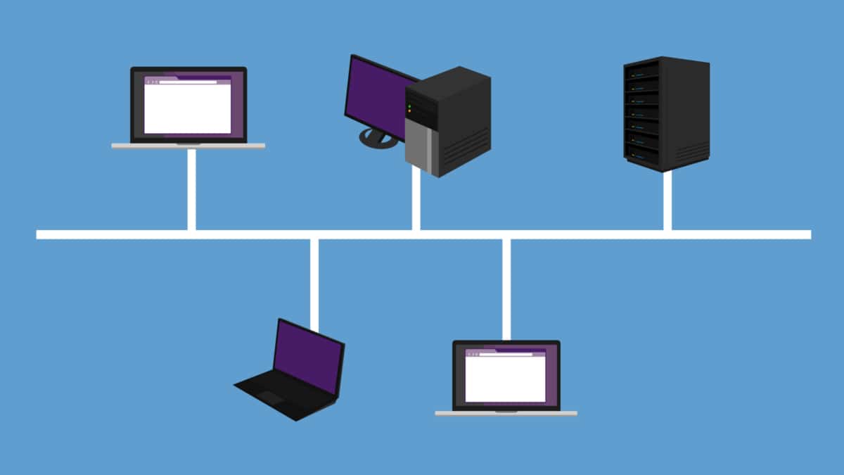
a) Bus Topology: In this traditional topology, all devices are connected linearly to a common backbone, resembling a bus. While it is simple and cost-effective, a single point of failure can disrupt the entire network.
b) Star Topology: Each device is connected directly to a central switch or hub in a star topology. This design offers centralized control and easy troubleshooting, but it can be expensive due to the requirement of additional cabling.
c) Mesh Topology: A mesh topology provides redundant connections between devices, forming a network where every device is connected to every other device. This design ensures high fault tolerance and scalability but can be complex and costly.
d) Hybrid Topology: As the name suggests, a hybrid topology combines elements of different topologies to meet specific requirements. It offers flexibility and allows organizations to optimize their infrastructure based on their unique needs.
**Considerations in Data Center Topology Design**
a) Redundancy: Redundancy is essential to ensure continuous operation even during component failures. By implementing redundant paths, power sources, and network links, data centers can minimize the risk of downtime and data loss.
b) Scalability: As the data center’s requirements grow, the topology should be able to accommodate additional devices and increased data traffic. Scalability can be achieved through modular designs, virtualization, and flexible network architectures.
c) Performance and Latency: The distance between devices, the quality of network connections, and the efficiency of routing protocols significantly impact data center performance and latency. Optimal topology design considers these factors to minimize delays and ensure smooth data transmission.
Google Cloud NCC
### What is Google Network Connectivity Center?
Google NCC is a centralized platform that provides a holistic view of your network infrastructure. It integrates with Google Cloud, enabling businesses to manage their global networks with ease. The platform is built to support hybrid and multi-cloud environments, ensuring that your data center operations are streamlined and efficient.

### Key Features and Benefits
#### Unified Network Management
One of the standout features of Google NCC is its ability to consolidate various network management tasks into a single interface. This means less time spent juggling multiple tools and more time focusing on core business activities.
#### Enhanced Security
Security is a critical concern for any organization. Google NCC incorporates robust security measures, including end-to-end encryption and advanced threat detection, to safeguard your network against potential risks.
#### Scalability and Flexibility
As your business grows, so does your need for a scalable network solution. Google NCC offers unparalleled scalability, allowing you to expand your network infrastructure effortlessly. Its flexibility ensures that it can adapt to the ever-changing demands of your business.
### Integrating with Data Centers
Google NCC is designed to seamlessly integrate with your existing data centers. This integration ensures that you can manage your on-premises and cloud-based resources from a single platform. The result is a more cohesive and efficient network management experience.


### Real-World Applications
#### Enterprise Connectivity
For large enterprises, managing a sprawling network can be a daunting task. Google NCC simplifies this by providing a unified platform that can handle complex network topologies. This makes it easier to connect multiple branch offices, remote workers, and cloud services.
#### Optimized Performance
Google NCC leverages advanced algorithms to optimize network performance. This ensures that your applications run smoothly and that data is transmitted efficiently. Whether you’re running a global e-commerce site or a high-demand application, NCC has you covered.
Impact of Data Center Topology:
Efficient data center topology directly influences the entire infrastructure’s reliability, availability, and performance. A well-designed topology reduces single points of failure, enables load balancing, enhances fault tolerance, and optimizes data flow. It directly impacts the user experience, especially for cloud-based services, where data centers simultaneously cater to many users.
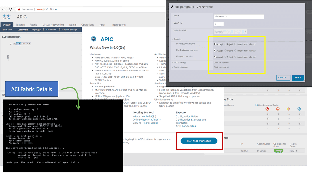
Knowledge Check: Cisco ACI Building Blocks
Before Cisco ACI 4.1, the Cisco ACI fabric supported only a two-tier (leaf-and-spine switch) topology in which leaf switches are connected to spine switches without interconnecting them. Starting with Cisco ACI 4.1, the Cisco ACI fabric allows multitier (three-tier) fabrics and two tiers of leaf switches, allowing vertical expansion. As a result, a traditional three-tier aggregation access architecture can be migrated, which is still required for many enterprise networks.
In some situations, building a full-mesh two-tier fabric is not ideal due to the high cost of fiber cables and the limitations of cable distances. A spine-leaf topology is more efficient in these cases, and Cisco ACI continues to automate and improve visibility.
Choosing a topology
Data centers are the backbone of many businesses, providing the necessary infrastructure to store and manage data and access applications and services. As such, it is essential to understand the different types of available data center topologies.
When choosing a topology for a data center, the organization’s specific needs and requirements must be considered. Each topology offers its advantages and disadvantages, so it is crucial to understand the pros and cons of each before making a decision.
A data center topology refers to the physical layout and interconnection of network devices within a data center. It determines how servers, switches, routers, and other networking equipment are connected, ensuring efficient and reliable data transmission. Topologies are based on scalability, fault tolerance, performance, and cost.
Scalability of the topology
Additionally, it is essential to consider the topology’s scalability, as a data center may need to accommodate future growth. By understanding the different topologies and their respective strengths and weaknesses, organizations can make the best decision for their data centers. For example, in a spine-and-leaf architecture, traffic traveling from one server to another always crosses the same number of devices (unless both servers are located on the same leaf). Payloads need only hop to a spine switch and another leaf switch to reach their destination, thus reducing latency.
Data Center Topology Types
Centralized Model
Smaller data centers (less than 5,000 square feet) may benefit from the centralized model. It is shown that there are separate local area networks (LANs) and storage area networks (SANs), with home-run cables going to each server cabinet and zone. Each server is effectively connected back to the core switches in the main distribution area.
As a result, port switches can be utilized more efficiently, and components can be managed and added more quickly. The centralized topology works well for smaller data centers but does not scale up well, making expansion difficult. Many cable runs in larger data centers cause cable pathways and cabinets congestion and increase costs.
Zoned or top-of-rack topologies may be used in large data centers for LAN traffic, but centralized architectures may be used for SAN traffic. In particular, port utilization is essential when SAN switch ports are expensive.
Zoned Topology
Distributed switching resources make up a zoned topology. Typically, chassis-based switches support multiple server cabinets and can be distributed among end-of-row (EoR) and middle-of-row (MoR) locations. It is highly scalable, repeatable, and predictable and is recommended by the ANS/TIA-942 Data Center Standards.
A zoned architecture provides the highest switch and port utilization level while minimizing cabling costs. Switching at the end of a row can be advantageous in certain situations. Two servers’ local area network (LAN) ports can be connected to the same end-of-row switch for low-latency port-to-port switching.
Having to run cable back to the end-of-row switch is a potential disadvantage of end-of-row switching. It is possible for this cabling to exceed that required for a top-of-rack system if every server is connected to redundant switches.
Top-of-rack (ToR)
Switches are typically placed at the top of a server rack to provide top-of-rack (ToR) switching, as shown below. Using this topology is a good option for dense one-rack-unit (1RU) server environments. For redundancy, both switches are connected to all servers in the rack. There are uplinks to the next layer of switching from the top-of-rack switches.
It simplifies cable management and minimizes cable containment requirements when cables are managed at the top of the rack. Using this approach, servers within the rack can quickly switch from port to port, and the uplink oversubscription is predictable.
In top-of-rack designs, cabling is more efficiently utilized. In exchange, there is usually an increase in the cost of switches and a high cost for under-utilization of ports. There is also the possibility of overheating local area network (LAN) switch gear in server racks when top-of-rack switching is required.
Data Center Architecture Types
Mesh architecture
Mesh networks, known as “network fabrics” or leaf-spine, consist of meshed connections between leaf-and-spine switches. They are well suited for supporting universal “cloud services” because the mesh of network links enables any-to-any connectivity with predictable capacity and lower latency. The mesh network has multiple switching resources scattered throughout the data center, making it inherently redundant. Compared to huge, centralized switching platforms, these distributed network designs can be more cost-effective to deploy and scale.
Multi-Tier
Multi-tier architectures are commonly used in enterprise data centers. In this design, mainframes, blade servers, 1RU servers, and mainframes run the web, application, and database server tiers.
Mesh point of delivery
Mesh point of delivery (PoD) architectures have leaf switches interconnected within PoDs, and spine switches aggregated in a central main distribution area (MDA). This architecture also enables multiple PoDs to connect efficiently to a super-spine tier. Three-tier topologies that support east-west data flows will be able to support new cloud applications with low latency. Mesh PoD networks can provide a pool of low-latency computing and storage for these applications that can be added without disrupting the existing environment.
Super Spine architectecutre
Hyperscale organizations that deploy large-scale data center infrastructures or campus-style data centers often deploy super spine architecture. This type of architecture handles data passing east to west across data halls.
Cloud Data Centers
Understanding Network Tiers
Network tiers refer to the different levels of service quality and performance that a network can offer. They allow businesses to prioritize and allocate resources based on their specific needs. In the case of Google Cloud, there are two primary network tiers: Premium Tier and Standard Tier.
The Premium Tier in Google Cloud offers businesses a top-of-the-line network experience. It leverages Google’s private global network, which is interconnected with major internet service providers (ISPs) worldwide.
This interconnectivity ensures low latency, high bandwidth, and enhanced reliability for mission-critical workloads. By utilizing the Premium Tier, businesses can deliver an exceptional user experience, reduce downtime, and ensure optimal performance for latency-sensitive applications.
While the Premium Tier provides unparalleled performance, the Standard Tier offers a more cost-effective alternative for businesses with less latency-sensitive workloads. The Standard Tier leverages public internet transit, providing reliable and secure connectivity at a lower price point.
This tier is ideal for applications that can tolerate slightly higher latency, such as batch processing, non-real-time analytics, or backup and recovery tasks. By utilizing the Standard Tier, businesses can achieve significant cost savings without sacrificing overall network reliability.


Understanding VPC Networking
VPC networking forms the foundation of your cloud infrastructure, allowing you to create and manage virtual networks with ease. In Google Cloud, VPC networks provide isolation and connectivity for your resources, ensuring secure communication and data transfer.

Google Cloud’s VPC networking offers a plethora of powerful features. These include custom IP ranges, subnets, firewall rules, routes, and VPN connectivity. Custom IP ranges enable you to define IP addresses for your virtual network, while subnets allow you to divide your network into smaller segments for better organization and control.


Understanding VPC Peering
VPC Peering is a networking arrangement that enables communication between two virtual private clouds (VPCs) in the same or different projects within Google Cloud. It establishes a direct, private connection between VPC networks, allowing them to communicate as if they were part of the same network.

VPC Peering offers numerous benefits to organizations leveraging Google Cloud. First, it enables seamless and secure communication between VPC networks, eliminating the need for complex VPN setups or publicly exposing resources. Second, it allows for low-latency data transfer, ensuring optimal performance for applications and services. Third, it simplifies network management, enabling centralized administration of connected VPCs.

Related: For pre-information, you may find the following post helpful
The Role of Networks
A network lives to serve the connectivity requirements of applications and applications. We build networks by designing and implementing data centers. A common trend is that the data center topology is much bigger than a decade ago, with application requirements considerably different from the traditional client-server applications and with deployment speeds in seconds instead of days. This changes how networks and your chosen data center topology are designed and deployed.
The traditional network design was scaled to support more devices by deploying larger switches (and routers). This is the scale-in model of scaling. However, these large switches are expensive and primarily designed to support only a two-way redundancy.
Today, data center topologies are built to scale out. They must satisfy the three main characteristics of increasing server-to-server traffic, scale ( scale on-demand ), and resilience. The following diagram shows a ToR design we discussed at the start of the blog.
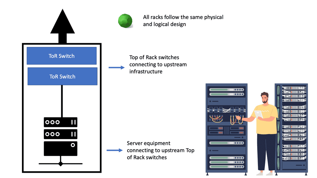
The Role of The ToR
Top of rack (ToR) is a term used to describe the architecture of a data center. It is a server architecture in which servers, switches, and other equipment are mounted on the same rack. This allows for the most efficient use of space since the equipment is all within arm’s reach.
ToR is also the most efficient way to manage power and cooling since the equipment is all in the same area. Since all the equipment is close together, ToR also allows faster access times. This architecture can also be utilized in other areas, such as telecommunications, security, and surveillance.
ToR is a great way to maximize efficiency in any data center and is becoming increasingly popular. In contrast to the ToR data center design, the following diagram shows an EoR switch design.
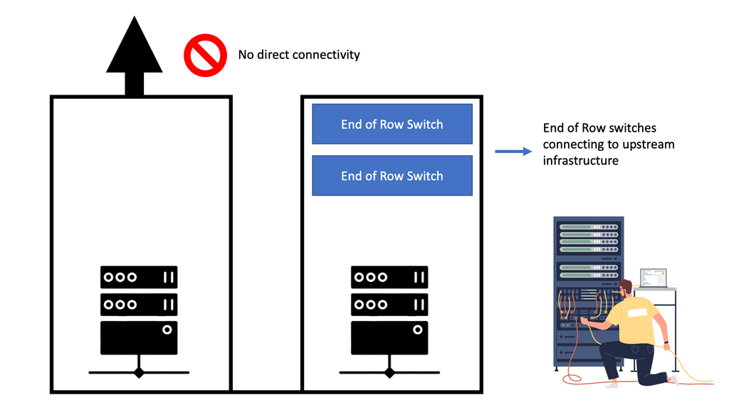
The Role of The EoR
The term end-of-row (EoR) design is derived from a dedicated networking rack or cabinet placed at either end of a row of servers to provide network connectivity to the servers within that row. In EoR network design, each server in the rack has a direct connection with the end-of-row aggregation switch, eliminating the need to connect servers directly with the in-rack switch.
Racks are usually arranged to form a row; a cabinet or rack is positioned at the end of this row. This rack has a row aggregation switch, which provides network connectivity to servers mounted in individual racks. This switch, a modular chassis-based platform, sometimes supports hundreds of server connections. However, a large amount of cabling is required to support this architecture.
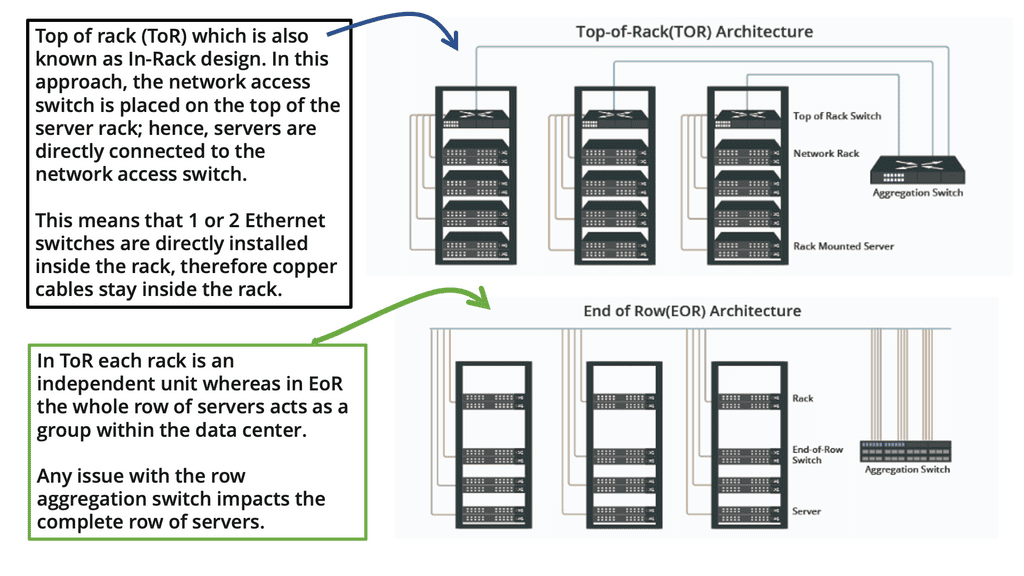
A ToR configuration requires one switch per rack, resulting in higher power consumption and operational costs. Moreover, unused ports are often more significant in this scenario than with an EoR arrangement.
On the other hand, ToR’s cabling requirements are much lower than those of EoR, and faults are primarily isolated to a particular rack, thus improving the data center’s fault tolerance.
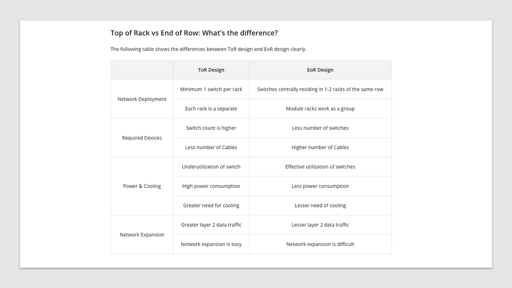
If fault tolerance is the ultimate goal, ToR is the better choice, but EoR configuration is better if an organization wants to save on operational costs. The following table lists the differences between a ToR and an EoR data center design.
Data Center Topology Types:
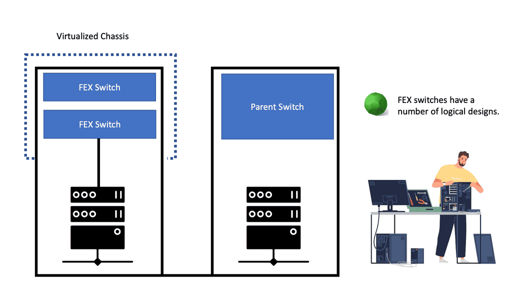
Fabric extenders – FEX
Cisco has introduced the concept of Fabric Extenders, which are not Ethernet switches but remote line cards of a virtualized modular chassis ( parent switch ). This allows scalable topologies previously impossible with traditional Ethernet switches in the access layer.
You should relate an FEX device like a remote line card attached to a parent switch. All the configuration is done on the parent switch, yet physically, the fabric extender could be in a different location. The mapping between the parent switch and the FEX ( fabric extender ) is done via a special VN-Link.
The following diagram shows an example of a FEX in a standard data center network topology. More specifically, we are looking at the Nexus 2000 FEX Series. Cisco Nexus 2000 Series Fabric Extenders (FEX) are based on the standard IEEE 802.1BR. They deliver fabric extensibility with a single point of management.
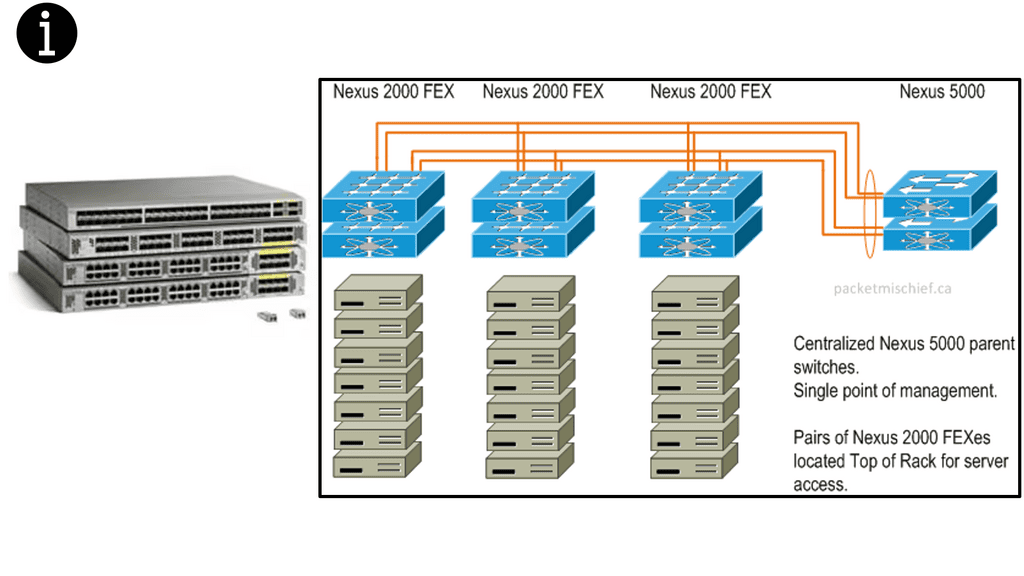
Different types of Fex solution
FEXs come with various connectivity solutions, including 100 Megabit Ethernet, 1 Gigabit Ethernet, 10 Gigabit Ethernet ( copper and fiber ), and 40 Gigabit Ethernet. They can be synchronized with the following parent switch models: Nexus 5000, Nexus 6000, Nexus 7000, Nexus 9000, and Cisco UCS Fabric Interconnect.
In addition, because of FEX’s simplicity, they have very low latency ( as low as 500 nanoseconds ) compared to traditional Ethernet switches.
Some network switches can be connected to others and operate as a single unit. These configurations are called “stacks” and are helpful for quickly increasing the capacity of a network. A stack is a network solution composed of two or more stackable switches. Switches that are part of a stack behave as one single device.
Traditional switches like the 3750s still stand in the data center network topology access layer and can be used with stacking technology, combining two physical switches into one logical switch.
This stacking technology allows you to build a highly resilient switching system, one switch at a time. If you are looking at a standard access layer switch like the 3750s, consider the next-generation Catalyst 3850 series.
The 3850 supports BYOD/mobility and offers various performance and security enhancements compared to previous models. However, stacking has a drawback: You can only stack several switches. So, if you want more throughout, you should aim for a different design type.
Data Center Design: Layer 2 and Layer 3 Solutions
Traditional views of data center design
Depending on the data center network topology deployed, packet forwarding at the access layer can be either Layer 2 or Layer 3. A Layer 3 approach would involve additional management and configuring IP addresses on hosts in a hierarchical fashion that matches the switch’s assigned IP address.
An alternative approach is to use Layer 2, which has less overhead as Layer 2 MAC addresses do not need specific configuration. However, it has drawbacks with scalability and poor performance.
Generally, access switches focus on communicating servers in the same IP subnet, allowing any type of traffic – unicast, multicast, or broadcast. You can, however, have filtering devices such as a Virtual Security Gateway ( VSG ) to permit traffic between servers, but that is generally reserved for inter-POD ( Platform Optimized Design ) traffic.
Leaf and Spine With Layer 3
We use a leaf and spine data center design with Layer 3 everywhere and overlay networking. This modern, robust architecture provides a high-performance, highly available network. With this architecture, data center networks are composed of leaf switches that connect to one or more spine switches.
The leaf switches are connected to end devices such as servers, storage devices, and other networking equipment. The spine switches, meanwhile, act as the network’s backbone, connecting the multiple leaf switches.
The leaf and spine architecture provides several advantages over traditional data center networks. It allows for greater scalability, as additional leaf switches can be easily added to the network. It also offers better fault tolerance, as the network can operate even if one of the spine switches fails.
Furthermore, it enables faster traffic flows, as the spine switches to route traffic between the leaf switches faster than a traditional flat network.
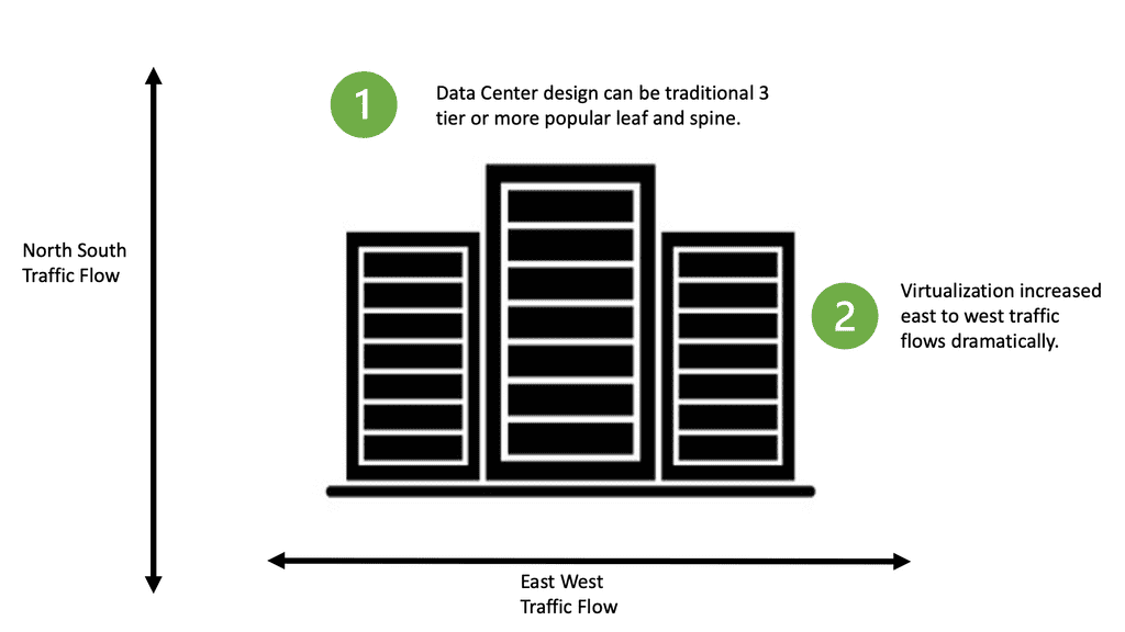
Data Center Traffic Flow
Datacenter topologies can have North-South or East-to-West traffic. North-south ( up / down ) corresponds to traffic between the servers and the external world ( outside the data center ). East-to-west corresponds to internal server communication, i.e., traffic does not leave the data center.
Therefore, determining the type of traffic upfront is essential as it influences the type of topology used in the data center.
For example, you may have a pair of ISCSI switches, and all traffic is internal between the servers. In this case, you would need high-bandwidth inter-switch links. Usually, an ether channel supports all the cross-server talk; the only north-to-south traffic would be management traffic.
In another part of the data center, you may have data server farm switches with only HSRP heartbeat traffic across the inter-switch links and large bundled uplinks for a high volume of north-to-south traffic. Depending on the type of application, which can be either outward-facing or internal, computation will influence the type of traffic that will be dominant.
Virtual Machine and Containers.
This drive was from virtualization, virtual machines, and container technologies regarding east-west traffic. Many are moving to a leaf and spine data center design if they have a lot of east-to-west traffic and want better performance.
Network Virtualization and VXLAN
Network virtualization and the ability of a physical server to host many VMs and move those VMs are also used extensively in data centers, either for workload distribution or business continuity. This will also affect the design you have at the access layer.
For example, in a Layer 3 fabric, migrating a VM across that boundary changes its IP address, resulting in a reset of the TCP sessions because, unlike SCTP, TCP does not support dynamic address configuration. In a Layer 2 fabric, migrating a VM incurs ARP overhead and requires forwarding on millions of flat MAC addresses, which leads to MAC scalability and poor performance problems.
VXLAN: stability over Layer 3 core
Network virtualization plays a vital role in the data center. Technologies like VXLAN attempt to move the control plane from the core to the edge and stabilize the core so that it only has a handful of addresses for each ToR switch. The following diagram shows the ACI networks with VXLAN as the overlay that operates over a spine leaf architecture.
Layer 2 and 3 traffic is mapped to VXLAN VNIs that run over a Layer 3 core. The Bridge Domain is for layer 2, and the VRF is for layer 3 traffic. Now, we have the separation of layer 2 and 3 traffic based on the VNI in the VXLAN header.
One of the first notable differences between VXLAN and VLAN was scale. VLAN has a 12-bit identifier called VID, while VXLAN has a 24-bit identifier called a VID network identifier. This means that with VLAN, you can create only 4094 networks over ethernet, while with VXLAN, you can create up to 16 million.
Whether you can build layer 2 or layer 3 in the access and use VXLAN or some other overlay to stabilize the core, it would help if you modularized the data center. The first step is to build each POD or rack as a complete unit. Each POD will be able to perform all its functions within that POD.
- A key point: A POD data center design
POD is a design methodology that aims to simplify, speed deployment, optimize resource utilization, and drive the interoperability of three or more data center components: server, storage, and networks.
- A POD example: Data center modularity
For example, one POD might be a specific human resources system. The second is modularity based on the type of resources offered. For example, a storage pod or bare metal compute may be housed in separate pods.
These two modularization types allow designers to easily control inter-POD traffic with predefined policies. Operators can also upgrade PODs and a specific type of service at once without affecting other PODs.
However, this type of segmentation does not address the data center’s scale requirements. Even when we have adequately modularized the data center into specific portions, the MAC table sizes on each switch still increase exponentially as the data center grows.
Current and Future Design Factors
New technologies with scalable control planes must be introduced for a cloud-enabled data center, and these new control planes should offer the following:
Option Data Center Feature Data center feature 1 The ability to scale MAC addresses Data center feature 2 First-Hop Redundancy Protocol ( FHRP ) multipathing and Anycast HSRP Data center feature 3 Equal-Cost multipathing Data center feature 4 MAC learning optimizations
Several design factors need to be considered when designing a data center. First, what is the growth rate for servers, switch ports, and data center customers? This prevents part of the network topology from becoming a bottleneck or linking congested.
**Application bandwidth demand?**
This demand is usually translated into oversubscription. In data center networking, oversubscription refers to how much bandwidth switches are offered to downstream devices at each layer.
Oversubscription is expected in a data center design. Limiting oversubscription to the ToR and edge of the network offers a single place to start when performance problems occur.
A data center with no oversubscription ratio will be costly, especially with a low latency network design. So, it’s best to determine what oversubscription ratio your applications support and work best. Optimizing your switch buffers to improve performance is recommended before you decide on a 1:1 oversubscription rate.
**Ethernet 6-byte MAC addressing is flat**
Ethernet forms the basis of data center networking in tandem with IP. Since its inception 40 years ago, Ethernet frames have been transmitted over various physical media, even barbed wire. Ethernet 6-byte MAC addressing is flat; the manufacturer typically assigns the address without considering its location.
Ethernet-switched networks do not have explicit routing protocols to ensure readability about the flat addresses of the server’s NICs. Instead, flooding and address learning are used to create forwarding table entries.
**IP addressing is a hierarchy**
On the other hand, IP addressing is a hierarchy, meaning that its address is assigned by the network operator based on its location in the network. A hierarchy address space advantage is that forwarding tables can be aggregated. If summarization or other routing techniques are employed, changes in one side of the network will not necessarily affect other areas.
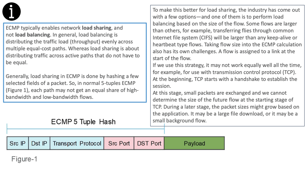
This makes IP-routed networks more scalable than Ethernet-switched networks. IP-routed networks also offer ECMP techniques that enable networks to use parallel links between nodes without spanning tree disabling one of those links. The ECMP method hashes packet headers before selecting a bundled link to avoid out-of-sequence packets within individual flows.
Equal Cost Load Balancing
Equal-cost load balancing is a method for distributing network traffic among multiple paths of equal cost. It provides redundancy and increases throughput. Sending traffic over numerous paths avoids congestion on any single link. In addition, the load is equally distributed across the paths, meaning that each path carries roughly the same total traffic.
This allows for using multiple paths at a lower cost, providing an efficient way to increase throughput.
The idea behind equal-cost load balancing is to use multiple paths of equal cost to balance the load on each path. The algorithm considers the number of paths, each path’s weight, and each path’s capacity. It also considers the number of packets that must be sent and the delay allowed for each packet.
Considering these factors, it can calculate the best way to distribute the load among the paths.
Equal-cost load balancing can be implemented using various methods. One method is to use a Link Aggregation Protocol (LACP), which allows the network to use multiple links and distribute the traffic among the links in a balanced way.
- A keynote: Data center topologies. The move to VXLAN.
Given the above considerations, a solution encompassing the benefits of L2’s plug-and-play flat addressing and IP scalability is needed. Location-Identifier Split Protocol ( LISP ) has a set of solutions that use hierarchical addresses as locators in the core and flat addresses as identifiers in the edges. However, not much is seen in its deployment these days.
Equivalent approaches such as THRILL and Cisco FabricPath create massive scalable L2 multipath networks with equidistant endpoints. Tunneling is also being used to extend down to the server and access layer to overcome the 4K limitation with traditional VLANs. What is VXLAN? Tunneling with VXLAN is now the standard design in most data center topologies with leaf-spine designs. The following video provides VXLAN guidance.
Data Center Network Topology
Leaf and spine data center topology types
This is commonly seen in a leaf and spine design. For example, in a leaf-spine fabric, We have a Layer 3 IP fabric that supports equal-cost multi-path (ECMP) routing between any two endpoints in the network. Then, on top of the Layer 3 fabric is an overlay protocol, commonly VXLAN.
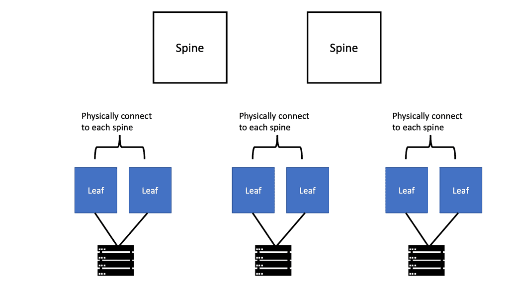
A spine-leaf architecture consists of a data center network topology with two switching layers: a spine and a leaf. The leaf layer comprises access switches that aggregate traffic from endpoints such as servers and connect directly to the spine or network core.
Spine switches interconnect all leaf switches in a full-mesh topology. The leaf switches do not directly connect. The Cisco ACI is a data center topology that utilizes the leaf and spine.
The ACI network’s physical topology is a leaf and spine, while the logical topology is formed with VXLAN. From a protocol side point, VXLAN is the overlay network, and the BGP and IS-IS provide the Layer 3 routing, the underlay network that allows the overlay network to function.
As a result, the nonblocking architecture performs much better than the traditional data center design based on access, distribution, and core designs.
**Closing Points: Data Center Topologies**
A data center topology refers to the physical layout and interconnection of network devices within a data center. It determines how servers, switches, routers, and other networking equipment are connected, ensuring efficient and reliable data transmission. Topologies are based on scalability, fault tolerance, performance, and cost.
- Hierarchical Data Center Topology:
The hierarchical or tree topology is one of the most commonly used data center topologies. This design consists of multiple core, distribution, and access layers. The core layer connects all the distribution layers, while the distribution layer connects to the access layer. This structure enables better management, scalability, and fault tolerance by segregating traffic and minimizing network congestion.
- Mesh Data Center Topology:
Every network device is interlinked in a mesh topology, forming a fully connected network with multiple paths for data transmission. This redundancy ensures high availability and fault tolerance. However, this topology can be cost-prohibitive and complex, especially in large-scale data centers.
- Leaf-Spine Data Center Topology:
The leaf-spine topology is gaining popularity due to its scalability and simplicity. It consists of interconnected leaf switches at the access layer and spine switches at the core layer. This design allows for non-blocking, low-latency communication between any leaf switch and spine switch, making it suitable for modern data center requirements.
- Full-Mesh Data Center Topology:
As the name suggests, the full-mesh topology connects every network device to every other device, creating an extensive web of connections. This topology offers maximum redundancy and fault tolerance. However, it can be expensive to implement and maintain, making it more suitable for critical applications with stringent uptime requirements.

- DMVPN - May 20, 2023
- Computer Networking: Building a Strong Foundation for Success - April 7, 2023
- eBOOK – SASE Capabilities - April 6, 2023