Interconnecting Devices
Interconnecting various components of a network is an extensive and comprehensive process. At a base level, network components can be connected via switches, gateways, and routers. Efficient and reliable network connectivity indicates how well these components interact, either on-premises or a cloud-based network. As a result of network connectivity, a range of devices, including IoT and computers can communicate with one another via protocols and other methods, facilitating connectivity.
To understand network connectivity, we will break networking down into layers. Then, we can fit the different networking and security components that make up a network into each layer. This is the starting point for understanding how networks work and carrying out the advanced stages of network design, and troubleshooting.
Networking does not just magically happen; we need to follow protocols and rules so that two endpoints can communicate and share information. These rules and protocols don’t just exist on the endpoint, such as your laptop; they also need to exist on the network and security components in the path between the two endpoints.
**TCP/IP Suite and OSI Model**
We have networking models, such as the TCP/IP Suite and the OSI model, to help you understand what rules and protocols we need for all components. These networking models are like blueprints for building a house. They allow you to follow specific patterns and have certain types of people, which are protocols in networking.
**Address Resolution Protocol (ARP)**
For example, when you know the destination’s IP address, you use the Address Resolution Protocol (ARP) to find the MAC address. So, we have rules and standards to follow. By learning these rules, you can install, configure, and troubleshoot the main networking components of routers, switches, and security devices.
Networking Components
Routers are vital in directing network traffic and ensuring data packets reach their destinations. They act as intermediaries between different networks, using routing tables to determine the best path for data transmission. With their advanced features, such as Quality of Service (QoS) and firewall capabilities, routers provide a secure and efficient network connection. Routers are responsible for directing traffic between different networks and keeping them isolated.
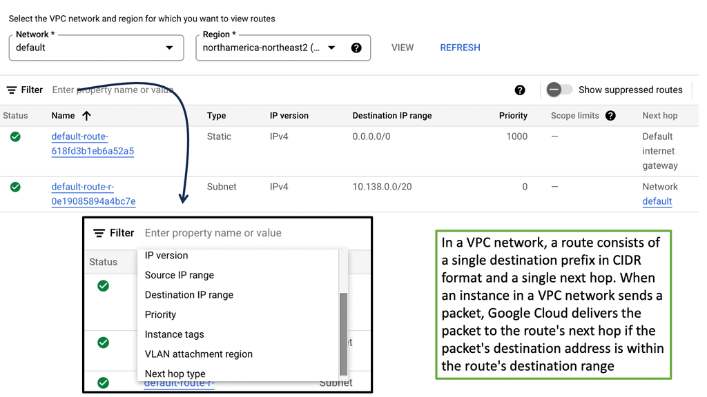
Example Routing Technology: VPC Networking
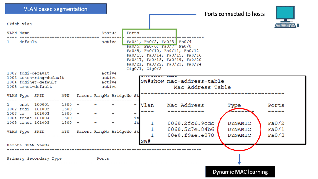
Switches enable the interconnection of devices within a local network. They operate at the data link layer of the OSI model, using MAC addresses to forward data packets to the intended recipient. By creating virtual LANs (VLANs) and managing network traffic effectively, switches enhance network performance and provide seamless communication between devices.
Firewalls act as the first line of defense against unauthorized access to a network. These security devices monitor incoming and outgoing network traffic based on predetermined rules, allowing or blocking data packets accordingly. By implementing firewalls, organizations can prevent potential threats and maintain control over their network’s security posture.
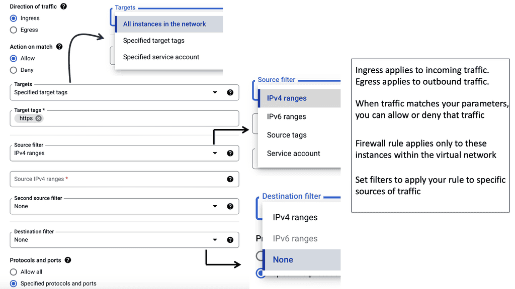
Example Distributed Firewall Technology: Tagging Options
Intrusion Detection Systems (IDS) are designed to identify and respond to potential security breaches. They monitor network traffic, looking for signs of malicious activity or unauthorized access attempts. IDS can be host- or network-based, providing real-time alerts and helping network administrators promptly mitigate potential threats.
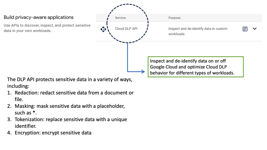
Example DLP Technology: Cloud DLP API
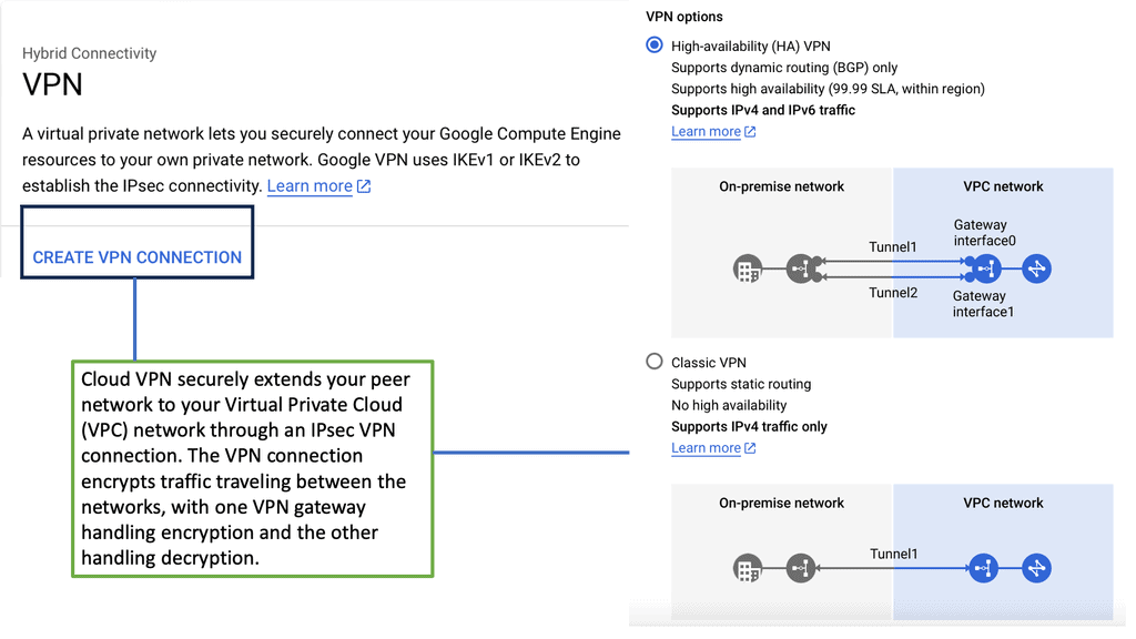
 Virtual Private Networks (VPNs) establish encrypted tunnels over public networks, allowing remote users to access company resources securely. By encrypting data, VPNs provide confidentiality and integrity, ensuring that sensitive information remains protected during transmission.
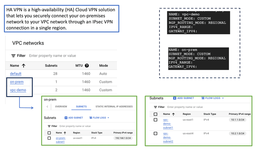
Example VPN Technology: Google HA VPN
Access Control Systems ensure only authorized personnel can access sensitive data and resources. This includes various authentication mechanisms such as passwords, biometrics, or smart cards. Organizations can significantly reduce the risk of unauthorized access to critical systems or information by implementing access control systems.
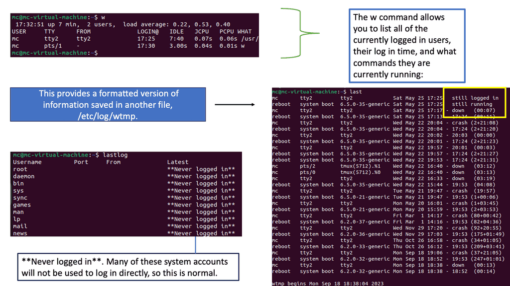
Example Access Control: Linux Access Controls
Creating Boundaries for Secure Network Connectivity
One way to create the boundary between the external and internal networks is with a firewall. An example would be a Cisco ASA firewall configured with zones. The zones create the border. Example: Gig0/0 is the internal zone with a security level of 0. By default, a higher-level area, such as the outside zone, with a security level of 100, cannot communicate with zones of lower numbering.
Security zones are virtual boundaries created within your network infrastructure to control and monitor traffic flow. These zones provide an added layer of defense, segregating different network segments based on their trust levels. Administrators can apply specific security policies and access controls by classifying traffic into zones, reducing the risk of unauthorized access or malicious activities.
So, as I said, computer networks enable connected hosts—computers—to share and access resources. So when you think of a network, think of an area, and this area exists for sharing. The first purpose of network connectivity was to share printers, and it has not been expanded to many other devices to share, but in reality, the use case of sharing is still its primary use case.
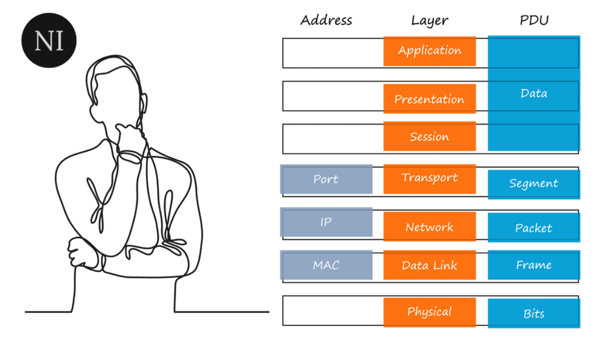
You need to know how all the connections happen and all the hardware and software that enables that exchange of resources. We do this using a networking model. So, we can use network models to conceptualize the many parts of a network, relying primarily on the Open Systems Interconnection (OSI) seven-layer model to help you understand networking.
Remember that we don’t implement the OSI; we implement the TCP/IP suite. However, the OSI is a great place to start learning, as everything is divided into individual layers. You can place the network and security components at each layer to help you understand how networks work. Let us start with the OSI model before we move to the TCP/IP suite.
IPv4 and IPv6 Connectivity
Understanding IPv4 & IPv6 Connectivity:
IPv4, or Internet Protocol version 4, is the fourth iteration of the IP protocol. It uses a 32-bit address space, allowing for approximately 4.3 billion unique addresses. This version has been the foundation of internet connectivity for several decades and has served us well. However, with the rapid growth of internet-connected devices, the limitations of IPv4 have become apparent.
Enter IPv6, or Internet Protocol version 6, the next generation of IP addressing. IPv6 was designed to address the limitations of IPv4 by utilizing a 128-bit address space, resulting in a staggering number of unique addresses – approximately 340 undecillion! This vast expansion of address space ensures that we will not run out of addresses anytime soon, even with the increasing number of internet-connected devices.
IPv6 Advantages:
IPv6 offers several advantages over its predecessor. First, its larger address space allows for efficient and scalable allocation of IP addresses, ensuring that every device can have a unique identifier. Second, IPv6 incorporates built-in security features, enhancing the integrity and confidentiality of data transmitted over the network. Third, IPv6 supports auto-configuration, simplifying the process of connecting devices to a network.
Challenge- Transitioning to IPv6:
While IPv6 brings numerous benefits, transitioning from IPv4 to IPv6 has challenges. One of the main obstacles lies in the coexistence of the two protocols during the transition phase. However, various transition mechanisms, such as dual-stack, tunneling, and translation, have been developed to enable interoperability between IPv4 and IPv6 networks. These mechanisms facilitate a smooth transition, ensuring that devices and networks communicate seamlessly.
IPv6 Connectivity & Solicited Node Address
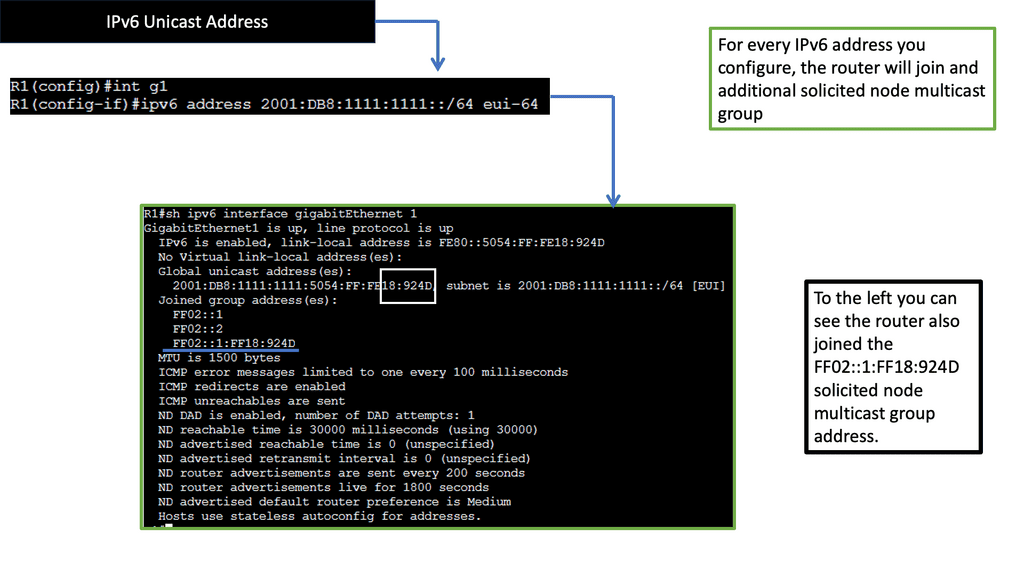
The Purpose of Solicited Node Multicast Address
Now that we have a basic understanding of multicast communication, let’s explore the purpose of IPv6 Solicited Node Multicast Address. Its primary function is to enable efficient address resolution for devices in an IPv6 network. When a device wants to resolve the Layer 2 address (MAC address) of another device with a known IPv6 address, it can use the Solicited Node Multicast Address to send a request to a specific group of devices that share the same IPv6 address prefix.
Structure & Format
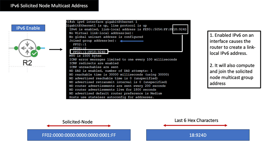
IPv6 Solicited Node Multicast Address has a unique and structured format. It is derived from the device’s IPv6 address by replacing the least significant 24 bits with a specific prefix (FF02::1:FF/104) and the last 24 bits with the corresponding bits from the original IPv6 address. This ensures that the resulting multicast address is unique to the device while being part of the larger multicast group associated with that particular IPv6 address.
Neighbor Discovery Protocol (NDP) is a crucial aspect of IPv6 network operations, and IPv6 Solicited Node Multicast Address plays a vital role within this protocol. When a device joins an IPv6 network, it uses the Solicited Node Multicast Address to send a Neighbor Solicitation message to the group associated with its IPv6 address. This message serves as a request to obtain the device’s MAC address with the corresponding IPv6 address, allowing for efficient communication and address resolution.
IPv6 Neighbor Discovery
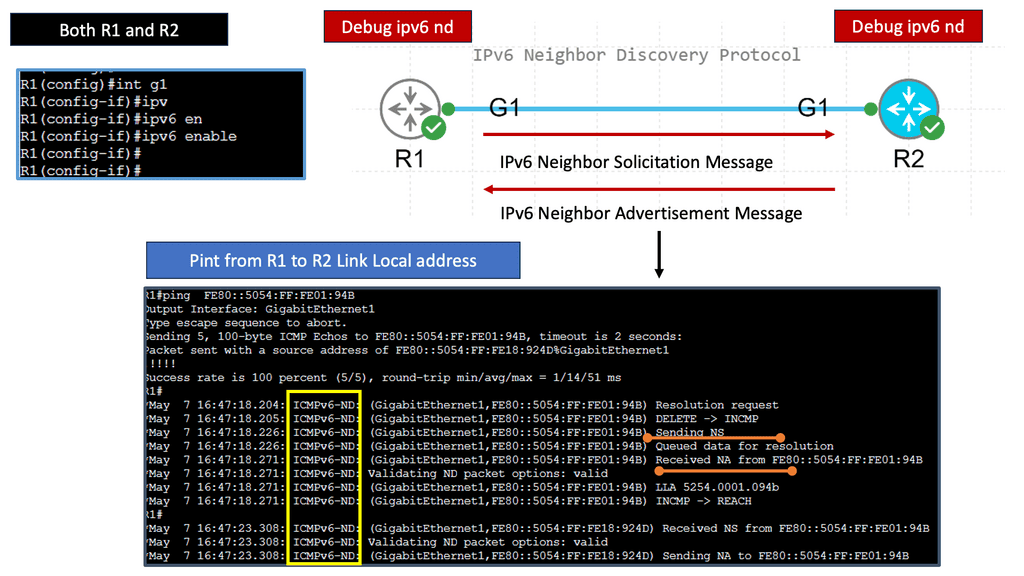
Understanding IPv6 Neighbor Discovery
IPv6 Neighbor Discovery Protocol, often abbreviated as NDP, serves as a key mechanism in the IPv6 network for various tasks such as address autoconfiguration, duplicate address detection, and router discovery. It replaces the functions performed by the Address Resolution Protocol (ARP) in IPv4. Using ICMPv6 messages and multicast communication, NDP enables efficient network operations and seamless communication between neighboring devices.
A) Neighbor Solicitation and Neighbor Advertisement:
These ICMPv6 message types form the backbone of IPv6 Neighbor Discovery. Neighbor Solicitation messages are used to determine the link-layer address of a neighboring node. In contrast, Neighbor Advertisement messages provide the necessary information in response to a solicitation or as part of periodic updates.
B) Router Solicitation and Router Advertisement:
Router Solicitation and Router Advertisement messages play a vital role in facilitating the discovery of routers on the network. Nodes send Router Solicitation messages to request router configuration information, while routers periodically broadcast Router Advertisement messages to announce their presence and important network details.
The adoption of IPv6 Neighbor Discovery brings forth several advantages. Firstly, it simplifies the configuration process by allowing devices to assign IPv6 addresses automatically without manual intervention. This enables efficient scalability and reduces administrative overhead. NDP’s neighbor caching mechanism also enhances network performance by storing and managing neighbor information, reducing network congestion and faster communication.
While IPv6 Neighbor Discovery offers numerous benefits, it has challenges. One of the primary concerns is the potential for malicious activities, such as Neighbor Spoofing or Neighbor Advertisement Spoofing attacks. To mitigate these risks, network administrators should implement secure network designs, leverage features like Secure Neighbor Discovery (SEND), and employ intrusion detection and prevention systems to safeguard against potential threats.

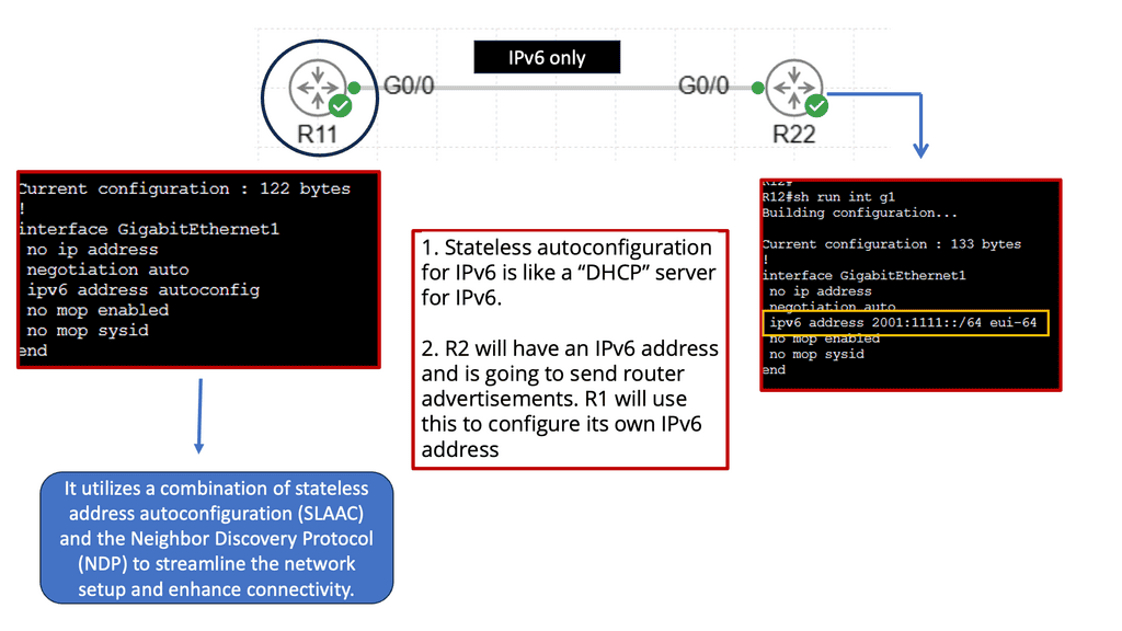
IPv6 Stateless Autoconfiguration
Stateless autoconfiguration is a mechanism in IPv6 that allows devices to assign themselves an IP address, configure their default gateway, and perform other necessary network settings without manual configuration or DHCP servers. It is based on the Neighbor Discovery Protocol (NDP) and Router Advertisement (RA) messages.
1: Efficiency and Scalability: Stateless autoconfiguration simplifies network setup, especially in large-scale deployments. It eliminates the need for manual IP address assignment, reducing the chances of human error and streamlining the process of connecting devices to the network.
Reduced Dependency on DHCP: Unlike IPv4, where DHCP is commonly used for IP address assignment, stateless autoconfiguration reduces reliance on DHCP servers. This reduces network complexity and eliminates single points of failure, leading to increased network stability.
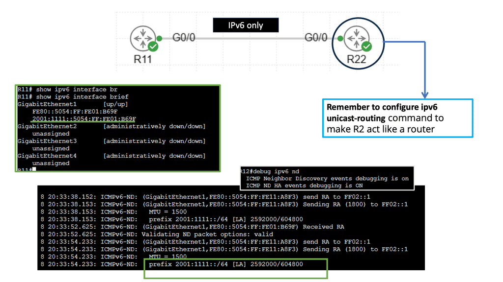
2: Seamless Network Roaming: Stateless autoconfiguration enables devices to connect seamlessly to different networks without requiring reconfiguration. This is particularly useful for mobile devices that frequently switch between networks, such as smartphones and laptops.
3: Router Advertisement (RA) Messages: Routers periodically send RA messages to announce their presence on the network and provide network configuration information. These messages contain essential details like prefixes, default gateways, and other network-related parameters.
4: Neighbor Discovery Protocol (NDP): The NDP is responsible for various functions, including address resolution, duplicate address detection, and router discovery. It plays a crucial role in stateless autoconfiguration by facilitating the assignment of IP addresses and other network settings.
Network Connectivity with Google Cloud
Understanding VPC Networking
VPC Networking serves as the backbone of a cloud infrastructure, allowing users to create and manage their own virtual network environments. It provides isolation, security, and flexibility, enabling seamless connectivity between various resources within the cloud environment. With Google Cloud’s VPC networking, organizations can have full control over their network settings, subnets, IP addresses, and routing.

Google Cloud’s VPC networking offers a robust set of features that empower users to customize and optimize their network infrastructure. Some notable features include:
1. Subnetting: Users can divide their network into subnets, enabling better organization and control over IP address allocation.
2. Firewall Rules: VPC networking allows users to define and enforce firewall rules, ensuring secure access to resources and protecting against unauthorized access.
3. Network Peering: This feature enables the connection of multiple VPC networks, allowing seamless communication between resources in different VPCs.
4. VPN Connectivity: Google Cloud’s VPC networking offers secure VPN connections, facilitating remote access and secure communication between on-premises networks and the cloud.


Understanding VPC Peering
VPC peering enables communication between VPC networks in a single region or across different regions. It establishes a direct private connection between VPCs, eliminating the need for external gateways or VPN tunnels. This direct connection ensures low-latency and high-bandwidth communication, making it ideal for inter-VPC communication.
VPC peering can be leveraged in different scenarios to meet specific requirements. One common use case is multi-tier application architectures, where different tiers of an application are deployed in separate VPCs.

VPC peering allows these tiers to communicate securely while maintaining isolation. Another use case is disaster recovery, where VPC peering facilitates data replication and synchronization between primary and secondary VPCs. Furthermore, VPC peering supports hybrid cloud deployments by enabling connectivity between on-premises networks and Google Cloud VPCs.

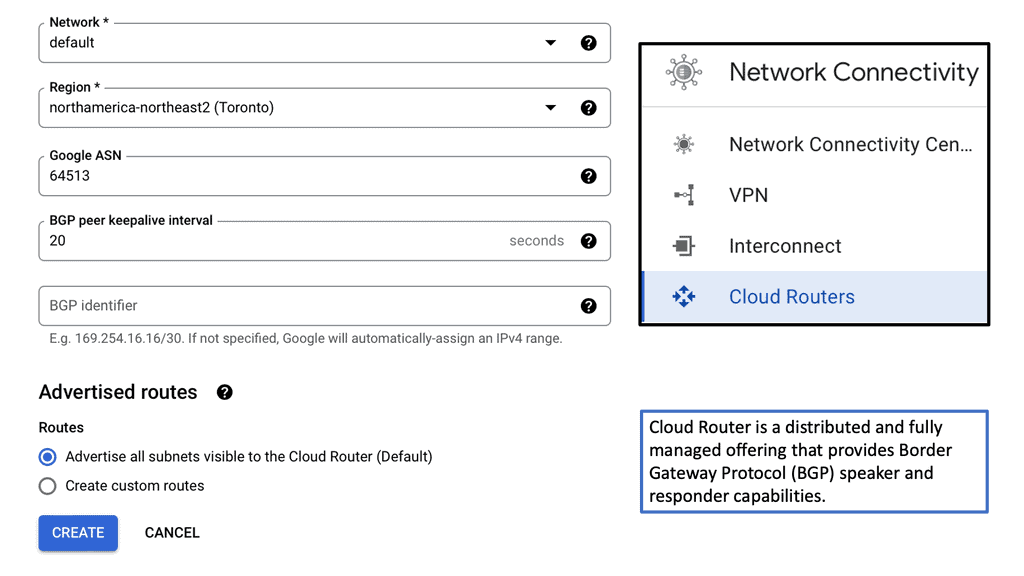
Network Connectivity Center (NCC)
At the heart of Network Connectivity Center is the formidable Google Cloud. With its vast global infrastructure and advanced technologies, Google Cloud enables NCC to offer unparalleled connectivity solutions. By leveraging Google’s extensive network, businesses can connect their on-premises environments, branch offices, and cloud resources effortlessly. The integration with Google Cloud ensures not only high performance but also robust security and compliance, making it a trusted choice for organizations worldwide.
### Key Features of Network Connectivity Center
Network Connectivity Center is packed with features designed to optimize your networking experience. One of its standout features is the centralized management console, which provides a unified view of your entire network. This makes it easier to monitor connectivity, troubleshoot issues, and implement changes across your network infrastructure. Additionally, NCC supports hybrid and multi-cloud environments, allowing businesses to connect and manage resources across different cloud providers seamlessly.

### Benefits for Businesses
Adopting Network Connectivity Center can yield numerous benefits for businesses. Firstly, it reduces complexity by centralizing network operations, which can lead to significant cost savings. Secondly, it improves network reliability and performance, ensuring that your applications and services run smoothly without interruptions. Furthermore, the enhanced security features of NCC help protect sensitive data, giving businesses peace of mind in an era where cyber threats are ever-present.
### How to Get Started
Getting started with Google’s Network Connectivity Center is straightforward. Businesses can begin by exploring Google’s comprehensive documentation and tutorials, which provide step-by-step guidance on setting up and configuring NCC. Additionally, Google offers support services to assist businesses in migrating their existing networks and optimizing their infrastructure for the cloud. With the right resources and support, transitioning to a more efficient network management system becomes a seamless process.
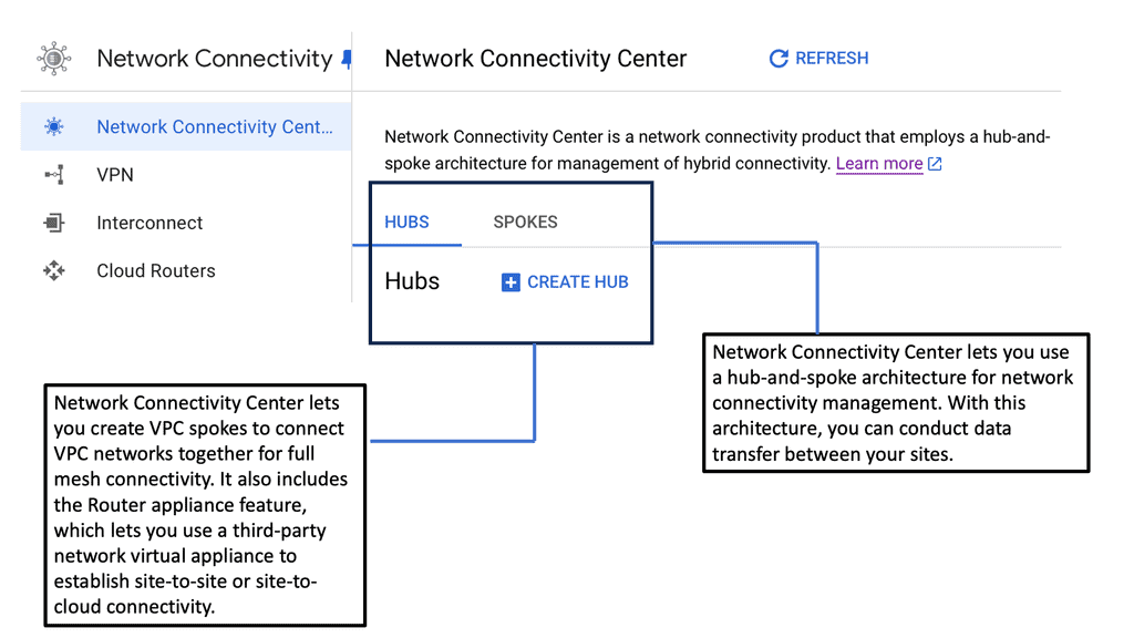
Network Connectivity Center: Hub and Spoke Model
In the hub-and-spoke model, the hub signifies a central or lead organization that serves as the coordinating entity. The spokes, on the other hand, represent partner organizations that are directly linked to the hub. Each spoke interacts directly with the hub but not necessarily with each other.


 **Improving Network Connectivity**
**Network Monitoring**
Network monitoring is the practice of observing and analyzing the performance and availability of computer networks. It involves tracking various network components, such as routers, switches, servers, and applications, to identify potential issues. Network monitoring allows for proactive problem identification, enabling IT teams to detect and resolve issues before they escalate. This prevents costly downtime and minimizes the impact on business operations.
**Understanding Network Scanning**
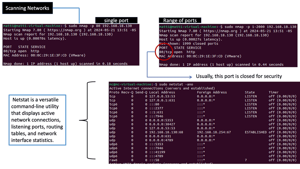
Network scanning is the systematic process of identifying, mapping, and analyzing network devices, services, and vulnerabilities. By conducting network scans, organizations gain valuable insights into their network infrastructure, identifying potential weak points and areas for improvement.
Several techniques are employed for network scanning, each with strengths and applications. Some common methods include port scanning, vulnerability scanning, and network mapping. Port scanning involves probing network ports to determine which ones are open and potentially vulnerable. Vulnerability scanning focuses on detecting and assessing vulnerabilities within the network infrastructure. Network mapping aims to create a comprehensive map of devices and their connections within the network.
**Identifying and Mapping Networks**
To troubleshoot the network effectively, you can use a range of tools. Some are built into the operating system, while others must be downloaded and run. Depending on your experience, you may choose a top-down or a bottom-up approach.
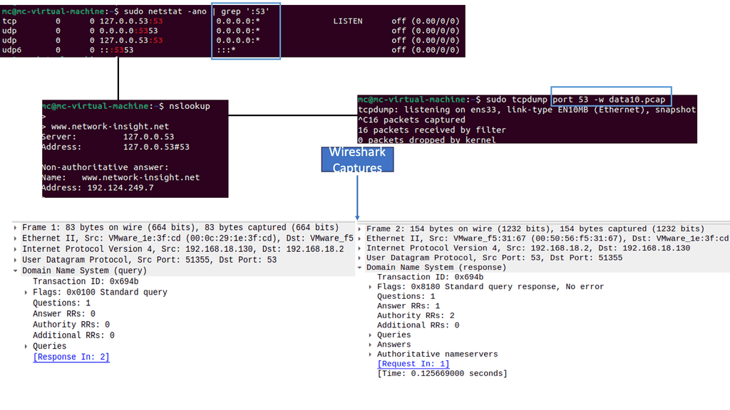
Wireshark, also known as Ethereal, is a free and open-source packet analyzer that allows you to capture, analyze, and interpret network traffic. It supports various operating systems and provides an intuitive graphical user interface (GUI) for ease of use. With Wireshark, you can scrutinize network protocols, identify anomalies, troubleshoot network issues, and enhance security.
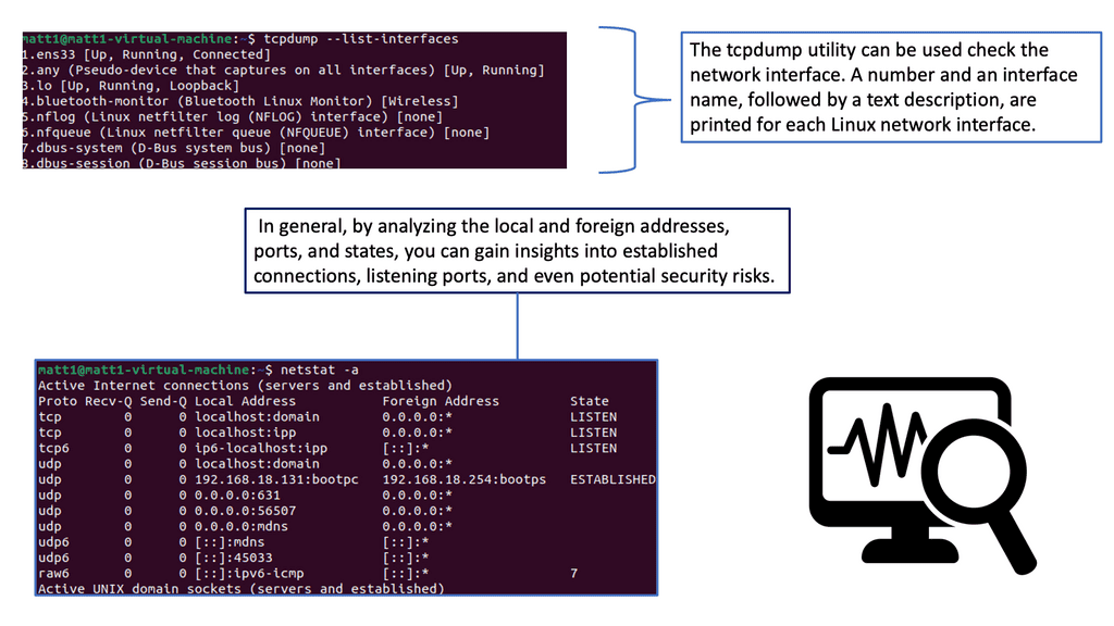
Tcpdump is a command-line packet analyzer tool for capturing and analyzing network traffic. It provides information about packets traversing your network, including source and destination addresses, protocols used, and packet payloads. With tcpdump, you can gain valuable insights into network behavior, diagnose network issues, and uncover potential security threats.
 Container Network Connectivity
The Basics of Docker Network Connectivity
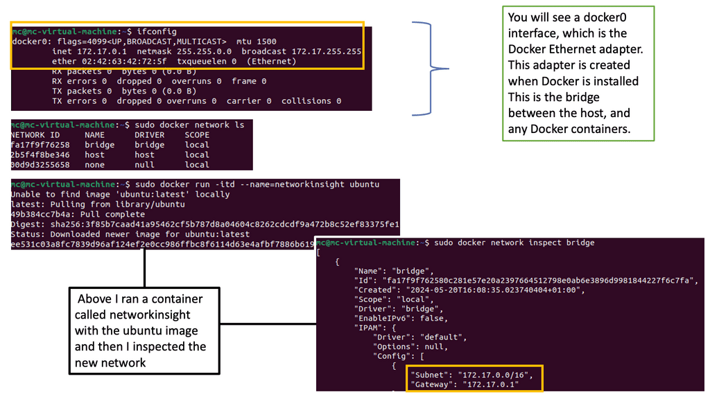
Before diving into advanced networking concepts, let’s start with the basics. Docker provides a default bridge network that allows containers on the same host to communicate. This bridge network assigns IP addresses to containers and provides a simple way for them to interact. However, other networking options, such as host and overlay networks, are available.
Docker Default Networking
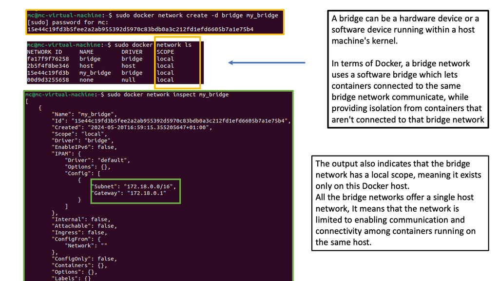
Docker default networking, also known as the bridge network, is the default networking mode when you create a new Docker container. This mode enables containers to communicate with each other using IP addresses within the same bridge network. By default, Docker creates a ” bridge ” network on the host machine.
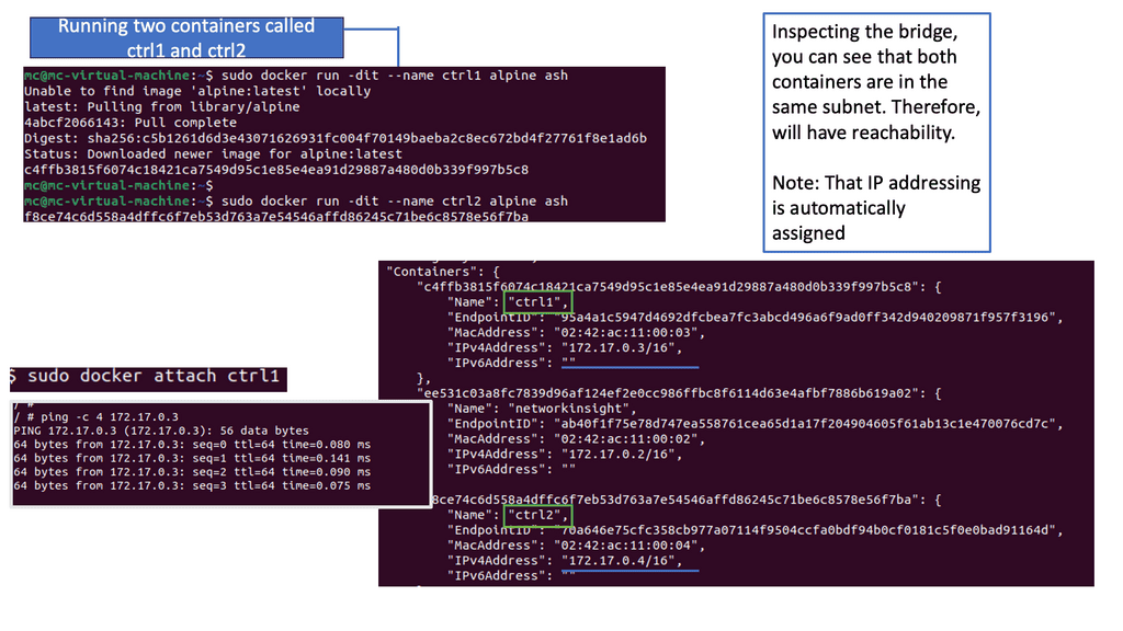
One critical advantage of Docker default networking is its simplicity and ease of use. Containers within the same bridge network can communicate with each other using their container names as hostnames, making it straightforward to establish connections. Additionally, Docker default networking provides automatic DNS resolution for container names, simplifying the process of addressing containers within the network.
Exploring Docker Default Networking Configuration
Understanding Docker’s configuration options is essential to grasp its default networking fully. Docker allows you to customize the bridge network by modifying bridge options, such as IP address ranges, subnet masks, and gateway settings. This flexibility enables you to tailor the networking environment to suit your requirements.
While Docker default networking offers many benefits, knowing potential challenges and limitations is essential. One limitation is that containers within different bridge networks cannot communicate directly with each other. To establish communication between containers in separate bridge networks, you may need to configure additional networking solutions, such as Docker overlay networks or custom network bridges.
 Docker Orchestration: What is Docker Swarm?
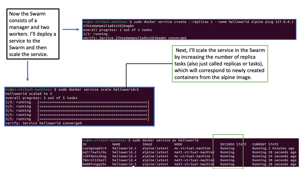
Docker Swarm is a native clustering and orchestration solution provided by Docker. It allows you to create and manage a swarm of Docker nodes, turning them into a single virtual Docker host. This means you can deploy and scale your applications across multiple machines, distributing the workload efficiently.
To effectively use Docker Swarm, it’s essential to grasp its key concepts and architecture. At the heart of Docker Swarm lies the swarm manager, which acts as the control plane for the entire swarm. It handles tasks such as service discovery, load balancing, and scheduling. On the other hand, Worker nodes are responsible for running the actual containers.
Deploying Services with Docker Swarm
One of Docker Swarm’s main benefits is its seamless deployment of services. With a simple command, you can define your services’ desired state, including the number of replicas, resource constraints, and network configurations. Docker Swarm distributes the tasks across the available nodes and ensures high availability.
Scalability and load balancing are crucial in a production environment. Docker Swarm makes scaling your services horizontally by adding or removing replicas easy. It also provides built-in load-balancing mechanisms that distribute incoming traffic evenly across the containers, ensuring optimal performance.
Docker Swarm offers robust mechanisms for high availability and fault tolerance. Replicating services across multiple nodes ensures that even if a node fails, the containers will be rescheduled on other available nodes. This provides resilience and minimizes service downtime.

Network Connectivity for Virtual Switching
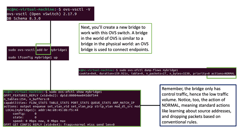
Understanding Open vSwitch
Open vSwitch, often called OVS, is an open-source software switch designed to enable network virtualization. It operates at the data link layer of the networking stack, providing a flexible and scalable solution for virtualized environments. Its robust features make Open vSwitch a go-to option for implementing virtual switches in small-scale and large-scale deployments.
Open vSwitch offers a wide range of features that contribute to its versatility. From standard switch functionality to advanced capabilities like support for tunneling protocols, Open vSwitch has it. It provides flexible port configurations and VLAN support and even implements the OpenFlow protocol for enhanced control and management. With its modular architecture and support for multiple virtualization platforms, Open vSwitch is ideal for network administrators seeking a reliable and scalable solution.
Use Cases of Open vSwitch:
Open vSwitch finds applications in various networking scenarios. It can be used in virtualized data centers to create and manage virtual networks, enabling efficient resource utilization and dynamic network provisioning. Open vSwitch is also commonly utilized in software-defined networking (SDN) environments, which bridges physical and virtual networks. Additionally, Open vSwitch can be integrated with orchestration frameworks like OpenStack to provide seamless network connectivity for virtual machines.
Testing Network Connectivity
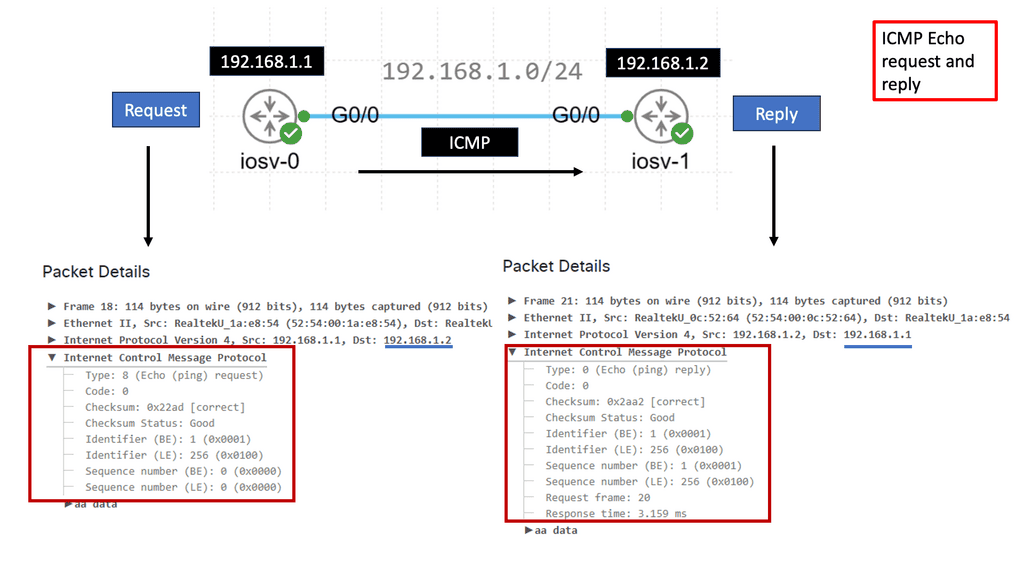
What is ICMP?
ICMP, or Internet Control Message Protocol, is integral to the TCP/IP suite. It operates at the network layer and facilitates communication between network devices. Network devices generate and send ICMP messages to convey information about network errors, troubleshooting, and other important notifications.
ICMP serves various functions contributing to a network’s proper functioning and maintenance. Some of its essential functions include:
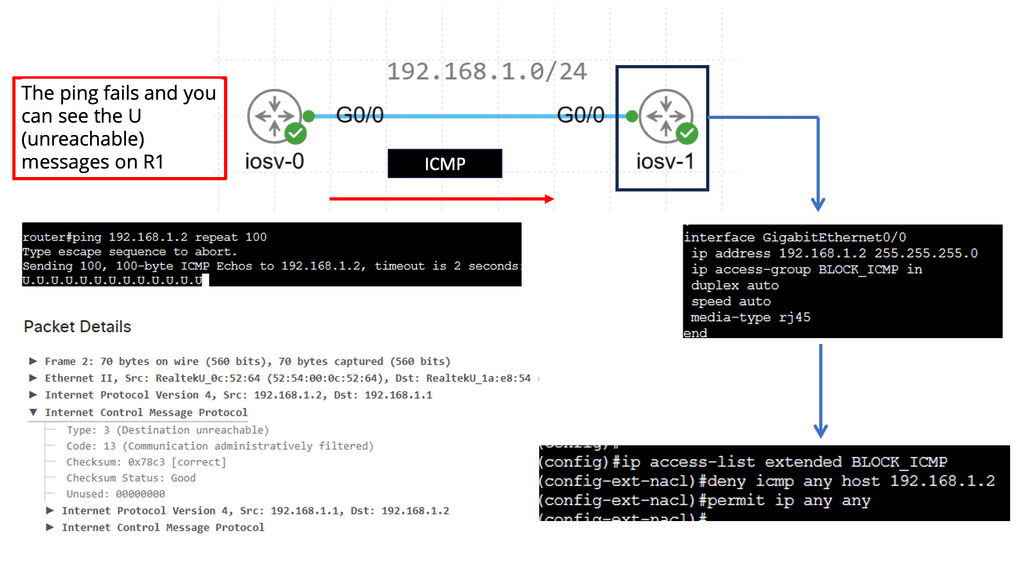
1. Error Reporting: ICMP allows network devices to report errors encountered while transmitting IP packets. These errors can range from unreachable hosts to time exceeded during packet fragmentation.
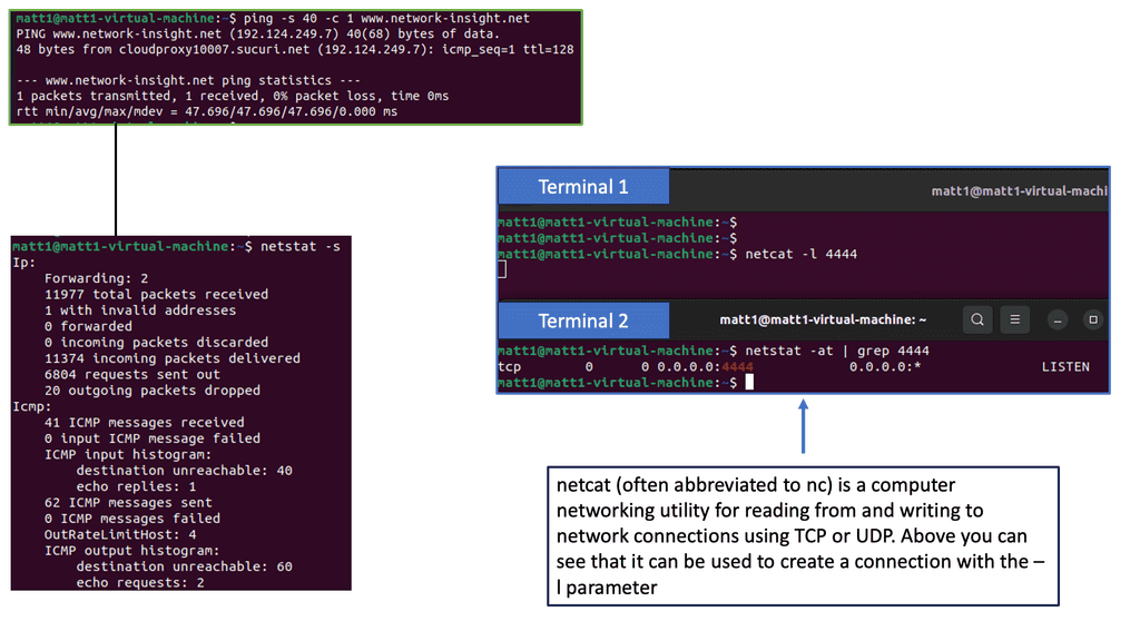
2. Network Troubleshooting: ICMP provides essential tools for network troubleshooting, such as the famous “ping” command. By sending ICMP Echo Request messages, devices can check a destination host’s reachability and round-trip time.
3. Path MTU Discovery: ICMP assists in determining the Maximum Transmission Unit (MTU) of a path between two hosts. This allows for efficient packet transmission without fragmentation.
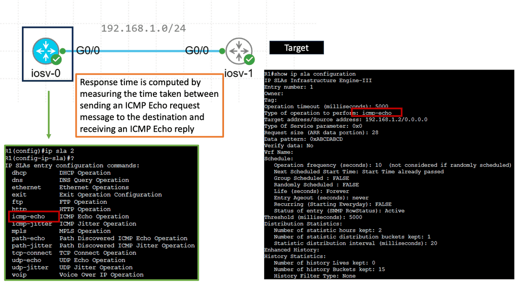
Understanding IP SLAs ICMP Echo Operations
IP SLAs, for Internet Protocol Service Level Agreements, is a Cisco feature that enables network administrators to measure network performance, verify service guarantees, and proactively monitor network devices. ICMP Echo Operations, or ping, is a widely used and crucial component within IP SLAs. ICMP Echo Operations sends Internet Control Message Protocol (ICMP) echo requests to measure network connectivity and response times.
IP SLAs ICMP Echo Operations offer several benefits for network administrators. First, they allow them to proactively monitor network connectivity and detect potential issues before they impact end-users. Administrators can ensure that network devices are reachable and respond within acceptable time frames by periodically sending ICMP echo requests.
Additionally, IP SLAs ICMP Echo Operations provide valuable data for troubleshooting network performance problems, allowing administrators to pinpoint bottlenecks and latency issues.
Restricting Network Connectivity
IPv6 Standard ACL
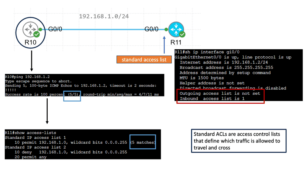
Standard access lists are one of the two types of access lists in Cisco IOS, the other being extended access lists. Standard access lists evaluate only packets’ source IP addresses, unlike extended access lists. They are commonly used for basic filtering and can be powerful tools in network security.
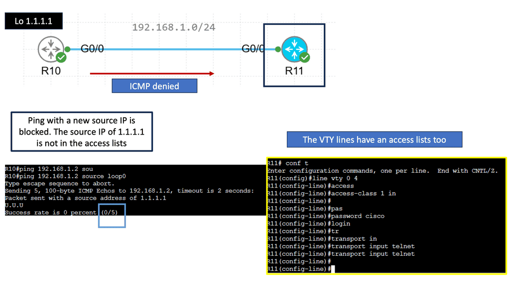
Standard access lists find various applications in network configurations. One everyday use case is restricting access to network resources based on the source IP address. For example, an administrator can create a standard access list to allow or deny specific IP addresses from accessing a particular server or network segment. Standard access lists can also filter traffic for network management purposes, such as limiting Telnet or SSH access to specific hosts.
Example: IPv6 Access Lists
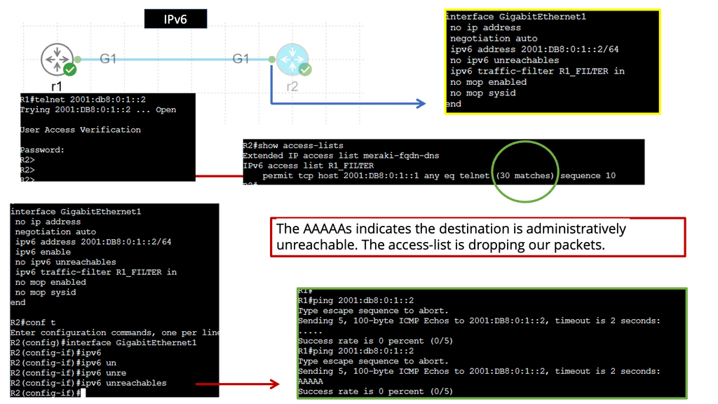
Understanding IPv6 Access-lists
IPv6 access lists serve as a set of rules or filters that control traffic flow in a network. They allow administrators to permit or deny specific types of traffic based on various criteria, such as source and destination IP addresses, ports, and protocols. Unlike their IPv4 counterparts, IPv6 access lists are designed to handle the unique characteristics of IPv6 addresses, ensuring compatibility and efficient network management.
Implementing IPv6 access lists brings many benefits to network security. First, they enable administrators to control network traffic precisely, allowing only authorized connections and blocking potential threats. Second, IPv6 access lists facilitate network segmentation, allowing administrators to create separate security zones and enforce stricter policies. Additionally, these access lists provide the flexibility to prioritize specific types of traffic, ensuring optimal network performance.
Network Connectivity & Enterprise Routing Protocols
**IPv4 and IPv6 Routing Protocols**
Routing protocols for IPv4 networks play a crucial role in determining the path data packets take as they traverse the internet. One of the most widely used protocols is the Routing Information Protocol (RIP), which uses hop count as a metric to determine the best route. Another popular protocol is the Open Shortest Path First (OSPF), known for its scalability and fast convergence. Additionally, the Border Gateway Protocol (BGP) is essential for routing between autonomous systems, making it a vital component of the global internet.
With the depletion of IPv4 addresses, IPv6 has emerged as the next generation of IP addressing. IPv6 routing protocols have been developed to accommodate the larger address space and improve the features of this new protocol. One of the prominent routing protocols for IPv6 is OSPFv3, an extension of OSPF for IPv4. It allows for the routing of IPv6 packets and provides efficient intra-domain routing in IPv6 networks. Another protocol, the Enhanced Interior Gateway Routing Protocol for IPv6 (EIGRPv6), offers advanced capabilities such as route summarization and load balancing.
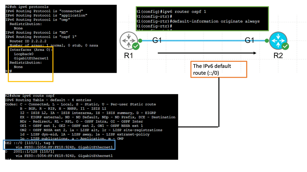
**Example: OSPFvs IPv6 Routing**
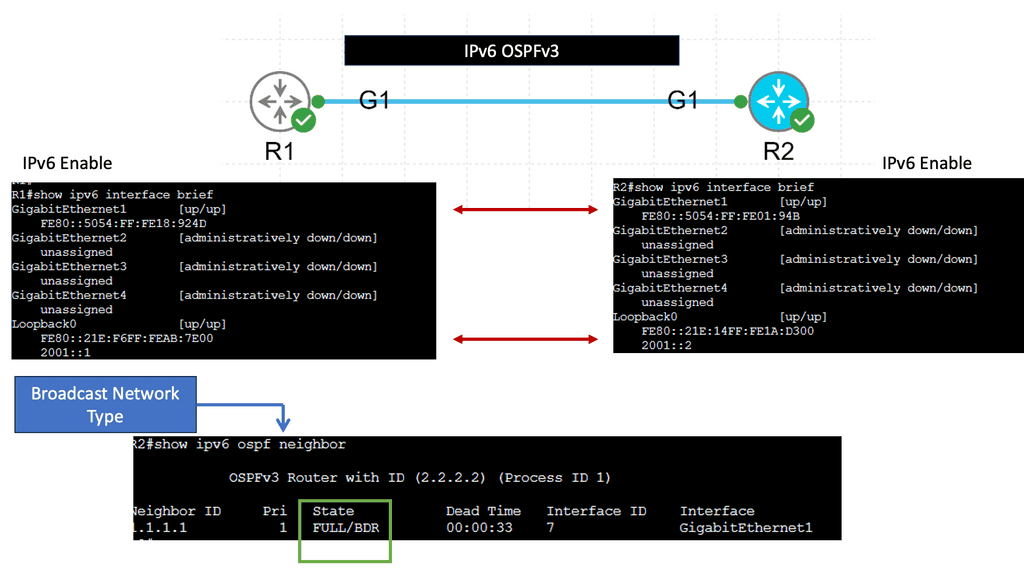
IPv6 OSPFv3, which stands for Open Shortest Path First version 3, is a routing protocol designed explicitly for IPv6 networks. It is an enhanced version of OSPFv2, the routing protocol used for IPv4 networks. OSPFv3 operates at the network layer and determines the most efficient paths for data packets to travel in an IPv6 network.
One of the significant benefits of IPv6 OSPFv3 is its scalability. As organizations expand their networks and connect more devices, scalability becomes critical. IPv6 OSPFv3 is designed to handle large networks efficiently, ensuring optimal routing performance even in complex environments.
Another advantage of IPv6 OSPFv3 is its support for multiple IPv6 address families. It can handle IPv6 addresses and provide routing capabilities for various network services. This flexibility allows for seamless integration of different network protocols and services within an IPv6 infrastructure.
**Network Address Translation (NAT)**
NAT, or Network Address Translation, is a technique for modifying network address information in IP packet headers while in transit across a routing device. Its primary purpose is to enable sharing of limited IP addresses among multiple devices within a private network. NAT acts as a mediator, providing a layer of security and managing the distribution of public IP addresses.
NAT is a technique employed by routers to allow multiple devices within a private network to share a single public IPv4 address. Through NAT, private IP addresses are translated into a single public IP address, enabling internet connectivity for all devices within the network.
There are various types of NAT, including Static NAT, Dynamic NAT, and Port Address Translation (PAT). Each type serves a specific purpose, whether it’s mapping a single private IP to a single public IP or allowing multiple private IPs to share a single public IP.
Scarcity of IPv4 Addresses: As mentioned earlier, the limited pool of available IPv4 addresses has led to the adoption of NAT to conserve address space. However, NAT introduces its challenges, including limitations in peer-to-peer applications, complex configurations, and potential performance bottlenecks.
**IPv6 and NAT**
Contrary to popular belief, NAT has a role in the IPv6 ecosystem. Although IPv6 provides a vast address space, the widespread use of NAT in IPv4 has led to a reliance on its functionalities. NAT in IPv6 operates differently, focusing more on protocol translation and maintaining compatibility with IPv4 networks.
Despite the abundant address space in IPv6, NAT still offers several benefits. First, it enhances network security by acting as a barrier between public and private networks, making it more difficult for malicious entities to exploit vulnerabilities. Additionally, NAT can aid network troubleshooting, allowing administrators to monitor and control traffic flow more effectively.
While NAT brings advantages, it also presents specific challenges and considerations. One notable concern is the potential impact on end-to-end communication and the introduction of additional processing overhead. Furthermore, the complex configurations and compatibility issues between IPv6 and NAT devices can pose challenges during implementation.
**IPv6 Transition Mechanisms**
IPv6 transition mechanisms enable coexistence and smooth migration from IPv4 to IPv6.
Dual Stack: One prominent transition mechanism is dual stack. With dual stack, devices are configured to simultaneously support IPv4 and IPv6 protocols. This allows for a seamless transition period during which both address families can coexist. Dual stack provides compatibility and flexibility, ensuring smooth communication between IPv4 and IPv6 networks.
Tunneling: Tunneling is another critical mechanism used during the IPv6 transition. It encapsulates IPv6 packets within IPv4 packets, allowing them to traverse IPv4-only networks. Tunneling provides a way to connect IPv6 islands over an IPv4 infrastructure. Different tunneling techniques, such as 6to4, Teredo, and ISATAP, offer varying approaches to encapsulating and transmitting IPv6 traffic over IPv4 networks.
Translation: IPv6 translation mechanisms bridge the gap between IPv4 and IPv6 networks by facilitating communication between devices using different protocols. Network Address Translation IPv6 (NAT64) and IPv6-to-IPv4 (IVI) translation enable data exchange between IPv6 and IPv4 networks. These translation techniques are crucial in ensuring interoperability during the transition phase.
Address Resolution: Address resolution mechanisms aid in seamlessly integrating IPv6 and IPv4 networks. Address Resolution Protocol for IPv6 (ARPv6) and Neighbor Discovery Protocol (NDP) assist in resolving IPv6 and IPv4 addresses to Ethernet MAC addresses. These protocols enable devices to discover and communicate with each other on both IPv6 and IPv4 networks.
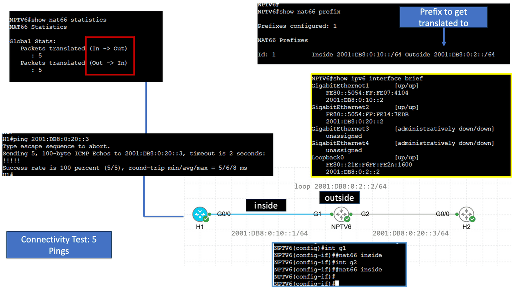
Example Technology: NPTv6 ( Network Address Translation )
Understanding NPTv6
NPTv6, also known as Network Prefix Translation for IPv6, is a stateless translation mechanism that facilitates the transition from IPv4 to IPv6. It allows for seamless communication between IPv6 and IPv4 networks by translating the IPv6 prefixes to IPv4 addresses. This enables organizations to adopt IPv6 while maintaining connectivity with existing IPv4 infrastructure.
One key advantage of NPTv6 is its ability to simplify the transition from IPv4 to IPv6. By providing a transparent translation mechanism, NPTv6 eliminates the need for complex dual-stack configurations or tunneling techniques. This dramatically reduces the operational overhead and facilitates a smoother migration to the next-generation IPv6 protocol.
Moreover, NPTv6 offers improved scalability and address management. With the depletion of IPv4 addresses, organizations are increasingly adopting IPv6. NPTv6 allows them to leverage their existing IPv4 infrastructure without needing address renumbering. This saves time and effort and ensures a more efficient utilization of available address space.
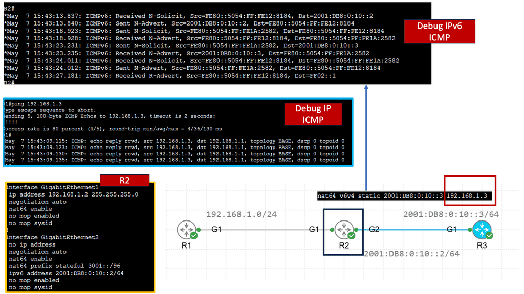
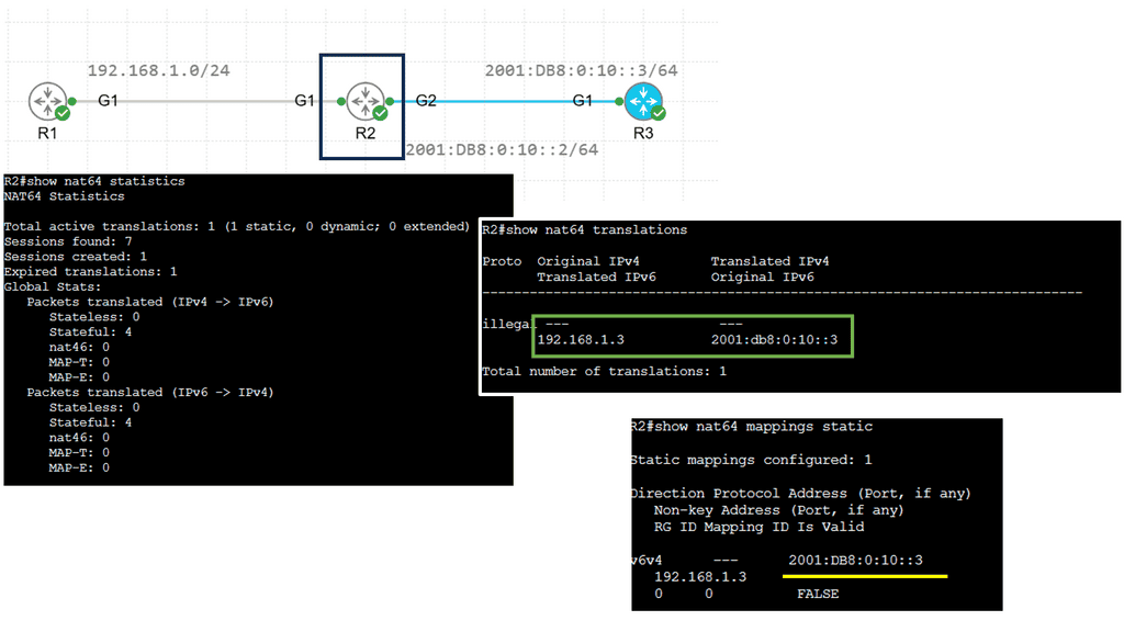
Example Technology: NAT64
Understanding NAT64
NAT64 bridges IPv6 and IPv4 networks, facilitating communication by translating IPv6 packets into IPv4 packets and vice versa. This allows devices using IPv6 to communicate with devices using IPv4, overcoming the incompatibility barrier. By utilizing NAT64, network operators can seamlessly transition from IPv4 to IPv6 without the need for dual-stack deployment.
One of NAT64’s key advantages is extending connectivity and reachability. With IPv4 exhaustion becoming a reality, NAT64 provides a solution to connect IPv6-only networks with the vast IPv4 Internet. This enables organizations to adopt IPv6 without losing connectivity to legacy IPv4 infrastructure. Additionally, NAT64 simplifies network management by reducing the complexity of maintaining dual-stack networks.
While NAT64 offers numerous benefits, being aware of its potential challenges is essential. One significant consideration is the impact on end-to-end communication. NAT64 introduces an additional layer of translation, which can affect specific applications and protocols that rely on direct IP communication. Network administrators must carefully evaluate the compatibility of their network infrastructure and applications before implementing NAT64.
Organizations have several strategies for successfully deploying NAT64. One approach is stateless NAT64, where the translation is performed on the fly without storing session-specific information. Another strategy is stateful NAT64, which maintains a translation state to enable advanced features such as inbound connection initiation. Each deployment strategy has its benefits and considerations depending on the network’s specific requirements.
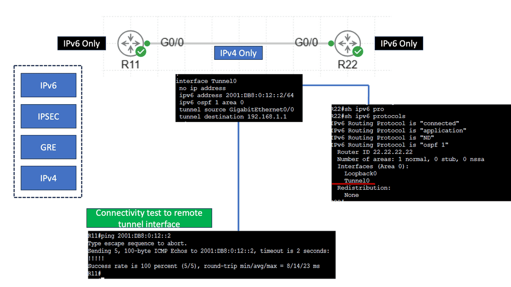
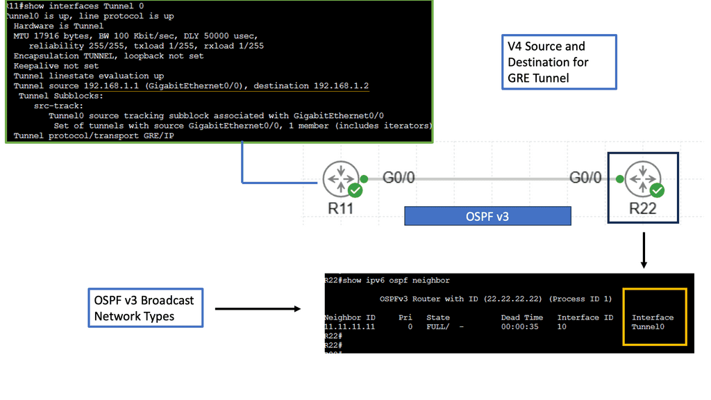
Example: IPv6 over IPv4 GRE
Understanding IPv6 over IPv4 GRE
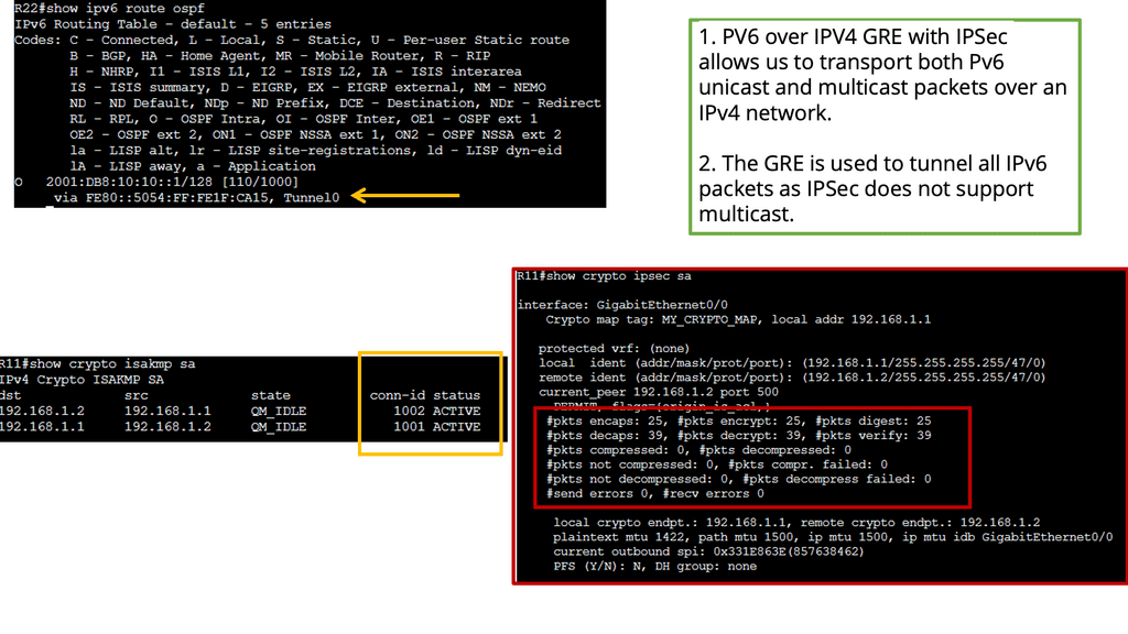
IPv6 over IPv4 GRE is a tunneling mechanism that encapsulates IPv6 packets within IPv4 packets. This enables communication between IPv6 networks over an IPv4 infrastructure. The Generic Routing Encapsulation (GRE) protocol provides the framework for encapsulating and decapsulating the packets, allowing them to traverse across different network domains.
Conversely, IPSec provides a secure framework for the encapsulated packets transmitted over the GRE tunnel. It offers authentication, integrity, and confidentiality services, ensuring the data remains protected from unauthorized access or tampering during transmission.
To establish an IPv6 over IPv4 GRE tunnel with IPSec, both ends of the tunnel must be properly configured. This includes configuring the tunnel interfaces, enabling GRE and IPSec protocols, defining the tunnel endpoints, and specifying the IPSec encryption and authentication algorithms.
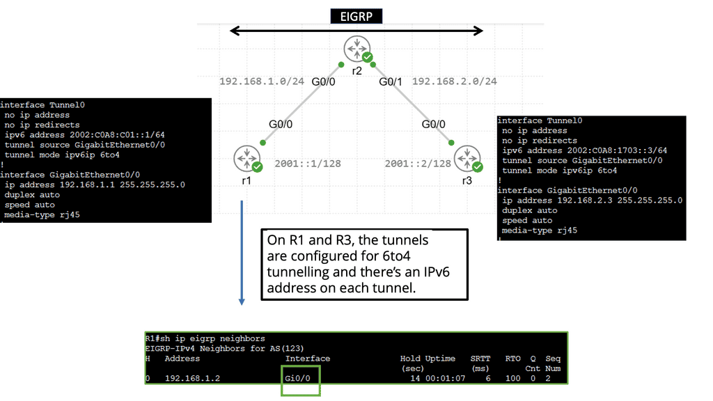
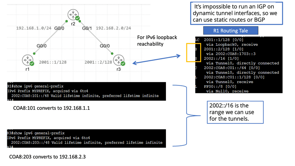
Example: IPv6 Automatic 6to4 Tunneling
Understanding IPv6 Automatic 6to4 Tunneling
IPv6 automatic 6to4 tunnelling is a technique that allows IPv6 packets to be transmitted over an IPv4 network. It enables communication between IPv6-enabled hosts over an IPv4 infrastructure. This method utilizes IPv6 addresses that are automatically assigned to facilitate tunneling.
Automatic 6to4 tunnelling utilizes a unique addressing scheme that enables communication between IPv6 hosts over an IPv4 network. It relies on encapsulating IPv6 packets within IPv4 packets, allowing them to traverse IPv4-only networks. This process involves using 6to4 relay routers that facilitate traffic exchange between IPv6 and IPv4 networks.
One key advantage of IPv6 automatic 6to4 tunneling is its ability to enable IPv6 connectivity without requiring extensive upgrades to existing IPv4 infrastructure. It provides a cost-effective and efficient solution for organizations transitioning to IPv6. Additionally, automatic 6to4 tunneling allows for the coexistence of IPv4 and IPv6 networks, ensuring seamless communication between both protocols.
Implementing IPv6 automatic 6to4 tunneling requires configuring 6to4 relay routers and ensuring proper routing between IPv4 and IPv6 networks. Network security must be considered, and the 6to4 relay routers must be protected from potential threats. Organizations must also monitor and manage their IPv6 addressing scheme to utilize available resources efficiently.
Related: Useful links to pre-information
Network Scanning
PowerShell and TNC
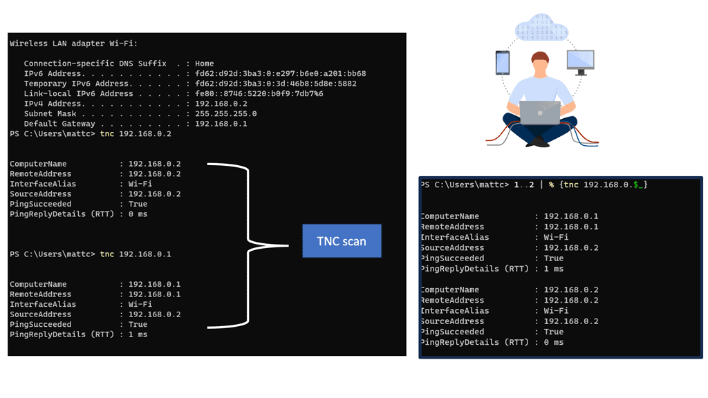
There are multiple ways to scan a network to determine host and open ports. PowerShell is used with variables and can perform advanced scripting. Below, I am using TNC to monitor my own Ubuntu VM and the WAN gateway.
Note:
The command stands for test network connection. This will display a summary of the request and a timeout. The PingSucceeded value will be equal to False. This output can indicate port filtering or that the target machine is powered off. The different statuses can vary between operating systems even when the results appear to be the same.
You can scan for the presence of multiple systems on the network with the following 1..2 | % {tnc 192.168.0.$_}
 Analysis:
- This command will attempt to scan 2 IP addresses in the range 192.168.0.1 and 192.168.0.2. The number range 1..1 can be extended, for example, 1..200, although it will take longer to complete.
- RDP is a prevalent protocol for administrative purposes on machines within a corporate network. This will display a summary of the request and show a successful connection. The output will show TcpTestSucceeded equals False. This indicates the system is not running and active, and a service could be running on port 3389, which is typically used for administration and remote desktop access.
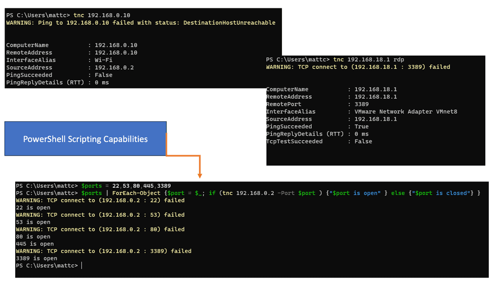
In the following example, we have a PowerShell code to create a variable called $ports by typing $ports = 22,53,80,445,3389 and pressing the Return key. This variable will store multiple standard ports found on the target system.
Then scan the machine using the new variable $ports with the command $ports | ForEach-Object {$port = $_; if (tnc 192.168.0.2 -Port $port ) {“$port is open” } else {“$port is closed”} }.
Analysis:
- This code will scan the IP address 172.31.24.20 and test each port number within the previously created $ports variable. For each port found, an open port message is displayed.
- If a port is not found, the message port is shown as closed. According to the output, several ports should be opened on the machine.
Connectivity with MAC address
Data link layer and MAC addresses
The following lab guide will explore the addresses of Media Access Control (MAC). MAC address works at the data link layer of the OSI model. This address may also be called the physical address since it’s the identifier assigned to a Network Interface Card (NIC).
While this is typically a physical card or controller that you might plug the ethernet or fiber into, MACs are also used to identify a pseudo-physical address for logical interfaces. This example shows the MAC changes seen in virtual machines or docker containers.
Note:
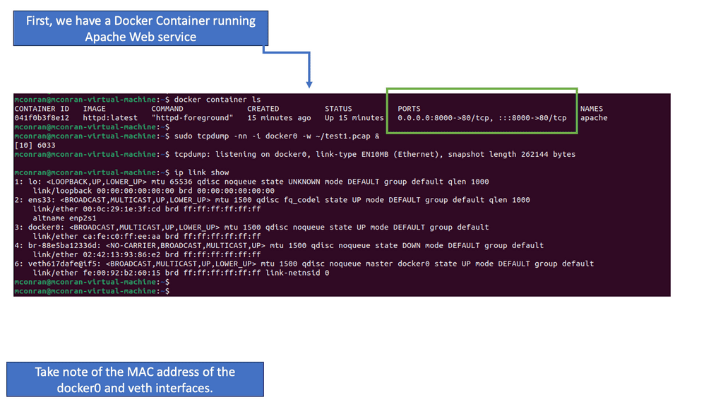
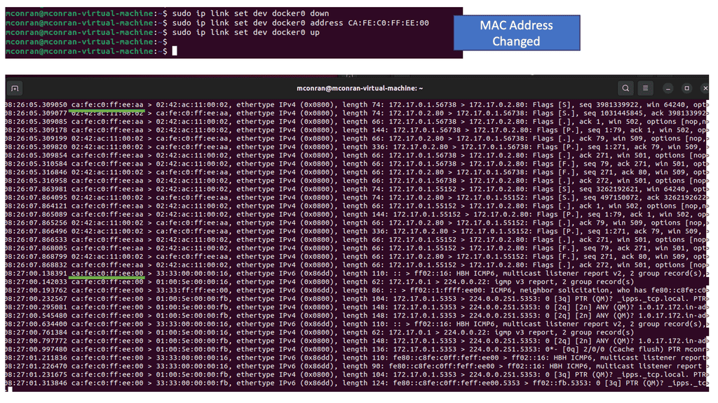
We have a Docker container running a web service and mapped port 80 on the container to 8000 on the Docker host, which is an Ubuntu VM. Also, notice the assigned MAC addresses; we will change these immediately. I’m also running a TCPDump to start a packet capture on Docker0.
Analysis:
- For this challenge, we will focus on the virtual network between your local endpoint and a web application running locally inside a docker container. The docker0 interface is your endpoint’s interface for communication with docker containers. The “veth…” interfaces are the virtual interfaces for web applications.
- Even though the MAC address is supposed to be a statically assigned identifier for the specific NIC, they are straightforward to change. We changed the MAC address in the following screenshots and dropped the Docker0.
Note:
Typically, attackers will spoof a MAC to mimic a desired type of device or use randomization software to mask their endpoint.
Now that you have seen how MAC addresses work, we can look at the ARP process.
Note:
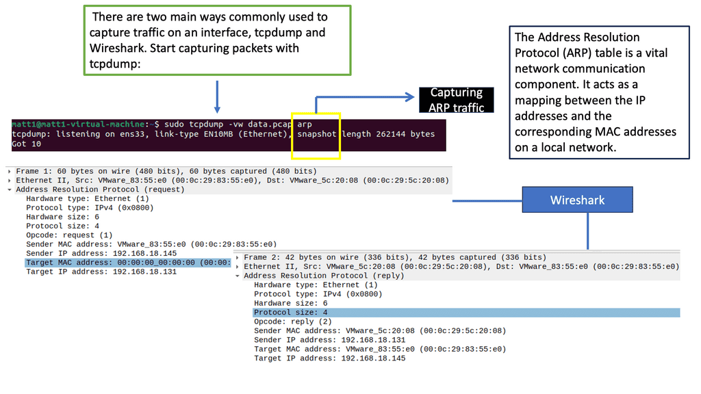
When endpoints communicate across networks, they use logical IP addresses to track where the requests come from and the intended destination. Once a packet arrives internal to an environment, networking devices must convert that IP address to the more specific “physical” location the packets are destined for. That “physical” location is the MAC address you analyzed in the last challenge. The Address Resolution Protocol (ARP) is the protocol that makes that translation.
 Analysis:
Let’s take this analysis step-by-step. When you send the curl request or any traffic, the first thing that must occur is to determine the intended destination. So we are giving the IP address as this, but we don’t know the Layer 2 MAC address. ARP is the process of finding this.
Where did the initial ARP request come from?
- It looks like the first packet has a destination MAC of “ff:ff:ff:ff:ff:ff.” Since your endpoint doesn’t know the destination MAC address, the first ARP packet is broadcast. Although this works, it is a bit of a security concern.
- A broadcast packet will be sent to every host within the local network. Unfortunately, the ARP protocol was not developed with security in mind, so in most configurations, the first host to respond to the ARP request will be the “winner.” This makes it very simple if an attacker controls a host within an environment to spoof their own MAC, respond faster, and effectively perform a Man-In-The-Middle (MITM) attack. Notice we have “Request how has ” above.
- The requesting IP address must be in the packet’s payload. This is an important distinction since most packets are returned to the requesting IP address found in the IPv4 header. This allows adversaries to use attacks such as ARP spoofing and MAC flooding since the original requester doesn’t have to be the intended destination. Notice we have a “Reply” at the end of the ARP process.
Understanding ARP:
ARP bridges the Network Layer (Layer 3) and the OSI model’s Data Link Layer (Layer 2). Its primary function is to map an IP address to a corresponding MAC address, allowing devices to exchange data efficiently.
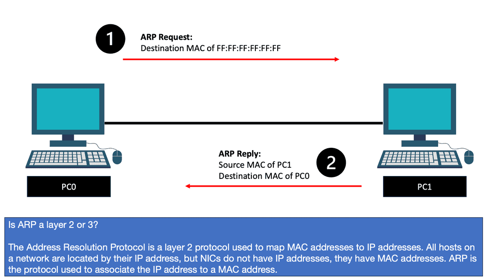
The ARP Process:
1. ARP Request: When a device wants to communicate with another on the same network, it sends an ARP request broadcast packet. This packet contains the target device’s IP address and the requesting device’s MAC address.
2. ARP Reply: Upon receiving the ARP request, the device with the matching IP address sends an ARP reply containing its MAC address. This reply is unicast to the requesting device.
3. ARP Cache: Devices store the ARP mappings in an ARP cache to optimize future communications. This cache contains IP-to-MAC address mappings, eliminating the need for ARP requests for frequently accessed devices.
4. Gratuitous ARP: In specific scenarios, a device may send a Gratuitous ARP packet to announce its presence or update its ARP cache. This packet contains the device’s IP and MAC address, allowing other devices to update their ARP caches accordingly.
**Host Enumeration**
Linux Host Enumeration
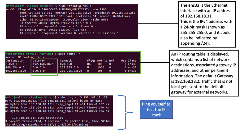
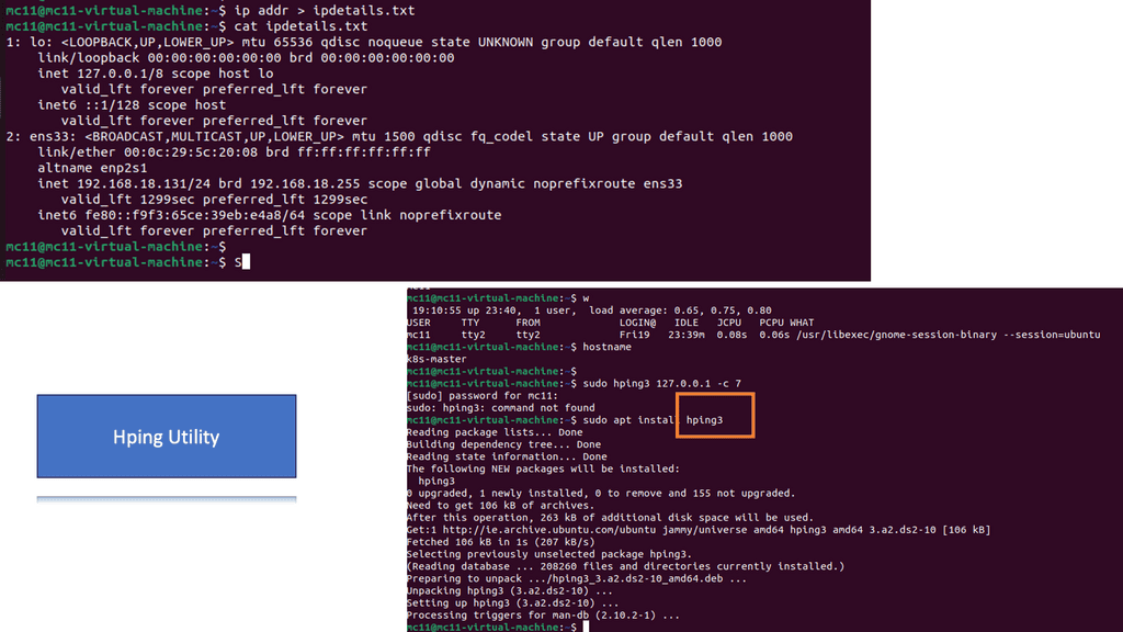
In a Linux environment, it is common practice to identify the host network details. A standalone isolated machine is scarce these days, and most systems are somehow interconnected to other systems. Run the following command to display IP information, saving the output to a text file instead of the popular method of displaying text on the screen.
Note:
1. Below, you can see there is usually a lot of helpful information displayed with network information. The screenshot shows that the network device ens33 and the MAC address are also listed.
2. Hping3 is a command-line tool for crafting and sending customized network packets. It offers various options and functionalities, making it invaluable for network discovery, port scanning, and firewall testing tasks.
3. One of hping3’s critical strengths lies in its advanced features. From TCP/IP stack fingerprinting to traceroute mode, hping3 goes beyond basic packet crafting and provides robust network analysis and troubleshooting techniques.
Analysis:
- The w command will show who, what, and where. In the above screenshot, a user is connecting from a remote location, which highlights how interconnected we are today; the connection could be anywhere in the world. Other helpful information here shows that the user has an open terminal bash and is running the w command.
- Use the hping command to ping your machine seven times using.
sudo hping3 127.0.0.1 -c 57. - The sudo is needed as elevated privileges are required to run hping3. The IP address 127.0.0.1 is the loopback address, meaning this is your machine. We work in a secure lab environment and cannot ping systems online.
- In the screenshot, errors will be displayed if there are any connection issues on the network. Generally, ping helps identify interconnected systems on the network. Hping is a much more advanced tool with many features beyond this challenge. It can also perform advanced techniques for testing firewall port scanning and help penetration testers look for weaknesses. It is a potent tool!
Network Connectivity & Network Security
So, we have just looked at generic connectivity. However, these networking and security devices will have two main functions. First, there is the network connectivity side of things.
So, we will have network devices that need to forward your traffic so it can reach its destination. Traffic is delivered based on IP. Keep in mind that IP is not guaranteed. Enabling reliable network connectivity is handled further up the stack. The primary version of IP used on the Internet today is Internet Protocol Version 4 (IPv4).
Due to size constraints with the total number of possible addresses in IPv4, a newer protocol was developed. The latest protocol is called IPv6. It makes many more addresses available and is increasing in adoption.
**Network Security and TCPdump**
Secondly, we will need to have network security devices. These devices allow traffic to pass through their interfaces if they deem it safe, and policy permits the traffic to pass through that zone in the network. The threat landscape is dynamic, and bad actors have many tools to disguise their intentions. Therefore, we have many different types of network security devices to consider.
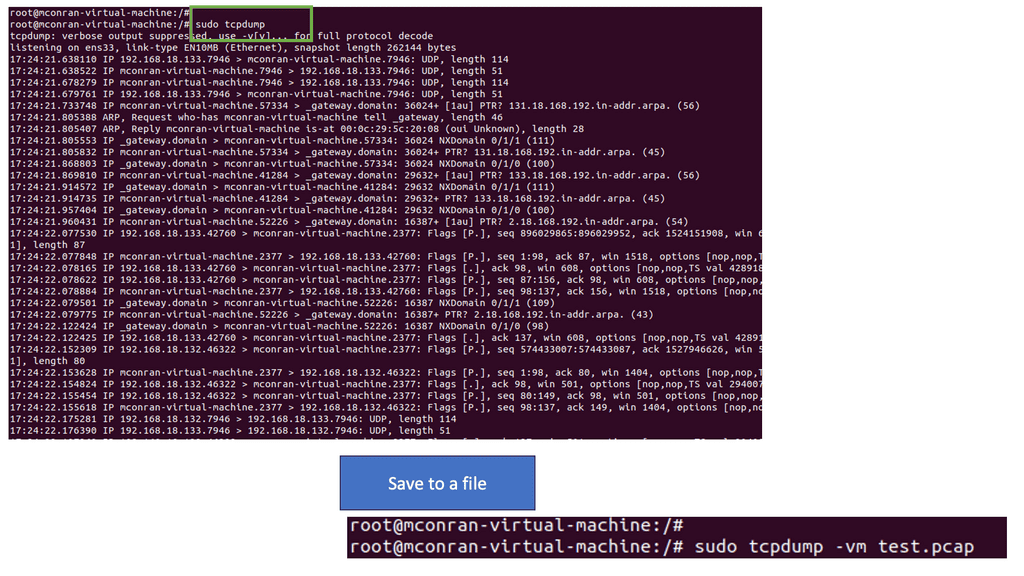
Tcpdump is a powerful command-line packet analyzer that allows users to capture and examine network traffic in real-time. It captures packets from a network interface and displays their content, offering a detailed glimpse into the intricacies of data transmission.
**Getting Started with TCPdump**
Understanding TCPdump’s primary usage and command syntax is crucial to its effective use. By employing a combination of command-line options, filters, and expressions, users can tailor their packet-capturing experience to suit their specific needs. We will explore various TCPdump commands and parameters, including filtering by source or destination IP, port numbers, or protocol types.
**Analyzing Captured Packets**
Once network packets are captured using TCPdump, the next step is to analyze them effectively. This section will explore techniques for examining packet headers and payload data and extracting relevant information. We will also explore how to interpret and decode different protocols, such as TCP, UDP, ICMP, and more, to understand network traffic behavior better.
**Capturing Traffic with TCPdump**
Note:
Remember that starting tcpdump requires elevated permissions and initiates a continuous traffic capture by default, resulting in an ongoing display of network packets scrolling across your screen. To save the output of tcpdump to a file, use the following command:
sudo tcpdump -vw test.pcap
Tip: Learn tcpdump arguments
sudoRun tcpdump with elevated permissions-vUser verbose output-wwrite output to the file
Analysis:
- Running TCPdump is an invaluable tool for network analysis and troubleshooting. It lets you capture and view the live traffic flowing through your network interfaces. This real-time insight can be crucial for identifying issues, understanding network behavior, and detecting security threats.
Next, to capture traffic from a specific IP address, at the terminal prompt, enter:
sudo tcpdump ip host 192.168.18.131
Tip: Learn tcpdump arguments
ipthe protocol to capturehost <ip address>limit the capture to a single host’s IP address
To capture a set number of packets, type the following command:
sudo tcpdump -c20
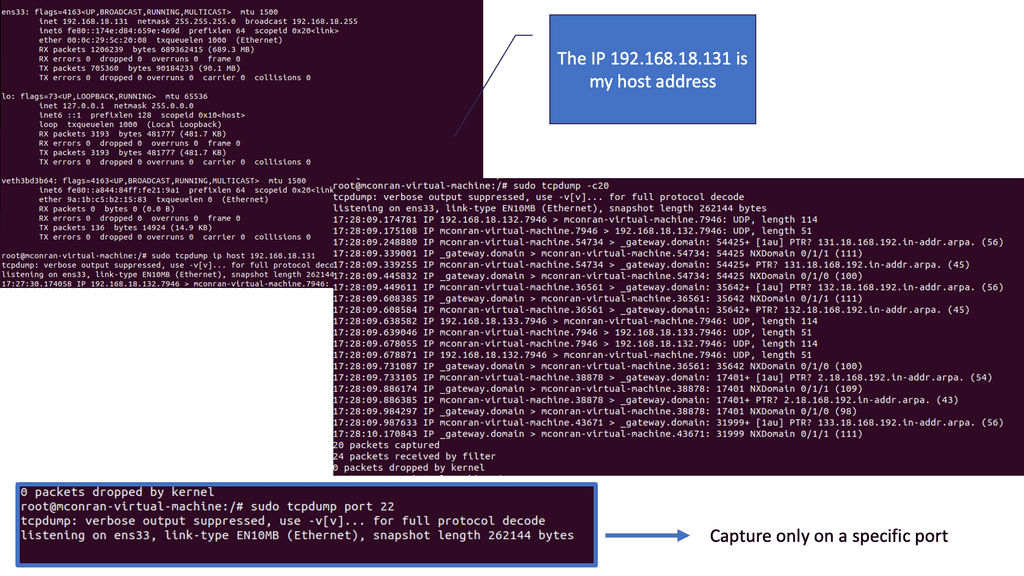
Analysis:
- Filtering tcpdump on a specific IP address streamlines the analysis by focusing only on the traffic involving that address. This targeted approach can reveal patterns, potential security threats, or performance issues related to that host.
- Limiting the packet count in a tcpdump capture, such as 20 packets, creates a more focused and manageable dataset for analysis. This can be particularly useful in isolating incidents or behaviors without being overwhelmed by continuous information.
- Tcpdump finds practical applications in various scenarios. Whether troubleshooting network connectivity issues, detecting network intrusions, or performing forensic analysis, tcpdump is an indispensable tool.
Networking Scanning with Python
Python and NMAP
I am scanning my local netowrk in this lab guide, looking for targets and potential weaknesses. Knowing my shortcomings will help strengthen the overall security posture. I am scanning and attempting to gain access to services with Python.
Network scanning involves identifying and mapping the devices and resources within a network. It helps identify potential vulnerabilities, misconfigurations, and security loopholes. Python, a versatile scripting language, provides several modules and libraries for network scanning tasks.
Note:
- Python offers various libraries and modules that can be used with Nmap for network scanning. One such library is “python-nmap,” which provides a Pythonic way to interact with Nmap. By leveraging this library, we can easily automate scanning tasks, customize scan parameters, and retrieve results for further analysis.
- The code will import the Nmap library used to provide Nmap functionality. Then, the most basic default scan will be performed against the Target 1 virtual machine.
Steps:
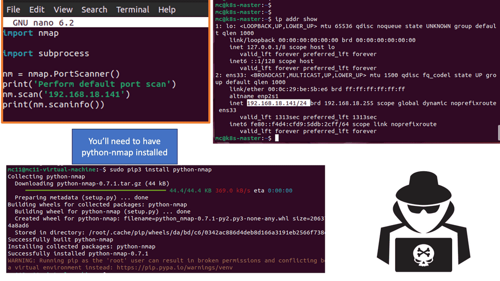
- Using the nano editor, create a new text file called scannetwork.py by typing nano scannetwork.py. This is where the Python script will be made.
- With nano open, enter the following Python code to perform a basic default port scan using Nmap with Python. Add your IP address for the Target 1 virtual machine to the script.
import nmap
import subprocess
nm = nmap.PortScanner()
print(‘Perform default port scan’)
nm.scan(‘add.ip.address.here’)
print(nm.scaninfo())
Note: The code will import the Nmap library to provide Nmap functionality, and then the most basic default scan will be performed against the Target 1 virtual machine.
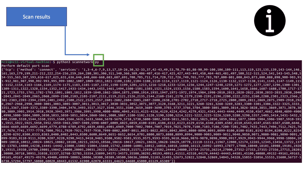 Analysis:
- Scan results may vary. The following output shows many numbers, signifying port numbers, with the scan completing quickly. With this type of full scan without arguments and the speed at which Python returns, the results will likely produce errors.
- Remember that you need to have NMAP installed first.

- Fortinet’s new FortiOS 7.4 enhances SASE - April 5, 2023
- Comcast SD-WAN Expansion to SMBs - April 4, 2023
- Cisco CloudLock - April 4, 2023