Network Components
Creating a computer network requires a lot of preparation and knowledge of the right components used. One of the first steps in computer networking is identifying what features to use and where to place them. This includes selecting the proper hardware, such as the Layer 3 routers, Layer 2 switches, and Layer 1 hubs if you are on an older network. Along with the right software, such as operating systems, applications, and network services. Or if any advanced computer networking techniques, such as virtualization and firewalling, are required.

Network Structure
Once the network components are identified, it’s time to plan the network’s structure. This involves deciding where each piece will be placed and how they will be connected. The majority of networks you will see today will be Ethernet-based. You will need a design process for more extensive networks. Still, for smaller networks, such as your home network, once physically connected, you are ready as all the network services are set up for you on the WAN router by the local service provider.
Network Design
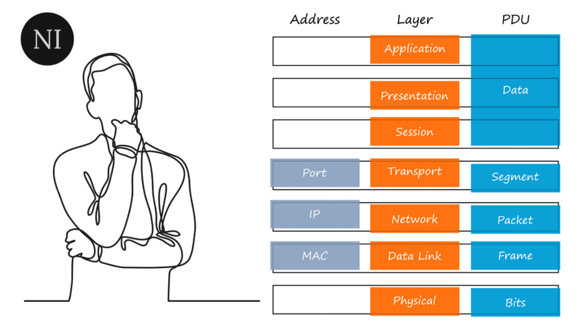
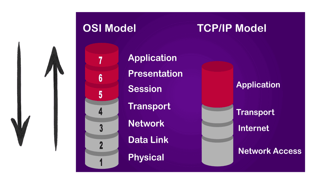
To embark on our journey into network design, it’s crucial to grasp the fundamental concepts. This section will cover topics such as network topologies, protocols, and the different layers of the OSI model. By establishing a solid foundation, you’ll be better equipped to make informed decisions in your network design endeavors.
Assessing Requirements and Goals
Before exploring the technical aspects of network design, it’s essential to identify your specific requirements and goals. This section will explore the importance of conducting a thorough needs analysis, considering factors such as scalability, security, and bandwidth. By aligning your network design with your objectives, you can build a robust and future-proof infrastructure.
Choosing the Right Equipment and Technologies
With a clear understanding of your requirements, it’s time to select the appropriate equipment and technologies for your network. We’ll delve into the world of routers, switches, firewalls, and wireless access points, discussing the criteria for evaluating different options. Additionally, we’ll explore emerging technologies like Software-Defined Networking (SDN) and Network Function Virtualization (NFV) that can revolutionize network design.
Designing for Efficiency and Redundancy
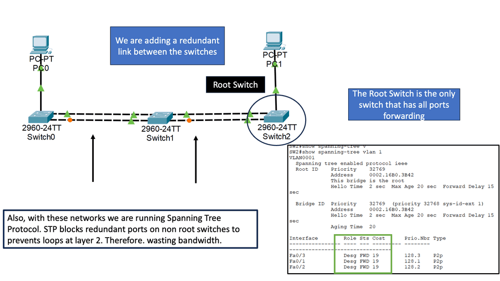
Efficiency and redundancy are vital aspects of network design that ensure reliable and optimized performance. This section will cover load balancing, fault tolerance, and network segmentation strategies. We’ll explore techniques like VLANs (Virtual Local Area Networks), link aggregation, and the implementation of redundant paths to minimize downtime and enhance network resilience.
Securing Your Network
Network security is paramount in an era of increasing cyber threats. This section will address best practices for securing your network, including firewalls, intrusion detection systems, and encryption protocols. We’ll also touch upon network access control mechanisms and the importance of regular updates and patches to safeguard against vulnerabilities.
Related: Additional links to internal content for pre-information:
- Data Center Topologies
- Distributed Firewalls
- Internet of Things Access Technologies
- LISP Protocol and VM Mobility.
- Port 179
- IP Forwarding
- Forwarding Routing Protocols
- Technology Insight for Microsegmentation
- Network Security Components
- Network Connectivity
Computer Networks |
|
Back to Basics: Computer Networks
A network is a collection of interconnected systems that share resources. Networks connect IoT (Internet of Things) devices, desktop computers, laptops, and mobile phones. A computer network will consist of standard devices such as APs, switches, and routers, the essential network components.
Network services
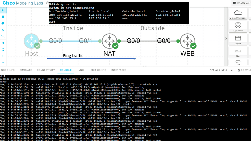
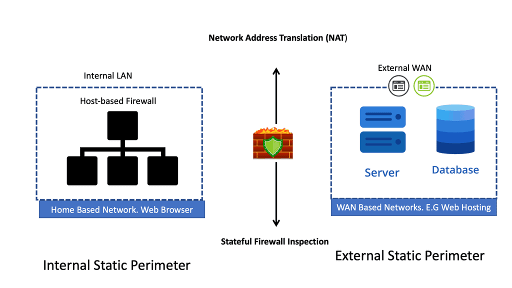
You can connect your network’s devices to other computer networks and the Internet, a global system of interconnected networks. So when we connect to the Internet, we secure the Local Area Network (LAN) to the Wide Area Network (WAN). As we move between computer networks, we must consider security.
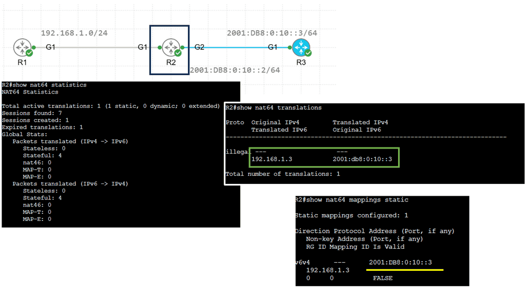
You will need a security device between these segments for a stateful inspection firewall. You are probably running IPv4, so you will need a network service called Network Address Translation (NAT). IPv6, the latest version of the IP protocol, does not need NAT but may need a translation service to communicate with IPv4-only networks.
♦Types of Networks
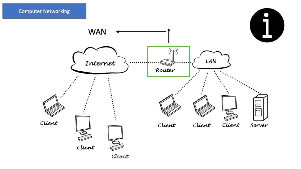
There are various types of computer networks, each serving different purposes. Local Area Networks (LANs) connect devices within a limited geographical area, such as homes or offices. Wide Area Networks (WANs) span larger areas, connecting multiple LANs. The internet itself can be considered the most extensive WAN, connecting countless networks across the globe.
Computer networking brings numerous benefits to individuals and businesses. It enables seamless communication, file sharing, and resource access among connected devices. In industry, networking enhances productivity and collaboration, allowing employees to work together efficiently regardless of physical location. Moreover, networking facilitates company growth and expansion by providing access to global markets.
Computer Networking |
|
Security and Challenges
With the ever-increasing reliance on computer networks, security becomes a critical concern. Protecting sensitive data, preventing unauthorized access, and mitigating potential threats are constant challenges. Network administrators employ various security measures such as firewalls, encryption, and intrusion detection systems to safeguard networks from malicious activities.
As technology continues to evolve, so does computer networking. Emerging trends such as cloud computing, the Internet of Things (IoT), and software-defined networking (SDN) are shaping the future of networking. The ability to connect more devices, handle massive amounts of data, and provide faster and more reliable connections opens up new possibilities for innovation and advancement.
Local Area Network
A Local Area Network (LAN) is a computer network that connects computers and other devices in a limited geographical area such as a home, school, office building, or closely positioned group of buildings. Ethernet cables typically connect LANs but may also be connected through wireless connections. LANs are usually used within a single organization or business but may connect multiple locations. The equipment in your LAN is in your control.
Wide Area Network
Then, we have the Wide Area Network (WAN). In contrast to the LAN, a WAN is a computer network covering a wide geographical area, typically connecting multiple locations. Your LAN may only consist of Ethernet and a few network services.
However, a WAN may consist of various communications equipment, protocols, and media that provide access to multiple sites and users. WANs usually use private leased lines, such as T-carrier lines, to connect geographically dispersed locations. The equipment in the WAN is out of your control.
LAN | WAN |
|
|
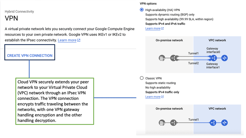
Virtual Private Network ( VPN )
We use a VPN to connect LAN networks over a WAN. A virtual private network (VPN) is a secure and private connection between two or more devices over a public network such as the Internet. Its purpose is to provide fast, encrypted communication over an untrusted network.
VPNs are commonly used by businesses and individuals to protect sensitive data from prying eyes. One of the primary benefits of using a VPN is that it can protect your online privacy by masking your IP address and encrypting your internet traffic. This means that your online activities are hidden from your internet service provider (ISP), hackers, and other third parties who may be trying to eavesdrop on your internet connection.
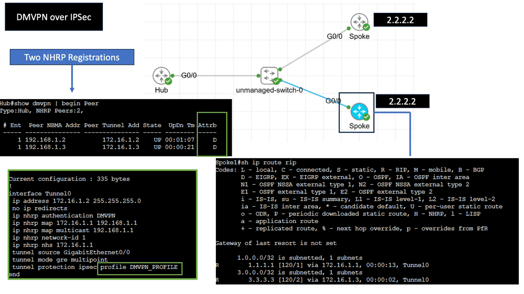
Example: VPN Technology
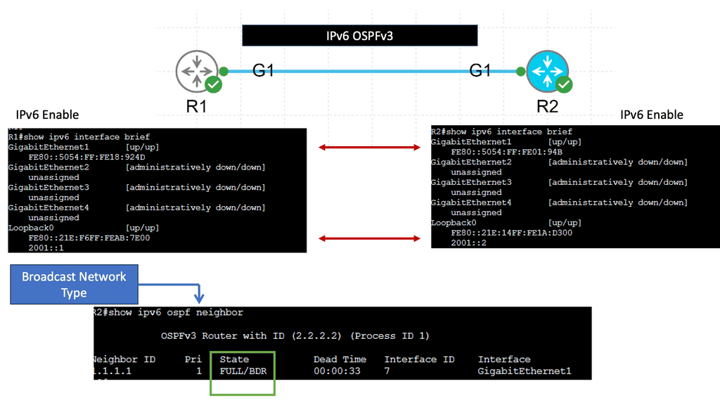
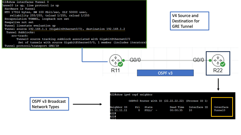
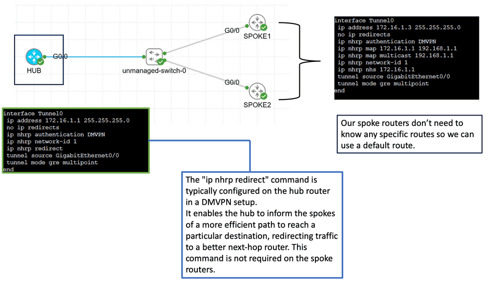
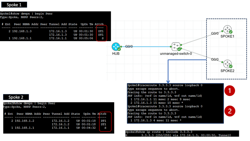
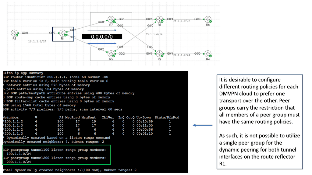
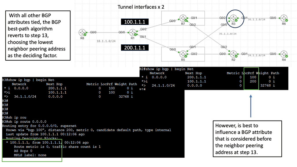
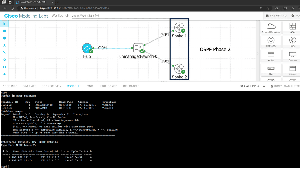
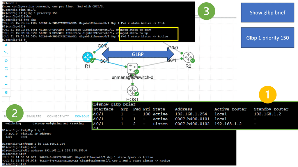
An example of a VPN technology is Cisco DMVPN. DMVPN operates in phases; there is DMVPN Pashe 1 to 3. For true hub and spoke, you would implement Phase 1; however, today, Phase 3 is the most popular, offering spoke-to-spoke tunnels. The screenshot below is an example of DMVPN Phase 1 running an OSPF network type of broadcast.
Computer Networking
Once the network’s components and structure have been determined, the next step is configuring computer networking. This involves setting up network parameters, such as IP addresses and subnets, and configuring routing tables.
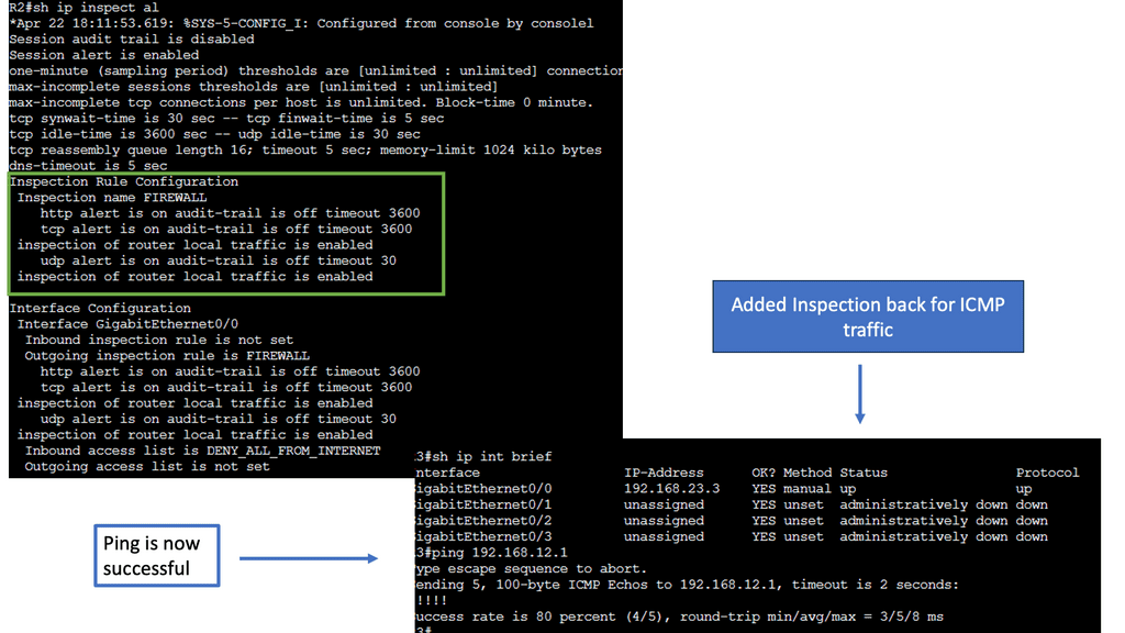
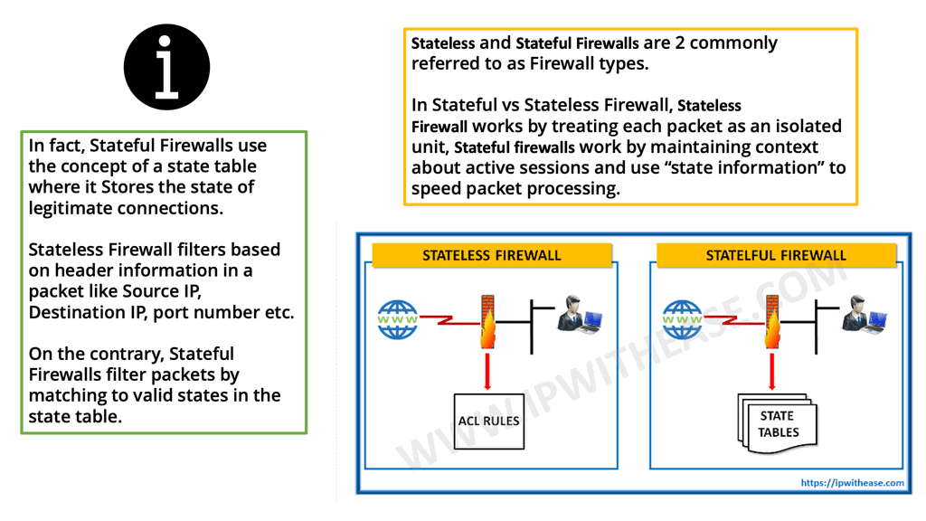
Remember that security is paramount, especially when connecting to the Internet, an untrusted network with a lot of malicious activity. Firewalls help you create boundaries and secure zones for your networks. Different firewall types exist for the other network parts, making a layered approach to security.
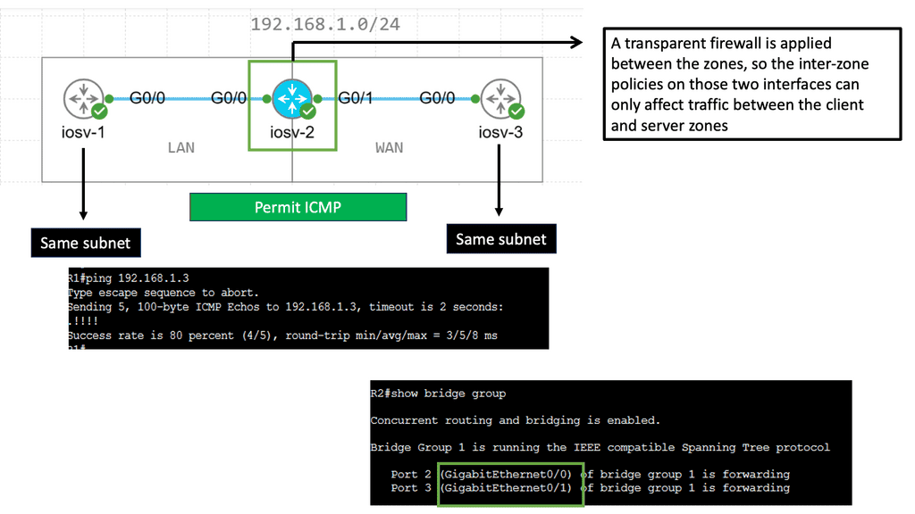
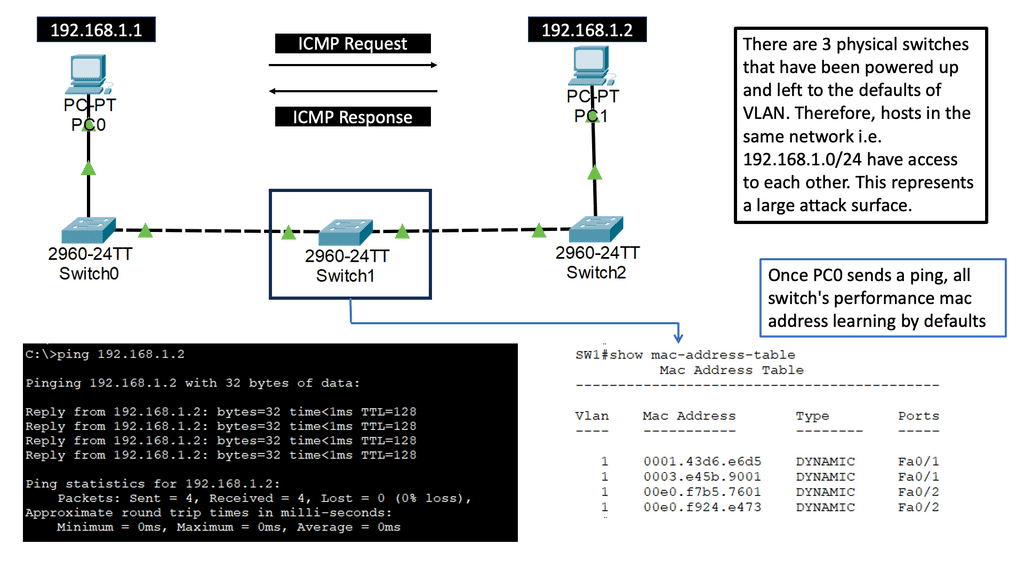
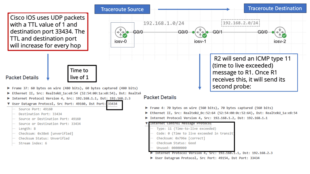
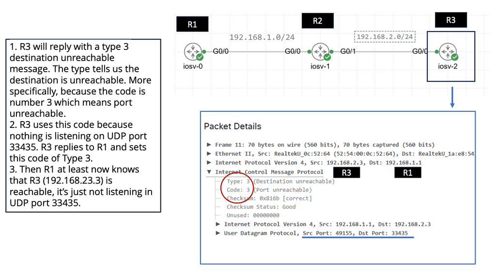
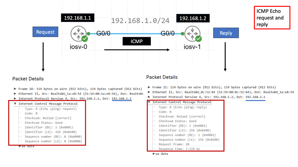
Once the computer networking is completed, the next step is to test the network. This can be done using tools such as network analyzers, which can detect any errors or issues present. You can conduct manual tests using Internet Control Message Protocol (ICMP) protocols, such as ping and traceroute. Testing for performance is only half of the pictures. It’s also imperative to regularly monitor the network for potential security vulnerabilities. So, you must have antivirus software, a computer firewall, and other endpoint security controls.
Finally, it’s critical to keep the network updated. This includes updating the operating system and applications and patching any security vulnerabilities as soon as possible. It’s also crucial to watch for upcoming or emerging technologies that may benefit the network.
Lab Guide: Endpoint Networking and Security
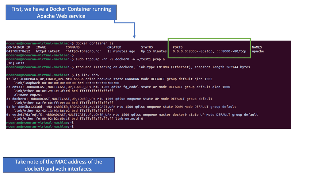
Address Resolution Protocol (ARP)
The first command you will want to become familiar with is arp.
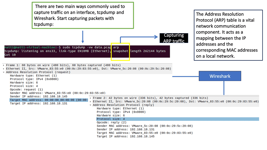
At its core, ARP is a protocol that maps an IP address to a corresponding MAC address. It enables devices within a local network to communicate with each other by resolving the destination MAC address for a given IP address. Devices store these mappings in an ARP table for efficient and quick communication.
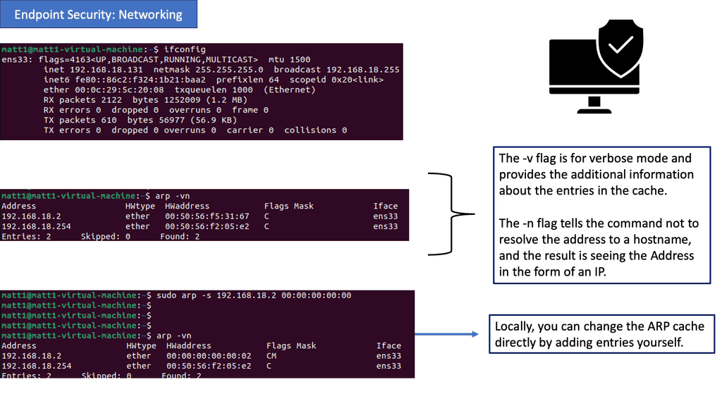
Analysis: What you see are 5 column headers explained as follows:
Address: The IP address of a device on the network identified through the ARP protocol is resolved to the hostname.
HWtype: This describes the type of hardware facilitating the network connection. In this case, it is an ethernet rather than a Wi-Fi interface.
HW address: The MAC address assigned to the hardware interface responding to ARP requests.
Flags Mask: A hex value translated into ASCII defines how the interface was set.
Iface: Lists the interface’s name associated with the hardware and IP address.
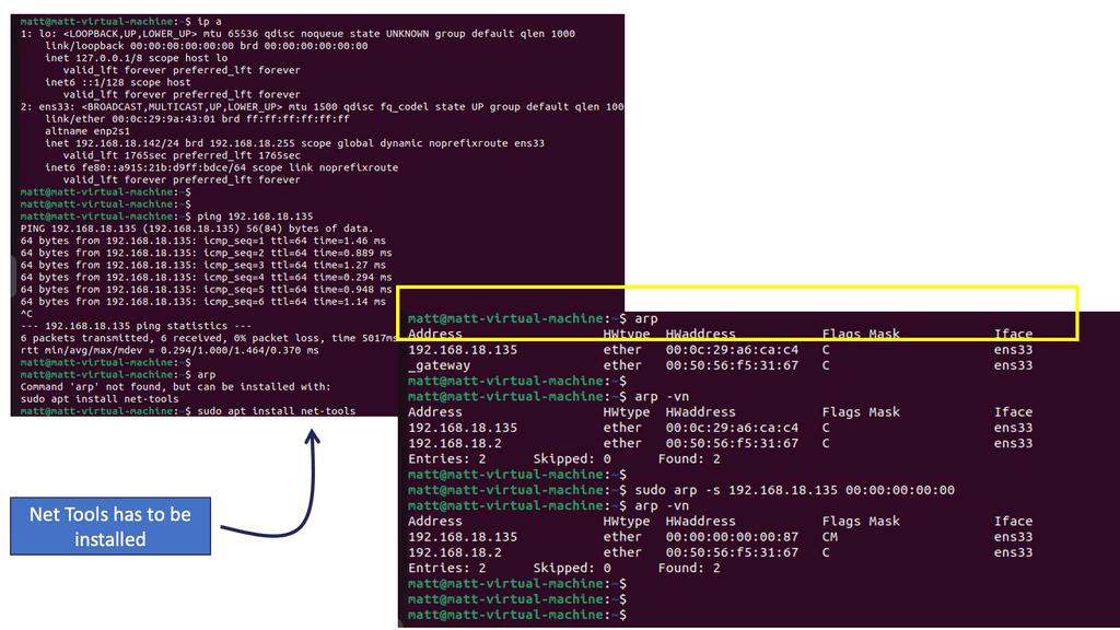
Analysis: The output contains the same columns and information, with additional information about the contents of the cache. The -v flag is for verbose mode and provides additional information about the entries in the cache. Focus on the Address. The -n flag tells the command not to resolve the address to a hostname; the result is seeing the Address as an IP.
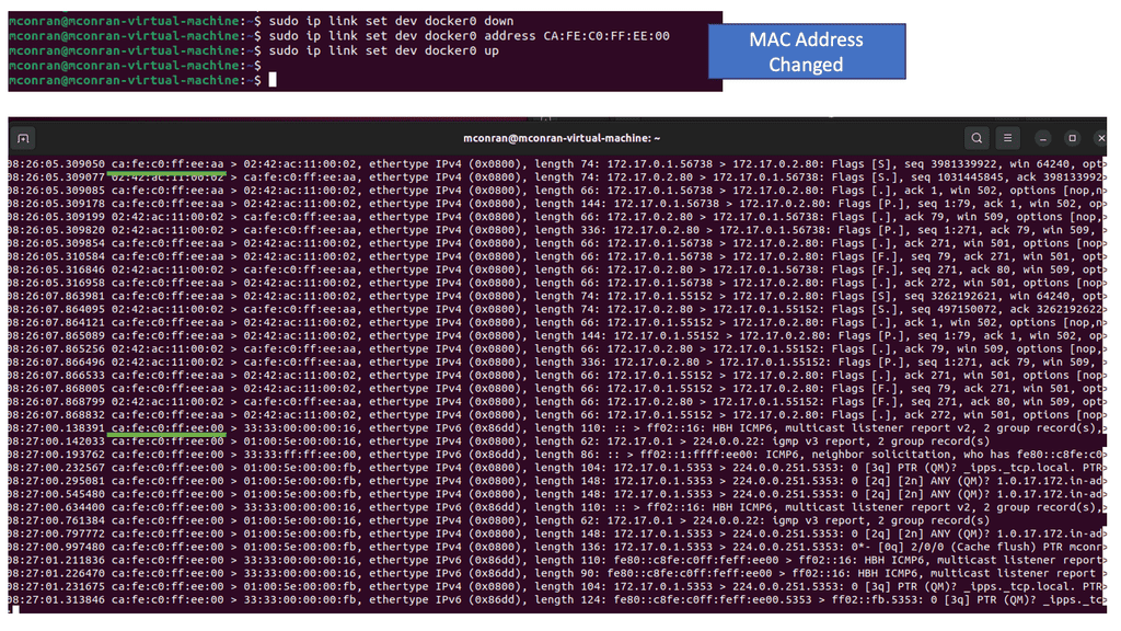
Note: The IP and Mac address returned is an additional VM running Linux in this network. This is significant because if a device is within the same subnet or layer two broadcast domain as a device identified by its local ARP cache, it will simply address traffic to the designated MAC address. In this way, if you can change the ARP cache, you can change where the device sends traffic within its subnet.
Locally, you can change the ARP cache directly by adding entries yourself. See the screenshot above:
Analysis: Now you see the original entry and the entry you just set within the local ARP cache. When your device attempts to send traffic to the address 192.168.18.135, the packets will be addressed at layer 2 to the corresponding MAC address from this table. Generally, MAC address to IP address mappings are learned dynamically through the ARP network protocol activity, indicated by the “C” under the Flags Mask column. The CM reflects that the entry was manually added.
Note: Additional Information on ARP
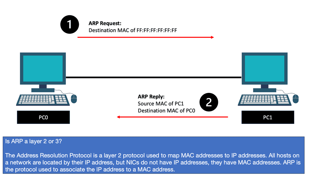
- ARP Request and Response
When a device needs to communicate with another device on the same network, it initiates an ARP request. The requesting device broadcasts an ARP request packet containing the target IP address for which it seeks the MAC address. The device with the matching IP address responds with an ARP reply packet, providing its MAC address. This exchange allows the requesting device to update its ARP table and establish a direct communication path.
- ARP Cache Poisoning
While ARP serves a critical purpose in networking, it is vulnerable to attacks like ARP cache poisoning. In this type of attack, a malicious entity spoofs its MAC address, tricking devices on the network into associating an incorrect MAC address with an IP address. This can lead to various security issues, including interception of network traffic, data manipulation, and unauthorized access.
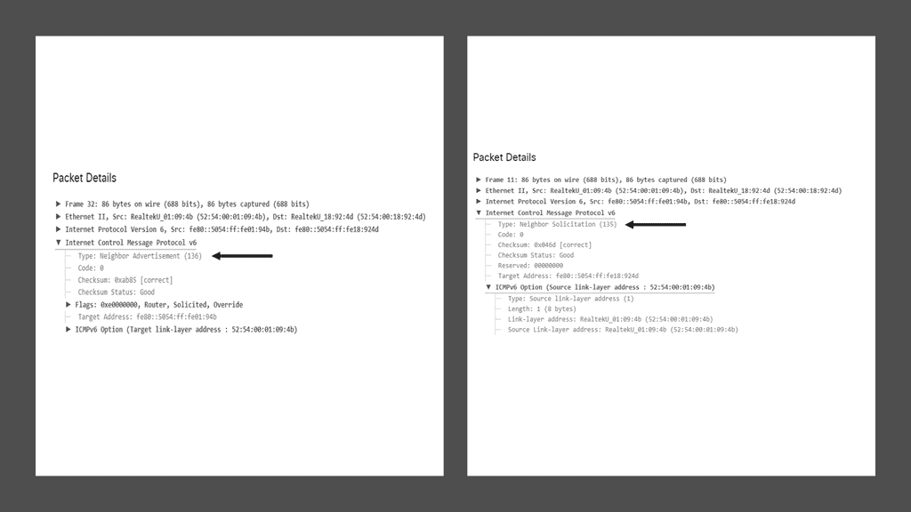
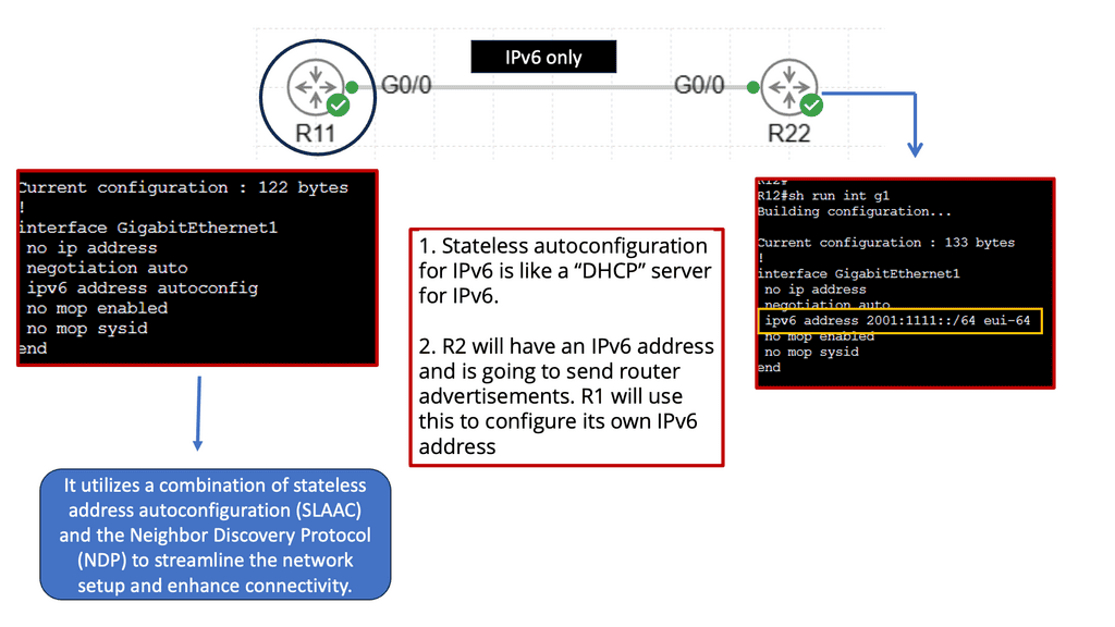
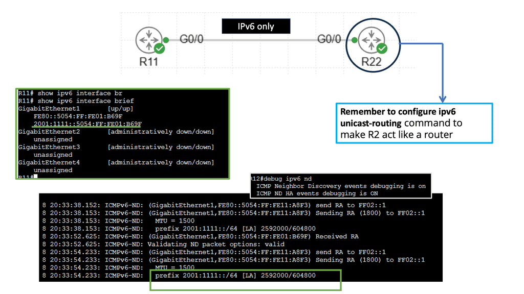
- Address Resolution Protocol in IPv6
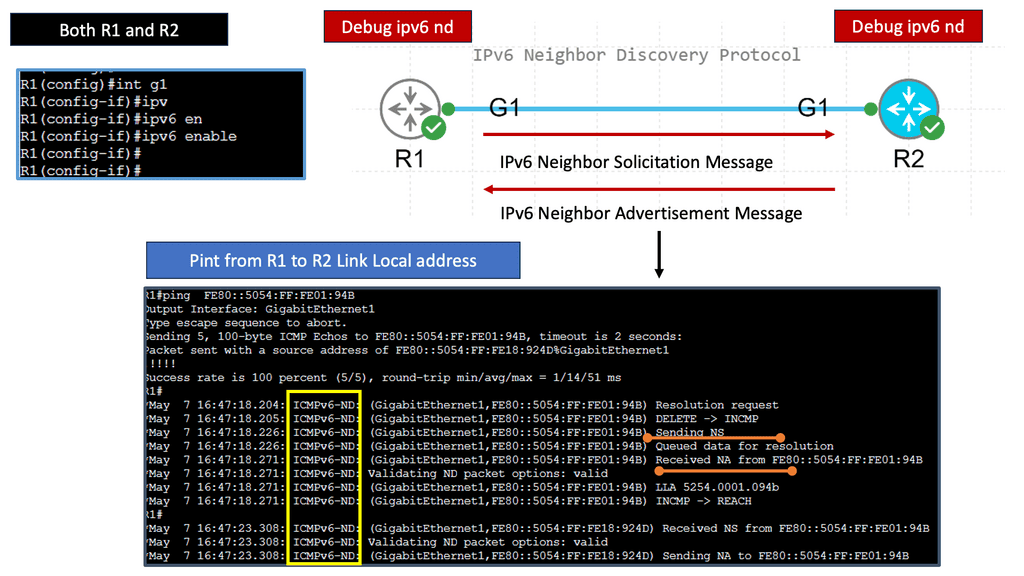
While ARP is predominantly used in IPv4 networks, IPv6 networks utilize a similar protocol called Neighbor Discovery Protocol (NDP). NDP performs functions identical to ARP but with additional features such as stateless address autoconfiguration and duplicate address detection. Although NDP differs from ARP in several ways, its purpose of mapping IP addresses to link-layer addresses remains the same.
Computer Networking & Data Traffic
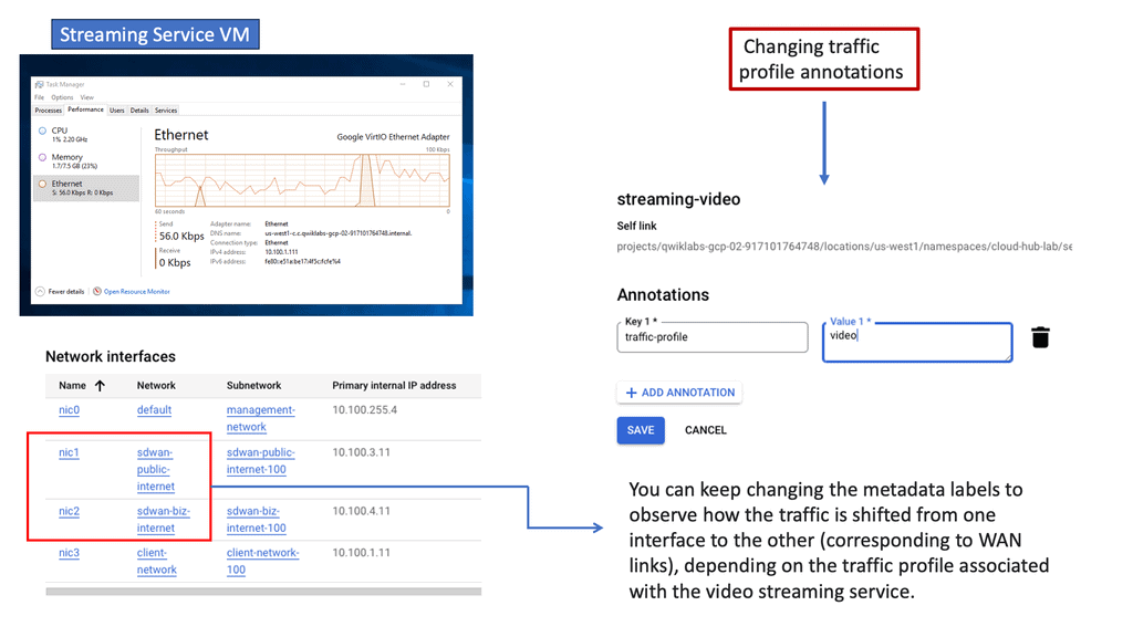
Computer networking aims to carry data traffic so we can share resources. The first use case of computer networks was to share printers; now, we have a variety of use cases that evolve around data traffic. Data traffic can be generated from online activities such as streaming videos, downloading files, surfing the web, and playing online games. It is also generated from behind-the-scenes activities such as system updates and background and software downloads.
The Importance of Data Traffic
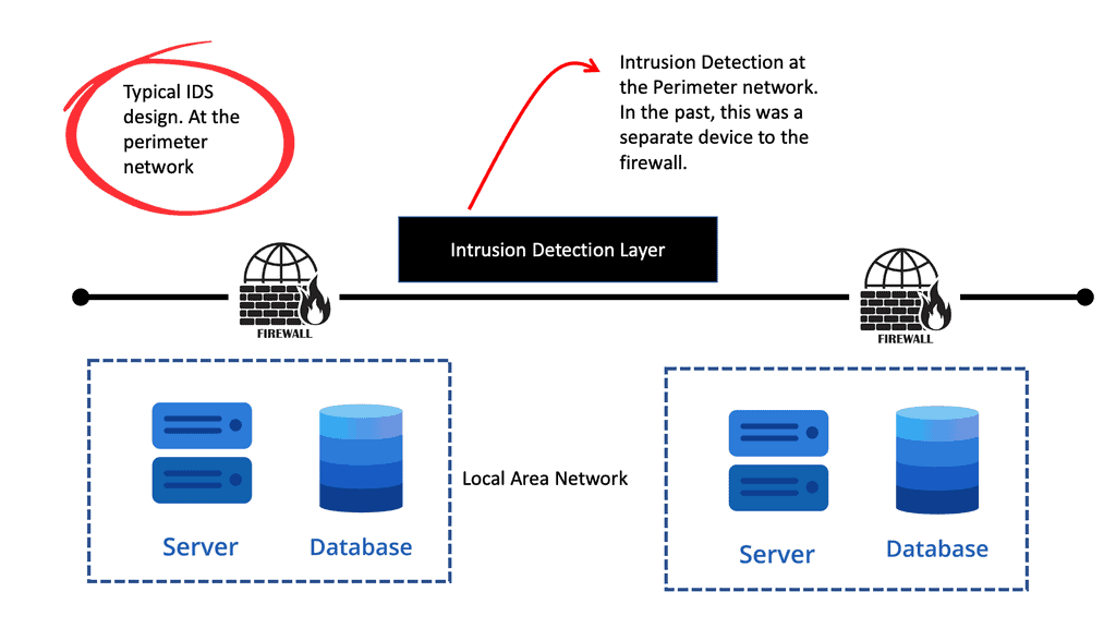
Data traffic is the amount transmitted over a network or the Internet. It is typically measured in bits, bytes, and packets per second. Data traffic can be both inbound and outbound. Inbound traffic is data coming into a network or computer, and outbound traffic is data leaving a network or computer. Inbound data traffic should be inspected by a security device, such as a firewall, which can either be at the network’s perimeter or on your computing device. At the same time, outbound traffic is generally unfiltered.
To keep up with the increasing demand, companies must monitor data traffic to ensure the highest quality of service and prevent network congestion. With the right data traffic monitoring tools and strategies, organizations can improve network performance and ensure their data is secure.
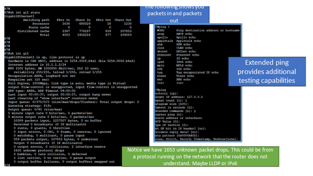
The Issues of Best Efforts or FIFO
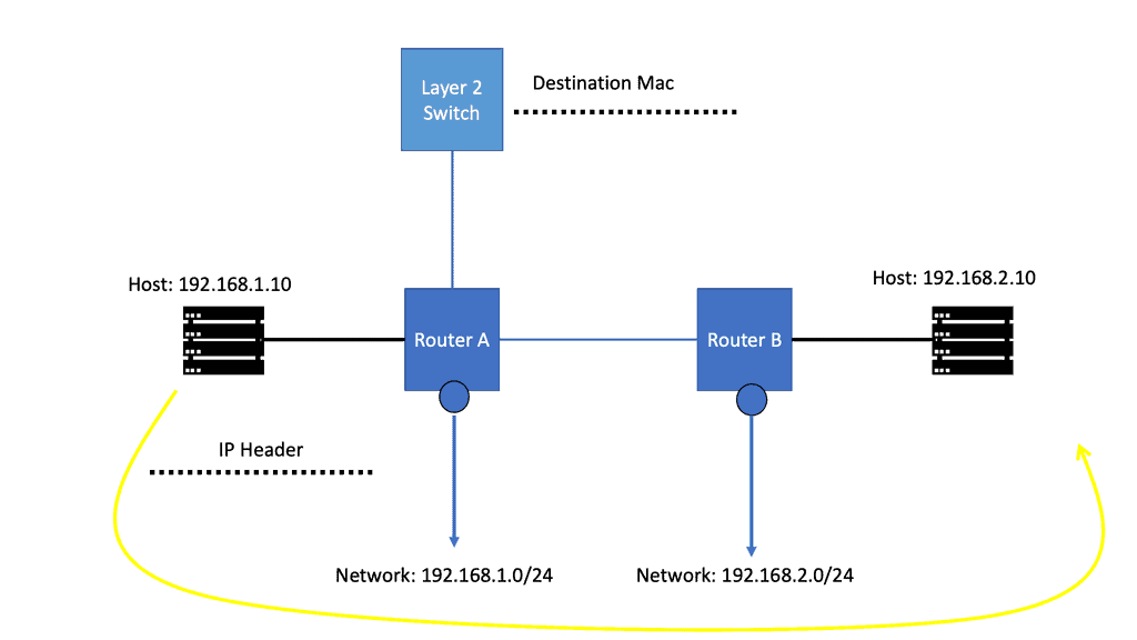
Network devices don’t care what kind of traffic they have to forward. Ethernet frames are received by your switch, which looks for the destination MAC address before forwarding them. Your router does the same thing: it gets an IP packet, checks the routing table for the destination, and forwards the packet.
Would the frame or packet contain data from a user downloading the latest songs from Spotify or significant speech traffic from a VoIP phone? It doesn’t matter to the switch or router. This forwarding logic is called best effort or FIFO (First In, First Out). Sometimes, this can be an issue when applications are hungry for bandwidth.
Example: Congestion
The serial link is likely congested when the host and IP phone transmit data and voice packets to the host and IP phone on the other side. Packets queued for transmission will not be indefinitely held by the router.
When the queue is full, how should the router proceed? Are data packets being dropped? Voice packets? If voice packets are dropped, there will be complaints about poor voice quality on the other end. If data packets are dropped, users may complain about slow transfer speeds.
You can change how the router or switch handles packets using QoS tools. For example, the router can prioritize voice traffic over data traffic.
The Role of QoS
Quality of Service (QoS) is a popular technique used in computer networking. QoS can segment applications so that different types will have different priority levels. For example, Voice traffic is often considered more critical than web surfing traffic. Especially as it is sensitive to packet loss. So, when there is congestion on the network, QoS allows administrators to prioritize network traffic so users have the best experience.
Quality of Service (QoS) refers to techniques and protocols prioritizing and managing network traffic. By allocating resources effectively, QoS ensures that critical applications and services receive the necessary bandwidth, low latency, and minimal packet loss while maintaining a stable network connection. This optimization process considers factors such as data type, network congestion, and the specific requirements of different applications.
Expedited Forwarding (EF)
Expedited Forwarding (EF) is a network traffic management model that provides preferential treatment to certain types of traffic. The EF model prioritizes traffic, specifically real-time traffic such as voice, video, and streaming media, over other types of traffic, such as email and web browsing. This allows these real-time applications to function more reliably and efficiently by reducing latency and jitter.
The EF model works by assigning a traffic class to each data packet based on the type of data it contains. The assigned class dictates how the network treats the packet. The EF model has two categories: EF for real-time traffic and Best Effort (BE) for other traffic. EF traffic is given preferential treatment, meaning it is prioritized over BE traffic, resulting in a higher quality of service for the EF traffic.
The EF model is an effective and efficient way to manage computer network traffic. By prioritizing real-time traffic, the EF model allows these applications to function more reliably, with fewer delays and a higher quality of service. Additionally, the EF model is more efficient, reducing the amount of traffic that needs to be managed by the network.
Lab Guide: QoS and Marking Traffic
TOS ( Type of Service )
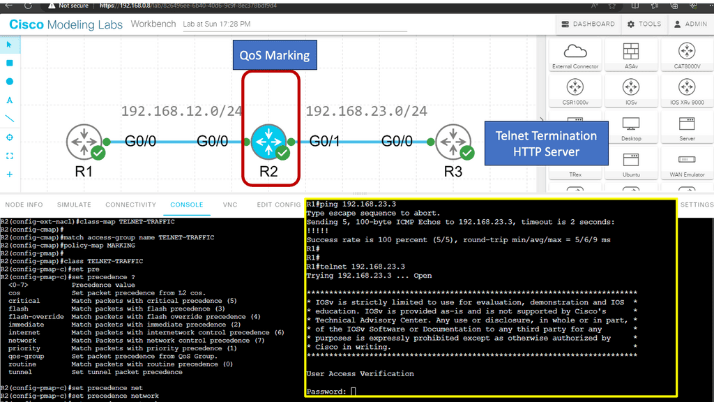
In this Lab, we’ll take a look at marking packets. Marking means we set the TOS (Type of Service) byte with an IP Precedence or DSCP value.
Marking and Classifcaiton take place on R2. R1 is the source of the ICMP and HTTP Traffic. R3 has an HTTP server installed. As traffic, both telnet and HTTP packets get sent from R1 and traverse R2, classification takes place.
Note:
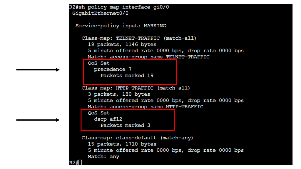
To ensure each application gets the treatment it requires, we must implement QoS (Quality of Service). The first step when implementing QoS is classification,
We will mark the traffic and apply a QoS policy once it has been classified. Marking and configuring QoS policies are a whole different story, so we’ll stick to classification in this lesson.
On IOS routers, there are a couple of methods we can use for classification:
- Header inspection
- Payload inspection
We can use some fields in our headers to classify applications. For example, telnet uses TCP port 23, and HTTP uses TCP port 80. Using header inspection, you can look for:
- Layer 2: MAC addresses
- Layer 3: source and destination IP addresses
- Layer 4: source and destination port numbers and protocol
♦Benefits of Quality of Service
A) Bandwidth Optimization:
One of the primary advantages of implementing QoS is the optimized utilization of available bandwidth. By classifying and prioritizing traffic, QoS ensures that bandwidth is allocated efficiently, preventing congestion and bottlenecks. This translates into smoother and uninterrupted network experiences, especially when multiple users or devices access the network simultaneously.
B) Enhanced User Experience:
With QoS, users can enjoy a seamless experience across various applications and services. Whether streaming high-quality video content, engaging in real-time online gaming, or participating in video conferences, QoS helps maintain low latency and minimal jitter, resulting in a smooth and immersive user experience.
♦Implementing Quality of Service
To implement QoS effectively, network administrators need to understand the specific requirements of their network and its users. This involves:
A) Traffic Classification:
Different types of network traffic require different levels of priority. Administrators can allocate resources by classifying traffic based on its nature and importance.
B) Traffic Shaping and Prioritization:
Once traffic is classified, administrators can prioritize it using various QoS mechanisms such as traffic shaping, packet queuing, and traffic policing. These techniques ensure critical applications receive the necessary resources while preventing high-bandwidth applications from monopolizing the network.
C) Monitoring and Fine-Tuning:
Regular monitoring and fine-tuning of QoS parameters are essential to maintain optimal network performance. By analyzing network traffic patterns and adjusting QoS settings accordingly, administrators can adapt to changing demands and ensure a consistently high level of service.
Computer Networking Components – Devices:
First, the devices. Media interconnect devices provide the channel over which the data travels from source to destination. Many devices are virtualized today, meaning they no longer exist as separate hardware units.
One physical device can emulate multiple end devices. In addition to having its operating system and required software, an emulated computer system operates as a separate physical unit. Devices can be further divided into endpoints and intermediary devices.
Endpoint:
Endpoint is a device part of a computer network, including PCs, laptops, tablets, smartphones, video game consoles, and televisions. Endpoints can be physical hardware units, such as file servers, printers, sensors, cameras, manufacturing robots, and smart home components. Nowadays, we have virtualized endpoints.
Computer Networking Components – Intermediate Devices
Layer 2 Switches:
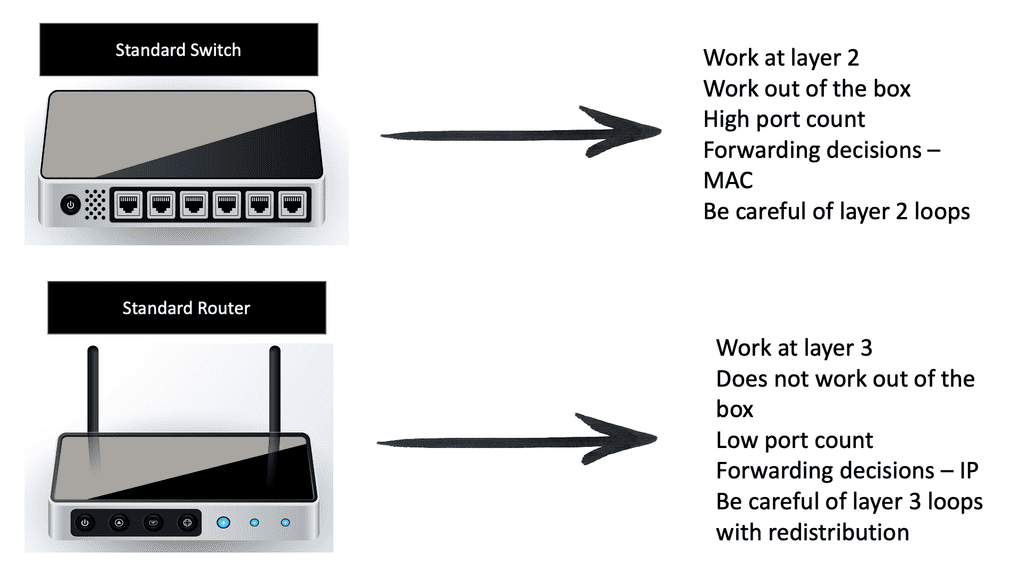
These devices enable multiple endpoints, such as PCs, file servers, printers, sensors, cameras, and manufacturing robots, to connect to the network. Switches allow devices to communicate on the same network. Switches attempt to forward messages from the sender so the destination can only receive them, unlike a hub that floods traffic out of all ports. The switch operates with MAC addresses and works at Layer 2 of the OSI model.
Usually, all the devices that connect to a single switch or a group of interconnected switches belong to a standard network. They can, therefore, exchange information directly with each other. If an end device wants to communicate with a device on a different network, it requires the “services” of a device known as a router. Routers connect other networks and work higher up in the OSI model at Layer 3. They use the IP protocol.
Routers:
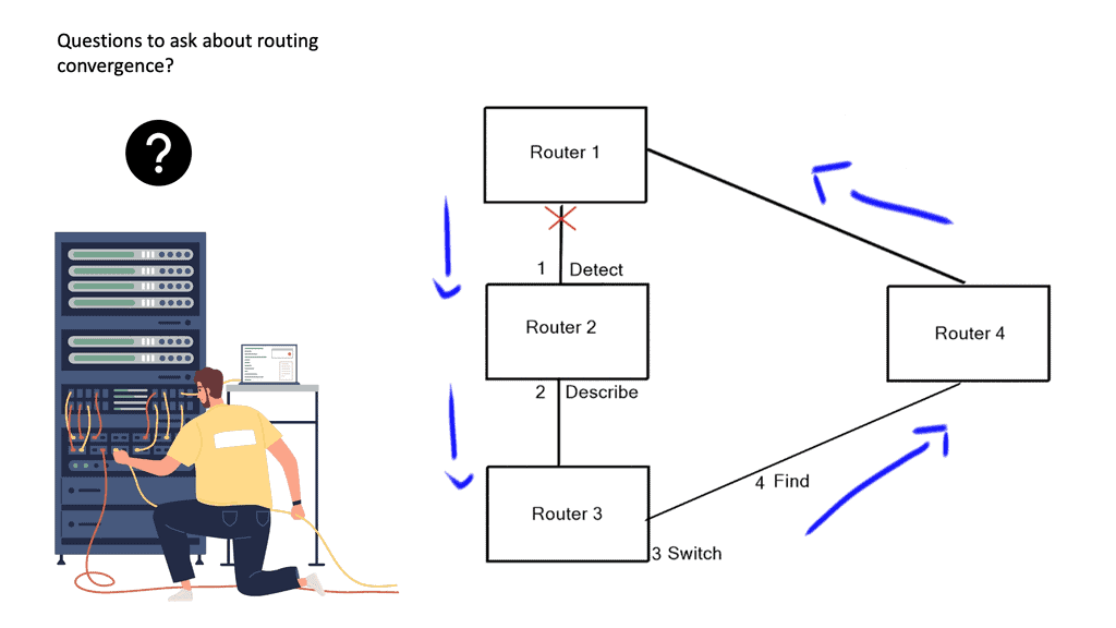
Routers’ primary function is to route traffic between computer networks. For example, you need a router to connect your office network to the Internet. Routers connect computer networks and intelligently select the best paths between them, and they hold destinations in what is known as a routing table. There are different routing protocols for different-sized networks, and each will have other routing convergence times.
We recently combined Layer 2 and Layer 3 functionality. So we have a Layer 3 router with a Layer 2 switch module inserted, or we can have a multilayer switch that combines the functions of Layer 3 routing and Layer 2 switch functionality on a single device.
Wi-Fi access points:
These devices allow wireless devices to connect. They usually connect to switches but can also be integrated into routers. My WAN router has everything in one box: Wi-Fi, Ethernet LAN, and network services such as NAT and WAN. Wi-Fi access points provide wireless internet access within a specified area.
Wi-Fi access points are typically found in coffee shops, restaurants, libraries, and airports in public settings. These access points allow anyone with a Wi-Fi-enabled device to access the Internet without needing additional hardware.
WLAN controllers:
WLAN controllers are devices used to automate the configuration of wireless access points. They provide centralized management of wireless networks and act as a gateway between wireless and wired networks. Administrators can monitor and manage the entire WLAN, set up security policies, and configure access points through the controller. WLAN controllers also authenticate users, allowing them to access the wireless network.
In addition, the WLAN controller can also detect and protect against malicious activities such as unauthorized access, denial-of-service attacks, and interference from other wireless networks. By using the controller, administrators can also monitor the usage of the wireless network and make sure that the network is secure.
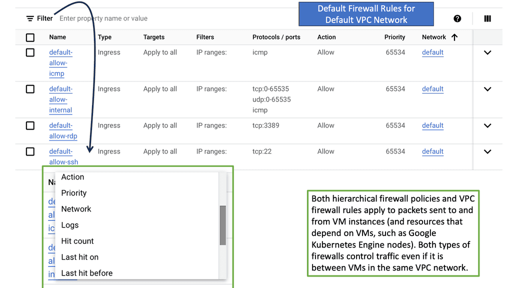
Network firewalls:
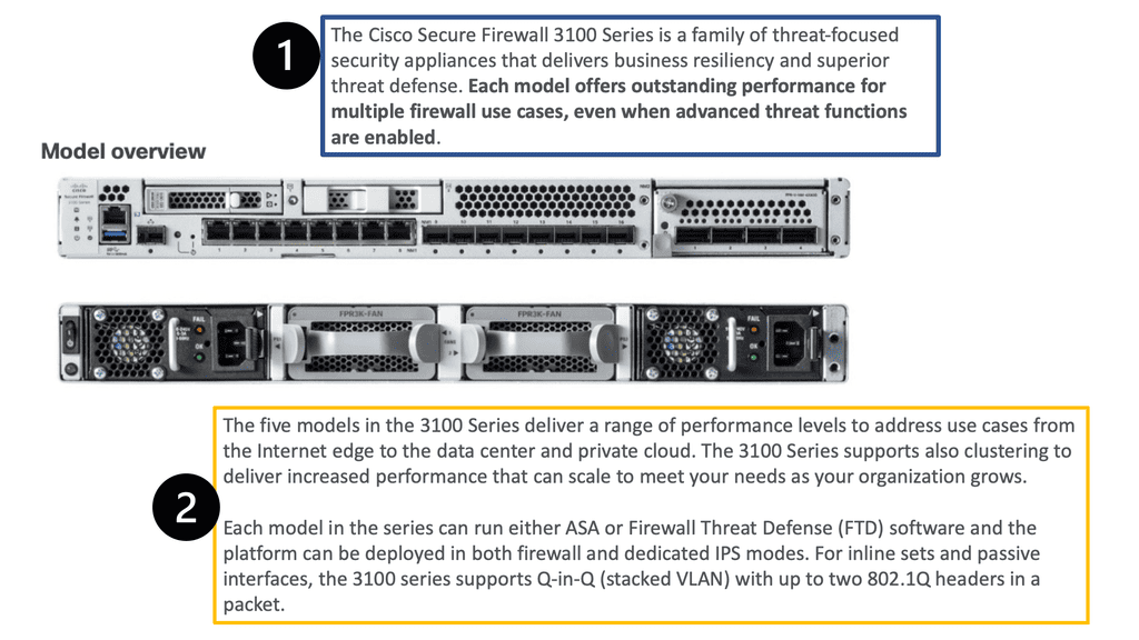
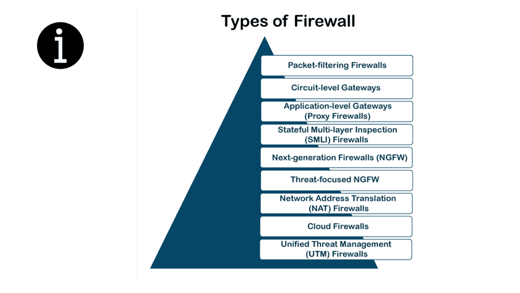
Then, we have firewalls, which are the cornerstone of security. Depending on your requirements, there will be different firewall types. Firewalls range from basic packet filtering to advanced next-generation firewalls and come in virtual and physical forms.
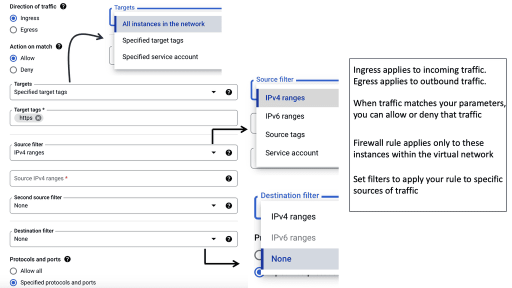
Generally, a firewall monitors and controls incoming and outgoing traffic according to predefined security rules. The firewall will have a default rule set so that some firewall interfaces are more trusted than others, blankly restricting traffic from outside to inside, but you need to set up a policy for firewalls to work.
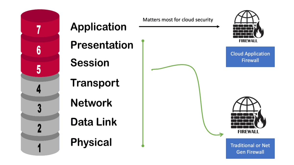
A firewall typically establishes a barrier between a trusted, secure internal network and another outside network, such as the Internet, which is assumed not to be secure or trusted. Firewalls are typically deployed in a layered approach, meaning multiple security measures are used to protect the network. Firewalls provide application, protocol, and network layer protection.
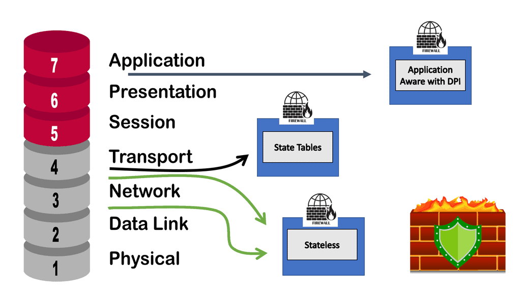
- Application layer protection:
The next layer is the application layer, designed to protect the network from malicious applications, such as viruses and malware. The application layer also includes software like firewalls to detect and block malicious traffic.
- Protocol layer protection:
The third layer is the protocol layer. This layer focuses on ensuring that the data traveling over a network is encrypted and that it is not allowed to be modified or corrupted in any way. This layer also includes authentication protocols that prevent unauthorized users from accessing the network.
- Network Layer protection
Finally, the fourth layer is network layer protection. This layer focuses on controlling access to the network and ensuring that users cannot access resources or applications they are not authorized to use.
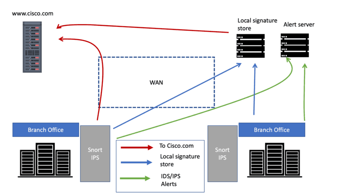
A network intrusion protection system (IPS):
An IPS or IDS analyzes network traffic to search for signs that a particular behavior is suspicious or malicious. If the IPS detects such behavior, it can take protective action immediately. In addition, the IPS and firewall can work together to protect a network. So, if an IPS detects suspicious behavior, it can trigger a policy or rule for the firewall to implement.
An intrusion protection system can alert administrators of suspicious activity, such as attempts to gain unauthorized access to confidential files or data. Additionally, it can block malicious activity if necessary; it provides a layer of defense against malicious actors and cyber attacks. Intrusion protection systems are essential to any organization’s security plan.
Computer Networking Components – Media
Next, we have the media. The media connects network devices. Different media have different characteristics, and selecting the most appropriate medium depends on the circumstances, including the environment in which the media is used and the distances that need to be covered.
The media will need some connectors. A connector makes it much easier to connect wired media to network devices. A connector is a plug attached to each end of the cable. RJ-45 connector is the most common type of connector on an Ethernet LAN.
Ethernet: Wired LAN technology.
The term Ethernet refers to an entire family of standards. Some standards define how to send data over a particular type of cabling and at a specific speed. Other standards define protocols or rules that the Ethernet nodes must follow to be a part of an Ethernet LAN. All these Ethernet standards come from the IEEE and include 802.3 as the beginning of the standard name.
Introducing Copper and Fiber
Ethernet LANs use cables for the links between nodes on a computer network. Because many types of cables use copper wires, Ethernet LANs are often called wired LANs. Ethernet LANs also use fiber-optic cabling, which includes a fiberglass core that devices use to send data using light.
Materials inside the cable: UTP and Fiber
The most fundamental cabling choice concerns the materials used inside the cable to transmit bits physically: either copper wires or glass fibers.
- Unshielded twisted pair (UTP) cabling devices transmit data over electrical circuits via the copper wires inside the cable.
- Fiber-optic cabling, the more expensive alternative, allows Ethernet nodes to send light over glass fibers in the cable’s center.
Although more expensive, optical cables typically allow longer cabling distances between nodes. So you have UTP cabling in your LAN and Fiber-optic cabling over the WAN.
UTP and Fiber
The most common copper cabling for Ethernet is UTP. An unshielded twisted pair (UTP) is cheaper than the other two and is easier to install and troubleshoot. Many UTP-based Ethernet standards can use a cable length of up to 100 meters, which means that most Ethernet cabling in an enterprise uses UTP cables.
The distance from an Ethernet switch to every endpoint on a building’s floor will likely be less than 100m. In some cases, however, an engineer might prefer to use fiber cabling first for some links in an Ethernet LAN to reach greater distances.
Fiber Cabling
Then we have fiber-optic cabling, a glass core that carries light pulses and is immune to electrical interference. Fiber-optic cabling is typically used as a backbone between buildings. So fiber cables are high-speed transmission mediums. It contains tiny glass or plastic filaments as the medium to which light passes.
Cabling types: Multimode and Single Mode
There are two main types of fiber optic cables. We have single-mode fiber ( SMF) and multimode fiber ( MMF). Two implementations of fiber-optic include MMF for shorter distances and SMF for longer distances. Multimode improves the maximum distances over UTP and uses less expensive transmitters than single-mode. Standards vary; for instance, the criteria for 10 Gigabit Ethernet over Fiber allow for distances up to 400m, often allowing for connecting devices in different buildings in the same office park.
Network Services and Protocols
We need to follow these standards and the rules of the game. We also need protocols so we have the means to communicate. If you use your web browser, you use the HTTP protocol. If you send an email, you use other protocols, such as IMAP and SMTP.
A protocol establishes a set of rules that determine how data is transmitted between different devices in the network. The two protocols must talk to each other, such as HTTP at one end and HTTP at the other.
Consider protocol the same way you would speak the same language. We need to communicate in the same language. Then, we have standards that we need to follow for computer networking, such as the TCP/IP suite.
Types of protocols
We have different types of protocols. The following are the main types of protocols used in computer networking.
- Communication Protocols
For example, we have routing protocols on our routers that help you forward traffic. This would be an example of a communication protocol that allows different devices to communicate with each other. Another example of a communication protocol would be instant messaging.
Instant messaging is instantaneous, text-based communication you probably have used on your smartphone. So here we have several instant messaging network protocols. Short Message Service (SMS): This communications protocol was created to send and receive text messages over cellular networks.
- Network Management
Network management protocols define and describe the various operating procedures of a computer network. These protocols affect multiple devices on a single network—including computers, routers, and servers—to ensure that each one and the network as a whole perform optimally.
- Security Protocols
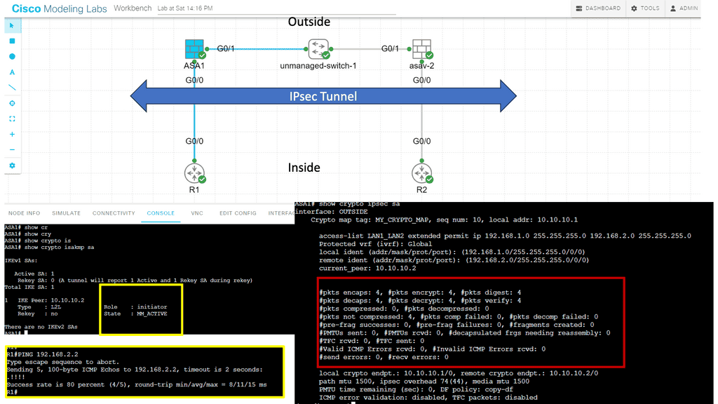
Security protocols, also called cryptographic protocols, ensure that the network and the data sent over it are protected from unauthorized users. Security protocols are implemented on more than just your network security devices. They are implemented everywhere. The standard functions of security network protocols include encryption: Encryption protocols protect data and secure areas by requiring users to input a secret key or password to access that information.
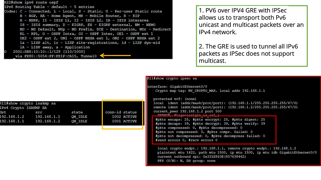
The following screenshot is an example of an IPsec tunnel offering end-to-end encryption. Notice that the first packet in the ping ( ICMP request ) was lost due to ARP working in the background. Five pings are sent, but only four are encapsulated/decapsulated.
Characteristics of a network
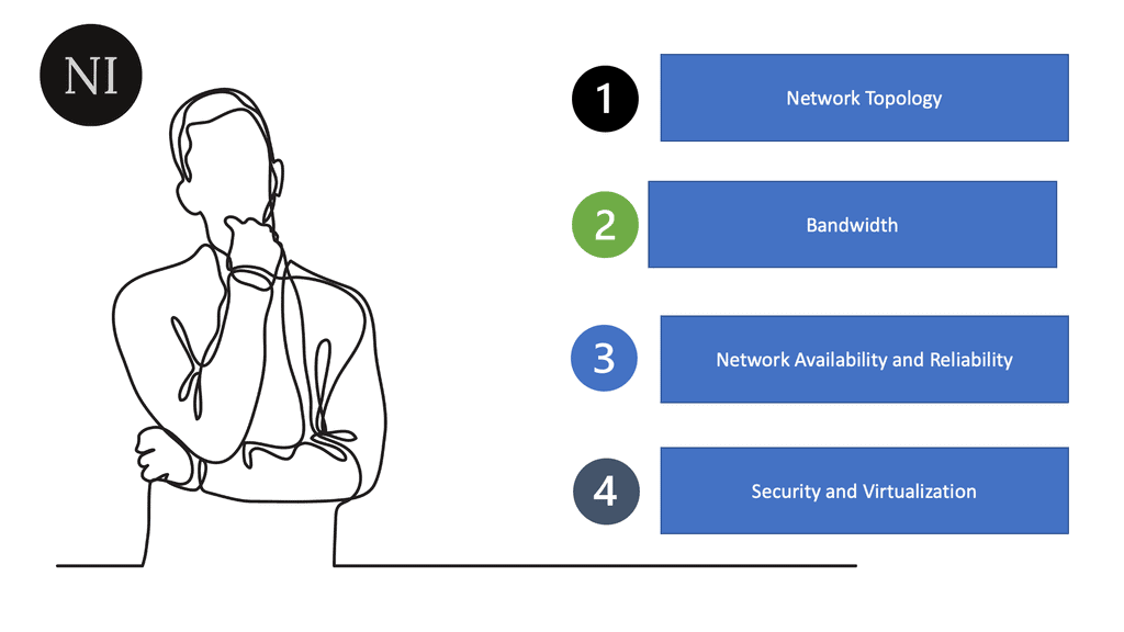
Network Topology:
In a carefully designed network, data flows are optimized, and the network performs as intended based on the network topology. Network topology is the arrangement of a computer network’s elements (links, nodes, etc.). It can be used to illustrate a network’s physical and logical layout and how it functions.
Bitrate or Bandwidth:
It is often referred to as bandwidth or speed in device configurations, sometimes considered speed. Bitrate measures the data rate in bits per second (bps) of a given link in the network. The number of bits transmitted in a second is more important than the speed at which one bit is transmitted over the link – which is determined by the physical properties of the medium that propagates the signal. Many link bit rates are commonly encountered today, including 1 and 10 gigabits per second (1 and 10 billion bits per second). Some links can reach 100 and even 400 gigabits per second.
Network Availability:
Network availability is determined by several factors, including the type of network being used, the number of users, the complexity of the network, the physical environment, and the availability of network resources. Network availability should also be addressed in terms of redundancy and backup plans. Redundancy helps to ensure that the system is still operational even if one or more system components fail. Backup plans should also be in place in the event of a system failure.
A network’s availability is calculated based on the percentage of time it is accessible and operational. To calculate this percentage, divide the number of minutes the network is available by the total number of minutes it is available for over an agreed period and divide it by 100. In other words, availability is the ratio of uptime and full-time, expressed in percentage.
Network High Availability:
High availability is a critical component of a successful IT infrastructure. It ensures that systems and services remain available and accessible to users and customers. High availability is achieved by using redundancies, such as multiple servers, systems, and networks, to ensure that if one component fails, a backup component is available.
High availability is also achieved through fault tolerance, which involves designing systems that respond to failures without losing data or becoming unavailable. Various strategies, such as clustering, virtualization, and replication, can achieve high availability.
Network Reliability:
Network reliability can be achieved by implementing a variety of measures, often through redundancy. Redundancy is a crucial factor in ensuring a reliable network. Redundancy has multiple components to provide a backup in case of failure. Redundancy can include having multiple servers, routers, switches, and other hardware devices. Redundancy can also involve having numerous sources of power, such as various power supplies or batteries, and multiple paths for data to travel through the network.
For adequate network reliability, you also need to consider network monitoring. Network monitoring involves using software and hardware tools to monitor the network’s performance continuously. Monitoring can detect and alert administrators of potential performance issues or failures. We have a new term called Observability, which accurately reflects tracking in today’s environment.
Network Scalability:
A network’s scalability indicates how easily it can accommodate more users and data transmission requirements without affecting performance. Designing and optimizing a network only for the current conditions can make it costly and challenging to meet new needs when the network grows.
Several factors must be taken into account in terms of network scalability. First and foremost, the network must be designed with the expectation that the number of devices or users will increase over time. This includes hardware and software components, as the network must support the increased traffic. Additionally, the network must be designed to be flexible so that it can easily accommodate changes in traffic or user count.
Network Security:
Network security is protecting the integrity and accessibility of networks and data. It involves a range of protective measures designed to prevent unauthorized access, misuse, modification, or denial of a computer network and its processing data. These measures include physical security, technical security, and administrative security. A network’s security tells you how well it protects itself against potential threats.
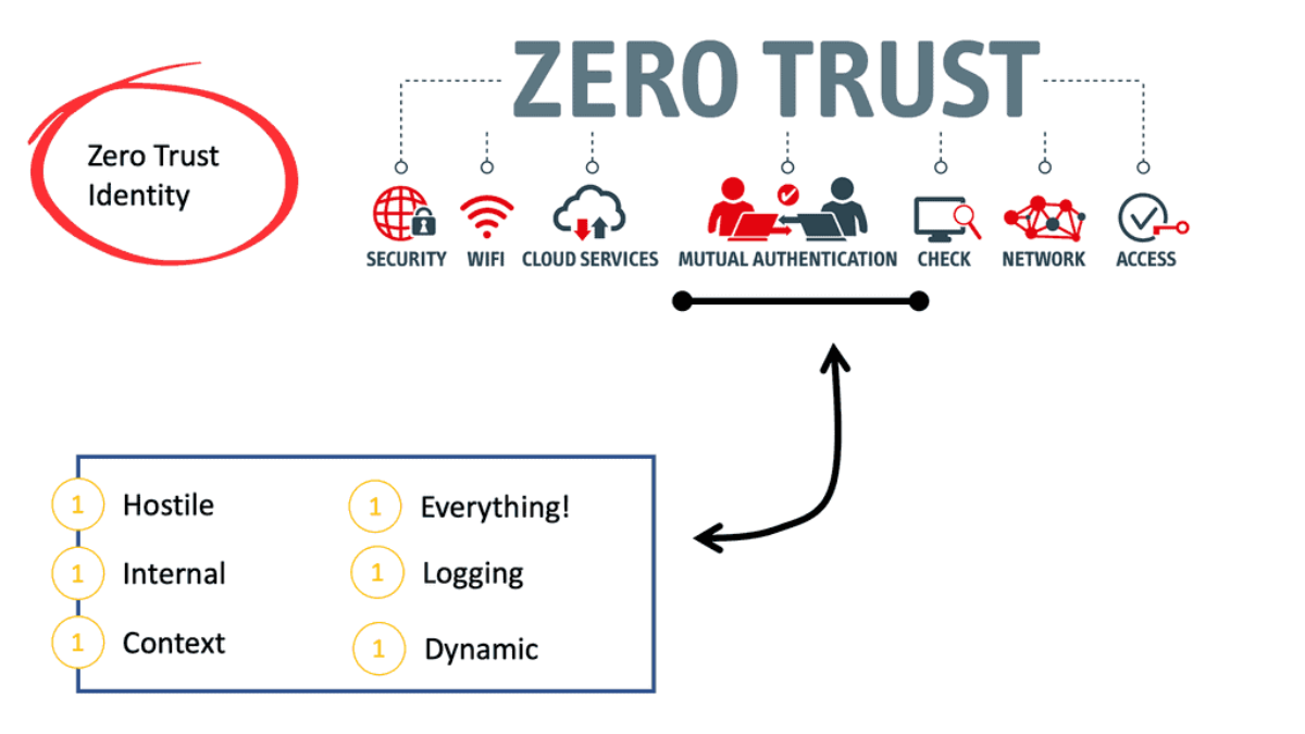
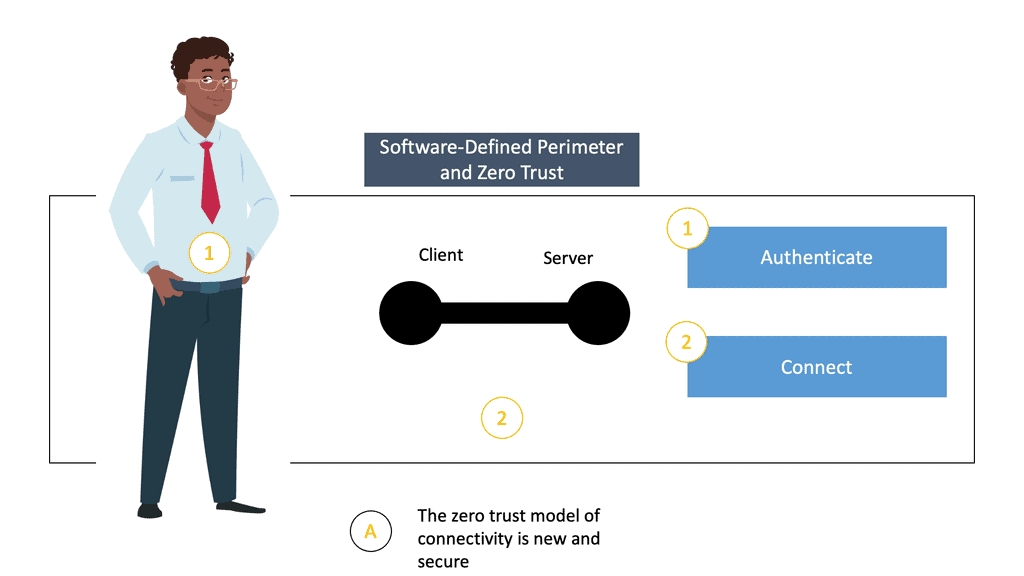
The subject of security is essential, and defense techniques and practices are constantly evolving. The network infrastructure and the information transmitted over it should also be protected. Whenever you take actions to affect the network, you should consider security. An excellent way to view network security is to take a zero-trust approach.
Virtualization:
Virtualization can be done at the hardware, operating system, and application level. At the hardware level, physical hardware can be divided into multiple virtual machines, each running its operating system and applications.
At the operating system level, virtualization can run multiple operating systems on the same physical server, allowing for more efficient resource use. At the application level, multiple applications can run on the same operating system, allowing for better resource utilization and scalability.
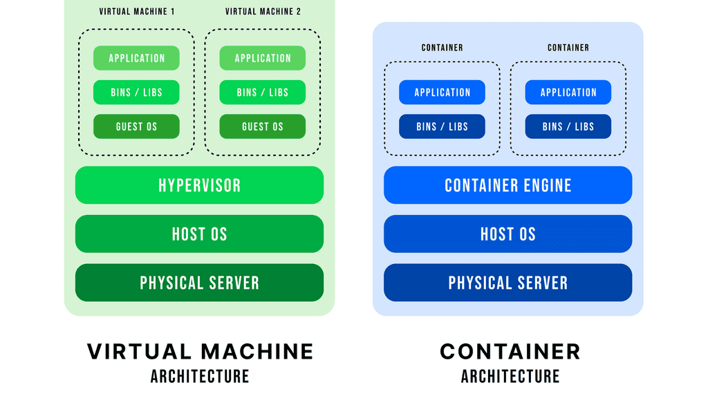
Overall, virtualization can provide several benefits, including improved efficiency, utilization, flexibility, security, and scalability. It can consolidate and manage hardware or simplify application movement between different environments. Virtualization can also make it easier to manage other settings and provide better security by isolating various applications.
Computer Networking Characteristics of a Network |
|
Computer Networking and Network Topologies
Physical and logical topologies exist in networks. The physical topology describes the physical layout of the devices and cables. A physical topology may be the same in two networks but may differ in distances between nodes, physical connections, transmission rates, or signal types.
There are various types of physical topologies you may encounter in wired networks. Identifying the kind of cabling used is essential when describing the physical topology. Physical topology can be categorized into the following categories:
Bus Topology:
In a bus topology, every workstation is connected to a common transmission medium, a single cable called a backbone or bus. In a previous bus topology, computers and other network devices were connected to a central coaxial cable via connectors, resulting in direct connectivity.
Ring Topology:
In a ring topology, computers and other network devices are cabled in succession, with the last device connected to the first to form a circle or ring. There are two neighbors for every device in the network, and there are no direct connections between them. When one node sends data to another, it passes through each node between them until it reaches its destination.
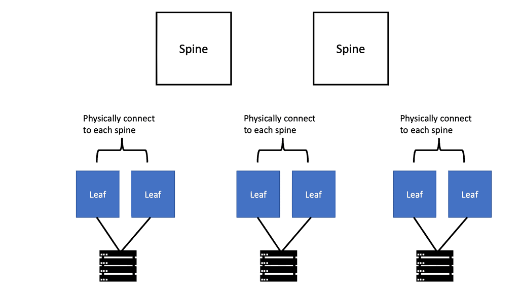
- Star Topology:
A star topology is the most common physical topology, where network devices are connected to a central device through point-to-point connections. It is also known as the hub and spoke topology. A spoke device does not have a direct physical connection to another. This topology can also be called the extended star topology. A device with its spokes replaces one or more spoke devices in an extended star topology.
Mesh Topology:
One device can be connected to more than one other in a mesh topology. Multiple paths are available for one node to reach another. Redundant links enhance reliability and self-healing. In a full mesh topology, all nodes are connected. In partial mesh, some nodes do not connect to all other nodes.
Introducing Switching Technologies
All Layer 2 devices connect to switches to communicate with one another. Switches work at layer two of the Open Systems Interconnection (OSI) model, the data link layer. Switches are ready to use right out of the box. In contrast to a router, a switch doesn’t require configuration settings by default. When you unbox the switch, it does not need to be configured to perform its role, which is to provide connectivity for all devices on your network. After putting power on the switch and connecting the systems, the switch will forward traffic to each connected device as needed.
Switch vs. Hubs
Moreover, you learned that switches had replaced hubs since they provide more advanced capabilities and are better suited to today’s computer networks. Advanced functionality includes filtering traffic by sending data only to the destination port (while a hub always sends data to all ports).
Full Duplex vs. Half Duplex
With a full duplex, both parties can talk and listen simultaneously, making it more efficient than half-duplex communication, where only one can speak simultaneously. Full duplex transmission is also more reliable since it is less likely to experience interference or distortion. Until switches became available, communication devices were only half-duplexed with hubs. A half-duplex device can send and receive simultaneously, but not simultaneously send and receive.
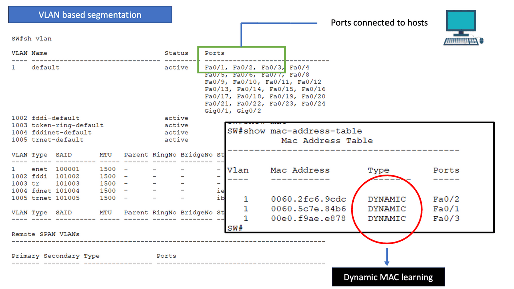
VLAN: Logical LANs
Virtual Local Area Networks (VLANs) are computer networks that divide a single physical local area network (LAN) into multiple logical networks. This partitioning allows for the segmentation of broadcast traffic, which helps to improve network performance and security.
VLANs enable administrators to set up multiple networks within a single physical LAN without needing separate cables or ports. These benefits businesses need to separate data and applications between various teams, departments, or customers.
In a VLAN, each segment is identified by a unique identifier or VLAN ID. The VLAN ID is used to associate traffic with a particular VLAN segment. For example, if a user needs to access an application on a different VLAN, the packet must be tagged with the VLAN ID of the destination segment to be routed correctly.
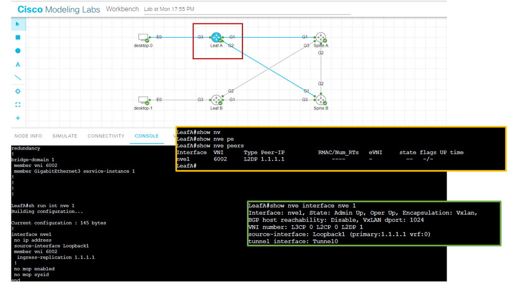
In the screenshot below, we have an overlay with VXLAN. VXLAN, short for Virtual Extensible LAN, is an overlay network technology that enables the creation of virtual Layer 2 networks over an existing Layer 3 infrastructure. It addresses traditional VLANs’ limitations by extending network virtualization’s scalability and flexibility. By encapsulating Layer 2 frames within UDP packets, VXLAN allows for creating up to 16 million logical networks, overcoming the limitations imposed by the 12-bit VLAN identifier field.
VLANs also provide security benefits. A VLAN can help prevent malicious traffic from entering a segment by segmenting traffic into logical networks. This helps prevent attackers from gaining access to the entire network. Additionally, VLANs can isolate critical or confidential data from other users on the same network. VLANs can be implemented on almost any network, including wired and wireless networks. They can also be combined with other network technologies, such as routing and firewalls, to improve security further.
Overall, VLANs are powerful tools for improving performance and security in a local area network. With the right implementation and configuration, businesses can enjoy improved performance and better protection.
Switching Technologies |
|
IP Routing Process
IP routing works by examining the IP address of each packet and determining where it should be sent. Routers are responsible for this task and use routing protocols such as RIP, OSPF, EIGRP, and BGP to decide the best route for each packet. In addition, each router contains a routing table, which includes information on the best path to a given destination.
When a router receives a packet, it looks up the destination in its routing table. If the destination is known, the router will make a forwarding decision based on the routing protocol. The router will use a default gateway to forward the packet if the destination is unknown.
To route packets successfully, routers must be configured appropriately and able to communicate with one another. They must also be able to detect any changes to the network, such as link failures or changes in network topology.
IP routing is essential to any network, ensuring packets are routed as efficiently as possible. Therefore, it is crucial to ensure that routers are correctly configured and maintained.
Routing Table
A routing table is a data table stored in a router or a networked computer that lists the possible routes a packet of data can take when traversing a network. The routing table contains information about the network’s topology and decides which route a packet should take when leaving the router or computer. Therefore, the routing table must be updated to ensure data packets are routed correctly.
The routing table usually contains entries that specify which interface to use when forwarding a packet. Each entry may have network destination addresses and associated metrics, such as the route’s cost or hop count. In addition to the destination address, each entry can include a subnet mask, a gateway address, and a list of interface addresses.
Routers use the routing table to determine which interface to use when forwarding packets. When a router receives a packet, it looks at the packet’s destination address and compares it to the entries in the routing table. Once it finds a match, it forwards the packet to the corresponding interface.
Lab Guide: Networking and Security
Routing Tables and Netstat
Routing tables are essentially databases stored within networking devices, such as routers. These tables contain valuable information about the available paths and destinations within a network. Each entry in a routing table consists of various fields, including the destination network address, next-hop address, and interface through which the data packet should be forwarded.
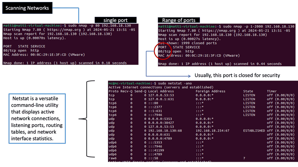
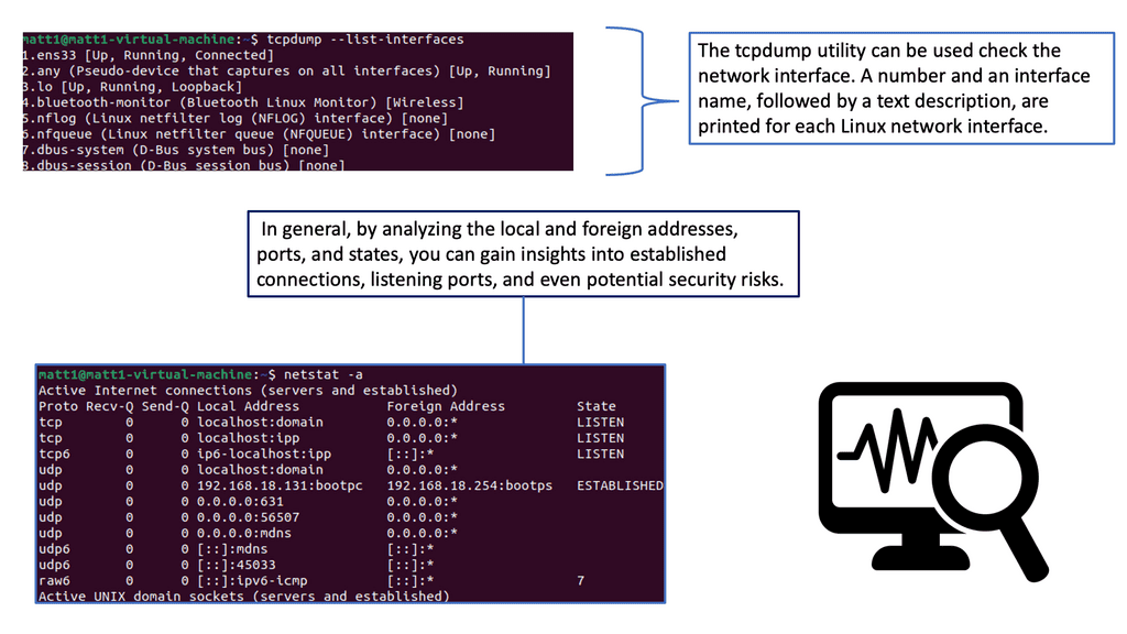
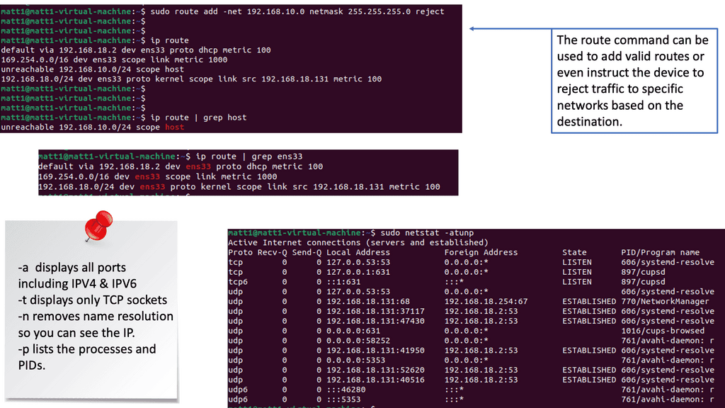
One of the fundamental features of Netstat is its ability to display active connections. Using the appropriate flags, you can view the list of established connections, their local and remote IP addresses, ports, and the protocol being used. This information is invaluable for identifying suspicious or unauthorized connections.
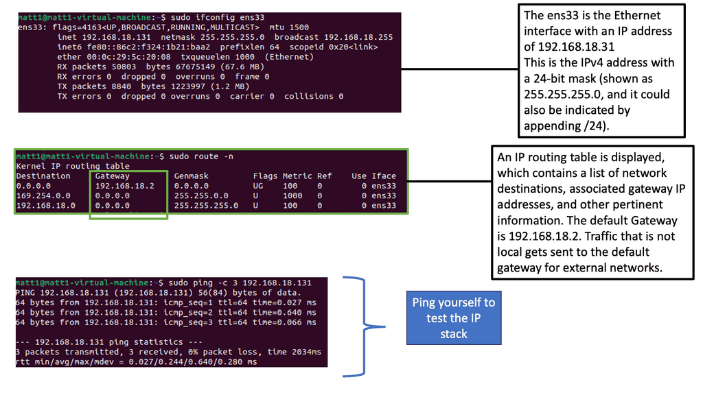
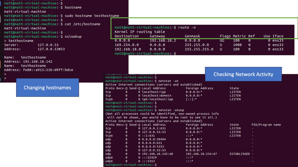
Get started by running the route command.
Analysis: Seem familiar? Yet another table with the following column headers:
Destination: This refers to the destination of traffic from this device. The default refers to anything not explicitly set.
Gateway: The next hop for traffic headed to the specific destination.
Genmask: The netmask of the destination.
Note: For more detailed explanations of all the columns and results, run
man route.
Run netstat to get a stream of information relating to network socket connections and UNIX domain sockets.
Note: UNIX domain sockets are a mechanism that allows processes local to the devices to exchange data.
To clean this up, you can view just the network traffic using.
netstat -at.-adisplays all ports, including IPV4 & IPV6-tdisplays only TCP sockets
Analysis: When routes are created in different ways, they display differently. In the most recent rule, you can see that no metric is listed, and the scope is different from the other automatic routes. That is the kind of information we can use for detection.
The route table will send traffic to the designated gateway regardless of the route’s validity. Threat actors can use this to intercept traffic destined for another location, making it a crucial place to look for indicators of compromise.
How Routing Tables Work:
Routing tables utilize various routing protocols, such as OSPF (Open Shortest Path First) or BGP (Border Gateway Protocol), to gather information about network topology and make informed decisions about the best paths for data packets. These protocols exchange routing information between routers, ensuring that each device has an up-to-date understanding of the network’s structure.
Routing Table Entries and Metrics:
Each entry in a routing table contains specific metrics that determine the best path for forwarding packets. Metrics can include hop count, bandwidth, delay, or reliability. By evaluating these metrics, routers can select the most optimal route based on network conditions and requirements.