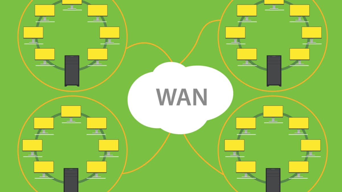
At its most straightforward, a data center is a physical facility that houses applications and data. Such a design is based on a computing and storage resources network that enables the delivery of shared applications and data. The critical elements of a data center design include routers, switches, firewalls, storage systems, servers, and application-delivery controllers.
The data center should be flexible in quickly deploying and supporting new services. Such a design needs substantial initial planning and consideration of port density, access layer uplink bandwidth, actual server capacity, and oversubscription, to name a few.
Key Design Considerations
**Network Architecture: The Foundation of Your Data Center**
The network architecture of a data center is the blueprint that determines how data flows through the system. It encompasses various topological designs, such as the traditional three-tier architecture and the more modern leaf-spine architecture. Each design comes with its unique set of advantages and trade-offs. When deciding on a network architecture, consider factors such as scalability, latency, and redundancy. A well-planned architecture can significantly enhance performance and future-proof your data center against the evolving demands of technology.
**Scalability: Planning for Growth**
A critical factor in data center topology design is scalability. As businesses grow, so do their data processing needs. Designing a topology that can easily accommodate additional resources without significant overhauls is crucial. Scalability considerations include modular designs that allow for the seamless addition of new servers and storage units, as well as network configurations that can handle increased traffic without bottlenecks. Investing in scalable solutions today can save significant time and resources in the future.
**Redundancy and Reliability: Ensuring Uptime**
In any data center, ensuring maximum uptime is paramount. Redundancy and reliability are key considerations in topology design to prevent downtime and data loss. This involves implementing redundant pathways for data, backup power supplies, and failover mechanisms to ensure continuous operation even in the event of hardware failures or power outages. By prioritizing reliability in your design considerations, you can safeguard your data center against unforeseen disruptions and maintain business continuity.
**Energy Efficiency: Balancing Performance and Sustainability**
With growing concerns about energy consumption and environmental impact, designing an energy-efficient data center is more important than ever. Considerations include the use of energy-efficient hardware, optimized cooling systems, and smart power management techniques. Efficient design not only reduces operational costs but also minimizes the environmental footprint of your data center. Striking the right balance between performance and sustainability is critical for long-term success.
Key Topology Considerations:
**Understanding Traditional Topologies**
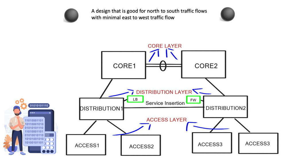
Before diving into the leaf and spine architecture, it’s essential to understand the limitations of traditional data center topologies. Historically, data centers used a three-tier architecture consisting of core, aggregation, and access layers. While effective at the time, this model struggles to keep up with the demands of modern applications due to its limited scalability and potential for bottlenecks. As data center needs evolved, so too did the need for a more robust and scalable topology.
**The Rise of Leaf and Spine Architecture**
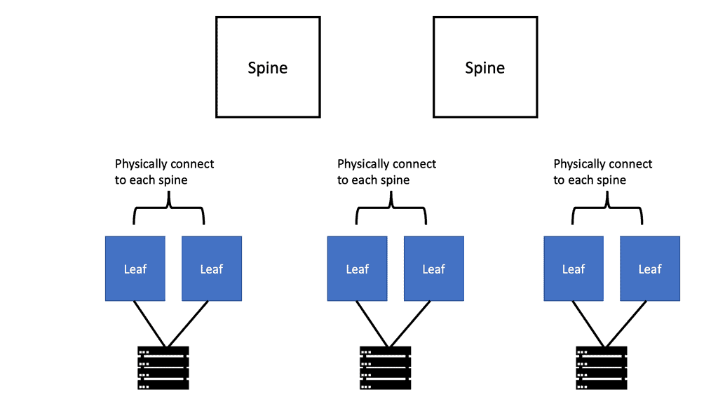
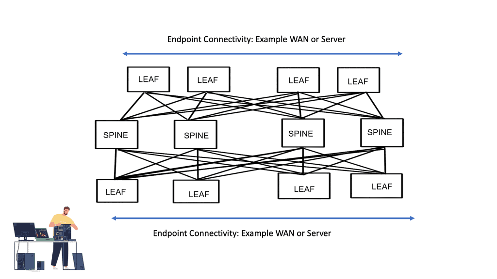
Leaf and spine architecture addresses the limitations of traditional topologies by providing a more scalable and efficient solution. In this model, every leaf switch is connected to every spine switch, creating a non-blocking network fabric. This design ensures that data traffic can be routed with minimal latency and congestion, regardless of the source or destination. The uniformity and predictability of this architecture make it an attractive option for organizations looking to future-proof their data centers.
**Advantages of Leaf and Spine Topologies**
One of the primary benefits of leaf and spine architecture is its scalability. As data center demands grow, additional spine switches can be added without disrupting the existing network, allowing for seamless expansion. Additionally, this topology provides consistent performance by evenly distributing data loads across all available paths. The redundancy inherent in leaf and spine designs also enhances network reliability, minimizing the risk of downtime and ensuring uninterrupted service delivery.
**Implementing Leaf and Spine in Modern Data Centers**
Adopting a leaf and spine topology requires careful planning and execution. Organizations must assess their current infrastructure, consider future growth projections, and select the appropriate switches and cabling to support the architecture. While the initial investment may be higher than that of traditional models, the long-term benefits of scalability, performance, and reliability make it a worthwhile endeavor for businesses aiming to stay competitive in the digital landscape.
Traditional Tree-Based Topologies
We have tree-based topologies on the opposite side of a spine-leaf switch design. Tree-based topologies have been the mainstay of data center networks. Traditionally, Cisco has recommended a multi-tier tree-based data center topology, as depicted in the diagram below.
These networks are characterized by aggregation pairs ( AGGs ) that aggregate through many network points. Hosts connect to access or edge switches, which connect to distribution, and distribution connects to the core.
The core should offer no services ( firewall, load balancing, or WAAS ), and its central role is to forward packets as quickly as possible. The aggregation switches define the boundary for the Layer 2 domain, and to contain broadcast traffic to individual domains, VLANs are used to further subdivide traffic into segmented groups. This style of design operates very differently from spine-leaf architecture.
Guide: Leaf and Spine with Cisco ACI
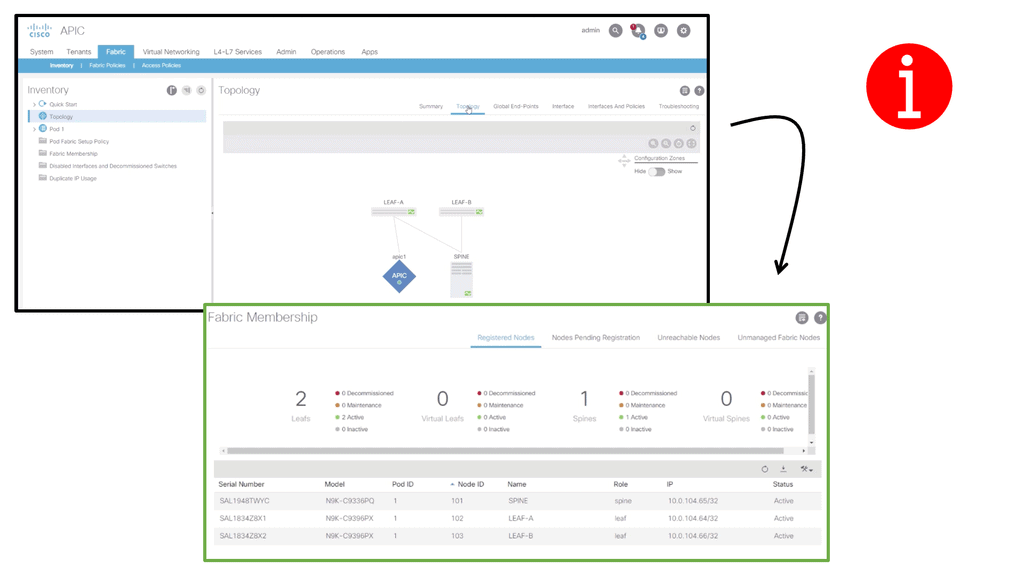
The following lab guide addresses the leaf and spine with Cisco ACI. The screenshot below shows a small topology that is fine for demonstration purposes. The leaf and spine are based on the Cisco Nexus 9000 series. The ACI has an automated fabric discovery process, and as you can see, we have successfully registered all fabric members.
The traditional three-tier model was based on the following design principles:
- The access switch connects to endpoints, e.g., servers.
- The aggregation or distribution switches provide redundant connections to access switches.
- The core switches provide fast transport between aggregation switches, typically connected in a redundant pair for high availability.
- Networking and security services such as load balancing or firewalling were typically connected to the distribution layers.
The focus of the design
Their design’s focus was based on fault avoidance principles, and the strategy for implementing this principle is to take each switch and its connected links and build redundancy into it. This led to the introduction of port channels and devices deployed in pairs. In addition, servers pointed to a First Hop Redundancy Protocol, like HSRP or VRRP ( Hot Standby Router Protocol or Virtual Router Redundancy Protocol ). Unfortunately, the steady-state type of network design led to many inefficiencies:
- Inefficient use of bandwidth via a single-rooted core.
- Operational and configuration complexity.
- The cost of having redundant hardware.
- It is not optimized for small flows.
Recent changes to application and user requirements have changed the functions of data centers, which in turn has altered the topology and design of the data center to a spine-leaf switch topology. For example, the traditional aggregation point design style was inefficient, and recent changes in end-user requirements are driving architects to design around the following key elements.
Spine Leaf Architecture: Requirements
A spine-leaf architecture collapses one of these tiers at the most basic level, as depicted in the diagram below. Follow the following design principles:
- The removal of the Spanning Tree Protocol (STP)
- Increased use of fixed-port switches over modular models for the network backbone
- More cabling to purchase and manage, given the higher interconnection count
- A scale-out vs. scale-up of infrastructure.
Leaf and Spine Main Points
With the introduction of the cloud and containerized infrastructure, there was an increase in east-west traffic. East-west traffic differs from north to south traffic and moves laterally from server to server. Generally, this type of traffic flow stays internal to the data center.
With the change in traffic patterns, we must design our data centers to have low latency and optimized traffic flows, especially for time-sensitive or data-intensive applications. A spine-leaf data center design aids this by ensuring traffic always has the same number of hops from its next destination, so latency is lower and predictable.
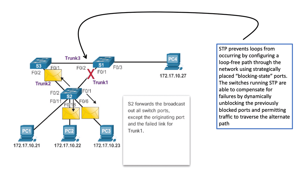
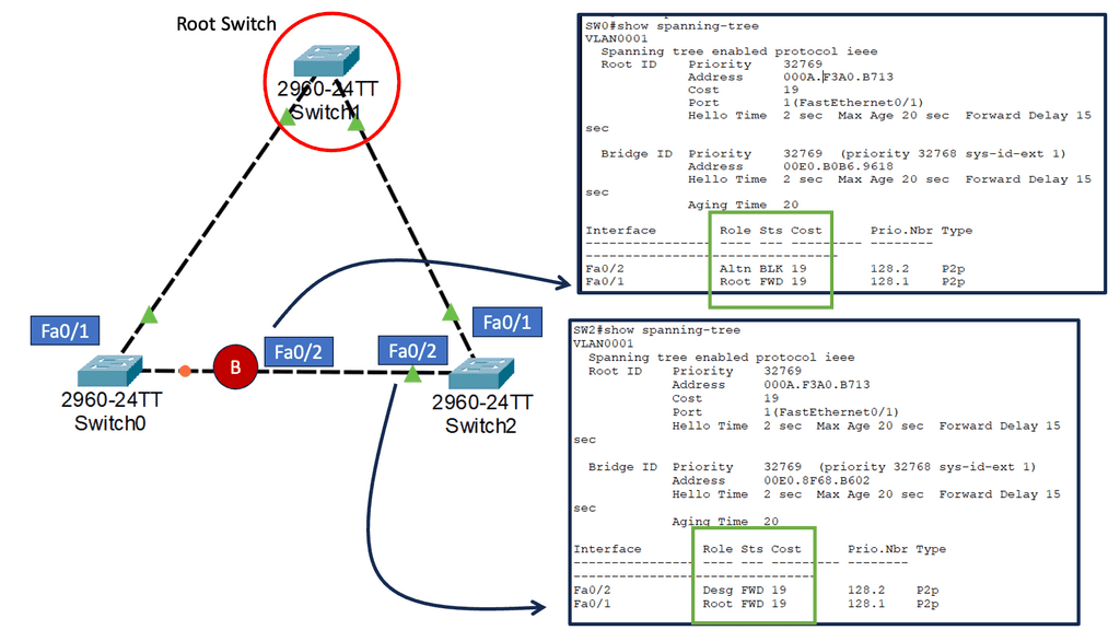
STP has always been problematic in the data center. Now, the capacity improves with a leaf and spine because STP is no longer required. In the past, STP blocked redundant paths between two switches, where only one could be active at any time.
As a result, paths often need to be more subscribed. With a leaf, spine-leaf architectures rely on protocols such as Equal-Cost Multipath (ECPM) routing to load balance traffic across all available paths while still preventing network loops. So, instead of running STP to the spine layer, we can run routing protocols.
We also have better scalability. We can add additional spine switches, and leaf switches can be seamlessly inserted when port density becomes problematic. There is no need to take down the core layer for upgrades.
Data Center Requirements
- 1) Equidistant endpoints with non-blocking network core.
Equidistant endpoints mean that every device is a maximum of one hop away from the other, resulting in consistent latency in the data center. The term “non-blocking” refers to the internal forwarding performance of the switch.
Non-blocking is the ability to forward at line rate tx/Rx – sender X can send to receiver Y and not be blocked by a simultaneous sender. A blocking architecture cannot deliver the total bandwidth even if the individually switching modules are not oversubscribed or if all ports are not transmitting simultaneously.
- 2) Unlimited workload placement and mobility.
The application team wants to place the application at any point in the network and communicate with existing services like storage. This usually means that VLANs need to sprawl for VMotion to work. The main question is, where do we need large layer 2 domains? Bridging doesn’t scale, and that’s not just because of spanning tree issues; it’s because the MAC addresses are not hierarchical and cannot be summarized. There is also a limit of 4000 VLANs.
- 3) Lossless transport for storage and other elephant flows.
To support this type of traffic, data centers require not only conventional QoS tools but also Data Center Bridging ( DCB ) tools such as Priority flow control ( PFC ), Enhanced transmission selection ( ETS ), and Data Center Bridging Exchange ( DCBX ) to be applied throughout their designs. These standards are enhancements that allow lossless transport and congestion notification over full-duplex 10 Gigabit Ethernet networks.
Feature | Benefit |
Priority-based Flow Control ( PFC ) | Manages bursty single traffic source on a multiprotocol link |
Enhanced transmission selection ( ETS ) | Enables bandwidth management between traffic types for multiprotocol links |
Congestion notification | Addresses the problems of sustained congestion by moving corrective action to the edge of the network |
Data Center Bridging Exchange Protocol | Allows the exchange of enhanced Ethernet parameters |
- 4) Simplified provisioning and management.
Simplified provisioning and management are critical to operational efficiency. However, the ability to auto-provision and for the users to manage their networks is challenging for future networks.
- 5) High server-to-access layer transmission rate at Gigabit and 10 Gigabit Ethernet.
Before the advent of virtualization, servers transitioned from 100Mbps to 1GbE as processor performance increased. With the introduction of high-performance multicore processors and each physical server hosting multiple VMs, the processor-to-network connection bandwidth requirements increased dramatically, making 10 Gigabit Ethernet the most common network access option for servers.
In addition, the popularization of 10 Gigabit Ethernet for server access has provided a straightforward approach to group/bundle multiple Gigabit Ethernet interfaces into a single connection, making Ethernet an extremely viable technology for future-proof I/O consolidation.
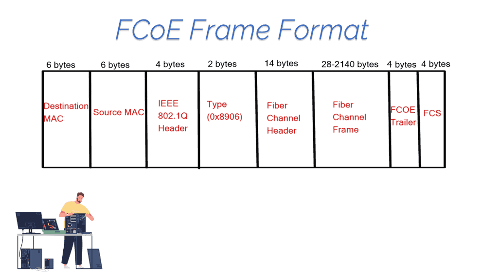
In addition, to reduce networking costs, data centers are now carrying data and storage traffic over Ethernet using protocols such as iSCSI ( Internet Small Computer System Interface ) and FCoE ( Fibre Channel over Ethernet ). FCoE allows the transport of Fibre channels over a lossless Ethernet network.
Although there has been some talk of introducing 25 Gigabit Ethernet due to the excessive price of 40 Gigabit Ethernet, the two main speeds on the market are Gigabit and 10 Gigabit Ethernet. The following is a comparison table between Gigabit and 10 Gigabit Ethernet:
Gigabit Ethernet | 10 Gigabit Ethernet |
+ Well know and field-tested | + Much faster vMotion |
+ Standard and cheap Copper cabling | + Converged storage & network ( FCoE or lossless iSCSI/NFS) |
+ NIC on the motherboard | + Reduce the number of NICs per server |
+ Cedric Kelly | + Built-in Qos with ETS and PFC |
+ Uses fiber cabling which has lower energy consumption and error rate | |
– Numerous NICs per hypervisor host. Maybe up to 6 NICs ( user data, VMotion, storage ) | – More expensive NIC cards |
– No storage/networking convergence. Unable to combine networking and storage onto one NIC | – Usually requires new cabling to be laid which intern could mean more structured panels |
– No lossless transport for storage and elephant flows | – SFP used either for single-mode or multimode fiber can be up to $4000 list per each |
Spine-Leaf Switch Design
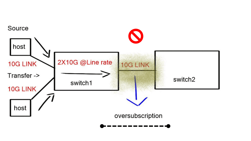
The critical difference between traditional aggregation layers/points and fabric networks is that fabric doesn’t aggregate. If we want to provide 10GB for every edge router to send 10GB to every other edge router, we must add bandwidth between routers A and B, i.e., if we have three hosts sending at 10GB each, we need a core that supports 30 GB.
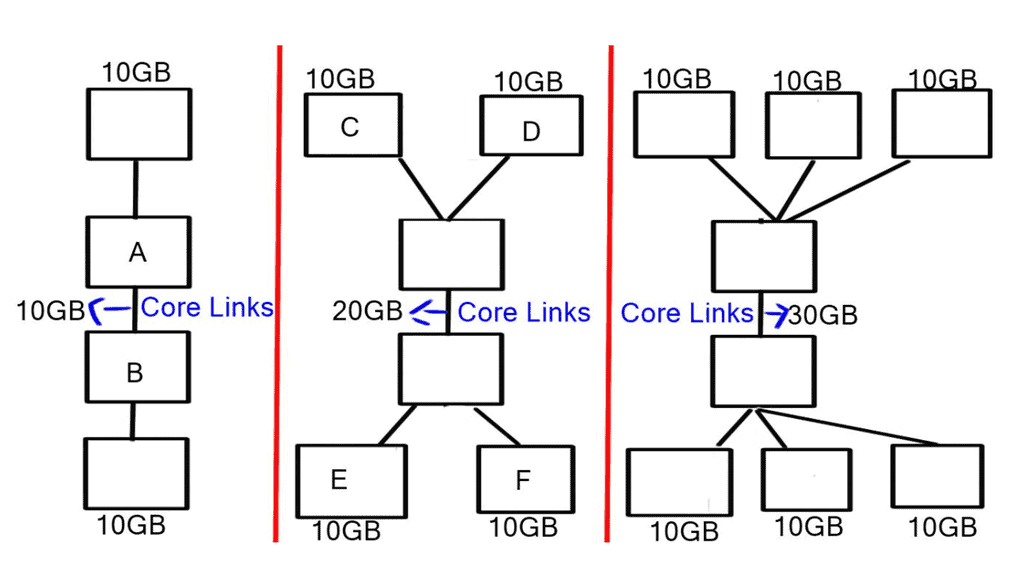
We must add bandwidth at the core because what if two routers wanted to send 2 x 10GB of data, and the core only supports a maximum of 10GB ( 10GB link between routers A and B)? Both data streams must be interleaved onto the oversubscribed link so that both senders get equal bandwidth.
You get blocked and oversubscribed when more bandwidth comes into the core than the core can accommodate. Blocking and oversubscription cause delay and jitter, which is bad for some applications, so we must find a way to provide total bandwidth between each end host.
Oversubscription is expressed as the ratio of inputs to outputs (ex. 3:1) or as a percent that is calculated (1 – (# outputs / # inputs)). For example, (1 – (1 output / 3 inputs)) = 67% oversubscribed). There will always be some oversubscription on the network, and there is nothing we can do to get away from that, but as a general rule of thumb, an oversubscription value of 3:1 is best practice.
Some applications will operate fine when oversubscription occurs. It is up to the architect to thoroughly understand application traffic patterns, bursting needs, and baseline states to define the oversubscription limits a system can tolerate accurately.
The simplest solution to overcome the oversubscription and blocking problems would be to increase the bandwidth between Router A and B, as shown in the diagram labeled “Traditional Aggregation Topology.” This is feasible up to a certain point. Router A and B links must also grow to 10GB and 30 GB when the number of edge hosts grows. Datacenter links and the optics used to connect them are expensive.
Spine-Leaf Switch Design
The solution is to divide the core devices into several spine devices, which expose the internal fabric, enabling a spine-leaf architecture similar to what you see with ACI networks. This is achieved by spreading the fabric across multiple devices ( leaf and spine ).
The spreading of the fabric results in every leaf edge switch connecting to every spine core switch, resulting in every edge device having the total bandwidth of the fabric. This places multiple traffic streams parallel, unlike the traditional multitier design that stacks multiple streams onto a single link.
In addition, the higher degree of equal-cost multi-path routing ( ECMP ) found with leaf and spine architectures allows for greater cross-sectional bandwidth between layers, thus greater east-west bandwidth. There is also a reduction in the fault domain compared to traditional access, distribution, and core designs.
A failure of a single device only reduces the available bandwidth by a fraction, and only transit traffic will be lost with a link failure. ECMP reduces liability to a single fault and brings domain optimization.
**Origination of the spine and leaf design**
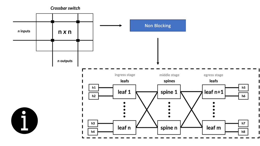
Charles Clos initially designed a Clos network in 1952 as a multi-stage circuit-switched interconnection network to provide a scalable approach to building large-scale voice switches. It constrained high-speed switching fabrics and required low-latency, non-blocking switching elements.
There has been an increase in the deployment of Clos-based models in data center deployments. Usually, the Clos network is folded around the middle to form a “folded-Clos” network, referred to as a spine-leaf architecture. The spine-leaf switch design consists of three switches:
- Servers connect directly to ToR ( top of rack ) switches.
- ToR connects to aggregation switches.
- Intermediate switches connect to aggregation switches.
The spine is responsible for interconnecting all Leafs and allows hosts in one rack to talk to hosts in another. The leaves are responsible for physically connecting the servers and distributing traffic via ECMP across all spine nodes.
Leaf and Spine: Folded 3-Stage Clos fabric
Spine-leaf switch deployment considerations:
A. Spine-leaf switch: Fixed or modular switches
Fixed Switches | Modular switches |
+ Cheaper | + Gradual Growth |
+ Lower Power Consumption | + Larger fabrics with leaf/spine topologies |
+ Require less space | + Build-in redundancy with redundant SUPs and SSO/NSF |
+ More ports per RU | + In-Service software redundancy |
+ Easier to manage | |
– Hard to manage | – More expensive |
– Difficult to expand | |
– More cabling due to an increase in device numbers |
The leaf layer determines the size of the spine and the oversubscription ratios. It is responsible for advertising subnets into the network fabric. An example of a leaf device would be a Nexus 3064, which provides the following:
- Line rate for Layer 2 and Layer 3 on all ports.
- Shared memory buffer space.
- Throughput of 1/2 terabits per second ( Tbps ) and 950 million packets per second ( Mpps )
- 64-way ECMP
The spine layer is responsible for learning infrastructure routes and physically interconnecting all leaf nodes. The Nexus 7K is the platform for the Spine device layer. The F2 series line cards can provide 48x 10G line rate ports and fit the requirements for spine architecture very well.
The following are the types of implementations you could have with this topology:
- Layer 3 fabric with standard routing.
- Large-scale bridging ( FabricPath, THRILL, or SPB ).
- Many-chassis MLAG ( Cisco VSS ).
This article will focus on Layer 3 fabrics with standard routing.
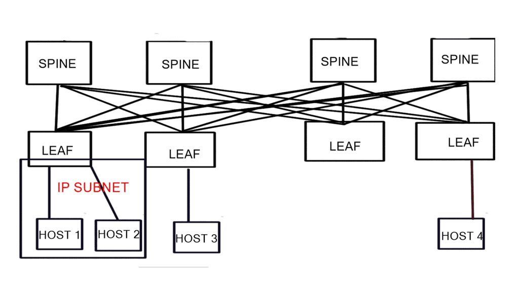
B. Spine-leaf switch: Non-redundant layer 3 design
 **Spine-leaf switch: Design Summary**
- Layer 3 directly to the access layer. Layer 2 VLANs do not span the spine layer.
- Servers are connected to single switches. Servers are not dual connected to two switches, i.e., there is no server to switch redundancy or MLAG.
- All connections between the switches will be pure routed point-to-point layer 3 links.
- There are no inter-switch VLANs, so no VLAN will ever go beyond one switch.
When the spine switches only advertise the default to the leaf switches, the leaf switches lose visibility of the entire network, and you will need additional intra-spine links. Therefore, intra-spine links should not be used for data plane traffic in a leaf-spine architecture.
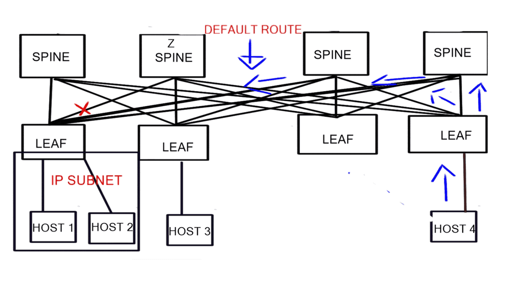
**Spine-leaf switch: Design assumptions**
The spine layer passes a default route to the Leaf. The link between the Leaf connecting to Host 1 and Spine Z fails. In the diagram, the link is marked with a red “X.” Host 4 sends traffic to the fabric destined for Host 1.
This traffic spreads ( ECMP ) across all links connecting the connected Leaf to the Spine layers. The traffic hits Spine C, and as C does not have a direct link ( it has failed ) to the Leaf connecting to Host 1, some traffic may be dropped while others will be sub-optimal. To overcome this, you must add inter-switch links between the Spine layers, which is not recommended.
Spine-leaf switch: Recommendations
- Buy Leaf switches that can support enough IP prefixes and don’t use summarization from Spine to Leaf.
- Always use 40G links instead of channels of 4 x 10G links because link aggregation bandwidth does not affect routing costs. If you lose a link in the port channel, the cost of the port channel does not change, which could result in congestion on the link.
- You could use Embedded Event Manager ( EEM ) scripting to change the OSPF cost after one of the port channels fails. This would add complexity to the network as you now don’t have equal-cost routes. This would lead you to use the Cisco proprietary protocol EIGRP, which supports unequal cost routing. If you didn’t want to support a Cisco proprietary protocol, you could implement MPLS TE between the ToR switches. First, you need to check that the DC switches support the MPLS switching of labels.
- Use QSFP optics as they are more robust than SFP optics. This will lower the likelihood of one of the parallel links failing.
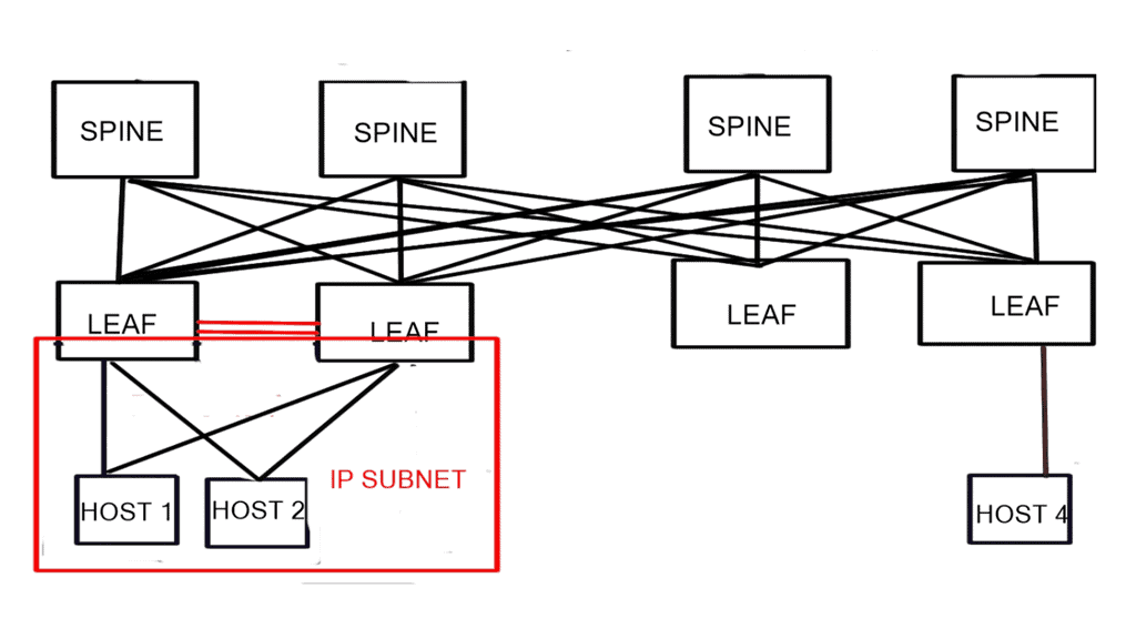
C. Spine-leaf switch: Redundant layer 3 design
Spine-leaf switch: Design Summary
- The servers are dual home to two different switches.
- Servers have one IP address due to the restriction of TCP applications. Ideally, use LACP ( Link Aggregation Control Protocol ) between the host and servers.
- Layer 2 trunk links between the Leaf switches are needed to carry VLANs that span both switches. This will restrict VLANs from spanning the core, thus creating a sizeable L2 fabric based on STP.
- ToR switches must be in the same subnets ( share the server’s subnet) and advertise this subnet into the fabric. Again, the servers are dual-homed to 2 switches with one IP address.
Spine-leaf switch: The challenges
The leaf switches both advertise the same subnet to the spine switches. The spine switches and thinks they have two paths to reach the host. The Spine switch will spread its traffic from Host 1 to Leaf switches connecting Host 1 and Host 2. In specific scenarios, this could result in traffic to the hosts traversing the Interswitch link between the leaf nodes.
This may not be a problem if most traffic leaves the servers northbound ( traffic leaving the data center ). However, if there is a lot of inbound traffic, this link could become a bottleneck and congestion point. This may not be an issue if this is a hosting web server farm because most traffic will leave the data center to external users.
Spine-leaf switch: Recommendation
- If there is a lot of east-to-west traffic ( 80 % ), using LAG ( Link Aggregation Group ) between the servers and ToR Leaf switches is mandatory.
- The two Leaf switches must support MLAG ( Multichassis Link Aggregation ). The result of using MLAG on the Leaf switches is that when connecting Leaf receives traffic destined for host X, it knows it can reach it directly through its connected link—resulting in optimal southbound traffic flow.
- Most LAG solutions place traffic generated from a single TCP session onto a single uplink, limiting the TCP session throughput to the bandwidth of a single uplink interface. However, Dynamic NIC teaming is available in Windows Server 2012 R2 which can split a single TCP session into multiple flows and distribute them across all uplinks.
- Use dynamic link aggregation – LACP and not static port channels. The LAGs between servers and switches should use LACP to prevent traffic blackholing.
 | Main Checklist Points To Consider
|
Recap on Spine and Leaf Architecture
Spine Switches:
Spine switches form the backbone of the network in a Spine Leaf architecture. They are high-performance switches that connect to every leaf switch in the network. The spine switches provide a non-blocking, high-bandwidth fabric for data transfer between leaf switches. They ensure data traffic flows seamlessly across the network, avoiding bottlenecks and congestion.
Leaf Switches:
Leaf switches are connected to the spine switches and act as the access layer in a Spine Leaf architecture. They connect end-user devices, servers, or other network devices to the spine switches. Leaf switches are responsible for forwarding traffic between devices within the same leaf and between different leaf switches. They offer a high degree of network flexibility and redundancy.
Benefits of Spine Leaf Architecture:
1. Scalability: Spine Leaf architecture allows for easy scalability as new leaf switches can be added without affecting the existing network. This scalability makes it ideal for growing businesses and organizations with expanding network requirements.
2. High Bandwidth: The architecture provides high bandwidth capacity by leveraging multiple spine switches. This efficiently handles heavy data traffic and ensures optimal network performance even during peak usage.
3. Low Latency: Spine Leaf architecture minimizes latency by eliminating multiple layers of network hierarchy. With fewer hops and shorter paths, data packets can be transmitted quickly, improving application response times.
4. Redundancy and Resilience: The architecture offers built-in redundancy and resilience. If a link or a switch fails, traffic can be automatically rerouted through alternate paths, ensuring uninterrupted network connectivity and minimizing downtime.
5. Enhanced Performance: Spine Leaf architecture improves overall network performance by evenly distributing traffic across multiple paths. This load-balancing capability optimizes resource utilization and prevents any single point of failure.
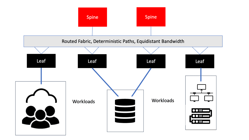
The spine-leaf architecture has only two layers of switches: spines and leaves. Switches form the spine layer, which performs routing and works as the network’s core. Access switches connect servers, storage devices, and other end users to the leaf layer. A data center network with this structure has a lower hop count and a lower network latency. Leaf switches are connected to spine switches in the spine-leaf architecture. In this design, there is only one interconnected switch path between any leaf switches so that any server can communicate with any other server.
Why Use Spine-leaf Architecture?
The spine-leaf architecture has become a famous data center architecture, bringing many advantages, including scalability and network performance. In five points, we summarize the benefits of spine-leaf architecture in modern networks.
– Enhanced redundancy: The spine-leaf architecture connects the servers with the core network, providing greater flexibility in hyperscale data centers. As a result, the leaf switch can serve as a bridge between the server and the core network. A sizeable non-blocking fabric is formed by connecting leaf switches to spine switches, increasing redundancy and reducing traffic bottlenecks.
– Enhanced bandwidth: The spine-leaf architecture can effectively avoid traffic congestion through protocols such as transparent interconnection of multiple links (TRILL) and shortest path bridging (SPB). Adding uplinks to the spine switch increases interlayer bandwidth and reduces oversubscription to secure network stability using the spine-leaf architecture.
– Enhanced scalability: Multiple links carry traffic in the spine-leaf architecture. In addition to improving scalability, switches can help enterprises expand their businesses in the future.
– Reduced expenses: Because spine-leaf architecture allows switches to handle more connections, data centers deploy fewer devices. A spine-leaf architecture minimizes costs in many data center networks.
– Increased Performance: With a maximum number of hops of only two, we facilitate a more direct traffic path, enhancing overall performance and reducing bottlenecks. This applies only when the destination is on the same leaf switch.
Spine and Leaf Popularity
Because of cloud computing and containerized infrastructure, east-west traffic increases in modern data centers. East-west traffic moves from server to server in a lateral fashion. Modern applications have components distributed across multiple servers or virtual machines, which partly explains this shift. When it comes to east-west traffic, low-latency, optimized flows are critical for applications that are time-sensitive or data-intensive. Spine-leaf architectures reduce latency by ensuring every hop between destinations is the same.
STP has also been removed, increasing capacity. Only one switch can be active simultaneously, even though STP can provide redundant paths between two switches. Consequently, paths are oversubscribed. Spine-leaf architectures use protocols such as Equal-Cost Multipath (ECMP) to accomplish load-balancing traffic across all available paths across all available paths. Topologies with spines and leaves improve scalability and performance. Capacity can be increased by adding additional spine switches and connecting them to each leaf. Likewise, new leaf switches can be seamlessly inserted if port density becomes an issue. “Scaling out” infrastructure doesn’t change anything.
Charles Clos – large-scale switching fabrics
Using Edson Erwin’s concept of building large-scale switching fabrics for telephone systems, Charles Clos (pronounced Klo) developed the Clos network, published in the Bell System Technical Journal in 1953. The original paper, “A Study of Non-Blocking Switching Networks,” is cited in hundreds of subsequent documents. In telephony systems, a Clos network consists of three stages, each with several crossbar switches. To reduce complexity and cost, stages were introduced instead of a single prominent crossbar to reduce the number of crosspoint interconnections needed to build large-scale crossbar-like functionality.
Crossbar switches are strictly non-blocking switches with n inputs and n outputs and interconnecting lines connecting inputs and outputs. For idle input and output lines, non-blocking means that connections can be made without interrupting other connected lines. A crossbar is fundamentally designed to accomplish this. In this case, the complexity of the crossbar switch is O(n2).
Data center topology
A spine-leaf architecture is a variation of data center topologies that consists of two switching layers. We have a spine-leaf switch design consisting of two layers. The leaf layer consists of access switches that aggregate traffic from endpoints that could be traditional servers or containers and connect directly to the spine, which is the network core. The Spine switch will often have two for redundancy to interconnect all leaf switches in a full-mesh leaf and spine topology. With a spine and leaf data center network design, the leaf switches do not directly connect.
The underlay and the overlay
eBGP, in this case, is used to exchange routing information between the nodes of the fabric through the underlay, which provides point-to-point Layer 3 interfaces between leafs and spines. Using eBGP to advertise the loopback addresses of VTEPs in the fabric (typically leaves), the underlay offers connectivity between the loopbacks.
In the overlay layer, packets are encapsulated in an outer IP header and transported from one VTEP to another using the data plane encapsulation layer. Source IP addresses are the loopbacks of the originating VTEPs, and destination IP addresses are the loopbacks of the terminating VTEPs.
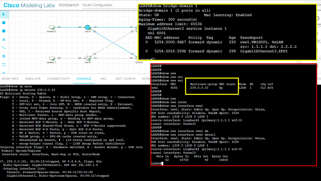
Example: Cisco ACI
Instead, all connectivity goes through the core, and the physical and logical layout is generally the same based on network overlay protocols, more than likely VXLAN. An example of a data center that utilizes such a design is the Cisco ACI. The ACI Cisco consists of three main components: the Application Policy Infrastructure Controller (APIC), the spine switches, and the leaf switches.

- DMVPN - May 20, 2023
- Computer Networking: Building a Strong Foundation for Success - April 7, 2023
- eBOOK – SASE Capabilities - April 6, 2023