
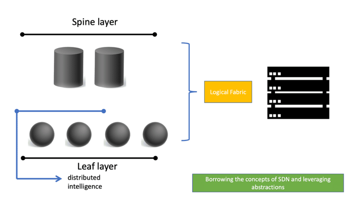
ACI Main Components
-APIC controllers and underlay network infrastructure are the main components of ACI. Due to specialized forwarding chips, hardware-based underlay switching in ACI has a significant advantage over software-only solutions.
-As a result of Cisco’s own ASIC development, ACI has many advanced features, including security policy enforcement, microsegmentation, dynamic policy-based redirection (allowing external L4-L7 service devices to be inserted into the data path), and detailed flow analytics—in addition to performance and flexibility.
-ACI underlays require Nexus 9000 switches exclusively. There are Nexus 9500 modular switches and Nexus 9300 fixed 1U to 2U models available. The spine function in ACI fabric is handled by certain models and line cards, while leaves can be handled by others, and some can even be used for both functions at the same time.The combination of different leaf switches within the same fabric is not limited.
ACI Networks
ACI Networks refers to the full architecture, fabric, and operational model behind Cisco Application Centric Infrastructure (ACI) — Cisco’s flagship SDN solution for modern data centers. ACI Networks combine policy‑driven automation, spine‑leaf switching, VXLAN overlays, centralized control, and application‑aware segmentation to create a programmable, scalable, and secure data‑center fabric.
This section continues your sequence perfectly (SD‑WAN → SASE → Security → Visibility → ACI).
What ACI Networks Are
ACI Networks are built on three pillars:
Policy Model — EPGs, contracts, tenants, and application profiles define intent.
Fabric Architecture — Spine‑leaf topology with VXLAN and distributed anycast gateways.
Centralized Control — APIC manages policies, fabric health, and automation.
ACI Networks replace manual configuration with intent‑based networking, where the network automatically aligns with application requirements.
ACI Network Architecture
An ACI Network consists of:
Leaf switches — where endpoints connect
Spine switches — high‑speed fabric backbone
APIC controllers — policy, automation, and fabric management
VXLAN overlays — scalable, multi‑tenant segmentation
Anycast gateways — distributed L3 gateways for optimal routing
This creates a high‑performance, low‑latency, horizontally scalable data‑center fabric.
ACI Network Components
Endpoint Groups (EPGs) — Logical groupings of workloads
Contracts — Define allowed communication between EPGs
Tenants — Multi‑domain isolation
Bridge Domains — L2 forwarding scopes
Application Profiles — Map app tiers to policies
Fabric Policies — Interface, routing, and access policies
These components form the foundation of ACI’s intent‑based model.
Security in ACI Networks
ACI Networks provide strong security through:
microsegmentation
EPG‑based isolation
contract‑based Zero Trust
identity‑aware endpoint classification
policy‑driven enforcement
Security becomes application‑centric, not IP‑centric.
ACI Network Visibility
Visibility is delivered through:
Nexus Dashboard Insights
Telemetry & health scores
Flow analytics
Endpoint tracking
This allows operators to detect drift, anomalies, misconfigurations, and performance issues across the fabric.
ACI Networks in Hybrid Cloud
ACI extends into cloud environments:
AWS
Azure
GCP
Using Cloud ACI, policies follow workloads across on‑prem and cloud, creating a unified segmentation and security model.
Outcome
ACI Networks deliver:
policy‑driven automation
scalable spine‑leaf architecture
secure segmentation
consistent hybrid‑cloud policies
deep visibility and assurance
application‑centric networking
ACI becomes the core SDN fabric for modern enterprise data centers.
Cisco Data Center Design
**The rise of virtualization**
Virtualization is creating a virtual — rather than actual — version of something, such as an operating system (OS), a server, a storage device, or network resources. Virtualization uses software that simulates hardware functionality to create a virtual system.
It is creating a virtual version of something like computer hardware. It was initially developed during the mainframe era. With virtualization, the virtual machine could exist on any host. As a result, Layer 2 had to be extended to every switch.
This was problematic for Larger networks as the core switch had to learn every MAC address for every flow that traversed it. To overcome this and take advantage of the convergence and stability of layer 3 networks, overlay networks became the choice for data center networking, along with introducing control plane technologies such as EVPM MPLS.
**The Cisco Data Center Design Transition**
The Cisco data center design has gone through several stages. First, we started with the Spanning Tree, moved to the Spanning Tree with vPCs, and then replaced the Spanning Tree with FabricPath. FabricPath is what is known as a MAC-in-MAC Encapsulation.
Today, in the data center, VXLAN is the de facto overlay protocol for data center networking. The Cisco ACI uses an enhanced version of VXLAN to implement both Layer 2 and Layer 3 forwarding with a unified control plane. Replacing SpanningTree with VXLAN, where we have a MAC-in-IP encapsulation, was a welcomed milestone for data center networking.
**Overlay networking with VXLAN**
VXLAN is an encapsulation protocol that provides data center connectivity using tunneling to stretch Layer 2 connections over an underlying Layer 3 network. VXLAN is the most commonly used protocol in data centers to create a virtual overlay solution that sits on top of the physical network, enabling virtual networks. The VXLAN protocol supports the virtualization of the data center network while addressing the needs of multi-tenant data centers by providing the necessary segmentation on a large scale.
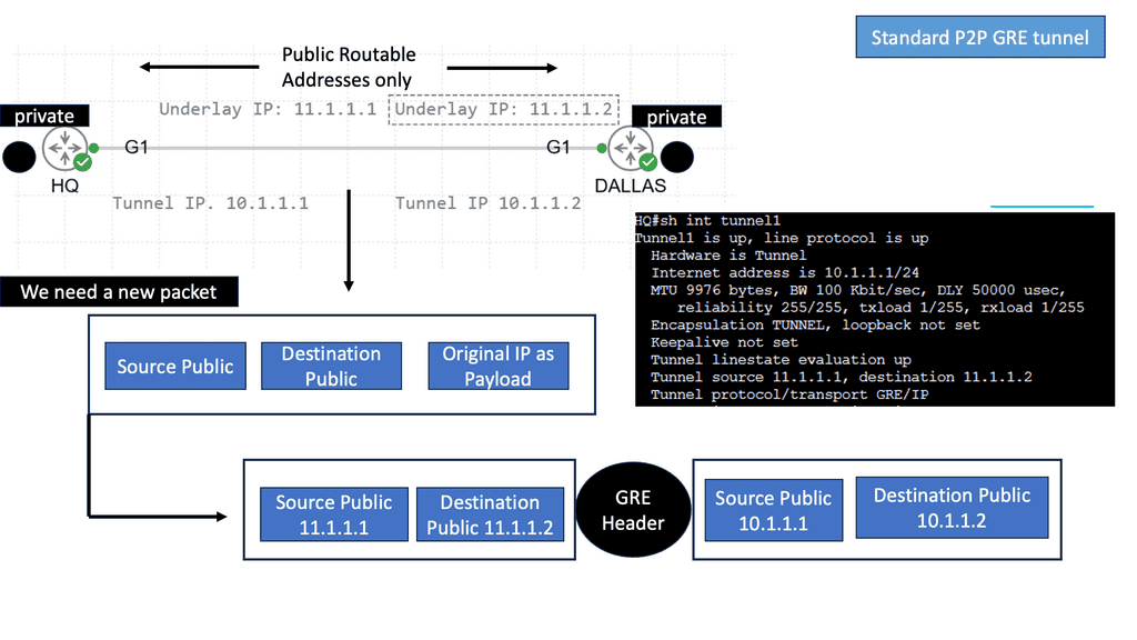
Here, we are encapsulating traffic into a VXLAN header and forwarding between VXLAN tunnel endpoints, known as the VTEPs. With overlay networking, we have the overlay and the underlaying concept. By encapsulating the traffic into the overlay VXLAN, we now use the underlay, which in the ACI is provided by IS-IS, to provide the Layer 3 stability and redundant paths using Equal Cost Multipathing (ECMP) along with the fast convergence of routing protocols.
Example: Point to Point GRE
 Cisco ACI Overview
Introduction to the ACI Networks
The base of the ACI network is the Cisco Application Centric Infrastructure Fabric (ACI)—the Cisco SDN solution for the data center. Cisco has taken a different approach from the centralized control plane SDN approach with other vendors and has created a scalable data center solution that can be extended to multiple on-premises, public, and private cloud locations.
The ACI networks have many components, including Cisco Nexus 9000 Series switches with the APIC Controller running in the spine leaf architecture ACI fabric mode. These components form the building blocks of the ACI, supporting a dynamic integrated physical and virtual infrastructure.
Enhanced Scalability and Flexibility:
One of the critical advantages of ACI networks is their ability to scale and adapt to changing business needs. Traditional networks often struggle to accommodate rapid growth or dynamic workloads, leading to performance bottlenecks. ACI networks, on the other hand, offer seamless scalability and flexibility, allowing businesses to quickly scale up or down as required without compromising performance or security.
Simplified Network Operations:
Gone are the days of manual network configurations and time-consuming troubleshooting. ACI networks introduce a centralized management approach, where policies and structures can be defined and automated across the entire network infrastructure. This simplifies network operations, reduces human errors, and enables IT teams to focus on strategic initiatives rather than mundane tasks.
Enhanced Security:
Network security is paramount in today’s threat landscape. ACI networks integrate security as a foundational element rather than an afterthought. With ACI’s microsegmentation capabilities, businesses can create granular security policies and isolate workloads, effectively containing potential threats and minimizing the impact of security breaches. This approach ensures that critical data and applications remain protected despite evolving cyber threats.
**Real-World Use Cases of ACI Networks**
- Data Centers and Cloud Environments:
ACI networks have revolutionized data center and cloud environments, enabling businesses to achieve unprecedented agility and efficiency. By providing a unified management platform, ACI networks simplify data center operations, enhance workload mobility, and optimize resource utilization. Furthermore, ACI’s seamless integration with cloud platforms ensures consistent network policies and security across hybrid and multi-cloud environments.
- Network Virtualization and Automation:
ACI networks are a game-changer for network virtualization and automation. By abstracting network functionality from physical hardware, ACI enables businesses to create virtual networks, provision services on-demand, and automate network operations. Streamlining network deployments accelerates service delivery, reduces costs, and improves overall performance.
Recap: Traditional Data Center
Firstly, the Cisco data center design traditionally built our networks based on hierarchical data center topologies. This is often referred to as the traditional data center, which has a three-tier structure with an access layer, an aggregation layer, and a core layer. Historically, this design enabled substantial predictability because aggregation switch blocks simplified the spanning-tree topology. In addition, the need for scalability often pushed this design into modularity with ACI networks and ACI Cisco, which increased predictability.
Recap: The Challenges
However, although we increased predictability, the main challenge inherent in the three-tier models is that they were difficult to scale. As the number of endpoints increases and the need to move between segments increases, we need to span layer 2. This is a significant difference between the traditional and the ACI data centers.
The Journey to ACI
Our journey towards ACI started in the early 1990s when we examined the most traditional and well-known two—or three-layer network architecture. This Core/Aggregation/Access design was generally used and recommended for campus enterprise networks.
Layer 2 Connectivity:
At that time and in that environment, it delivered sufficient quality for typical client-server types of applications. The traditional design taken from campus networks was based on Layer 2 connectivity between all network parts, segmentation was implemented using VLANs, and the loop-free topology relied on the Spanning Tree Protocol (STP).
STP Limitations:
Scaling such an architecture implies growing broadcast and failure domains, which could be more beneficial for the resulting performance and stability. For instance, picture each STP Topology Change Notification (TCN) message causing MAC tables to age in the whole datacenter for a particular VLAN, followed by excessive BUM (Broadcast, Unknown Unicast, Multicast) traffic flooding until all MACs are relearned.
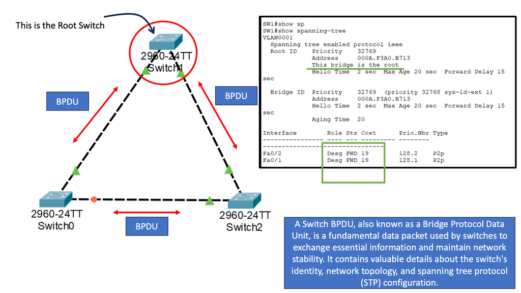
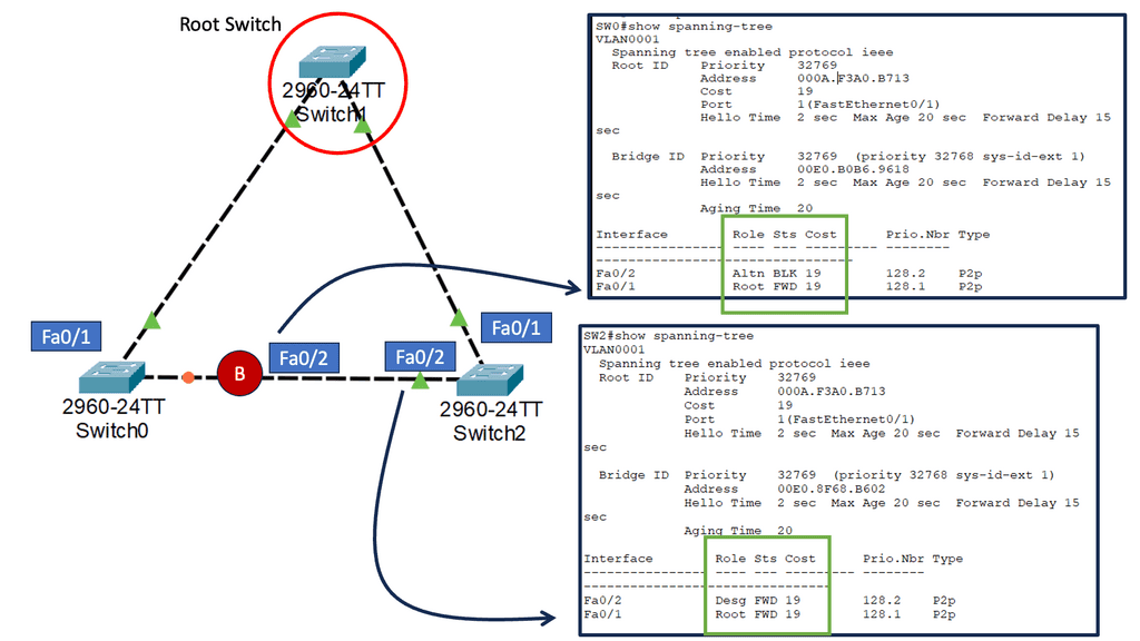
**Designing around STP**
Before we delve into the Cisco ACI overview, let us first address some basics around STP design. The traditional Cisco data center design often leads to poor network design and human error. You don’t want a layer 2 segment between the data center unless you have the proper controls.
Although modularization is still desired in networks today, the general trend has been to move away from this design type, which evolves around a spanning tree, to a more flexible and scalable solution with VXLAN and other similar Layer 3 overlay technologies. In addition, the Layer 3 overlay technologies bring a lot of network agility, which is vital to business success.
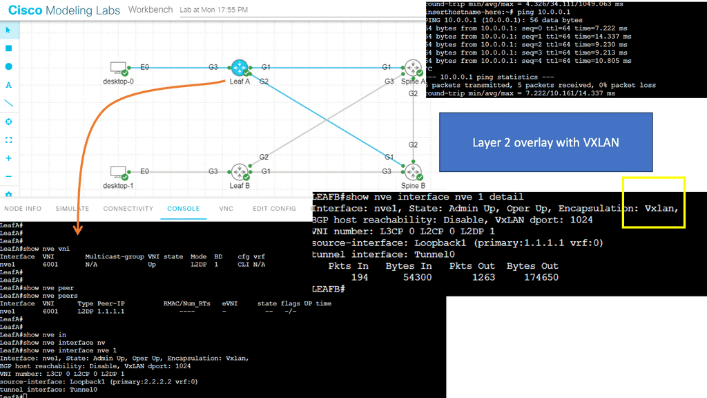
Agility refers to making changes, deploying services, and supporting the business at its desired speed. This means different things to different organizations. For example, a network team can be considered agile if it can deploy network services in a matter of weeks.
In others, it could mean that business units in a company should be able to get applications to production or scale core services on demand through automation with Ansible CLI or Ansible Tower.
Regardless of how you define agility, there is little disagreement with the idea that network agility is vital to business success. The problem is that network agility has traditionally been hard to achieve until now with the ACI data center. Let’s recap some of the leading Cisco data center design transitions to understand fully.
**Challenge: – Layer 2 to the Core**
The traditional SDN data center has gone through several transitions. Firstly, we had Layer 2 to the core. Then, from the access to the core, we had Layer 2 and not Layer 3. A design like this would, for example, trunk all VLANs to the core. For redundancy, you would manually prune VLANs from the different trunk links.
Our challenge with this approach of having Layer 2 to the core relies on the Spanning Tree Protocol. Therefore, redundant links are blocked. As a result, we don’t have the total bandwidth, leading to performance degradation and resource waste. Another challenge is to rely on topology changes to fix the topology.
Data Center Design | Data Center Stability |
Spanning Tree Protocol does have timers to limit the convergence and can be tuned for better performance. Still, we rely on the convergence from the Spanning Tree Protocol to fix the topology, but the Spanning Tree Protocol was never meant to be a routing protocol.
Compared to other protocols operating higher up in the stack, they are designed to be more optimized to react to changes in the topology. However, STP is not an optimized control plane protocol, significantly hindering the traditional data center. You could relate this to how VLANs have transitioned to become a security feature. However, their purpose was originally for performance reasons.
**Required: – Routing to Access Layer**
To overcome these challenges and build stable data center networks, the Layer 3 boundary is pushed further to the network’s edge. Layer 3 networks can use the advances in routing protocols to handle failures and link redundancy much more efficiently.
It is a lot more efficient than Spanning Tree Protocol, which should never have been there in the first place. Then we had routing at the access. With this design, we can eliminate the Spanning Tree Protocol to the core and then run Equal Cost MultiPath (ECMP) from the access to the core.
We can run ECMP as we are now Layer 3 routing from the access to the core layer instead of running STP that blocks redundant links. However, equal-cost multipath (ECMP) routes offer a simple way to share the network load by distributing traffic onto other paths.
ECMP is typically applied only to entire flows or sets of flows. Destination address, source address, transport level ports, and payload protocol may characterize a flow in this respect.
Data Center Design | Data Center Stability |
**Key Point: – Equal Cost MultiPath (ECMP)**
Equal-cost Multipath (ECMP) has many advantages. First, ECMP gives us total bandwidth with equal-cost links. As we are routing, we no longer have to block redundant links to prevent loops at Layer 2. However, we still have Layer 2 in the network design and Layer 2 on the access layer; therefore, parts of the network will still rely on the Spanning Tree Protocol, which converges when there is a change in the topology.
So we may have Layer 3 from the access to the core, but we still have Layer 2 connections at the edge and rely on STP to block redundant links to prevent loops. Another potential drawback is that having smaller Layer 2 domains can limit where the application can reside in the data center network, which drives more of a need to transition from the traditional data center design.
The Layer 2 domain that the applications may use could be limited to a single server rack connected to one ToR or two ToR for redundancy with a Layer 2 interlink between the two ToR switches to pass the Layer 2 traffic.
These designs are not optimal, as you must specify where your applications are set, which limits agility. As a result, another critical Cisco data center design transition was the introduction of overlay data center designs.
**The Cisco ACI version**
Before Cisco ACI 4.1, the Cisco ACI fabric allowed only a two-tier (spine-and-leaf switch) topology. Each leaf switch is connected to every spine switch in the network, and there is no interconnection between leaf switches or spine switches.
Starting from Cisco ACI 4.1, the Cisco ACI fabric allows a multitier (three-tier) fabric and two tiers of leaf switches, which provides the capability for vertical expansion of the Cisco ACI fabric. This is useful for migrating a traditional three-tier architecture of core aggregation access that has been a standard design model for many enterprise networks and is still required today.
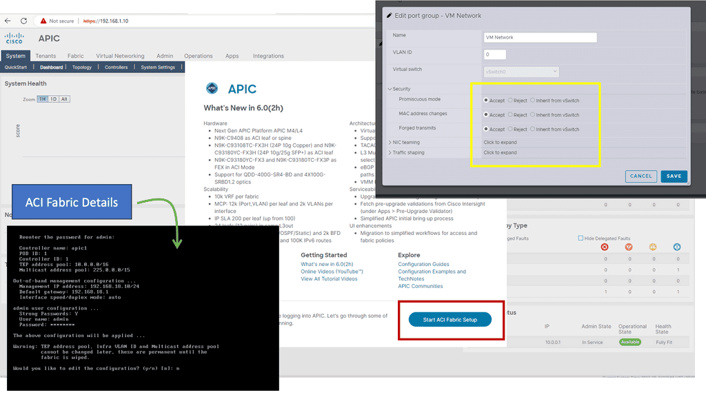
The APIC Controller:
The ACI networks are driven by the Cisco Application Policy Infrastructure Controller ( APIC) database, which works in a cluster from the management perspective. The APIC is the centralized control point; you can configure everything in the APIC.
Consider the APIC to be the brains of the ACI fabric and server as the single source of truth for configuration within the fabric. The APIC controller is a policy engine and holds the defined policy, which tells the other elements in the ACI fabric what to do. This database allows you to manage the network as a single entity.
In summary, the APIC is the infrastructure controller and is the main architectural component of the Cisco ACI solution. It is the unified point of automation and management for the Cisco ACI fabric, policy enforcement, and health monitoring. The APIC is not involved in data plane forwarding.
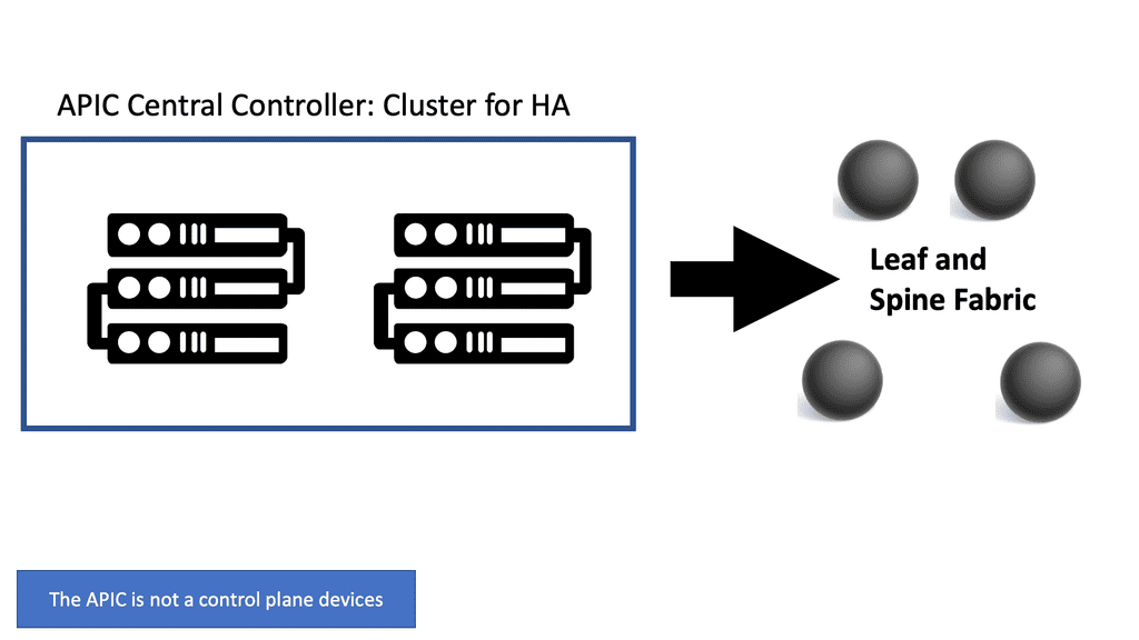
The APIC represents the management plane, allowing the system to maintain the control and data plane in the network. The APIC is not the control plane device, nor does it sit in the data traffic path. Remember that the APIC controller can crash, and you still have forwarded in the fabric. The ACI solution is not an SDN centralized control plane approach. The ACI is a distributed fabric with independent control planes on all fabric switches.
The Leaf and Spine
Leaf-spine is a two-layer data center network topology for data centers that experience more east-west network traffic than north-south traffic. The topology comprises leaf switches (to which servers and storage connect) and spine switches (to which leaf switches connect).
In this two-tier Clos architecture, every lower-tier switch (leaf layer) is connected to each top-tier switch (Spine layer) in a full-mesh topology. The leaf layer consists of access switches connecting to devices like servers.
The Spine layer is the network’s backbone and interconnects all Leaf switches. Every Leaf switch connects to every spine switch in the fabric. The path is randomly chosen, so the traffic load is evenly distributed among the top-tier switches. Therefore, if one of the top-tier switches fails, it would only slightly degrade performance throughout the data center.
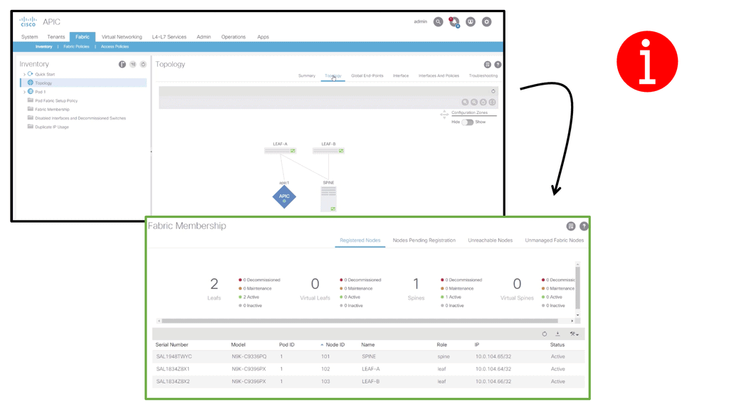
Unlike the traditional Cisco data center design, the ACI data center operates with a Leaf and Spine architecture. Traffic now comes in through a device sent from an end host, known as a Leaf device.
We also have the Spine devices, which are Layer 3 routers with no unique hardware dependencies. In a primary Leaf and Spine fabric, every Leaf is connected to every Spine. Any endpoint in the fabric always has the same distance regarding hops and latency as every other internal endpoint.
The ACI Spine switches are Clos intermediary switches with many vital functions. Firstly, they exchange routing updates with leaf switches via Intermediate System-to-Intermediate System (IS-IS) and rapidly forward packets between them. They also provide endpoint lookup services to leaf switches through the Council of Oracle Protocol (COOP) and handle route reflection to the leaf switches using Multiprotocol BGP (MP-BGP).
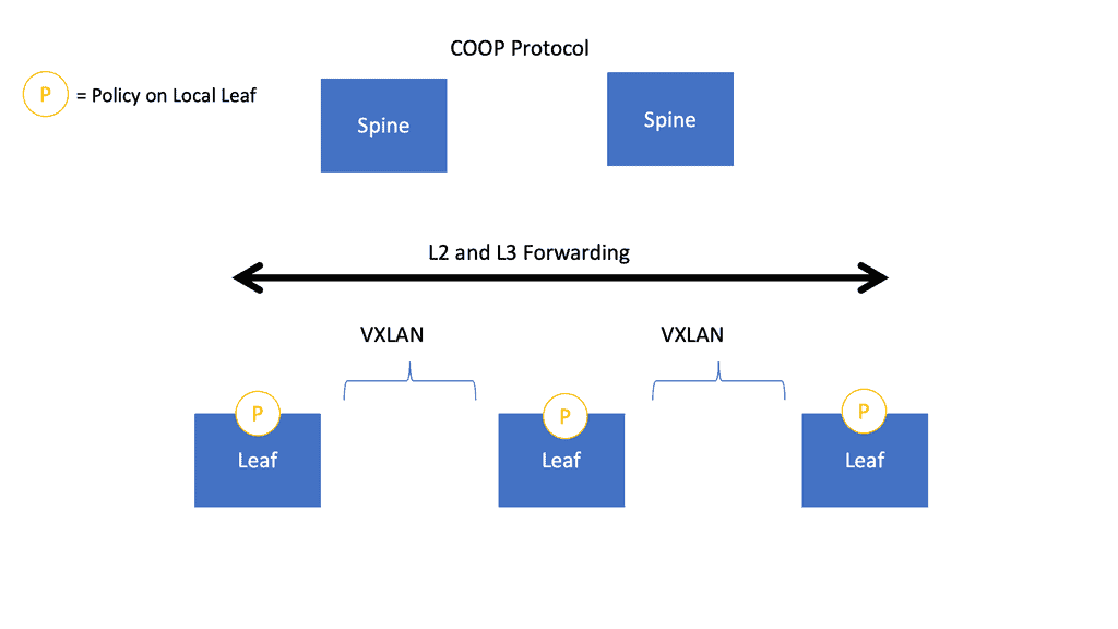
The Leaf switches are the ingress/egress points for traffic into and out of the ACI fabric. They also provide end-host connectivity and are the connectivity points for the various endpoints that the Cisco ACI supports.
The spines act as a fast, non-blocking Layer 3 forwarding plane that supports Equal Cost Multipathing (ECMP) between any two endpoints in the fabric and uses overlay protocols such as VXLAN under the hood. VXLAN enables any workload to exist anywhere in the fabric, so we can now have workloads anywhere in the fabric without introducing too much complexity.
Required: ACI data center and ACI networks
This is a significant improvement to data center networking. We can now have physical or virtual workloads in the same logical Layer 2 domain, even running Layer 3 down to each ToR switch. The ACI data center is a scalable solution as the underlay is specifically built to be scalable as more links are added to the topology and resilient when links in the fabric are brought down due to, for example, maintenance or failure.
ACI Networks: The Normalization event
VXLAN is an industry-standard protocol that extends Layer 2 segments over Layer 3 infrastructure to build Layer 2 overlay logical networks. The ACI infrastructure Layer 2 domains reside in the overlay, with isolated broadcast and failure bridge domains. This approach allows the data center network to grow without risking creating too large a failure domain. All traffic in the ACI fabric is normalized as VXLAN packets.
**Encapsulation Process**
ACI encapsulates external VLAN, VXLAN, and NVGRE packets in a VXLAN packet at the ingress. This is known as ACI encapsulation normalization. As a result, the forwarding in the ACI data center fabric is not limited to or constrained by the encapsulation type or overlay network. If necessary, the ACI bridge domain forwarding policy can be defined to provide standard VLAN behavior where required.
**Making traffic ACI-compatible**
As a final note in this Cisco ACI overview, let us address the normalization process. When traffic hits the Leaf, there is a normalization event. The normalization takes traffic from the servers to the ACI, making it ACI-compatible. Essentially, we are giving traffic sent from the servers a VXLAN ID to be sent across the ACI fabric.
Traffic is normalized, encapsulated with a VXLAN header, and routed across the ACI fabric to the destination Leaf, where the destination endpoint is. This is, in a nutshell, how the ACI Leaf and Spine work. We have a set of leaf switches that connect to the workloads and the spines that connect to the Leaf.
**VXLAN: Overlay Protocol**
VXLAN is the overlay protocol that carries data traffic across the ACI data center fabric. A key point to this type of architecture is that the Layer 3 boundary is moved to the Leaf. This brings a lot of value and benefits to data center design. This boundary makes more sense as we must route and encapsulate this layer without going to the core layer.
ACI networks are revolutionizing how businesses connect and operate in the digital age. Focusing on application-centric infrastructure, they offer enhanced scalability, simplified network operations, and top-notch security. By leveraging ACI networks, businesses can unleash the full potential of their network infrastructure, ensuring seamless connectivity and staying ahead in today’s competitive landscape.

- Fortinet’s new FortiOS 7.4 enhances SASE - April 5, 2023
- Comcast SD-WAN Expansion to SMBs - April 4, 2023
- Cisco CloudLock - April 4, 2023