ACI Security: L4-L7 Services
Data centers are crucial in storing and managing vast information in today's digital age. However, with increasing cyber threats, ensuring robust security measures within data centers has become more critical. This blog post will explore how Cisco Application Centric Infrastructure (ACI) can enhance data center security, providing a reliable and comprehensive solution for safeguarding valuable data.
Cisco ACI segmentation is a cutting-edge approach that divides a network into distinct segments, enabling granular control and segmentation of network traffic. Unlike traditional network architectures, which rely on VLANs (Virtual Local Area Networks), ACI segmentation leverages the power of software-defined networking (SDN) to provide a more flexible and efficient solution. By utilizing the Application Policy Infrastructure Controller (APIC), administrators can define and enforce policies to govern communication between different segments.
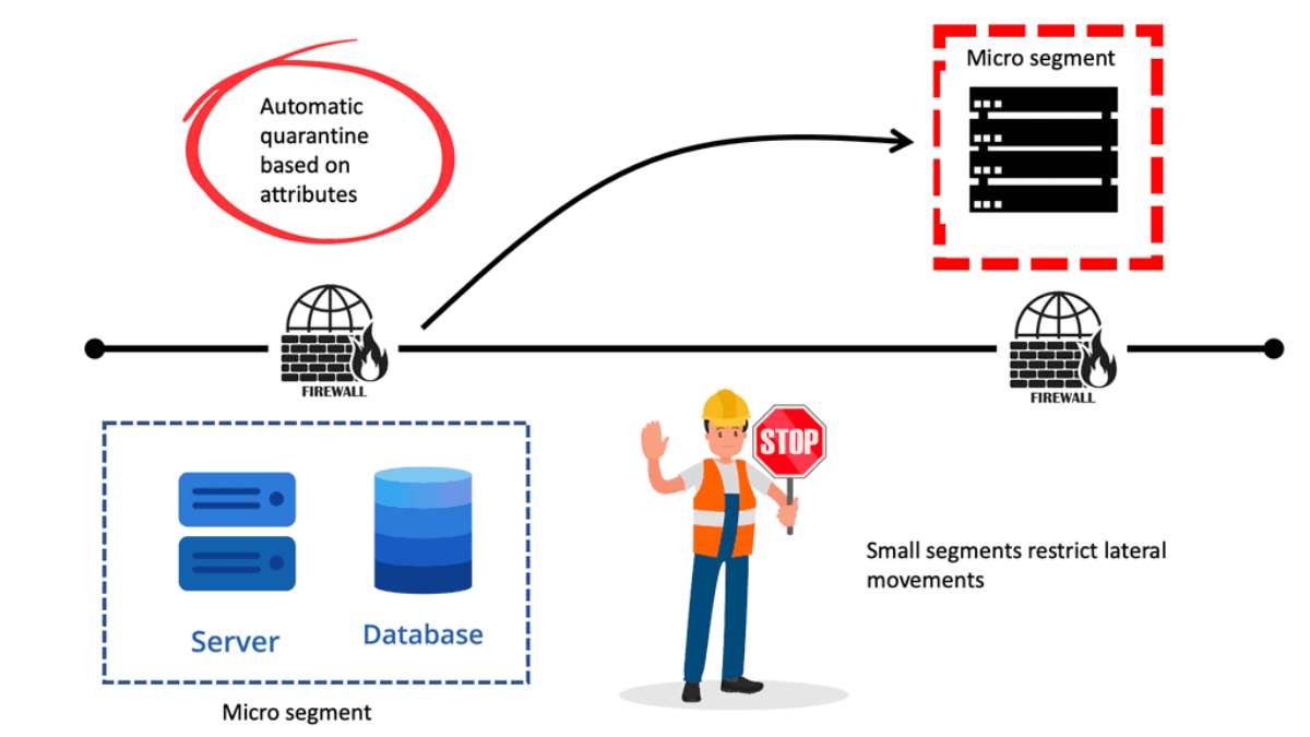
Micro-segmentation has become a buzzword in the networking industry. Leaving the term and marketing aside, it is easy to understand why customers want its benefits.Micro-segmentation's primary advantage is reducing the attack surface by minimizing lateral movement in the event of a security breach.
With traditional networking technologies, this is very difficult to accomplish. However, SDN technologies enable an innovative approach by allowing degrees of flexibility and automation impossible with traditional network management and operations. This makes micro-segmentation possible.Matt Conran
Highlights: Data Center Security
Understanding Network Segmentation
Network segmentation involves dividing a network into multiple smaller segments or subnetworks, isolating different types of traffic, and enhancing security. Cisco ACI offers an advanced network segmentation framework beyond traditional VLAN-based segmentation. It enables the creation of logical network segments based on business policies, applications, and user requirements.
Benefits of Cisco ACI Network Segmentation
– Enhanced Security: With Cisco ACI, network segments are isolated, preventing lateral movement of threats. Segmentation also enables micro-segmentation, allowing fine-grained control over traffic flow and access policies.
– Improved Performance: By segmenting the network, organizations can prioritize critical applications, allocate resources efficiently, and optimize network performance.
– Simplified Management: Cisco ACI’s centralized management allows administrators to define policies for network segments, making it easier to enforce consistent security policies and streamline network operations.
Endpoint Groups
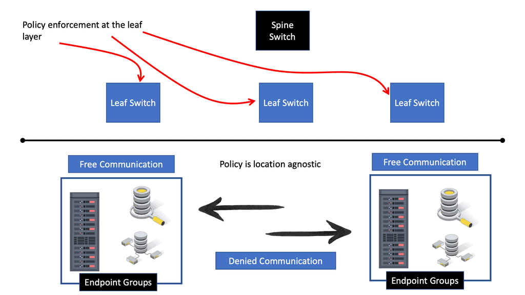
Cisco ACI is one of many data center topologies that need to be secured. It does not consist of a data center firewall and has a zero-trust model. However, more is required; the policy must say what can happen. Firstly, we must create a policy. You have Endpoint groups (EPG) and a contract. These would be the initial security measures. Think of a contract as the policy statement and an Endpoint group as a container or holder for applications of the same security level.
Micro-segmentation
Micro-segmentation has become a buzzword in the networking industry. Leaving the term and marketing aside, it is easy to understand why customers want its benefits.
Micro-segmentation’s primary advantage is reducing the attack surface by minimizing lateral movement in the event of a security breach. With traditional networking technologies, this isn’t easy to accomplish. However, SDN technologies enable an innovative approach by allowing degrees of flexibility and automation that are impossible with traditional network management and operations. This makes micro-segmentation possible.
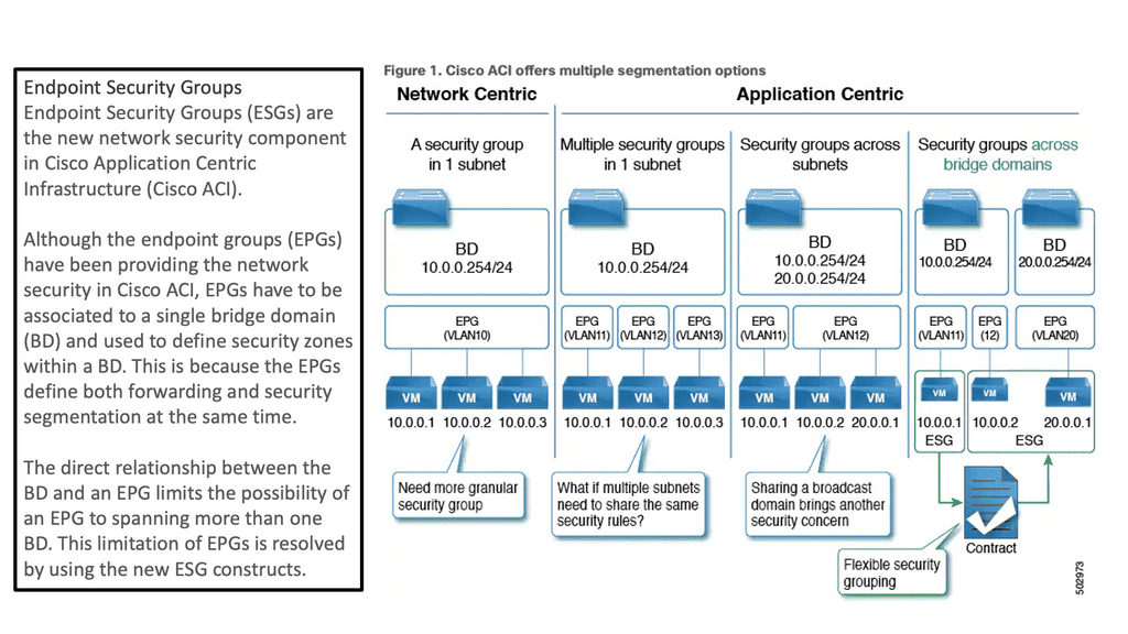
For those who haven’t explored this topic yet, Cisco ACI has ESG. ESGs are an alternative approach to segmentation that decouples it from the early concepts of forwarding and security associated with Endpoint Groups. Thus, segmentation and forwarding are handled separately by ESGs, allowing for greater flexibility and possibilities.
Cisco ACI and ACI Service Graph
The ACI service graph is how Layer 4 to Layer 7 functions or devices can be integrated into ACI. This helps ACI redirect traffic between different security zones of FW or load balancer. The ACI L4-L7 services can be anything from load balancing and firewalling to advanced security services. Then, we have ACI segments that reduce the attack surface to an absolute minimum.
ACI Service Graph
Then, you can add an ACI service graph to insert your security function that consists of ACI L4-L7 services. Now, we are heading into the second stage of security. What we like about this is the ease of use. If your application is removed, all the dots, such as the contract, EPG, ACI service graph, and firewall rules, get released. Cisco calls this security embedded in the application and allows automatic remediation, a tremendous advantage for security functionality insertion.
Related: For pre-information, you may find the following posts helpful:
Back to basic: Cisco ACI Foundations
The ACI, an application-centric infrastructure SDN solution, consists of a spine-leaf fabric with a spine that connects the leaf, and the leaf switches combine the workloads and the security services. The controller manages all of this. So, to create policy, we need groups, and here we have EPG. In an EPG, all applications can talk by default.
Cisco ACI is a software-defined networking (SDN) solution offering a holistic data center security approach. With its policy-driven framework, ACI provides centralized control over security policies, making it easier to manage and enforce consistent security measures across the entire data center infrastructure. By automating security policies, ACI minimizes human error and ensures a robust security posture.
Data Center Security | Data Center Security Cisco ACI Main Security Components
|
Key Features and Benefits of Cisco ACI
Application Visibility and Control
Cisco ACI provides granular visibility into application traffic flows, allowing administrators to identify potential security vulnerabilities and take necessary actions promptly. This visibility enables better control and enforcement of security policies, effectively reducing the attack surface and mitigating threats.
Micro-Segmentation
With ACI’s micro-segmentation capabilities, data centers can be divided into smaller, isolated segments, ensuring the rest remain secure even if one segment is compromised. This approach limits lateral movement within the network, preventing the spread of threats and reducing the overall impact of potential security breaches.
Threat Intelligence and Automation
Cisco ACI integrates with sophisticated threat intelligence systems, leveraging real-time threat feeds and anomaly detection mechanisms. By automating threat response and mitigation, ACI enhances the data center’s ability to detect and neutralize threats promptly, providing a proactive security approach.
Seamless Integration and Scalability
One of Cisco ACI’s critical advantages is its seamless integration with existing data center infrastructure, including virtualized environments and third-party security tools. This flexibility allows organizations to leverage their existing investments while enhancing security measures. Additionally, ACI’s scalability ensures that data center security can evolve alongside business growth and changing threat landscapes.
EPG communication with ACI segments
To control endpoints, we have ACI segments based on Endpoint Groups. Devices within an Endpoint group can communicate, provided they have IP reachability, which the Bridge Domain or VRF construct can supply. Communication between Endpoint groups is not permitted by default. The defaults can be changed, for example, with intra-EPG isolation.
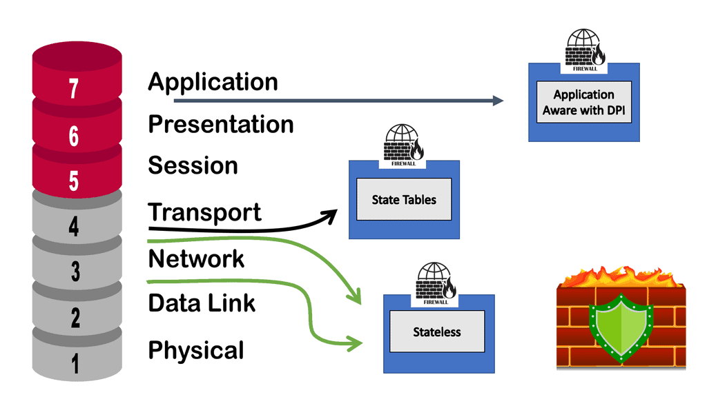
Now, we have a more fine-grained ACI segment, and the endpoint in a single Endpoint group cannot communicate. They need a contract like a stateless reflective access list for external communication. There is no full handshake inspection. So, the ACI contract construct is not a complete data center firewall and needs to provide stateful inspection firewall features.
ACI and applicaton-centric infrastrucure
ACI security addresses security concerns with several application-centric infrastructure security options. You may have heard of the allowlist policy model. This is the ACI security starting point, meaning only something can be communicated if policy allows it. This might prompt you to think that a data center firewall is involved. Still, although the ACI allowlist model does change the paradigm and improves how you apply security, it is only analogous to access control lists within a switch or router.
We need additional protection. So, there is still a need for further protocol inspection and monitoring, which data center firewalls and intrusion prevention systems (IPSs) do very well and can be easily integrated into your ACI network. Here, we can introduce Cisco Firepower Threat Defence (FTD) to improve security with Cisco ACI.
ACI L4-L7 Services
ACI and Policy-based redirect: ACI L4-L7 Services
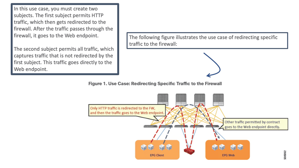
The ACI L4–L7 policy-based redirect (PBR) concept is similar to policy-based routing in traditional networking. In conventional networking, policy-based routing classifies traffic and steers desired traffic from its actual path to a network device as the next-hop route (NHR). For decades, this feature was used in networking to redirect traffic to service devices such as firewalls, load balancers, IPSs/IDSs, and Wide-Area Application Services (WAAS).
In ACI, the PBR concept is similar: You classify specific traffic to steer to a service node by using a subject in a contract. Then, other traffic follows the regular forwarding path, using another subject in the same contract without the PBR policy applied.
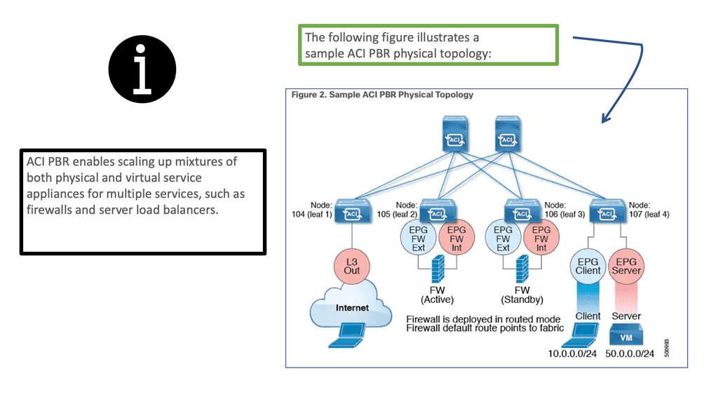
Deploying PBR for ACI L4-L7 services
With ACI policy-based redirect ( ACI L4-L7 services ), firewalls and load balancers can be provisioned as managed or unmanaged nodes without requiring Layer 4 to Layer 7 packages. The typical use cases include providing appliances that can be pooled, tailored to application profiles, scaled quickly, and are less prone to service outages.
In addition, by enabling consumer and provider endpoints to be located in the same virtual routing and forwarding instance (VRF), PBR simplifies the deployment of service appliances. To deploy PBR, you must create an ACI service graph template that uses the route and cluster redirect policies.
After deploying the ACI service graph template, the service appliance enables endpoint groups to consume the service graph endpoint group. Using vzAny can be further simplified and automated. Dedicated service appliances may be required for performance reasons, but PBR can also be used to deploy virtual service appliances quickly.
ACI Segments with Cisco ACI ESG
ACI Segments
We also have an ESG, which is different from an EPG. The EPG is mandatory and is how you attach workloads to the fabric. Then we have the ESG, which is an abstraction layer. Now, we are connected to a VRF, not a bridge domain, so we have more flexibility.
As of ACI 5.0, Endpoint Security Groups (ESGs) are Cisco ACI’s new network security component. Although Endpoint Groups (EPGs) have been providing network security in Cisco ACI, they must be associated with a single bridge domain (BD) and used to define security zones within that BD.
This is because the EPGs define both forwarding and security segmentation simultaneously. The direct relationship between the BD and an EPG limits the possibility of an EPG spanning more than one BD. The new ESG constructs resolve this limitation of EPGs.
Standard Endpoint Groups and Policy Control
As discussed in ACI security, devices are grouped into Endpoint groups, creating ACI segments. This grouping allows the creation of policy enforcement of various types, including access control. Once we have our EPGs defined, we need to create policies to determine how they communicate with each other.
For example, a contract typically refers to one or more ‘filters’ to describe specific protocols & ports allowed between EPGs. We also have ESGs that provide additional security flexibility with more fine-grained ACI segments. Let’s dig a little into the world of contracts in ACI and how these relate to old access control of the past.
Starting ACI Security
ACI Contract
In network terminology, contracts are a mechanism for creating access lists between two groups of devices. This function was initially developed in the network via network devices using access lists and then eventually managed by firewalls of various types, depending on the need for deeper packet inspection. As the data center evolved, access-list complexity increased.
Adding devices to the network that required new access-list modification could become increasingly more complex. While contracts satisfy the security requirements handled by access control lists (ACLs) in conventional network settings, they are a more flexible, manageable, and comprehensive ACI security solution.
Contracts control traffic flow within the ACI fabric between EPGs and are configured between EPGs or between EPGs and L3out. Contracts are assigned a scope of Global, Tenant, VRF, or Application Profile, which limits their accessibility.
Issues with ACL with traditional data center security
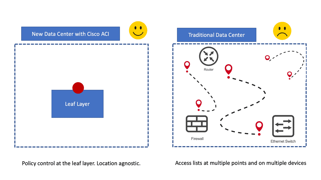
With traditional data center security design, we have standard access control lists (ACLs) with several limitations the ACI fabric security model addresses and overcomes. First, the conventional ACL is very tightly coupled with the network topology. They are typically configured per router or switch ingress and egress interface and are customized to that interface and the expected traffic flow through those interfaces.
Due to this customization, they often cannot be reused across interfaces, much less across routers or switches. In addition, traditional ACLs can be very complicated because they contain lists of specific IP addresses, subnets, and protocols that are allowed and many that are not authorized. This complexity means they are challenging to maintain and often grow as administrators are reluctant to remove any ACL rules for fear of creating a problem.
The ACI fabric security model addresses these ACL issues. Cisco ACI administrators use contract, filter, and label managed objects to specify how groups of endpoints are allowed to communicate.
ACI Security: Topology independence
The critical point is that these managed objects are not tied to the network’s topology because they are not applied to a specific interface. Instead, they are rules that the network must enforce irrespective of where these endpoints are connected.
So, security follows the workloads, allowing topology independence. Furthermore, this topology independence means these managed objects can easily be deployed and reused throughout the data center, not just as specific demarcation points.
The ACI fabric security model uses the endpoint grouping construct directly, so allowing groups of servers to communicate with one another is simple. With a single rule in a contract, we can allow an arbitrary number of sources to communicate with an equally random number of destinations.
ACI Segments with Micro-segmentation in ACI
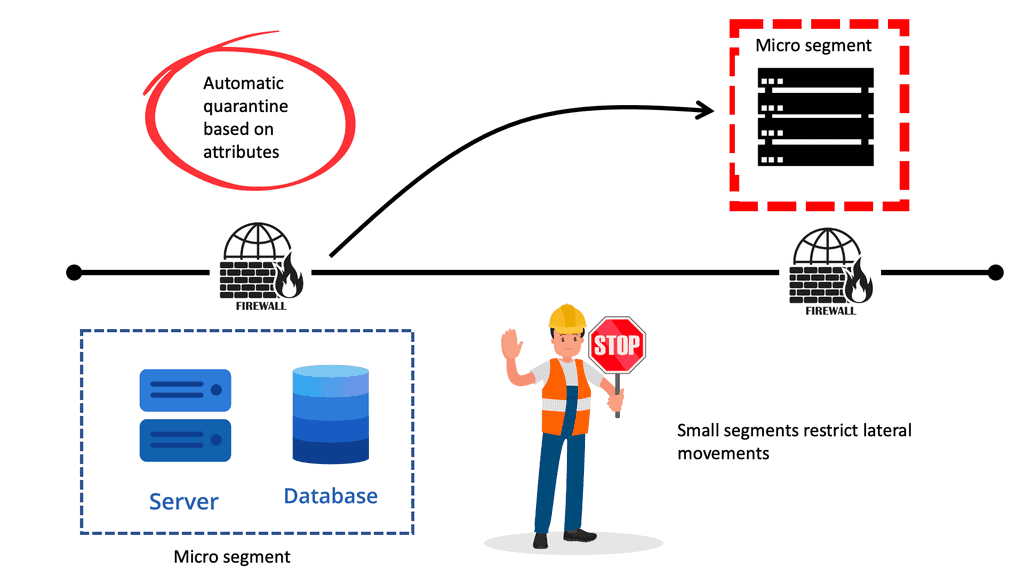
We know that perimeter security is insufficient these days: lateral movement can allow bad actors to move within large segments to compromise more assets once breached. Traditional segmentation based on large zones gives bad actors a large surface to play with. Keep in mind that identity attacks are hard to detect.
How can you tell if a bad actor moves laterally through the network with compromised credentials or if an IT administrator is carrying out day-to-day activities? Micro-segmentation can improve the security posture inside the data center. Now, we can perform segmentation to minimize segment size and provide lesser exposure for lateral movement due to a reduction in the attack surface.
ACI Segments
ACI microsegmentation refers to segmenting an application-centric infrastructure into smaller, more granular units. This segmentation allows for better control and management of network traffic, improved security measures, and better performance. Organizations implementing an ACI microsegmentation solution can isolate different applications and workloads within their network. This allows them to reduce the attack surface of their network, as well as improve the performance of their applications.
Creating ACI segments based on ACI microsegmentation works by segmenting the network infrastructure into multiple subnets. This allows for fine-grained control over network traffic and security policies. Furthermore, it will enable organizations to quickly identify and isolate different applications and workloads within the network.
The benefits of ACI microsegmentation are numerous. By segmenting the network infrastructure into multiple subnets, organizations can create a robust security solution that reduces the attack surface of their network. Additionally, by isolating different applications and workloads, organizations can improve the performance of their applications and reduce the potential for malicious traffic.
Microsegmentation with Cisco ACI
Microsegmentation with Cisco ACI adds the ability to group endpoints in existing application EPGs into new microsegment (uSeg) EPGs and configure the network or VM-based attributes for those uSeg EPGs. This enables you to filter with those attributes and apply more dynamic policies.
We can use various attributes to classify endpoints in an EPG called µEPG. Network-based attributes: IP/MAC VM-based attributes: Guest OS, VM name, ID, vnic, DVS, Datacenter.
Example: Microsegmentation for Endpoint Quarantine
Let us look at a use case. You might have separate EPGs for web and database servers, each containing both Windows and Linux VMs. Suppose a virus affecting only Windows threatens your network, not the Linux environment.
In that case, you can isolate Windows VMs across all EPGs by creating a new EPG called, for example, “Windows-Quarantine” and applying the VM-based operating systems attribute to filter out all Windows-based endpoints.
This quarantined EPG could have more restrictive communication policies, such as limiting allowed protocols or preventing communication with other EPGs by not having any contract. A microsegment EPG can have a contract or not have a contract.
Improving ACI Security
Cisco ACI includes many tools to implement and enhance security and segmentation from day 0. We already mentioned tenant objects like EPGs, and then for policy, we have contracts permitting traffic between them. We also have micro-segmentation with Cisco ACI.
Even though the ACI fabric can deploy zoning rules with filters and act as a distributed data center firewall, the result is comparable to a stateless set of access lists ACLs. As a result, they can provide coarse security for traffic flowing through the fabric.
However, for better security, we can introduce deep traffic inspection capabilities like application firewalls, intrusion detection (prevention) systems (IDS/IPS), or load balancers, which often secure application workloads.
ACI service graph
ACI’s service graph and policy-based redirect (PBR) objects bring advanced traffic steering capabilities to universally utilize any Layer 4 – Layer 7 security device connected in the fabric, even without needing it to be a default gateway for endpoints or part of a complicated VRF sandwich design and VLAN network stitching. So now it has become much easier to implement a Layer 4 – Layer 7 inspection.
You won’t be limited to a single L4-L7 appliance; ACI can chain many of them together or even load balance between multiple active nodes according to your needs. The critical point here is to utilize it universally. The security functions can be in their POD connected to a leaf switch or a pair of leaf switches dedicated to security appliances not located at strategic network points.
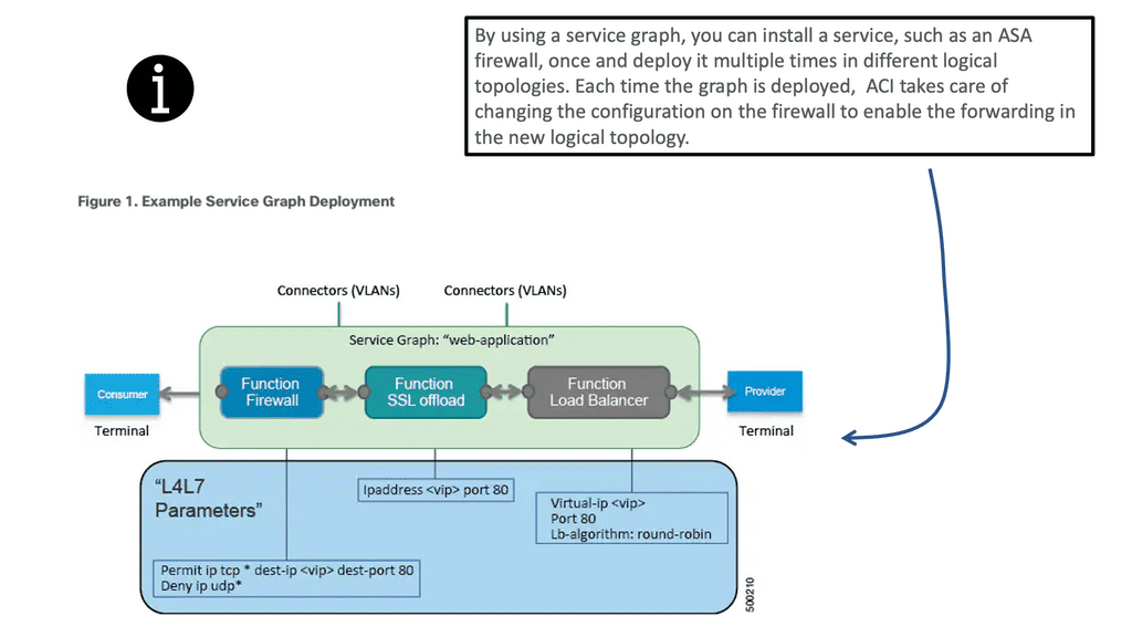
An ACI service graph represents the network using the following elements:
- Function node—A function node represents a function that is applied to the traffic, such as a transform (SSL termination, VPN gateway), filter (firewalls), or terminal (intrusion detection systems). A function within the ACI service graph might require one or more parameters and have one or more connectors.
- Terminal node—A terminal node enables input and output from the service graph.
- Connector—A connector enables input and output from a node.
- Connection—A connection determines how traffic is forwarded through the network.
ACI Service graph: Cisco FTD
With these features, we can now have additional security from Cisco FTD. FTD is a hardware form. If you don’t want physical, it can be virtual on public and private cloud platforms. As you know, ACI can be extended to AWS, and you can use the same data center firewall.
FTD, which stands for Firepower threat defense, comes from a converged solution. We have a converged NGFW/NGIPS on the new Firepower and ASA5500-x platforms. But now we have a single management point with the Firewall Management Center (FMC). So, we take two images and combine them.
Data Center Firewall: Cisco Security Firewall
We can use the Cisco secure firewall for a data center firewall. The architecture of the Cisco secure firewall is modular. A high-end single chassis comprises multiple blade servers, also known as security modules. In addition, the threat defense software runs on a supervisor.
The data center firewall is a highly flexible security solution. Multiple ways exist to enable scalability and ensure resiliency in a Secure Firewall deployment, such as clustering, multi-instance, high availability, and more.
Datacenter firewall: Routed mode
The Cisco secure firewall has different modes of operation. First, it can be deployed in routed mode, in which every interface has an IP address. This design enables you to deploy a Secure Firewall threat defense as a default gateway for your network so that the end users can use the threat defense to communicate with a different subnet or connect to the Internet.
In routed mode, a threat defense acts like a Layer 3 hop. Each interface on a threat defense can be connected to a different subnet, and the threat defense can serve as the default gateway. In addition, the threat defense can route traffic between subnets, like a Layer 3 router.
Data center firewall: Transparent Mode
You can also deploy a threat defense transparently to remain invisible to your network hosts. In transparent mode, a threat defense bridges the inside and outside interfaces into a single Layer 2 network and remains transparent to the hosts. We have no IP addresses on the interfaces and need to change the VLAN between interfaces.
When a threat defense is transparent, the management center does not allow you to assign an IPv4 address to a directly connected interface. As a result, the hosts cannot communicate with any connected interfaces on the threat defense. Unlike with routed mode, you cannot configure the connected interfaces as the default gateway for the hosts.
Data center firewall: FDT Multi-instance DC use case
The higher Cisco secure firewall models also offer multi-instance capability powered by the Docker container technology. It enables you to create and run multiple application instances using a small subset of the total hardware resources of a chassis.
In addition, you can independently manage the threat defense application instances as separate threat defense devices. We are slicing the physical into multiple physicals to allocate each instance to CPU, memory, and disk. We physically cut the hardware in multi or FTD. This use case helps have a separate firewall for different traffic flows in the data center.
Let’s say for compliance, it would help to have a separate firewall for north-to-south traffic and another for east-west traffic. You can also use VRF light instead of multi-instance, giving you more scalability, as you can only have a certain number of multi-instance FTD. So we can use these two features together. If you have a physical device, you can slide it, and in the management domain, we can have different management domains.
Data center security with Service Insertion
In ACI, service devices can also be connected in traditional Layer 2 Transparent/Bridge mode or Layer 3 Routed mode by a front-end and back-end endpoint group (EPG), commonly known as a sandwich design. This type of service integration is called service insertion or service chaining.
Data center security with Service Graph
The concept of a service graph differs from the concept of service insertion. Instead, the service graph specifies that the path from one EPG (the source) to another EPG (the destination) must pass through certain functions by using a contract and internal and external EPGs, also known as “shadow EPGs,” to communicate to service nodes.
Cisco designed the service graph technology to automate the deployment of L4–L7 services in the network. Cisco ACI does not provide the service device separately from a physical device. Still, it can be configured as part of the same logical construct that creates tenants, bridge domains, EPGs, etc. When deploying an L4–L7 ACI service graph, you can choose the following deployment methods:
- Transparent mode: Deploy the L4–L7 device in transparent mode when it bridges the two bridge domains. In Cisco ACI, this mode is called Go-Through mode.
- Routed mode: Deploy the L4–L7 device in Routed mode when the L4–L7 device is routing between the two bridge domains. In Cisco ACI, this mode is called the Go-To mode.
- One-Arm mode: Deploy the L4–L7 device when a load balancer is on a dedicated bridge domain with a single interface.
- Two-Arm mode: Deploy the L4–L7 device in Two-Arm mode when a load balancer is located on a dedicated bridge domain with two interfaces.
- Policy-based redirect (PBR): Deploy the L4–L7 device on a separate bridge domain from the clients or the servers and redirect traffic to it based on protocol and port number.
With policy-based redirect (PBR), the Cisco ACI fabric can redirect traffic between security zones to ACI L4-L7 services, such as a firewall, intrusion-prevention system (IPS), or load balancer, without the need for the L4-L7 device to be the default gateway for the servers or the need to perform traditional networking configuration such as virtual routing and forwarding (VRF) sandwiching or VLAN stitching.
PBR simplifies design because the VRF sandwich configuration is not required to insert a Layer 3 firewall between security zones. The traffic is instead redirected to the node based on the PBR policy.
Data Center Firewall: Secure Firewall Insertion and PBR
Let’s say you have a single application design. We have an EPG that groups applications. These EPGs are tied to the bridge domain, and each bridge domain has a different subnet. This could be a simple 3-tier application with each tier in its own EPG. The fabric performs the routing. Now, we need to introduce additional security and insert a firewall. So, we must have FTD between each EPG, representing the application tiers.
So, what happens is that you create an ACI service graph on top of the contract that will influence the routing decisions. In this case, the ACI relies on PBR to redirect traffic defined in the contract to the security service. So when traffic hits the leaf switch, the firewall will be waiting in a different bridge domain and subnet.
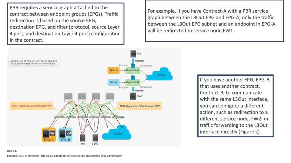
The fabric will create whatever is needed to forward the traffic to the firewall, get inspected, and return to the destination you remove. The firewall and the ACI will return to regular ACI routing. More and less instantaneously. So, PBR is not routing; it is switching. Here, we can pre-empt the switching decisions and forward traffic to the firewall. Because traffic goes to the leaf switch where the PBR rules are enforced, traffic will be sent to the security service defined in the service graph.
We can also use this for microsegment, even if you have all workloads in the same EPG. So, we can leverage PBR to redirect traffic within an EPG/ESG. For example, attaching a service graph to redirect traffic to the FTD for traffic inside an EPG is possible.
Closing Highlights of ACI Security
Application-centric policy model: ACI security provides an abstraction using endpoint groups (EPGs) and contracts to define policies more easily using the language of applications rather than network topology. This overcomes many of the problems we have with standard access lists.
The ACI security allowlist policy approach supports a zero-trust model by denying traffic between EPGs unless a policy explicitly allows it. Make sure you have applications of the same security level in each EPG.
Unified Layer 4 through 7 security policy management with ACI L4-L7 services and ACI service graph: Cisco ACI automates and centrally manages Layer 4 through 7 security policies in the context of an application using a unified application-centric policy model that works across physical and virtual boundaries and third-party devices.
Policy-based segmentation with ACI segments: Cisco ACI enables detailed and flexible segmentation of physical and virtual endpoints based on group policies, thereby reducing the scope of compliance and mitigating security risks.
Integrated Layer 4 security for east-west traffic: The Cisco ACI fabric includes a built-in distributed Layer 4 stateless firewall to secure east-west traffic between application components and across tenants in the data center.
Summary: Data Center Security
In today’s digital landscape, network security is of utmost importance. Organizations constantly seek ways to protect their data and infrastructure from cyber threats. One solution that has gained significant attention is Cisco Application Centric Infrastructure (ACI). In this blog post, we explored the various aspects of Cisco ACI Security and how it can enhance network security.
Section 1: Understanding Cisco ACI
Cisco ACI is a policy-based automation solution providing a centralized network management approach. ACI offers a flexible and scalable network infrastructure combining software-defined networking (SDN) and network virtualization.
Section 2: Key Security Features of Cisco ACI
2.1 Micro-Segmentation:
One of Cisco ACI’s standout features is micro-segmentation. It allows organizations to divide their network into smaller segments, providing granular control over security policies. This helps limit threats’ lateral movement and contain potential breaches.
2.2 Integrated Security Services:
Cisco ACI integrates seamlessly with various security services, such as firewalls, intrusion prevention systems (IPS), and threat intelligence platforms. This integration ensures a holistic security approach and enables real-time threat detection and prevention.
Section 3: Policy-Based Security
3.1 Policy Enforcement:
With Cisco ACI, security policies can be defined and enforced at the application level. This means that security rules can follow applications as they move across the network, providing consistent protection. Policies can be defined based on application requirements, user roles, or other criteria.
3.2 Automation and Orchestration:
Cisco ACI simplifies security management through automation and orchestration. Security policies can be applied dynamically based on predefined rules, reducing the manual effort required to configure and maintain security settings. This agility helps organizations respond quickly to emerging threats.
Section 4: Threat Intelligence and Analytics
4.1 Real-Time Monitoring:
Cisco ACI provides comprehensive monitoring capabilities, allowing organizations to gain real-time visibility into their network traffic. This includes traffic behavior analysis, anomaly detection, and threat intelligence integration. Proactively monitoring the network can identify and mitigate potential security incidents promptly.
4.2 Centralized Security Management:
Cisco ACI offers a centralized management console where security policies and configurations can be easily managed. This streamlines security operations, simplifies troubleshooting, and ensures consistent policy enforcement across the network.
Conclusion:
Cisco ACI is a powerful solution for enhancing network security. Its micro-segmentation capabilities, integration with security services, policy-based security enforcement, and advanced threat intelligence and analytics make it a robust choice for organizations looking to protect their network infrastructure. By adopting Cisco ACI, businesses can strengthen their security posture and mitigate the ever-evolving cyber threats.
- Fortinet’s new FortiOS 7.4 enhances SASE - April 5, 2023
- Comcast SD-WAN Expansion to SMBs - April 4, 2023
- Cisco CloudLock - April 4, 2023

