
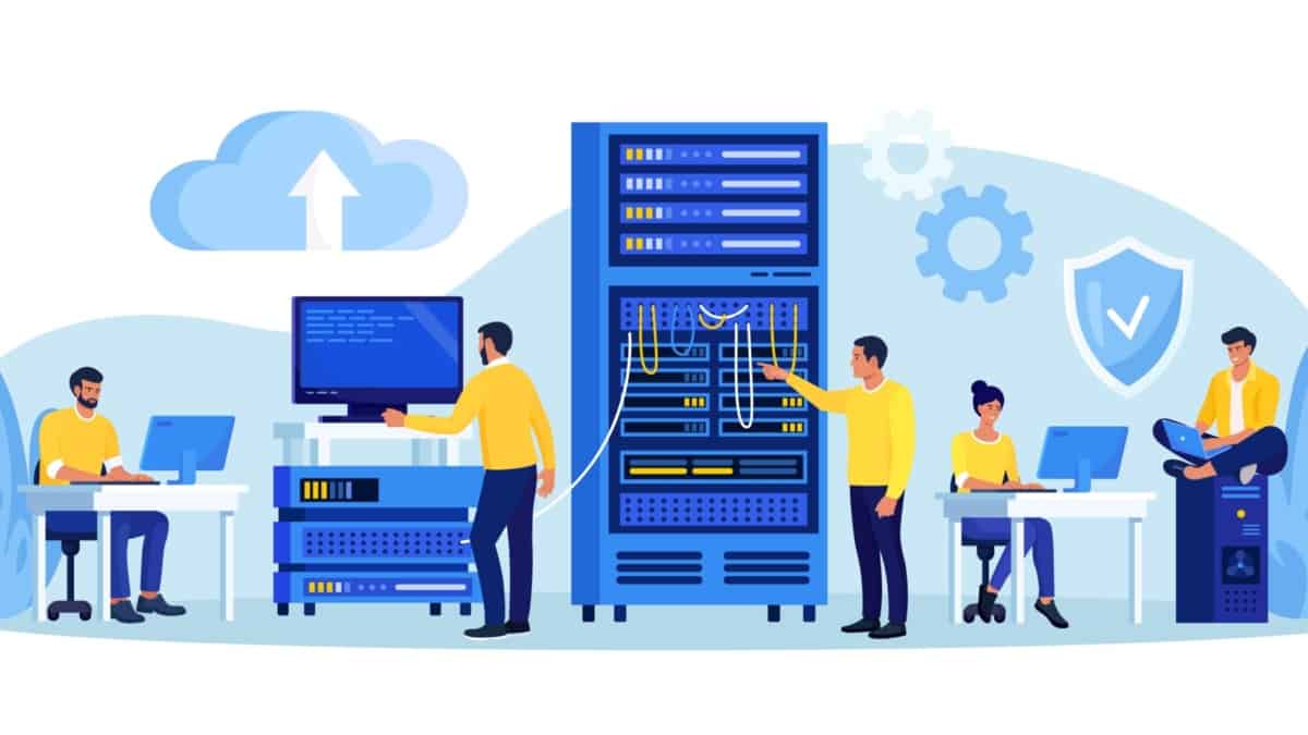
SDN Data Center: Architecture, Fabrics and Programmable Networks
Modern data centers must connect increasingly distributed applications, virtual machines, containers and services while maintaining predictable performance, security and availability. Software-Defined Networking (SDN) introduces a programmable approach to network control, enabling operators to express policies, automate configuration and coordinate network behaviour across a shared infrastructure.
The shift is not simply about replacing the command-line interface with software. It is about changing how network intent is translated into forwarding behaviour, how infrastructure responds to workload changes, and how engineers verify that the network is operating as designed. Understanding this distinction is essential when evaluating SDN architectures and deciding where automation and centralised control provide real operational value.
Traditional data center designs often relied on hierarchical switching, Layer 2 extension and Spanning Tree Protocol (STP) to manage redundant connectivity. As east-west traffic, virtualisation and workload mobility increased, operators adopted routed leaf-spine fabrics, Equal-Cost Multi-Path (ECMP) forwarding and overlay technologies such as VXLAN. SDN can coordinate these mechanisms through policy and automation, but the exact implementation depends on the platform and architecture.
From network infrastructure to programmable fabric
The SDN control model
SDN separates the definition and coordination of network behaviour from packet forwarding. A controller or control system can translate application requirements and network policies into device configuration, forwarding rules or other platform-specific actions. The forwarding devices continue to process packets using their programmed state.
This is a conceptual model, not a requirement that every SDN deployment use one physical controller or a single centralised control process. Production architectures may distribute controller functions, retain routing protocols on network devices, and combine central policy with local forwarding decisions.
Why data center design matters
A programmable network is only as effective as the fabric underneath it. The physical topology, routing design, link capacity, failure domains and overlay configuration all influence how applications perform. Centralised policy cannot compensate for every physical bottleneck or incorrect forwarding assumption.
For this reason, SDN must be considered alongside data center architecture. A resilient leaf-spine fabric can provide multiple routed paths, while ECMP distributes eligible flows across equal-cost routes. VXLAN can provide virtual Layer 2 segments across a Layer 3 underlay, and policy systems can help coordinate tenant isolation and service connectivity.
Separate desired network intent from actual forwarding state. A controller may report that a policy has been deployed, but operational verification must still establish reachability, path availability, segmentation, resource utilisation and application connectivity.
What this engineering guide covers
This guide develops the subject from the foundations of SDN through the design and operation of a modern data center fabric. It connects the architectural concepts to the protocols, forwarding mechanisms and operational evidence that engineers use to troubleshoot real networks.
From theory to engineering evidence
Throughout the guide, the emphasis is on understanding cause and effect. When a link fails, which paths remain available? When a virtual workload moves, what must change in the network? When a controller applies a new policy, how can an engineer confirm that the intended result has reached the forwarding infrastructure?
These are operational questions, not just architectural definitions. Answering them requires an understanding of topology, routing, encapsulation, policy and telemetry—and the ability to correlate evidence from different parts of the network.
The first section examines what Software-Defined Networking actually changes, how the application, control and infrastructure responsibilities relate to one another, and why SDN should not be treated as synonymous with OpenFlow or a single controller product.
Engineering Guide · Navigation
Explore the SDN Data Center
Follow the engineering path from programmable network architecture through resilient fabrics and overlays to automation, troubleshooting and operational security. Select a topic to jump directly to its introduction.
Understanding SDN Architecture and Programmability
Software-Defined Networking separates network policy and control from packet forwarding through programmable interfaces and coordinated management. Explore the application, control and infrastructure layers, understand how they interact, and examine why SDN is an architectural approach rather than a single protocol or controller product.
SDN Architecture: The Control Plane and Network Programmability
Software-Defined Networking changes how network behaviour is configured, coordinated and managed. Rather than requiring engineers to configure every device independently for each network-wide change, SDN introduces software-based control and policy mechanisms that can coordinate infrastructure through programmable interfaces.
The central architectural idea is the separation of responsibilities between the systems that express network requirements, the control functions that translate those requirements into network behaviour, and the devices that forward packets. This separation can simplify operations and enable automation, but it does not mean that every routing decision moves into one central controller.
To understand an SDN data center, engineers must distinguish the control plane from the data plane, understand how controllers interact with network devices, and establish how a desired policy becomes observable forwarding behaviour.
The three conceptual layers of SDN
These layers provide a useful architectural model rather than a mandatory physical deployment. Some platforms combine functions, distribute controller services across multiple systems, or retain substantial control-plane intelligence on individual switches and routers.
Control plane versus data plane
The control plane determines or coordinates how traffic should be forwarded. Depending on the architecture, it can include routing protocols, topology discovery, path calculation, policy processing and controller logic.
The data plane performs the actual packet-handling work. It examines packet headers, consults forwarding information and applies actions such as forwarding, encapsulation, decapsulation, marking or dropping. High-speed switches commonly execute these operations in specialised hardware.
Consider a workload that needs connectivity to an application in another network segment. The management system may express the required communication policy. A controller or orchestration system translates it into platform-specific configuration. Switches and routers then apply the resulting forwarding and enforcement state to real packets.
Each stage introduces a separate verification requirement. A policy can be accepted by the management system but fail during deployment; configuration can be installed while a route is missing; and a valid route can exist while a security rule prevents the application flow.
A controller's intended network state, a device's installed configuration and the forwarding behaviour observed by a packet capture are three different forms of evidence. Reliable troubleshooting correlates them instead of assuming that success at one layer proves success at every other layer.
What does an SDN controller actually do?
An SDN controller provides software-based mechanisms for coordinating network behaviour. Its responsibilities depend on the product and architecture, but can include maintaining a topology view, translating policy, calculating paths, managing forwarding rules, programming devices and collecting operational information.
Some controllers directly install forwarding entries in compatible switches. Others configure devices through management APIs, coordinate existing routing protocols, or distribute policy through agents and platform-specific components. An SDN controller should therefore be understood by the functions it performs, not simply by its product name.
Controller responsibilities
Northbound and southbound interfaces
SDN architectures commonly describe interfaces according to the direction in which information or control is exchanged. Northbound interfaces allow applications and orchestration systems to interact with controller services. Southbound interfaces connect control functions to network infrastructure.
| Interface | Purpose | Examples |
|---|---|---|
| Northbound | Expose network services, intent or operational information to applications and orchestration systems. | REST APIs, controller SDKs and policy interfaces. |
| Southbound | Exchange configuration, control information or forwarding instructions with infrastructure. | OpenFlow, NETCONF, RESTCONF and platform-specific APIs, depending on the implementation. |
| Telemetry and feedback | Return device state, counters, events and performance information for monitoring and verification. | Streaming telemetry, counters, logs and event notifications. |
These categories describe interface roles, not a requirement that every protocol be used in every SDN design. NETCONF and RESTCONF, for example, are management protocols rather than equivalents of OpenFlow's flow-programming model. The correct interface depends on the device capabilities and the operation being performed.
SDN and OpenFlow are not the same thing
OpenFlow is a protocol historically associated with SDN that allows a controller to communicate with compatible forwarding devices and manage flow-table behaviour. It helped demonstrate how packet forwarding could be programmed through an external control system.
SDN is the broader architectural approach. A network can use SDN principles without using OpenFlow. Modern data center platforms may combine controller-based policy, routing protocols, management APIs, overlays and distributed forwarding intelligence.
Open Networking Foundation initiatives helped advance the development and standardisation of SDN concepts and OpenFlow. In practice, engineers should evaluate the interfaces, supported features and operational model of the specific implementation rather than assume that every SDN product uses the same protocol stack.
Centralised policy does not mean one central forwarding engine
The term centralised control can be misleading if interpreted too literally. A controller may provide a global policy view while switches continue to forward packets locally. Distributed routing protocols can also operate alongside a controller, exchanging reachability information and maintaining forwarding tables.
This combination is particularly important in data centers. A controller might define tenant segmentation and application connectivity, while the underlay uses BGP or an IGP to establish IP reachability between leaf and spine switches. ECMP can then distribute eligible traffic across available equal-cost paths.
Separating these responsibilities allows policy orchestration and packet forwarding to work together without requiring every packet to pass through the controller.
Automation, consistency and failure handling
Programmability enables engineers to express repeatable network changes in software. Rather than manually configuring every device, an automation workflow can generate and deploy configuration, validate prerequisites and check the resulting state.
Automation does not automatically guarantee correctness. Incorrect intent, incomplete device support, stale topology data, failed deployment or partial updates can produce inconsistent outcomes. A robust implementation needs validation, access controls, change tracking, rollback or recovery procedures, and independent operational verification.
What to verify during an SDN change
Applying the architecture to a data center
Imagine a tenant needs a new application segment that can communicate with a database but must remain isolated from another tenant. The application or orchestration layer defines the connectivity intent. The control system translates it into the supported policy and configuration. The data center fabric provides the actual transport, while security enforcement ensures that only permitted communication is allowed.
The engineering task is to trace this chain end to end. Confirm that the policy exists, that the relevant devices received it, that the underlay can reach the required destinations, and that the overlay and security configuration support the intended traffic.
SDN provides programmable coordination of network behaviour. The control plane determines or coordinates how the network should operate, while the data plane performs packet forwarding. Successful operation depends on translating intent into valid device state and verifying the resulting traffic behaviour.
In the interactive lab, inspect a conceptual SDN data center and follow a policy change from application intent through controller processing to infrastructure configuration and packet forwarding. Examine the control and data planes separately, identify the role of northbound and southbound interfaces, and investigate what happens when intended policy and observed network state disagree.
SDN Architecture & Programmability
Maintains network state, applies policy and determines which forwarding behaviour should be installed.
Matches packets against forwarding entries and performs actions such as output, drop or header modification.
| Match | Action | State |
|---|---|---|
| 10.1.0.10 → .20 | Pending | — |
Engineer Challenge
Run the packet trace, inject a link failure, and continue the simulation. Can the network deliver traffic without using the failed primary link?
Leaf–Spine Fabrics, ECMP and Network Resilience
Modern data centers need predictable connectivity, usable redundant paths and reliable recovery from failures. Discover how leaf–spine topologies, routed underlays, BGP and Equal-Cost Multipath work together, and learn why routing convergence, forwarding state and available capacity must all be considered during an incident.
SDN Data Center Fabrics: Leaf–Spine, ECMP and Resilient Forwarding
A programmable network needs a dependable transport foundation. In modern data centers, that foundation is often a routed leaf–spine fabric: a predictable topology designed to provide multiple paths, scalable east–west connectivity and fast recovery when links or devices fail.
Software-defined control and the physical fabric solve different problems. SDN provides mechanisms to coordinate policy and network configuration. The fabric provides the paths over which packets travel. Understanding how these parts work together is essential when designing, automating or troubleshooting a data center.
Why data centers moved beyond large Layer 2 domains
Traditional data center designs often relied on extensive Layer 2 connectivity. Spanning Tree Protocol (STP) prevents Layer 2 loops by blocking selected redundant paths. This protects the network from looping Ethernet frames, but some physical links may not forward traffic while the topology is stable.
As east–west traffic between servers, application tiers and storage increased, engineers looked for designs that could use redundant links more effectively. Routed leaf–spine fabrics provide multiple Layer 3 paths and can use Equal-Cost Multipath (ECMP) forwarding where supported and correctly configured.
This does not make STP obsolete. Layer 2 still exists at access edges and within particular designs. The key architectural choice is to limit where Layer 2 must extend and use routed connectivity for the scalable fabric wherever the design permits.
Understanding the leaf–spine topology
Simplified illustration: production fabrics generally connect each leaf to multiple spines. The actual number of devices, link speeds, redundancy and routing design depend on capacity and availability requirements.
Leaf switches connect directly to servers, hypervisors, storage systems or other network edges. Spine switches provide transit between leaves. In a conventional two-tier design, leaf switches connect to the spine layer rather than to one another.
Leaf layer
Provides workload attachment, Layer 3 gateways where required, access policy and connectivity to the fabric. It is commonly the point where server-facing links enter the network.
Spine layer
Provides high-capacity transit between leaves. Multiple spines create alternate paths and help scale fabric capacity without requiring every leaf to connect directly to every other leaf.
Underlay
The routed IP network connecting the fabric devices. It provides reachability between relevant interfaces and endpoints used by the routing and overlay systems.
Overlay
A logical network built over the underlay, often using VXLAN to carry tenant or segment traffic between tunnel endpoints. The overlay does not remove the need for working underlay reachability.
ECMP: using multiple equal-cost paths
Equal-Cost Multipath routing allows a router to install multiple eligible next hops for a destination when the routing system determines that those paths have the same cost. Instead of selecting only one next hop, the device can distribute eligible flows across the available paths.
In a leaf–spine fabric, a leaf may have a route to a remote subnet through several spine switches. If the routes qualify for ECMP, the leaf can use those next hops to distribute traffic across the fabric.
Leaf 1 has two equal-cost routes to a remote destination: one through Spine 1 and one through Spine 2. If both next hops are installed and usable, eligible flows can be spread across the two paths. If a path becomes unavailable, routing and forwarding mechanisms can remove or stop using that next hop.
How ECMP distributes traffic
Many implementations use a hash calculated from packet or flow fields to select a next hop. This commonly keeps packets belonging to the same flow on the same path, reducing packet reordering. The exact hash inputs and resilience behaviour vary by platform.
ECMP does not necessarily divide every individual flow evenly. A large flow can dominate one path, and uneven flow sizes can create unequal utilisation even when the hashing mechanism is working correctly. Some platforms support additional techniques to improve distribution or reduce disruption when the set of next hops changes.
How BGP and other routing protocols support the fabric
A routed data center fabric needs a way to exchange reachability information. BGP is widely used in data center underlays because it provides policy controls, scalable route exchange and well-defined operational mechanisms. Other routing protocols, such as OSPF or IS-IS, can also be used depending on the design.
With an eBGP underlay, adjacent fabric devices in different autonomous systems exchange routes using external BGP sessions. Some designs use iBGP with a suitable route-reflection or control-plane architecture. The choice depends on the topology, operational model and requirements.
BGP multipath allows multiple paths to be installed when they satisfy the implementation's multipath eligibility rules and relevant configuration. Equal-cost forwarding is not guaranteed simply because BGP has learned more than one route: engineers must verify which paths were selected, which next hops were installed and how the forwarding hardware uses them.
| Component | Primary role | What to verify |
|---|---|---|
| BGP or IGP | Exchanges routes and establishes network reachability. | Neighbour state, learned routes, route selection and next hops. |
| ECMP | Uses multiple eligible equal-cost forwarding paths. | Installed next hops, path eligibility and traffic distribution. |
| Forwarding hardware | Applies the programmed forwarding decision to packets. | Hardware programming, counters, drops and interface state. |
| SDN or automation layer | Coordinates policy, configuration and operational workflows. | Deployment status, device consistency and observed results. |
Link failures and convergence
Redundant physical links do not automatically guarantee uninterrupted service. When a link or spine fails, the network must detect the failure, update relevant state and move traffic onto usable paths. The speed and impact of that process depend on the failure-detection method, routing protocol behaviour, hardware support and topology.
Some platforms support fast reroute or other mechanisms that can reduce interruption before full routing convergence completes. These features have specific design and support requirements. They should be validated under realistic failure conditions instead of assumed to be active by default.
Capacity planning and oversubscription
Fabric resilience is also a capacity question. A design may have multiple paths but still experience congestion if surviving links cannot carry the offered load after a failure.
Oversubscription compares the potential aggregate bandwidth offered by downstream links with the available upstream capacity. The acceptable ratio depends on the workloads. Traffic patterns dominated by short server-to-server exchanges can have different needs from storage traffic, distributed analytics or GPU clusters with heavy all-to-all communication.
Engineers should size the fabric for normal operation and consider what happens when one or more links or devices are unavailable. Monitoring utilisation, queue drops, latency and flow distribution helps establish whether the fabric behaves as designed.
Where SDN fits into fabric operations
SDN does not replace the physical fabric or make routing protocols unnecessary. Instead, programmable systems can standardise device provisioning, apply configuration templates, coordinate policy, collect telemetry and validate expected state.
For example, an automation system may deploy a new leaf switch with consistent interface settings, routing configuration and monitoring. The routing protocol still establishes reachability, while the automation layer checks that the device joins the fabric and receives the intended configuration.
This division of responsibilities supports repeatability while preserving the importance of routing fundamentals. If a workload cannot reach a destination, engineers still need to inspect the route, next hop, interface state, forwarding entry and any relevant policy or overlay dependency.
A routed leaf–spine fabric provides a scalable transport foundation. Routing establishes reachability, ECMP can use multiple eligible paths, and failure handling determines how traffic recovers. SDN and automation help coordinate and verify the design, but correct forwarding, capacity and resilience must still be proven through operational evidence.
In the interactive lab, trace traffic between two leaf switches through multiple spines. Inspect route selection and ECMP next hops, simulate a link failure, and compare the expected path with the surviving forwarding state. The investigation will distinguish routing convergence from application recovery and highlight how to verify whether remaining paths have sufficient capacity.
VXLAN Overlays and Logical Network Segmentation
Virtualised networks allow multiple logical environments to share a physical fabric while maintaining defined connectivity boundaries. Follow the packet through the VXLAN encapsulation process, examine VTEPs and VNIs, and learn how underlay reachability, endpoint discovery, MTU and security policy affect end-to-end communication.
Network Virtualisation: VXLAN, Overlays and Tenant Segmentation
Network virtualisation separates logical network design from the physical links and switches that carry traffic. It allows an infrastructure team to create multiple isolated network segments over a shared IP fabric, supporting multi-tenant environments, flexible workload placement and consistent policy.
Software-defined networking can help automate how these logical networks are created and managed. In many data centers, VXLAN provides the overlay encapsulation, while the routed IP underlay supplies connectivity between the devices that terminate those tunnels.
Underlay and overlay: two different responsibilities
The underlay is the physical or routed transport network. It provides IP reachability between fabric endpoints, including Virtual Tunnel Endpoints (VTEPs) when VXLAN is used.
The overlay is a logical network carried across that transport. VXLAN encapsulates an inner Ethernet frame inside an outer transport packet, allowing Layer 2 segments to extend across an IP network without requiring the underlay to behave as one large Layer 2 domain.
Conceptual packet path. The underlay forwards using the outer IP header; the overlay identifies the logical segment and carries the original Ethernet frame.
What VXLAN contributes
VXLAN is an encapsulation technology, not a complete network automation or policy system by itself. It carries Ethernet frames over an IP network and uses a 24-bit VXLAN Network Identifier (VNI) to identify a logical Layer 2 segment.
VTEP
A VXLAN Tunnel Endpoint performs encapsulation and decapsulation. It maps local traffic to the appropriate VXLAN segment and sends encapsulated traffic toward the remote VTEP.
VNI
The VXLAN Network Identifier distinguishes logical VXLAN segments. A VNI is not the same thing as a VLAN ID, even though implementations can map VLANs to VNIs.
Outer IP header
Identifies the tunnel endpoints and enables the underlay routers to forward the encapsulated packet toward the destination VTEP.
Inner Ethernet frame
Carries the original workload traffic through the overlay. The destination VTEP decapsulates the packet and forwards the inner frame within the correct logical segment.
VXLAN provides encapsulation and segment identification. It does not, by itself, determine every endpoint location, distribute all required forwarding information, enforce a complete security policy or guarantee underlay reachability. Those responsibilities depend on the control-plane design, platform and surrounding network services.
How endpoints and VTEPs discover each other
A VTEP needs sufficient forwarding information to reach the correct remote VTEP and deliver traffic to the intended endpoint. Different VXLAN designs use different control-plane approaches.
Control-plane learning
Some deployments use data-plane learning, where information about remote endpoints is learned from traffic. Other designs use a control plane to distribute endpoint reachability before traffic needs to be forwarded. In BGP EVPN designs, BGP EVPN distributes MAC and IP reachability information and supports additional services according to the configured architecture.
A control plane can reduce dependence on flood-and-learn behaviour and improve how endpoint information is distributed across a fabric. However, correct operation still depends on consistent configuration, route exchange, VNI membership, endpoint learning and the availability of the underlying transport.
Tenant segmentation and policy
Virtual networks allow different applications, customers or organisational units to share physical infrastructure while maintaining logical separation. For example, production services, development workloads and shared infrastructure services can occupy different logical segments.
Segmentation is not automatically equivalent to a complete security boundary. Engineers must determine which communication is allowed between segments and implement the appropriate routing, gateway controls, distributed firewall rules, access policies or other enforcement mechanisms.
| Design element | Question it answers | Typical verification |
|---|---|---|
| VLAN / VNI mapping | Which logical segment does this traffic belong to? | VLAN configuration, VNI mapping and segment membership. |
| VTEP reachability | Can the source tunnel endpoint reach the destination VTEP? | Underlay routes, next hops and IP connectivity. |
| Endpoint information | Where should the destination MAC or IP be forwarded? | MAC tables, ARP/ND state and control-plane advertisements. |
| Inter-segment policy | Is communication between these segments permitted? | Gateway routes, ACLs, firewall rules and policy counters. |
| MTU | Can encapsulated packets traverse the underlay without unwanted fragmentation or drops? | Interface MTU, encapsulation overhead and packet-drop counters. |
Why the underlay MTU matters
VXLAN adds outer headers around the original Ethernet frame. This increases packet size. If the underlay MTU is not designed to accommodate the encapsulated packet, traffic may be fragmented where permitted or dropped, depending on the packet size, configuration and forwarding behaviour.
MTU problems can be deceptive: small packets may work while larger transfers fail or perform poorly. A reliable deployment validates the intended MTU end to end and checks counters and packet behaviour rather than assuming that successful ping tests prove every packet size will work.
How SDN and automation manage virtual networks
An SDN controller or automation platform can provide a consistent workflow for provisioning logical networks, mapping segments, distributing configuration and applying policy. Depending on the implementation, it may also integrate with virtualisation platforms, IP address management, inventory and telemetry systems.
The implementation model varies. Some systems use a central orchestration layer to coordinate configuration across devices; others rely on distributed control-plane protocols, local device decisions or a combination of both. A central management interface does not necessarily mean all packet-forwarding decisions are made by one central process.
Overlay troubleshooting: follow the packet in layers
Network virtualisation creates logical networks over shared transport. VXLAN carries Layer 2 frames across an IP underlay, while VTEPs, VNIs, endpoint reachability and policy determine how traffic is delivered. Troubleshooting should separate underlay reachability, overlay state and security enforcement instead of treating the virtual network as one opaque system.
The planned interactive lab will trace a packet from a source workload through its VTEP and routed underlay to a remote endpoint. Investigate a missing route, incorrect segment mapping or policy restriction, then identify which evidence proves whether the fault belongs to the underlay, overlay or security layer.
Leaf–Spine Fabrics, ECMP & Resilience
Engineer Challenge
Send several packets, fail Spine 1's path, then send more traffic. Check whether the selected path avoids the failed link.
SDN Controllers, Automation and Policy-Based Operations
Network automation should deliver a verified outcome, not merely execute configuration commands. Explore the relationship between intent, controllers, APIs and distributed routing, then examine idempotency, controlled deployments, access security and the evidence required to confirm that a network change has succeeded.
SDN Controllers, Network Automation and Policy-Based Operations
The operational value of Software-Defined Networking is not simply that a network has a controller. It is the ability to express intent, translate that intent into consistent configuration or policy, and verify that the network behaves as expected. Controllers and automation systems can help make these workflows repeatable, observable and easier to manage at scale.
The exact implementation varies by platform. Some architectures use a controller to calculate or distribute network state; others combine central orchestration with distributed routing protocols and local forwarding decisions. Understanding that division is essential when designing resilient automation.
From network intent to verified forwarding
A useful operational model separates what the organisation wants the network to do from the configuration used to achieve it. An engineer might request connectivity between two application tiers, isolation for a tenant, or a resilient path to a service. The management system then translates the requirement into configuration, policy and validation checks.
What an SDN controller actually does
The term controller covers several different roles. A controller may maintain topology information, calculate paths, manage policy, coordinate provisioning or expose an API to orchestration tools. Not every controller performs every role, and not every SDN architecture relies on one controller for all control-plane decisions.
Conceptual model only. Production systems may separate orchestration, control-plane services, device management and telemetry into several components. Data-plane forwarding normally continues locally even when a management interface is temporarily unavailable, subject to platform design.
Centralised management does not mean every decision is centralised
A common misunderstanding is that SDN always removes distributed control protocols. In practice, many systems use a central management layer while routing protocols such as BGP, OSPF or IS-IS continue to exchange reachability information between network devices.
Logical centralisation means that policy or control can be coordinated through a common abstraction. The underlying implementation may still be distributed across multiple controller instances and network devices for scale and resilience. The design must define which component owns each decision and what happens when components lose connectivity.
Central orchestration
Coordinates workflows, inventory, templates and service deployment across the infrastructure. It can help maintain consistent configuration but must handle partial failures and incomplete deployments.
Distributed routing
Network devices exchange reachability and make routing decisions according to protocol rules and local state. The routing system remains responsible for the behaviour defined by its configuration.
Local forwarding
Forwarding hardware or software applies installed forwarding entries to packets. A loss of management-plane access does not necessarily stop existing forwarding.
Telemetry and assurance
Monitoring systems collect operational evidence, detect anomalies and help compare actual network behaviour with intended service outcomes.
Programmable interfaces: APIs, models and device configuration
Programmability gives software a supported way to interact with network infrastructure. Depending on the platform, this may include REST APIs, NETCONF, RESTCONF, gNMI, YANG data models, command-line interfaces or vendor-specific management systems. These technologies are not interchangeable; each has its own capabilities, data models, transport and operational requirements.
A reliable automation workflow should avoid relying on fragile assumptions about device output or configuration syntax. Where supported, structured data models and APIs can make it easier to validate input, detect errors and compare configuration with expected state.
| Mechanism | Typical purpose | Engineering consideration |
|---|---|---|
| REST API | Integrate applications with controller or device services. | Authentication, API versioning, error handling and request limits. |
| NETCONF / RESTCONF | Access structured configuration and operational data where supported. | Data-model support, transaction behaviour and device compatibility. |
| YANG | Define structured data models for configuration and state. | Model revisions and implementation-specific support. |
| gNMI | Provide model-driven management and telemetry in supported systems. | Subscription design, data volume and operational-state interpretation. |
| CLI automation | Automate devices where command-line workflows are required. | Prompt handling, parsing, idempotency and platform-specific syntax. |
Configuration management and idempotency
An automation task should ideally be safe to run more than once. This property is known as idempotency: repeating an operation should not create unintended duplicate state or progressively change the result.
For example, an automation workflow should check whether a required VLAN, routing neighbour or policy object already exists before creating or modifying it. It should also distinguish between the configuration it intends to apply and the operational state the device actually reports.
A successful API response can indicate that a request was accepted, but it does not by itself prove that the intended service is working. Confirm the resulting device configuration, protocol state, installed forwarding entries and end-to-end connectivity where appropriate.
Change control: validate before and after deployment
Network automation increases the speed and consistency of change, but it can also propagate an incorrect policy or configuration across many devices. Production workflows should therefore include validation, controlled rollout, logging and recovery procedures.
Security and resilience of the management plane
Controllers and automation systems can have broad privileges. Their compromise or misconfiguration may affect a large part of the network. Protecting these systems is therefore part of the network architecture, not an optional operational detail.
How to troubleshoot an automation failure
When an automated change fails, avoid assuming that the controller is the only possible source of the problem. Work through the workflow and identify the first point where observed behaviour differs from the intended result.
Check the input request, policy translation, API response, device configuration, routing state, forwarding state and service-level result. This sequence helps distinguish a rejected request from a partially deployed change or a network that is configured correctly but cannot provide the expected service.
Controllers and automation systems coordinate intent, policy and configuration. Reliable SDN operations require more than issuing commands: they require idempotent workflows, access controls, change validation, operational telemetry and proof that the intended network outcome has been achieved.
The planned interactive lab will follow a policy change from intent through deployment to observed network state. Inspect a failed or incomplete change, identify where the workflow diverged from the expected result, and determine which configuration, routing and forwarding evidence is needed before declaring the service healthy.
Fabric Capacity, Congestion & Resilience
Challenge: Survive the Uplink Failure
Add 60 units of demand, fail Leaf 1–Spine 1, then add another 60 units. Compare the available capacity before and after the failure.
SDN Operations, Security and Intent-Based Networking
Reliable network operations depend on evidence that the service is working as intended. Learn how to correlate telemetry and events, isolate faults across physical, control and forwarding layers, secure programmable infrastructure, and use intent-based workflows to compare expected network behaviour with observed results.
SDN Operations, Troubleshooting, Security and Intent-Based Networking
A network is not successful simply because it has a controller, programmable interfaces or automated configuration. It is successful when it delivers the required connectivity, performance and security—and when engineers can prove that it continues to do so during changes and failures.
Effective SDN operations connect configuration management with observability, troubleshooting, security controls and service validation. This is where network automation becomes an operational discipline rather than just a way to issue commands faster.
From device monitoring to network assurance
Traditional monitoring often starts with individual device metrics: interface state, CPU, memory, routing neighbours and packet drops. These remain important, but they do not always explain whether an application can communicate with its intended destination.
Network assurance connects those individual signals to a broader question: does the network meet its intended service requirements? A useful assurance process compares expected state with observed state and gathers enough evidence to identify the source of a discrepancy.
Build a layered troubleshooting method
When a service fails, begin with the observed symptom and follow the actual packet path. Avoid changing several configuration elements at once: doing so can hide the original cause and make recovery more difficult.
Physical and interface state
Check link status, errors, discards, optical levels where relevant, speed and duplex settings, and the health of connected devices.
Control-plane state
Verify routing neighbours, learned routes, selected paths, route policies and whether the expected prefixes are being advertised and received.
Forwarding state
Inspect the installed next hops, forwarding entries, adjacency resolution, tunnel state and counters to confirm that the data plane matches the routing intent.
Service and policy state
Test source-to-destination reachability, application ports, segmentation rules, firewall policy, DNS and other service dependencies relevant to the failure.
A healthy routing neighbour does not prove that a specific application flow will succeed. A route in the routing table does not prove that the correct next hop is installed in forwarding hardware. Each layer needs evidence appropriate to the question being investigated.
Telemetry, logs and event correlation
Telemetry can expose changes in interface utilisation, queue drops, route state, device health and other operational signals. Logs provide event context, while flow records and packet captures can help show where traffic is going or being lost.
These sources become more useful when they share reliable timestamps and are correlated with the topology and configuration in effect at the time. For example, a burst of packet loss may align with a link failure, a routing change or an automated policy deployment.
Correlation helps narrow the investigation, but timing alone does not prove causation. Engineers should verify the suspected relationship using route changes, interface counters, forwarding state or controlled reproduction where possible.
Security boundaries in an SDN environment
Programmability creates opportunities to enforce consistent policy, but it also increases the importance of securing the management plane and validating policy changes. An incorrectly scoped rule or compromised automation credential can have consequences across many devices or tenants.
Intent-based networking: intent, policy and assurance
Intent-based networking aims to express desired network outcomes at a higher level than individual device commands. Instead of manually configuring every relevant device, an operator defines an outcome—such as approved connectivity between application tiers—and a system translates it into supported configuration and policy.
A more complete intent-based workflow also checks whether the requested outcome has been achieved. It may detect a mismatch, explain the affected components and recommend or perform a corrective action within approved safeguards.
The label alone does not guarantee autonomous correction or closed-loop operation. Capabilities vary by platform, and remediation should be bounded by policy, testing, approval requirements and a clear rollback strategy.
Common failure patterns and the evidence to collect
| Symptom | Possible causes | Evidence to inspect |
|---|---|---|
| Configuration deployment fails | Authentication, schema mismatch, invalid input or unsupported feature. | API response, controller logs, validation output and device configuration. |
| Route exists but traffic fails | Incorrect next hop, unresolved adjacency, ACL, MTU or forwarding issue. | Routing table, forwarding entries, counters and packet-path tests. |
| Service fails after a change | Policy mismatch, partial deployment or unexpected dependency. | Change audit, before-and-after state, affected routes and service tests. |
| Traffic loss after link failure | Convergence delay, insufficient remaining capacity or missing alternate path. | Interface events, neighbour state, route updates, ECMP next hops and drops. |
| Unexpected cross-segment access | Incorrect segmentation or overly permissive policy. | VLAN/VNI mapping, gateway routing, firewall rules and access-policy counters. |
Measure operational success
Automation success should be measured by more than the number of commands executed or devices configured. Useful measures include deployment success rate, change failure rate, recovery time, configuration drift, service availability and the time needed to diagnose a fault.
Baselines matter. Record normal behaviour before introducing a new workflow, then compare results over a meaningful period. A reduction in manual effort is valuable, but not if it comes at the cost of less reliable change or weaker security.
Mature SDN operations combine programmability with observability, layered troubleshooting, security controls and measurable assurance. Intent-based workflows can help close the loop between desired and observed network behaviour, but reliable outcomes still depend on sound architecture, trustworthy evidence and controlled remediation.
The planned interactive lab will present a network service incident with multiple possible causes. Inspect topology, event history, routing state, forwarding evidence and policy before selecting a diagnosis. The objective is to build a defensible explanation of the failure, identify the corrective action and verify recovery using observed network state.
ECMP Path Selection & Flow Distribution
Challenge: Explain ECMP Rebalancing
Generate at least 8 flows using flow hashing. Fail Spine 1's path and inspect the assignments. Switch to round-robin and repeat. Explain why a path failure can cause flows to move and why production devices may use resilient hashing to reduce unnecessary remapping.
Conclusion: Building and Operating an SDN Data Centre
Software-defined networking is more than a programmable network interface. It is an architectural approach that brings together scalable forwarding, network virtualisation, centralised policy, automation and evidence-driven operations.
Throughout this guide, we have examined how SDN changes the way data centre networks are designed, controlled and operated. The central engineering lesson is that programmability creates value only when it is supported by sound architecture, predictable forwarding, reliable state, and effective verification.
Five engineering principles to take forward
Design the architecture first
Separate forwarding responsibilities from control and management functions where appropriate. Define clear interfaces, failure boundaries and operational ownership before introducing automation.
Engineer for scale and resilience
Leaf–spine fabrics, ECMP and multiple paths can provide scalable east–west connectivity. Validate capacity, flow distribution, convergence and the impact of link or device failures.
Make virtual networks understandable
VXLAN overlays and tenant segmentation provide logical separation over shared infrastructure. Correct VTEP reachability, VNI mappings, endpoint learning and policy enforcement remain essential.
Automate with explicit intent
Controllers, APIs and configuration pipelines should translate defined requirements into controlled changes. Validate inputs, manage dependencies, check results and maintain a clear rollback path.
Operate from evidence
Telemetry, logs, counters, flow data and state inspection help engineers distinguish a control-plane issue from a forwarding, overlay, policy or application problem.
Secure the complete system
Protect controller access, APIs, credentials and automation pipelines. Apply least privilege, segment management traffic, audit changes and test failure recovery as part of routine operations.
From design principles to operational practice
A successful SDN deployment should be evaluated against measurable outcomes: predictable forwarding, adequate capacity, reliable convergence, effective segmentation, repeatable changes and recoverable failures. A topology diagram or successful configuration alone does not prove that the network is behaving as intended.
Engineers should test both normal operation and failure conditions. Introduce controlled faults, observe how state changes across the fabric, verify the resulting forwarding path and compare the outcome with the original design intent. This turns SDN from a collection of technologies into an operational system that can be understood and validated.
Build for predictable behaviour, automate with guardrails, and verify every important outcome. The strongest SDN data centre is not simply the one with the most automation; it is the one whose architecture, policies, forwarding and recovery behaviour can be explained and tested.
Practical review checklist
- Can you explain how control, management and forwarding responsibilities interact?
- Have you tested ECMP distribution, available capacity and single-link or device failures?
- Can you trace an endpoint across the overlay and verify its tenant and policy context?
- Are automated changes validated, observable, auditable and reversible?
- Can the operations team diagnose a fault using evidence rather than assumptions?
SDN continues to evolve alongside cloud-native infrastructure, network APIs, intent-based operations and AI-assisted data centre management. The underlying engineering disciplines remain the same: understand the architecture, observe the system, test the failure modes and verify that the network delivers the behaviour its users depend on.
Use these principles as a foundation for evaluating new designs, investigating production incidents and developing more reliable, programmable network infrastructure.

- BGP Solutions and Insights - October 8, 2026
- DMVPN - May 20, 2023
- Computer Networking: Building a Strong Foundation for Success - April 7, 2023