IP Forwarding
The following post discusses IP forwarding and includes an IP forwarding example. IP forwarding is a networking feature that allows a device, such as a router or a computer, to forward IP packets from one network to another. It plays a crucial role in ensuring the smooth flow of data between different networks.
When a device receives an IP packet, it examines the destination IP address to determine the next hop for forwarding it. The forwarding decision is based on the device's routing table, which contains information about network destinations and their associated next hops.
How does a router forward ( IP forwarding ) IP Datagrams? Firstly, let us clarify some terminology. The term routing describes the functionality performed by the control software of routers. This includes routing table maintenance, static route processing, dynamic routing protocols, etc.
The process of IP forwarding involves moving transit packets between interfaces. During the forwarding process, packets are examined in the forwarding table, a forwarding decision is made, and the packet is sent out of the interface.
To implement IP forwarding, various techniques and protocols come into play. One popular protocol is the Internet Control Message Protocol (ICMP), which helps in the exchange of error messages and operational information between network devices.
Routing protocols like OSPF (Open Shortest Path First) and BGP (Border Gateway Protocol) play a crucial role in establishing and maintaining routing tables for efficient IP forwarding. Understanding these protocols and configuring them appropriately is vital for successful implementation.
While IP forwarding is a powerful tool, it is not immune to challenges. Network administrators often encounter issues such as packet loss, routing loops, or suboptimal routing paths. Troubleshooting techniques, such as analyzing routing tables, monitoring network traffic, and performing packet captures, can help identify and resolve these issues.
Additionally, following best practices such as implementing proper security measures, regularly updating routing configurations, and conducting network performance audits can ensure smooth IP forwarding operations.
Matt Conran
Highlights: IP Forwarding
Understanding Routing
Routing is like the GPS of a network, determining the best path for data packets to travel from one network to another. It involves exchanging information between routers, enabling them to make intelligent decisions about forwarding data. Routing protocols, such as OSPF or BGP, allow routers to communicate and build routing tables, ensuring efficient and reliable data transmission across networks.
Unraveling Switching
Switching, however, focuses on efficiently delivering data packets within a network. Switches operate at the data link layer of the OSI model and use MAC addresses to direct packets to their intended destinations. By building and maintaining MAC address tables, switches facilitate fast and accurate data forwarding within local networks.
Comparing Routing and Switching
While both routing and switching contribute to the functioning of a network, they differ in their scope and operation. Routing occurs at the network layer (Layer 3) and is responsible for interconnecting networks, enabling communication between different subnets or autonomous systems. Switching, on the other hand, operates at the data link layer (Layer 2) and focuses on efficient data delivery within a local network.
Distance vector routing
Distance vector routing protocols allow routers to advertise routing information to neighbors from their perspective, modified from the original route. As a result, distance vector protocols do not have an exact map of the entire network; instead, their database reflects how a neighbor router can reach the destination network and its distance from it. Other routers may be on their path toward those networks, but I do not know how many. In addition to requiring less CPU and memory, distance vector protocols can be run on low-end routers.
For example, distance vector protocols are often compared to road signs at intersections that indicate the destination is 20 miles away; people blindly follow these signs without realizing if there is a shorter or better route to the destination or whether the sign is even accurate.
Link-State Algorithms
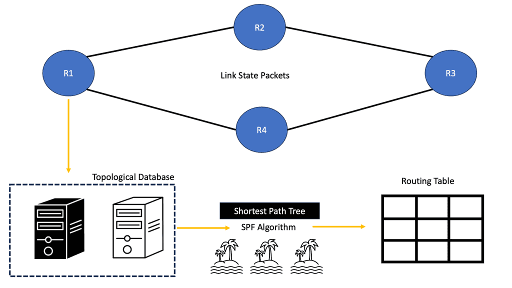
Each connected and directly connected router advertises the link state and metric in link-state dynamic IP routing protocols. Enterprise and service provider networks commonly use OSPF and IS-IS link-state routing protocols. IS-IS advertisements are called link-state packets (LSPs), while OSPF advertisements are called link-state advertisements (LSAs).
Whenever a router receives an advertisement from a neighbor, it stores the information in a local link-state database (LSDB) and advertises it to all of its neighbors. As advertised by the originating router, link-state information is essentially flooded throughout the network unchanged. A synchronized and identical map of the network is provided to all routers in the network.
Datagram networks
Datagram networks are similar to postal networks. Letters sent between people do not require a connection beforehand. Instead, they can provide their address information by dropping the note off at the local post office. A letter is sent to another post office closer to the destination by the post office. The letter traverses a set of post offices to reach the local post office.
A packet in a datagram network includes the source and destination addresses. Packets are sent to the nearest network device, which passes them on to a device closer to the destination. Network devices make routing decisions, also known as forwarding decisions when they receive packets. This can be determined using the packet’s destination address and routing table. Each intermediate device decides for each packet.
IP Forwarding and NAT
In addition to interconnecting networks, IP forwarding enables network address translation (NAT). NAT allows multiple devices within a private network to share a single public IP address. When a device from the private network sends an IP packet to the internet, the router performing NAT modifies the packet’s source IP address to the public IP address before forwarding it. This allows the device to communicate with the internet using a single public IP address, effectively hiding the internal network structure.
Related: Before you proceed, you may find the following post helpful for pre-information:
- OpenFlow protocol
- What is OpenFlow
- Data Center Performance
- Dead Peer Detection
- Network Connectivity
- Computer Networking
IP Forwarding Example. Key What is IP Forwarding Discussion points: |
|
Basics: IP forwarding with an IP Forwarding example
IP routing is the process by which routers forward IP packets. Routers have to take different steps when forwarding IP packets from one interface to another, which has nothing to do with the “learning” of network routes via static or dynamic routing protocols.
Key Points on Default Gateway
Default gateways are used by hosts to reach destinations outside their networks. Default gateways are routers or multilayer switches (switches that can do routing).
When it wants to send something to another host, a host checks whether the destination is within or outside its network. When in the same network, it uses address resolution protocol (ARP) to determine the destination’s MAC address and can then send IP packets. What is the host’s method for checking whether the destination belongs to the same network? Subnet masks are used for this purpose.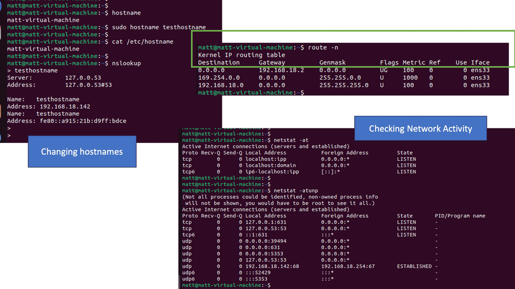
Analysis:
Netstat is a versatile utility used across different operating systems, including Windows, macOS, and Linux. It lets users view active network connections, monitor traffic, and troubleshoot network issues.
The netstat command generates displays that show network status and protocol statistics. You can display the status of TCP and UDP endpoints in table format, routing table information, and interface information.
Netstat offers a wide range of commands that can be utilized to gather specific information. Let’s take a look at some commonly used netstat commands:
- netstat -a: This command displays all active connections and listening ports on the system, providing valuable insights into network activities.
- netstat -r: This command lets users view the system’s routing table, which shows the paths that network traffic takes to reach its destination. This information is crucial for network troubleshooting and optimization.
- netstat -n: This command instructs netstat to display numerical IP addresses and port numbers instead of resolving them to hostnames. It can help identify network performance issues and potential security risks.
Advanced Netstat Techniques
Netstat goes beyond essential network monitoring. Here are a few advanced techniques that can further enhance its utility:
- netstat -p: This command allows users to view the specific process or application associated with each network connection. Administrators can identify potential bottlenecks and optimize system performance by knowing which processes are utilizing network resources.
- netstat -s: By using this command, users can access detailed statistics about various network protocols, including TCP, UDP, and ICMP. These statistics provide valuable insights into network utilization and can aid in troubleshooting network-related issues.
IP Forwarding
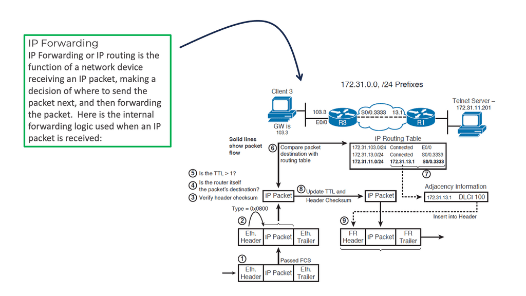
Before you get into the details, let me cover the basics. A router receives a packet on one of its interfaces and then forwards the packet out of another based on the contents found in the IP header. For example, if the packet were part of a video stream ( Multicast / multi-destination), it would be forwarded to multiple interfaces. If the packet were part of a typical banking transaction ( Unicast ), it would be forwarded to one of its interfaces.
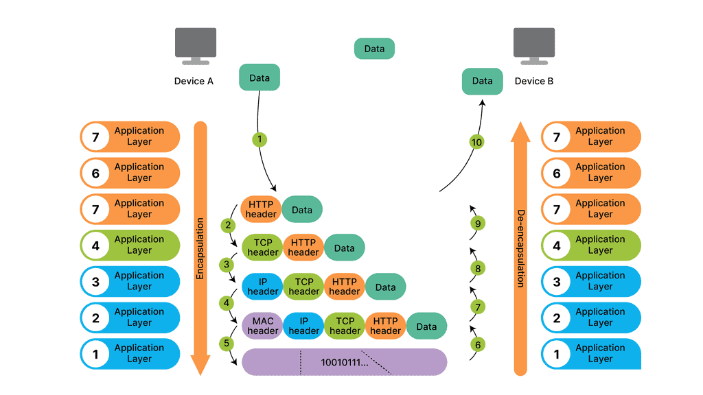
As each routing device forwards the packet hop-by-hop, the packet’s IP header remains relatively unchanged, containing complete instructions for forwarding the packet. However, the data link headers ( the layer directly below ) may change radically at each hop to match the changing media types.
For example, the router receives a packet on one of its attached Ethernet Segments. The routers will first look at the packet’s data-link header, which is Ethernet. If the Ethertype is set to (0x800 ), indicating an IP packet ( A unicast MPLS packet has an Ethertype value of 0x8847 ), the Ethernet header is stripped from the packet, and the IP header is examined.
The “learning” of network routes
IP packet forwarding has nothing to do with the “learning” of network routes carried out through static or dynamic routing protocols. Instead, IP forwarding has everything to do with routers’ steps when they forward an IP packet from one interface to another.
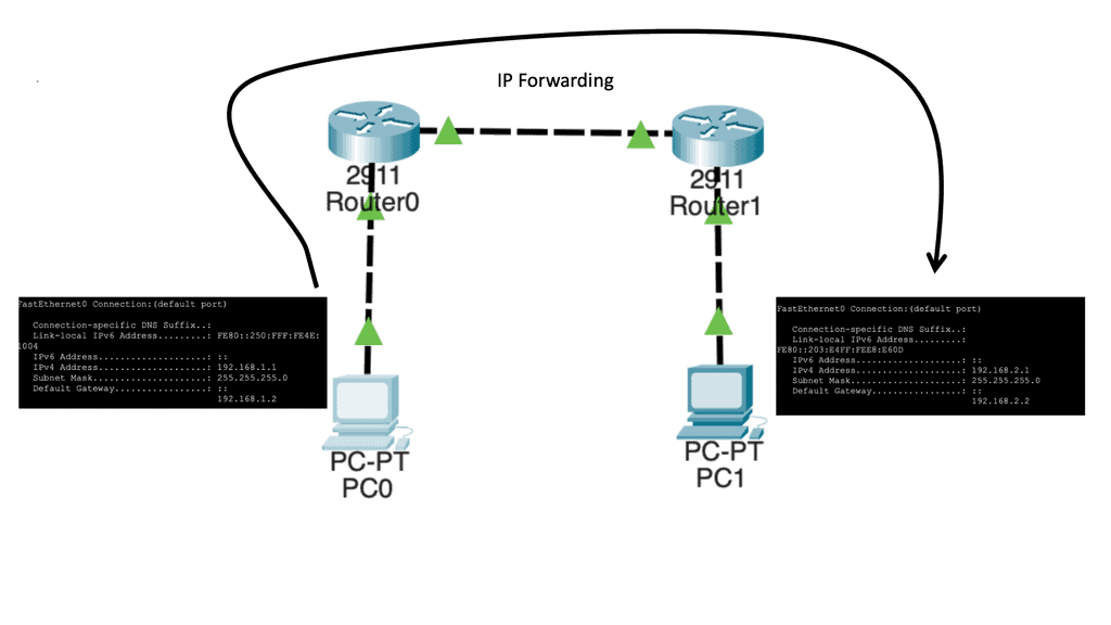
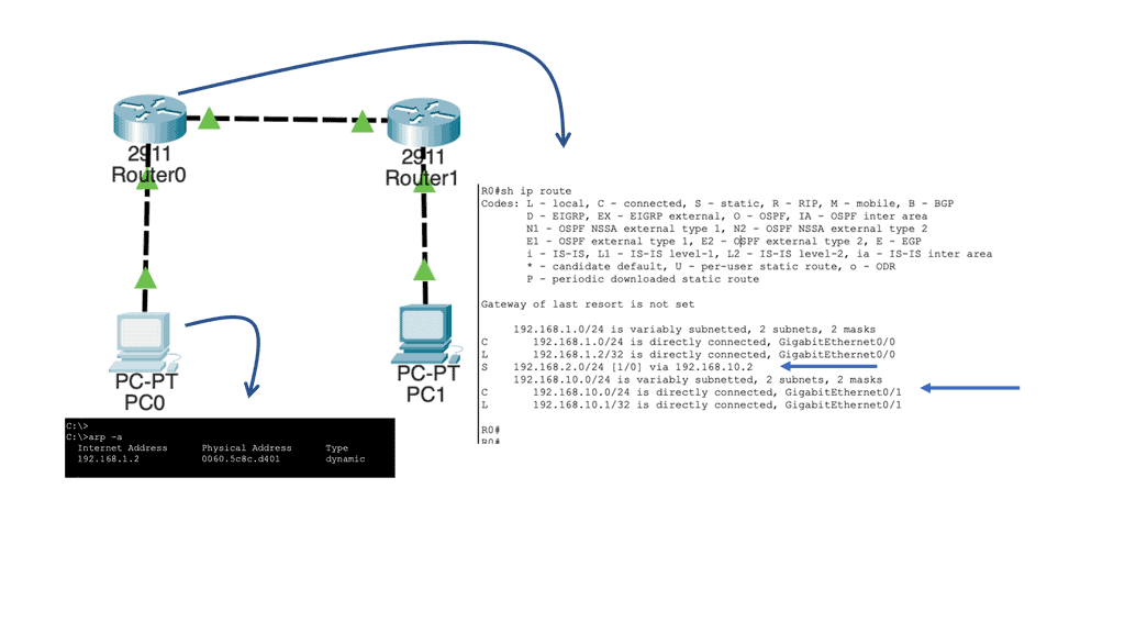
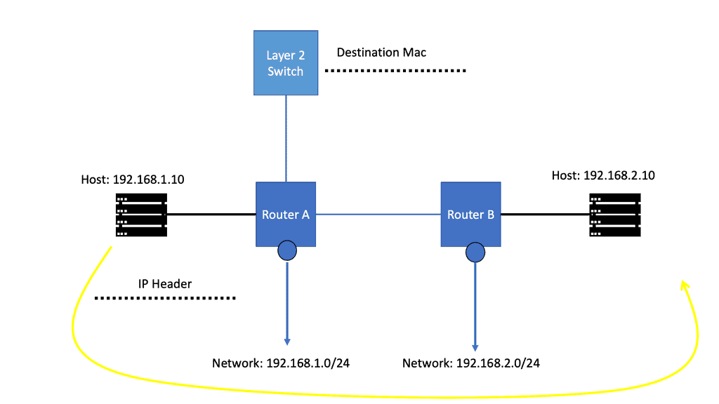
Let us say we have two host computers and two routers. Host1, on the left, will send an IP packet to Host2, which is on the right. This IP packet has to be routed by R0 and R1. Host 1 is on 192.168.1.0/24, and Host 2 is on 192.168.2.0/24
Let’s start with Host1, which creates an IP packet with its IP address (192.168.1.1) as the source and Host 2 (192.168.2.1) as the destination. So the first question that Host1 will need to determine:
- Question: Is the destination I am trying to reach either local or remote?
To get the answers to this question, look at its IP address, subnet mask, and destination IP address.
1st Lab Guide: IP Forwarding
Our network has Host1, which is in network 192.168.1.0/24. As a result, all IP addresses in the 192.168.1.1 – 254 range are local. Unfortunately, our destination (192.168.2.1, which is the remote Host) is outside the local subnet, so we must use the default gateway. In our case, the default gateway is the connected router.
Therefore, Host 1 will build an Ethernet frame and enter its source MAC address. Host 1 then has to ask itself another question. What is the destination MAC address of the default gateway, the connected router?
Analysis:
To determine this, the Host checks its ARP table to find the answer. In our case, Host1 has an ARP entry for 192.168.1.2, the default gateway. It has an ARP entry, as I did a quick testing ping before I took the screenshot. It is a dynamic entry, not a static one, as I did not manually enter this MAC address. If the Host did not have an APR entry, it would have sent an ARP request.
Note:
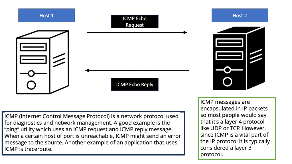
Ping uses the ICMP protocol, and IP uses the network layer (layer 3). Our IP packet will have a source IP address of 192.168.1.1 and a destination IP address of 192.168.1.2. The next step is to put our IP packet in an Ethernet frame, where we set our source MAC address PC0 and destination MAC address PC1.
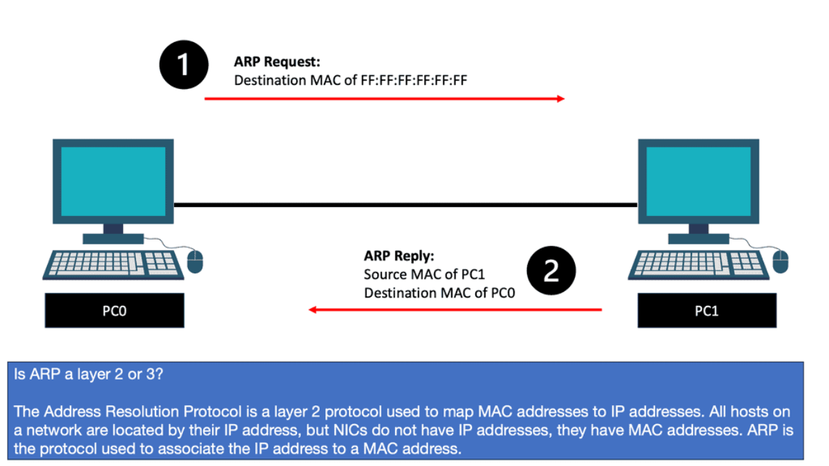
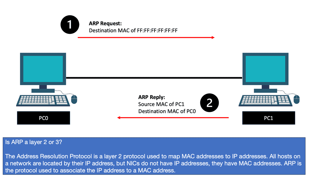
Now, wait a second. How does PC0 know the MAC address of PC1? We know the IP address because we typed it, but H1 cannot identify the MAC address of H2. Another protocol that will solve this problem is ARP (Address Resolution Protocol).
So, with ARP, I have the IP address, and I want to find out the MAC address as we move down the OSI model’s layers so bits can be forwarded on the wire. At this stage, the Ethernet frame carries an IP packet. Then, the frame will be on its way to the directly connected router.
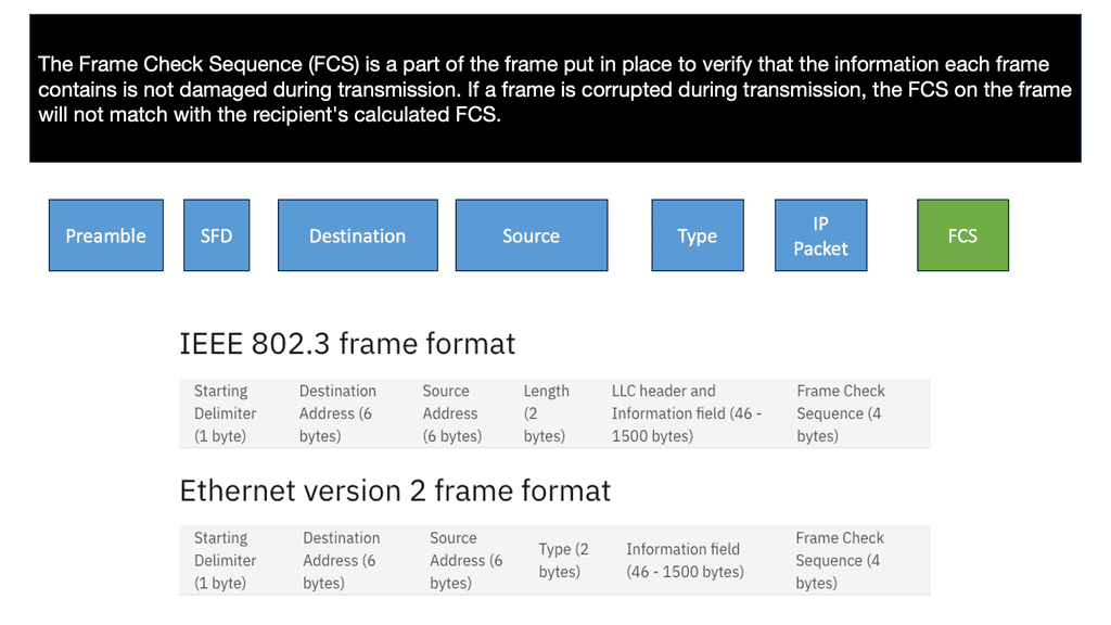
In the network topology at the start of the lab guide, the Ethernet frame makes it to R0. So, as this is a Layer 3 router and not a Host or Layer 2 switch, it has more work. So the first thing it does is check if the FCS (Frame Check Sequence) of the Ethernet frame is correct or not:
If the FCS is incorrect, the frame is dropped right away. Unfortunately, Ethernet has no error recovery; this is done by protocols on upper layers, like TCP on the transport layer.
If the FCS is correct, we will process the frame if:
- The destination MAC address is the address of the router interface.
- The destination MAC address is the subnet’s broadcast address to which the router interface is connected.
- The destination MAC address is a multicast address that the router listens to.
Note:
In our case, the destination MAC address matches the MAC address of R0’s GigabitEthernet 0/0 interface. Therefore, the router will process it. But, first, we de-encapsulate ( which means we will extract) the IP packet out of the Ethernet frame, which is then discarded:
The router, R0, will now look at the IP packet, and the first thing it does is check if the header checksum is OK. Remember that there is also no error recovery on the Layer 3 network layer; we rely on the upper layers. Then R0 checks its routing table to see if there is a match:
Above, you can see that R0 knows how to reach the 192.168.2.0/24 network. This is because the destination address has a next-hop IP address, 192.168.10.2, which is the connecting Router – R1.
It will now do a second routing table lookup to see if it can reach 192.168.10.2. This is called recursive routing. The Recursive Route Lookup follows the same logic of dividing a task into subtasks of the same type. The device repeatedly performs its routing table lookup until it finds the ongoing interface to reach a particular network.
As you can see above, there is an entry for 192.168.10.0/24 with GigabitEthernet 0/1 as the interface. Once this is done, R0 checks its local ARP table to determine if there is an entry for 192.168.10.2. Similar to the sending Host, if there were no ARP entries, R0 would have to send an ARP request to find the MAC address of 192.168.10.2.
The next stage is that R0 builds a new Ethernet frame with its MAC address of the GigabitEthernet 0/1 interface and R1 as the destination. The IP packet is then encapsulated in this new Ethernet frame.
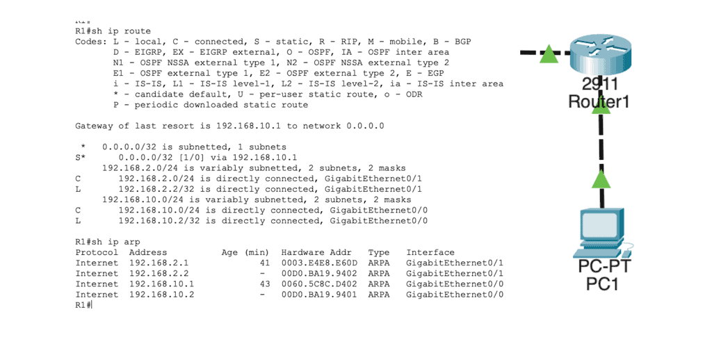
In the routing table, we find this:
Network 192.168.2.0/24 directly connects to R1 on its GigabitEthernet 0/1 interface. R1 will now reduce the TTL of the IP packet from 254 to 253, recalculate the IP header checksum, and check its ARP table to see if it knows how to reach 192.168.2.1. There is an ARP entry there. The new Ethernet frame is created, and the IP packet is encapsulated. Host2 then looks for the protocol field to determine what transport layer protocol we are dealing with; what happens next depends on the protocol used.
Note: The TTL represents a field in IP packets that helps prevent infinite loops and ensures the proper functioning of routing protocols. As a packet traverses through routers, the TTL value gets decremented, and if it reaches zero, the packet is discarded. This mechanism prevents packets from endlessly circulating in a network, facilitating efficient and reliable data transmission.
Knowledge Check: ICMP ( Internet Control Message Protocol )
What is ICMP?
ICMP is a protocol that operates at the network layer of the Internet Protocol Suite. Its primary purpose is to report and diagnose errors that occur during the transmission of IP packets. ICMP messages are typically generated by network devices, such as routers or hosts, to communicate vital information to other devices in the network.
ICMP Functions and Types
ICMP serves several functions, but its most common use is error reporting. When a network device encounters an issue while transmitting an IP packet, it can use ICMP to send an error message back to the source device. This enables the source device to take appropriate action, such as retransmitting the packet or choosing an alternative route.
ICMP messages come in different types, each serving a specific purpose. Some commonly encountered ICMP message types include Destination Unreachable, Time Exceeded, Echo Request, and Echo Reply. Each type has its unique code and is crucial in maintaining network connectivity.
ICMP and Network Troubleshooting
ICMP is an invaluable tool for network troubleshooting. Providing error reporting and diagnostic capabilities helps network administrators identify and resolve network issues more efficiently. ICMP’s ping utility, for example, allows administrators to test a remote host’s reachability and round-trip time. Traceroute, another ICMP-based tool, helps identify the path packets take from the source to the destination.
ICMP and Network Security
While ICMP serves critical networking functions, it is not without its security implications. Certain ICMP message types, such as ICMP Echo Request (ping), can be abused by malicious actors for reconnaissance or denial-of-service attacks. Network administrators often implement security measures, such as ICMP rate limiting or firewall rules, to mitigate potential risks associated with ICMP-based attacks.
Lab Guide: EIGRP and the Variance Command
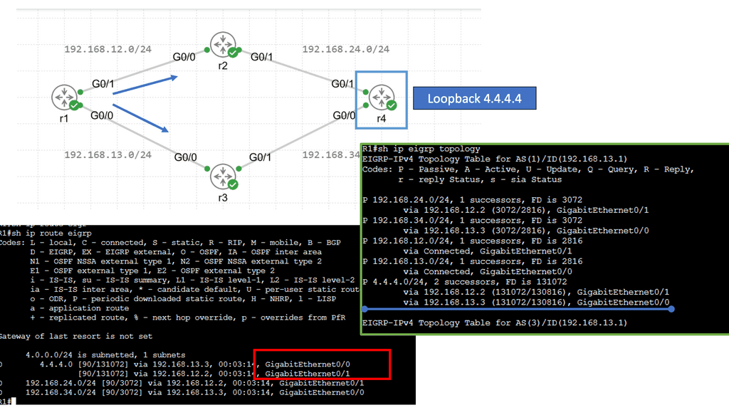
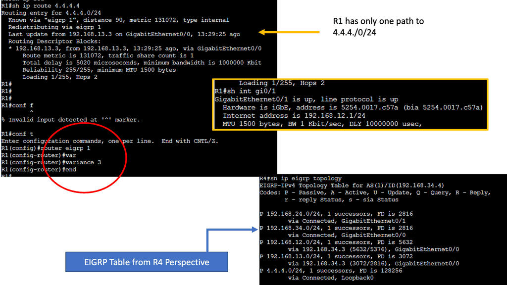
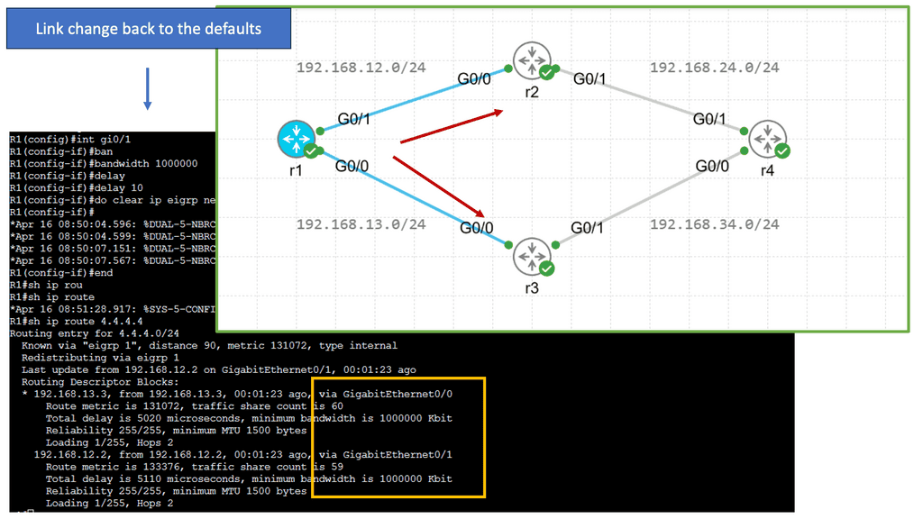
EIGRP operates at the network layer and uses a distance-vector routing algorithm. It is designed to exchange routing information efficiently, calculate the best paths, and adapt to network changes. Cisco EIGRP offers a range of advanced features that can enhance network performance and scalability. We will explore features such as route redistribution, load balancing, and stub routing. In this guide, I will look at the EIGRP variance feature. Below, I have 4 routers. I have changed the bandwidth and delay. Once changed, the routing table only shows one path to the 4.4.4.4 loopback connected to R4.
Understanding EIGRP Variance
EIGRP, or Enhanced Interior Gateway Routing Protocol, is a dynamic routing protocol widely used in enterprise networks. By default, EIGRP only allows load balancing across equal-cost paths. However, in scenarios where multiple paths have varying costs, the EIGRP variance command comes to the rescue. It enables load balancing across unequal-cost paths, distributing traffic more efficiently and effectively.
Configuring EIGRP Variance
Configuring the EIGRP variance command is relatively straightforward. First, you need to access the router’s command-line interface. Once there, you can enter the global configuration mode and specify the variance value. The variance value represents the multiplier determining the feasibility condition for unequal-cost load balancing. For instance, a variance of 2 means that a path with a metric up to two times the best path metric is considered feasible.
Impact on Network Performance
The EIGRP variance command significantly impacts network performance. It effectively utilizes network resources and improves overall throughput by allowing load balancing across unequal-cost paths. Additionally, it enhances network resilience by providing alternative paths in case of link failures. However, it’s important to note that deploying the EIGRP variance command requires careful consideration of network topology and link costs to ensure optimal results.
Inter-network packet transfer
IP forwarding is used for inter-network packet transfer and not for inter-interface transfers. Therefore, if two interfaces are on the same network, we don’t need to enable IP forwarding.
Let us look at an example of IP forwarding. Consider a server with two physical ethernet ports, such as your internal network and the outside world, as a DSL modem provides. The system can communicate on either network if you connect and configure those two interfaces. However, packets from one network cannot travel to another if forwarding is not enabled.
IP forwarding determines which path a packet or datagram can be sent. The process uses routing information to make decisions and is designed to send a packet over multiple networks. Generally, networks are separated from each other by routers.
IP Forwarding Example: Verifying the IP Header
The router then verifies the IP header’s contents by checking several fields to validate it. In addition, the router should check that the entire packet has been received by checking the IP length against the size of the received Ethernet packet. If these basic checks fail, the packet is deemed malformed and discarded.
Next, the router verifies the TTL field in the IP header and determines that it is greater than 1. The Time-To-Live field ( TTL ) specifies how long the packet should live, and its value is counted in terms of the number of routers the packet ( technically a datagram ) has traversed ( hop count ).
IP Forwarding Example: The TTL values
The source host selects the initial TTL value and is recommended to use 64. In specific scenarios, other values are set to limit the time, in hops, that the packet should live. The TTL aims to ensure the packet does not circulate forever when there are routing loops. Each router in the path decrements the TTL field by 1 when it forwards the packet out of its interface (s). When the TTL field is decremented to 0, the packet is discarded, and a message known as an ICMP ( Internet Control Message Protocol ) TTL Exceeded is sent back to the host.
IP Forwarding Example: Checking the Destination
For IP forwarding, the router then looks at the destination IP address, which can be either a destination host ( Unicast ), a group of destination hosts ( multicast ), or all hosts on the segment ( broadcast ). As mentioned previously, the router has what is known as a routing table, which tells it how to forward a packet, and the destination IP address is a crucial component for the routing table lookup.
Forwarding is done on a destination base; if I want to get to destination X, I must go to Y ( the source routing concept is not in this article’s scope). The contents of the router routing table are parsed, and the best-matching routing table entry is returned, indicating whether to forward the packet and, if so, the interface to forward the packet out of and the IP address of the following IP router ( if any ) in the packet’s path.
The CEF process
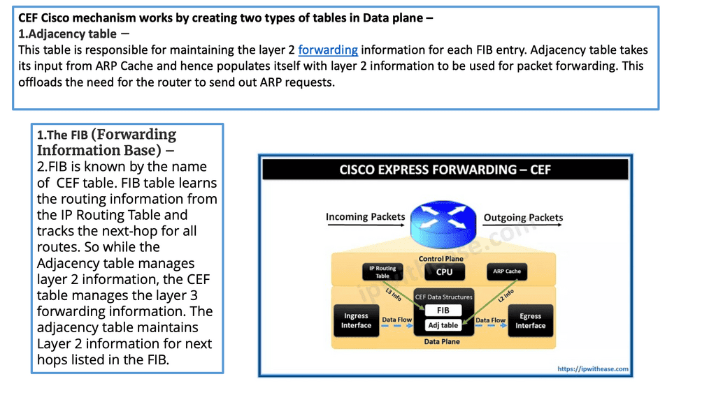
CEFs (Cisco Express Forwarding) are packet-switching technology in Cisco routers. It is designed to enhance network forwarding performance by reducing the overhead associated with Layer 3 forwarding. CEF utilizes a Forwarding Information Base (FIB) and an adjacency table to forward packets quickly to their destinations.
The FIB Table
The FIB maintains a list of all known IP prefixes and their associated next-hop addresses. The adjacency table holds information about the Layer 2 addresses of directly connected neighbors. When a packet arrives at a router, the CEF algorithm consults the FIB to determine the appropriate next-hop address. Then, it uses the adjacency table to forward the packet to the correct interface.
On a Cisco device, the actual moving of the packet from the inbound interface to the outbound interface is carried out by a process known as CEF ( Cisco Express Forwarding ). CEF is a mirror image of the routing table, and any changes in the routing table are reflected in the CEF table. It has a structure different from the routing table, allowing fast lookups.
If you want to parse the routing table, you have to start at the top and work your way down; this can be time-consuming and resource-intensive, especially if your match is the last entry in the routing table. CEF structures let you search on the bit boundary and optimize the routing process with the adjacency table.
2nd Lab Guide: CEF Operations
In this lab guide, I will address CEF operations. There are different switching methods to forward IP packets. Here are the different switching options: Remember that the default is CEF.
- Process switching:
- The CPU examines all packets, and all forwarding decisions are made in software…very slow!
- Fast switching (also known as route caching):
- The CPU examines the first packet in a flow; the forwarding decision is cached in hardware for the next packets in the same flow. This is a faster method.
- (CEF) Cisco Express Forwarding (also known as topology-based switching):
- Forwarding table created in hardware beforehand. All packets will be switched using hardware. This is the fastest method, but it has some limitations. Multilayer switches and routers use CEF.
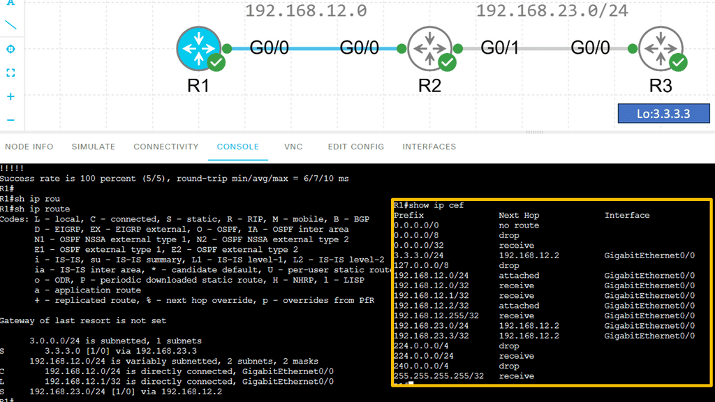
For example, a multilayer switch will use the information from tables built by the (control plane) to build hardware tables. It will use the routing table to construct the FIB (Forwarding Information Base) and the ARP table to create the adjacency table. This is the fastest switching method because we now have all the layer two and three information required to forward IP packets in hardware.
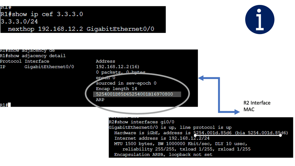
Below are three routers and I, using static routing for complete reachability. On R1, let’s look at the routing and CEF tables. Let’s take a detailed look at the entry for network 3.3.3.0 /24:
Note:
How Cisco Express Forwarding Works
CEF builds and maintains two key data structures: the FIB and Adjacency Table. The FIB contains information about the best path to forward packets, while the Adjacency Table stores Layer 2 next-hop addresses. These data structures enable CEF to make forwarding decisions quickly and efficiently, resulting in faster packet processing.
Advanced Features and Customization Options
Cisco Express Forwarding offers various advanced features and customization options to meet specific networking requirements. These include features like NetFlow, which provides detailed traffic analysis, and load-balancing algorithms allowing intelligent traffic distribution. Administrators can tailor CEF to optimize network performance and adapt to changing traffic patterns.
Understanding the MTU
Suppose a router receives a unicast packet too large to be sent out in one piece, as its length exceeds the outgoing interface’s Maximum Transmission Unit ( MTU ). In that case, the router attempts to split the packet into several smaller pieces called fragments. The difference between IPv4 and IPv6 fragmentation is considerable. Slicing packets into smaller packets adversely affects performance and should be avoided.
One way to avoid fragmentation is to have the exact MTU on all links and have the hosts send a packet with an MTU within this range. However, this may not be possible due to the variety of mediums and administrative domains a packet may take from source to destination. Path MTU discovery ( PMTUD ) is the mechanism used to determine the maximum size of the MTU in the path between two end nodes ( source and destination ).
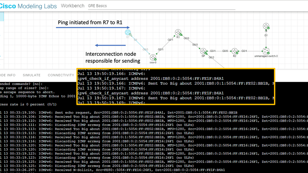
PMTUD
PMTUD dynamically determines the lowest MTU of each link between the end nodes. A host sends an initial packet ( datagram ) with the size of an MTU for that interface, with the DF ( don’t fragment ) bit set.
Any router in the path with a lower MTU discards the packet and returns an ICMP ( Type 4—fragmentation needed and DF set) to the source. This message is also known as a “packet too big” message. The sender estimates a new size for the packet, and the process continues until the PMTU is found.
IP Forwarding Example: Modifying the IP Forwarding
The basics of IP forwarding can be modified in several ways, resulting in data packets taking different paths through the network, some of which are triggered by routing convergence. In previous examples, we discussed routers consulting their routing tables to determine the next hop and single exit interface to send a packet to its destination – “destination-based forwarding. ” However, a router may have multiple paths ( exit interface ) to reach a destination.
These paths can then spread traffic to a destination prefix across alternative links, called multipath routing or load balancing, resulting in more bandwidth available for traffic to that destination.
In a layer three environment, links with the exact cost are considered for equal-cost multipathing and can load balance traffic across those links. You can, however, have unequal cost links ( links with different costs ) used for multipathing, but this needs to be supported in the forwarding routing protocol, e.g., EIGRP.
However, the method used equal or unequal cost multipathing when multiple paths to a destination prefix were used; the router routing table lookup would return numerous next hops. Using the virtual overlay network, we have the underlay and overlay concept for additional abstracts. They are commonly seen in the Layer-3 data center.
IP Forwarding Example: TCP performance
Generally, routers want to guarantee that packets belonging to a given TCP connection always travel the same path. Reordering the TCP packets would reduce TCP performance and increase CPU cycles if done in software. For this reason, routers use a hash function of some TCP connection identifiers ( source and destination IP address ) to choose among the multiple next hops. A TCP connection is identified by a 5-tuple, which refers to a set of five values that comprise a TCP/IP connection.
It includes a source IP address/port range, destination IP address/port number, and the protocol in use. A router can load on any of these. In addition, recent availing technologies let L2 load balance ( ECMP ), such as THRILL and Cisco FabricPath, allow you to build massive data center topologies with Layer 2 multipathing. These data centers often operate under a spine-leaf architecture.
IP options
An application can also modify the handling of its packets by extending the IP headers with one or more IP options. IP options are generally used to aid in statistic collection (route record and timestamp) and not to influence path determination as they offer a performance hit. The Internet routers are already optimized for packet forwarding without additional options.
Security devices or filters implemented on routers generally block strict-source and loose-source routes that can be used to control the path packets take. The router then prepends the appropriate data-link header for its outgoing interface. The ARP process then resolves the next-hop IP to the data-link address ( MAC address ), and the router sends the packet to the next hop, where the process is repeated.
A keynote: Ethernet frames have an L2 identifier known as a MAC address, which has 6 bytes for the destination address and 6 bytes for the source address.
The ARP Process
The ARP process is straightforward, translating the IP address ( L3 ) into the associated MAC addresses ( L2 ). Consider the communication between two hosts on an Ethernet segment: Host 1 has an IP address of 10.10.10.1, and Host 2 has an IP address of 10.10.10.2.
For these hosts to communicate, they must build frames at L2 with source and destination hardware MAC addresses. Host 1 opens a web browser and tries to connect to a service on host 2, which has a destination of 10.10.10.2. Host 1 uses ARP to map the IP address to the MAC address of the destination host.
|
The ARP Table
The ARP tables optimize communications between directly connected devices. Upon receiving an ARP response, devices keep the IP-to-MAC address mapping for some time, usually up to 4 hours. This means a router does not need to send an ARP request for any IP address previously learned. ARP tables may also be updated by what is known as a gratuitous ARP. A gratuitous ARP is an ARP request that a host sends to itself to update its neighbors’ ARP tables.
An example is when a VM is moved from one ESX host to another. For the other devices to know it has moved, it sends a gratuitous ARP. This process updates the router’s ARP table. Due to ARP’s simplistic approach to operation, Layer 2 attacks can exploit its vulnerability.
ARP Security Concerns
One of ARP’s leading security drawbacks is that it does not provide any control that proves that a particular MAC address corresponds to a given IP address. An attacker can exploit this by sending a forged ARP reply with its MAC address and the IP address of a default gateway.
When victims update their ARP table with this new entry, they send packets to the attacker’s host instead of the intended gateway. The attacker can then monitor all traffic destined for the default gateway. This is known as ARP spoofing.
While IP forwarding is a fundamental network connectivity component, it also introduces potential security risks. Unauthorized access to an IP forwarding-enabled device can result in traffic interception, redirection, or even denial of service attacks. Therefore, it is crucial to implement proper security measures, such as access control lists (ACLs) and firewalls, to protect against potential threats.
Key IP Forwarding Summary Points: | Main Checklist Points To Consider
|
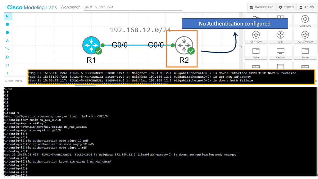
3rd Lab Guide: EIGRP Authentication
Routing Protocol Security
EIGRP authentication is a feature that adds an extra layer of security to network communication. It allows routers to validate the authenticity of the neighboring routers before exchanging routing information. By implementing EIGRP authentication, you can prevent unauthorized devices from participating in the routing process and ensure the integrity of your network.
Note:
Two main components are required to implement EIGRP authentication: a key chain and an authentication algorithm. The key chain contains one or more keys, each with a unique key ID and a corresponding key string. The authentication algorithm, such as MD5 or SHA, generates a message digest based on the key string.
How does authentication benefit us?
- Every routing update packet you receive from your router will be authenticated.
- False routing updates from unapproved sources can be prevented.
- Malicious routing updates should be ignored.
A potential hacker could attempt the following things sitting on your network with a laptop:
- Advertise junk routes in your neighbor adjacency.
- Test whether you can drop the neighbor adjacency of one of your authorized routers by sending malicious packets.
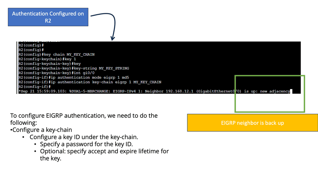
Analysis:
To ensure the success of EIGRP authentication, it is crucial to follow some best practices. These include regularly changing passwords, using complex and unique shared secrets, enabling encryption for password transmission, and monitoring authentication logs for suspicious activity.
Conclusion: EIGRP authentication is an effective means of securing network communication within an enterprise environment. By implementing authentication mechanisms such as simple password authentication or message digest authentication, network administrators can mitigate the risk of unauthorized access and malicious routing information. Remember to carefully configure and manage authentication settings to maintain a robust and secure network infrastructure.
Route Summarization
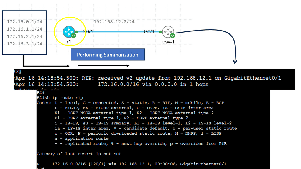
Route summarization involves creating one summary route that represents multiple networks/subnets. Supernetting is also known as route aggregation.
There are several advantages to summarizing:
- Reduces memory requirements by shrinking routing tables.
- We save bandwidth by advertising fewer routes.
- Processing fewer packets and maintaining smaller routing tables saves CPU cycles.
- A flapping network can cause routing tables to become unstable.
Summarizing has some disadvantages as well:
- A router will drop traffic for unused networks without an appropriate destination in the routing table. The summary route may include networks not in use when we use summarization. Routers that have summary routes forward traffic to routers that advertise summary routes.
- The router prefers the path with the longest prefix match. When you use summaries, your router may choose another path where it has learned a more specific network. There is also a single metric for the summary route.
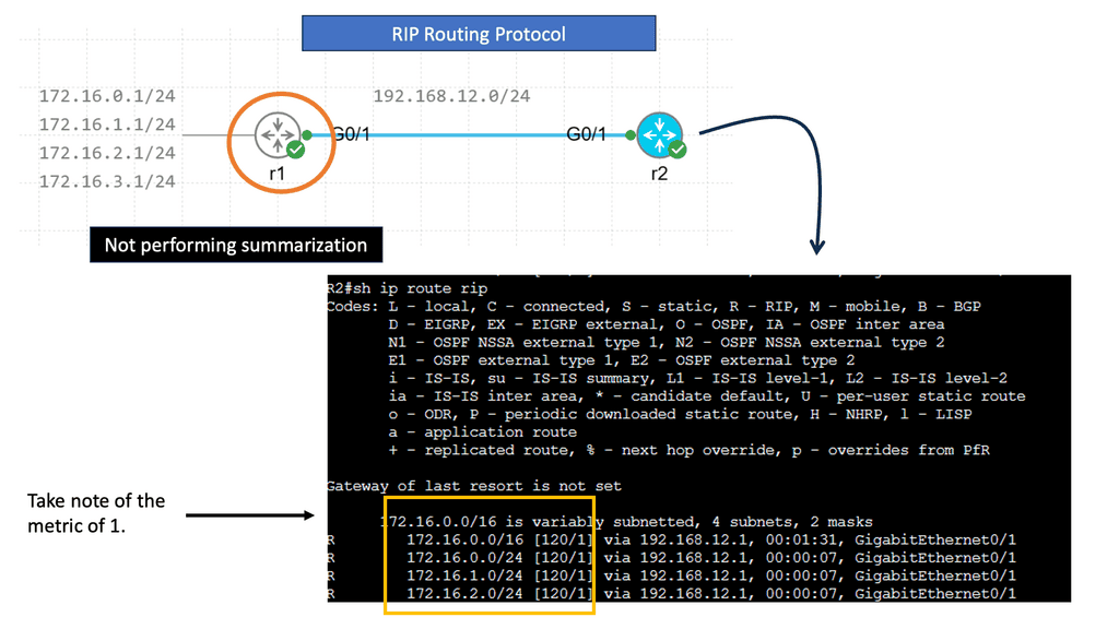
R1 advertises four different networks, and R2 receives them. The more information we advertise, the more bandwidth we require and the more CPU cycles we need to process. Of course, four networks on a Gigabit interface are no problem, but thousands or hundreds of networks are advertised in more extensive networks.
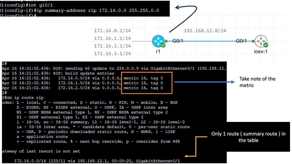
RIP creates a summary entry in the RIP routing database when a summary address is needed in the RIP database. Summary addresses remain in routing databases as long as there are child routes. In addition to removing the last child route, the summary entry is also removed from the database. Because each child route is not listed in an entry, this method of handling database entries reduces the number of entries in the database.
For RIP Version 2 route summarization, the lowest metric of an aggregated entry or the lowest metric of all current child routes must be advertised. For aggregated summarized routes, the best metric should be calculated at route initialization or when metric modifications are made to specific routes at the time of advertisement, not when the aggregated routes are advertised.
Administrative Distance
Suppose a network runs two routing protocols at once, OSPF and EIGRP. R1 receives information from both routing protocols.
- The router should send IP packets using the top path according to EIGRP.
- The router should use the bottom path to send IP packets in OSPF.
What routing information are we going to use? Which one? Do you use OSPF or EIGRP?
When two routing protocols provide information about the same destination network, we must make a choice. You can’t go left and right at the same time. We need to consider AD or administrative distance.
Administrative distance should be as low as possible. Directly connected routes have an AD of 0. Directly connecting it to your router makes sense since nothing is better. Because static routes are configured manually, they have a shallow administrative distance 1. You can sometimes override a routing protocol’s decision with a static route.
Since EIGRP is a Cisco routing protocol, its administrative distance is 90. RIP has 120, while OSPF has 110. Because EIGRP’s AD of 90 is lower than OSPF’s 110, we will use the information EIGRP tells us in the routing table.
Closing Points: IP Forwarding
IP forwarding is crucial in ensuring efficient and reliable data transmission in networking. As a fundamental component of network routing, IP forwarding enables packets of data to be forwarded from one network interface to another, ultimately reaching their intended destination. In this blog post, we delved deeper into IP forwarding, its significance, and its implementation in modern network infrastructures.
IP forwarding, or packet forwarding, refers to direct data packets from one network interface to another based on their destination IP addresses. It is the backbone of network routing, enabling seamless data flow across different networks. IP forwarding is typically performed by routers, specialized network devices designed to route packets between networks efficiently.
IP forwarding is essential in enabling effective communication between devices on different networks. By forwarding packets based on their destination IP addresses, IP forwarding allows data to traverse multiple networks, reaching its intended recipient. This capability is particularly critical in large-scale networks, such as the Internet, where data needs to travel through numerous routers before reaching its final destination.
Implementation of IP Forwarding:
Routers use routing tables to determine the best path for forwarding packets to implement IP forwarding. These routing tables contain a list of network destinations and associated next-hop router addresses. When a router receives a packet, it examines the destination IP address and consults its routing table to determine the appropriate next-hop router for forwarding the packet. This process continues until the packet reaches its final destination.
IP forwarding relies on routing protocols, such as Border Gateway Protocol (BGP) or Open Shortest Path First (OSPF), to exchange routing information between routers. These protocols enable routers to dynamically update their routing tables based on changing network conditions, ensuring packets are forwarded along the most optimal paths.
Summary: IP Forwarding
Section 1: Understanding IP Forwarding
IP forwarding is the fundamental process in which routers and network devices direct incoming packets to their destination. It acts as a traffic cop, intelligently routing data based on network IP addresses. IP forwarding ensures efficient and reliable data transmission by analyzing packet headers and leveraging routing tables.
Section 2: The Benefits of IP Forwarding
2.1 Enhanced Network Efficiency:
IP forwarding optimizes network efficiency by selecting the most efficient path for data transmission. It dynamically adapts to network changes, rerouting packets to avoid congestion and bottlenecks. This results in faster data transfers, reduced latency, and improved overall network performance.
2.2 Scalability and Flexibility:
With IP forwarding, networks can scale effortlessly. It allows for the creation of complex network topologies and the seamless integration of various devices and technologies. Whether connecting local networks or bridging geographically dispersed networks, IP forwarding provides the flexibility needed for modern network infrastructures.
2.3 Secure Communication:
IP forwarding plays a crucial role in securing communication. Incorporating advanced routing protocols and encryption mechanisms ensures the confidentiality and integrity of transmitted data. With IP forwarding, organizations can establish secure virtual private networks (VPNs) and safeguard sensitive information from prying eyes.
Section 3: IP Forwarding in Action
3.1 Enterprise Networks:
IP forwarding is the cornerstone of interconnecting multiple branches, data centers, and remote offices in large-scale enterprise networks. It enables seamless communication and data exchange, facilitating collaboration and enhancing productivity across the organization.
3.2 Internet Service Providers (ISPs):
For ISPs, IP forwarding is the lifeblood of internet connectivity. It allows them to efficiently route traffic between their networks and other ISPs, ensuring uninterrupted internet access for end-users. IP forwarding enables the global interconnectivity we rely on for browsing the web, streaming media, and accessing cloud services.
Conclusion:
In conclusion, IP forwarding is not merely a technical process but a catalyst for seamless connectivity. Its ability to efficiently route data, enhance network performance, and ensure secure communication makes it an indispensable component of modern networking. Whether you’re a network engineer, an IT professional, or a curious technology enthusiast, understanding IP forwarding empowers you to unlock the true potential of interconnected networks.
- DMVPN - May 20, 2023
- Computer Networking: Building a Strong Foundation for Success - April 7, 2023
- eBOOK – SASE Capabilities - April 6, 2023

