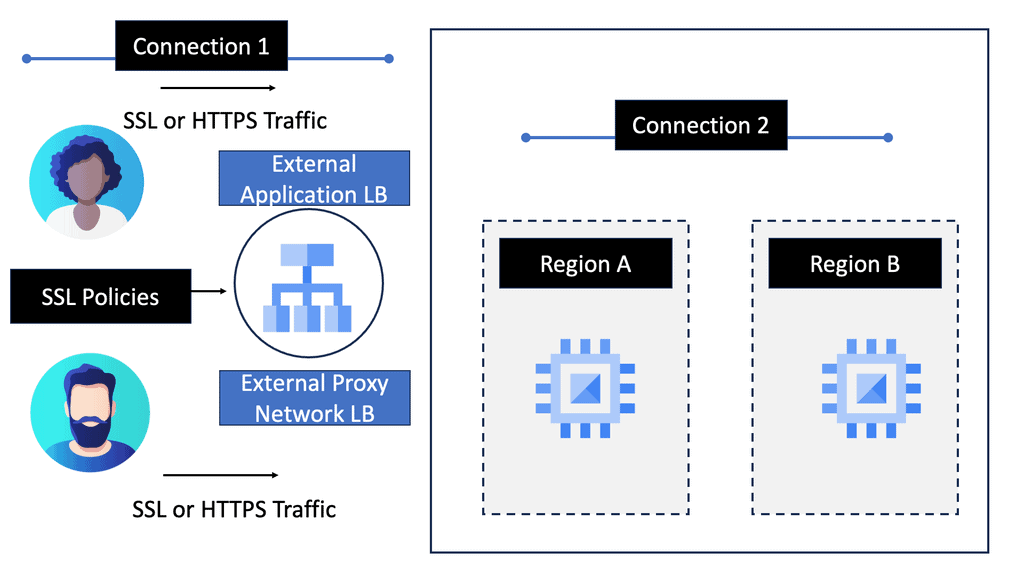
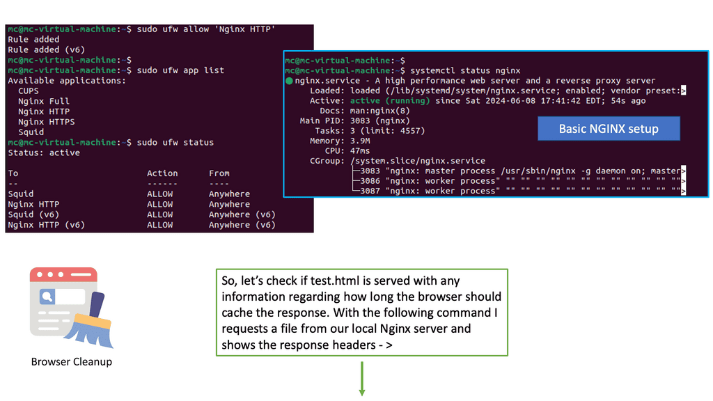
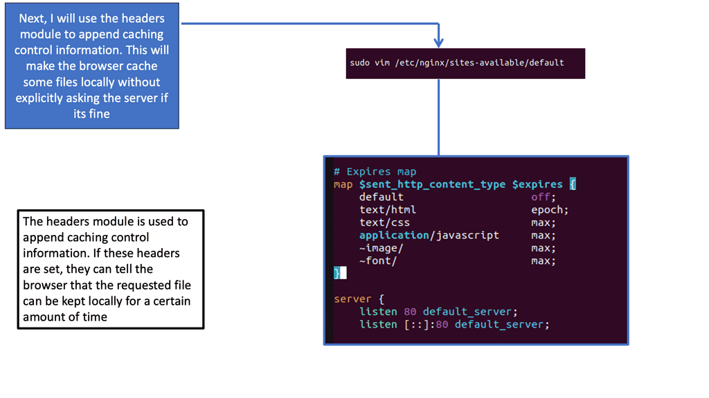
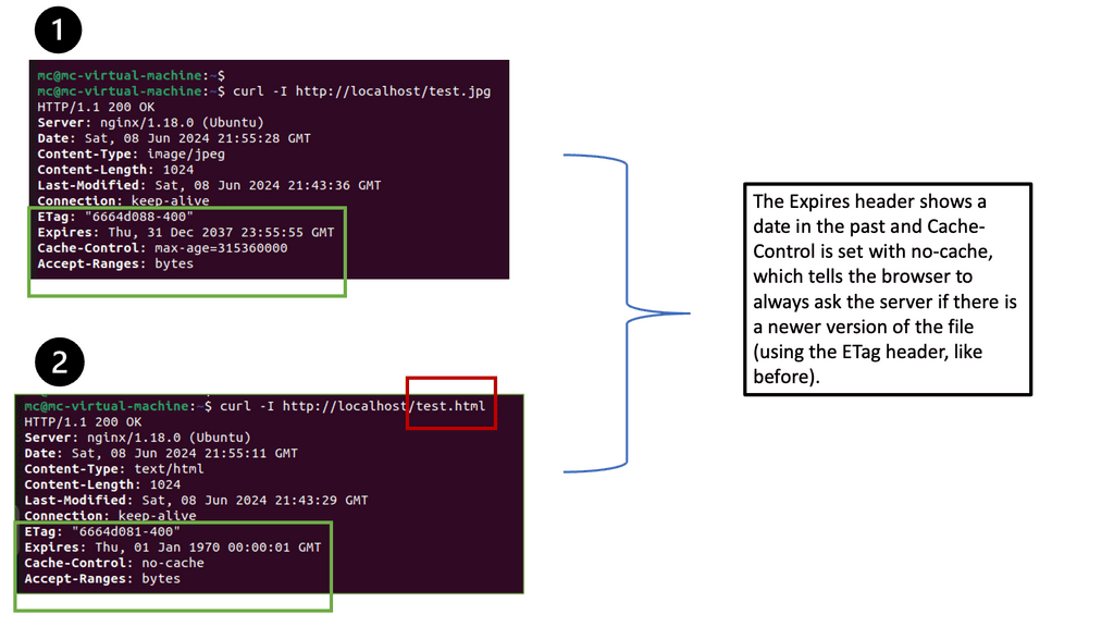
Silver glittering star ornament on wooden background leaving copyspace on the left

Load Balancing

Load Balancing

In today's digital age, where websites and applications are expected to be fast, efficient, and reliable, load balancing has emerged as a critical component of modern computing infrastructure. Load balancing significantly ensures that server resources are utilized optimally, maximizing performance and preventing system failures. This blog post will explore the concept of load balancing, its benefits, and its various techniques.

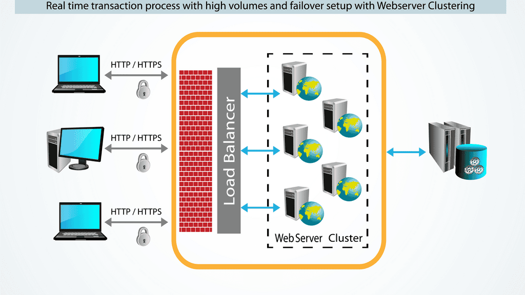
Load balancing evenly distributes incoming network traffic across multiple servers to avoid overburdening any single server. By dynamically allocating client requests, load balancers help ensure that no single server becomes overwhelmed, enhancing the overall performance and availability of the system. This distribution of traffic also helps maintain seamless user experiences during peak usage periods.

Load balancing, at its core, involves distributing incoming network traffic across multiple servers or resources to prevent any single component from becoming overwhelmed. By intelligently managing the workload, load balancing improves resource utilization, enhances scalability, and provides fault tolerance. Whether it's a website, a cloud service, or a complex network infrastructure, load balancing acts as a vital foundation for seamless operations.

Round Robin: The Round Robin method evenly distributes traffic across available servers in a cyclic manner. It ensures that each server gets an equal share of requests, promoting fairness and preventing any single server from being overloaded.

Least Connection: The Least Connection approach directs incoming requests to the server with the fewest active connections. This strategy helps balance the load by distributing traffic based on the current workload of each server, ensuring a more even distribution of requests.

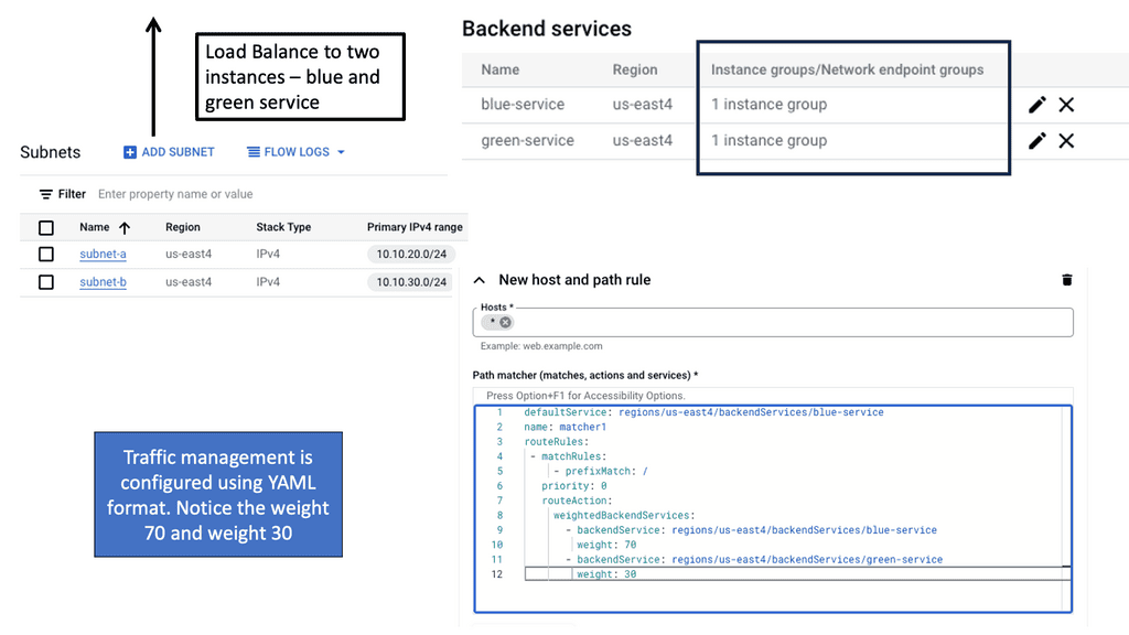
Weighted Round Robin: Weighted Round Robin assigns different weights to servers based on their capacity and performance. Servers with higher weights receive a larger proportion of traffic, allowing for efficient utilization of resources and optimal performance.

Improved Performance: Load balancing ensures that servers or resources are not overwhelmed with excessive traffic, resulting in improved response times and faster processing of requests. This leads to an enhanced user experience and increased customer satisfaction.

Scalability and Flexibility: Load balancing allows for easy scaling of resources by adding or removing servers based on demand. It provides the flexibility to adapt quickly to changing workload conditions, ensuring efficient resource allocation and optimal performance.

High Availability and Fault Tolerance: By distributing traffic across multiple servers, load balancing enhances fault tolerance and minimizes the impact of server failures. If one server becomes unavailable, the load balancer redirects traffic to the remaining servers, ensuring uninterrupted service availability.

Load balancing is a critical component of modern computing, enabling businesses to achieve optimal performance, scalability, and high availability. By intelligently managing network traffic, load balancing ensures efficient resource utilization and enhances the overall user experience. Whether it's a small website or a large-scale cloud infrastructure, implementing a robust load balancing solution is crucial for maintaining seamless operations in today's digital landscape.

Highlights: Load Balancing

– 1: Load balancing evenly distributes incoming network traffic across multiple servers, ensuring no single server is overwhelmed with excessive requests. By intelligently managing the workload, load balancing enhances applications’ or websites’ overall performance and availability. It acts as a traffic cop, directing users to different servers based on various algorithms and factors.

–  2: Load balancing evenly distributes incoming network traffic or computational workload across multiple resources, such as servers, to prevent any single resource from becoming overloaded. By distributing the workload, load balancing ensures that resources are utilized efficiently, minimizing response times and maximizing throughput.

**Types of Load Balancers**

There are several types of load balancers, each with its unique characteristics and advantages. Hardware load balancers are physical devices often used in large-scale data centers. They are known for their robustness and reliability. On the other hand, software load balancers are applications that can be installed on any server, offering flexibility and scalability. Finally, cloud-based load balancers have gained popularity due to their ability to adapt to varying loads and their seamless integration with cloud services.

**Benefits of Implementing Load Balancing**

The advantages of a well-implemented load balancing strategy are manifold. Firstly, it improves the availability and reliability of applications, ensuring that users can access services without interruption. Secondly, it enhances performance by reducing response times and optimizing resource utilization. Lastly, load balancing contributes to security by detecting and mitigating potential threats before they can impact the system.

**Challenges in Load Balancing**

Despite its benefits, load balancing is not without its challenges. Network administrators must carefully configure load balancers to ensure they distribute traffic effectively. Misconfigurations can lead to uneven loads and potential downtimes. Furthermore, as the digital landscape evolves, load balancers must adapt to new technologies and protocols, requiring ongoing maintenance and updates.

Example: Load Balancing with HAProxy

Understanding HAProxy

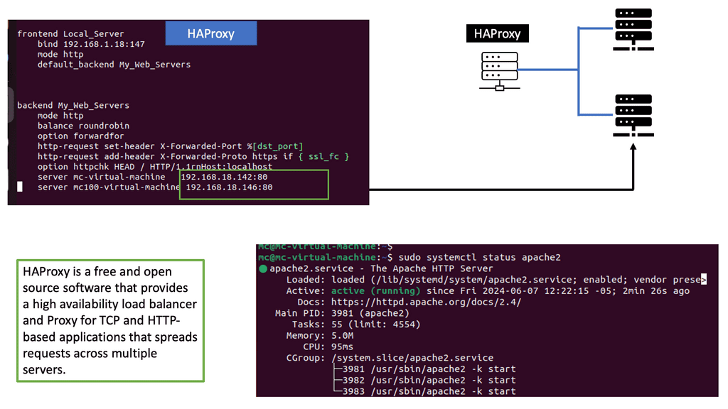
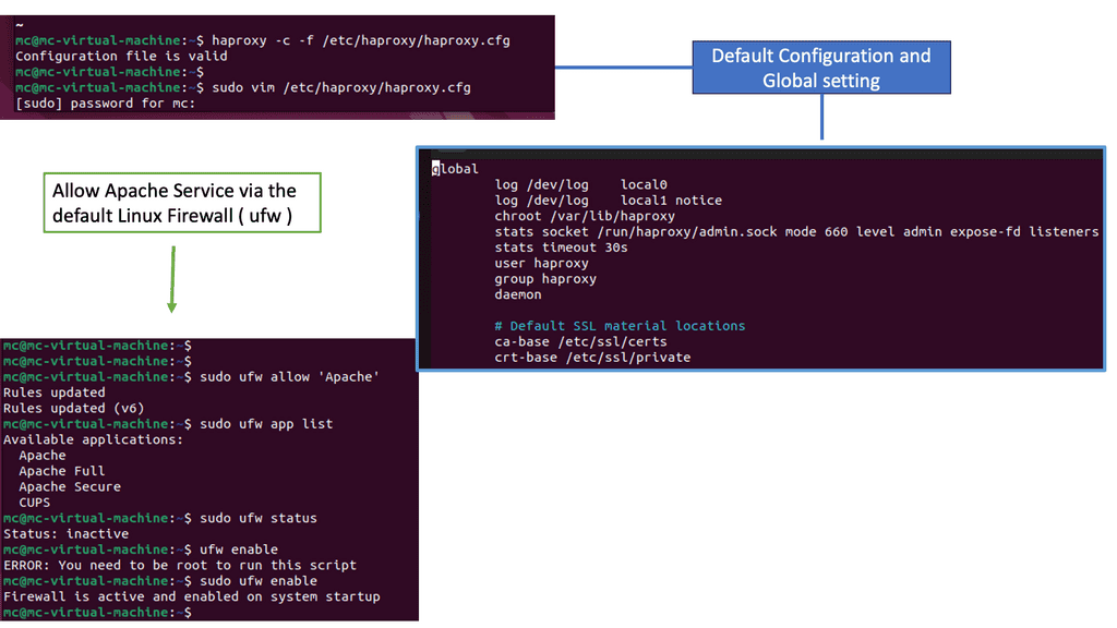
HAProxy, short for High Availability Proxy, is an open-source load balancer and proxy server solution. It acts as an intermediary between clients and servers, distributing incoming requests across multiple backend servers to ensure optimal performance and reliability. With its robust architecture and extensive configuration options, HAProxy is a versatile tool for managing and optimizing web traffic.

HAProxy offers a wide range of features that make it an ideal choice for handling web traffic. Some notable features include:

1. Load Balancing: HAProxy intelligently distributes incoming requests across multiple backend servers, ensuring optimal resource utilization and preventing overload.

2. SSL/TLS Termination: HAProxy can handle SSL/TLS encryption and decryption, offloading the processing burden from backend servers and improving overall performance.

3. Health Checks: HAProxy regularly monitors the health of backend servers, automatically removing or adding them based on their availability, ensuring seamless operation.

4. Content Switching: HAProxy can route requests based on different criteria such as URL, headers, cookies, or any other custom parameters, allowing for advanced content-based routing.

Exploring Scale-Out Architecture

Scale-out architecture, also known as horizontal scaling, involves adding more servers to a system to handle increasing workload. Unlike scale-up architecture, which involves upgrading existing servers, scale-out architecture focuses on expanding the resources horizontally. By distributing the workload across multiple servers, scale-out architecture enhances performance, scalability, and fault tolerance.

To implement load balancing and scale-out architecture, various approaches and technologies are available. One common method is to use a dedicated hardware load balancer, which offers advanced traffic management features and high-performance capabilities. Another option is to utilize software-based load balancing solutions, which can be more cost-effective and provide flexibility in virtualized environments. Additionally, cloud service providers often offer load balancing services as part of their infrastructure offerings.


Example: Understanding Squid Proxy

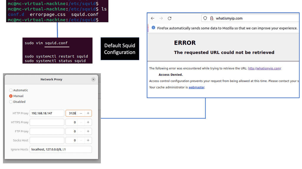
Squid Proxy is a widely used caching and forwarding HTTP web proxy server. It acts as an intermediary between the client and the server, providing enhanced security and performance. By caching frequently accessed web content, Squid Proxy reduces bandwidth usage and accelerates web page loading times.

Bandwidth Optimization: One of the key advantages of Squid Proxy is its ability to optimize bandwidth usage. By caching web content, Squid Proxy reduces the amount of data that needs to be fetched from the server, resulting in faster page loads and reduced bandwidth consumption.

Improved Security: Squid Proxy offers advanced security features, making it an ideal choice for organizations and individuals concerned about online threats. It can filter out malicious content, block access to potentially harmful websites, and enforce user authentication, ensuring a safer browsing experience.

Content Filtering and Access Control: With Squid Proxy, administrators can implement content filtering and access control policies. This allows for fine-grained control over the websites and content that users can access, making it an invaluable tool for parental controls, workplace enforcement, and compliance with regulatory requirements.

Load Balancing Algorithms

Various load-balancing algorithms are employed to distribute traffic effectively. Round Robin, the most common algorithm, cyclically assigns requests to resources sequentially. On the other hand, Weighted Round Robin assigns a higher weight to more powerful resources, enabling them to handle a more significant load. The Least Connections Algorithm also directs requests to the server with the fewest active connections, promoting resource utilization.

  • Round Robin Load Balancing: Round-robin load balancing is a simple yet effective technique in which incoming requests are sequentially distributed across a group of servers. This method ensures that each server receives an equal workload, promoting fairness. However, it does not consider the actual server load or capacity, which can lead to uneven distribution in specific scenarios.
  • Weighted Round Robin Load Balancing: Weighted round-robin load balancing improves the traditional round-robin technique by assigning weights to each server. This allows administrators to allocate more resources to higher-capacity servers, ensuring efficient utilization. By considering server capacities, weighted round-robin load balancing achieves a better distribution of incoming requests.
  • Least Connection Load Balancing: Least connection load balancing dynamically assigns incoming requests to servers with the fewest active connections, ensuring an even workload distribution based on real-time server load. This technique is beneficial when server capacity varies, as it intelligently routes traffic to the least utilized resources, optimizing performance and preventing server overload.
  • Layer 7 Load Balancing: Layer 7 load balancing operates at the application layer of the OSI model, making intelligent routing decisions based on application-specific data. This advanced technique considers factors such as HTTP headers, cookies, or URL paths, allowing for more granular load distribution. Layer 7 load balancing is commonly used in scenarios where different applications or services reside on the same set of servers.

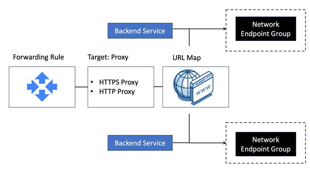
Google Cloud Load Balancing

### Understanding the Basics of NEGs

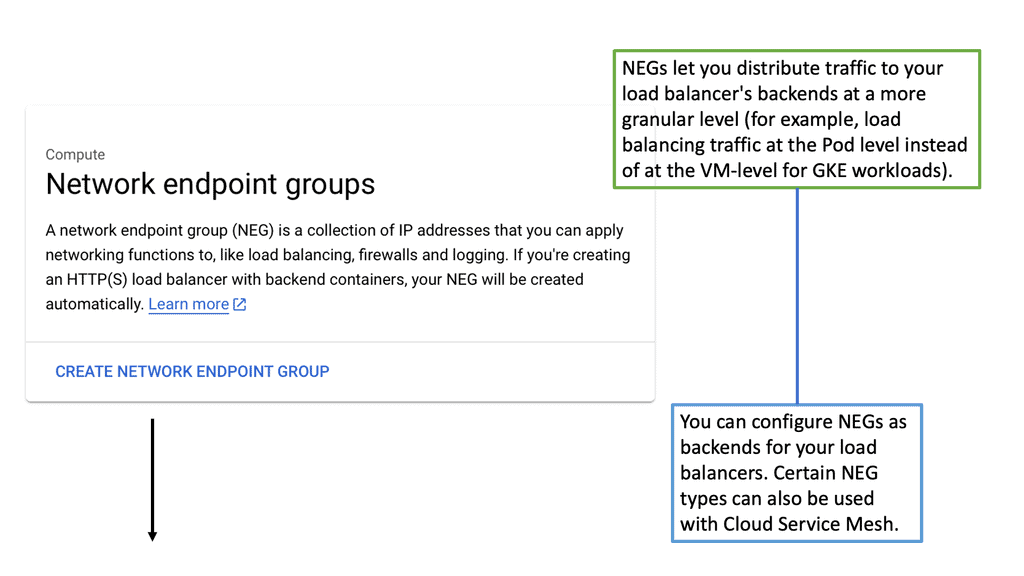
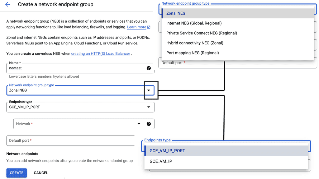
Network Endpoint Groups are essentially collections of IP addresses, ports, and protocols that define how traffic is directed to a set of endpoints. In GCP, NEGs can be either zonal or serverless, each serving a unique purpose. Zonal NEGs are tied to virtual machine (VM) instances within a specific zone, offering a way to manage traffic within a defined geographic area.

On the other hand, serverless NEGs are used to connect to serverless services, such as Cloud Run, App Engine, or Cloud Functions. By categorizing endpoints into groups, NEGs facilitate more granular control over network traffic, allowing for optimized load balancing and resource allocation.

### The Role of NEGs in Load Balancing

One of the primary applications of NEGs is in load balancing, a critical component of network infrastructure that ensures efficient distribution of traffic across multiple servers. In GCP, NEGs enable sophisticated load balancing strategies by allowing users to direct traffic based on endpoint health, proximity, and capacity.

This flexibility ensures that applications remain responsive and resilient, even during peak traffic periods. By integrating NEGs with GCP’s load balancing services, businesses can achieve high availability and low latency, enhancing the user experience and maintaining uptime.

### Leveraging NEGs for Scalability and Flexibility

As businesses grow and evolve, so too do their network requirements. NEGs offer the scalability and flexibility needed to accommodate these changes without significant infrastructure overhauls. Whether expanding into new geographic regions or deploying new applications, NEGs provide a seamless way to integrate new endpoints and manage traffic. This adaptability is particularly beneficial for organizations leveraging hybrid or multi-cloud environments, where the ability to quickly adjust to changing demands is crucial.

### Best Practices for Implementing NEGs

Implementing NEGs effectively requires a thorough understanding of network architecture and strategic planning. To maximize the benefits of NEGs, consider the following best practices:

1. **Assess Traffic Patterns**: Understand your application’s traffic patterns to determine the optimal configuration for your NEGs.

2. **Monitor Endpoint Health**: Regularly monitor the health of endpoints within your NEGs to ensure optimal performance and reliability.

3. **Utilize Automation**: Take advantage of automation tools to manage NEGs and streamline operations, reducing the potential for human error.

4. **Review Security Protocols**: Implement robust security measures to protect the endpoints within your NEGs from potential threats.

By adhering to these practices, organizations can effectively leverage NEGs to enhance their network performance and resilience.

network endpoint groups

Google Managed Instance Groups

### Understanding Managed Instance Groups

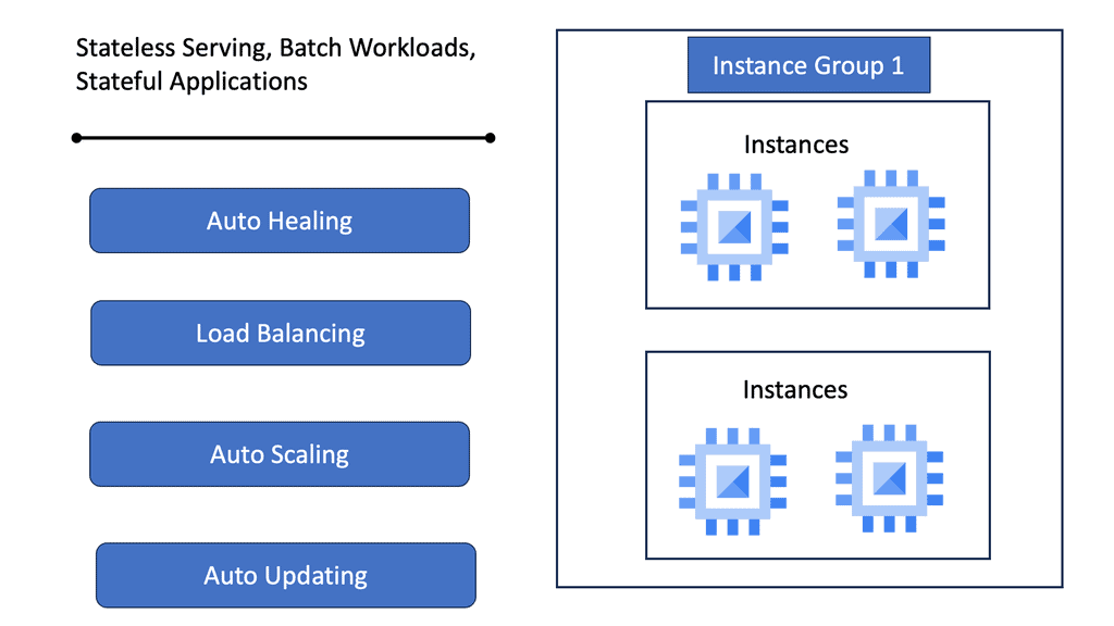
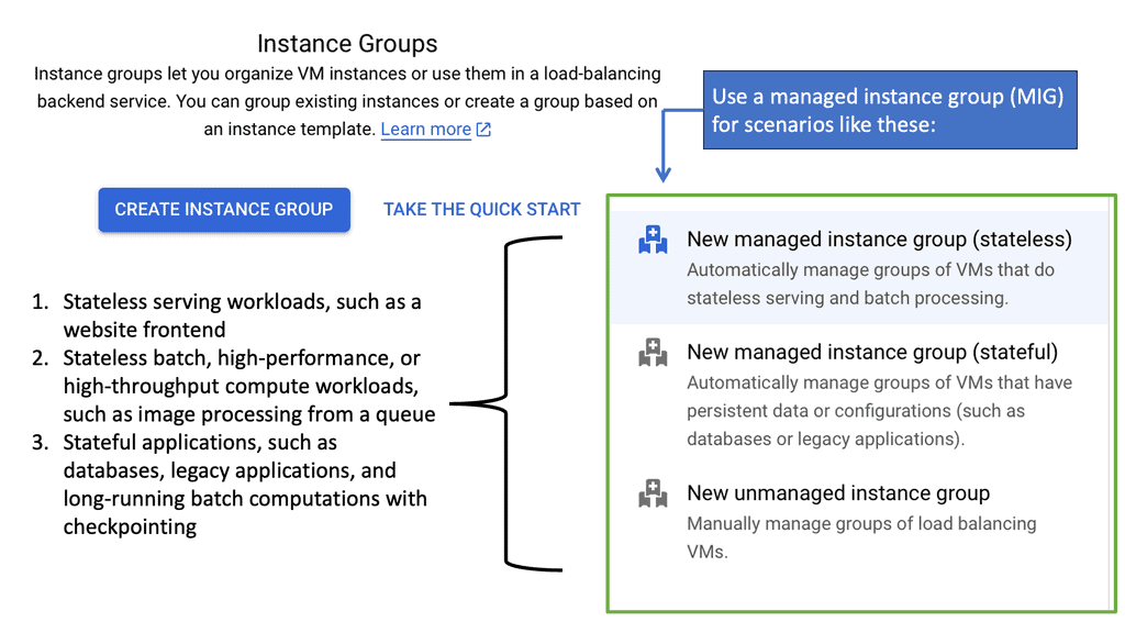
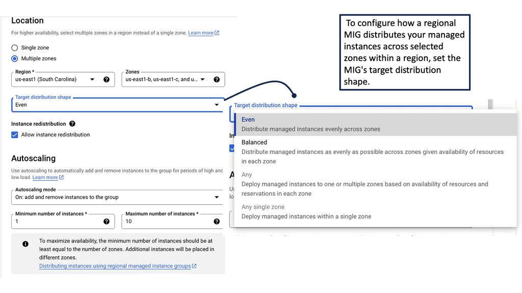
Managed Instance Groups (MIGs) are a powerful feature offered by Google Cloud, designed to simplify the management of virtual machine instances. MIGs allow developers and IT administrators to focus on scaling applications efficiently without getting bogged down by the complexities of individual instance management. By automating the creation, deletion, and management of instances, MIGs ensure that applications remain highly available and responsive to user demand.

### The Benefits of Using Managed Instance Groups

One of the primary advantages of using Managed Instance Groups is their ability to facilitate automated scaling. As your application demands increase or decrease, MIGs can automatically adjust the number of instances running, ensuring optimal performance and cost efficiency. Additionally, MIGs offer self-healing capabilities, automatically replacing unhealthy instances with new ones to maintain the overall integrity of the application. This automation reduces the need for manual intervention and helps maintain service uptime.

### Setting Up Managed Instance Groups on Google Cloud

Getting started with Managed Instance Groups on Google Cloud is straightforward. First, you’ll need to define an instance template, which specifies the configuration for the instances in your group. This includes details such as the machine type, boot disk image, and any startup scripts required. Once your template is ready, you can create a MIG using the Google Cloud Console or gcloud command-line tool, specifying parameters like the desired number of instances and the autoscaling policy.

### Best Practices for Using Managed Instance Groups

To make the most of Managed Instance Groups, it’s important to follow some best practices. Firstly, ensure that your instance templates are up-to-date and optimized for your application’s needs. Secondly, configure health checks to monitor the status of your instances, allowing MIGs to replace any that fail to meet your defined criteria. Lastly, regularly review your autoscaling policies to ensure they align with your application’s usage patterns, preventing unnecessary costs while maintaining performance.

Managed Instance Group

### What are Health Checks?

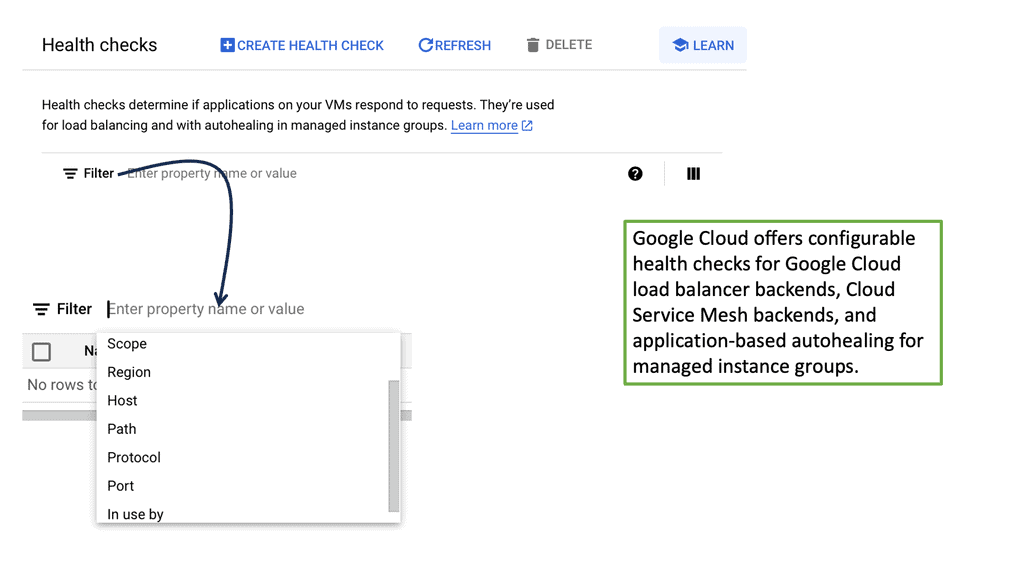
Health checks are automated tests that help determine the status of your servers in a load-balanced environment. These checks monitor the health of each server, ensuring that requests are only sent to servers that are online and functioning correctly. This not only improves the reliability of the application but also enhances user experience by minimizing downtime.

### Google Cloud and Its Approach

Google Cloud offers robust solutions for cloud load balancing, including health checks that are integral to its service. These checks can be configured to suit different needs, ranging from simple HTTP checks to more complex TCP and SSL checks. By leveraging Google Cloud’s health checks, businesses can ensure their applications are resilient and scalable.

### Types of Health Checks

There are several types of health checks available, each serving a specific purpose:

– **HTTP/HTTPS Checks:** These are used to test the availability of web applications. They send HTTP requests to the server and evaluate the response to determine server health.

– **TCP Checks:** These are used to test the connectivity of a server. They establish a TCP connection and check for a successful handshake.

– **SSL Checks:** These are similar to TCP checks but provide an additional layer of security by verifying the SSL handshake.

### Configuring Health Checks in Google Cloud

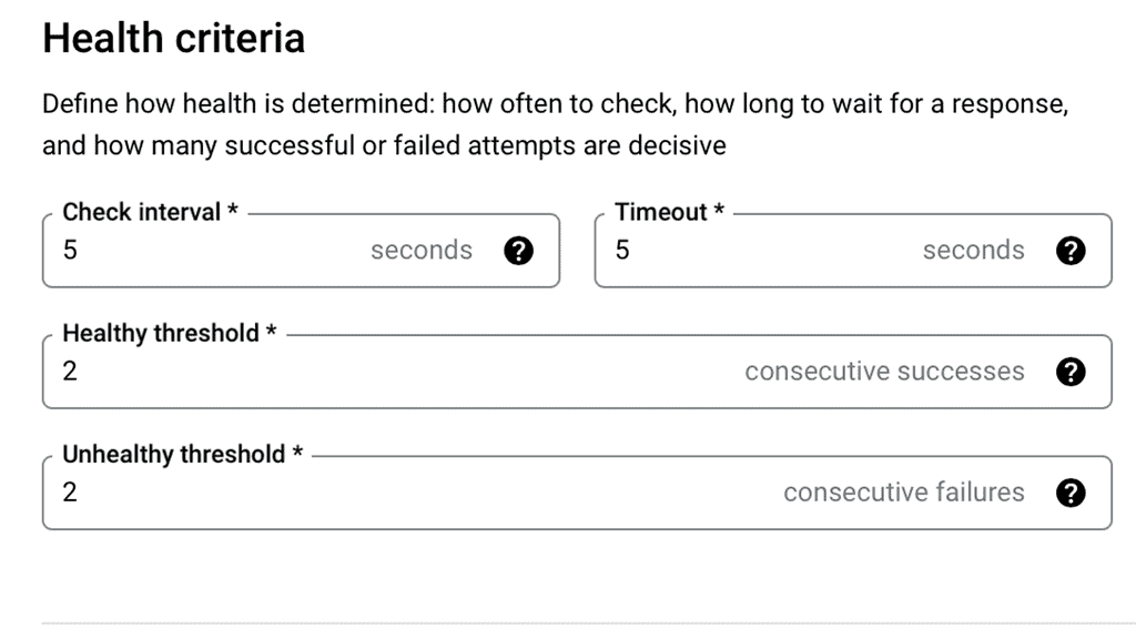
Setting up health checks in Google Cloud is straightforward. Users can access the Google Cloud Console, navigate to the load balancing section, and configure health checks based on their requirements. It’s essential to choose the appropriate type of health check and set parameters such as check interval, timeout, and threshold values to ensure optimal performance.

Cross-Region Load Balancing

Understanding Cross-Region Load Balancing

Cross-region load balancing allows you to direct incoming HTTP requests to the most appropriate server based on various factors such as proximity, server health, and current load. This not only enhances the user experience by reducing latency but also improves the system’s resilience against localized failures. Google Cloud offers powerful tools to set up and manage cross-region load balancing, enabling businesses to serve a global audience efficiently.

## Setting Up Load Balancing on Google Cloud

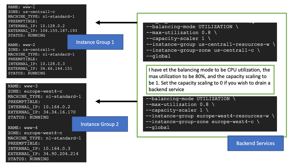
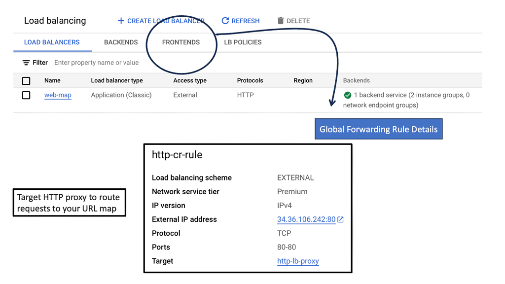
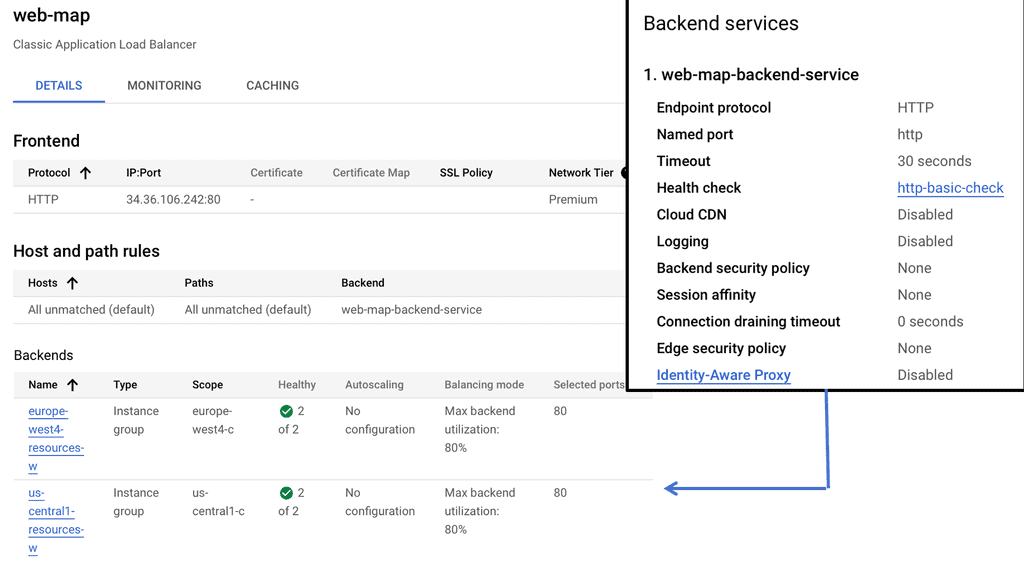
Google Cloud provides a comprehensive load balancing service that supports multiple types of traffic and protocols. To set up cross-region HTTP load balancing, you need to start by defining your backend services and health checks. Next, you configure the frontend and backend configurations, ensuring that your load balancer has the necessary information to route traffic correctly. Google Cloud’s intuitive interface simplifies these steps, allowing you to deploy a load balancer with minimal hassle.

## Best Practices for Effective Load Balancing

When implementing cross-region load balancing, several best practices can help optimize your configuration. Firstly, always use health checks to ensure that traffic is only routed to healthy instances. Additionally, make use of Google’s global network to minimize latency and ensure consistent performance. Regularly monitor your load balancer’s performance metrics to identify potential bottlenecks and adjust configurations as needed.

cross region load balancing

Distributing Load with Cloud CDN

Understanding Cloud CDN

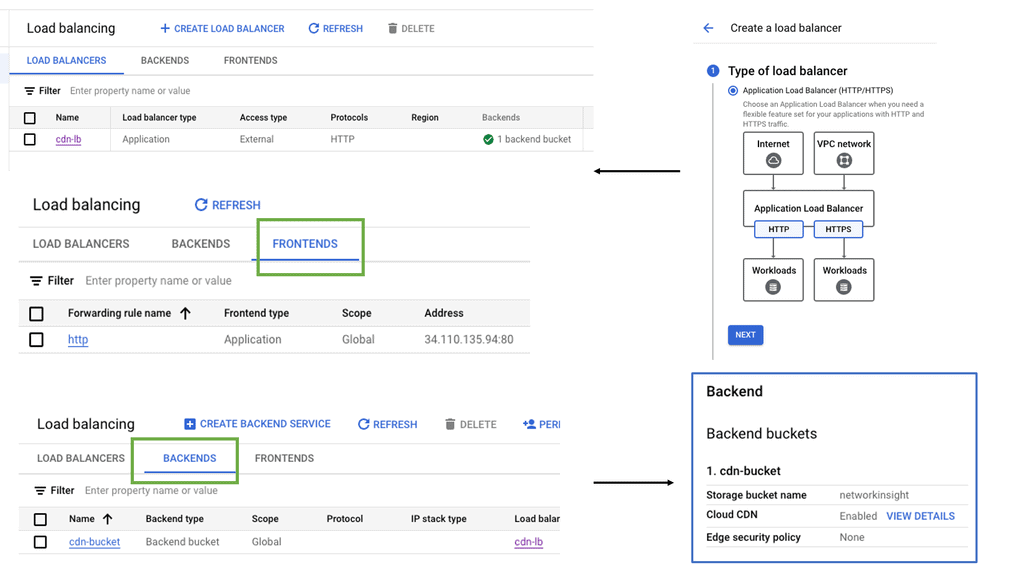
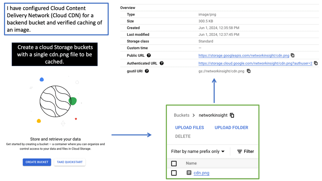
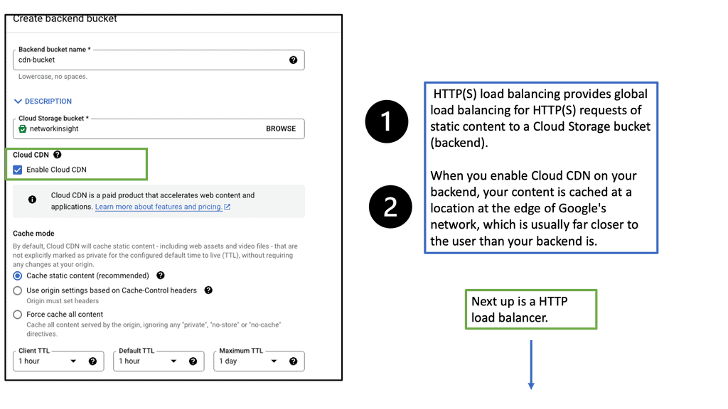
Cloud CDN is a powerful content delivery network offered by Google Cloud Platform. It works by caching your website’s content across a distributed network of servers strategically located worldwide. This ensures that your users can access your website from a server closest to their geographical location, reducing latency and improving overall performance.

Accelerated Content Delivery: By caching static and dynamic content, Cloud CDN reduces the distance between your website and its users, resulting in faster content delivery times. This translates to improved page load speeds, reduced bounce rates, and increased user engagement.

Scalability and Global Reach: Google’s extensive network of CDN edge locations ensures that your content is readily available to users worldwide. Whether your website receives hundreds or millions of visitors, Cloud CDN scales effortlessly to meet the demands, ensuring a seamless user experience.

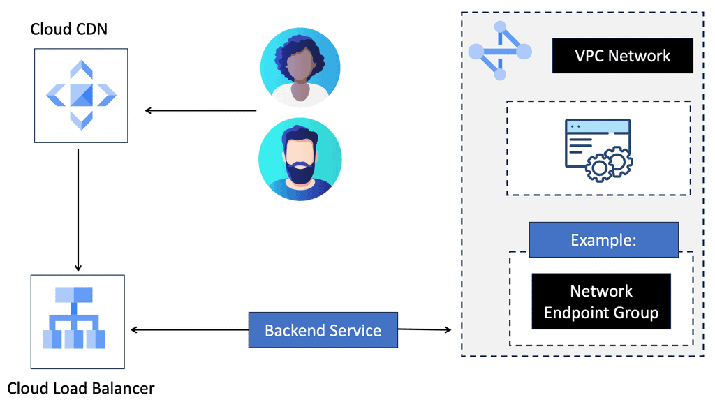
Integration with Google Cloud Platform: One of the remarkable advantages of Cloud CDN is its seamless integration with other Google Cloud Platform services. By leveraging Google Cloud Load Balancing, you can distribute traffic evenly across multiple backend instances while benefiting from Cloud CDN’s caching capabilities. This combination ensures optimal performance and high availability for your website.
Regional Internal HTTP(S) Load Balancers

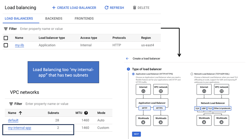
Regional Internal HTTP(S) Load Balancers provide a highly scalable and fault-tolerant solution for distributing traffic within a specific region in a Google Cloud environment. Designed to handle HTTP and HTTPS traffic, these load balancers intelligently distribute incoming requests among backend instances, ensuring optimal performance and availability.

Traffic Routing: Regional Internal HTTP(S) Load Balancers use advanced algorithms to distribute traffic across multiple backend instances evenly. This ensures that each instance receives a fair share of requests, preventing overloading and maximizing resource utilization.

Session Affinity: To maintain session consistency, these load balancers support session affinity, also known as sticky sessions. With session affinity enabled, subsequent requests from the same client are directed to the same backend instance, ensuring a seamless user experience.

Health Checking: Regional Internal HTTP(S) Load Balancers constantly monitor the health of backend instances to ensure optimal performance. If an instance becomes unhealthy, the load balancer automatically stops routing traffic to it, thereby maintaining the application’s overall stability and availability.

What is Cloud CDN?

Cloud CDN is a globally distributed CDN service offered by Google Cloud. It works by caching static and dynamic content from your website on Google’s edge servers, which are strategically located worldwide. When a user requests content, Cloud CDN delivers it from the nearest edge server, reducing latency and improving load times.

Scalability and Global Reach: Cloud CDN leverages Google’s extensive network infrastructure, ensuring scalability and global coverage. With a vast number of edge locations worldwide, your content can be quickly delivered to users, regardless of their geographical location.

Performance Optimization: By caching your website’s content at the edge, Cloud CDN reduces the load on your origin server, resulting in faster response times. It also helps minimize the impact of traffic spikes, ensuring consistent performance even during peak usage periods.

Cost Efficiency: Cloud CDN offers cost-effective pricing models, allowing you to optimize your content delivery expenses. You pay only for the data transfer and cache invalidation requests, making it an economical choice for websites of all sizes.

Cloud CDN seamlessly integrates with Google Cloud Load Balancing, providing an enhanced and robust content delivery solution. Load Balancing distributes incoming traffic across multiple backend instances, while Cloud CDN caches and delivers content to users efficiently.

Additional Performance Techniques

What are TCP Performance Parameters?

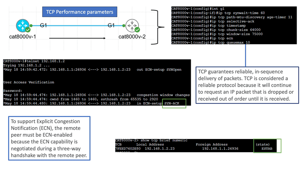
TCP (Transmission Control Protocol) is a fundamental communication protocol in computer networks. TCP performance parameters refer to various settings and configurations that govern the behavior and efficiency of TCP connections. These parameters can be adjusted to optimize network performance based on specific requirements and conditions.

1) – Window Size: The TCP window size determines the amount of data a receiver can accept before sending an acknowledgment. Adjusting the window size can impact throughput and response time, striking a balance between efficient data transfer and congestion control.

2) – Maximum Segment Size (MSS): The MSS defines the maximum amount of data transmitted in a single TCP segment. Optimizing the MSS can enhance network performance by reducing packet fragmentation and improving data transfer efficiency.

3) –  Congestion Window (CWND): CWND regulates the amount of data a sender can transmit without receiving acknowledgment from the receiver. Properly tuning the CWND can prevent network congestion and ensure smooth data flow.

4) –  Bandwidth-Delay Product (BDP): BDP represents the amount of data in transit between the sender and receiver at any given time. Calculating BDP helps determine optimal TCP performance settings, including window size and congestion control.

5) –  Delay-Based Parameter Adjustments: Specific TCP performance parameters, such as the retransmission timeout (RTO) and the initial congestion window (ICW), can be adjusted based on network delay characteristics. Fine-tuning these parameters can improve overall network responsiveness.

6) – Network Monitoring Tools: Network monitoring tools allow real-time monitoring and analysis of TCP performance parameters. These tools provide insights into network behavior, helping identify bottlenecks and areas for optimization.

7) –  Performance Testing: Conducting performance tests by simulating different network conditions can help assess the impact of TCP parameter adjustments. This enables network administrators to make informed decisions and optimize TCP settings for maximum efficiency.

Understanding TCP MSS

TCP MSS refers to the maximum amount of data encapsulated in a single TCP segment. It plays a vital role in determining data transmission efficiency across networks. By limiting the segment size, TCP MSS ensures that data packets fit within the underlying network’s Maximum Transmission Unit (MTU), preventing fragmentation and reducing latency.

Various factors influence the determination of TCP MSS. One crucial aspect is the MTU size of the network path between the source and the destination. Additionally, network devices, such as routers and firewalls, can affect the MSS, which might have MTU limitations. Considering these factors while configuring the TCP MSS for optimal performance is essential.

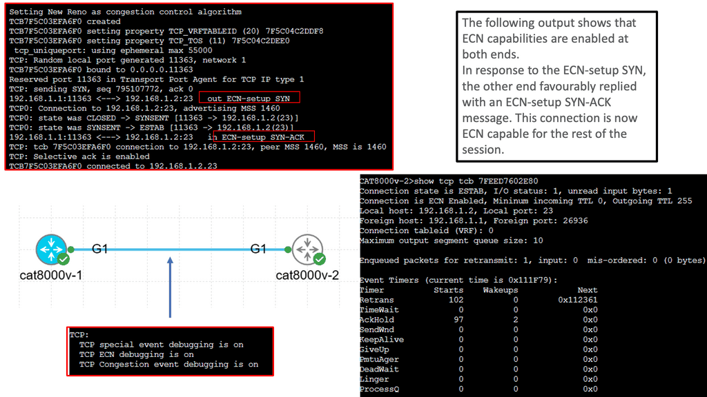
Configuring the TCP MSS requires adjusting the settings on both communication ends. The sender and receiver need to agree on a mutually acceptable MSS value. This can be achieved through negotiation during the TCP handshake process. Different operating systems and network devices may have different default MSS values. Understanding the specific requirements of your network environment is crucial for effective configuration.

Optimizing TCP MSS can yield several benefits for network performance. Ensuring that TCP segments fit within the MTU minimizes fragmentation, reducing the need for packet reassembly. This leads to lower latency and improved overall throughput. Optimizing TCP MSS can also enhance bandwidth utilization efficiency, allowing for faster data transmission across the network.

Load Balancer Types

Load balancers can be categorized into two main types: hardware load balancers and software load balancers. Hardware load balancers are dedicated devices designed to distribute traffic, while software load balancers are implemented as software applications or virtual machines. Each type has advantages and considerations, including cost, scalability, and flexibility.

A. Hardware Load Balancers:

Hardware load balancers are physical devices dedicated to distributing network traffic. They often come with advanced features like SSL offloading, session persistence, and health monitoring. While they offer exceptional performance and scalability, they can be costly and require specific expertise for maintenance.

B. Software Load Balancers:

Software load balancers are applications or modules that run on servers, effectively utilizing the server’s resources. They are flexible and easily configurable, making them a popular choice for small to medium-sized businesses. However, their scalability may be limited compared to hardware load balancers.

C. Virtual Load Balancers:

Virtual load balancers are software-based instances that run on virtual machines or cloud platforms. They offer the advantages of software load balancers while providing high scalability and easy deployment in virtualized environments. Virtual load balancers are a cost-effective solution for organizations leveraging cloud infrastructure.

In computing, you’ll do something similar. Your website receives many requests, which puts a lot of strain on it. There’s nothing unusual about having a website, but if no one visits it, there is no point in having one.

You run into problems when your server is overloaded with people turning on their appliances. At this point, things can go wrong; if too many people visit your site, your performance will suffer. Slowly, as the number of users increases, it will become unusable. That’s not what you wanted.

The solution to this problem lies in more resources. The choice between scaling up and scaling out depends on whether you want to replace your current server with a larger one or add another smaller one.

The scaling-up process

Scaling up is quite common when an application needs more power. The database may be too large to fit in memory, the disks are full, or more requests are causing the database to require more processing power.

Scaling up is generally easy because databases have historically had severe problems when run on multiple computers. If you try to make things work on various machines, they fail. What is the best method for sharing tables between machines? This problem has led to the development of several new databases, such as MongoDB and CouchDB.

However, it can be pretty expensive to scale up. A server’s price usually increases when you reach a particular specification. A new type of processor (that looks and performs like the previous one but costs much more than the old one) comes with this machine, a high-spec RAID controller, and enterprise-grade disks. Scaling up might be cheaper than scaling out if you upgrade components, but you’ll most likely get less bang for your buck this way. Nevertheless, if you need a couple of extra gigabytes of RAM or more disk space or if you want to boost the performance of a particular program, this might be the best option.

Scaling Out

Scaling out refers to having more than one machine. Scaling up has the disadvantage that you eventually reach an impossible limit. A machine can’t hold all the processing power and memory it needs. If you need more, what happens?

If you have a lot of visitors, people will say you’re in an envious position if a single machine can’t handle the load. As strange as it may sound, this is a good problem! Scaling out means you can add machines as you go. You’ll run out of space and power at some point, but scaling out will undoubtedly provide more computing power than scaling up.

Scaling out also means having more machines. Therefore, if one machine fails, other machines can still carry the load. Whenever you scale up, if one machine fails, it affects everything else.

There is one big problem with scaling out. You have three machines and a single cohesive website or web application. How can you make the three machines work together to give the impression of one machine? It’s all about load balancing!

Finally, load balancing

Now, let’s get back to load balancing. The biggest challenge in load balancing is making many resources appear as one. How can you make three servers look and feel like a single website to the customer?

How does the Web work?

This journey begins with an examination of how the Web functions. Under the covers of your browser, what happens when you click Go? The book goes into great detail, even briefly discussing the TCP (Transmission Control Protocol) layer.

While someone might be able to make an awe-inspiring web application, they may not be as familiar with the lower-level details that make it all function.

Fortunately, this isn’t an issue since kickass software doesn’t require knowledge of the Internet’s inner workings. It would be best to have a much better understanding of how it works to make your software quickly pass the competition.

**Challenge: Lack of Visibility**

Existing service provider challenges include a lack of network visibility into customer traffic. They are often unaware of the granular details of traffic profiles, leading them to over-provision bandwidth and link resilience. There are a vast amount of over-provisioned networks. Upgrades at a packet and optical layer occur without complete traffic visibility and justification. Many core networks are left at half capacity, just in a spike. Money is wasted on underutilization that could be spent on product and service innovation. You might need the analytical information for many reasons, not just bandwidth provisioning. 

**Required: Network Analytics** 

Popular network analytic capability tools are sFlow and NetFlow. Nodes capture and send sFlow information to a sFlow collector, where the operator can analyze it with the sFlow collector’s graphing and analytical tools. An additional tool that can be used is a centralized SDN controller, such as an SD-WAN Overlay, that can analyze the results and make necessary changes to the network programmatically. A centralized global viewpoint enabling load balancing can aid in intelligent multi-domain Traffic Engineering (TE) decisions.

Load Balancing with Service Mesh

### How Service Mesh Enhances Microservices

Microservices architecture breaks down applications into smaller, manageable services that can be independently deployed and scaled. However, this complexity introduces challenges in communication, monitoring, and security. A cloud service mesh addresses these issues by providing a dedicated layer for facilitating, managing, and orchestrating service-to-service communication.

### The Role of Load Balancing in a Service Mesh

One of the most significant features of a cloud service mesh is its ability to perform load balancing. Load balancing ensures that incoming traffic is distributed evenly across multiple servers, preventing any single server from becoming a bottleneck. This not only improves the performance and reliability of applications but also enhances user experience by reducing latency and downtime.

### Security and Observability

Security is paramount in any networked system, and a cloud service mesh significantly enhances it. By implementing mTLS (mutual Transport Layer Security), a service mesh encrypts communications between services, ensuring data integrity and confidentiality. Additionally, a service mesh offers observability features, such as tracing and logging, which provide insights into service behavior and performance, making it easier to identify and resolve issues.

### Real-World Applications

Many industry giants have adopted cloud service mesh technologies to streamline their operations. For instance, companies like Google and Netflix utilize service meshes to manage their vast array of microservices. This adoption underscores the importance of service meshes in maintaining seamless, efficient, and secure communication pathways in complex environments.

Before you proceed, you may find the following posts of interest:

  1. Transport SDN
  2. What Does SDN Mean
  3. Load Balancer Scaling
  4. Network Traffic Engineering
  5. Application Delivery Architecture

Load Balancing

One use case for load balancers to solve is availability. At some stage in time, machine failure happens. This is 100%. Therefore, you should avoid single points of failure whenever feasible. This signifies that machines should have replicas. In the case of front-end web servers, there should be at least two. When you have replicas of servers, a machine loss is not a total failure of your application. Therefore, your customer should notice as little during a machine failure event as possible.

Load Balancing and Traffic Engineering

We need network traffic engineering for load balancing that allows packets to be forwarded over non-shortest paths. Tools such as Resource Reservation Protocol (RSVP) and Fast Re-Route (FRR) enhance the behavior of TE. IGP-based TE uses a distributed routing protocol to discover the topology and run algorithms to find the shortest path. MPLS/RSVP-TE enhances standard TE and allows more granular forwarding control and the ability to differentiate traffic types for CoS/QoS purposes.

Constrained Shortest Path First

The shortest path algorithm, Constrained Shortest Path First (CSPF), provides label switch paths (LSP) to take any available path in the network. The MPLS control plane is distributed and requires a distributed IGP and label allocation protocol. The question is whether a centralized controller can solve existing traffic engineering problems. It will undoubtedly make orchestrating a network more manageable.

The contents of a TED have IGP scope domain visibility. Specific applications for TE purposes require domain-wide visibility to make optimal TE decisions. The IETF has defined the Path Computation Element (PCE) used to compute end-to-end TE paths.

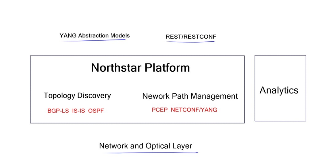
Link and TE attributes are shared with external components. Juniper’s SD-WAN product, NorthStar, adopts these technologies and promises network-wide visibility and enhanced TE capabilities. 

Use Case: Load Balancing with NorthStar SD-WAN controller

NorthStar is a new SD-WAN product by Juniper aimed at Service Providers and large enterprises that follow the service provider model. It is geared for the extensive network that owns Layer 2 links. NorthStar is an SD-WAN Path Computation Engine (PCE), defined in RFC 5440, that learns network state by Path Computation Element Protocol (PCEP).

It provides centralized control for path computation and TE purposes, enabling you to run your network more optimally. In addition, NorthStar gives you a programmable network with global visibility. It allowed you to spot problems and deploy granular control over traffic.

load balancing

They provide a simulation environment where they learn about all the traffic flows on the network. This allows you to simulate what “might” happen in specific scenarios. With a centralized view of the network, they can optimize flows throughout it, enabling a perfectly engineered and optimized network.

The controller can find the extra and unused capacity, allowing the optimization of underutilized spots in the network. The analytics provided is helpful for forecasting and capacity planning. It has an offline capability, providing offline versions of your network with all its traffic flows.

It takes inputs from:

  1. The network determines the topology and views link attributes.
  2. Human operators.
  3. Requests by Northbound REST API.

These inputs decide TE capabilities and where to place TE LSP in the network. In addition, it can modify LSP and create new ones, optimizing the network traffic engineering capabilities.

Understand network topology

Traditional networks commonly run IGP and build topology tables. This can get overly complicated when a multi-area or multi-IGP is running on the network. For network-wide visibility, NorthStar recommends BGP-LS. BGP-LS enables routers to export the contents of the TE database to BGP. It uses a new address family, allowing BGP to carry node and link attributes (metric, max amount of bandwidth, admin groups, and affinity bits) related to TE. BGP-LS can be used between different regions.

As its base is BGP, you can use scalable and high-availability features, such as route reflection, to design your BGP-LS network. While BGP is very scalable, its main advantage is reduced network complexity.

While NorthStar can peer with existing IGP (OSPF and ISIS), BGP-LS is preferred. Knowing the topology and attributes, the controller can set up LSP; for example, if you want a diverse LSP, it can perform a diverse LSP path computation. 

LSP & PCEP

There are three main types of LSPs in a NorthStar WAN-controlled network:

  1. A Vanilla-type LSP. It is a standard LSP, configured on the ingress router and signaled by RSVP.
  2. A delegated LSP is configured on the ingress router and then delegated to the controller, who is authorized to change this LSP.
  3. The controller initiates the third LSP via a human GUI or Northbound API operation.

PCEP (Path Computation Elements Protocol) communicates between all nodes and the controller. It is used to set up and modify LSP and enable dynamic and inter-area, inter-domain traffic, and engineered path setup. It consists of two entities, PCE and PCC. Path Computation Client (PCC) and Path Computation Element (PCE) get established over TCP.

Once the session is established, PCE builds the topology database (TED) using the underlying IGP or BGP-LS. BGP-LS has enhanced TLV capabilities that have been added for PCE to learn and develop this database. RSVP is still used to signal the LSP.

Closing Points on Load Balancing

Load balancing is a technique used to distribute network or application traffic across multiple servers. It ensures that no single server bears too much demand, which can lead to slowdowns or crashes. By spreading the load, it enhances the responsiveness and availability of websites and applications. At its core, load balancing helps in managing requests from users efficiently, ensuring each request is directed to the server best equipped to handle it at that moment.

There are several mechanisms and strategies employed in load balancing, each serving different needs and environments:

1. **Round Robin**: This is one of the simplest methods, where each server is assigned requests in a rotating order. It’s effective for servers with similar capabilities.

2. **Least Connections**: This method directs traffic to the server with the fewest active connections, ensuring a more even distribution of traffic during peak times.

3. **IP Hash**: This technique uses the client’s IP address to determine which server receives the request, providing a consistent experience for users.

Each method has its strengths and is chosen based on the specific requirements of the network environment.

The benefits of implementing load balancing are extensive:

– **Improved Scalability**: As demand increases, load balancing allows for the seamless addition of more servers to handle the load without downtime.

– **Enhanced Reliability**: By distributing traffic, load balancing minimizes the risk of server overload, thus reducing the chances of downtime.

– **Optimized Resource Use**: It ensures that all available server resources are utilized efficiently, reducing wastage and improving performance.

By leveraging these advantages, organizations can provide faster, more reliable digital services.

While load balancing offers numerous benefits, it is not without its challenges. Selecting the right load balancing strategy requires a deep understanding of the network environment and the specific needs of the application. Additionally, ensuring security during the load balancing process is crucial, as it involves the handling of sensitive data across multiple servers.


Summary: Load Balancing

Load balancing, the art of distributing workloads across multiple resources, is critical in optimizing performance and ensuring seamless user experiences. In this blog post, we explored the concept of load balancing, its significance in modern computing, and various strategies for effective load balancing implementation.

Understanding Load Balancing

Load balancing is a technique employed in distributed systems to evenly distribute incoming requests across multiple servers, networks, or resources. Its primary goal is to prevent any single resource from becoming overwhelmed, thus improving overall system performance, availability, and reliability.

Types of Load Balancing Algorithms

There are several load-balancing algorithms, each with its strengths and use cases. Let’s delve into some popular ones:

1. Round Robin: This algorithm distributes incoming requests equally among available resources in a circular manner, ensuring each resource receives a fair share of the workload.

2. Least Connections: In this algorithm, incoming requests are directed to the resource with the fewest active connections, effectively balancing the load based on current utilization.

3. Weighted Round Robin: This algorithm assigns servers different weights, allowing for a proportional distribution of workloads based on their capabilities.

Load Balancing Strategies and Approaches

When implementing load balancing, it’s crucial to consider the specific requirements and characteristics of the system. Here are a few common strategies:

1. Server-Side Load Balancing: This approach involves dedicated hardware or software acting as an intermediary between client requests and servers, distributing the load based on predefined rules or algorithms.

2. DNS Load Balancing: By manipulating DNS responses, this strategy distributes incoming requests across multiple IP addresses associated with different servers, achieving load balancing at the DNS level.

3. Content-Aware Load Balancing: This advanced technique analyzes the content of incoming requests and directs them to the most appropriate server based on factors like geographic location, user preferences, or server capabilities.

Load Balancing Best Practices

Implementing load balancing effectively requires following some best practices:

1. Monitoring and Scaling: Regularly monitor the performance of resources and scale them up or down based on demand to ensure optimal load distribution.

2. Redundancy and Failover: Implement redundancy mechanisms and failover strategies to ensure high availability in case of resource failures or disruptions.

3. Security Considerations: Implement proper security measures to protect against potential threats or vulnerabilities from load-balancing configurations.

Conclusion

Load balancing is a crucial aspect of modern computing, enabling efficient resource utilization, improved performance, and enhanced user experiences. By understanding the various load-balancing algorithms, strategies, and best practices, organizations can master the art of load-balancing and unlock the full potential of their distributed systems.

open vswitch

OVS Bridge and Open vSwitch (OVS) Basics


OVS bridge


Open vSwitch: What is OVS Bridge?

Open vSwitch (OVS) is an open-source multilayer virtual switch that provides a flexible and robust solution for network virtualization and software-defined networking (SDN) environments. It’s versatility and extensive feature set make it an invaluable tool for network administrators and developers. In this blog post, we will explore the world of Open vSwitch, its key features, benefits, and use cases.

Open vSwitch is a software switch designed for virtualized environments, enabling efficient network virtualization and SDN. It operates at layer 2 (data link layer) and layer 3 (network layer), offering advanced networking capabilities that enhance performance, security, and scalability.


Highlights: Open vSwitch

  • Barriers to Network Innovation

There are many barriers to network innovation, which makes it difficult for outsiders to drive features and innovate. Until recently, technologies were largely proprietary and controlled by a few vendors. The lack of tools available limited network virtualization and network resource abstraction. Many new initiatives are now challenging this space, and the Open vSwitch project with the OVS bridge, managed by the Open Network Foundation (ONF), is one of them. The ONF is a non-profit organization that promotes adopting software-defined networking through open standards and open networking.

  • The Role of OVS Switch

Since its release, the OVS switch has gained popularity and is now the de-facto open standard cloud networking switch. It changes the network landscape and moves the network edge to the hypervisor. The hypervisor is the new edge of the network. It resolves the problem of network separation; cloud users can now be assigned VMs with flexible configurations. It brings new challenges to networking and security, some of which the OVS network can alleviate in conjunction with OVS rules.


For pre-information, before you proceed, you may find the following post of interest:

  1. Container Networking
  2. OpenStack Neutron
  3. OpenStack Neuron Security Groups
  4. Neutron Networks
  5. Neutron Network


Open vSwitch.

Key OVS Bridge Discussion Points:


  • Introduction to OVS Bridge and how it can be used.

  • Discussion on virtual network bridges and flow rules.

  • Discussion on how the Open vSwitch works and the components involved.

  • Highlighting Flow Forwarding.

  • Programming the OVS switch with OVS rules.

  • A final note on OpenFlow and the OVS Bridge.


Back to Basics With Open vSwitch

The virtual switch

A virtual switch is a software-defined networking (SDN) device that enables the connection of multiple virtual machines within a single physical host. It is a Layer 2 device that operates within the virtualized environment and provides the same functionalities as a physical switch.

Virtual switches can be used to improve the performance and scalability of the network and are often used in cloud computing and virtualized environments. Virtual switches provide several advantages over their physical counterparts, including flexibility, scalability, and cost savings. In addition, as virtual switches are software-defined, they can be easily configured and managed by administrators.

Virtual switches are software-based switches that reside in the hypervisor kernel providing local network connectivity between virtual machines (and now containers). They deliver functions like MAC learning and features like link aggregation, SPAN, and sFlow, just like their physical switch companions have been doing for years. While these virtual switches are often found in more comprehensive SDN and network virtualization solutions, they are a switch that happens to be running in software.

Virtual Switch
Diagram: Virtual Switch. Source Fujitsu.


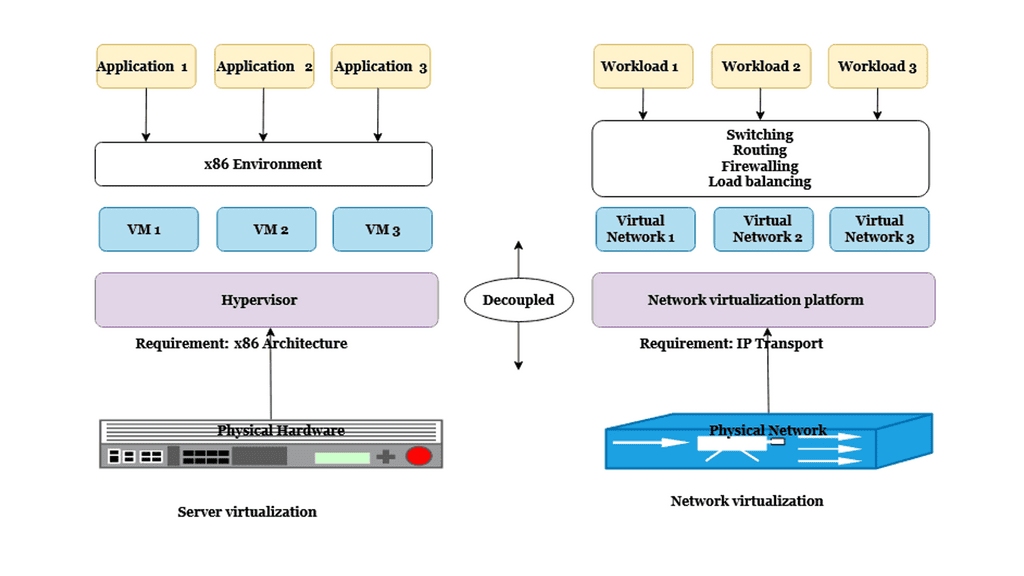
Network virtualization

network virtualization can also enable organizations to improve their network performance by allowing them to create multiple isolated networks. This can be particularly helpful when an organization’s network is experiencing congestion due to multiple applications, users, or customers. By segmenting the network into multiple isolated networks, each network can be optimized for the specific needs of its users.

In summary, network virtualization is a powerful tool that can enable organizations to control better and manage their network resources while still providing the flexibility and performance needed to meet the demands of their users. Network virtualization can help organizations improve their networks’ security, privacy, scalability, and performance by allowing organizations to create multiple isolated networks.

Network Virtualization
Diagram: Network and Server virtualization. Source Parallels.


Highlighting the OVS bridge

Open vSwitch is an open-source software switch designed for virtualized environments. It provides a multi-layer virtual switch designed to enable network connectivity and communication between virtual machines running within a single host or across multiple hosts. In addition, open vSwitch fully complies with the OpenFlow protocol, allowing it to be integrated with other OpenFlow-compatible software components.

The software switch can also manage various virtual networking functions, including LANs, routing, and port mirroring. Open vSwitch is highly configurable and can construct complex virtual networks. It supports a variety of features, including support for multiple VLANs, support for network isolation, and support for dynamic port configurations. As a result, open vSwitch is a critical component of many virtualized environments, providing an essential and powerful tool for managing the network environment.


  • A simple flow-based switch

Open vSwitch originates from the academic labs from a project known as Ethan – SIGCOMM 2007. Ethan created a simple flow-based switch with a central controller. The central controller has end-to-end visibility, allowing policies to be applied to one place while affecting many data plane devices. In addition, central controllers make orchestrating the network much more accessible. SIGCOMM 2007 introduced the OpenFlow protocol – SIGCOMM CCR 2008 and the first Open vSwitch (OVS) release in early 2009.


Key Features of Open vSwitch:

Virtual Switching: Open vSwitch allows the creation of virtual switches, enabling network administrators to define and manage multiple isolated networks on a single physical machine. This feature is particularly useful in cloud computing environments, where virtual machines (VMs) require network connectivity.

Flow Control: Open vSwitch supports flow-based packet processing, allowing administrators to define rules to handle network traffic efficiently. This feature enables fine-grained control over network traffic, implementing Quality of Service (QoS) policies, and enhancing network performance.

Network Virtualization: Open vSwitch enables network virtualization by supporting network overlays such as VXLAN, GRE, and Geneve. This allows the creation of virtual networks that span physical infrastructure, simplifying network management and enabling seamless migration of virtual machines across different hosts.

SDN Integration: Open vSwitch seamlessly integrates with SDN controllers, such as OpenDaylight and OpenFlow, enabling centralized network management and programmability. This integration empowers administrators to automate network provisioning, optimize traffic routing, and implement dynamic policies.

Benefits of Open vSwitch:

Flexibility: Open vSwitch offers a wide range of features and APIs, providing flexibility to adapt to various network requirements. Its modular architecture allows administrators to customize and extend functionalities per their needs, making it highly versatile.

Scalability: Open vSwitch scales effortlessly as network demands grow, efficiently handling large virtual machines and network flows. Its distributed nature enables load balancing and fault tolerance, ensuring high availability and performance.

Cost-Effectiveness: Being an open-source solution, Open vSwitch eliminates the need for expensive proprietary hardware. This reduces costs and enables organizations to leverage the benefits of software-defined networking without a significant investment.

Use Cases:

Cloud Computing: Open vSwitch plays a crucial role in cloud computing environments, enabling network virtualization, multi-tenant isolation, and seamless VM migration. It facilitates the creation and management of virtual networks, enhancing the agility and efficiency of cloud infrastructure.

SDN Deployments: Open vSwitch integrates seamlessly with SDN controllers, making it an ideal choice for SDN deployments. It allows for centralized network management, dynamic policy enforcement, and programmability, enabling organizations to achieve greater control and flexibility over their networks.

Network Testing and Development: Open vSwitch provides a powerful tool for testing and development. Its extensive feature set and programmability allow developers to simulate complex network topologies, test network applications, and evaluate network performance under different conditions.


Open vSwitch (OVS)

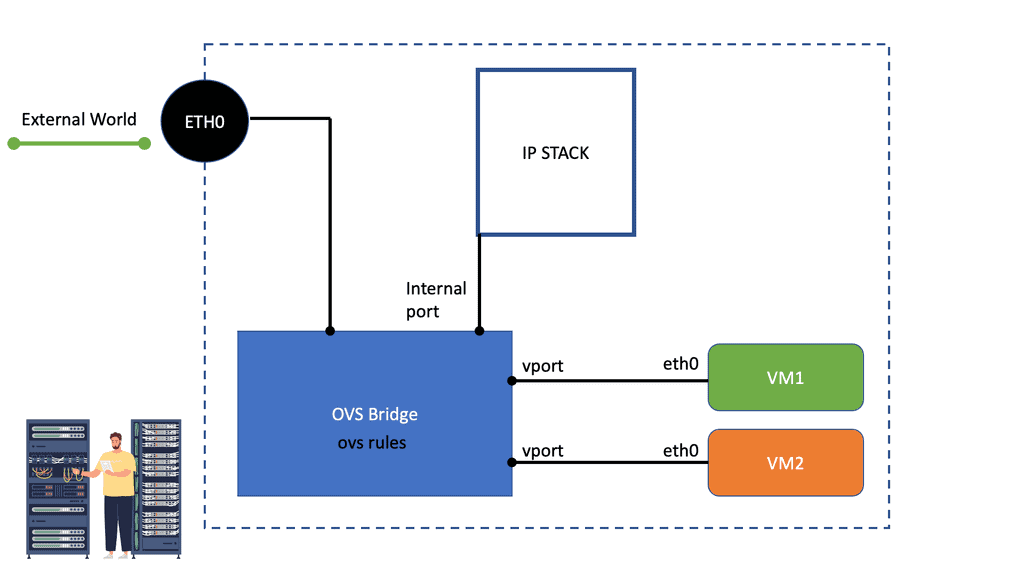
The OVS bridge is a multilayer virtual switch implemented in software. It uses virtual network bridges and flows rules to forward packets between hosts. It behaves like a physical switch, only virtualized. Namespaces and instance tap interfaces connect to what is known as OVS bridge ports.

Like a traditional switch, OVS maintains information about connected devices, such as MAC addresses. In addition, it enhances the monolithic Linux Bridge plugin and includes overlay networking (GRE & VXLAN), providing multi-tenancy in cloud environments. 

open vswitch
Diagram: The Open vSwitch basic layout.


Programming the Open vSwitch and OVS rules

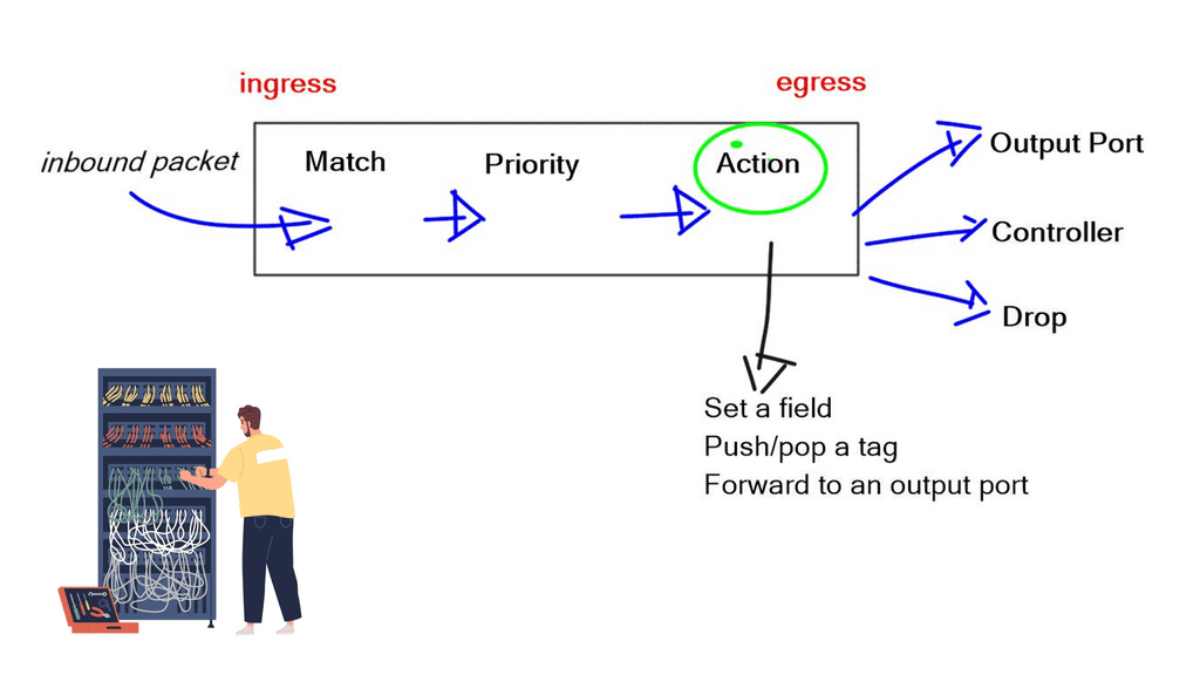
The OVS switch can also be integrated with hardware and serve as the control plane for switching silicon. Programming flow rules work differently in the OVS switch than in the standard Linux Bridge. The OVS plugin does not use VLANs to tag traffic. Instead, it programs OVS flow rules on the virtual switches that dictate how traffic should be manipulated before being forwarded to the exit interface. The OVS rules essentially determine how inbound and outbound traffic should be treated. 

OVS has two fail modes a) Standalone and b) Secure. Standalone is the default mode and acts as a learning switch. Secure mode relies on the controller element to insert flow rules. Therefore, the secure mode has a dependency on the controller.

OVS bridge
Diagram: OVS Bridge: Source OpenvSwitch.


Open vSwitch Flow Forwarding.

Kernel mode, known as “fast path” processing, is where it does the switching. If you relate this to hardware components on a physical device, the kernel mode will map to the ASIC. User mode is known as the “slow path.” If there is a new flow, the kernel doesn’t know about the user mode and is instructed to engage. Once the flow is active, the user mode should not be invoked. So you may take a hit the first time.

The first packet in a flow goes to the userspace ovs-vswitchd, and subsequent packets hit cached entries in the kernel. When the kernel module receives a packet, the cache is inspected to determine if there is a flow entry. The associated action is carried out on the packet if a corresponding flow entry is found in the cache.

This could be forwarding the packet or modifying its headers. If no cache entry is found, the packet is passed to the userspace ovs-vswitchd process for processing. Subsequent packets are processed in the kernel without userspace interaction. The processing speed of the OVS is now faster than the original Linux Bridge. It also has good support for mega flows and multithreading

OVS rules
Diagram: OVS rules and traffic flow.


OVS component architecture

There are several CLI tools to interface with the various components:

CLI Component

OVS Component

Ovs-vsctl manages the state 

in the ovsdb-server

Ovs-appctl sends commands

to the ovs-vswitchd

Ovs-dpctl is the

Kernal module configuration

ovs-ofctl work with the 

 OpenFlow protocols


what is OVS bridge
Diagram: What is OVS bridge? The components involved.


You may have an off-host component, such as the controller. It communicates and acts as a manager of a set of OVS components in a cluster. The controller has a global view and manages all the components. An example controller is OpenDaylight. OpenDaylight promotes the adoption of SDN and serves as a platform for Network Function Virtualization (NFV).

NFV virtualized network services instead of using physical function-specific hardware. A northbound interface exposes the network application and southbound interfaces interface with the OVS components. 

  • RYU provides a framework for SDN controllers and allows you to develop controllers. It is written in Python. It supports OpenFlow, Netconf, and OF-config.

There are many interfaces used to communicate across and between components. The database has a management protocol known as OVSDB, RFC 7047. OVS has a local database server on every physical host. It maintains the configuration of the virtual switches. Netlink communicates between user and kernel modes and between different userspace processes. It is used between ovs-vswitchd and openvswitch.ko and is designed to transfer miscellaneous networking information.


OpenFlow and the OVS bridge

OpenFlow can also be used to talk and program the OVS. The ovsdb-server interfaces with an external controller (if used) and the ovs-vswitchd interface. Its purpose is to store information for the switches. Its state is persistent.

The central CLI tool is ovs-vsctlThe ovs-vswitchd interface with an external controller, kernel via Netlink, and the ovsdb server. Its purpose is to manage multiple bridges and is involved in the data path. It’s a core system component for the OVS. Two CLI tools ovs-ofctl and ovs-appctl are used to interface with this.


Linux containers and networking

OVS can make use of Linux and Docker containers. Containers provide a layer of isolation that reduces communication in humans. They make it easy to build out example scenarios. Starting a container takes milliseconds compared to the minutes of a virtual machine.

Deploying container images is much faster if less data needs to travel across the fabric. Elastic applications with frequent state changes and dynamic resource allocation can be built more efficiently with containers. 

Linux and Docker containers represent a fundamental shift in how we consume and manage applications. Libvirt is a tool used to make use of containers. It’s a virtualization application for Linux. Linux containers involve process isolation in Linux, so instead of running an entire-blown VM, you can do a container, but you share the same kernel but are entirely isolated.

Each container has its view of networking and processes. Containers isolate instances without the overhead of a VM. A lightweight way of doing things on a host and builds on the mechanism in the kernel.


Source versus package install

There are two paths for installation, a) Source code and b) Package installation based on your Linux distribution. The source code install is primarily used if you are a developer and is helpful if you are trying to make an extension or focusing on hardware component integration; before accessing the Repo-install, any build dependencies, such as git, autoconf, and libtool.

Then you pull the image from GitHub with the “clone” command. <git clone https://github.com/openvswitch/ovs>. Running from source code is a lot more difficult than installing through distribution. All the dependencies will be done for you when you install from packages. 

Conclusion:

Open vSwitch is a feature-rich and highly flexible virtual switch that empowers network administrators and developers to build efficient and scalable networks. Its support for network virtualization, flow control, and SDN integration makes it a valuable tool in cloud computing environments, SDN deployments, and network testing and development. By leveraging Open vSwitch, organizations can unlock the full potential of network virtualization and software-defined networking, enhancing their network capabilities and driving innovation in the digital era.


open vswitch

nuage-logo-black-background-hr

SD WAN Tutorial: Nuage Networks


Nuage Networks

The following post details Nuage Netowrk and its response to SD-WAN. Part 2 can be found here with Nuage Network and SD-WAN. It’s a 24/7 connected world, and traffic diversity puts the Wide Area Network (WAN) edge to the test. Today’s applications should not be hindered by underlying network issues or a poorly designed WAN. Instead, the business requires designers to find a better way to manage the WAN by adding intelligence via an SD WAN Overlay with improved flow management, visibility, and control.

The WAN Monitoring role has changed from providing basic inter-site connectivity to adapting technology to meet business applications’ demands. It must proactively manage flows over all available paths, regardless of transport type. Business requirements should drive today’s networks, and the business should dictate the directions of flows, not the limitations of a routing protocol. The remainder of the post relates to Nuage Network and services as a good foundation for an SD WAN tutorial.


For additional information, you may find the following posts helpful:

  1. SD WAN Security
  2. WAN Virtualization
  3. Data Center Site Selection


Nuage SD WAN.

Key Nuage Networks Discussion Points:


  • Introduction to Nuage Network and Nuage SD WAN.

  • Discussion on challenges of the traditional WAN.

  • Discussion on routing protocols at the WAN edge.

  • Highlighting best path and failover only.

  • The role of a policy-based WAN.


The building blocks of the WAN have remained stagnant while the application environment has dynamically shifted; sure, speeds and feeds have increased, but the same architectural choices that were best practice 10 or 15 years ago are still being applied, hindering rapid growth in business evolution. So how will the traditional WAN edge keep up with new application requirements? 


Nuage SD WAN

Nuage Networks SD-WAN solution challenges this space and overcomes existing WAN limitations by bringing intelligence to routing at an application level. Now, policy decisions are made by a central platform that has full WAN and data center visibility. A transport-agnostic WAN optimizes the network and the decisions you make about it. In the eyes of Nuage, “every packet counts,” and mission-critical applications are always available on protected premium paths. 


 Routing Protocols at the WAN Edge 

Routing protocols assist in the forwarding decisions for traffic based on destinations, with decisions made hop-by-hop. This limits the number of paths the application traffic can take. Paths are further limited to routing loop restrictions – routing protocols will not take a path that could potentially result in a forwarding loop. Couple this with the traditional forwarding paradigms of primitive WAN designs, resulting in a network that cannot match today’s application requirements. We need to find more granular ways to forward traffic. 

There has always been a problem with complex routing for the WAN. BGP supports the best path, and ECMP provides some options for path selection. Solutions like Dynamic Multipoint VPN (DMVPN) operate with multiple control planes that are hard to design and operate. It’s painful to configure QOS policies per-link basis and design WAN solutions to incorporate multiple failure scenarios. The WAN is the most complex module of any network yet so important as it acts as the gateway to other networks such as the branch LAN and data center. 


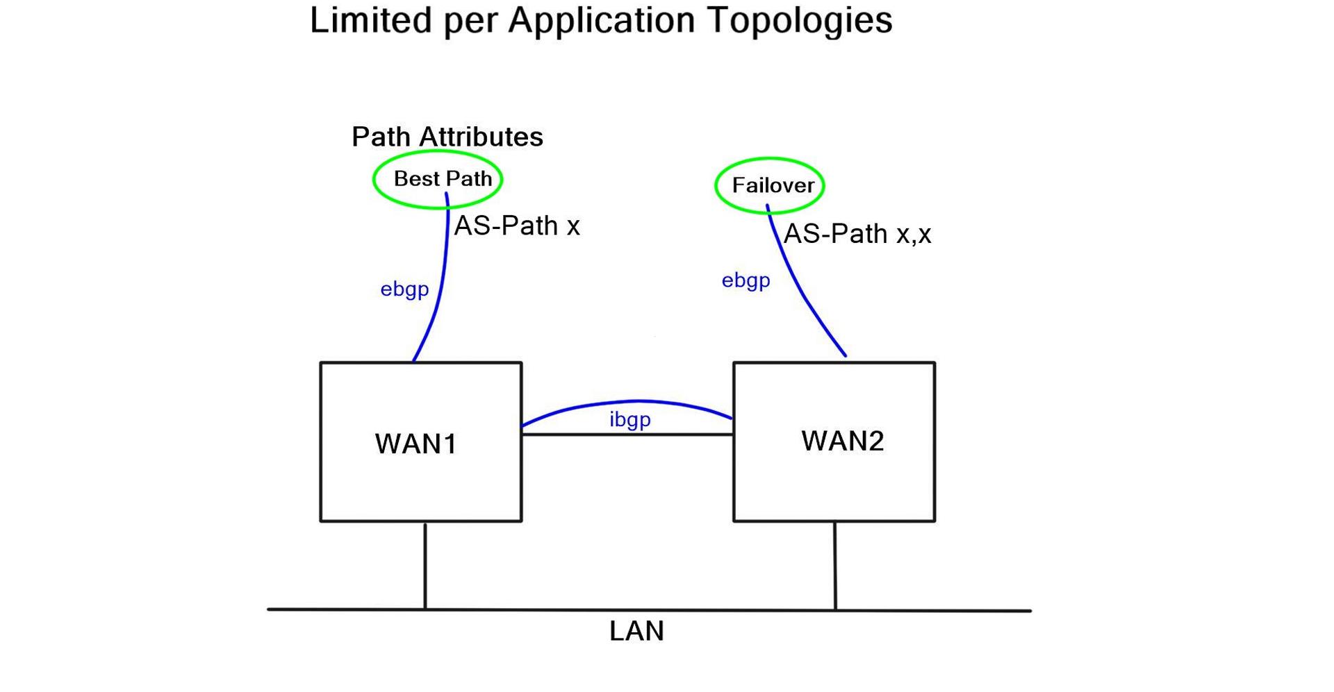
Best path & failover only.  

At the network edge, where there are two possible exit paths, choosing a path based on a unique business characteristic is often desirable. For example, use a historical jitter link for web traffic or premium links for mission-critical applications. The granularity for exit path selection should be flexible and selected based on business and application requirements. Criteria for exit points should be application-independent, allowing end-to-end network segmentation. 


nuage sd wan

External policy-based protocol

BGP is an external policy-based protocol commonly used to control path selection. BGP peers with other BGP routers to exchange Network Layer Reachability Information (NLRI). Its flexible policy-orientated approach and outbound traffic engineering offer tailored control for that network slice. As a result, it offers more control than an Interior Gateway Protocol (IGP) and reduces network complexity in large networks. These factors have made BGP the de facto WAN edge routing protocol. 

However, the path attributes that influence BGP does not consider any specifically tailored characteristics, such as unique metrics, transit performance, or transit brownouts. When BGP receives multiple paths to the same destination, it runs the best path algorithm to decide the best path to install in the IP routing table; generally, this path selection is based on AS-Path. Unfortunately, AS-Path is not an efficient measure of end-to-end transit. It misses the shape of the network, which can result in long path selection or paths experiencing packet loss. 


The traditional WAN

Traditional WAN routes down one path and, by default, have no awareness of what’s happening at the application level (packet loss, jitter, retransmissions). There have been many attempts to enhance the WANs behavior. For example, SLA steering based on enhanced object tracking would poll a metric such as Round Trip Time (RTT).

These methods are popular and widely implemented, but failover events occur on a configurable metric. All these extra configuration parameters make the WAN more complex. Simply acting as band-aids for a network that is under increasing pressure.

“Nuage Networks sponsor this post. All thoughts and opinions expressed are the authors.”


nuage networks

Airplane captain pressing switch on control panel for windshield heating with finger during flight

Data Center Failure

Data Center Failure

In today's data-driven world, the uninterrupted availability of data is crucial for businesses. Data center storage failover plays a vital role in ensuring continuous access to critical information. In this blog post, we will explore the importance of data center storage failover, its key components, implementation strategies, and best practices.

Data center storage failover is a mechanism that allows for seamless transition from a primary storage system to a secondary system in the event of a failure. This failover process ensures that data remains accessible and minimizes downtime in critical operations.

a) Redundant Storage Arrays: Implementing redundant storage arrays is essential for failover readiness. Multiple storage arrays, interconnected and synchronized, provide an extra layer of protection against hardware or software failures.

b) High-Speed Interconnects: Robust interconnectivity between primary and secondary storage systems is crucial for efficient data replication and failover.

c) Automated Failover Mechanisms: Employing automated failover mechanisms, such as failover controllers or software-defined storage solutions, enables swift and seamless transitions during a storage failure event.

a) Redundant Power Supplies: Ensuring redundant power supplies for storage systems prevents interruptions caused by power failures.

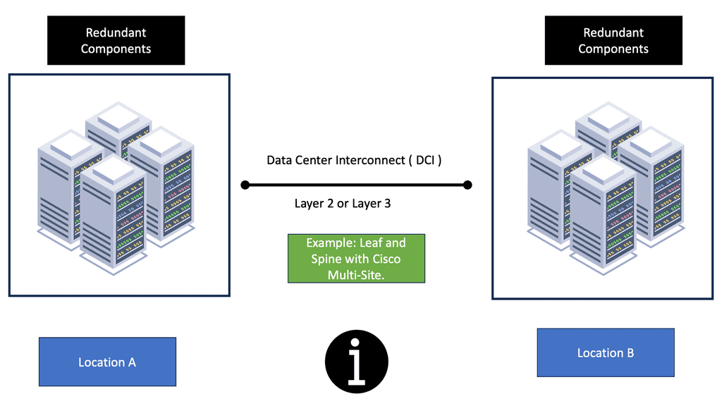
b) Geographically Diverse Data Centers: Distributing data across geographically diverse data centers provides added protection against natural disasters or localized service interruptions.

c) Regular Testing and Monitoring: Regularly testing failover mechanisms and monitoring storage systems' health is essential to identify and address any potential issues proactively.

a) Regular Backups: Implementing a robust backup strategy, including off-site backups, ensures data availability even in worst-case scenarios.

b) Scalability and Flexibility: Designing storage infrastructure with scalability and flexibility in mind allows for easy expansion or replacement of storage components without disrupting operations.

c) Documentation and Change Management: Maintaining up-to-date documentation and following proper change management protocols helps streamline failover processes and reduces the risk of errors during critical transitions.

Conclusion: Data center storage failover is a critical aspect of maintaining uninterrupted access to data in modern business environments. By understanding its importance, implementing the right components and strategies, and following best practices, organizations can ensure the availability and integrity of their valuable data, mitigating the risks associated with storage failures.

Highlights: Data Center Failure

**The Anatomy of a Data Center Failure**

Data center failures can occur due to a myriad of reasons, ranging from power outages and hardware malfunctions to software glitches and natural disasters. Each failure can have a ripple effect, impacting business continuity and data integrity. Recognizing the common causes of failures allows organizations to develop robust strategies to mitigate risks and ensure stability.

**Storage High Availability: The Shield Against Disruption**

At the core of mitigating data center failures is the concept of storage high availability (HA). This involves designing storage systems that are resilient to failures, ensuring data is always accessible, even when components fail. Techniques such as data replication, clustering, and failover mechanisms are employed to achieve high availability. By implementing these strategies, organizations can minimize downtime and protect their critical data assets.

**Implementing Proactive Measures**

Organizations must adopt a proactive approach to safeguard their data centers. Regular maintenance, monitoring, and testing of systems are essential to identify potential points of failure before they escalate. Investing in advanced technologies like predictive analytics and artificial intelligence can provide insights into system health and preemptively address issues. Additionally, having a well-documented disaster recovery plan ensures a swift response in the event of a failure.

Data Center Storage Protocols

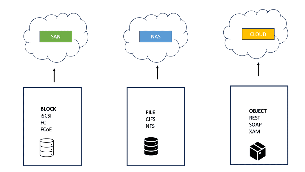
Protocols for communicating between storage and the outside world include iSCSI, SAS, SATA, and Fibre Channel (FC). It defines connections between HDDs, cables, backplanes, storage switches, or servers from one manufacturer connected to stuff from another manufacturer. Connectors must fit reliably, and there are a variety of them.

It seemed trivial at the time, but a specification lacking a definition of connector tolerances was a critical obstacle to SATA adoption (it seemed trivial at the time). This resulted in loose connectors, which resulted in a lot of bad press over a situation that could have been fixed with an errata note to fix the industry interoperability problem.

Transport Layer

Having established the physical, electrical, and digital connections, the transport layer creates, delivers, and confirms the delivery of the payloads, called frames information structures (FISs). The transport layer also handles addressing.

Storage protocols often connect multiple devices on a single wire; they include a global address so data sent down the wire gets to the right place. You can think of FIS packets as having a start and end of frames and a payload. Payloads can be either data or commands; here are the SATA FIS types (SAS and FC are similar but not identical):

Summary of storage protocols: they are simultaneously simple yet incredibly robust and complex. Error handling is the real merit of a storage protocol. When a connection is abruptly established or dropped, what happens? In the event of delays or non-acknowledgments, what happens? There is a lot of magic going on when it comes to handling errors. Each has different price tags and capabilities; choose the right tool based on your needs.

data center storage

**Recap on blog series**

This blog is the third in a series discussing the tail of active-active data centers and data center failure. The first blog focuses on GTM DNS-based load balancing and introduces failover challenges. The second discusses databases and Data Center Failover. This post addresses storage challenges, and finally, the fourth will focus on ingress and egress traffic flows.

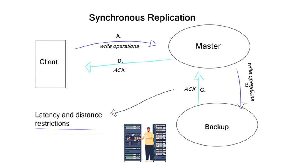
There are many factors to consider, such as the type of storage solution, synchronous or asynchronous replication, latency, and bandwidth restrictions between data centers. All of these are compounded by the complexity of microservices observability. And provide redundancy for these containerized environments.

Data Center Design

Nowadays, most SDN data center designs are based on the spine leaf architecture. However, even though the switching architecture may be the same for data center failure, every solution will have different requirements. For example, latency can drastically affect synchronous replications as a round trip time (RTT) is added to every write action. Still, this may not be as much of an issue for asynchronous replications. Design errors may also become apparent from specific failure scenarios, such as data center interconnect failure.

This potentially results in split-brain scenarios, so be careful when you try to over-automate and over-engineer things that should be kept simple in the first place. Split-brain occurs when both are active at the same time. Everything becomes out of sync, which may result in full tap storage restores.

Before you proceed, you may find the following helpful pre-information:

  1. Data Center Site Selection
  2. Redundant Links
  3. OpenStack Architecture
  4. Modular Building Blocks
  5. Kubernetes Networking 101
  6. Network Security Components
  7. Virtual Data Center Design
  8. Layer 3 Data Center

Data Center Failure

History of Storage

Small Computer System Interface (SCSI) was one of the first open storage standards. It was developed by the American National Standards Institute (ANSI) for attaching peripherals, such as storage, to computers. Initially, it wasn’t very flexible and could connect only 15 devices over a flat copper ribbon cable of 20 meters.

So, the fiber channel replaced the flat cable with a fiber cable. Now, we have a fiber infrastructure that overcomes the 20-meter restriction. However, it still uses the same SCSI protocol over fiber, commonly known as SCSI. Fibre Channel is used to transport SCSI information units over optical fiber.

Storage devices

We then started to put disks into enclosures, known as storage arrays. Storage arrays increase resilience and availability by eliminating single failure points (SPOFs). Applications would not write or own a physical disk but instead write to what is known as a LUN (Logical disk). A LUN is a unit that logically supports read/write operations. LUNs allow multi-access support by permitting numerous hosts to access the same storage array.

Eventually, vendors designed storage area networks (SAN). SAN networks provide access to block-level data storage. Block-level storage is used for SAN access, while file-level storage is used for network-attached storage (NAS) access. They no longer used SCSI and invented their routing protocol, FSPF routing.

Brocade invented FSPF, which is conceptually similar to OSPF for IP networks. They also implemented VSAN, similar to VLANs on Layer 2 networks, but used it for storage. VSAN is a collection of ports that represent a virtual fabric.

Remote disk access

Traditionally, servers would have a Host Bus Adapter (HBA) and run FC/ FCoE/iSCSI protocols to communicate with the remote storage array. Another method is sending individual file system calls to a remote file system, a NAS. The protocols used for this are CIFS and NFS. Microsoft developed CIFS, an open variation of the Server Message Block Protocol (SMB). NFS, developed by Sun Microsystems, runs over TCP and gives you access to shared files instead of SCSI, providing you access to remote disks.

The speed of file access depends on your application. Slow performances are generally not related to the protocols NFS or CIF. If your application is well-written and can read vast chunks of data, it will be refined over NFS. On the other hand, if your application is poorly written, it is best to use iSCSI. Then, the host will do most of the buffering.

Why not use LAN instead of a fiber channel? 

Initially, there was a wide variety of different operating systems. Most of these operating systems already used SCSI and the device drivers that implemented connectivity to load SCSI host adapters. The storage industry decided to offer the same SCSI protocol to the same device driver but over a fiber channel physical infrastructure.

Everything above the fiber channel was not changed. This allowed backward compatibility with old adapters, so they continued using the old SCSI protocols.

Fiber channels have their own set of requirements and terminology. The host still thinks they write to a disk 20m away, requiring tight timings. It must have low latency and a minimum distance of around 100 km. Nothing can be lost, so it must be lossless, and packets are critical.

FC requires lossless networks, which usually result in a costly dedicated network. With this approach, you have one network for LAN and one for storage.

Fiber channels over Ethernet eliminated fiber-only networks by offering I/O consultations between servers and switches. They took the entire fiber frame and put it into an Ethernet frame. FCoE requires lossless Ethernet (DCB) between the servers and the first switch, i.e., VN and VF ports. It is mainly used to reduce the amount of cabling between servers and switches. It is an access-tier solution. On the Ethernet side, we must have lossless Ethernet. There are several standards IEEE formed for this.

The first limited the sending device by issuing a PAUSE frame, known as 802.3x, which stops the server from sending data. As a result of the PAUSE frame, the server stops ALL transmissions. But we need a way to stop only the lossless part of the traffic, i.e., the FCoE traffic. This is 802.1qbb and allows you to stop a single class of services. There is also QCN (Congestion notification 802.1Qua), an end-to-end mechanism telling the sending device to slow down. All the servers, switches, and storage arrays negotiate the class parameters, deciding what will be lossless.

Data center failure: Storage replication for disaster recovery

The primary reasons for storage replication are disaster recovery and fulfilling service level agreements (SLA). How accurate will your data be when data center services fail from one DC to another? The level of data consistency depends on the solution in place and how you replicate your data. There are two types of storage replication: synchronous and asynchronous.

Synchronous has several steps.

The host writes to the disk, and the disk writes to the other disk in the remote location. Only when the other disk says, OK will an OK be returned to the host. Synchronous replication guarantees that the data is ideally in sync. However, it requires tight timeouts, severely limiting the distance between the two data centers. You need to implement asynchronous replication if there are long distances between data centers.

The host writes to the local disk, and the local disk immediately says OK without writing or receiving notifications from the remote disk. The local disk sends a written request to the remote disk in the background. If you use traditional LUN-based replication between two data centers, most solutions make one of these disks read-only and the other read-write.

Problems with latency occur when a VM is spawned in the data center with only the read-only copy, resulting in replication back to the writable copy. One major influential design factor is how much bandwidth storage replication consumes between data centers.

Data center failure: Distributed file systems

A better storage architecture is to use a system with distributed file systems—both ends are writable. Replication is not done at the disk level but at a file level. Your replication type is down to the recovery point objective (RPO), which is the terminology used for business continuity objectives. You must use synchronous replication if you require an RPO of zero. As discussed, it requires several steps before it is acknowledged to the application.

Synchronous also has distance and latency restrictions, which vary depending on the chosen storage solution. For example, VMware VSAN supports RTT of 5 ms. It is a distributed file system, so the replication is not done on a traditional LUN level but at a file level. It employs synchronous replication between data centers, adding RTT to every write. 

Most storage solutions eventually become consistent. You write to a file, the file locks, and the file is copied to the other end. This offers much better performance, but obviously, RPO is non-zero. 

Closing Points: Data Center Failure Storage

Downtime in a data center doesn’t just mean a temporary loss of access to information; it can lead to significant financial losses, damage to brand reputation, and a loss of customer trust. For industries such as finance, healthcare, and e-commerce, even a few minutes of downtime can result in catastrophic consequences. Thus, ensuring high availability is not just an IT concern but a business imperative.

One of the most effective ways to combat data center failures is through high availability (HA) storage solutions. These systems are designed to provide continuous access to data, even when parts of the system fail. High availability storage ensures that there are multiple pathways for data access, meaning if one path fails, another can take over seamlessly. This redundancy is critical for maintaining service during unexpected disruptions.

To implement a high availability storage solution, businesses must first assess their current infrastructure and identify potential weak points. This often involves deploying redundant hardware, such as servers and storage devices, and ensuring that they are strategically located to avoid a single point of failure. Additionally, leveraging cloud technologies can provide an extra layer of resilience, offering offsite backups and alternative processing capabilities.

Summary: Data Center Failure

In today’s digital era, data centers are pivotal in storing and managing vast information. However, even the most reliable systems can encounter failures. A robust data center storage failover mechanism is crucial for businesses to ensure uninterrupted operations and data accessibility. In this blog post, we explored the importance of data center storage failover and discussed various strategies to achieve seamless failover.

Understanding Data Center Storage Failover

Data center storage failover refers to automatically switching to an alternative storage system when a primary system fails. This failover mechanism guarantees continuous data availability, minimizes downtime, and safeguards against loss. By seamlessly transitioning to a backup storage system, businesses can maintain uninterrupted operations and prevent disruptions that could impact productivity and customer satisfaction.

Strategies for Implementing Data Center Storage Failover

Redundant Hardware Configuration: One primary strategy for achieving data center storage failover involves configuring redundant hardware components. These include redundant storage devices, power supplies, network connections, and controllers. By duplicating critical components, businesses can ensure that a failure in one component will not impede data accessibility or compromise system performance.

Replication and Synchronization: Implementing data replication and synchronization mechanisms is another effective strategy for failover. Businesses can create real-time copies of their critical data through continuous data replication between primary and secondary storage systems. This enables seamless failover, as the secondary system is already up-to-date and ready to take over in case of a failure.

Load Balancing: Load balancing is a technique that distributes data across multiple storage systems, ensuring optimal performance and minimizing the risk of overload. By evenly distributing data and workload, businesses can enhance system resilience and reduce the likelihood of storage failures. Load balancing also allows for efficient failover by automatically redirecting data traffic to healthy storage systems in case of failure.

Monitoring and Testing for Failover Readiness

Continuous monitoring and testing are essential to ensure the effectiveness of data center storage failover. Monitoring systems can detect early warning signs of potential failures, enabling proactive measures to mitigate risks. Regular failover testing helps identify gaps or issues in the failover mechanism, allowing businesses to refine their strategies and improve overall failover readiness.

Conclusion:

In the digital age, where data is the lifeblood of businesses, ensuring seamless data center storage failover is not an option; it’s a necessity. By understanding the concept of failover and implementing robust strategies like redundant hardware configuration, replication and synchronization, and load balancing, businesses can safeguard their data and maintain uninterrupted operations. Continuous monitoring and testing further enhance failover readiness, enabling businesses to respond swiftly and effectively in the face of unforeseen storage failures.

IT engineers team workers character and data center concept. Vector flat graphic design isolated illustration

Data Center Failover

Data Center Failover

In today's digital age, data centers play a vital role in storing and managing vast amounts of critical information. However, even the most advanced data centers are not immune to failures. This is where data center failover comes into play. This blog post will explore what data center failover is, why it is crucial, and how it ensures uninterrupted business operations.

Data center failover refers to seamlessly switching from a primary data center to a secondary one in case of a failure or outage. It is a critical component of disaster recovery and business continuity planning. Organizations can minimize downtime, maintain service availability, and prevent data loss by having a failover mechanism.

To achieve effective failover capabilities, redundancy measures are essential. This includes redundant power supplies, network connections, storage systems, and servers. By eliminating single points of failure, organizations can ensure that if one component fails, another can seamlessly take over.

Virtualization technologies, such as virtual machines and containers, play a vital role in data center failover. By encapsulating entire systems and applications, virtualization enables easy migration from one server or data center to another, ensuring minimal disruption during failover events.

Proactive monitoring and timely detection of potential issues are paramount in data center failover. Implementing comprehensive monitoring tools that track performance metrics, system health, and network connectivity allows IT teams to detect anomalies early on and take necessary actions to prevent failures.

Regular failover testing is crucial to validate the effectiveness of failover mechanisms and identify any potential gaps or bottlenecks. By simulating real-world scenarios, organizations can refine their failover strategies, improve recovery times, and ensure the readiness of their backup systems.

Highlights: Data Center Failover

### Understanding High Availability in Data Centers

In our increasingly digital world, data centers are the backbone of countless services and applications. High availability is a crucial aspect of data center operations, ensuring that these services remain accessible without interruption. But what exactly does high availability mean? In the context of data centers, it refers to the systems and protocols in place to guarantee that services are continuously operational, with minimal downtime. This is achieved through redundancy, failover mechanisms, and robust infrastructure design.

### Key Components of High Availability

To achieve high availability, data centers rely on several critical components. Firstly, redundancy is essential; this involves having duplicate systems and components ready to take over in case of a failure. Load balancing is another vital feature, distributing workloads across multiple servers to prevent any single point of failure. Additionally, disaster recovery plans are indispensable, providing a roadmap for restoring services in the event of a major disruption. By integrating these components, data centers can maintain service continuity and reliability.

### The Role of Monitoring and Maintenance

Continuous monitoring and proactive maintenance are pivotal in sustaining high availability in data centers. Monitoring tools track the performance and health of data center infrastructure, providing real-time alerts for any anomalies. Regular maintenance ensures that all systems are running optimally and helps prevent potential failures. This proactive approach not only minimizes downtime but also extends the lifespan of the data center’s equipment. By prioritizing monitoring and maintenance, data centers can swiftly address issues before they escalate.

### Challenges in Achieving High Availability

Despite the benefits, achieving high availability in data centers is not without its challenges. One significant hurdle is the cost associated with implementing redundant systems and sophisticated monitoring tools. Additionally, managing the complexity of diverse systems and ensuring seamless integration can be daunting. Data centers must also navigate evolving security threats and technological advancements to maintain their high availability standards. Addressing these challenges requires strategic planning and investment in cutting-edge technologies.

Database Redundancy

**Understanding High Availability: What It Means for Your Database**

High availability refers to a system’s ability to remain operational and accessible for the maximum possible time. In the context of data centers, this means your database should be able to withstand failures and still provide continuous service. Achieving this involves implementing redundancy, failover mechanisms, and load balancing to mitigate the risk of downtime and ensure that your data remains safeguarded.

**Key Strategies for Achieving High Availability**

1. **Redundancy and Load Balancing**: Implement redundant systems and components to eliminate single points of failure. Load balancing ensures that traffic is evenly distributed across servers, minimizing the risk of any one server becoming overwhelmed.

2. **Regular Backups and Disaster Recovery Planning**: Regular backups are a fundamental part of a high availability strategy. Pair this with a robust disaster recovery plan to ensure that, in the event of a failure, data can be restored quickly and operations can resume with minimal disruption.

3. **Cluster Configurations and Failover Systems**: Use cluster configurations to link multiple servers together, allowing them to act as a unified system. Failover systems automatically switch to a standby server if the primary one fails, thereby ensuring continuous availability.

**Challenges in Maintaining High Availability**

Despite best efforts, maintaining high availability comes with its challenges. These can include the cost of additional infrastructure, the complexity of managing redundant systems, and the potential for human error during maintenance tasks. It’s crucial to anticipate these challenges and prepare accordingly to ensure a seamless high availability strategy.

Creating Redundancy with Network Virtualization

In network virtualization, multiple physical networks are consolidated and operated as single or numerous independent networks by combining their resources. A virtual network is created to deploy and manage network services, while the hardware-based physical network only forwards packets. Network virtualization abstracts network resources traditionally delivered as hardware into software.

Overlay Network Protocols: Abstracting the data center

Modern virtualized data center fabrics must meet specific requirements to accelerate application deployment and support DevOps. To support multitenant support on shared physical infrastructure, fabrics must support scaling of forwarding tables, network segments, extended Layer 2 segments, virtual device mobility, forwarding path optimization, and virtualized networks. To achieve these requirements, overlay network protocols such as NVGRE, Cisco OTV, and VXLAN are used. Let’s define underlay and overlay to better understand various overlay protocols.

The underlay network is the physical infrastructure for an overlay network. It delivers packets as part of the underlying network across networks. Physical underlay networks provide unicast IP connectivity between any physical devices (servers, storage devices, routers, switches) in data center environments. However, technology limitations make underlay networks less scalable.

With network overlays, applications that demand specific network topologies can be deployed without modifying the underlying network. Overlays are virtual networks of interconnected nodes sharing a physical network. Multiple overlay networks can coexist simultaneously.

Redundant Data Centers

**Note: Blog Series**

This blog discusses the tail of active-active data centers and data center failover. The first blog focuses on the GTM Load Balancer and introduces failover challenges. The 3rd addresses Data Center Failure, focusing on the challenges and best practices for Storage. Much of this post addresses database challenges; the third is storage best practices; the final post will focus on ingress and egress traffic flows. 

Understanding VPC Peering

VPC Peering is a networking connection that allows different Virtual Private Clouds (VPCs) to communicate with each other using private IP addresses. It eliminates the need for complex VPN setups or public internet exposure, ensuring secure and efficient data transfer. Within Google Cloud, VPC Peering offers numerous advantages for organizations seeking to optimize their network architecture.


VPC Peering in Google Cloud brings a multitude of benefits. Firstly, it enables seamless communication between VPCs, regardless of their geographical location. This means that resources in different VPCs can communicate as if they were part of the same network, fostering collaboration and efficient data exchange. Additionally, VPC Peering helps reduce network costs by eliminating the need for additional VPN tunnels or dedicated interconnects.

Database Management Series

A Database Management System (DBMS) is a software application that interacts with users and other applications. It sits behind other elements known as “middleware” between the application and storage tier. It connects software components. Not all environments use databases; some store data in files, such as MS Excel. Also, data processing is not always done via query languages. For example, Hadoop has a framework to access data stored in files. Popular DBMS include MySQL, Oracle, PostgreSQL, Sybase, and IBM DB2. Database storage differs depending on the needs of a system.

Related: Before you proceed, you may find the following posts helpful:

  1. DNS Security Solutions
  2. DNS Security Designs
  3. ASA Failover
  4. DNS Reflection Attack
  5. Network Security Components
  6. Dropped Packet Test

Data Center Failover

Why is Data Center Failover Crucial?

1. Minimizing Downtime: Downtime can have severe consequences for businesses, leading to revenue loss, decreased productivity, and damaged customer trust. Failover mechanisms enable organizations to reduce downtime by quickly redirecting traffic and operations to a secondary data center.

2. Ensuring High Availability: Providing uninterrupted services is crucial for businesses, especially those operating in sectors where downtime can have severe implications, such as finance, healthcare, and e-commerce. Failover mechanisms ensure high availability by swiftly transferring operations to a secondary data center, minimizing service disruptions.

3. Preventing Data Loss: Data loss can be catastrophic for businesses, leading to financial and reputational damage. By implementing failover systems, organizations can replicate and synchronize data across multiple data centers, ensuring that in the event of a failure, data remains intact and accessible.

How Does Data Center Failover Work?

Datacenter failover involves several components and processes that work together to ensure smooth transitions during an outage:

1. Redundant Infrastructure: Failover mechanisms rely on redundant hardware, power systems, networking equipment, and storage devices. Redundancy ensures that if one component fails, another can seamlessly take over to maintain operations.

2. Automatic Detection: Monitoring systems constantly monitor the health and performance of the primary data center. In the event of a failure, these systems automatically detect the issue and trigger the failover process.

3. Traffic Redirection: Failover mechanisms redirect traffic from the primary data center to the secondary one. This redirection can be achieved through DNS changes, load balancers, or routing protocols. The goal is to ensure that users and applications experience minimal disruption during the transition.

4. Data Replication and Synchronization: Data replication and synchronization are crucial in data center failover. By replicating data across multiple data centers in real-time, organizations can ensure that data is readily available in case of a failover. Synchronization ensures that data remains consistent across all data centers.

What does a DBMS provide for applications?

It provides a means to access massive amounts of persistent data. Databases handle terabytes of data every day, usually much larger than what can fit into the memory of a standard O/S system. The size of the data and the number of connections mean that the database’s performance directly affects application performance. Databases carry out thousands of complex queries per second over terabytes of data.

The data is often persistent, meaning the data on the database system outlives the period of application execution. The data does not go away and sits. After that, the program stops running. Many users or applications access data concurrently, and measures are in place so concurrent users do not overwrite data. These measures are known as concurrency controls. They ensure correct results for simultaneous operations. Concurrency controls do not mean exclusive access to the database. The control occurs on data items, allowing many users to access the database but accessing different data items.

Data Center Failover and Database Concepts

The Data Model refers to how the data is stored in the database. Several options exist, such as the relational data model, a set of records. Also available is stored in XML, a hierarchical structure of labeled values. Finally, another solution includes a graph model where nodes represent all data.

The Schema sets up the structure of the database. You have to structure the data before you build the application. The database designers establish the Schema for the database. All data is stored within the Schema.

The Schema doesn’t change much, but data changes quickly and constantly. The Data Definition Language (DDL) sets up the Schema. It’s a standard of commands that define different data structures. Once the Schema is set up and the data is loaded, you start the query process and modify the data. This is done with the Data Manipulation Language (DML). DML statements are used to retrieve and work with data.

The SQL query language

The SQL query language is a standardized language based on relational algebra. It is a programming language used to manage data in a relational database and is supported by all major database systems. The SQL query engages with the database Query optimizer, which takes SQL queries and determines the optimum way to execute them on the database.

The language has two parts: the Data Definition Language (DDL) and the Data Manipulation Language (DML). DDL creates and drops tables, and DML (already mentioned) is used to query and modify the database with Select, Insert, Delete, and Update statements. The Select statement is the most commonly used and performs the database query.

Database Challenges

The database design and failover appetite is a business and non-technical decision. First, the company must decide on values acceptable to RTO (recovery time objective) and RPO (recovery point objective). How accurate do you want your data, and how long can a client application be in the read-only state? There are three main options a) Distributed databases with two-phase commit, b) Log shipping c) Read-only and read-write with synchronous replication.

With distributed databases and a two-phase commit, you have multiple synchronized copies of the database. It’s very complex, and latency can be a real problem affecting application performance. Many people don’t use this and go for log shipping instead. Log shipping maintains a separate copy of the database on the standby server.

There are two copies of a single database on different computers or the same computer with separate instances, primary and secondary databases. Only one copy is available at any given time. Any changes to the primary databases are logged or propagated to the other database copy.

Some environments have a 3rd instance, known as a monitor server. A monitor server records history, checks status, and tracks details of log shipping. A drawback to log shipping is that it has a non-zero RPO. It may be that a transaction was written just before the failure and, as a result, will be lost. Therefore, log shipping cannot guarantee zero data loss. An enhancement to log shipping is read-only and read-write copies of the database with synchronous replication between the two. With this method, there is no data loss, and it’s not as complicated as distributed databases with two-phase commit.

Data Center Failover Solution

If you have a transaction database and all the data is in one data center, you will have a problem with latency between the write database and the database client when you start the VM in the other DC. There is not much you can do about latency except shorten the link. Some believe WAN optimization will decrease latency, but many solutions will add it.

How well-written the application is will determine how badly the VM is affected. With very severely written applications, a few milliseconds can destroy performance. How quickly can you send SQL queries across the WAN link? How many queries per transaction does the application do? Poorly written applications require transactions encompassing many queries.

Multiple application stacks

A better approach would be to use multiple application stacks in different data centers. Load balancing can then be used to forward traffic to each instance. It is better to have various application stacks ( known as swim lanes ) that are entirely independent. Multiple instances on the same application allow you to take offline an instance without affecting others.

data center failover

A better approach is to have a single database server and ship the changes to the read-only database server. With the example of a two-application stack, one of the application stacks is read-only and eventually consistent, and the other is read-write. So if the client needs to make a change, for example, submit an order, how do you do this from the read-only data center? There are several ways to do this.

One way is with the client software. The application knows the transaction, uses a different hostname, and redirects requests to the read-write database. The hostname request can be used with a load balancer to redirect queries to the correct database. Another method is having applications with two database instances – read-only and read-write. So, every transaction will know if it’s read-only or read-write and will use the appropriate database instance. For example, purchasing would trigger the read-write instance, and browsing products would trigger read-only.

Most things we do are eventually consistent at a user’s face level. If you buy something online, even in the shopping cart, it’s not guaranteed until you select the buy button. Exceptions that are not fulfilled are made manually by sending the user an email.

Closing Points: Data Center Failover Databases

Database failover refers to the process of automatically switching to a standby database server when the primary server fails. This mechanism is designed to ensure that there is no interruption in service, allowing applications to continue to function without any noticeable downtime. In a data center, where multiple databases might be running simultaneously, having a robust failover strategy is essential for maintaining high availability.

A comprehensive failover system typically consists of several key components. Firstly, there is the primary database server, which handles the regular data processing and transactions. Secondly, one or more standby servers are in place, usually kept in sync with the primary server through regular updates. Monitoring tools are also critical, as they detect failures and trigger the failover process. Finally, a failover mechanism ensures a smooth transition, redirecting workload from the failed server to a standby server with minimal disruption.

Implementing an effective failover strategy involves several steps. Data centers must first assess their specific needs and determine the appropriate level of redundancy. Options range from simple active-passive setups, where a standby server takes over in case of failure, to more complex active-active configurations, which allow multiple servers to share the load and provide redundancy. Regular testing and validation of the failover process are essential to ensure reliability. Additionally, choosing the right database technology that supports failover, such as cloud-based solutions or traditional on-premise systems, is crucial.

While database failover offers numerous benefits, it also presents certain challenges. Ensuring data consistency and preventing data loss during failover is a primary concern. Network latency and bandwidth can impact the speed of failover, especially in geographically distributed data centers. Organizations must also consider the cost implications of maintaining redundant systems and infrastructure. Careful planning and ongoing monitoring are vital to address these challenges effectively.


Summary: Data Center Failover

In today’s technology-driven world, data centers play a crucial role in ensuring the smooth operation of businesses. However, even the most robust data centers are susceptible to failures and disruptions. That’s where data center failover comes into play – a critical strategy that allows businesses to maintain uninterrupted operations and protect their valuable data. In this blog post, we explored the concept of data center failover, its importance, and the critical considerations for implementing a failover plan.

Understanding Data Center Failover

Data center failover refers to the ability of a secondary data center to seamlessly take over operations in the event of a primary data center failure. It is a proactive approach that ensures minimal downtime and guarantees business continuity. Organizations can mitigate the risks associated with data center outages by replicating critical data and applications to a secondary site.

Key Components of a Failover Plan

A well-designed failover plan involves several crucial components. Firstly, organizations must identify the most critical systems and data that require failover protection. This includes mission-critical applications, customer databases, and transactional systems. Secondly, the failover plan should encompass robust data replication mechanisms to ensure real-time synchronization between the primary and secondary data centers. Additionally, organizations must establish clear failover triggers and define the roles and responsibilities of the IT team during failover events.

Implementing a Failover Strategy

Implementing a failover strategy requires careful planning and execution. Organizations must invest in reliable hardware infrastructure, including redundant servers, storage systems, and networking equipment. Furthermore, the failover process should be thoroughly tested to identify potential vulnerabilities or gaps in the plan. Regular drills and simulations can help organizations fine-tune their failover procedures and ensure a seamless transition during a real outage.

Monitoring and Maintenance

Once a failover strategy is in place, continuous monitoring and maintenance are essential to guarantee its effectiveness. Proactive monitoring tools should be employed to detect any issues that could impact the failover process. Regular maintenance activities, such as software updates and hardware inspections, should be conducted to keep the failover infrastructure in optimal condition.

Conclusion:

In today’s fast-paced business environment, where downtime can translate into significant financial losses and reputational damage, data center failover has become a lifeline for business continuity. By understanding the concept of failover, implementing a comprehensive failover plan, and continuously monitoring and maintaining the infrastructure, organizations can safeguard their operations and ensure uninterrupted access to critical resources.

dns load balancing failover

GTM Load Balancer

GTM Load Balancer

In today's fast-paced digital world, websites and applications face the constant challenge of handling high traffic loads while maintaining optimal performance. This is where Global Traffic Manager (GTM) load balancer comes into play. In this blog post, we will explore the key benefits and functionalities of GTM load balancer, and how it can significantly enhance the performance and reliability of your online presence.

GTM Load Balancer, or Global Traffic Manager, is a sophisticated, global server load balancing solution designed to distribute incoming network traffic across multiple servers or data centers. It operates at the DNS level, intelligently directing users to the most appropriate server based on factors such as geographic location, server health, and network conditions. By effectively distributing traffic, GTM load balancer ensures that no single server becomes overwhelmed, leading to improved response times, reduced latency, and enhanced user experience.

GTM load balancer offers a range of powerful features that enable efficient load balancing and traffic management. These include:

Geographic Load Balancing: By leveraging geolocation data, GTM load balancer directs users to the nearest or most optimal server based on their physical location, reducing latency and optimizing network performance.

Health Monitoring and Failover: GTM continuously monitors the health of servers and automatically redirects traffic away from servers experiencing issues or downtime. This ensures high availability and minimizes service disruptions.

Intelligent DNS Resolutions: GTM load balancer dynamically resolves DNS queries based on real-time performance and network conditions, ensuring that users are directed to the best available server at any given moment.

Scalability and Flexibility: One of the key advantages of GTM load balancer is its ability to scale and adapt to changing traffic patterns and business needs. Whether you are experiencing sudden spikes in traffic or expanding your global reach, GTM load balancer can seamlessly distribute the load across multiple servers or data centers. This scalability ensures that your website or application remains responsive and performs optimally, even during peak usage periods.

Integration with Existing Infrastructure: GTM load balancer is designed to integrate seamlessly with your existing infrastructure and networking environment. It can be easily deployed alongside other load balancing solutions, firewall systems, or content delivery networks (CDNs). This flexibility allows businesses to leverage their existing investments while harnessing the power and benefits of GTM load balancer.

GTM load balancer offers a robust and intelligent solution for achieving optimal performance and scalability in today's digital landscape. By effectively distributing traffic, monitoring server health, and adapting to changing conditions, GTM load balancer ensures that your website or application can handle high traffic loads without compromising on performance or user experience. Implementing GTM load balancer can be a game-changer for businesses seeking to enhance their online presence and stay ahead of the competition.

Highlights: GTM Load Balancer

### Types of Load Balancers

Load balancers come in various forms, each designed to suit different needs and environments. Primarily, they are categorized as hardware, software, and cloud-based load balancers. Hardware load balancers are physical devices, offering high performance but at a higher cost. Software load balancers are more flexible and cost-effective, running on standard servers. Lastly, cloud-based load balancers are gaining popularity due to their scalability and ease of integration with modern cloud environments.

### How Load Balancing Works

The process of load balancing involves several sophisticated algorithms. Some of the most common ones include Round Robin, where requests are distributed sequentially, and Least Connections, which directs traffic to the server with the fewest active connections. More advanced algorithms might take into account server response times and geographical locations to optimize performance further.

GTM load balancing is a technique used to distribute network or application traffic efficiently across multiple global servers. This ensures not only optimal performance but also increased reliability and availability for users around the globe. In this blog post, we’ll delve into the intricacies of GTM load balancing and explore how it can benefit your organization.

### How GTM Load Balancing Works

At its core, GTM load balancing involves directing user requests to the most appropriate server based on a variety of criteria, such as geographical location, server load, and network conditions. This is achieved through DNS-based routing, where the GTM system evaluates the best server to handle a request. By intelligently directing traffic, GTM load balancing minimizes latency, reduces server load, and enhances the user experience. Moreover, it provides a robust mechanism for disaster recovery by rerouting traffic to alternative servers in case of a failure.

Understanding GTM Load Balancer

A GTM load balancer is a powerful networking tool that intelligently distributes incoming traffic across multiple servers. It acts as a central management point, ensuring that each request is efficiently routed to the most appropriate server. Whether for a website, application, or any online service, a GTM load balancer is crucial in optimizing performance and ensuring high availability.

-Enhanced Scalability: A GTM load balancer allows businesses to scale their infrastructure seamlessly by evenly distributing traffic. As the demand increases, additional servers can be added without impacting the end-user experience. This scalability helps businesses handle sudden traffic spikes and effectively manage growth.

-Improved Performance: With a GTM load balancer in place, the workload is distributed evenly, preventing any single server from overloading. This results in improved response times, reduced latency, and enhanced user experience. By intelligently routing traffic based on factors like server health, location, and network conditions, a GTM load balancer ensures that each user request is directed to the best-performing server.

High Availability and Failover

-Redundancy and Failover Protection: A key feature of a GTM load balancer is its ability to ensure high availability. By constantly monitoring the health of servers, it can detect failures and automatically redirect traffic to healthy servers. This failover mechanism minimizes service disruptions and ensures business continuity.

-Global Server Load Balancing (GSLB): A GTM load balancer offers GSLB capabilities for businesses with a distributed infrastructure across multiple data centers. It can intelligently route traffic to the most suitable data center based on server response time, network congestion, and user proximity.

Flexibility and Traffic Management

– Geographic Load Balancing: A GTM load balancer can route traffic based on the user’s geographic location. By directing requests to the nearest server, businesses can minimize latency and deliver a seamless experience to users across different regions.

– Load Balancing Algorithms: GTM load balancers offer various load-balancing algorithms to cater to different needs. Businesses can choose the algorithm that suits their requirements, from simple round-robin to more advanced algorithms like weighted round-robin, least connections, and IP hash.

Example: Load Balancing with HAProxy

Understanding HAProxy

HAProxy, an open-source software, acts as a load balancer and proxy server. Its primary function is to distribute incoming web traffic across multiple servers, ensuring optimal utilization of resources. With its robust set of features and flexibility, HAProxy has become a go-to solution for high-performance web architectures.

HAProxy offers a plethora of features that empower businesses to achieve high availability and scalability. Some notable features include:

1. Load Balancing: HAProxy intelligently distributes incoming traffic across backend servers, preventing overloading and ensuring even resource utilization.

2. SSL/TLS Offloading: By offloading SSL/TLS encryption to HAProxy, backend servers are relieved from the computational overhead, resulting in improved performance.

3. Health Checking: HAProxy continuously monitors the health of backend servers, automatically routing traffic away from unresponsive or faulty servers.

4. Session Persistence: It provides session stickiness, allowing users to maintain their session state even when requests are served by different servers.

Key Features of GTM Load Balancer:

1. Geographic Load Balancing: GTM Load Balancer uses geolocation-based routing to direct users to the nearest server location. This reduces latency and ensures that users are connected to the server with the lowest network hops, resulting in faster response times.

2. Health Monitoring: The load balancer continuously monitors the health and availability of servers. If a server becomes unresponsive or experiences a high load, GTM Load Balancer automatically redirects traffic to healthy servers, minimizing service disruptions and maintaining high availability.

3. Flexible Load Balancing Algorithms: GTM Load Balancer offers a range of load balancing algorithms, including round-robin, weighted round-robin, and least connections. These algorithms enable businesses to customize the traffic distribution strategy based on their specific needs, ensuring optimal performance for different types of web applications.

Knowledge Check: TCP Performance Parameters

TCP (Transmission Control Protocol) is a fundamental protocol that enables reliable communication over the Internet. Understanding and fine-tuning TCP performance parameters are crucial to ensuring optimal performance and efficiency. In this blog post, we will explore the key parameters impacting TCP performance and how they can be optimized to enhance network communication.

TCP Window Size: The TCP window size represents the amount of data that can be sent before receiving an acknowledgment. It plays a pivotal role in determining the throughput of a TCP connection. Adjusting the window size based on network conditions, such as latency and bandwidth, can optimize TCP performance.

TCP Congestion Window: Congestion control algorithms regulate data transmission rate to avoid network congestion. The TCP congestion window determines the maximum number of unacknowledged packets in transit at any given time. Understanding different congestion control algorithms, such as Reno, New Reno, and Cubic, helps select the most suitable algorithm for specific network scenarios.

Duplicate ACKs and Fast Retransmit: TCP utilizes duplicate ACKs (Acknowledgments) to identify packet loss. Fast Retransmit triggers the retransmission of a lost packet upon receiving a certain number of duplicate ACKs. By adjusting the parameters related to Fast Retransmit and Recovery, TCP performance can be optimized for faster error recovery.

Nagle’s Algorithm: Nagle’s Algorithm aims to optimize TCP performance by reducing the number of small packets sent across the network. It achieves this by buffering small amounts of data before sending, thus reducing the overhead caused by frequent small packets. Additionally, adjusting the Delayed Acknowledgment timer can improve TCP efficiency by reducing the number of ACK packets sent.

The Role of Load Balancing

Load balancing involves spreading an application’s processing load over several different systems to improve overall performance in processing incoming requests. It splits the load that arrives into one server among several other devices, which can decrease the amount of processing done by the primary receiving server.

While splitting up different applications used to process a request among separate servers is usually the first step, there are several additional ways to increase your ability to split up and process loads—all for greater efficiency and performance. DNS load balancing failover, which we will discuss next, is the most straightforward way to load balance.

load balancing

DNS Load Balancing

DNS load balancing is the simplest form of load balancing. However, it is also one of the most powerful tools available. Directing incoming traffic to a set of servers quickly solves many performance problems. In spite of its ease and quickness, DNS load balancing cannot handle all situations.

A DNS server is a cluster of servers that answer queries together but cannot handle every DNS query on the planet. The solution lies in caching. Your system looks up servers from its storage by keeping a list of known servers in a cache. As a result, you can reduce the time it takes to walk a previously visited server’s DNS tree. Furthermore, it reduces the number of queries sent to the primary nodes.

nslookup command

The Role of a GTM Load Balancer

A GTM Load Balancer is a solution that efficiently distributes traffic across multiple web applications and services. In addition, it distributes traffic across various nodes, allowing for high availability and scalability. As a result, these load balancers enable organizations to improve website performance, reduce costs associated with hardware, and allow seamless scaling as application demand increases. It acts as a virtual traffic cop, ensuring incoming requests are routed to the most appropriate server or data center based on predefined rules and algorithms.

A Key Point: LTM Load Balancer

The LTM Load Balancer, short for Local Traffic Manager Load Balancer, is a software-based solution that distributes incoming requests across multiple servers. This ensures efficient resource utilization and prevents any single server from being overwhelmed. By intelligently distributing traffic, the LTM Load Balancer ensures high availability, scalability, and improved performance for applications and services.

GTM Load Balancing:

Continuously Monitors:

GTM Load Balancers continuously monitor server health, network conditions, and application performance. They use this information to distribute incoming traffic intelligently, ensuring that each server or data center operates optimally. By spreading the load across multiple servers, GTM Load Balancers prevent any single server from becoming overwhelmed, thus minimizing the risk of downtime or performance degradation.

Traffic Patterns:

GTM Load Balancers are designed to handle a variety of traffic patterns, such as round robin, least connections, and weighted least connections. It can also be configured to use dynamic server selection, allowing for high flexibility and scalability. GTM Load Balancers work with HTTP, HTTPS, TCP, and UDP protocols, which are well-suited to handle various applications and services.

GTM Load Balancers can be deployed in public, private, and hybrid cloud environments, making them a flexible and cost-effective solution for businesses of all sizes. They also have advanced features such as automatic failover, health checks, and SSL acceleration.

**Benefits of GTM Load Balancer**

1. Enhanced Website Performance: By efficiently distributing traffic, GTM Load Balancer helps balance the server load, preventing any single server from being overwhelmed. This leads to improved website performance, faster response times, and reduced latency, resulting in a seamless user experience.

2. Increased Scalability: As online businesses grow, the demand for server resources increases. GTM Load Balancer allows enterprises to scale their infrastructure by adding more servers or data centers. This ensures that the website can handle increasing traffic without compromising performance.

3. Improved Availability and Redundancy: GTM Load Balancer offers high availability by continuously monitoring server health and automatically redirecting traffic away from any server experiencing issues. It can detect server failures and quickly reroute traffic to healthy servers, minimizing downtime and ensuring uninterrupted service.

4. Geolocation-based Routing: Businesses often cater to a diverse audience across different regions in a globalized world. GTM Load Balancer can intelligently route traffic based on the user’s geolocation, directing them to the nearest server or data center. This reduces latency and improves the overall user experience.

5. Traffic Steering: GTM Load Balancer allows businesses to prioritize traffic based on specific criteria. For example, it can direct high-priority traffic to servers with more resources or specific geographic locations. This ensures that critical requests are processed efficiently, meeting the needs of different user segments.

Knowledge Check: Understanding TCP MSS

TCP MSS refers to the maximum amount of data encapsulated within a single TCP segment. It plays a crucial role in determining the efficiency and reliability of data transmission over TCP connections. By restricting the segment size, TCP MSS ensures that data can be transmitted without fragmentation, optimizing network performance.

Several factors come into play when determining the appropriate TCP MSS for a given network environment. One key factor is the underlying network layer’s Maximum Transmission Unit (MTU). The MTU defines the maximum size of packets that can be transmitted over the network. TCP MSS needs to be set lower than the MTU to avoid fragmentation. Network devices such as firewalls and routers may also impact the effective TCP MSS.

Configuring TCP MSS involves making adjustments at both ends of the TCP connection. It is typically done by setting the MSS value within the TCP headers. On the server side, the MSS value can be adjusted in the operating system’s TCP stack settings. Similarly, on the client side, applications or operating systems may provide ways to modify the MSS value. Careful consideration and testing are necessary to find the optimal TCP MSS for a network infrastructure.

The choice of TCP MSS can significantly impact network performance. Setting it too high may lead to increased packet fragmentation and retransmissions, causing delays and reducing overall throughput. Conversely, setting it too low may result in inefficient bandwidth utilization. Finding the right balance is crucial to ensuring smooth and efficient data transmission.

Related: Both of you proceed. You may find the following helpful information:

  1. DNS Security Solutions
  2. OpenShift SDN
  3. ASA Failover
  4. Load Balancing and Scalability
  5. Data Center Failover
  6. Application Delivery Architecture
  7. Port 179
  8. Full Proxy
  9. Load Balancing


GTM Load Balancer

GTM load balancer

A load balancer is a specialized device or software that distributes incoming network traffic across multiple servers or resources. Its primary objective is evenly distributing the workload, optimizing resource utilization, and minimizing response time. By intelligently routing traffic, load balancers prevent any single server from being overwhelmed, ensuring high availability and fault tolerance.

Load Balancer Functions and Features

Load balancers offer many functions and features that enhance network performance and scalability. Some essential functions include:

1. Traffic Distribution: Load balancers efficiently distribute incoming network traffic across multiple servers, ensuring no single server is overwhelmed.

2. Health Monitoring: Load balancers continuously monitor the health and availability of servers, automatically detecting and avoiding faulty or unresponsive ones.

3. Session Persistence: Load balancers can maintain session persistence, ensuring that requests from the same client are consistently routed to the same server, which is essential for specific applications.

4. SSL Offloading: Load balancers can offload the SSL/TLS encryption and decryption process, relieving the backend servers from this computationally intensive task.

5. Scalability: Load balancers allow for easy resource scaling by adding or removing servers dynamically, ensuring optimal performance as demand fluctuates.

Types of Load Balancers

Load balancers come in different types, each catering to specific network architectures and requirements. The most common types include:

1. Hardware Load Balancers: These devices are designed for load balancing. They offer high performance and scalability and often have advanced features.

2. Software Load Balancers: These are software-based load balancers that run on standard server hardware or virtual machines. They provide flexibility and cost-effectiveness while still delivering robust load-balancing capabilities.

3. Cloud Load Balancers: Cloud service providers offer load-balancing solutions as part of their infrastructure services. These load balancers are highly scalable, automatically adapting to changing traffic patterns, and can be easily integrated into cloud environments.

GTM and LTM Load Balancing Options

The Local Traffic Managers (LTM) and Enterprise Load Balancers (ELB) provide load-balancing services between two or more servers/applications in case of a local system failure. Global Traffic Managers (GTM) provide load-balancing services between two or more sites or geographic locations.

Local Traffic Managers, or Load Balancers, are devices or software applications that distribute incoming network traffic across multiple servers, applications, or network resources. They act as intermediaries between users and the servers or resources they are trying to access. By intelligently distributing traffic, LTMs help prevent server overload, minimize downtime, and improve system performance.

GTM and LTM Components

Before diving into the communication between GTM and LTM, let’s understand what each component does.

GTM, or Global Traffic Manager, is a robust DNS-based load-balancing solution that distributes incoming network traffic across multiple servers in different geographical regions. Its primary objective is to ensure high availability, scalability, and optimal performance by directing users to the most suitable server based on various factors such as geographic location, server health, and network conditions.

On the other hand, LTM, or Local Traffic Manager, is responsible for managing network traffic at the application layer. It works within a local data center or a specific geographic region, balancing the load across servers, optimizing performance, and ensuring secure connections.

As mentioned earlier, the most significant difference between the GTM and LTM is traffic doesn’t flow through the GTM to your servers.

  • GTM (Global Traffic Manager )

The GTM load balancer balances traffic between application servers across Data Centers. Using F5’s iQuery protocol for communication with other BIGIP F5 devices, GTM acts as an “Intelligent DNS” server, handling DNS resolutions based on intelligent monitors. The service determines where to resolve traffic requests among multiple data center infrastructures.

  • LTM (Local Traffic Manager)

LTM balances servers and caches, compresses, persists, etc. The LTM network acts as a full reverse proxy, handling client connections. The F5 LTM uses Virtual Services (VSs) and Virtual IPs (VIPs) to configure a load-balancing setup for a service.

LTMs offer two load balancing methods: nPath configuration and Secure Network Address Translation (SNAT). In addition to load balancing, LTM performs caching, compression, persistence, and other functions.

Communication between GTM and LTM:

BIG-IP Global Traffic Manager (GTM) uses the iQuery protocol to communicate with the local big3d agent and other BIG-IP big3d agents. GTM monitors BIG-IP systems’ availability, the network paths between them, and the local DNS servers attempting to connect to them.

The communication between GTM and LTM occurs in three key stages:

1. Configuration Synchronization:

GTM and LTM communicate to synchronize their configuration settings. This includes exchanging information about the availability of different LTM instances, their capacities, and other relevant parameters. By keeping the configuration settings current, GTM can efficiently make informed decisions on distributing traffic.

2. Health Checks and Monitoring:

GTM continuously monitors the health and availability of the LTM instances by regularly sending health check requests. These health checks ensure that only healthy LTM instances are included in the load-balancing decisions. If an LTM instance becomes unresponsive or experiences issues, GTM automatically removes it from the distribution pool, optimizing the traffic flow.

3. Dynamic Traffic Distribution:

GTM distributes incoming traffic to the most suitable LTM instances based on the configuration settings and real-time health monitoring. This ensures load balancing across multiple servers, prevents overloading, and improves the overall user experience. Additionally, GTM can reroute traffic to alternative LTM instances in case of failures or high traffic volumes, enhancing resilience and minimizing downtime.

  • A key point: TCP Port 4353

LTMs and GTMs can work together or separately. Most organizations that own both modules use them together, and that’s where the real power lies.
They use a proprietary protocol called iQuery to accomplish this.

Through TCP port 4353, iQuery reports VIP availability/performance to GTMs. A GTM can then dynamically resolve VIPs that reside on an LTM. With LTMs as servers in GTM configuration, there is no need to monitor VIPs directly with application monitors since the LTM is doing that, and iQuery reports it back to the GTM.

The Role of DNS With Load Balancing

The GTM load balancer offers intelligent Domain Name System (DNS) resolution capability to resolve queries from different sources to different data center locations. It loads and balances DNS queries to existing recursive DNS servers and caches the response or processes the resolution. This does two main things.

First, for security, it can enable DNS security designs and act as the authoritative DNS server or secondary authoritative DNS server web. It implements several security services with DNSSEC, allowing it to protect against DNS-based DDoS attacks.

DNS relies on UDP for transport, so you are also subject to UDP control plane attacks and performance issues. DNS load balancing failover can improve performance for load balancing traffic to your data centers. DNS is much more graceful than Anycast and is a lightweight protocol.

gtm load balancer
Diagram: GTM and LTM load balancer. Source: Network Interview

DNS load balancing provides several significant advantages.

Adding a duplicate system may be a simple way to increase your load when you need to process more traffic. If you route multiple low-bandwidth Internet addresses to one server, the server will have a more significant amount of total bandwidth.

DNS load balancing is easy to configure. Adding the additional addresses to your DNS database is as easy as 1-2-3! It doesn’t get any easier than this!

Simple to debug: You can work with DNS using tools such as dig, ping, and nslookup. In addition, BIND includes tools for validating your configuration, and all testing can be conducted via the local loopback adapter.

You will need a DNS server to have a domain name since you have a web-based system. At some point, you will undoubtedly need a DNS server. Your existing platform can be quickly extended with DNS-based load balancing!

**Issues with DNS Load Balancing**

In addition to its limitations, DNS load balancing also has some advantages.

Dynamic applications suffer from sticky behavior, but static sites rarely experience it. HTTP (and, therefore, the Web) is a stateless protocol. Chronic amnesia prevents it from remembering one request from another. To overcome this, a unique identifier accompanies each request. Identifiers are stored in cookies, but there are other sneaky ways to do this.

Through this unique identifier, your web browser can collect information about your current interaction with the website. Since this data isn’t shared between servers, if a new DNS request is made to determine the IP, there is no guarantee you will return to the server with all of the previously established information.

As mentioned previously, one in two requests may be high-intensity, and one in two may be easy. In the worst-case scenario, all high-intensity requests would go to only one server while all low-intensity requests would go to the other. This is not a very balanced situation, and you should avoid it at all costs lest you ruin the website for half of the visitors.

A fault-tolerant system. DNS load balancers cannot detect when one web server goes down, so they still send traffic to the space left by the downed server. As a result, half of all request

DNS Load Balancing Failover

DNS load balancing is the simplest form of load balancing. As for the actual load balancing, it is somewhat straightforward in how it works. It uses a direct method called round robin to distribute connections over the group of servers it knows for a specific domain. It does this sequentially. This means going first, second, third, etc.). To add DNS load balancing failover to your server, you must add multiple A records for a domain.

dns load balancing failover
Diagram: DNS load balancing. Source Imperva

GTM load balancer and LTM 

DNS load balancing failover

The GTM load balancer and the Local Traffic Manager (LTM) provide load-balancing services towards physically dispersed endpoints. Endpoints are in separate locations but logically grouped in the eyes of the GTM. For data center failover events, DNS is much more graceful than Anycast. With GTM DNS failover, end nodes are restarted (cold move) into secondary data centers with a different IP address.

As long as the DNS FQDN remains the same, new client connections are directed to the restarted hosts in the new data center. The failover is performed with a DNS change, making it a viable option for disaster recovery, disaster avoidance, and data center migration.

On the other hand, stretch clusters and active-active data centers pose a separate set of challenges. In this case, other mechanisms, such as FHRP localization and LISP, are combined with the GTM to influence ingress and egress traffic flows.

DNS Namespace Basics

Packets traverse the Internet using numeric IP addresses, not names, to identify communication devices. DNS was developed to map the IP address to a user-friendly name to make numeric IP addresses memorable and user-friendly. Employing memorable names instead of numerical IP addresses dates back to the early 1980s in ARPANET. Localhost files called HOSTS.txt mapped IP to names on all the ARPANET computers. The resolution was local, and any changes were implemented on all computers.

DNS basics
Diagram: DNS Basics. Source is Novell

Example: DNS Structure

This was sufficient for small networks, but with the rapid growth of networking, a hierarchical distributed model known as a DNS namespace was introduced. The database is distributed worldwide on what’s known as DNS nameservers that consist of a DNS structure. It resembles an inverted tree, with branches representing domains, zones, and subzones.

At the very top of the domain is the “root” domain, and then further down, we have Top-Level domains (TLD), such as .com or .net. and Second-Level domains (SLD), such as www.network-insight.net.

The IANA delegates management of the TLD to other organizations such as Verisign for.COM and. NET. Authoritative DNS nameservers exist for each zone. They hold information about the domain tree structure. Essentially, the name server stores the DNS records for that domain.

DNS Tree Structure

You interact with the DNS infrastructure with the process known as RESOLUTION. First, end stations request a DNS to their local DNS (LDNS). If the LDNS supports caching and has a cached response for the query, it will respond to the client’s requests.

DNS caching stores DNS queries for some time, which is specified in the DNS TTL. Caching improves DNS efficiency by reducing DNS traffic on the Internet. If the LDNS doesn’t have a cached response, it will trigger what is known as the recursive resolution process.

Next, the LDNS queries the authoritative DNS server in the “root” zones. These name servers will not have the mapping in their database but will refer the request to the appropriate TLD. The process continues, and the LDNS queries the authoritative DNS in the appropriate.COM .NET or. ORG zones. The method has many steps and is called “walking a tree.” However, it is based on a quick transport protocol (UDP) and takes only a few milliseconds.

DNS Load Balancing Failover Key Components

DNS TTL

Once the LDNS gets a positive result, it caches the response for some time, referenced by the DNS TTL. The DNS TTL setting is specified in the DNS response by the authoritative nameserver for that domain. Previously, an older and common TTL value for DNS was 86400 seconds (24 hours).

This meant that if there were a change of record on the DNS authoritative server, the DNS servers around the globe would not register that change for the TTL value of 86400 seconds.

This was later changed to 5 minutes for more accurate DNS results. Unfortunately, TTL in some end hosts’ browsers is 30 minutes, so if there is a failover data center event and traffic needs to move from DC1 to DC2, some ingress traffic will take time to switch to the other DC, causing long tails. 

DNS TTL
Diagram: DNS TTL. Source is Varonis

DNS pinning and DNS cache poisoning

Web browsers implement a security mechanism known as DNS pinning, where they refuse to take low TTL as there are many security concerns with low TTL settings, such as cache poisoning. Every time you read from the DNS namespace, there is potential DNS cache poisoning and a DNS reflection attack.

Because of this, all browser companies ignored low TTL and implemented their aging mechanism, which is about 10 minutes.

In addition, there are embedded applications that carry out a DNS lookup only once when you start the application, for example, a Facebook client on your phone. During data center failover events, this may cause a very long tail, and some sessions may time out.

DNS Packet Capture1

GTM Load Balancer and GTM Listeners

The first step is to configure GTM Listeners. A listener is a DNS object that processes DNS queries. It is configured with an IP address and listens to traffic destined to that address on port 53, the standard DNS port. It can respond to DNS queries with accelerated DNS resolution or GTM intelligent DNS resolution.

GTM intelligent Resolution is also known as Global Server Load Balancing (GSLB) and is just one of the ways you can get GTM to resolve DNS queries. It monitors a lot of conditions to determine the best response.

The GTM monitors LTM and other GTMs with a proprietary protocol called IQUERY. IQUERY is configured with the bigip_add utility. It’s a script that exchanges SSL certificates with remote BIG-IP systems. Both systems must be configured to allow port 22 on their respective self-IPs.

The GTM allows you to group virtual servers, one from each data center, into a pool. These pools are then grouped into a larger object known as a Wide IP, which maps the FQDN to a set of virtual servers. The Wide IP may contain Wild cards.

F5 GTM

Load Balancing Methods

When the GTM receives a DNS query that matches the Wide IP, it selects the virtual server and sends back the response. Several load balancing methods (Static and Dynamic) are used to select the pool; the default is round-robin. Static load balancing includes round-robin, ratio, global availability, static persists, drop packets, topology, fallback IP, and return to DNS.

Dynamic load balancing includes round trip time, completion time, hops, least connections, packet rate, QoS, and kilobytes per second. Both methods involve predefined configurations, but dynamic considers real-time events.

For example, topology load balancing allows you to select a DNS query response based on geolocation information. Queries are resolved based on the resource’s physical proximity, such as LDNS country, continent, or user-defined fields. It uses an IP geolocation database to help make the decisions. It helps service users with correct weather and news based on location. All this configuration is carried out with Topology Records (TR).

Anycast and GTM DNS for DC failover

Anycast means you advertise the same address from multiple locations. It is a viable option when data centers are geographically far apart. Anycast solves the DNS problem, but we also have a routing plane to consider. Getting people to another DC with Anycast can take time and effort.

It’s hard to get someone to go to data center A when the routing table says go to data center B. The best approach is to change the actual routing. As a failover mechanism, Anycast is not as graceful as DNS migration with F5 GTM.

Generally, if session disruption is a viable option, go for Anycast. Web applications would be OK with some session disruption. HTTP is stateless, and it will just resend. However, other types of applications might not be so tolerant. If session disruption is not an option and graceful shutdown is needed, you must use DNS-based load balancing. Remember that you will always have long tails due to DNS pinning in browsers, and eventually, some sessions will be disrupted.

Scale-Out Applications

The best approach is to do a fantastic scale-out application architecture. Begin with parallel application stacks in both data centers and implement global load balancing based on DNS. Start migrating users to the other data center, and when you move all the other users, you can shut down the instance in the first data center. It is much cleaner and safer to do COLD migrations. Live migrations and HOT moves (keep sessions intact) are challenging over Layer 2 links.

You need a different IP address. You don’t want to have stretched VLANs across data centers. It’s much easier to make a COLD move, change the IP, and then use DNS. The load balancer config can be synchronized to vCenter, so the load balancer definitions are updated based on vCenter VM groups.

Another reason for failures in data centers during scale-outs could be the lack of airtight sealing, otherwise known as hermetic sealing. Not having an efficient seal brings semiconductors in contact with water vapor and other harmful gases in the atmosphere. As a result, ignitors, sensors, circuits, transistors, microchips, and much more don’t get the protection they require to function correctly.

Data and Database Challenges

The main challenge with active-active data centers and failover events is with your actual DATA and Databases. If data center A fails, how accurate will your data be? You cannot afford to lose any data if you are running a transaction database.

Resilience is achieved by storage or database-level replication that employs log shipping or distribution between two data centers with a two-phase commit. Log shipping has an RPO of non-zero, as transactions could happen a minute before. A two-phase commit synchronizes multiple copies of the database but can slow down due to latency.

GTM Load Balancer is a robust solution for optimizing website performance and ensuring high availability. With its advanced features and intelligent traffic routing capabilities, businesses can enhance their online presence, improve user experience, and handle growing traffic demands. By leveraging the power of GTM Load Balancer, online companies can stay competitive in today’s fast-paced digital landscape.

Efficient communication between GTM and LTM is essential for businesses to optimize network traffic management. By collaborating seamlessly, GTM and LTM provide enhanced performance, scalability, and high availability, ensuring a seamless experience for end-users. Leveraging this powerful duo, businesses can deliver their services reliably and efficiently, meeting the demands of today’s digital landscape.

Closing Points on F5 GTM

Global Traffic Management (GTM) load balancing is a crucial component in ensuring your web applications remain accessible, efficient, and resilient on a global scale. With the rise of digital businesses, having a robust and dynamic load balancing strategy is more important than ever. In this blog, we will explore the intricacies of GTM load balancing, focusing on the capabilities provided by F5, a leader in application delivery networking.

F5’s Global Traffic Manager (GTM) is a powerful tool that optimizes the distribution of user requests by directing them to the most appropriate server based on factors such as location, server performance, and user requirements. The goal is to reduce latency, improve response times, and ensure high availability. F5 achieves this through intelligent DNS resolution and real-time network health monitoring.

1. **Intelligent DNS Resolution**: F5 GTM uses advanced algorithms to resolve DNS queries by considering factors such as server load, geographical location, and network latency. This ensures that users are directed to the server that can provide the fastest and most reliable service.

2. **Comprehensive Health Monitoring**: One of the standout features of F5 GTM is its ability to perform continuous health checks on servers and applications. This allows it to detect failures promptly and reroute traffic to healthy servers, minimizing downtime.

3. **Enhanced Security**: F5 GTM incorporates robust security measures, including DDoS protection and SSL/TLS encryption, to safeguard data and maintain the integrity of web applications.

4. **Scalability and Flexibility**: With F5 GTM, businesses can easily scale their operations to accommodate increased traffic and expand to new locations without compromising performance or reliability.

Integrating F5 GTM into your existing IT infrastructure requires careful planning and execution. Here are some steps to ensure a smooth implementation:

– **Assessment and Planning**: Begin by assessing your current infrastructure needs and identifying areas that require load balancing improvements. Plan your GTM strategy to align with your business goals.

– **Configuration and Testing**: Configure F5 GTM settings based on your requirements, such as setting up DNS zones, health monitors, and load balancing policies. Conduct thorough testing to ensure all components work seamlessly.

– **Deployment and Monitoring**: Deploy F5 GTM in your production environment and continuously monitor its performance. Use F5’s comprehensive analytics tools to gain insights and make data-driven decisions.

Summary: GTM Load Balancer

GTM Load Balancer is a sophisticated traffic management solution that distributes incoming user requests across multiple servers or data centers. Its primary purpose is to optimize resource utilization and enhance the user experience by intelligently directing traffic to the most suitable backend server based on predefined criteria.

Key Features and Functionality

GTM Load Balancer offers a wide range of features that make it a powerful tool for traffic management. Some of its notable functionalities include:

1. Health Monitoring: GTM Load Balancer continuously monitors the health and availability of backend servers, ensuring that only healthy servers receive traffic.

2. Load Distribution Algorithms: It employs various load distribution algorithms, such as Round Robin, Least Connections, and IP Hashing, to intelligently distribute traffic based on different factors like server capacity, response time, or geographical location.

3. Geographical Load Balancing: With geolocation-based load balancing, GTM can direct users to the nearest server based on location, reducing latency and improving performance.

4. Failover and Redundancy: In case of server failure, GTM Load Balancer automatically redirects traffic to other healthy servers, ensuring high availability and minimizing downtime.

Implementation Best Practices

Implementing a GTM Load Balancer requires careful planning and configuration. Here are some best practices to consider:

1. Define Traffic Distribution Criteria: Clearly define the criteria to distribute traffic, such as server capacity, geographical location, or any specific business requirements.

2. Set Up Health Monitors: Configure health monitors to regularly check the status and availability of backend servers. This helps in avoiding directing traffic to unhealthy or overloaded servers.

3. Fine-tune Load Balancing Algorithms: Based on your specific requirements, fine-tune the load balancing algorithms to achieve optimal traffic distribution and server utilization.

4. Regularly Monitor and Evaluate: Continuously monitor the performance and effectiveness of the GTM Load Balancer, making necessary adjustments as your traffic patterns and server infrastructure evolve.

Conclusion: In a world where online presence is critical for businesses, ensuring seamless traffic distribution and optimal performance is a top priority. GTM Load Balancer is a powerful solution that offers advanced functionalities, intelligent load distribution, and enhanced availability. By effectively implementing GTM Load Balancer and following best practices, businesses can achieve a robust and scalable infrastructure that delivers an exceptional user experience, ultimately driving success in today’s digital landscape.

rsz_load_balancing_

Full Proxy

Full Proxy

In the vast realm of computer networks, the concept of full proxy stands tall as a powerful tool that enhances security and optimizes performance. Understanding its intricacies and potential benefits can empower network administrators and users alike. In this blog post, we will delve into the world of full proxy, exploring its key features, advantages, and real-world applications.

Full proxy is a network architecture approach that involves intercepting and processing all network traffic between clients and servers. Unlike other methods that only handle specific protocols or applications, full proxy examines and analyzes every packet passing through, regardless of the protocol or application used. This comprehensive inspection allows for enhanced security measures and advanced traffic management capabilities.

Enhanced Security: By inspecting each packet, full proxy enables deep content inspection, allowing for the detection and prevention of various threats, such as malware, viruses, and intrusion attempts. It acts as a robust barrier safeguarding the network from potential vulnerabilities.

Advanced Traffic Management: Full proxy provides granular control over network traffic, allowing administrators to prioritize, shape, and optimize data flows. This capability enhances network performance by ensuring critical applications receive the necessary bandwidth while mitigating bottlenecks and congestion.

Application Layer Filtering: Full proxy possesses the ability to filter traffic at the application layer, enabling fine-grained control over the types of content that can pass through the network. This feature is particularly useful in environments where specific protocols or applications need to be regulated or restricted.

Enterprise Networks: Full proxy finds extensive use in large-scale enterprise networks, where security and performance are paramount. It enables organizations to establish robust defenses against cyber threats while optimizing the flow of data across their infrastructures.

Web Filtering and Content Control: Educational institutions and public networks often leverage full proxy solutions to implement web filtering and content control measures. By examining the content of web pages and applications, full proxy allows administrators to enforce policies and ensure compliance with acceptable usage guidelines.

Full proxy represents a powerful network architecture approach that offers enhanced security measures, advanced traffic management capabilities, and application layer filtering. Its real-world applications span across enterprise networks, educational institutions, and public environments. Embracing full proxy can empower organizations and individuals to establish resilient network infrastructures while fostering a safer and more efficient digital environment.

Highlights: Full Proxy

Understanding Full Proxy

Full Proxy refers to a web architecture that utilizes a proxy server to handle and process all client requests. Unlike traditional architectures where the client directly communicates with the server, Full Proxy acts as an intermediary, intercepting and forwarding requests on behalf of the client. This approach provides several advantages, including enhanced security, improved performance, and better control over web traffic.

At its core, a full proxy server acts as an intermediary between a user’s device and the internet. Unlike a simple proxy, which merely forwards requests, a full proxy server fully terminates and re-establishes connections on behalf of both the client and the server. This complete control over the communication process allows for enhanced security, better performance, and more robust content filtering.

Full Proxy Key Points:

a: – Enhanced Security: One of the primary reasons for the growing popularity of Full Proxy is its ability to bolster security measures. By acting as a gatekeeper between the client and the server, Full Proxy can inspect and filter incoming requests, effectively mitigating potential threats such as DDoS attacks, SQL injections, and cross-site scripting. Furthermore, Full Proxy can enforce strict authentication and authorization protocols, ensuring that only legitimate traffic reaches the server.

b: – Performance: Another significant advantage of Full Proxy is its impact on performance. With Full Proxy architecture, the proxy server can cache frequently requested resources, reducing the load on the server and significantly improving response times. Additionally, Full Proxy can employ compression techniques, minimizing the amount of data transmitted between the client and server, resulting in faster page loads and a smoother user experience.

c: – Control and Load Balancing: Full Proxy also offers granular control over web traffic. By intelligently routing requests, it allows for load balancing across multiple servers, ensuring optimal resource utilization and preventing bottlenecks. Additionally, Full Proxy can prioritize certain types of traffic, allocate bandwidth, and implement traffic shaping mechanisms, enabling administrators to manage network resources effectively.

d: – Comprehensive Content Filtering: Full proxies can enforce strict content filtering policies, making them ideal for organizations that need to regulate internet usage and block access to inappropriate or harmful content.

**Full Proxy Mode**

A full proxy mode is a proxy server that acts as an intermediary between a user and a destination server. The proxy server acts as a gateway between the user and the destination server, handling all requests and responses on behalf of the user. A full proxy mode aims to provide users with added security, privacy, and performance by relaying traffic between two or more locations.

In full proxy mode, the proxy server takes on the client role, initiating requests and receiving responses from the destination server. All requests are made on behalf of the user, and the proxy server handles the entire process and provides the user with the response. This provides the user with an added layer of security, as the proxy server can authenticate the user before allowing them access to the destination server.

**Increase in Privacy**

The full proxy mode also increases privacy, as the proxy server is the only point of contact between the user and the destination server. All requests sent from the user are relayed through the proxy server, ensuring that the user’s identity remains hidden. Additionally, the full proxy mode can improve performance by caching commonly requested content, reducing lag times, and improving the user experience.

Example Caching Proxy: What is Squid Proxy?

Squid Proxy is a widely-used caching proxy server that acts as an intermediary between clients and servers. It acts as a buffer, storing frequently accessed web pages and files locally, thereby reducing bandwidth usage and improving response times. Whether you’re an individual user or an organization, Squid Proxy can be a game-changer in optimizing your internet connectivity.

Features and Benefits of Squid Proxy

Squid Proxy offers a plethora of features that make it a valuable tool in the world of networking. From caching web content to controlling access and providing security, it offers a comprehensive package. Some key benefits of using Squid Proxy include:

1. Bandwidth Optimization: By caching frequently accessed web pages, Squid Proxy reduces the need to fetch content from the source server, resulting in significant bandwidth savings.

2. Faster Browsing Experience: With cached content readily available, users experience faster page load times and smoother browsing sessions.

3. Access Control: Squid Proxy allows administrators to implement granular access control policies, restricting or allowing access to specific websites or content based on customizable rules.

4. Security: Squid Proxy acts as a shield between clients and servers, providing an additional layer of security by filtering out malicious content, blocking potentially harmful websites, and protecting against various web-based attacks.

The Benefits of Full Proxy

– Enhanced Security: By acting as a middleman, Full Proxy provides an additional layer of security by inspecting and filtering incoming and outgoing traffic. This helps protect users from malicious attacks and unauthorized access to sensitive information.

– Performance Optimization: Full Proxy optimizes web performance through techniques such as caching and compression. Storing frequently accessed content and reducing the transmitted data size significantly improves response times and reduces bandwidth consumption.

– Content Filtering and Control: With Full Proxy, administrators can enforce content filtering policies, restricting access to certain websites or types of content. This feature is handy in educational institutions, corporate environments, or any setting where internet usage needs to be regulated.

Example of SSL Policies with Google Cloud

**The Importance of SSL Policies**

Implementing robust SSL policies is crucial for several reasons. Firstly, they help in maintaining data integrity by preventing data from being tampered with during transmission. Secondly, SSL policies ensure data confidentiality by encrypting information, making it accessible only to the intended recipient. Lastly, they enhance user trust; customers are more likely to engage with websites and applications that visibly prioritize their security.

**Implementing SSL Policies on Google Cloud**

Google Cloud offers comprehensive tools and features for managing SSL policies. By leveraging Google Cloud Load Balancing, businesses can easily configure SSL policies to enforce specific security standards. This includes setting minimum and maximum TLS versions, as well as selecting compatible cipher suites. Google Cloud’s integration with Cloud Armor provides additional layers of security, allowing businesses to create a robust defense against potential threats.

SSL Policies

Example Reverse Proxy: Load Balancing with HAProxy

Understanding HAProxy

HAProxy, which stands for High Availability Proxy, is an open-source software that serves as a load balancer and reverse proxy. It acts as an intermediary between clients and servers, distributing incoming requests across multiple backend servers to optimize performance and ensure fault tolerance.

One of the primary features of HAProxy is its robust load balancing capabilities. It intelligently distributes traffic among multiple backend servers based on predefined algorithms such as round-robin, least connections, or source IP hashing. This allows for efficient utilization of resources and prevents any single server from becoming overwhelmed.

HAProxy goes beyond simple load balancing by providing advanced traffic management features. It supports session persistence, SSL termination, and content switching, enabling organizations to handle complex scenarios seamlessly. With HAProxy, you can prioritize certain types of traffic, apply access controls, and even perform content-based routing.

Full Proxy – Improving TCP Performance

**Enhancing TCP Performance with Full Proxy**

One of the significant advantages of using a full proxy is its ability to improve TCP performance. TCP, or Transmission Control Protocol, is responsible for ensuring reliable data transmission across networks.

Full proxies can optimize TCP performance by managing the connection lifecycle, reducing latency, and improving throughput. They achieve this by implementing techniques like TCP multiplexing, where multiple TCP connections are consolidated into a single connection to reduce overhead and improve efficiency.

Additionally, full proxies can adjust TCP window sizes, manage congestion, and provide dynamic load balancing, all of which contribute to a smoother and more efficient network experience.

**The Dynamics of TCP Performance**

Transmission Control Protocol (TCP) is fundamental to internet communications, ensuring data packets are delivered accurately and reliably. However, TCP’s performance can often be hindered by latency, packet loss, and congestion. This is where a full proxy comes into play, offering a solution to optimize TCP performance by managing connections more efficiently and applying advanced traffic management techniques.

**Optimizing TCP with Full Proxy: Techniques and Benefits**

Full proxy improves TCP performance through several impactful techniques:

1. **Connection Multiplexing:** By consolidating multiple client requests into fewer server connections, full proxy reduces server load and optimizes resource utilization, leading to faster response times.

2. **TCP Offloading:** Full proxy can offload TCP processing tasks from the server, freeing up server resources for other critical tasks and improving overall performance.

3. **Traffic Shaping and Prioritization:** By analyzing and prioritizing traffic, full proxy ensures that critical data is transmitted with minimal delay, enhancing user experience and application performance.

These techniques not only boost TCP performance but also contribute to a more resilient and adaptive network infrastructure.

A key Point: Full Proxy and Load Balancing

Full Proxy plays a crucial role in load balancing, distributing incoming network traffic across multiple servers to ensure optimal resource utilization and prevent server overload. This results in improved performance, scalability, and high availability.

One of the standout benefits of using a full proxy in load balancing is its ability to provide enhanced security. By fully terminating client connections, the full proxy can inspect traffic for potential threats and apply security measures before forwarding requests to the server.

Additionally, full proxy load balancers can offer improved fault tolerance. In the event of a server failure, the full proxy can seamlessly redirect traffic to healthy servers without interrupting the user experience. This resilience is crucial for maintaining service availability in today’s always-on digital landscape.

Knowledge Check: Reverse Proxy vs Full Proxy 

## What is a Reverse Proxy?

A reverse proxy is a server that sits in front of web servers and forwards client requests to the appropriate backend server. This setup is used to help distribute the load, improve performance, and enhance security. Reverse proxies can hide the identity and characteristics of the backend servers, making it harder for attackers to target them directly. Additionally, they can provide SSL encryption, caching, and load balancing, making them a versatile tool in managing web traffic.

### What is a Full Proxy?

A full proxy, on the other hand, provides a more comprehensive control over the traffic between the client and server. Unlike a reverse proxy, a full proxy creates two separate connections: one between the client and the proxy, and another between the proxy and the destination server. This means the full proxy can inspect, filter, and even modify data as it passes through, offering enhanced levels of security and customization. Full proxies are often used in environments where data integrity and security are paramount.

### Key Differences Between Reverse and Full Proxies

The primary difference between a reverse proxy and a full proxy lies in their level of interaction with the traffic. While a reverse proxy merely forwards requests to backend servers, a full proxy terminates the client connection and establishes a new one to the server. This allows full proxies to offer more extensive security features, such as data leak prevention and deep content inspection. However, this added functionality can also introduce complexity and latency.

### Use Cases: When to Choose Which?

Choosing between a reverse proxy and a full proxy depends largely on your specific needs. If your primary goal is to distribute traffic, provide basic security, and improve performance with minimal configuration, a reverse proxy might be sufficient. However, if your requirements include detailed traffic analysis, robust security protocols, and the ability to modify data in transit, a full proxy is likely the better choice.

Example: Load Balancing in Google Cloud

### The Power of Google Cloud’s Global Network

Google Cloud’s global network is one of its most significant advantages when it comes to cross-region load balancing. With data centers spread across the world, Google Cloud offers a truly global reach that ensures your applications are always available, regardless of where your users are located. This section explores how Google Cloud’s infrastructure supports seamless load balancing across regions, providing businesses with a reliable and scalable solution.

### Setting Up Your Load Balancer

Implementing a cross-region HTTP load balancer on Google Cloud may seem daunting, but with the right guidance, it can be a straightforward process. This section provides a step-by-step guide on setting up a load balancer, from selecting the appropriate configuration to deploying it within your Google Cloud environment. Key considerations, such as choosing between internal and external load balancing, are also discussed to help you make informed decisions.

### Optimizing Performance and Security

Once your load balancer is up and running, the next step is optimizing its performance and ensuring the security of your applications. Google Cloud offers a range of tools and best practices for fine-tuning your load balancer’s performance. This section delves into techniques such as auto-scaling, health checks, and SSL offloading, providing insights into how you can maximize the efficiency and security of your load-balanced applications.

cross region load balancing

**Advanced TCP Optimization Techniques**

TCP performance parameters are settings that govern the behavior of the TCP protocol stack. These parameters can be adjusted to adapt TCP’s behavior based on specific network conditions and requirements. By understanding these parameters, network administrators and engineers can optimize TCP’s performance to achieve better throughput, reduced latency, and improved overall network efficiency.

Full Proxy leverages several advanced TCP optimization techniques to enhance performance. These techniques include:

Control Algorithms: One key aspect of TCP performance parameters is the choice of congestion control algorithm. Congestion control algorithms, such as Reno, Cubic, and BBR, regulate the rate TCP sends data packets based on the network’s congestion level. Each algorithm has its characteristics and strengths, and selecting the appropriate algorithm can significantly impact network performance.

Window Size and Scaling: Another critical TCP performance parameter is the window size, which determines the amount of data that can be sent before receiving an acknowledgment. By adjusting the window size and enabling window scaling, TCP can better utilize network bandwidth and minimize latency. Understanding the relationship between window size, round-trip time, and bandwidth is crucial for optimizing TCP performance.

Selective Acknowledgment (SACK): The SACK option is a TCP performance parameter that enables the receiver to inform the sender about the missing or out-of-order packets. By utilizing SACK, TCP can recover from packet loss more efficiently and reduce the need for retransmissions. Implementing SACK can greatly enhance TCP’s reliability and overall throughput in networks prone to packet loss or congestion.

What is TCP MSS?

TCP MSS refers to the maximum amount of data that can be encapsulated within a single TCP segment. It represents the largest payload size that can be transmitted without fragmentation. Understanding TCP MSS ensures efficient data transmission and avoids unnecessary overhead.

The determination of TCP MSS involves negotiation between the communicating devices during the TCP handshake process. The MSS value is typically based on the underlying network’s Maximum Transmission Unit (MTU), which represents the largest size of data that can be transmitted in a single network packet.

TCP MSS has a direct impact on network communications performance and efficiency. By optimizing the MSS value, we can minimize the number of segments and reduce overhead, leading to improved throughput and reduced latency. This is particularly crucial in scenarios where bandwidth is limited or network congestion is a common occurrence.

To achieve optimal network performance, it is important to carefully tune the TCP MSS value. This can be done at various network layers, such as at the operating system level or within specific applications. By adjusting the MSS value, we can ensure efficient utilization of network resources and mitigate potential bottlenecks.

Knowledge Check: Understanding Browser Caching

Browser caching is a mechanism that allows web browsers to store static resources locally, such as images, CSS files, and JavaScript files. When a user revisits a website, the browser can retrieve these cached resources instead of making new requests to the server. This significantly reduces page load times and minimizes server load.

Nginx, a high-performance web server, provides the header module, which allows us to manipulate HTTP headers and control browser caching behavior. By configuring the appropriate headers, we can instruct the browser to cache specific resources and define cache expiration rules.

Cache-Control Headers & ETag Headers

One crucial aspect of browser caching is setting the Cache-Control header. This header specifies the caching directives that the browser should follow. With Nginx’s header module, we can fine-tune the Cache-Control header for different types of resources, such as images, CSS files, and JavaScript files. By setting appropriate max-age values, we can control how long the browser should cache these resources.

In addition to Cache-Control, Nginx’s header module allows us to implement ETag headers. ETags are unique identifiers assigned to each version of a resource. By configuring ETags, we can enable conditional requests, wherein the browser can send a request to the server only if the resource has changed. This further optimizes browser caching by reducing unnecessary network traffic.

Related: Before you proceed, you may find the following helpful information.

  1. Load Balancer Scaling
  2. TCP IP Optimizer
  3. Kubernetes Networking 101
  4. Nested Hypervisors
  5. Routing Control
  6. CASB Tools

Full Proxy

– The term ‘Proxy’ is a contraction from the middle English word procuracy, a legal term meaning to act on behalf of another. For example, you may have heard of a proxy vote. You submit your choice, and someone else votes the ballot on your behalf.

– In networking and web traffic, a proxy is a device or server that acts on behalf of other devices. It sits between two entities and performs a service. Proxies are hardware or software solutions that sit between the client and the server and do something to request and sometimes respond.

– A proxy server sits between the client requesting a web document and the target server. It facilitates communication between the sending client and the receiving target server in its most straightforward form without modifying requests or replies.

– When a client initiates a request for a resource from the target server, such as a webpage or document, the proxy server hijacks our connection. It represents itself as a client to the target server, requesting the resource on our behalf. If a reply is received, the proxy server returns it to us, giving the impression that we have communicated with the target server.

Example Product: Local Traffic Manager

Local Traffic Manager (LTM) is part of a suite of BIG-IP products that add intelligence to connections by intercepting, analyzing, and redirecting traffic. Its architecture is based on full proxy mode, meaning the LTM load balancer completely understands the connection, enabling it to be an endpoint and originator of client—and server-side connections.

All kinds of full or standard proxies act as gateways from one network to another. They sit between two entities and mediate connections. The difference in F5 full proxy architecture becomes apparent with their distinctions in flow handling. So, the main difference in the full proxy vs. half proxy debate is how connections are handled.

  • Enhancing Web Performance:

One critical advantage of Full Proxy is its ability to enhance web performance. By employing techniques like caching and compression, Full Proxy servers can significantly reduce the load on origin servers and improve the overall response time for clients. Caching frequently accessed content at the proxy level reduces latency and bandwidth consumption, resulting in a faster and more efficient web experience.

  • Load Balancing:

Full Proxy also provides load balancing capabilities, distributing incoming requests across multiple servers to ensure optimal resource utilization. By intelligently distributing the load, Full Proxy helps prevent server overload, improving scalability and reliability. This is especially crucial for high-traffic websites or applications with many concurrent users.

  • Security and Protection:

In the age of increasing cyber threats, Full Proxy plays a vital role in safeguarding sensitive data and protecting web applications. Acting as a gatekeeper, Full Proxy can inspect, filter, and block malicious traffic, protecting servers from distributed denial-of-service (DDoS) attacks, SQL injections, and other standard web vulnerabilities. Additionally, Full Proxy can enforce SSL encryption, ensuring secure data transmission between clients and servers.

  • Granular Control and Flexibility:

Full Proxy offers organizations granular control over web traffic, allowing them to define access policies and implement content filtering rules. This enables administrators to regulate access to specific websites, control bandwidth usage, and monitor user activity. By providing a centralized control point, Full Proxy empowers organizations to enforce security measures and maintain compliance with data protection regulations.

Full Proxy vs Half Proxy

When considering a full proxy vs. a half proxy, the half-proxy sets up a call, and the client and server do their thing. Half-proxies are known to be suitable for Direct Server Return (DSR). You’ll have the initial setup for streaming protocols, but instead of going through the proxy for the rest of the connections, the server will bypass the proxy and go straight to the client.

This is so you don’t waste resources on the proxy for something that can be done directly from server to client. A full proxy, on the other hand, handles all the traffic. It creates a client connection and a separate server connection with a little gap in the middle.

Full proxy vs half proxy
Diagram: Full proxy vs half proxy. The source is F5.

The full proxy intelligence is in that OSI Gap. With a half-proxy, it is primarily client-side traffic on the way in during a request and then does what it needs…with a full proxy, you can manipulate, inspect, drop, and do what you need to the traffic on both sides and in both directions. Whether a request or response, you can manipulate traffic on the client-side request, the server-side request, the server-side response, or the client-side response. So you get a lot more power with a full proxy than you would with a half proxy.

Highlighting F5 full proxy architecture

A full proxy architecture offers much more granularity than a half proxy ( full proxy vs. half proxy ) by implementing dual network stacks for client and server connections and creating two separate entities with two different session tables—one on the client side and another on the server side. The BIG-IP LTM load balancer manages the two sessions independently.

The connections between the client and the LTM are different and independent of the connections between the LTM and the backend server, as you will notice from the diagram below. Again, there is a client-side connection and a server-side connection. Each connection has its TCP behaviors and optimizations.

Different profiles for different types of clients

Generally, client connections have longer paths to take and are exposed to higher latency levels than server-side connections. It’s more than likely that the majority of client connections will experience higher latency. A full proxy addresses these challenges by implementing different profiles and properties to server and client connections and allowing more advanced traffic management. Traffic flow through a standard proxy is end-to-end; usually, the proxy cannot simultaneously optimize for both connections.

full proxy vs half proxy
Diagram: Full proxy architecture with different load-balancing profiles.

F5 full proxy architecture: Default BIP-IP traffic processing

Clients send a request to the Virtual IP address that represents backend pool members. Once a load-balancing decision is made, a second connection is opened to the pool member. We now have two connections, one for the client and the server. The source IP address is still that of the original sending client, but the destination IP address changes to the pool member, known as destination-based NAT. The response is the reverse.

The source address is the pool member and the original client’s destination. This process requires that all traffic passes through the LTM, enabling these requests to be undone. The source address is translated from the pool member to the Virtual Server IP address.

Response traffic must flow back through the LTM load balancer to ensure the translation can be undone. For this to happen, servers (pool members) use LTM as their Default Gateway. Any off-net traffic flows through the LTM. What happens if requests come through the BIG-IP, but the response goes through a different default gateway?

A key point: Source address translation (SNAT)

The source address will be the responding pool member, but the sending client does not have a connection with the pool member; it has a connection to the VIP located on the LTM. In addition to doing destination address translation, the LTM can do Source address translation (SNAT). This forces the response back to the LTM, and the transitions are undone. It is expected to use the Auto Map Source Address Selection feature- the BIG-IP selects one of its “IP” addresses as the IP for the SNAT.

F5 full proxy architecture and virtual server types

Virtual servers have independent packet handling techniques that vary by type. The following are examples of some of the available virtual servers: standard virtual server with Layer 7 functionality, Performance Layer 4 Virtual Server, Performance HTTP virtual server, Forwarding Layer 2 virtual server, Forwarding IP virtual server, Reject virtual server, Stateless, DHCP Relay, and Message Routing. The example below displays the TCP connection setup for a Virtual server with Layer 7 functionality.

full proxy vs half proxy
Diagram: Load balancing operations.

LMT forwards the HTTP GET requests to the Pool member

When the client-to-LTM handshake is complete, it waits for the initial HTTP request (HTTP_GET) before making a load-balancing decision. Then, it does a full TCP session with the pool member, but this time, the LTM is the client in the TCP session. For the client connection, the LTM was the server. The BIG-IP waits for the initial traffic flow to set up the load balancing to mitigate against DoS attacks and preserve resources.

As discussed, all virtual servers have different packet-handling techniques. For example, clients send initial SYN to the LTM with the performance virtual server. The LTM system makes the load-balancing decision and passes the SYN request to the pool member without completing the full TCP handshake.

Load balancing and health monitoring

The client requests the destination IP address in the IPv4 or IPv6 header. However, this destination IP address could get overwhelmed by large requests. Therefore, the LTM distributes client requests (based on a load balancing method) to multiple servers instead of to the single specified destination IP address. The load balancing method determines the pattern or metric used to distribute traffic.

These methods are categorized as either Static or Dynamic. Dynamic load balancing considers real-time events and includes least connections, fastest, observed, predictive, etc. Static load balancing includes both round-robin and ratio-based systems. Round-robin-based load balancing works well if servers are equal (homogeneous), but what if you have nonhomogeneous servers? 
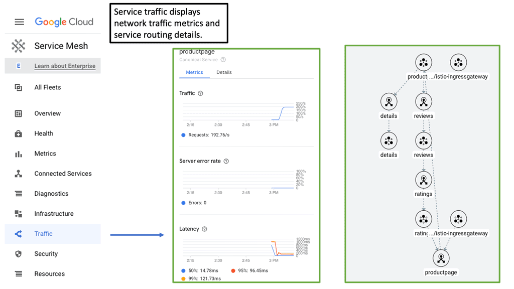
Ratio load balancing 

In this case, Ratio load balancing can distribute traffic unevenly based on predefined ratios. For example, Ratio 3 is assigned to servers 1 and 2, and Ratio 1 is assigned to servers 3. This configuration results in that for every 1 packet assigned to server 3, both servers 1 and 2 will get 3. Initially, it starts with a round-robin, but subsequent flows are differentiated based on the ratios.

A feature known as priority-based member activation allows you to configure pool members into priority groups. High priority gets more traffic. For example, you group the two high-spec servers (server 1 and server 2) in a high-priority group and a low-spec server (server 3) in a low-priority group. The old server will not be used unless there is a failure in priority group 1.

F5 full proxy architecture: Health and performance monitors

Health and performance monitors are associated with a pool to determine if servers are operational and can receive traffic. The type of health monitor used depends on the type of traffic you want to monitor. There are several predefined monitors, and you can customize your own. For example, LTM attempts FTP to download a specified file to the /var/tmp directory, and the check is successful if the file is retrieved.

Some HTTP monitors permit the inclusion of a username and password to retrieve a page on the website. You also have LDAP, MYSQL, ICMP, HTTPS, NTP, Oracle, POP3, Radius, RPC, and many others. iRules allows you to manage traffic based on business logic. For example, you can direct customers to the correct server based on language preference in their browsers. An iRule can be the trigger to inspect this header (accept-language) and select the right pool of application servers based on the value specified in the header.

Increase backend server performance.

It says computationally it is more exhausting to set up a new connection rather than receive requests over an existing OPEN connection. That’s HTTP keepalives invented and made standard in HTTP v1. LTM has a “One connect” feature that leverages HTTP keepalives to reuse connections for multiple clients, not just a single client. It works with HTTP keepalives to make existing connections available for other clients, not just a single client. Fewer open connections means lower resource consumption per server.

When the LTM receives the HTTP request from the client, it makes the load-balancing decision before the “One connect” is considered. If there are no OPEN or IDLE server-side connections, the BIP-IP creates a new TCP connection to the server. When the server responds with the HTTP response, the connection is left open on the BIP-IP for reuse. The connection is held in a table buffer called the connection reuse pool.

New requests from other clients can reuse the OPEN IDLE connection without setting up a new TCP connection. The source mask on the OC profile determines which clients can reuse open and idle server-side connections. Using SNAT, the source address is translated before applying the OC profile.

Closing Points on Full Proxy

To appreciate the advantages of full proxy, it’s essential to understand how it differs from a traditional proxy setup. A traditional proxy server forwards requests from clients to servers and vice versa, acting as a conduit without altering the data. In contrast, a full proxy terminates the client connection and establishes a separate connection with the server. This distinction allows full proxies to inspect and modify requests and responses, offering enhanced security, optimization, and control over traffic.

Load balancing is a critical component of network management, ensuring that no single server becomes overwhelmed with requests. Full proxy architecture excels in this area by providing intelligent traffic distribution. It can analyze incoming requests, evaluate server health, and distribute workloads accordingly. This dynamic management not only improves server efficiency but also enhances user experience by reducing latency and preventing server downtime.

Another significant advantage of full proxy is its ability to bolster network security. By terminating the client connection, full proxies can inspect incoming traffic for malicious content before it reaches the server. This inspection enables the implementation of robust security measures such as SSL/TLS encryption, DDoS protection, and web application firewalls. Consequently, businesses can safeguard sensitive data and maintain compliance with industry regulations.

Full proxies offer a suite of tools to optimize network performance beyond load balancing. Features like caching, compression, and content filtering can be implemented to improve data flow and reduce unnecessary network strain. By caching frequently requested content, full proxies reduce the load on backend servers, accelerating response times and enhancing overall efficiency.


Summary: Full Proxy

In today’s digital age, connectivity is the lifeblood of our society. The Internet has become an indispensable tool for communication, information sharing, and business transactions. However, numerous barriers still hinder universal access to the vast realm of online resources. One promising solution that has emerged in recent years is the concept of fully proxy networks. In this blog post, we delved into the world of fully proxy networks, exploring their potential to revolutionize internet accessibility.

Understanding Fully Proxy Networks

Fully proxy networks, or reverse proxy networks, are innovative systems designed to enhance internet accessibility for users. Unlike traditional networks that rely on direct connections between users and online resources, fully proxy networks act as intermediaries between the user and the internet. They intercept user requests and fetch the requested content on their behalf, optimizing the delivery process and bypassing potential obstacles.

Overcoming Geographical Restrictions

One of the primary benefits of fully proxy networks is their ability to overcome geographical restrictions imposed by content providers. With these networks, users can access websites and online services that are typically inaccessible due to regional limitations. By routing traffic through proxy servers located in different regions, fully proxy networks enable users to bypass geo-blocking and enjoy unrestricted access to online content.

Enhanced Security and Privacy

Another significant advantage of fully proxy networks is their ability to enhance security and privacy. By acting as intermediaries, these networks add an extra layer of protection between users and online resources. The proxy servers can mask users’ IP addresses, making tracking their online activities more challenging for malicious actors. Additionally, fully proxy networks can encrypt data transmissions, safeguarding sensitive information from potential threats.

Accelerating Internet Performance

In addition to improving accessibility and security, fully proxy networks can significantly enhance internet performance. By caching and optimizing content delivery, these networks can reduce latency and speed up web page loading times. Users can experience faster and more responsive browsing experiences, especially for frequently accessed websites. Moreover, fully proxy networks can alleviate bandwidth constraints during peak usage periods, ensuring a seamless online experience for users.

Conclusion:

Fully proxy networks offer a promising solution to the challenges of internet accessibility. By bypassing geographical restrictions, enhancing security and privacy, and accelerating internet performance, these networks can unlock a new era of online accessibility for users worldwide. As technology continues to evolve, fully proxy networks are poised to play a crucial role in bridging the digital divide and creating a more inclusive internet landscape.

businessman drawing colorful light bulb with IPV6 abbreviation, new technology idea concept

IPv6 Fragmentation

IPv6 Fragmentation

In the vast landscape of networking and internet protocols, IPv6 stands as a crucial advancement. With its expanded address space and improved functionality, IPv6 brings numerous benefits. However, one aspect that requires attention is IPv6 fragmentation. In this blog post, we will dive deep into the intricacies of IPv6 fragmentation, explore its significance, and discuss how to navigate this aspect effectively.

Before we delve into fragmentation in IPv6, along with the details of the IPv6 fragment and an IPv6 fragmentation example, let us start with the basics. IPv6 fragmentation divides an IPv6 packet into smaller packets to facilitate transmission across networks with a smaller Maximum Transmission Unit (MTU). Unlike IPv4, fragmentation is not mandatory in IPv6, as all networks support an MTU of at least 1280 bytes.

However, fragmentation may still be necessary. When a packet is fragmented, the original packet is divided into smaller pieces, known as fragments. Each fragment contains a portion of the original packet and additional information that allows the receiving device to reassemble the packet correctly.

IPv6 fragmentation refers to the process of breaking down IPv6 packets into smaller units, known as fragments, to accommodate varying network MTU (Maximum Transmission Unit) sizes. Unlike IPv4, IPv6 relies on the source device instead of intermediary routers for fragmentation. This shift has implications on network performance, security, and overall efficiency.

Highlights: IPv6 Fragmentation

**Understanding IPv6 and Its Importance**

In the rapidly evolving landscape of the internet, IPv6 stands as a beacon of progress and innovation. With IPv4 addresses running scarce, the introduction of IPv6 brings a virtually limitless pool of IP addresses, ensuring the continued growth and expansion of the internet. But beyond the numbers, IPv6 also introduces new features and enhancements that improve the efficiency and security of data transmission. One significant aspect, which we’ll explore in this blog post, is IPv6 fragmentation.

**What is IPv6 Fragmentation?**

Fragmentation in network communication refers to the process of breaking down a large data packet into smaller pieces to ensure it can be transmitted across networks that cannot handle the original size. Unlike its predecessor, IPv4, where routers along the path could fragment packets, IPv6 requires the sending device to perform this task. This shift in responsibility is designed to optimize network performance and reduce the burdens on intermediate routers.

**How IPv6 Fragmentation Works**

In IPv6, fragmentation is handled exclusively by the source node. When a large packet is sent, it is up to the source to determine the path’s maximum transmission unit (MTU) and fragment the packet accordingly. This process ensures that packets are transmitted without causing congestion or packet loss due to size limitations. Once fragmented, these packets are reassembled by the destination node, not by routers along the way, which streamlines the transmission process.

**The Impact of Fragmentation on Network Security**

While IPv6 fragmentation offers efficiency, it also brings new challenges in terms of security. Fragmented packets can be exploited by attackers to bypass security measures, leading to potential vulnerabilities such as Denial of Service (DoS) attacks. Network administrators must implement robust security protocols to inspect and verify fragmented packets accurately, ensuring that malicious activities are detected and mitigated.

**Best Practices for Handling IPv6 Fragmentation**

To effectively manage IPv6 fragmentation, organizations should adopt a set of best practices. These include configuring devices to avoid unnecessary fragmentation, setting appropriate MTU sizes, and employing advanced security measures to monitor and analyze fragmented traffic. Regular updates to network security systems are also vital to keep up with evolving threats related to fragmentation.

IPv6 Fragmentation 

A: ) Fragmentation in IPv6 can occur at either the source or destination device. The source device may fragment packets if it determines that the packet size is larger than the MTU of a network along the path to the destination. Alternatively, the destination device may request that the source device fragment a packet if the packet size exceeds the MTU of the local network.

B: ) In IPv4 and IPv6, end hosts have never been able to determine the maximum payload size when communicating with remote hosts through the IP protocol stack. IP packets are routed independently from each other and can take different routes with different MTU sizes, so a network-wide MTU mechanism is not necessary. Nevertheless, the absence of end-to-end information can lead to oversized packets being received by intermediate routers, which cannot forward them.

C: ) A convenient solution to this problem is provided by the IPv4 and IPv6 protocols: IP fragmentation, which splits a single inbound IP datagram into two or more outbound IP datagrams. It is done by copying the IP header from the original IP datagram into the fragments, setting special bits to indicate that the fragments are not complete IP packets (IPv6 uses extension headers), and spreading the payload across the fragments. As opposed to IPv4, IPv6 does not support fragmentation during transit – if fragmentation is needed, the sending host must do it.

Factors Influencing Fragmentation

Several factors can influence IPv6 fragmentation. First and foremost is the network’s MTU size. Each network has its own MTU; fragmentation becomes necessary when a packet exceeds this size. Additionally, path MTU discovery plays a crucial role in determining whether fragmentation is required along the network path. Understanding these factors is essential for effectively handling fragmentation-related challenges.

**Impact on Network Performance**

Fragmentation can have a notable impact on network performance. When packets are fragmented, additional processing overhead is introduced on both the source device and the recipient. This can lead to increased latency, reduced throughput, and potential performance bottlenecks. Minimizing fragmentation and optimizing MTU settings is crucial to ensure optimal network performance.

**Addressing Security Concerns**

IPv6 fragmentation also introduces security considerations. Fragmentation-based attacks, such as fragmentation overlap, can exploit vulnerabilities and impact network security. Proper security measures, including fragmentation detection and prevention mechanisms, must be implemented to mitigate potential risks.

**Best Practices for IPv6 Fragmentation**

Navigating IPv6 fragmentation requires a proactive approach and adherence to best practices. Some key recommendations include optimizing network MTU sizes, enabling path MTU discovery mechanisms, implementing firewall rules to detect and prevent fragmented packets, and staying updated with the latest security practices.

Knowledge Check: Troubleshoot with Traceroute

### How Traceroute Works

To understand how traceroute functions, you need to know a bit about how data packets work. When you send a request to access a website, your data is broken into small packets that traverse the internet. Traceroute sends a series of these packets to the destination while incrementally increasing the time-to-live (TTL) value. Each router along the path decrements the TTL by one before passing the packet along. When the TTL reaches zero, the router returns an error message to the sender. By analyzing these error messages, traceroute compiles a list of routers the packets passed through.

### Applications and Benefits of Traceroute

Traceroute is not only a fascinating tool for network enthusiasts but also an essential utility for network administrators. By revealing the path data takes, it helps in diagnosing network slowdowns, identifying bottlenecks, and uncovering routing inefficiencies. Traceroute can also assist in uncovering potential security vulnerabilities by highlighting unexpected routes or unknown servers that data might be passing through.

IPv6 Fragmentation: IPv6 Source Only

– Unlike IPv4, an IPv6 router does not fragment a packet unless it is the packet’s source. Intermediate nodes (routers) do not fragment. The fields used in IPv4 headers for fragmentation do not exist in IPv6 headers. You will see how an IPv6 device fragments packets when it is the source of the packet with the use of extension headers.

– An IPv6 router drops packets too large for the egress interface and sends an ICMPv6 Packet Too Big message back to the source. Packet Too Big messages include the link’s MTU size in bytes so the source can resize the packet.

– Data is usually transmitted as a series of packets, sometimes called a packet train. Larger packets may require fewer packets to be transmitted. Therefore, using the largest packet size supported by all the links from the source to the destination is preferable.

– Path MTUs (PMTUs) are used for this purpose. Devices can use Path MTU discovery to determine the minimum link MTU along a path. RFC 1981, Path MTU Discovery for IP Version 6, suggests that IPv6 devices should perform ICMPv6 PTMU discovery to avoid source fragmentation.

Drawbacks of Fragmentation

IP fragmentation always increases layer-3 overhead (and user bandwidth is reduced). For example, if an end-host thinks it can use 1500-byte IP packets, but there is a hop in the path with MTU size 1472, each oversized IP packet will be split into two packets, resulting in two additional 20-byte IPv4 headers or 40-byte IPv6 headers.

Furthermore, application-layer information isn’t copied into all non-first IP fragments since the TCP or UDP headers aren’t copied. It has been widely used to break firewalls using overlapping fragments, where the second fragment rewrites the TCP/UDP header from the first fragment. Consequently, some firewalls might drop IP fragments (resulting in blocked communication between end hosts).

Reassembling fragments and inspecting their contents consumes additional CPU resources. To detect intrusion signatures effectively, intrusion detection and prevention systems (IDS/IPS) must provide similar functionality. IPv6’s unlimited extension header chains exacerbated the problem.

Related: For pre-information, before you proceed, you may find the following IPv6 information of use:

  1. IPv6 Host Exposure
  2. IPv6 RA
  3. 6LoWPAN Range
  4. Docker Security Options
  5. Technology Insight for Microsegmentation
  6. Dead Peer Detection

IPv6 Fragmentation

IPv6 fragmentation Process:

IPv6 fragmentation is a process that divides large IPv6 packets into smaller fragments to facilitate their transmission over networks with a smaller maximum transmission unit (MTU) size. This is necessary because not all networks can handle the full packet size of IPv6, which is 1280 bytes.

IPv6 fragmentation occurs at the source node, dividing the original packet into smaller fragments. Each fragment contains a fragment header that includes information such as the offset of the fragment within the original packet, a flag indicating whether more fragments are expected, and the identification number of the original packet.

When they reach their destination, the fragments are reassembled into the original packet by the destination node. The fragments are identified using the identification number in the fragment header, and the offset information is used to determine the correct order of the fragments. However, IPv6 fragmentation should be avoided whenever possible, as it can introduce additional overhead and processing delays.

Fragmentation can also affect network performance and reliability. To minimize fragmentation, IPv6 nodes should be configured with an appropriate MTU size that can accommodate the most extensive packets they are likely to encounter.

Fragment Attacks ( DDoS )

Fragmented packets can fool a firewall into allowing otherwise prohibited traffic. The firewall must be capable of enforcing its filtering policy on fragmented packets. For this to work, the firewall must find the complete header data set, including extension headers and protocol/port values at the upper layer. Additionally, the packet must not be susceptible to fragment overlap attacks. Since extension headers can push upper-layer protocol/port information outward (toward packet boundaries), fragment overlaps are a more severe problem in IPv6 than in IPv4.

Path MTU Discovery

In addition, IPv6 nodes can use the Path MTU Discovery (PMTUD) mechanism to dynamically determine the maximum MTU size along the path to a destination. PMTUD sends packets with the “Don’t Fragment” (DF) flag set and progressively reduces the packet size until a smaller MTU is found. Once the maximum MTU size is determined, the source node can adjust its packet size accordingly to avoid fragmentation.

While IPv6 fragmentation is a valuable mechanism for ensuring packet delivery over networks with smaller MTU sizes, it should be used sparingly. Minimizing the need for fragmentation through proper MTU configuration and utilizing PMTUD can help improve network performance and reliability.

IPv6 path mtu discovery

Example: Fragmentation in IPv6.

The following screenshot is taken from my Cisco modeling labs. We have a small network of three routers: R7, iosv-o, and R1. These routers are IPv6 enabled with the command IPv6 unicast-routing and the command IPv6 enabled under the corresponding interfaces, along with IPv6 addressing. The middle router, “iosv-o,” acts as an IPv6 interconnection point, and I lowered the IPv6 MTU here. An extended ping was initiated from R7 to R1 with a large datagram size.

IPv6 fragmentation: R1 receives an ICMPv6: Received Too Big, and the interconnection router is responsible for sending the ICMPV6: Sent Too Big. The intended destination does not get involved, preserving resources on R1.

As you can see from the screenshot below. An IPv6 router cannot fragment an IPv6 packet, so if the packet is too large for the next hop, the router is required to generate an ICMP6 Type 2 packet addressed to the source of the packet with a Packet Too Big (PTB) code and also providing the MTU size of the next hop.

While an IPv6 router cannot perform packet fragmentation, the IPv6 sender may fragment an IPv6 packet at the source. So, keep in mind that we lost the first ping. Subsequent packets will get through once the fragmentation has been performed at the source after receiving the packet’s big message.

IPv6 fragmentation example
Diagram: IPv6 fragmentation example

Knowledge Check: ICMPv6

Before we get to the first lab guide, I’d like to do a knowledge check on ICMPv6. ICMPv6, an integral part of the IPv6 protocol suite, is a communication protocol between network devices. It primarily handles network error reporting, congestion feedback, and diagnostic functions. Unlike its predecessor, ICMP for IPv4, ICMPv6 offers several additional features, making it an essential component of modern network infrastructures.

Key Functionalities of ICMPv6

ICMPv6 encompasses a range of functionalities that contribute to the smooth functioning of IPv6 networks. From Neighbor Discovery Protocol (NDP) to Path MTU Discovery (PMTUD) and Router Advertisement (RA), each feature plays a crucial role in maintaining efficient communication and connectivity. Let’s explore these functionalities in detail.

The Role of ICMPv6 in Network Troubleshooting

ICMPv6 proves to be a valuable tool in network troubleshooting. ICMPv6 helps network administrators identify and resolve issues promptly by providing error reporting mechanisms. From unreachable hosts to time-exceeding messages, ICMPv6 messages offer valuable insights into network connectivity problems, aiding in efficient problem resolution.

Security Considerations and Best Practices

While ICMPv6 is a vital protocol, it is not immune to security vulnerabilities. Network administrators must implement proper security measures to protect their networks from threats. This section will highlight some recommended security practices and considerations when dealing with ICMPv6, ensuring a secure and reliable network environment.

Guide: ICMPv6 IPv6

In the following, I have enabled IPv6 on only one router – IOSv-1. I have not configured any specific IPv6 IP configuration, so we have the link-local addresses that come by default when you enable IPv6 on an interface. Once I enabled IPv6 on the interface, I ran a debug ipv6 icmpv6. Notice we are sending icmpv6 router advertisements.

ICMPv6 Router Advertisement (RA) is a critical component of the Neighbor Discovery Protocol (NDP) in IPv6. Its primary function is to allow routers to inform neighboring devices about their presence and configuration parameters.

Routers periodically send RA messages to all nodes on a local network, providing critical information for automatic address configuration and maintaining network connectivity. However, we don’t receive any RA messages because IPv6 is not enabled in other network parts.

ICMPv6
Diagram: Lab guide on ICMPv6 debug

ICMPv6 Security

Layer 2 was designed with a plug-and-play approach; connect a switch, and it simply works. This ease often causes people to forget security and securing the switched infrastructure. Compromising a network at layer 2 can affect traffic at all layers above it. Once layer 2 is compromised, it is easier to launch man-in-the-middle attacks for secure upper-layer protocols such as Secure Sockets Layer ( SSL ) and Secure Shell ( SSH ).

When discussing IPv6, why concern ourselves with layer two security?IPv6 is IP and operates at Layer 3, right?

IPv6 has to discover other adjacent IPv6 nodes over layer 2. It uses Neighbor Discovery Protocol ( NDP ) to discover IPv6 neighbors, and NDP operates over ICMPv6, not directly over Ethernet, unlike Address Resolution Protocol ( ARP ) for IPv4.

ICMPv6 offers functions equivalent to IPv4 ARP and additional functions such as SEND ( Secure Neighbor Discovery ) and MLD ( Multicast Listener Discovery ). If you expand layer 2 and adjacent IPv6 hosts connect via layer 2 switches and not layer 3 routers, you will face IPv6 layer 2 first-hop security problems.

Of course, if you have a “properly” configured network, use layer 2, which should only be used for adjacent node discovery. The first hop could then be a layer 3 switch, which removes IPv6 layer 2 vulnerabilities. For example, the layer 3 switches cannot listen to RA messages and could also provide uRFP to verify the source of IPv6, mitigating IPv6 spoofing.

ICMP and ICMPv6

The Internet Control Messaging Protocol ( ICMP ) was initially introduced to aid network troubleshooting by providing tools to verify end-to-end reachability. ICMP also reports back errors on hosts. Unfortunately, due to its nature and lack of built-in security, it quickly became a target for many attacks. For example, an attacker can use ICMP REQUESTS for network reconnaissance.

ICMP’s lack of inherent security opened it up to some vulnerabilities. This results in many security teams blocking all ICMP message types, which harms useful ICMP features such as Path MTU. ICMP for v4 and v6 are entirely different. Unlike ICMP for IPv4, ICMPv6 is an integral part of v6 communication, and ICMPv6 has features required for IPv6 operation. For this reason, it is not possible to block ICMPv6 and all its message types. ICMPv6 is a legitimate part of V6; you must select what you can filter. ICMPv6 should not be completely filtered.

ICMPv6 and Hop Count

Most ICMPv6 messages have their hop count set to 255, with the exemption on PMTU and ICMPv6 error messages. This means that any device that receives an ICMPv6 message with a max hop count of less than 255 should drop the packet as crafted by an illegal source. By default, ICMPv6 with hop count of 255 messages are dropped at layer 3 boundaries. This is used as a loop prevention mechanism.

The default behavior can cause security concerns. For example, if a FW received an ICMPv6 packet with a hop count of 1. By default, it decrements the hop count and sends back an ICMPv6 time exceeded. If a firewall follows this default behavior, an attacker could be overwhelmed by many packets with TTL 1. Potential DoS attack the firewall device.

Prevent ICMPv6 Address Spoofing

The best practice is to check the source and destination address in an ICMPv6 packet. For example, in MLD ( Multicast Listener Discovery ), the source should always be a link-local address. If a check proves that this is not the case, it is likely that the packet originated from an illegal source and should be dropped.

You may also block any ICMPV6 address not assigned by the IANA. However, this is a manual process, and ACL adjustments are made whenever IANA changes the list.

Try hardening your device by limiting the number of ICMPv6 error messages. This will prevent a DoS attack by an attacker sending a barrage of malformed packets requiring many ICMPv6 error messages. – ipv6 icmp error interval.

Back To: The fragmentation process

The IP protocol stack needs a reliable mechanism where the end hosts can figure out the maximum payload size to use when communicating across a network to a remote IPv6 host. So, we end up with the absence of a network-wide mechanism. Destination-based routing results in IP packets being routed independently of each other. Each router in the paths decides where to route the packet.

As a result, we have different packets between the same end hosts that could take different routes with varying MTU sizes. The primary issue is that the need for end-to-end information can quickly result in oversized packets being received by intermediate routers that cannot be sent onward. To overcome this, we have a process known as IP fragmentation that comes into play, and we have this for IPv4 and IPv6 networks.

IP fragmentation
Diagram: IP Fragmentation. The source is Imperva.

**Fragmentation is normal**

Fragmentation is a normal process on packet-switched networks. It occurs when a large packet is received, and the corresponding outbound interface’s maximum transmission unit (MTU) size is too small. Fragmentation dissects the IP packet into smaller packets before transmission. The receiving host performs fragment reassembly and passes the complete IP packet up the protocol stack.

Fragmentation is an IP process; TCP and other layers above IP are not involved. Reassembly is intended in the receiving host, but in practice, it may be done by an intermediate router. For example, network address translation (NAT) may need to reassemble fragments to translate data streams. This is where some differences between fragmentation in IPv4 and IPv6 are apparent.

In summary, IP fragmentation occurs at the Internet Protocol (IP) layer. Packets are fragmented to pass through a link with a smaller maximum transmission unit (MTU) than the original packet size. The receiving host then reassembles the fragments.

Impact on networks

In networks with multiple parallel paths, technologies such as LAG and CEF split traffic according to a hash algorithm. All packets from the same flow are sent out on the same path to minimize packet reordering. IP fragmentation can cause excessive retransmissions when fragments encounter packet loss. This is because reliable protocols such as TCP must retransmit all fragments to recover from the loss of a single fragment.

Senders typically use two approaches to determine the IP packet size to send over the network. In the first case, the sending host sends an IP packet equal to the MTU of the first hop of the source-destination pair. Secondly, the Path MTU Discovery algorithm can determine the path MTU between two IP hosts to prevent IP fragmentation.

**Fragmentation in IPv4 and IPv6**

A: ) Fragmentation in IPv6 is splitting a single inbound IP datagram into two or more outbound IP datagrams. The IP header is copied from the original IP datagram into the fragments. With IPv6, special bits are set in the fragments’ IPv6 headers to indicate that they are not complete IP packets. In the case of IPv6, we use IPv6 extension headers. Then, the payload is spread across the fragments.

B: ) In IPv4, fragmentation is done whenever required, at the destination or routers, whereas, in IPv6, only the source, not the routers, is supposed to do fragmentation. This can only be done when the source knows the Maximum Transmission Unit (MTU) path.

C: ) The IPv6 “do not fragment” bit is always 1, whereas the case is not the same in IPv4, and the ‘More fragment’ bit is the only flag in the fragmentation header, which is one bit. Two bits are reserved for future use, as shown in the picture below. The following diagram displays the Internet Protocol Version 6 Fragmentation Header.

Internet Protocol Version 6 Fragmentation Header
Diagram: Internet Protocol Version 6 Fragmentation Header

IPv6 Fragmentation Header

  • Next Header –
    The Next Header is an 8-bit field that identifies the type of header present after Fragmentation header.

  • Reserved –
    It is an 8-bit field which is completely zero as of now. In future, we might find something useful to fill here. Also again an extra 2-bit field is reserved for later purposes.

  • Fragment Offset –
    It is exactly the same as in IPv4 which is of size 13 bits. Just as we did to scale up fragment offset in IPv4 we will do same in IPv6.

  • More Fragment (M) –
    More fragment bit in here is denoted by “M”. It’s a one-bit field that tells us if there are more fragments coming after it. If more fragment bit is zero then it means its the last fragment and if 1 then it could be any packet except being last one.

  • Identification Number –
    The identification number field which is the same for all fragments of a particular packet is double in size as that of in IPv4. In packet identifier field is of 32 bits and In IPv4 it was of 16 bits.

In an IPv4 world, several flags and fields control fragmentation, including the Fragment Offset, Don’t Fragment (DF) bit, and More Fragments (MF) flags. All fragmentation information is contained in the IPv4 header. The fragment offset tells the receiving device exactly where the fragment should be placed in the overall message. The DF bit tells hosts not to fragment. 

If set, packets are dropped, and fragmentation along the path is required. This mechanism is used for Path MTU Discovery to determine the maximum MTU size on the network. It is set automatically with host software or manually with command-line tools. Finally, when an IP packet undergoes fragmentation, the MF bit is set for all datagrams except the last one. For unfragmented packets, the MF flag is cleared.

Path MTU
Diagram: Path MTU. The source is Packetlife.

In IPv4 networks, when a router receives a network packet more significant than the next hop’s MTU, it has two options: either drop the packet if the Don’t Fragment (DF) flag bit is set and send an Internet Control Message Protocol (ICMP) message indicating Fragmentation Needed (ICMP Type 3 and ICMP Code 4), or fragment the packet and send it on the link with a smaller MTU. Despite originators producing fragmented packets, IPv6 routers cannot fragment further. Therefore, IPv6 hosts must determine the optimal MTU using Path MTU Discovery before sending packets, rather than network equipment delivering IPv6 packets or fragments smaller than or equal to 1280 bytes.

Guide: IPv6 fragmentation

In the following lab setup, we have a three-router node design. The 2911 routers are running IPv6, and I have enabled IPv6 RIP for reachability. The 2960 switch has its out-of-the-box configuration, so everything is in the default VLAN, and MAC address learning is working. One difference is that the MTU has been set to 1280 Bytes, as shown below. Running an extended ping with a higher MTU, we get an ICMPv6 packet that is too big a message. As a test, you can put an IPv6 access list inbound on Router0, tracking the ICMPv6 packet with too many big messages.

ipv6 fragmentation example
Diagram: IPv6 Fragmentation Example
  • Question: What is Path MTU Discovery (or PMTUD)

A PMTUD is a mechanism used on the Internet to determine how large packets can be transmitted to a specific destination. Here’s how it works: Your host will send a potentially large packet marked “Do Not Fragment.” Then, whenever a router cannot forward a packet due to its size, it responds with, “Too big! Try this size instead.”

  • Question: How does this relate to IPv6?

All IPv6 packets are “Do Not Fragment.” Routers no longer have to send the correct-sized packets; this is expensive. A significant difference between fragmentation in IPv4 and IPv6 is that IPv6 instead mandates PMTUD.

  • Question: What does the firewall need to allow?

To work correctly on the public Internet, IPv6 firewalls must allow ICMPv6, type 2 (Packet Too Big). Therefore, if you implement an IPv6 firewall for your website, enterprise, or other organization, you should permit this specific ICMPv6 message.

The final difference between IPv4 and IPv6 fragmentation

IPv4 hosts must use their best efforts to reassemble fragmented IP packets up to 576 bytes in size. They may also attempt to reassemble fragmented IP packets larger than 576 bytes, but these larger packets may be silently discarded. Therefore, applications should only send packets larger than 576 bytes if they know the remote host can accept or reassemble them.

In IPv6, hosts must try to reassemble fragmented packets with a total reassembled size of up to 1500 bytes. This is because IPv6 has a minimum MTU of 1280 bytes. Fragmented packets more significant than 1500 bytes are silently discarded. The packet must be explicitly fragmented at the origin for IPv6 applications to overcome path MTU limitations. However, unless the remote host can reassemble, they should not attempt to send fragmented packets with a total size exceeding 1500 bytes. Now that we understand the difference between IPv4 and IPv6 fragmentation, let’s focus on IPv6.

Fragmentation in IPv6

A – ) The IPv6 sender may perform fragmentation at the source because an IPv6 router cannot perform fragmentation. Therefore, if the packet is too large for the next hop router, the router will generate an ICMP packet to inform the sending source that the packet is too large. The fragmentation header tries to minimize fragmentation as much as possible by supporting a minimum packet size of 1280 Bytes

B – ) IPv6 and other extension headers are unfragmentable because every fragment has to go through nodes or routers, and at every router, information stored in these extension headers is required. That is why the IPv6 packet is divided into two parts. The diagram below shows that one is an unfragmentable part, and the other is fragmentable. The unfragmentable part does not encounter any modification in between, and another part is fragmentable and is divided into many small fragments such as fragment 1, fragment 2, and so on.

C – ) After creating small fragments, the fragmentation header and particular fragments (such as fragment 1 ) are connected to the unfragmentable part and sent to the destination. Payload length may change after fragmentation, and the header is added after fragmentation. Corresponding fields, such as header, identification number, fragment offset, and more fragment bits, are filled out appropriately. We will discuss this in more detail in just a moment.

Fragmentation in IPv6
Diagram: Fragmentation in IPv6.

Fragmentation in IPv6: A source of security vulnerabilities

Fragmentation has been a frequent source of security vulnerabilities in IPv4, and for a good reason. With fragmented IPv4 packets, the layer 4 header information is unavailable in the second through the last fragment.

As a result, fragmentation and fragment reassembly can create unexpected and harmful behaviors in an intermediate node. The process of fragmentation in networks can lead to IP security issuesFragmentation can be exploited for various attacks, such as fingerprinting, IPS insertion/evasion, firewall evasion, and remote code execution. As we move to IPv6, are we exposed to the same type of attacks?

fragmentation in IPv6
Diagram: IPv6 fragmentation.

Security Risks: IPv6 Virtual Reassembly

The issue of non-initial fragments

Due to the lack of the L4 header, usually only available on the initial fragment of a fragmented IPv6 packet, non-initial fragments pass through IPsec and NAT64 without examination. The IPv6 Virtual Fragmentation Reassembly (VFR) feature collects fragments and provides L4 info for all fragments for IPsec and NAT64 features.

Most non-initial fragments do not have a Layer 4 header, as it usually travels with the initial fragments (except for micro-fragmentation and tiny fragments). Therefore, some features (such as NAT, Cisco IOS XE Firewall, and IPSec) cannot gather port information from packets. To check the Layer 7 payload, these features may need to reassemble and refragment the fragments.

The use of IPv6 virtual fragmentation reassembly

VFR works with any feature that requires fragment reassembly (such as Cisco IOS XE Firewall, NAT, and IPSec). VFR is automatically enabled on Cisco IOS XE Firewalls, Crypto-based IPSecs, NAT64s, and onePK interfaces whenever these features are present.

If more than one feature attempts to enable VFR automatically on an interface, VFR maintains a reference count to keep track of the number of features that have enabled VFR. When the reference count is reduced to zero, VFR is automatically disabled.

For information on layers 4 or 7, virtual fragmentation reassembly (VFR) is automatically enabled by some features (such as NAT, Cisco IOS XE Firewall, and IPSec). The Cisco IOS XE Firewall can use VFR to create dynamic access control lists (ACLs) to prevent fragmentation attacks.

Guide: IPv6 Virtual Reassembly

The following guide shows our options for enabling IPv6 virtual-reassembly. We have in, out, and percentage values. With the command show IPv6 virtual-reassembly, notice the default value.

IPv6 virtual fragmentation reassembly

IPv6 fragmentation example

In an IPv6 world, the IPv6 header length is limited to 40 bytes, yet the IPv4 header has a max of 60. The primary IPv6 header remains a fixed size. IPv6 has the concept of extension headers to add optional IP layer information. Special handling with IPv4 was controlled by “IP options,” but there are no IP options in IPv6. All options are moved to different types of extension headers.

The IPv6 option mechanism is improved over the IPv4 option mechanism. In a packet, IPv6 options are placed in extension headers between the IPv6 header and the transport-layer header. In most cases, IPv6 extension headers are only examined or processed once the packet reaches its final destination. This feature has greatly improved the performance of routers containing options. An IPv4 router must explore all options in the presence of any option.

Unlike IPv4 options, IPv6 extension headers can be of arbitrary length. Also, the number of options a packet carries is not limited to 40 bytes. This feature permits IPv6 options to be used for functions not practical in IPv4. A suitable example of IPv6 options is IPv6 authentication and security encapsulation options.

The following IPv6 extension headers are currently defined.

  • Routing – Extended routing, like IPv4 loose source route
  • Fragmentation – Fragmentation and reassembly
  • Authentication – Integrity and authentication, security
  • Encapsulation – Confidentiality
  • Hop-by-Hop Option – Special options that require hop-by-hop processing
  • Destination Options – Optional information to be examined by the destination node

We now have a fragment header that governs fragmentation. The fragment header contains information that helps the receiving host reassemble the original IP packet.

The IPv6 fragment header

With IPv4, all this was contained in the IPv4 header. There is no separate fragment header in IPv4, and the fragment fields in the IPv4 header are moved to the IPv6 fragment header. The “Don’t fragment” bit (DF) is removed, and intermediate routers are not allowed to fragment. They only permitted end stations to create and reassemble fragments (RFC 2460)not intermediate routers. The design decision stems from the performance hit that fragmentation imposes on nodes.

Routers are no longer required to perform packet fragmentation and reassembly, making dropped packets more significant than the router’s interface MTU. Instead, IPv6 hosts perform PMTU to determine the maximum packet size for the entire path. When a packet hits an interface with a smaller MTU, the routers send back an ICMPv6 type 2 error, known as Packet Too Big, to the sending host. The sending host receives the error message, reduces the size of the sending packet, and tries again.

IPv6 Fragmentation Example

Let us look at a quick IPv6 fragmentation example. For illustration purposes, let us keep the numbers simple. We have an IPv6 datagram that is precisely 370 bytes wide. The IPv6 datagram consists of a 40-byte IP header, four 30-byte extension headers, and 210 bytes of data. Two of the extension headers are unfragmentable, while two are fragmentable.

We must send this over a link with an MTU of only 230 bytes. Three fragments, not the two you might expect, are required because each fragment must contain the two 30-byte unfragmentable extension headers and be a length multiple of 8. In this IPv6 fragmentation example, a 370-byte IPv6 datagram containing four 30-byte extension headers is broken into three fragments.

Fragmentation Security Concerns

When examining an IPv6 fragmentation example, one of the main issues is that the first fragment may not have the required upper-layer (TCP and UDP) information. Security devices require this information to determine if the packet complies with its configured policies and rules. Fragmentation can obfuscate the data, allowing it to pass security devices. Routers and non-stateful devices usually only look at the first fragment containing the header information.

Many small fragments are used to hide or DoS attack a node. The attacker dissects the packet into many small fragmented packets, bypassing security devices. Every small fragment looks legitimate, but once reassembled, the entire packet is used to launch an attack. The attacker is hiding his real intention by pushing the contents of the attack into many small fragments. These might be passed and unseen by devices that only look at the unfragmented part.

ipv6 fragmentation

Types of IPv6 attacks

1. Neighbor Discovery Protocol (NDP) Attacks:

a) The Neighbor Discovery Protocol (NDP) is a crucial component of IPv6, used for address autoconfiguration and neighbor discovery. Attackers can exploit vulnerabilities in NDP to launch various attacks, including:a) Router Advertisements (RA) Spoofing: Attackers can send malicious router advertisements to redirect traffic or perform man-in-the-middle attacks.
b) Neighbor Solicitation (NS) Spoofing: Attackers can gain unauthorized access to the network by impersonating a legitimate device.

2. Denial of Service (DoS) Attacks:

IPv6 networks are susceptible to Denial of Service (DoS) attacks, which aim to disrupt the availability of network resources. Some common DoS attacks targeting IPv6 include:

a) ICMPv6 Flood: Attackers flood the network with ICMPv6 packets, overwhelming network devices and causing performance degradation.
b) Fragmentation Attacks: Attackers exploit vulnerabilities in the IPv6 fragmentation process, causing network devices to spend excessive resources on reassembling fragmented packets.

3. IPv6 Address Spoofing:

IPv6 address spoofing involves forging the source IPv6 address in packets to deceive network devices. This attack can be used for malicious purposes, such as bypassing access control lists, evading intrusion detection systems, or launching reflection attacks.

4. Man-in-the-Middle (MITM) Attacks:

MitM attacks in IPv6 can enable attackers to intercept and manipulate network traffic. Some standard techniques used in MitM attacks on IPv6 networks include:

a) Router Advertisement (RA) Spoofing: Attackers send malicious RAs to redirect traffic through their devices, allowing them to eavesdrop or modify the communication.
b) Address Resolution Protocol (ARP) Spoofing: Attackers manipulate the IPv6-to-MAC address resolution process, intercepting traffic between devices.

Additional IPv6 Attacks:

Other attacks include overlapping fragments, incomplete sets of fragments, fragments inside a tunnel, and nested fragments. Nested fragments are packets with multiple sets of fragment headers, which should never occur in standard IP networks. The source only creates one fragment header. Overlapping fragments can be used for O/S fingerprinting and IPS/IDS evasions.

Fragmentation attacks may be used on DoS, an end host. If hosts cannot process fragmented packets correctly, attackers can send many fragmented packets, which will be processed by kernel memory, exhausting the kernel from processing legitimate fragments. Many tools like Whisker, Fragrouter, and Scapy can craft these packets.

Proper handling of the IPv6 fragment

IPv6 attempts to minimize the use of fragmentation by supporting the minimum IPv6 datagram size of 1280 bytes. The minimum datagram size in IPv4 is 576 bytes (not to be confused with the minimum MTU for both IP versions). This removes the severe restriction on data size we had with IPv4 and should minimize the need for fragmentation.

Antonios Atlasis conducted an “Attacking IPv6 using fragmentation” webinar for Black Hat Europe. It included several O/S such as Ubuntu, FreeBSD, OpenBSD, and W2K7. Scapy, a packet manipulation tool, was used to test if the O/S responded to the tiny IPv6 fragment.

For the Upper-layer protocol, ICMPv6 was used to send Echo Requests. All major O/S accepted tiny fragments and sent an ECHO-REPLY in response to the ECHO REQUEST. Accepting small fragments has consequences unless Deep Packet Inspection (DPI) performs complete IP datagram reassembly before IP forwarding. However, without proper DPI, it could lead to firewall evasion. A similar problem exists with IPv4.

  • Going deep on the RFCs and the IPv6 fragment

RFC 5722 recommends disallowing overlapping fragments. The RFC states that if an IPv6 host performs reassembling and contains a fragment determined to be overlapping, then the entire datagram is silently discarded. No error message is sent back to the sending host. Antonios Atlasis’s test proves that none of the O/S is RFC 5722 compliant.

Like the IPv4 world, IPv6 security features consist of ACL with the “fragments” keyword. The ACL matches the non-initial IPv6 fragment. The initial IPv6 fragment contains the information for Layer 3 and Layer 4. Cisco IOS has a feature known as Virtual Reassembly, which inspects fragmented packets. It is secondary to an input ACL, meaning the input ACL has the first chance to check incoming packets. It reassembles fragmented packets, examines any out-of-sequence fragments, puts them back in proper sequence, and sends up the protocol stack.

Closing Points on IPv6 Fragmentation

Unlike IPv4, where routers along the path could fragment packets, IPv6 introduces a more streamlined approach. In IPv6, only the source node is responsible for fragmenting packets. This shift means that routers are relieved from the burden of processing fragmented packets, thus improving overall network efficiency. With the use of the Fragment Extension Header, IPv6 ensures that packets are reassembled only at the destination, reducing potential points of failure and enhancing security.

IPv6 fragmentation comes with its own set of security considerations. One of the major concerns is the potential for fragmentation-based attacks, such as the Tiny Fragment Attack. By sending multiple small fragments, an attacker could potentially evade detection and carry out malicious activities. To mitigate these risks, network administrators must implement robust security measures, such as deep packet inspection and setting fragmentation thresholds, to identify and block suspicious traffic.

While IPv6’s approach to fragmentation reduces the load on routers, it also has specific performance implications. When a packet is fragmented, each fragment carries overhead, which can lead to increased bandwidth usage. Additionally, if any fragment is lost during transmission, the entire packet must be resent, potentially leading to higher latency. Therefore, optimizing packet sizes and understanding the network’s Path Maximum Transmission Unit (PMTU) are essential steps in maintaining efficient performance.

To effectively manage IPv6 fragmentation, IT professionals should adopt a set of best practices. These include configuring devices to handle large packet sizes, employing PMTU discovery techniques, and regularly monitoring network traffic for anomalies. Additionally, training staff on the nuances of IPv6 can further enhance network resilience and performance.

Summary: IPv6 Fragmentation

In this blog post, we explored the intricacies of IPv6 fragmentation, its significance, and how it impacts our digital experiences.

Understanding IPv6 Fragmentation

IPv6 fragmentation refers to dividing IPv6 packets into smaller units, known as fragments, to facilitate transmission across networks with different maximum transmission unit (MTU) sizes. Unlike IPv4, IPv6 prefers path MTU discovery over fragmentation. However, in specific scenarios, fragmentation becomes necessary to ensure data reaches its destination successfully.

The Need for Fragmentation

Fragmentation is crucial in enabling communication between networks with varying MTU sizes. As data traverses different network segments, it may encounter smaller MTUs, leading to packet fragmentation. Without fragmentation, packets may be dropped or severely delayed, hindering effective data transmission.

Fragmentation Process in IPv6

When fragmentation is required, the sending host breaks the original IPv6 packet into smaller fragments. Each fragment is assigned a Fragment Header, which contains essential information for reassembling the original packet at the receiving end. Upon arrival, the receiving host reassembles the fragments based on the information provided in the Fragment Header.

Section 4: Impact on Performance and Efficiency

While fragmentation ensures data delivery across networks with varied MTU sizes, it can affect performance and efficiency. Fragmentation adds overhead to the network, requiring additional processing power and resources. Excessive fragmentation can lead to increased latency and potential packet loss.

Best Practices for IPv6 Fragmentation

To optimize network performance and reduce the need for fragmentation, it is advisable to adhere to best practices. These include ensuring network devices are configured with appropriate MTU sizes, employing path MTU discovery mechanisms, and utilizing techniques such as TCP Maximum Segment Size (MSS) adjustment to avoid fragmentation whenever possible.

Conclusion:

In the realm of IPv6, fragmentation serves as a vital mechanism for ensuring seamless data transmission across networks with different MTU sizes. Understanding the concept of fragmentation, its significance, and its potential impact on performance empowers network administrators and engineers to optimize their networks and provide efficient connectivity in an IPv6-dominated world.

SSL Security

SSL Security

SSL Security

In today's digital age, ensuring online security has become paramount. One crucial aspect of protecting sensitive information is SSL (Secure Sockets Layer) encryption. In this blog post, we will explore what SSL is, how it works, and its significance in safeguarding online transactions and data.

SSL, or Secure Sockets Layer, is a standard security protocol that establishes encrypted links between a web server and a browser. It ensures that all data transmitted between these two points remains private and integral. By employing a combination of encryption algorithms and digital certificates, SSL provides a secure channel for information exchange.

SSL plays a vital role in maintaining online security in several ways. Firstly, it encrypts sensitive data, such as credit card details, login credentials, and personal information. This encryption makes it extremely difficult for hackers to intercept and decipher the transmitted data. Secondly, SSL verifies the identity of websites, ensuring users can trust the authenticity of the platform they are interacting with. Lastly, SSL protects against data tampering during transmission, guaranteeing the integrity and reliability of the information.

Implementing SSL on your website offers numerous benefits. Firstly, it instills trust in your visitors, as they see the padlock icon or the HTTPS prefix in their browser's address bar, indicating a secure connection. This trust can lead to increased user engagement, longer browsing sessions, and higher conversion rates. Additionally, SSL is crucial for e-commerce websites, as it enables secure online transactions, protecting both the customer's financial information and the business's reputation.

There are different types of SSL certificates available, each catering to specific needs. These include Domain Validated (DV) certificates, Organization Validated (OV) certificates, and Extended Validation (EV) certificates. DV certificates are suitable for personal websites and blogs, while OV certificates are recommended for small to medium-sized businesses. EV certificates offer the highest level of validation and are commonly used by large corporations and financial institutions.

SSL security is an indispensable aspect of the online world. It not only protects sensitive data but also builds trust among users and enhances the overall security of websites. By implementing SSL encryption and obtaining the appropriate SSL certificate, businesses and individuals can ensure a safer online experience for their users and themselves.

Highlights: SSL Security

Understanding SSL Security

**What is SSL Security?**

SSL, or Secure Socket Layer, is a standard security protocol that establishes encrypted links between a web server and a browser. This ensures that all data passed between them remains private and integral. SSL is the backbone of secure internet transactions, providing privacy, authentication, and data integrity. When you see a padlock icon in your browser’s address bar, it signifies that the website is SSL-secured, giving users peace of mind that their data is protected from prying eyes.

**The Importance of SSL Certificates**

An SSL certificate is a digital certificate that authenticates a website’s identity and enables an encrypted connection. Businesses and website owners must prioritize obtaining an SSL certificate to protect their users’ data and build trust. Not only does it prevent hackers from intercepting sensitive information such as credit card details and login credentials, but it also enhances your website’s reputation. In fact, search engines like Google give preference to SSL-secured sites, potentially boosting your site’s ranking in search results.

1: – ) SSL, which stands for Secure Sockets Layer, is a cryptographic protocol that provides secure communication over the Internet. It establishes an encrypted link between a web server and a user’s browser, ensuring that all data transmitted remains private and confidential.

2: – ) SSL certificates, websites can protect sensitive information such as login credentials, credit card details, and personal data from falling into the wrong hands.

3: – ) SSL certificates play a pivotal role in the implementation of SSL security. These certificates are issued by trusted third-party certificate authorities (CAs) and are digital website passports.

4: – ) When a user visits an SSL-enabled website, their browser checks the validity and authenticity of the SSL certificate, establishing a secure connection if everything checks out.

How SSL Encryption Works

– SSL encryption involves a complex process that ensures data confidentiality, integrity, and authenticity. When users access an SSL-enabled website, their browser initiates a handshake process with the web server.

– This handshake involves the exchange of encryption keys, establishing a secure connection. Once the connection is established, all data transmitted between the user’s browser and the web server is encrypted and can only be decrypted by the intended recipient.

– The implementation of SSL security offers numerous benefits for website owners and users alike. Firstly, it provides a secure environment for online transactions, protecting sensitive customer information and instilling trust.

– Additionally, SSL-enabled websites often experience improved rankings as search engines prioritize secure websites. Furthermore, SSL security helps prevent unauthorized access and data tampering, ensuring the integrity of data transmission.

**Benefits of SSL Security**

1. Data Protection: SSL encryption ensures the privacy and confidentiality of sensitive information transmitted over the internet, making it extremely difficult for hackers to decrypt and misuse the data.

2. Authentication: SSL certificates authenticate websites’ identities, assuring users that they interact with legitimate and trustworthy entities. This helps prevent phishing attacks and protects users from submitting personal information to malicious websites.

3. Search Engine Ranking: Search engines like Google consider SSL security as a ranking factor to promote secure web browsing. Websites with an SSL certificate enjoy a higher search engine ranking, thus driving more organic traffic and increasing credibility.

Example SSL Technology: SSL Policies 

### Implementing SSL Policies on Google Cloud

Google Cloud offers robust tools and services to implement SSL policies, ensuring secure data transmission. One of the primary tools is the Cloud Load Balancing service, which provides SSL offloading. This service allows you to manage SSL certificates, ensuring encrypted connections without burdening your servers. Additionally, Google Cloud offers the Certificate Manager, a user-friendly tool to obtain, manage, and deploy SSL certificates across your cloud infrastructure seamlessly.

### Best Practices for SSL Policies on Google Cloud

To maximize the efficacy of SSL policies on Google Cloud, consider the following best practices:

1. **Regularly Update Certificates**: Ensure that SSL certificates are up to date to maintain secure connections and avoid potential security vulnerabilities.

2. **Use Strong Encryption Algorithms**: Opt for robust encryption algorithms, such as AES-256, to safeguard data effectively.

3. **Implement Automated Certificate Management**: Utilize Google Cloud’s automated tools to manage SSL certificates, reducing the risk of human error and ensuring timely renewals.

4. **Monitor and Audit SSL Traffic**: Regularly monitor SSL traffic to detect and mitigate any unusual activities or potential threats.

SSL Policies

Example Product: Cisco Umbrella

#### What is Cisco Umbrella?

Cisco Umbrella is a cloud-delivered security service that provides enterprises with a first line of defense against internet threats. It uses the power of DNS (Domain Name System) to block malicious domains, IP addresses, and cloud applications before a connection is ever established. By leveraging Cisco Umbrella, businesses can ensure that their network is safeguarded against a wide range of cyber threats, including malware, phishing, and ransomware.

#### The Importance of SSL Security

Secure Sockets Layer (SSL) is a standard security technology for establishing an encrypted link between a server and a client. This technology ensures that all data passed between the web server and browsers remain private and integral. SSL security is crucial because it protects sensitive information such as credit card numbers, usernames, passwords, and other personal data. Without SSL security, data can be intercepted and accessed by malicious actors, leading to significant breaches and financial loss.

#### How Cisco Umbrella Enhances SSL Security

Cisco Umbrella plays a pivotal role in bolstering SSL security by providing several key benefits:

1. **Automated Threat Detection**: Cisco Umbrella continuously monitors web traffic, identifying and blocking suspicious activities before they can cause harm. This proactive approach ensures that threats are neutralized at the DNS layer, providing an additional layer of security.

2. **Encrypted Traffic Analysis**: With the rise of encrypted traffic, traditional security measures often fall short. Cisco Umbrella’s advanced analytics can inspect encrypted traffic, ensuring that SSL/TLS connections are secure and free from malicious content.

3. **Global Threat Intelligence**: Cisco Umbrella leverages global threat intelligence from Cisco Talos, one of the largest commercial threat intelligence teams in the world. This wealth of data ensures that Cisco Umbrella can quickly identify and respond to emerging threats, keeping SSL connections secure.

4. **User and Application Visibility**: Cisco Umbrella provides comprehensive visibility into user and application activities. This insight helps in identifying risky behaviors and potential vulnerabilities, allowing IT teams to take corrective actions promptly.

#### Implementation of Cisco Umbrella

Implementing Cisco Umbrella is straightforward and can be integrated with existing security frameworks. It involves a simple change in the DNS settings, pointing them to Cisco Umbrella’s servers. Once configured, Cisco Umbrella starts offering protection immediately, with minimal impact on network performance. Businesses can also customize policies to align with their specific security needs, ensuring a tailored security posture.

Motivation for SSL

SSL was also primarily motivated by HTTP. It was initially designed as an add-on to HTTP, called HTTPS, but it is not a standalone protocol. Additionally, HTTP has improved from a security perspective. With HTTP, data traveling over the network is encrypted using SSL and TLS protocols. As a result, man-in-the-middle attacks are complicated to execute.

The Role of HTTP

Hypertext Transfer Protocol (HTTP) is an application-based protocol used for communications over the Internet. It is the foundation for Internet communication. Of course, as time has passed, there are new ways to communicate over the Internet. Due to its connectionless and stateless features, HTTP has numerous security limitations at the application layer and exposure to various TCP control plane attacks.

Challenges: Attack Variations

It is vulnerable to many attacks, including file and name-based attacks, DNS Spoofing, location headers and spoofing, SSL decryption attacks, and HTTP proxy man-in-the-middle attacks.  In addition, it carries crucial personal information, such as usernames/passwords, email addresses, and potentially encryption keys, making it inherently open to personal information leakage. All of which are driving you to SSL security.

For additional pre-information, you may find the following helpful information:

  1. Network Security Components
  2. CASB tools 
  3. VPNoverview
  4.  SD Network
  5. A10 Networks
  6. Load Balancer Scaling
  7. IPv6 Attacks
  8. Transport SDN

SSL Security

The Importance of SSL Security

– All our applications require security, and cryptography is one of the primary tools used to provide that security. The primary goals of cryptography, data confidentiality, data integrity, authentication, and non-repudiation (accountability) can be used to prevent multiple types of network-based attacks. These attacks may include eavesdropping, IP spoofing, connection hijacking, and tampering.

– We have an open-source version of SSL, a cryptographic library known as OpenSSL. It implements the industry’s best-regarded algorithms, including encryption algorithms such as 3DES (“Triple DES”), AES, and RSA, as well as message digest algorithms and message authentication codes.

– SSL security is essential for maintaining trust and confidence in online transactions and communications. With increasing cyber threats, SSL encryption helps protect sensitive information such as credit card details, login credentials, and personal data from falling into the wrong hands. By encrypting data, SSL security ensures that the information remains unreadable and unusable to unauthorized individuals even if intercepted.

How SSL Security Works:

When users access a website secured with SSL, their browser initiates a secure connection with the web server. The server sends its SSL certificate, containing its public key, to the browser. The browser then verifies the authenticity of the SSL certificate and uses the server’s public key to encrypt data before sending it back to the server. Only the server, possessing the corresponding private key, can decrypt the encrypted data and process it securely.

SSL Operations

A: – SSL was introduced to provide security for client-to-server communications by a) encrypting the data transfer and b) ensuring the authenticity of the connectionEncryption means that a 3rd party cannot read the data.

B: – They are essential, hiding what is sent from one computer to another by changing the content. Codes encrypt traffic, and SSL puts a barrier around the data. Authenticity means that you can trust the other end of the connection. 

SSL uses TCP for transport:

SSL uses TCP as the transport protocol, enabling security services for other application-based protocols that ride on TCP, including FTP and SMTP. Some well-known TCP ports for SSL are 443 HTTPS, 636 LDAP, 989 FTPS-DATA, 990 FTPS, 992 TELNET, 993 IMAPS, 994 IRCS, 995 POP3, and 5061 SIPS. It relies on cryptography; shared keys encrypt and decrypt the data. SSL certificates, assigned by certificate authorities (CA), issue public keys, creating trusted 3rd parties on the Internet.

Firstly, the client and server agree on “how” to encrypt data by sending HELLO messages containing Key Exchange Message, Cipher, version of SSL, and the Hash. The server replies with a HELLO message with the chosen parameters (The client offers what it can do, and the server replies with what it will do). In the next stage, the server sends a certificate to the client containing its public key.

Next, a client key exchange message is used, and once this message is sent, both computers calculate a master secret code, which is used to encrypt communications. The computer then changes to the Cipher Spec agreed in the previous HELLO messages. Encryption then starts.

SSL Security
Diagram: SSL Security.

Certificates are used for identification and are signed by a trusted Certificate Authority (CA). Firstly, you need to apply for a certificate via a CA (Similar to the analogy of a passport application). Then, the CA creates the certificate and signs it. The signature is created by condensing all the company details into a number through a Hash function. The CA encrypts with the private keys, so anyone holding the public key can encrypt. For example, the certificate is installed on a web server at the customer’s site and used in the handshake process. 

1: SSL security and forward secrecy

Most sites supporting HTTPS operate in a non-forward secret mode, exposing themselves to retrospective decryption. Forward secrecy is a feature that prevents the compromise of a long-term secret key. It allows today’s information to be kept secret even if the private key gets compromised in the future. For example, if someone tries to sniff client-to-server communications but can’t, as the server uses a 128-bit key, they can record the entire transmission for the next five years.

When the server is decommissioned, they attempt to get the key and decrypt the traffic. Forward secrecy solves this problem by double-encrypting every connection. So even if someone gets the key in the future, they can’t decrypt the traffic. Google supports forward secrecy on many of its HTTPS websites, such as Gmail, Google Docs, and Google+. Around the world? The Internet uses forward secrecy.

2: Strict transport security (HSTS)

In 2009, a computer security researcher named Moxie Marlinspike introduced the concept of SSL stripping. He released a tool called “sslstrip,” which could prevent a browser from upgrading to SSL in a way that would go unnoticed by the end user. Strict Transport Security is a security feature that lets a website inform browsers it should be communicating with HTTPS and not HTTP to prevent man-in-the-middle attacks. Although the deployment of HSTS has been slow, around 1% of the Internet uses it.

3: POODLE Attack – Flaw in SSLv3

In October 2014, Google’s security team uncovered the POODLE attack (Padding Oracle On Downgraded Legacy Encryption) and released a paper called “POODLE bites.” They revealed a flaw in SSLv3 that allowed an attacker to decrypt HTTP cookies and hijack your browser session—essentially another man-in-the-middle attack.

Many browsers will revert to SSL 3.0 when a TLS connection is unavailable, and an attacker may force a server to default to SSL v3.0 to exploit the vulnerability. One way to overcome this is to permanently disable SSL ver 3.0 on the client and server. However, there are variants of POODLE for TLSv1 and TLS v2. Before the poodle attack, a large proportion of the Internet supported SSL Ver 3.0, but this has considerably dropped in response to the attack.

4: SSL Decryption Attack

Assaults on trust through SSL-encrypted traffic are common and growing in frequency and sophistication. The low-risk, high-reward nature of SSL/TLS vulnerability ensures that these trends will continue, leading to various SSL decryption attacks.

An SSL decryption attack is a DoS attack that targets the SSL handshake protocol either by sending worthless data to the SSL server, which will result in connection issues for legitimate users, or by abusing the SSL handshake protocol itself.

5: 2048-bit keys SSL certificate

Strong recommendations exist for using 2048-bit certificates. The NIST and other companies feel the encryption of 1048-bit keys is insufficient. Computers are getting faster, and 1048-bit keys will not protect you for the lifetime of the secret. On the other hand, 2048-bit certificates will give you about 30 years of security.

The impact of a larger key length is a reduction in performance. 2048-bit keys will reduce transactions per second (TPS) by five times. There are options to configure a “Session Reuse” feature that lets you reuse the session ID negotiated asymmetrically. Session Reuse is a mechanism that allows you to do fewer asymmetric key exchanges. 

SSL to the server can cripple the application. Generic hardware is not optimized for this type of handling, and 2048-bit keys don’t work well on generic software and processors. Consolidating the SSL with an appliance that handles the SSL load is better for TPS and performance. Additionally, the driver for SSL offload on optimized hardware is more compelling with 2048-bit keys. 

SSL Security – Closing Points

SSL works by using encryption algorithms to scramble data in transit, preventing hackers from reading it as it is sent over the connection. When a browser attempts to connect to a secured website, the server and browser engage in an “SSL handshake.” During this process, they establish a secure connection by generating unique session keys. This ensures that the information exchanged remains confidential and is only accessible to the intended parties.

Having an SSL certificate is crucial for any website, especially if it involves handling sensitive information like credit card details or personal data. SSL certificates serve multiple purposes: they authenticate the identity of the website, ensure data integrity, and provide encryption. Websites with SSL certificates are marked with a padlock icon in the browser’s address bar, which builds trust and credibility with users. Moreover, search engines like Google favor SSL-secured websites, giving them a higher ranking in search results.

There are several types of SSL certificates, each catering to different levels of security needs. The most common types include:

1. **Domain Validated (DV) SSL Certificates**: These provide a basic level of encryption and are usually the quickest to obtain.

2. **Organization Validated (OV) SSL Certificates**: These offer a higher level of security, requiring verification of the organization’s identity.

3. **Extended Validation (EV) SSL Certificates**: These provide the highest level of security and trust, involving a thorough vetting process. Websites with EV SSL certificates display a green address bar in the browser.

Choosing the right type of SSL certificate depends on the specific security requirements of your website.

Despite its widespread use, there are several misconceptions about SSL security. Some believe that SSL is only necessary for e-commerce websites, but it is essential for any site that collects user data. Others assume that SSL encryption slows down website performance, but modern technologies have optimized SSL to ensure minimal impact on speed.

Summary: SSL Security

In today’s digital age, where online security is paramount, understanding SSL (Secure Sockets Layer) security is crucial. In this blog post, we will delve into the world of SSL, exploring its significance, how it works, and why it is essential for safeguarding sensitive information online.

What is SSL?

SSL, or Secure Sockets Layer, is a cryptographic protocol that provides secure communication over the internet. It establishes an encrypted link between a web server and a user’s web browser, ensuring that all data transmitted between them remains private and secure.

The Importance of SSL Security

With cyber threats constantly evolving, SSL security plays a vital role in protecting sensitive information. It prevents unauthorized access, data breaches, and man-in-the-middle attacks. By encrypting data, SSL ensures that it cannot be intercepted or tampered with during transmission, providing users with peace of mind while sharing personal or financial details online.

How Does SSL Work?

SSL works through a process known as the SSL handshake. When a user attempts to establish a secure connection with a website, the web server presents its SSL certificate, which contains a public key. The user’s browser then verifies the certificate’s authenticity and generates a session key. This session key encrypts and decrypts data during the communication between the browser and server.

Types of SSL Certificates

Various types of SSL certificates are available, each catering to different needs and requirements. These include Domain-Validated (DV) certificates, Organization-Validated (OV) certificates, and Extended Validation (EV) certificates. Each type offers different validation and trust indicators, allowing users to make informed decisions when interacting with websites.

SSL and SEO

In addition to security benefits, SSL has implications for search engine optimization (SEO). In recent years, major search engines have prioritized secure websites, giving them a slight ranking boost. By implementing SSL security, website owners can enhance their security and improve their visibility and credibility in search engine results.

Conclusion:

In conclusion, SSL security is a fundamental component of a safe and trustworthy online experience. It protects sensitive data, prevents unauthorized access, and instills confidence in users. With the increasing prevalence of cyber threats, understanding SSL and its importance is crucial for both website owners and internet users alike.

DNS Reflection Attack

DNS Reflection Attack

DNS Reflection attack

In today's interconnected world, cyber threats continue to evolve, posing significant risks to individuals, organizations, and even nations. One such threat, the DNS Reflection Attack, has gained notoriety for its potential to disrupt online services and cause significant damage. In this blog post, we will delve into the intricacies of this attack, exploring its mechanics, impact, and how organizations can protect themselves from its devastating consequences.

A DNS Reflection Attack, or a DNS amplification attack, is a type of Distributed Denial of Service (DDoS) attack. It exploits the inherent design of the Domain Name System (DNS) to overwhelm a target's network infrastructure. The attacker spoofs the victim's IP address and sends multiple DNS queries to open DNS resolvers, requesting significant DNS responses. The amplification factor of these responses can be several times larger than the original request, leading to a massive influx of traffic directed at the victim's network.

DNS reflection attacks exploit the inherent design of the Domain Name System (DNS) to amplify the impact of an attack. By sending a DNS query with a forged source IP address, the attacker tricks the DNS server into sending a larger response to the targeted victim.

One of the primary dangers of DNS reflection attacks lies in the amplification factor they possess. With the ability to multiply the size of the response by a significant factor, attackers can overwhelm the victim's network infrastructure, leading to service disruption, downtime, and potential data breaches.

DNS reflection attacks can target various sectors, including but not limited to e-commerce platforms, financial institutions, online gaming servers, and government organizations. The vulnerability lies in misconfigured DNS servers or those that haven't implemented necessary security measures.

To mitigate the risk of DNS reflection attacks, organizations must implement a multi-layered security approach. This includes regularly patching and updating DNS servers, implementing ingress and egress filtering to prevent IP address spoofing, and implementing rate-limiting or response rate limiting (RRL) techniques to minimize amplification.

Addressing the DNS reflection attack threat requires collaboration among industry stakeholders. Organizations should actively participate in industry forums, share threat intelligence, and adhere to recommended security standards such as the BCP38 Best Current Practice for preventing IP spoofing.

DNS reflection attacks pose a significant threat to the stability and security of network infrastructures. By understanding the nature of these attacks and implementing preventive measures, organizations can fortify their defenses and minimize the risk of falling victim to such malicious activities.

Highlights: DNS Reflection attack

Understanding DNS Reflection

1: -) The Domain Name System (DNS) serves as the backbone of the internet, translating human-readable domain names into IP addresses. However, cybercriminals have found a way to exploit this system by leveraging reflection attacks. DNS reflection attacks involve the perpetrator sending a DNS query to a vulnerable server, with the source IP address spoofed to appear as the victim’s IP address. The server then responds with a much larger response, overwhelming the victim’s network and causing disruption and loss of service.

**Distributed Attacks**

2: -) Attackers often use botnets to distribute the attack traffic across multiple sources to execute a DNS reflection attack, making it harder to trace back to the source. This is known as distributed attacks. By exploiting open DNS resolvers, which respond to queries from any IP address, attackers can amplify the data sent to the victim. This amplification factor significantly magnifies the attack’s impact as the victim’s network becomes flooded with incoming data.

**Attacking the Design of DNS**

3: -) DNS reflection attacks leverage the inherent design of the DNS protocol, capitalizing on the ability to send DNS queries with spoofed source IP addresses. This allows attackers to amplify the volume of traffic directed towards unsuspecting victims, overwhelming their network resources. By exploiting open DNS resolvers, attackers can create massive botnets and launch devastating distributed denial-of-service (DDoS) attacks.

**The Amplification Factor**

4: -)  One of the most alarming aspects of DNS reflection attacks is the amplification factor they possess. Through carefully crafted queries, attackers can achieve amplification ratios of several hundred times, magnifying the impact of their assault. This means that even with a relatively low amount of bandwidth at their disposal, attackers can generate an overwhelming flood of traffic, rendering targeted systems and networks inaccessible.

Consequences of DNS reflection attack

– DNS reflection attacks can have severe consequences for both individuals and organizations. The vast amount of traffic generated by these attacks can saturate network bandwidth, leading to service disruptions, website downtime, and unavailability of critical resources.

– Moreover, these attacks can be used as a smokescreen to divert attention from other malicious activities, such as data breaches or unauthorized access attempts.

– While DNS reflection attacks can be challenging to prevent entirely, several measures organizations can take to mitigate their impact can help. Implementing network ingress filtering and rate-limiting DNS responses can help prevent IP spoofing and reduce the effectiveness of amplification techniques.

– Furthermore, regularly patching and updating DNS server software and monitoring DNS traffic for suspicious patterns can aid in detecting and mitigating potential attacks.

Google Cloud DNS 

**Understanding the Core Features of Google Cloud DNS**

Google Cloud DNS is a high-performance, resilient DNS service powered by Google’s infrastructure. Some of its core features include high availability, low latency, and automatic scaling. It supports both public and private DNS zones, allowing you to manage your internal and external domain resources seamlessly. Additionally, Google Cloud DNS offers advanced features such as DNSSEC for enhanced security, ensuring that your DNS data is protected from attacks.

**Setting Up Your Google Cloud DNS**

Getting started with Google Cloud DNS is straightforward. First, you’ll need to create a DNS zone, which acts as a container for your DNS records. This can be done through the Google Cloud Console or using the Cloud SDK. Once your zone is set up, you can start adding DNS records such as A, CNAME, MX, and TXT records, depending on your needs. Google Cloud DNS also provides an easy-to-use interface to manage these records, making updates and changes a breeze.

Google Cloud Security Command Center

**Understanding Security Command Center**

Security Command Center is Google’s unified security and risk management platform for Google Cloud. It provides centralized visibility and control over your cloud assets, allowing you to identify and mitigate potential vulnerabilities. SCC offers a suite of tools that help detect threats, manage security configurations, and ensure compliance with industry standards. By leveraging SCC, organizations can maintain a proactive security posture, minimizing the risk of data breaches and other cyber threats.

**The Anatomy of a DNS Reflection Attack**

One of the many threats that SCC can help mitigate is a DNS reflection attack. This type of attack involves exploiting publicly accessible DNS servers to flood a target with traffic, overwhelming its resources and disrupting services. Attackers send forged requests to DNS servers, which then send large responses to the victim’s IP address. Understanding the nature of DNS reflection attacks is crucial for implementing effective security measures. SCC’s threat detection capabilities can help identify unusual patterns and alert administrators to potential attacks.

**Leveraging SCC for Enhanced Security**

Utilizing Security Command Center involves more than just monitoring; it requires strategically configuring its features to suit your organization’s needs. SCC provides comprehensive threat detection, asset inventory, and security health analytics. By setting up custom alerts, organizations can receive real-time notifications about suspicious activities. Additionally, SCC’s integration with other Google Cloud services ensures a seamless security management experience. Regularly updating security policies and conducting audits through SCC can significantly enhance your cloud security strategy.

**Best Practices for Using Security Command Center**

To maximize the benefits of SCC, organizations should follow best practices tailored to their specific environments. Regularly review asset inventories to ensure all resources are accounted for and properly configured. Implement automated response strategies to quickly address threats as they arise. Keep abreast of new features and updates from Google to leverage the latest advancements in cloud security. Training your team to effectively utilize SCC’s tools is also critical in maintaining a secure cloud infrastructure.

Cloud Armor – Enabling DDoS Protection

*Cloud Armor: The Ultimate Defender**

Enter Cloud Armor, a powerful line of defense in the realm of DDoS protection. Cloud Armor is designed to safeguard applications and websites from the barrage of malicious traffic, ensuring uninterrupted service availability. At its core, Cloud Armor leverages Google’s global infrastructure to absorb and mitigate attack traffic at the edge of the network. This not only prevents traffic from reaching and compromising your systems but also ensures that legitimate users experience no disruption.

**How Cloud Armor Mitigates DNS Reflection Attacks**

DNS reflection attacks, a common DDoS attack vector, capitalize on the amplification effect of DNS servers. Cloud Armor, however, is adept at countering this threat. By analyzing traffic patterns and employing advanced filtering techniques, Cloud Armor can distinguish between legitimate and malicious requests. Its adaptive algorithms learn from each attack attempt, continuously improving its ability to thwart DNS-based threats without impacting the performance for genuine users.

**Implementing Cloud Armor: A Step-by-Step Guide**

Deploying Cloud Armor to protect your digital assets is a strategic decision that involves several key steps:

1. **Assessment**: Begin by evaluating your current infrastructure to identify vulnerabilities and potential entry points for DDoS attacks.

2. **Configuration**: Set up Cloud Armor policies tailored to your specific needs, focusing on rules that address known attack vectors like DNS reflection.

3. **Monitoring**: Utilize Cloud Armor’s monitoring tools to keep an eye on traffic patterns and detect anomalies in real time.

4. **Optimization**: Regularly update your Cloud Armor configurations to adapt to emerging threats and ensure optimal protection.

Example DDoS Technology: BGP FlowSpec:

Understanding BGP Flowspec

BGP Flowspec, or Border Gateway Protocol Flowspec, is an extension to BGP that allows for distributing traffic flow specification rules across network routers. It enables network administrators to define granular traffic filtering policies based on various criteria such as source/destination IP addresses, transport protocols, ports, packet length, DSCP markings, etc. By leveraging BGP Flowspec, network administrators can have fine-grained control over traffic filtering and mitigation of DDoS attacks.

Enhanced Network Security: One of the primary advantages of BGP Flowspec is its ability to improve network security. Organizations can effectively block malicious traffic or mitigate the impact of DDoS attacks in real-time by defining specific traffic filtering rules. This proactive approach to network security helps safeguard critical resources and minimize downtime

DDoS Mitigation: BGP Flowspec plays a crucial role in mitigating DDoS attacks. Organizations can quickly identify and drop malicious traffic at the network’s edge to prevent attacks from overwhelming their network resources. BGP Flowspec allows rapidly deploying traffic filtering policies, providing immediate protection against DDoS threats.

**Combating DNS Reflection Attacks with BGP FlowSpec**

Several measures can be implemented to protect networks from BGP Flowspec and DNS reflection attacks. First, network administrators should ensure that BGP Flowspec is enabled and properly configured on their network devices. This allows for granular traffic filtering and the ability to drop or rate-limit specific traffic patterns associated with attacks.

In addition, implementing robust ingress and egress filtering mechanisms at the network edge is crucial. Organizations can significantly reduce the risk of DNS reflection attacks by filtering out spoofed or illegitimate traffic. Deploying DNS reflection attack mitigation techniques, such as rate limiting or deploying DNSSEC (Domain Name System Security Extensions), can also enhance network security.

Understanding DNS Amplification

Domain names are stored and mapped into IP addresses in the Domain Name System (DNS). As part of a two-step distributed denial-of-service attack (DDoS), DNS reflection/amplification is used to manipulate open DNS servers. Cybercriminals use a spoofed IP address to send massive requests to DNS servers. 

Therefore, the DNS server responds to the request and attacks the target victim. Many traffic is sent to the victim server since these attacks are more significant than the spoofed request. An attack can render data entirely inaccessible to a company or organization.

Even though DNS reflection/amplification DDoS attacks are common, they pose a severe threat to an organization’s servers. Massive amounts of traffic pushed into the victim server consume company resources, slowing and paralyzing systems to prevent real traffic from accessing the DNS server.

Attacking DNS
Diagram: Attacking DNS.

Combat DNS Reflection/Amplification

1: – DNS Reflectors:

Despite the difficulty of mitigating these attacks, network operators can implement several strategies to combat them. DNS servers should be hosted locally and internally within the organization to reduce the possibility of their own DNS servers being used as reflectors. Additionally, this allows organisations to separate internal DNS traffic from external DNS traffic. Therefore segregating DNS traffic. Therefore allowing them to block unwanted DNS traffic.

2: – Block Unsolicited DNS Replies:

Organizations should block unsolicited DNS replies, allowing only responses requested by internal clients, to protect themselves against DNS reflection/amplification attacks. When DDoS attacks are reflected in DNS Reply sections, detection tools can detect and remove unwanted DNS replies.

Strengthening Your Network Defenses

Several proactive measures can be implemented to protect your network against DNS reflection attacks.

3: – Implement DNS Response Rate Limiting (DNS RRL): DNS RRL is an effective technique that limits the number of responses sent to a specific source IP address, mitigating the amplification effect of DNS reflection attacks.

4: – Employing Access Control Lists (ACLs): By configuring ACLs on your network devices, you can restrict access to open DNS resolvers, allowing only authorized clients to make DNS queries and reducing the potential for abuse by attackers.

5: – Enabling DNSSEC (Domain Name System Security Extensions): DNSSEC adds an extra layer of security to the DNS infrastructure by digitally signing DNS records. Implementing DNSSEC ensures the authenticity and integrity of DNS responses, making it harder for attackers to manipulate the system.

Additionally, deploying firewalls, intrusion prevention systems (IPS), and DDoS mitigation solutions can provide an added layer of defense.

Example IDS Technology: Suricata

### Understanding Suricata IPS

In the rapidly evolving world of cybersecurity, intrusion detection and prevention systems (IDPS) are crucial for safeguarding networks against threats. Suricata, an open-source engine, stands out as a versatile tool for network security. Developed by the Open Information Security Foundation (OISF), Suricata offers robust intrusion prevention system (IPS) capabilities that help organizations detect and block malicious activities effectively. Unlike traditional systems, Suricata provides multi-threaded architecture, enabling it to handle high throughput and complex network environments with ease.

### Key Features of Suricata IPS

Suricata boasts a range of features that make it a powerful ally in network security. One of its standout capabilities is deep packet inspection, which allows it to scrutinize data packets for any suspicious content. Additionally, Suricata supports a wide array of protocols, making it adaptable to various network architectures. Its rule-based language, compatible with Snort rules, provides flexibility in defining security policies tailored to specific organizational needs. Moreover, Suricata’s ability to generate alerts and logs in multiple formats ensures seamless integration with existing security information and event management (SIEM) systems.
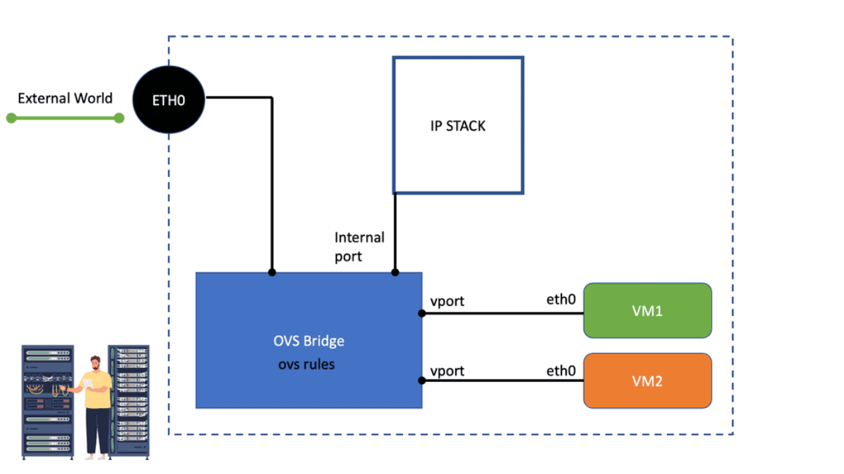
### Implementing Suricata in Your Network

Deploying Suricata IPS in your network involves several key steps. First, assess your network infrastructure to determine the optimal placement of the Suricata engine for maximum effectiveness. Typically, it is positioned at strategic points within the network to monitor traffic flow comprehensively. Next, configure Suricata with appropriate rulesets, either by utilizing available community rules or customizing them to address specific threats pertinent to your organization. Regular updates and fine-tuning of these rules are essential to maintain the system’s efficacy in detecting emerging threats.

The Role of DNS

Firstly, the basics. DNS (Domain Name System) is a host-distributed database that converts domain names to IP addresses. Most clients rely on DNS for communicating services such as Telnet, file transfer, and HTTP web browsing. It goes through a chain of events, usually only taking milliseconds for the client to receive a reply. Quick does not often mean secure. First, let us examine the DNS structure and DNS operations.

DNS Structure

The DNS Process

The clients send a DNS query to a local DNS server (LDNS), a Resolver. Then, the LDNS relays the request to a Root server with the required information to service the request. Root servers are a critical part of Internet architecture.

They are authoritative name servers that serve the DNS root zone by directly answering requests or returning a list of authoritative nameservers for the appropriate top-level domain (TLD). Unfortunately, this chain of events is the base of DNS-based DDoS attacks such as the DNS Recursion attack.

Guide on the DNS Process.

The DNS resolution process begins when a user enters a domain name in their browser. It involves several steps to translate the domain name into an IP address. In the example below, I have a CSR1000v configured as a DNS server and several name servers. I also have an external connector configured with NAT for external connectivity outside of Cisco Modelling Labs.

    • Notice the DNS Query and the DNS Response from the Packet Capture. Keep in mind this is UDP and, by default, insecure.

DNS process

Before you proceed, you may find the following posts useful for pre-information:

  1. DNS Security Solutions
  2. DNS Security Designs
  3. Cisco Umbrella CASB
  4. OpenShift SDN
  5. DDoS Attacks
  6. UDP Scan
  7. IPv6 Attacks

The Domain Namespace

So, we have domain names that index DNS’s distributed database. Each domain name is a path in a large inverted tree called the domain namespace. So, when you think about the tree’s hierarchical structure, it is similar to the design of the Unix filesystem.

The tree has a single root at the top. So, the Unix filesystem represents the root directory by a slash (/). So, we have DNS that calls and refers to it as “the root.” But it’s a similar structure that, too, has limits. The DNS’s tree can branch any number of ways at each intersection point or node. However, the depth of the tree is limited to 127 levels, which you are not likely to reach.

DNS and its use of UDP

DNS uses User Datagram Protocol (UDP) as the transport protocol. UDP is a lot faster than TCP due to its stateless operation. Stateless means no connection state is maintained between UDP peers. It has no connection information, just a query/response process.

**Size of unfragmented UDP packets

One problem with using UDP as the transport protocol is that the size of unfragmented UDP packets has limited the number of root server addresses to 13. To alleviate this problem, root server IP addressing is based on Anycast, permitting the number of root servers to be larger than 500. Anycast permits the same IP address to be advertised from multiple locations.

Understanding DNS Reflection Attack

The attacker identifies vulnerable DNS resolvers that can be abused to amplify the attack. These resolvers respond to DNS queries from any source without proper source IP address validation. By sending a small DNS request with the victim’s IP address as the source, the attacker tricks the resolver into sending a much larger response to the victim’s network. This amplification effect allows attackers to generate a significant traffic volume, overwhelming the victim’s infrastructure and rendering it inaccessible.

DNS Reflection Attacks can have severe consequences, both for individuals and organizations. Some of the critical impacts include:

    • Disruption of Online Services:

The attack can destroy websites, online services, and other critical infrastructure by flooding the victim’s network with massive amplified traffic. This can result in financial losses, reputational damage, and significant user inconvenience.

    • Collateral Damage:

In many cases, DNS Reflection Attacks can have collateral damage, affecting the intended target and other systems sharing the same network infrastructure. This can lead to a ripple effect, causing cascading failures and disrupting multiple online services simultaneously.

    • Loss of Confidentiality:

During a DNS Reflection Attack, attackers exploit chaos and confusion to gain unauthorized access to sensitive data. This can include stealing user credentials, financial information, or other valuable data, further exacerbating the damage caused by the attack.

To mitigate the risk of DNS Reflection Attacks, organizations should consider implementing the following measures:

    • Source IP Address Validation:

DNS resolvers should be configured to only respond to queries from authorized sources, preventing the use of open resolvers for amplification attacks.

    • Rate Limiting:

By implementing rate-limiting mechanisms, organizations can restrict the number of DNS responses sent to a particular IP address within a given time frame. This can help mitigate the impact of DNS Reflection Attacks.

    • Network Monitoring and Traffic Analysis:

Organizations should regularly monitor their network traffic to identify suspicious patterns or abnormal spikes in DNS traffic. Advanced traffic analysis tools can help detect and mitigate DNS Reflection Attacks in real-time.

    • DDoS Mitigation Services:

Engaging with reputable DDoS mitigation service providers can offer additional protection against DNS Reflection Attacks. These services employ sophisticated techniques to identify and filter malicious traffic, ensuring the availability and integrity of online services.

Exploiting DNS-Based DDoS Attacks

Attacking UDP

Mainly, denial of service (DoS) mechanisms disrupt activity and prevent upper-layer communication between hosts. Attacking UDP is often harder to detect than general DoS resource saturation attacks. Attacking UDP is not as complex as attacking TCP because UDP has no authentication and is connectionless.

This makes it easier to attack than some application protocols, which usually require authentication and integrity checks before accepting data. The potential threat against DNS is that it relies on UDP and is subject to UDP control plane threats. Launching an attack on a UDP session can be achieved without application awareness. 

1: **DNS query attack**

One DNS-based DDoS attack method is carrying out a DNS query attack. The attacker uses a tap client and sends a query to a remote DNS server to overload it with numerous clients, sending queries to the same DNS server. The capacity of a standard DNS server is about 150,000 queries. If the remote server does not have the capacity, it will drop and ignore the legitimate request and be unable to send responses. The DNS server cannot tell which query is good or bad. A query attack is a relatively simple attack. 

2: **DNS Recursion attack**

The recursive nature of DNS servers enables them to query one another to locate a DNS server with the correct IP address or to find an authoritative DNS server that holds the canonical mapping of the domain name to its IP address. The very nature of this operation opens up DNS to a DNS Recursion Attack. 

A DNS Recursion Attack is also known as a DNS cache poisoning attack. DNS attacks occur when a recursive DNS server requests an IP address from another; an attacker intercepts the request and gives a fake response, often the IP address for a malicious website.

3: **DNS reflection attack**

A more advanced form of DNS-based DDoS attacks is a technique called a DNS reflection attack. The attackers take advantage of the underlying vulnerability in the DNS protocol. The return address (source IP address in the query) is tricked into being someone else. This is known as DNS Spoofing or DNS cache poisoning.

The attackers send out a DNS request and set the IP address as their target for the source IP. The natural source gets overwhelmed with return traffic, and the source IP address is known to be spoofed.

The main reason for carrying out reflection attacks is an amplification. The advertisement of spoofed DNS name records enables the attacker to carry out many other attacks. As discussed, they can redirect flows to a destination of choice, which opens up other sophisticated attacks that facilitate eavesdropping, MiTM attacks, the injection of false data, and the distribution of Malware and Trojans.

DNS Reflection Attack
Diagram: DNS Reflection Attack.

DNS and unequal sizes

IPv4 & IPv6 Amplification Attacks

The nature of the DNS system is that it has unequal sizes. The query messages are tiny, and the response is typically double the query size. However, there are certain record types that you can ask for that are much more significant. Attackers may concentrate their attack using DNS security extension (DNSSEC) cryptographic or EDNS0 extensions. If you add DNSsec, it combines a lot of keys and makes the packet much larger.

These requests can increase packet size from around 40 bytes to above the maximum Ethernet packet size of 4000. They potentially require fragmentation, further targeting network resources. This is the essence of any IPv4 and IPv6 attack amplification: a small query with a significant response. Many load balancing products have built-in DoS protection, enabling you to set limits for packets per second on specific DNS queries.

Amplified with DNS Open Resolvers

The attack can be amplified even more with DNS Open Resolvers, enabling the least number of Bots with maximum damage. A Bot is a type of Malware that allows the attacker to control it. Generally, a security mechanism should be in place so resolvers only answer requests from a list of clients. These are called locked or secured DNS resolvers.

Unfortunately, many resolvers lack best-practice security mechanisms. Unfortunately, Open Resolvers amplify the amplification attack surface even further. DNS amplification is a variation of an old-school attack called an SMURF attack.

At a fundamental level, ensure you have an automated list to accept only known clients. Set up ingress filtering to ensure you don’t have an illegal address leaving your network. Ingress filtering prevents any spoofing-style attacks. This will weed it down and thin it out a bit.

Next, test your network and make sure you don’t have any Open Resolvers. NMAP (Network Mapper) is a tool with a script to test recursion. This will test whether your local DNS servers are open to recursion attacks.

Example DDOS Protection: GTM Load Balancer

At a more expensive level, F5 offers a product called DNS Express. It allows you to withstand DoS attacks by adding an F5 GTM Load Balancer to your DNS servers. DNS Express handles the request on behalf of the DNS server. It works from high-speed RAM and, on average, handles about 2 million requests per second.

This is about 12 times more than a regular DNS server, which should be enough to withstand a sophisticated DNS DoS attack. Later posts deal with mitigation techniques, including stateful firewalls and other devices.

Closing Points on DNS Reflection Attack

A DNS Reflection Attack is a type of Distributed Denial of Service (DDoS) attack that leverages the Domain Name System (DNS) to overwhelm a target with traffic. The attacker sends a small query to a DNS server, spoofing the IP address of the victim. The server, in turn, responds with a much larger packet, sending it to the victim’s address. By exploiting numerous DNS servers, an attacker can amplify the volume of data directed at the target, effectively crippling their services.

The mechanics of a DNS Reflection Attack are both clever and destructive. At its core, the attack relies on two primary components: spoofing and amplification. Here’s a step-by-step breakdown of the process:

1. **Spoofing**: The attacker sends DNS requests to multiple open DNS resolvers, using the victim’s IP address as the source address.

2. **Amplification**: These DNS requests are crafted to trigger large responses. A small request can generate a response that is several times larger, due to the nature of DNS queries and responses.

3. **Reflection**: The DNS servers send the amplified responses to the victim’s IP address, inundating their network with data and leading to service disruption.

The consequences of a successful DNS Reflection Attack can be severe, affecting not only the direct victim but also the broader network infrastructure. Some of the notable impacts include:

– **Service Downtime**: The primary goal of a DNS Reflection Attack is to render services unavailable. This can lead to significant financial losses and damage to reputation for businesses.

– **Network Congestion**: The flood of traffic can cause congestion on the network, affecting legitimate users and potentially leading to further delays and outages.

– **Collateral Damage**: Open DNS resolvers used in the attack can also face repercussions, as they become unwitting participants in the attack, consuming resources and bandwidth.

Protecting against DNS Reflection Attacks requires a multi-layered approach, combining best practices and technological solutions. Here are some effective strategies:

– **Implement Rate Limiting**: Configure DNS servers to limit the number of responses sent to a single IP address within a specific timeframe, reducing the potential for amplification.

– **Use DNSSEC**: DNS Security Extensions (DNSSEC) add a layer of authentication to DNS responses, making it more difficult for attackers to spoof source IP addresses.

– **Deploy Firewalls and Intrusion Detection Systems (IDS)**: These tools can help identify and filter out malicious traffic, preventing it from reaching the intended target.

– **Close Open Resolvers**: Ensure that DNS servers are not open to the public, limiting their use to authorized users only.


Summary: DNS Reflection attack

In the vast realm of the internet, a fascinating phenomenon known as DNS reflection exists. This intriguing occurrence has captured the curiosity of tech enthusiasts and cybersecurity experts alike. In this blog post, we embarked on a journey to unravel the mysteries of DNS reflection and shed light on its inner workings.

Understanding DNS

Before diving into the intricacies of DNS reflection, it is essential to grasp the basics of DNS (Domain Name System). DNS serves as the backbone of the internet, translating human-readable domain names into IP addresses that computers can understand. It acts as a directory, facilitating seamless communication between devices across the web.

The Concept of Reflection

Reflection, in the context of DNS, refers to the bouncing back of packets between different systems. It occurs when a DNS server receives a query and responds by sending a more significant response to an unintended target. This amplification effect can lead to potentially devastating consequences if exploited by malicious actors.

Amplification Attacks

One of the most significant threats associated with DNS reflection is the potential for amplification attacks. Cybercriminals can leverage this vulnerability to launch large-scale distributed denial of service (DDoS) attacks. By spoofing the source IP address and sending a small query to multiple DNS servers, they can provoke a deluge of amplified responses to the targeted victim, overwhelming their network infrastructure.

Mitigation Strategies

Given the potential havoc that DNS reflection can wreak, it is crucial to implement robust mitigation strategies. Network administrators and cybersecurity professionals can take several proactive steps to protect their networks. These include implementing source IP verification, deploying rate-limiting measures, and utilizing specialized DDoS protection services.

Conclusion

In conclusion, DNS reflection poses a significant challenge in cybersecurity. By understanding its intricacies and implementing appropriate mitigation strategies, we can fortify our networks against potential threats. As technology evolves, staying vigilant and proactive is paramount in safeguarding our digital ecosystems.
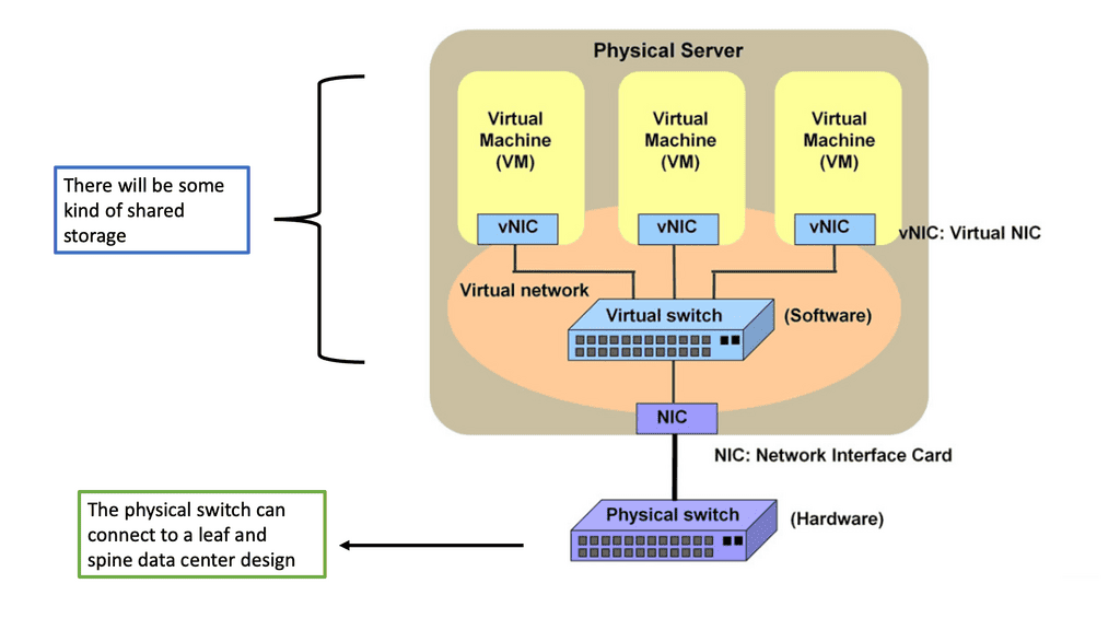
Layer-3 Data Center

Layer-3 Data Center

Layer 3 Data Center

In today's digital age, data centers play a crucial role in powering our interconnected world. Among various types of data centers, layer 3 data centers stand out for their advanced network capabilities and efficient routing techniques. In this blog post, we will embark on a journey to understand the intricacies and benefits of layer 3 data centers.

Layer 3 data centers are a vital component of modern networking infrastructure. They operate at the network layer of the OSI model, enabling the routing of data packets across different networks. This layer is responsible for logical addressing, packet forwarding, and network segmentation. Layer 3 data centers utilize specialized routers and switches to ensure fast and reliable data transmission.

One of the key advantages of layer 3 data centers is their ability to handle large-scale networks with ease. By utilizing IP routing protocols such as OSPF (Open Shortest Path First) and BGP (Border Gateway Protocol), layer 3 data centers can efficiently distribute network traffic, optimize paths, and adapt to changes in network topology. This scalability ensures that data can flow seamlessly between various devices and networks.

Layer 3 data centers provide enhanced security features compared to lower-layer data centers. With the implementation of access control lists (ACLs) and firewall rules, layer 3 data centers can enforce strict traffic filtering and prevent unauthorized access to sensitive information. Additionally, they offer advanced encryption and virtual private network (VPN) capabilities, ensuring secure communication between different networks and remote locations.

Layer 3 data centers offer flexibility and redundancy in network design. They support the creation of virtual LANs (VLANs), which enable the segmentation of networks for improved performance and security. Furthermore, layer 3 data centers can employ techniques like Equal-Cost Multi-Path (ECMP) routing, which distributes traffic across multiple paths, ensuring optimal resource utilization and fault tolerance.

Layer 3 data centers are the backbone of modern networking infrastructure, enabling efficient and secure data transmission across diverse networks. With their enhanced scalability, network security, flexibility, and redundancy, layer 3 data centers empower organizations to meet the demands of a rapidly evolving digital landscape. By harnessing the power of layer 3 data centers, businesses can pave the way for seamless connectivity and robust network performance.

Highlights: Layer 3 Data Center

The Role of Routing Logic

A Layer 3 Data Center is a type of data center that utilizes Layer 3 switching technology to provide network connectivity and traffic control. It is typically used in large-scale enterprise networks, providing reliable services and high performance.

Layer 3 Data Centers are differentiated from other data centers using Layer 3 switching. Layer 3 switching, also known as Layer 3 networking, is a switching technology that operates at the third layer of the Open Systems Interconnection (OSI) model, the network layer. This switching type manages network routing, addressing, and traffic control and supports various protocols.

Note: Routing Protocols

At its core, a Layer 3 data center is designed to operate at the network layer of the OSI (Open Systems Interconnection) model. This means it is responsible for routing data packets across different networks, rather than just switching them within a single network.

By leveraging routing protocols like BGP (Border Gateway Protocol) and OSPF (Open Shortest Path First), Layer 3 data centers facilitate more efficient and scalable networking solutions. This capability is crucial for businesses that require seamless connectivity across multiple sites and cloud environments.

Key Features and Architecture:

– Layer 3 data centers are designed with several key features that set them apart. Firstly, they employ advanced routing protocols and algorithms to efficiently handle network traffic. Additionally, they integrate firewall and security mechanisms to safeguard data and prevent unauthorized access. Layer 3 data centers also offer scalability, enabling seamless expansion and accommodating growing network demands.

– The utilization of Layer 3 data centers brings forth a myriad of advantages. Firstly, they enhance network performance by reducing latency and improving packet delivery. With their intelligent routing capabilities, they optimize the flow of data, resulting in faster and more reliable connections. Layer 3 data centers also enhance network security, providing robust protection against cyber threats and ensuring data integrity.

– Layer 3 data centers find extensive applications in various industries. They are particularly suitable for large enterprises with complex network architectures, as they provide the necessary scalability and flexibility. Moreover, Layer 3 data centers are instrumental in cloud computing environments, enabling efficient traffic management and interconnectivity between multiple cloud platforms.

Example Technology: BGP Route Reflection

Key Features and Functionalities:

1. Network Routing: Layer 3 data centers excel in routing data packets across networks, using advanced routing protocols such as OSPF (Open Shortest Path First) and BGP (Border Gateway Protocol). This enables efficient traffic management and optimal utilization of network resources.

2. IP Addressing: Layer 3 data centers assign and manage IP addresses, allowing devices within a network to communicate with each other and external networks. IP addressing helps identify and locate devices, ensuring reliable data transmission.

3. Interconnectivity: Layer 3 data centers provide seamless connectivity between different networks, whether they are local area networks (LANs), wide area networks (WANs), or the internet. This enables organizations to establish secure and reliable connections with their branches, partners, and customers.

4. Load Balancing: Layer 3 data centers distribute network traffic across multiple servers or network devices, ensuring that no single device becomes overwhelmed. This helps to maintain network performance, improve scalability, and prevent bottlenecks.

**Recap: Layer 3 Routing**

Layer 3 routing operates at the network layer of the OSI model and is responsible for forwarding data packets based on logical addressing. Routers are the primary devices that perform layer 3 routing. They use routing tables and algorithms to determine the best path for data to reach its intended destination. Layer 3 routing offers several advantages, including:

Scalability and Flexibility: Layer 3 routing allows for the creation of complex networks by connecting multiple subnets. It enables different network protocols and supports the interconnection of diverse networks, such as LANs and WANs.

Efficient Network Segmentation: Layer 3 routing facilitates network segmentation, which enhances security and performance. By dividing an extensive network into smaller subnets, layer 3 routing reduces broadcast traffic and isolates potential network issues.

router on a stick

**Recap: Layer 2 Switching**

Layer 2 switching operates at the data link layer of the OSI model, facilitating the forwarding of data packets based on Media Access Control (MAC) addresses. Unlike layer 3 switching, which relies on IP addresses, layer 2 switching enables devices within the same local network to communicate directly without routing through layer 3 devices such as routers. This direct communication results in faster and more efficient data transmission.

Broadcast Domain Segmentation: Layer 2 switching allows for segmenting broadcast domains, isolating network traffic within specific segments. This segmentation enhances network security by preventing broadcast storms and minimizing the impact of network failures.

VLANs and Layer 2 Switching

Virtual LANs (VLANs): VLANs enable the logical segmentation of a physical network into multiple virtual networks. Layer 2 switching supports VLANs, allowing for the creation of separate broadcast domains and providing enhanced network security and flexibility.

Inter-VLAN Routing: Layer 2 switches equipped with Layer 3 capabilities can perform inter-VLAN routing, enabling communication between VLANs. This functionality is crucial in more extensive networks where traffic segregation is necessary while allowing inter-VLAN communication.

Example Layer 3 Technology: Layer 3 Etherchannel

Layer 3 Etherchannel is a networking technology that bundles multiple physical links into one logical one. Unlike Layer 2 Etherchannel, which operates at the data link layer, Layer 3 Etherchannel operates at the network layer. It provides load balancing, redundancy, and enhanced bandwidth utilization for network devices.

Careful configuration is necessary to maximize Layer 3 Etherchannel. This section will explore critical considerations, including selecting the appropriate load-balancing algorithm, configuring IP addressing, and setting up routing protocols. We will also discuss the importance of consistent configuration across all participating devices to ensure seamless operation.

**Understanding Layer 3 Etherchannel Load Balancing**

Layer 3 Etherchannel is a method of bundling multiple physical links between switches into a single logical link. It enables the distribution of traffic across these links, thereby ensuring effective load balancing. By utilizing Layer 3 Etherchannel, network administrators can achieve improved bandwidth utilization, increased redundancy, and enhanced fault tolerance.

Configuring Layer 3 Etherchannel load balancing involves several important considerations. First, choosing an appropriate load-balancing algorithm that suits the specific network requirements is crucial. The available options, such as source-destination IP address or source-destination MAC address, offer different advantages and trade-offs. Additionally, attention should be given to the number of links bundled in the Etherchannel and the overall capacity and capabilities of the involved switches.

Network Connectivity Center

### Understanding Google Network Connectivity Center (NCC)

Google Network Connectivity Center is a unified platform that allows organizations to manage, monitor, and optimize their network connections across different environments. Whether connecting on-premises data centers, branch offices, or cloud resources, NCC provides a centralized hub for network management. It simplifies the complexities of networking, offering a cohesive solution that integrates seamlessly with Google Cloud.

### Key Features of NCC

1. **Centralized Management**: NCC offers a single pane of glass for managing network connections, making it easier to oversee and control networking across multiple environments. This centralized approach enhances visibility and simplifies troubleshooting.

2. **Interconnectivity**: With NCC, businesses can establish secure, high-performance connections between their on-premises infrastructure and Google Cloud. This interconnectivity ensures that data flows smoothly and securely, regardless of the location.

3. **Scalability and Flexibility**: NCC’s architecture supports scalability, allowing businesses to expand their network reach as they grow. Its flexible design ensures that it can adapt to changing needs, providing consistent performance even under varying workloads.

### Benefits of Using NCC

1. **Enhanced Performance**: By optimizing network paths and providing direct connections, NCC reduces latency and improves overall network performance. This is crucial for applications requiring real-time data processing and low-latency communication.

2. **Increased Security**: NCC employs robust security measures to protect data as it traverses the network. From encryption to secure access controls, NCC ensures that sensitive information remains safeguarded.

3. **Cost Efficiency**: By consolidating network management and optimizing resource usage, NCC can lead to significant cost savings. Organizations can reduce expenses associated with maintaining multiple network management tools and streamline their operational costs.

High-Performance Routers and Switches

Layer 3 Data Centers are typically characterized by their use of high-performance routers and switches. These routers and switches are designed to deliver robust performance, scalability, and high levels of security. In addition, by using Layer 3 switching, these data centers can provide reliable network services such as network access control, virtual LANs, and Quality of Service (QoS) management.

Understanding High Performance Routers

Routers are the digital traffic cops of the internet, directing data between devices and networks. High performance routers take this role to another level by offering faster speeds, increased bandwidth, and enhanced security features. These routers are equipped with advanced technologies like MU-MIMO and beamforming, which ensure that multiple devices can connect simultaneously without any loss in speed or quality. This is particularly vital in environments where numerous devices are constantly online, such as smart homes and large offices.

The Role of Switches in Connectivity

Switches, on the other hand, act as the backbone of local area networks (LANs), connecting multiple devices within a single network while managing data traffic efficiently. High performance switches are designed to handle large volumes of data with minimal latency, making them ideal for businesses and enterprises that rely on real-time data processing. They support greater network flexibility and scalability, allowing networks to expand and adapt to growing demands without compromising performance.

**Benefits of Layer 3 Data Centers**

1. Enhanced Performance: Layer 3 data centers optimize network performance by efficiently routing traffic, reducing latency, and ensuring faster data transmission. This results in improved application delivery, enhanced user experience, and increased productivity.

2. Scalability: Layer 3 data centers are designed to support network growth and expansion. Their ability to route data across multiple networks enables organizations to scale their operations seamlessly, accommodate increasing traffic, and add new devices without disrupting the network infrastructure.

3. High Security: Layer 3 data centers provide enhanced security measures, including firewall protection, access control policies, and encryption protocols. These measures safeguard sensitive data, protect against cyber threats, and ensure compliance with industry regulations.

4. Flexibility: Layer 3 data centers offer network architecture and design flexibility. They allow organizations to implement different network topologies based on their specific requirements, such as hub-and-spoke, full mesh, or partial mesh.

BGP-only data centers

BGP Data Center Design

Many cloud-native data center networks range from giant hyperscalers like Amazon, Google, and Microsoft to smaller organizations with anywhere from 20 to 50 switches. However, reliability and cost efficiency are common goals across them all.

Compared to purchasing a router, operational cost efficiency is much more complicated. Following the following design principles, cloud-native data center networks achieve reliable, cost-efficient networks in my experience dealing with a wide range of organizations. BGP fits the following design principles.

  • Simple, standard building blocks
  • Failures in the network should be reconsidered
  • Focus on simplicity with ruthlessness

BGP, a dynamic routing protocol, is crucial in interconnecting different autonomous systems (AS) online. Traditionally used in wide area networks (WANs), BGP is now entering data centers, offering unparalleled benefits. BGP enables efficient packet forwarding and optimal path selection by exchanging routing information between routers.

Traditionally, data centers have relied on multiple routing protocols, such as OSPF or EIGRP, alongside BGP to manage network traffic. However, as the scale and complexity of data centers have grown, so too have the challenges associated with managing disparate protocols. By consolidating around BGP, network administrators can streamline operations, reduce overhead, and enhance scalability.

The primary advantage of implementing BGP as the sole routing protocol is simplification. With BGP, data centers can achieve consistent policy control and a uniform routing strategy across the entire network. Additionally, BGP offers robust scalability, allowing data centers to handle a large number of routes efficiently. This section will outline these benefits in detail, providing examples of how BGP-only deployments can lead to improved network performance and reliability.

Example BGP Technology: BGP Only Data Center

## The Role of TCP Port 179

BGP operates over Transmission Control Protocol (TCP), specifically utilizing port 179. This choice ensures reliable delivery of routing information, as TCP guarantees data integrity and order. The use of TCP port 179 is significant because it establishes a stable and consistent communication channel between peers, allowing them to exchange routing tables and updates efficiently. This setup is crucial for maintaining the dynamic nature of the internet’s routing tables as networks grow and change.

## Types of BGP Peering: IBGP vs. EBGP

BGP peering can be categorized into two primary types: Internal BGP (IBGP) and External BGP (EBGP). IBGP occurs within a single autonomous system, facilitating the distribution of routing information internally. It ensures that routers within the same AS are aware of the best paths to reach various network destinations. On the other hand, EBGP is used between different autonomous systems, enabling the exchange of routing information across organizational boundaries. Understanding the differences between these two is essential for network engineers to optimize routing policies and ensure efficient data flow.

## Peering Policies and Agreements

The establishment of BGP peering requires careful consideration of peering policies and agreements. Network operators must decide on the terms of peering, which can include settlement-free peering, paid peering, or transit arrangements. These policies dictate how traffic is exchanged, how costs are shared, and how disputes are resolved. Crafting effective peering agreements is vital for maintaining good relationships between different network operators and ensuring stable connectivity.

BGP Key Considerations:

Enhanced Scalability: BGP’s ability to handle large-scale networks makes it an ideal choice for data centers experiencing exponential growth. With BGP, data centers can handle thousands of routes and efficiently distribute traffic across multiple paths.

Increased Resilience: Data centers require high availability and fault tolerance. BGP’s robustness and ability to detect network failures make it valuable. BGP minimizes downtime and enhances network resilience by quickly rerouting traffic to alternative paths.

Improved Traffic Engineering: BGP’s advanced features enable precise control over traffic flow within the data center. Network administrators can implement traffic engineering policies, load balancing, and prioritization, ensuring optimal resource utilization.

Technologies: BGP-only Data Centers

Nexus 9000 Series VRRP

Nexus 9000 Series VRRP is a high-performance routing protocol designed to provide redundancy and fault tolerance in network environments. It allows for the automatic failover of routers in case of a failure, ensuring seamless connectivity and minimizing downtime. By utilizing VRRP, businesses can achieve enhanced network availability and reliability.

The Nexus 9000 Series VRRP has many features that make it a compelling choice for network administrators. Firstly, it supports IPv4 and IPv6, ensuring compatibility with modern network architectures. Additionally, it offers load-balancing capabilities, distributing traffic efficiently across multiple routers. This not only improves overall network performance but also optimizes resource utilization. Furthermore, Nexus 9000 Series VRRP provides simplified management and configuration options, streamlining the deployment process and reducing administrative overhead.

Example: Prefer EBGP over iBGP

Understanding BGP Path Attributes

BGP path attributes are pieces of information associated with each BGP route. They carry valuable details such as the route’s origin, the path the route has taken, and various other characteristics. These attributes are crucial in determining the best path for routing packets.

Network engineers commonly encounter several BGP path attributes. Some notable ones include AS Path, Next Hop, Local Preference, and MED (Multi-Exit Discriminator). Each attribute serves a specific purpose and aids in the efficient functioning of BGP.

Implementing BGP in Data Centers

Before diving into the implementation details, it is essential to grasp the fundamentals of BGP. BGP is an exterior gateway protocol that enables the exchange of routing information between different autonomous systems (AS).

It leverages a path-vector algorithm to make routing decisions based on various attributes, including AS path, next-hop, and network policies. This dynamic nature of BGP makes it ideal for data centers that require dynamic and adaptable routing solutions.

Implementing BGP in data centers brings forth a myriad of advantages. Firstly, BGP facilitates load balancing and traffic engineering by intelligently distributing traffic across multiple paths, optimizing network utilization and reducing congestion.

Additionally, BGP offers enhanced fault tolerance and resiliency through its ability to quickly adapt to network changes and reroute traffic. Moreover, BGP’s support for policy-based routing allows data centers to enforce granular traffic control and prioritize certain types of traffic based on defined policies.

**Challenges and Considerations**

While BGP offers numerous benefits, its implementation in data centers also poses certain challenges. One of the key considerations is the complexity associated with configuring and managing BGP. Data center administrators need to have a thorough understanding of BGP principles and carefully design their BGP policies to ensure optimal performance.

Furthermore, the dynamic nature of BGP can lead to route convergence issues, which require proactive monitoring and troubleshooting. It is crucial to address these challenges through proper planning, documentation, and ongoing network monitoring.

To ensure a successful BGP implementation in data centers, adhering to best practices is essential. Firstly, it is recommended to design a robust and scalable network architecture that accounts for future growth and increased traffic demands.

Additionally, implementing route reflectors or BGP confederations can help mitigate the complexity associated with full mesh connectivity. Regularly reviewing and optimizing BGP configurations, as well as implementing route filters and prefix limits, are also crucial steps to maintain a stable and secure BGP environment.

Example: BGP Multipath

Understanding BGP Multipath

BGP Multipath, short for Border Gateway Protocol Multipath, enables the simultaneous installation of multiple paths at an equal cost for a given destination network. This allows for load sharing across these paths, distributing traffic and mitigating congestion. By harnessing this capability, network administrators can maximize their resources, enhance network performance, and better utilize network links.

Implementing BGP Multipath offers several advantages.

a) First, it enhances network resiliency and fault tolerance by providing redundancy. In case one path fails, traffic can seamlessly reroute through an alternative path, minimizing downtime and ensuring uninterrupted connectivity.

b) Second, BGP Multipath enables better bandwidth utilization, as traffic can be distributed evenly across multiple paths. This load-balancing mechanism optimizes network performance and reduces the risk of bottlenecks, resulting in a smoother and more efficient user experience.

**BGP Data Center Key Points**

Hardware and Software Considerations: Suitable hardware and software support are essential for implementing BGP in data centers. Data center switches and routers should be equipped with BGP capabilities, and the chosen software should provide robust BGP configuration options.

Designing BGP Topologies: Proper BGP topology design is crucial for optimizing network performance. Data center architects should consider factors such as route reflectors, peer groups, and the correct placement of BGP speakers to achieve efficient traffic distribution.

Configuring BGP Policies: BGP policies are vital in controlling route advertisements and influencing traffic flow. Administrators should carefully configure BGP policies to align with data center requirements, considering factors like path selection, filtering, and route manipulation.

BGP in the data center

Due to its versatility, BGP is notoriously complex. IPv4 and IPv6, as well as virtualization technologies like MPLS and VXLAN, are all supported by BGP peers. Therefore, BGP is known as a multiprotocol routing protocol. Complex routing policies can be applied because BGP exchanges routing information across administrative domains. As a result of these policies, BGP calculates the best path to reach destinations, announces routes, and specifies their attributes. BGP also supports Unequal-Cost Multipath (UCMP), though not all implementations do.

BGP in the data center

Example Technology: BGP Route Reflection

BGP route reflection is used in BGP networks to reduce the number of BGP peering sessions required when propagating routing information. Instead of forcing each BGP router to establish a full mesh of connections with every other router in the network, route reflection allows for a hierarchical structure where certain routers act as reflectors.

These reflectors receive routing updates from their clients and reflect them to other clients, effectively reducing the complexity and overhead of BGP peering.

Configuring BGP route reflection involves designating certain routers as route reflectors and configuring the appropriate BGP attributes. Route reflectors should be strategically placed within the network to ensure efficient distribution of routing information.

Determining route reflector clusters and client relationships is essential to establish the hierarchy effectively. Network administrators can optimize routing update flow by adequately configuring route reflectors and ensuring seamless communication between BGP speakers.

Example Technology: BGP Next hop tracking

Using BGP next-hop tracking, we can reduce BGP convergence time by monitoring changes in BGP next-hop addresses in the routing table. It is an event-based system because it detects changes in the routing table. When it detects a change, it schedules a next hop scan to adjust the next hop in the BGP table.

Understanding Port Channel on Nexus

Port Channel, also known as Link Aggregation, is a technique that allows multiple physical links to be combined into a single logical link. This aggregation enhances bandwidth capacity and redundancy by creating a virtual port channel interface. By effectively utilizing multiple links, the Cisco Nexus 9000 Port Channel delivers superior performance and fault tolerance.

Configuring a Cisco Nexus 9000 Port Channel is straightforward and requires a few essential steps. First, ensure that the physical interfaces participating in the Port Channel are correctly connected. Then, create a Port Channel interface and assign a unique channel-group number. Next, assign the physical interfaces to the Port Channel using the channel-group command. Finally, the Port Channel settings, such as the load balancing algorithm and interface mode, are configured.

Certain best practices should be followed to optimize the performance of the Cisco Nexus 9000 Port Channel. First, select the appropriate load-balancing algorithm based on your network requirements—options like source-destination IP hash or source-destination MAC hash offer effective load distribution. Second, ensure that the physical interfaces connected to the Port Channel have consistent configuration settings. A mismatch can lead to connectivity issues and reduced performance.

Key Data Center Technology: Understanding VPC

VPC enables the creation of a virtual link between two physical switches, allowing them to operate as a single logical entity. This eliminates the traditional challenges associated with Spanning Tree Protocol (STP) and enhances network resiliency and bandwidth utilization. The Cisco Nexus 9000 series switches provide robust support for VPC, making them an ideal choice for modern data centers.

The Cisco Nexus 9000 series switches provide comprehensive support for VPC deployment. The process involves establishing a peer link between the switches, configuring VPC domain parameters, and creating port channels. Additionally, VPC can be seamlessly integrated with advanced features such as Virtual Extensible LAN (VXLAN) and fabric automation, further enhancing network capabilities.

Understanding Unidirectional Links

Unidirectional links occur when data traffic can flow in one direction but not in the opposite direction. This can happen for various reasons, such as faulty cables, misconfigurations, or hardware failures. Identifying and resolving these unidirectional links is crucial to maintaining a healthy network environment.

UDLD is a Cisco proprietary protocol designed to detect and mitigate unidirectional links. It operates at the data link layer, exchanging heartbeat messages between neighboring devices. By comparing the received and expected heartbeat messages, UDLD can identify any discrepancies and take appropriate actions.

– Network Resiliency: UDLD helps identify unidirectional links promptly, allowing network administrators to proactively rectify the issues. This leads to improved network resiliency and reduced downtime.

– Data Integrity: Unidirectional links can result in data loss or corruption. With UDLD in place, potential data integrity issues can be identified and addressed, ensuring reliable data transmission.

– Simplified Troubleshooting: UDLD provides clear alerts and notifications when unidirectional links are detected, making troubleshooting faster and more efficient. This helps network administrators pinpoint the issue’s root cause without wasting time on unnecessary investigations.

The Role of EVPN

BGP, traditionally used for routing between autonomous systems on the internet, has found its way into data centers due to its scalability and flexibility. When combined with EVPN, BGP becomes a powerful tool for creating virtualized and highly efficient networks within data centers. EVPN extends BGP to support Ethernet-based services, allowing for seamless connectivity and advanced features.

The adoption of BGP and EVPN in data centers brings numerous advantages. Firstly, it provides efficient and scalable multipath forwarding, allowing for better utilization of network resources and load balancing.

Secondly, BGP and EVPN enable seamless mobility of virtual machines (VMs) within and across data centers, reducing downtime and enhancing flexibility. Additionally, these technologies offer simplified network management, increased security, and support for advanced network services.

Use Cases of BGP and EVPN in Data Centers

BGP and EVPN have found extensive use in modern data centers across various industries. One prominent use case is in the deployment of large-scale virtualized infrastructures. By leveraging BGP and EVPN, data center operators can create robust and flexible networks that can handle the demands of virtualized environments. Another use case is in the implementation of data center interconnects, allowing for seamless communication and workload mobility between geographically dispersed data centers.

As data centers continue to evolve, the role of BGP and EVPN is expected to grow even further. Future trends include the adoption of BGP and EVPN in hyperscale data centers, where scalability and efficiency are paramount. Moreover, the integration of BGP and EVPN with emerging technologies such as software-defined networking (SDN) and network function virtualization (NFV) holds great promise for the future of data center networking.

In network virtualization solutions such as EVPN, OSPF is sometimes used instead of BGP to build the underlay network. Many proprietary or open-source routing stacks outside of FRR do not support using a single BGP session with a neighbor to do both overlays and underlays.

Service providers traditionally configure underlay networks using IGPs and overlay networks using BGP. OSPF is often used by network administrators who are familiar with this model. Because most VXLAN networks use an IPv4 underlay exclusively, they use OSPFv2 rather than OSPFv3.

Example: Use Case Cumulus

The challenges of designing a proper layer-3 data center surface at the access layer. Dual-connected servers terminating on separate Top-of-Rack (ToR) switches cannot have more than one IP address—a limitation results in VLAN sprawl, unnecessary ToR inter-switch links, and uplink broadcast domain sharing.

Cumulus Networks devised a clever solution entailing the redistribution of Address Resolution Protocol (ARP), avoiding Multi-Chassis Link Aggregation (MLAG) designs, and allowing pure Layer-3 data center networks. Layer 2 was not built with security in mind. Introducing a Layer-3-only data center eliminates any Layer 2 security problems.
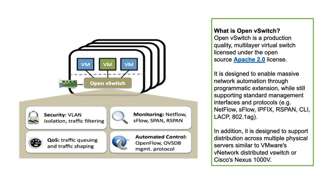
Layer 3 Data Center Performance

Understanding TCP Congestion Control

TCP Congestion Control is a crucial aspect of TCP performance parameters. It regulates the amount of data that can be sent before receiving acknowledgments. By adjusting the congestion window size and the slow-start threshold, TCP dynamically adapts to the network conditions, preventing congestion and ensuring smooth data transmission.

– Window Size and Throughput: The TCP window size determines the amount of unacknowledged data sent before receiving an acknowledgment. A larger window size allows for increased throughput, as more data can be transmitted without waiting for acknowledgments. However, a balance must be struck to avoid overwhelming the network and inducing packet loss.

– Maximum Segment Size (MSS): The Maximum Segment Size (MSS) refers to the most significant amount of data that can be transmitted in a single TCP segment. It is an important parameter that affects TCP performance. By optimizing the MSS, we can minimize packet fragmentation and maximize network efficiency.

– Timeouts and Retransmission: Timeouts and retransmission mechanisms are crucial in TCP performance. When a packet is not acknowledged within a certain time limit, TCP retransmits the packet. Properly tuning the timeout value is essential for maintaining a balance between responsiveness and avoiding unnecessary retransmissions.

What is TCP MSS?

TCP MSS, or Maximum Segment Size, refers to the largest amount of data that can be sent in a single TCP segment. It plays a vital role in determining the efficiency and reliability of data transmission across networks. Understanding how TCP MSS is calculated and utilized is essential for network administrators and engineers.

The proper configuration of TCP MSS can significantly impact network performance. By adjusting the MSS value, data transfer can be optimized, and potential issues such as packet fragmentation and reassembly can be mitigated. This section will explore the importance of TCP MSS in ensuring smooth and efficient data transmission.

Various factors, such as network technologies, link types, and devices involved, can influence the determination of TCP MSS. Considering these factors when configuring TCP MSS is crucial to prevent performance degradation and ensure compatibility across different network environments. This section will discuss the key aspects that need to be considered.

Adhering to best practices for TCP MSS configuration is essential to maximizing network performance. This section will provide practical tips and guidelines for network administrators to optimize TCP MSS settings, including consideration of MTU (Maximum Transmission Unit) and PMTUD (Path MTU Discovery) mechanisms.

Data Center Overlay Technologies

Example: VXLAN Flood and Learn

The Flood and Learn Mechanism

The Flood and Learn mechanism within VXLAN allows for dynamic learning of MAC addresses in a VXLAN segment. The destination MAC address is unknown when a packet arrives at a VXLAN Tunnel Endpoint (VTEP). The packet is then flooded across all VTEPs within the VXLAN segment, and the receiving VTEPs learn the MAC address associations. As a result, subsequent packets destined for the same MAC address can be forwarded directly, optimizing network efficiency.
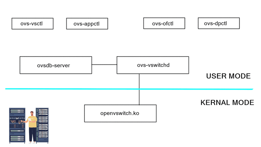

Multicast plays a crucial role in VXLAN Flood and Learn. Using multicast groups, VXLAN-enabled switches can efficiently distribute broadcast, unknown unicast, and multicast (BUM) traffic across the network. Multicast allows for optimized traffic replication, reducing unnecessary network congestion and improving overall performance.

Implementing VXLAN Flood and Learn with Multicast requires careful planning and configuration. Key aspects to consider include proper multicast group selection, network segmentation, VTEP configuration, and integration with existing network infrastructure. A well-designed implementation ensures optimal performance and scalability.

VXLAN Flood and Learn with Multicast finds its application in various scenarios. Data centers with virtualized environments benefit from the efficient forwarding of traffic, reducing network load and improving overall performance. VXLAN Flood and Learn with Multicast is instrumental in environments where workload mobility and scalability are critical, such as cloud service providers and multi-tenant architectures.

BGP Add Path

Understanding BGP Add Path

At its core, BGP Add Path enhances the traditional BGP route selection process by allowing the advertisement of multiple paths for a particular destination prefix. This means that instead of selecting a single best forward path, BGP routers can now keep numerous paths in their routing tables, each with its attributes. This opens up a new realm of possibilities for network engineers to optimize their networks and improve overall performance.

The BGP Add Path feature offers several benefits. First, it enhances network resilience by providing redundant paths for traffic to reach its destination. In case of link failures or congested paths, alternative routes can be quickly utilized, ensuring minimal disruption to network services. Additionally, it allows for improved load balancing across multiple paths, maximizing bandwidth utilization and optimizing network resources.

Traffic Engineering & Policy Routing

Furthermore, BGP Add Path is precious when traffic engineering and policy-based routing are crucial. Network administrators can now manipulate the selection of paths based on specific criteria such as latency, cost, or path preference. This level of granular control empowers them to fine-tune their networks according to their unique requirements.

Network devices must support the feature to leverage the power of BGP Add Path. Fortunately, major networking vendors have embraced this enhancement and incorporated it into their products. Implementation typically involves enabling the feature on BGP routers and configuring the desired behavior for path selection and advertisement. Network operators must also ensure their network infrastructure can handle the additional memory requirements of storing multiple paths.

You may find the following helpful post for pre-information:

  1. Spine Leaf Architecture
  2. Optimal Layer 3 Forwarding
  3. Virtual Switch 
  4. SDN Data Center
  5. Data Center Topologies
  6. LISP Hybrid Cloud Implementation
  7. IPv6 Attacks
  8. Overlay Virtual Networks
  9. Technology Insight For Microsegmentation

Layer 3 Data Center

Understanding VPC Networking

VPC networking provides a virtual network environment for your Google Cloud resources. It allows you to logically isolate your resources, control network traffic, and establish connectivity with on-premises networks or other cloud providers. With VPC networking, you have complete control over IP addressing, subnets, firewall rules, and routing.

Google Cloud’s VPC networking offers a range of powerful features that enhance network management and security. These include custom IP ranges, multiple subnets, network peering, and VPN connectivity. By leveraging these features, you can design a flexible and secure network architecture that meets your specific requirements.

To make the most out of VPC networking in Google Cloud, it is essential to follow best practices. Start by carefully planning your IP address ranges and subnet design to avoid potential conflicts or overlaps. Implement granular firewall rules to control inbound and outbound traffic effectively. Utilize network peering to establish efficient communication between VPC networks. Regularly monitor and optimize your network for performance and cost efficiency.

Understanding VPC Peering

VPC Peering is a technology that allows the connection of Virtual Private Clouds (VPCs) within the same cloud provider or across multiple cloud providers. It enables secure and private communication between VPCs, facilitating data exchange and resources. Whether using Google Cloud or any other cloud platform, VPC Peering is a powerful tool that enhances network connectivity.

VPC Peering offers organizations a plethora of benefits. First, it simplifies network architecture by eliminating the need for complex VPN configurations or public IP addresses. Second, it provides low-latency and high-bandwidth connections, ensuring efficient data transfer between VPCs. Third, it enables organizations to create a unified network infrastructure, facilitating easier management and resource sharing.

**Concepts of traditional three-tier design**

The classic data center uses a three-tier architecture, segmenting servers into pods. The architecture consists of core routers, aggregation routers, and access switches to which the endpoints are connected. Spanning Tree Protocol (STP) is used between the aggregation routers and access switches to build a loop-free topology for the Layer 2 part of the network. STP is simple and a plug-and-play technology requiring little configuration.

VLANs are extended within each pod, and servers can move freely within a pod without the need to change IP addresses and default gateway configurations. However, the downside of Spanning Tree Protocol is that it cannot use parallel forwarding paths and permanently blocks redundant paths in a VLAN.

Spanning tree VXLAN
Diagram: Loop prevention. Source is Cisco

A key point: Are we using the “right” layer 2 protocol?

Layer 1 is the easy layer. It defines an encoding scheme needed to pass ones and zeros between devices. Things get more interesting at Layer 2, where adjacent devices exchange frames (layer 2 packets) for reachability. Layer-2 or MAC addresses are commonly used at Layer 2 but are not always needed. Their need arises when more than two devices are attached to the same physical network.

Imagine a device receiving a stream of bits. Does it matter if Ethernet, native IP, or CLNS/CLNP comes in the “second” layer? First, we should ask ourselves whether we use the “right” layer 2 protocol.

Concept of VXLAN

To overcome the issues of Spanning Tree, we have VXLAN. VXLAN is an encapsulation protocol used to create virtual networks over physical networks. Cisco and VMware developed it, and it was first published in 2011. VXLAN provides a layer 2 overlay on a layer 3 network, allowing traffic separation between different virtualized networks.

This is useful for cloud-based applications and virtualized networks in corporate environments. VXLAN works by encapsulating an Ethernet frame within an IP packet and then tunneling it across the network. This allows more extensive virtual networks to be created over the same physical infrastructure.

Additionally, VXLAN provides a more efficient routing method, eliminating the need to use multiple VLANs. It also separates traffic between multiple virtualized networks, providing greater security and control. VXLAN also supports multicast traffic, allowing faster data broadcasts to various users. VXLAN is an important virtualization and cloud computing tool, providing a secure, efficient, and scalable means of creating virtual networks.

Multipath Route Forwarding

Many networks implement VLANs to support random IP address assignment and IP mobility. The switches perform layer-2 forwarding even though they might be capable of layer-3 IP forwarding. For example, they forward packets based on MAC addresses within a subnet, yet a layer-3 switch does not need Layer 2 information to route IPv4 or IPv6 packets.

Cumulus has gone one step further and made it possible to configure every server-to-ToR interface as a Layer 3 interface. Their design permits multipath default route forwarding, removing the need for ToR interconnects and common broadcast domain sharing of uplinks.  

Layer-3 Data Center: Bonding Vs. ECMP

A typical server environment consists of a single server with two uplinks. For device and link redundancy, uplinks are bonded into a port channel and terminated on different ToR switches, forming an MLAG. As this is an MLAG design, the ToR switches need an inter-switch link. Therefore, you cannot bond server NICs to two separate ToR switches without creating an MLAG.

Layer-3 Data Center
Diagram: Layer-3 Data Center.

If you don’t want to use an MLAG, other Linux modes are available on hosts, such as “active | passive” and “active | passive on receive.” A 3rd mode is available but consists of a trick using other ARP replies for the neighbors. This forces both MAC addresses into your neighbors’ ARP cache, allowing both interfaces to receive. The “active | passive” model is popular as it offers predictable packet forwarding and easier troubleshooting.

The “active | passive on receive” mode receives on one link but transmits on both. Usually, you can only receive on one interface, as that is in your neighbors’ ARP cache. To prevent MAC address flapping at the ToR switch, separate MAC addresses are transmitted. A switch receiving the same MAC address over two different interfaces will generate a MAC Address Flapping error.

We have a common problem in each bonding example: we can’t associate one IP address with two MAC addresses. These solutions also require ToR inter-switch linksThe only way to get around this is to implement a pure layer-3 Equal-cost multipath routing (ECMP) solution between the host and ToR. 

Pure layer-3 solution complexities

Firstly, we cannot have one IP address with two MAC addresses. To overcome this, we implement additional Linux features. First, Linux has the capability for an unnumbered interface, permitting the assignment of the same IP address to both interfaces, one IP address for two physical NICs. Next, we assign a /32 Anycast IP address to the host via a loopback address. 

Secondly, the end hosts must send to a next-hop, not a shared subnet. Linux allows you to specify an attribute to the received default route, called “on-link.” This attribute tells end-hosts, “I might not be on a directly connected subnet to the next hop, but trust me, the next hop is on the other side of this link.” It forces hosts to send ARP requests regardless of common subnet assignment.

These techniques enable the assignment of the same IP address to both interfaces and permit forwarding a default route out of both interfaces. Each interface is on its broadcast domain. Subnets can span two ToRs without requiring bonding or an inter-switch link.

**Standard ARP processing still works**

Although the Layer 3 ToR switch doesn’t need Layer 2 information to route IP packets, the Linux end-host believes it has to deal with the traditional L2/L3 forwarding environment. As a result, the Layer 3 switch continues to reply to incoming ARP requests. The host will ARP for the ToR Anycast gateway (even though it’s not on the same subnet), and the ToR will respond with its MAC address. The host ARP table will only have one ARP entry because the default route points to a next-hop, not an interface.

Return traffic differs slightly depending on what the ToR advertises to the network. There are two modes: first, if the ToR advertises a /24 to the rest of the network, everything works fine until the server-to-ToR link fails. Then, it becomes a layer-2 problem; as you said, you could reach the subnet. This results in return traffic traversing an inter-switch ToR link to get back to the server.

But this goes against our previous design requirement to remove any ToR inter-switch links. Essentially, you need to opt for the second mode and advertise a /32 for each host back into the network.

Take the information learned in ARP, consider it a host routing protocol, and redistribute it into the data center protocol, i.e., redistribute ARP. The ARP table gets you the list of neighbors, and the redistribution pushes those entries into the routed fabric as /32 host routes. This allows you to redistribute only what /32 are active and present in ARP tables. It should be noted that this is not a default mode and is currently an experimental feature.

A Final Note: Layer 3 Data Centers

Layer 3 data centers offer several advantages over their Layer 2 counterparts. One of the main benefits is their ability to handle a larger volume of data traffic without compromising speed or performance. By utilizing advanced routing protocols, Layer 3 data centers can efficiently manage data packets, reducing latency and improving overall network performance. Additionally, these data centers provide enhanced security features, as they are capable of implementing more sophisticated access control measures and firewall protections.

When considering a transition to a Layer 3 data center, there are several factors to take into account. First, it’s essential to evaluate the existing network infrastructure and determine if it can support the advanced capabilities of a Layer 3 environment. Organizations should also consider the potential costs associated with upgrading hardware and software, as well as the training required for IT staff to effectively manage the new system. Additionally, businesses should assess their specific needs for scalability and flexibility to ensure that a Layer 3 data center aligns with their long-term strategic goals.

As technology continues to advance, the role of Layer 3 data centers is expected to grow even more significant. With the rise of cloud computing, Internet of Things (IoT) devices, and edge computing, the demand for efficient and reliable network routing will only increase. Layer 3 data centers are well-positioned to meet these demands, offering the necessary infrastructure to support the growing complexity of modern networks. Furthermore, advancements in artificial intelligence and machine learning are likely to enhance the capabilities of Layer 3 data centers, enabling even more sophisticated data management solutions.

Summary: Layer 3 Data Center

In the ever-evolving world of technology, layer 3 data centers are pivotal in revolutionizing how networks are designed, managed, and scaled. By providing advanced routing capabilities and enhanced network performance, layer 3 data centers offer a robust infrastructure solution for businesses of all sizes. In this blog post, we explored the key features and benefits of layer 3 data centers, their impact on network architecture, and why they are becoming an indispensable component of modern IT infrastructure.

Understanding Layer 3 Data Centers

Layer 3 data centers, also known as network layer or routing layer data centers, are built upon the foundation of layer 3 switches and routers. Unlike layer 2 data centers that primarily focus on local area network (LAN) connectivity, layer 3 data centers introduce the concept of IP routing. This enables them to handle complex networking tasks, such as interconnecting multiple networks, implementing Quality of Service (QoS), and optimizing traffic flow.

Benefits of Layer 3 Data Centers

Enhanced Network Scalability: Layer 3 data centers offer superior scalability by leveraging dynamic routing protocols such as OSPF (Open Shortest Path First) and BGP (Border Gateway Protocol). These protocols enable efficient distribution of network routes, load balancing, and automatic failover, ensuring seamless network expansion and improved fault tolerance.

Improved Network Performance: With layer 3 data centers, network traffic is intelligently routed based on IP addresses, allowing faster and more efficient data transmission. By leveraging advanced routing algorithms, layer 3 data centers optimize network paths, reduce latency, and minimize packet loss, enhancing user experience and increased productivity.

Enhanced Security and Segmentation:Layer 3 data centers provide enhanced security features by implementing access control lists (ACLs) and firewall policies at the network layer. This enables strict traffic filtering, network segmentation, and isolation of different user groups or departments, ensuring data confidentiality and minimizing the risk of unauthorized access.

Impact on Network Architecture

The adoption of layer 3 data centers brings significant changes to network architecture. Traditional layer 2 networks are typically flat and require extensive configuration and maintenance. Layer 3 data centers, on the other hand, introduce hierarchical network designs, allowing for better scalability, easier troubleshooting, and improved network segmentation. By implementing layer 3 data centers, businesses can embrace a more flexible and agile network infrastructure that adapts to their evolving needs.

Conclusion:

Layer 3 data centers have undoubtedly transformed the networking landscape, offering unprecedented scalability, performance, and security. As businesses continue to rely on digital communication and data-driven processes, the need for robust and efficient network infrastructure becomes paramount. Layer 3 data centers provide the foundation for building resilient and future-proof networks, empowering businesses to thrive in the era of digital transformation.

Openflow protocol

OpenFlow Protocol

OpenFlow Protocol

The world of networking has witnessed remarkable advancements, and one of the key contributors to this progress is the OpenFlow protocol. In this blog post, we will dive into the depths of OpenFlow, exploring its principles, benefits, and impact on the networking landscape.

OpenFlow, at its core, is a communication protocol that enables the separation of network control and forwarding plane. By doing so, it empowers network administrators with a centralized control plane and facilitates programmable network management. This flexibility opens up a realm of possibilities for network optimization, innovation, and enhanced performance.

To grasp the essence of OpenFlow, it's essential to familiarize ourselves with its key principles. Firstly, OpenFlow operates on a flow-based model, treating packets as individual entities rather than traditional IP and MAC addresses. Secondly, it enables the dynamic modification of network behavior through a centralized controller, providing unprecedented control and adaptability. Lastly, OpenFlow fosters interoperability by ensuring compatibility across various networking devices from different vendors.

The adoption of OpenFlow brings forth a plethora of benefits. Firstly, it allows network administrators to exert fine-grained control over traffic flows, enabling them to optimize network performance and reduce latency. Secondly, OpenFlow facilitates network virtualization, empowering organizations to create isolated virtual networks without the need for physical infrastructure. Additionally, OpenFlow promotes innovation and fosters rapid experimentation by providing an open platform for application developers to create and deploy new network services.

OpenFlow and SDN are often mentioned in the same breath, as they go hand in hand. SDN is a paradigm that leverages OpenFlow to enable programmability, flexibility, and automation in network management. By decoupling the control and data planes, SDN architectures simplify network management, facilitate network orchestration, and enable the creation of dynamic, agile networks.

The OpenFlow protocol has revolutionized the networking landscape, empowering organizations with unprecedented control, flexibility, and performance optimization. As we sail into the future, OpenFlow will continue to be a key enabler of innovation, driving the evolution of networking technologies and shaping the digital world we inhabit.

Highlights: OpenFlow Protocol

Understanding OpenFlow Protocol

– The OpenFlow protocol is a communication standard allowing centralized control of network switches and routers. It separates the control plane from the data plane, enabling network administrators to have a holistic view of the network and make dynamic changes. Using a software-defined approach, OpenFlow opens up a realm of network management and optimization possibilities.

– OpenFlow boasts several essential features that make it a powerful tool in network management. These include flow-based forwarding, fine-grained control, and network programmability. Flow-based forwarding allows for traffic routing based on specific criteria, such as source or destination IP addresses.

– Fine-grained control enables administrators to set detailed rules and policies, ensuring optimal network performance. Network programmability allows for the customization and automation of network configurations, simplifying complex tasks.

Key Point: Flow-Based Forwarding

## Understanding the Basics of Flow-Based Forwarding

Flow-based forwarding is a method of routing network traffic based on predefined flows, which are essentially sequences of packets sharing the same attributes. Unlike traditional packet-based forwarding, which handles each packet independently, flow-based systems recognize and process flows as a single entity. This unified approach allows for more cohesive and efficient traffic management, as it can prioritize, route, and control data flows based on real-time requirements and policies.

## The Role of OpenFlow in Flow-Based Forwarding

OpenFlow is a pivotal protocol that enables flow-based forwarding by providing a standardized interface for programming network switches. It allows network administrators to define flows and enforce policies directly on the hardware, effectively separating the data plane from the control plane.

This separation empowers networks to be more adaptive and programmable, offering unprecedented levels of control over traffic behavior. OpenFlow’s ability to dynamically adjust to network conditions makes it an invaluable tool for implementing flow-based strategies across various applications.

**Key OpenFlow Benefits**

1: The adoption of the OpenFlow protocol brings numerous benefits to network environments. Firstly, it enhances network visibility and monitoring, enabling administrators to promptly identify and address potential bottlenecks or security threats.

2: Secondly, OpenFlow facilitates network flexibility and scalability, as changes can be easily implemented through centralized control. Moreover, the protocol promotes innovation by allowing new applications and services that leverage its programmability.

3: OpenFlow has significantly impacted network architecture, prompting a shift towards software-defined networking (SDN). SDN architectures provide a more agile and adaptable network infrastructure, enabling organizations to respond quickly to changing business requirements.

4: With OpenFlow as the backbone, SDN allows for the abstraction of network functions, making networks more programmable, scalable, and cost-effective.

**Key OpenFlow Features**

1. Centralized Control: OpenFlow Protocol provides a centralized control mechanism by decoupling the control plane from the devices. This allows network administrators to manage and configure network resources dynamically, making adapting to changing network demands easier.

2. Programmability: OpenFlow Protocol enables network administrators to program the behavior of network devices according to specific requirements. This programmability allows for greater flexibility and customization, making implementing new network policies and services easier.

3. Network Virtualization: OpenFlow Protocol supports virtualization, allowing multiple virtual networks to coexist on a single physical infrastructure. This capability enhances resource utilization and enables the creation of isolated network environments, enhancing security and scalability.

4. Traffic Engineering: With OpenFlow Protocol, network administrators have fine-grained control over traffic flows. This enables efficient load balancing, prioritization, and congestion management, ensuring optimal performance and resource utilization.

5. Software-Defined Networking (SDN): OpenFlow is a foundational element of Software-Defined Networking (SDN) architectures. SDN leverages the power of OpenFlow to decouple network control from hardware, enabling dynamic network management, automation, and scalability.

6. Traffic Engineering and Quality of Service (QoS): OpenFlow’s fine-grained control over network traffic enables advanced traffic engineering techniques. Network administrators can then prioritize specific types of traffic, allocate bandwidth efficiently, and ensure optimal Quality of Service (QoS) for critical applications.

**OpenFlow Use Cases**

1. Software-Defined Networking (SDN): OpenFlow Protocol is a key component of SDN, a network architecture separating the control and data planes. SDN leverages OpenFlow Protocol to provide a more flexible, programmable, and scalable network infrastructure.

2. Data Center Networking: OpenFlow Protocol offers significant advantages in data center environments, where dynamic workload placement and resource allocation are crucial. Using OpenFlow-enabled switches and controllers, data center operators can achieve greater agility, scalability, and efficiency.

3. Campus and Enterprise Networks: OpenFlow Protocol can simplify network management in large campus and enterprise environments. It allows network administrators to centrally manage and control network policies, improving network security, traffic engineering, and troubleshooting capabilities.

SDN: A History Guide

Martin Casado, a general partner at Andreessen Horowitz, would handle all the changes in the network industry. Previously, Casado worked for VMware as a fellow, senior vice president, and general manager. In addition to his direct contributions (like OpenFlow and Nicira), he has opened large network incumbents to the need to change network operations, agility, and manageability.

The Software-Defined Networking movement began with OpenFlow, whether for good or bad. During his Ph.D. at Stanford University, Casado worked on OpenFlow under Nick McKeown. Decoupling a network device’s control and data planes from the OpenFlow protocol is possible. A network device’s control plane consists of its brain, while its data plane consists of hardware that forwards packets or application-specific integrated circuits (ASICs).

Alternatively, OpenFlow can be run in a hybrid mode. It can be deployed on a specific port, virtual local area network (VLAN), or a regular packet-forwarding pipeline. Since there is no match in the OpenFlow table, packet forwarding is equivalent to policy-based routing (PBR).

SDN and OpenFlow

OpenFlow provides granularity in determining forwarding paths (matching fields in packets) because its tables support more than destination addresses. PBR provides granularity by considering the source address when selecting the next routing hop.

In a similar way to OpenFlow, it allows network administrators to forward traffic based on non-traditional attributes, such as packet source addresses. Despite taking quite some time for network vendors to offer comparable performance for PBR-forwarded traffic, the final result was still very vendor-specific.

OpenFlow allowed us to make traffic-forwarding decisions at the same granularity as before but without vendor bias. Thus, network infrastructure capabilities could be enhanced without waiting for the following hardware version.

Example Technology: Policy-Based Routing

**The Mechanics of Policy-Based Routing**

At its core, policy-based routing enables network operators to define custom routes based on a variety of criteria such as source IP address, application type, or even specific user requirements. This flexibility is particularly valuable in scenarios where network administrators need to manage traffic efficiently across multiple paths. By creating and applying access control lists (ACLs), administrators can dictate how and where traffic should flow, optimizing network performance and ensuring compliance with organizational policies.

**Benefits of Implementing PBR**

One of the primary advantages of policy-based routing is its ability to enhance the quality of service (QoS) across a network. By prioritizing certain types of traffic—such as VoIP or video conferencing—PBR can reduce latency and improve overall communication quality. Additionally, PBR can aid in load balancing by distributing traffic evenly across available links, preventing bottlenecks and ensuring that no single path becomes overwhelmed.

**Challenges and Considerations**

While the benefits of PBR are substantial, implementing it is not without challenges. Network administrators must carefully design and test their routing policies to avoid unintended consequences, such as routing loops or security vulnerabilities. Furthermore, the complexity of managing numerous policies can increase administrative overhead. Therefore, it’s crucial for organizations to invest in training and tools that simplify the management of PBR configurations.


Real-World Applications of OpenFlow

So, what is OpenFlow? OpenFlow is an open-source communications protocol that enables remote control of network devices from a centralized controller. It is most commonly used in software-defined networking (SDN) architectures, allowing networks to be configured and managed from a single point. OpenFlow enables network administrators to programmatically control traffic flow across their networks, allowing them to respond quickly to changing traffic patterns and optimize network performance.

**The Creation of Virtual Networks**

OpenFlow will also help it create virtual networks on top of existing physical networks, allowing for more efficient and flexible network management. As a result, OpenFlow is an essential tool for building and managing modern, agile networks that can quickly and easily adapt to changing network conditions. The following post discusses OpenFlow, the operations of the OpenFlow protocol, and the OpenFlow hardware components you can use to build an OpenFlow network.

What is OpenFlow

You may find the following helpful post for pre-information:

  1. SDN Adoption Report
  2. Network Traffic Engineering
  3. BGP SDN
  4. NFV Use Cases
  5. Virtual Switch 
  6. HP SDN Controller

OpenFlow Protocol

OpenFlow history

OpenFlow started in the labs as an academic experiment. They wanted to test concepts about new protocols and forwarding mechanisms on real hardware but failed with current architectures. The challenges of changing forwarding entries in physical switches limited the project to emulations. Emulations are a type of simulation and can’t mimic an entire production network.

The requirement to test on actual hardware (not emulations) leads to separating device planes (control, data, and management plane) and introducing the OpenFlow protocol and new OpenFlow hardware components.

Highlighting SDN

Standard network technologies, consisting of switches, routers, and firewalls, have existed since the inception of networking. Data at each layer is called different things, and forwarding has stayed the same since inception. Frames and packets have been forwarded and routed using a similar approach, resulting in limited efficiency and a high maintenance cost.

Consequently, there was a need to evolve the techniques and improve network operations, which led to the inception of SDN. SDN, often considered a revolutionary new idea in networking, pledges to dramatically simplify network control and management and enable innovation through network programmability.

software defined networking
Diagram: Software Defined Networking (SDN). Source is Opennetworking
  • A key point: The OpenFlow Protocol versions

OpenFlow has gone through several versions, namely versions 1.0 to 1.4. OpenFlow 1.0 was the initial version of the Open Network Foundation (ONF). Most vendors initially implemented version 1.0, which has many restrictions and scalability concerns. Version 1.0 was limited and proved the ONF rushed to the market without having a complete product.

Not many vendors implemented versions 1.1 or 1.2 and waited for version 1.3, allowing per-flow meter and Provider Backbone Bridging (PBB) support. Everyone thinks OpenFlow is “open,” but it is controlled by a closed group of around 150 member organizations, forming the ONF. The ONF specifies all the OpenFlow standards, and work is hidden until published as a standard.

OpenFlow Protocol: Separation of Planes

An OpenFlow network has several hardware components that enable three independent pieces: the data plane, control plane, and management plane.

A: – The data plane

The data plane switches Protocol Data Units (PDU) from incoming ports to destination ports. It uses a forwarding table. For example, a Layer 2 forwarding table could list MAC addresses and outgoing ports. A Layer 3 forwarding table contains IP prefixes with next hops and outgoing ports. The data plane is not responsible for creating the controls necessary to forward. Instead, someone else has the job of “filling in” the data plane, which is the control plane’s function.

B: – The control plane

The control plane is responsible for giving the data plane the required information to enable it to forward. It is considered the “intelligence” of the network as it makes the decisions about PDU forwarding. Control plane protocols are not limited to routing protocols; they’re more than just BGP and OSPF. Every single protocol that runs between adjacent devices is usually a control plane. Examples include line card protocols such as BFD, STP, and LACP.

These protocols do not directly interface with the forwarding table; for example, BFD detects failures but doesn’t remove anything from the forwarding table. Instead, it informs other higher-level control plane protocols of the problem and leaves them to change the forwarding behavior.

C: – The management plane

On the other hand, protocols like OSPF and ISIS directly influence the forwarding table. Finally, the management plane provides operational access and monitoring. It permits you or “something else” to configure the device.

Switch functions
Diagram: Switch functions. Source is Bradhedlund

 **The Idea of OpenFlow Protocol**

OpenFlow is not revolutionary new; similar ideas have been around for the last twenty years. RFC 1925 by R. Callon presents what is known as “The Twelve Network Truths.” Section 2.11 states, “Every old idea will be proposed again with a different name and a different presentation, regardless of whether it works.” Solutions to old problems are easily dressed up in new clothes, but the problems stay the same.

Example: Use case of vendors and OpenFlow hardware.

The scalability of a central control plane will always pose challenges. We had this with the SDH/SONET and Frame Relay days. NEC and Big Switch networks tried to centralize, eventually moving as much as possible to local devices or limiting the dynamic nature and number of supported protocols.

For example, NEC permits only static port channels, and if you opt for Layer 3 IP forwarding, the only control protocol they support is ARP. Juniper implemented a scalable model with MP-BGP, retaining low-level control plane protocols on local switches. Putting all the routine easy jobs on the local switch makes the architecture more scalable.

Cisco DFA or ACI uses the same architecture. It’s also hard to do fast feedback looks and fast convergence with a centralized control plane. OpenFlow and centralized control plane-centric SDN architectures do not solve this. You may, however, see OpenFlow combined with the Open vSwitch.  Consider the Open vSwitch, also known as OVS, and the OVS bridge as the virtual switch in the data path.

  • A key point: Open vSwitch

The Open vSwitch is an open-source multi-layered switch that allows hypervisors to virtualize the networking layer. It is designed to enable network automation through programmatic extension. The OVS bridge supports standard management interfaces and protocols such as NetFlow, LACP, and 802.1ag).  This caters to many virtual machines running on one or more physical nodes. The virtual machines connect to virtual ports on virtual bridges (inside the virtualized network layer.)

OVS bridge
Diagram: OVS Bridge: Source OpenvSwitch.
  • A key point: OpenFlow and Open Networking

Today, with many prominent vendors, we need an open interface to the forwarding plane. Many refer to this as monolithic, closed, and mainframe-like networking devices. On the other hand, a protocol such as OpenFlow. OpenFlow allows direct access to and manipulation of the forwarding plane of the network device. We can now move network control out of proprietary network switches and into open-source and locally managed control software. We were driving a new world of open networking.

OpenFlow protocol and decoupling

The idea of OpenFlow is straightforward. Let’s decouple the control and management plane from the switching hardware. Split the three-plane model where the dumb hardware is in one box, and the brains are in the other. The intelligence has to have a mechanism to push the forwarding entries, which could be MAC, ACL, IP prefix, or NAT rules to the local switches. The protocol used to push these entries is OpenFlow.

OpenFlow is viewed as a protocol with several instruction sets and an architecture. But it is nothing more than a Forwarding ( TCAM ) download protocol. It cannot change the switch hardware functionality. If something is supported in OpenFlow but not in the hardware, OpenFlow cannot do anything for you.

Just because OpenFlow versions allow specific matching doesn’t mean that the hardware can match those fields. For example, Juniper uses OpenFlow 1.3, which permits IPv6 handling, but its hardware does not permit matching on IPv6 addresses. 

Flow table and OpenFlow forwarding model

The flow table in a switch is not the same as the Forwarding Information Base (FIB). The FIB is a simple set of instructions supporting destination-based switching. The OpenFlow table is slightly more complicated and represents a sequential set of instructions matching multiple fields. It supports flow-based switching.

OpenFlow 1.0 – Single Table Model: OpenFlow hardware with low-cost switches 

The initial OpenFlow forwarding model was simple. They based the model of OpenFlow on low-cost switches that use TCAM. Most low-cost switches have only one table that serves all of the forwarding needs of that switch. As a result, the model for the OpenFlow forwarding model was a straightforward table. First, a packet is received on an interface; we extract metadata (like incoming interface) and other header fields from the packet.

Then, the fields in the packet are matched in the OpenFlow table. Every entry in a table has a protocol field, and the match with the highest priority is the winner. Every line in the table should have a different priority; the highest-priority match determines the forwarding behavior.

Openflow protocol
Diagram: OpenFlow protocol
  • If you have simple MAC address forwarding, i.e., building a simple bridge. All entries are already distinct. So, there is no overlap, and you don’t need to use the priority field.

Once there is a match, the packet’s action is carried out. The action could be to send to an interface, drop, or send to the controller. The default behavior of OpenFlow 1.0 would send any unmatched packets to the controller. This punting was later removed as it exposed the controller to DoS attacks. An attacker could figure out what is not in the table and send packets to that destination, completely overloading the controller.

The original OpenFlow specifications could be sent to the interface or the controller. Still, they figured out they may need to modify the packet, such as changing the TTL, setting a field, and pushing/pop tags. They realized version 1.0 was broken, and you must do more than one action on every specific packet. Multiple actions must be associated with each flow entry. This was later addressed in subsequent OpenFlow versions.

OpenFlow ports

OpenFlow has the concept of ports. Ports on an OpenFlow switch serve the same input/output purposes as any switch. From the perspective of ingress and egress traffic flows, it is no different from any other switch. For example, the ingress port for one flow might be the output port for another flow.

OpenFlow defines several standard ports, such as physical, logical, and reserved. Physical ports correspond directly to the hardware. Logical ports do not directly correspond to hardware, such as MPLS LSP, tunnel, and null interfaces.

Reserved ports are used for internal packet processing and OpenFlow hybrid switch deployments. Reserved ports are either required or optional. Required ports include ALL, CONTROLLER, TABLE, IN_PORT, and ANY. In comparison, the Optional ports include LOCAL, NORMAL, and FLOOD.

TCAM download protocol

OpenFlow is simply a TCAM download protocol. OpenFlow cannot do this if you want to create a tunnel between two endpoints. It does not create interfaces for you. Other protocols, such as OF-CONFIG, use NETCONF for this job. It is a YANG-based data model. OpenFlow protocol is used between the controller and the switch, while OF-CONFIG is used between a configuration point and the switch. A port can be added, changed, or removed in the switch configuration with OF-CONFIG, not OpenFlow.

Port changes (state) do not automatically change the direction of the flow entry. For example, a flow entry will still point to that interface if a port goes down and subsequent packets are dropped. All port changes must first be communicated to the controller so it can make changes to the necessary forwarding by downloading instructions with OpenFlow to the switches.

A variety of OpenFlow messages are used for switch-to-controller and controller-to-switch communication. We will address these in the OpenFlow Series 2 post.

OpenFlow Classifiers

OpenFlow is modeled like a TCAM, supporting several matching mechanisms. You can use any combination of packet header fields to match a packet. Possibilities to match on MAC address (OF 1.0), with wildcards (OF 1.1), VLAN and MPLS tag (OF 1.1), PBB headers (OF 1.3), IPv4 address with wild cards, ARP fields, DSCP bits. Not many vendors implement ARP field matching due to hardware restrictions. Much current hardware does not let you look deep into ARP fields. IPv6 address (OF 1.2) and IPv6 extension headers (OF1.3), Layer 4 protocol, TCP, and UDP port numbers are also supported.
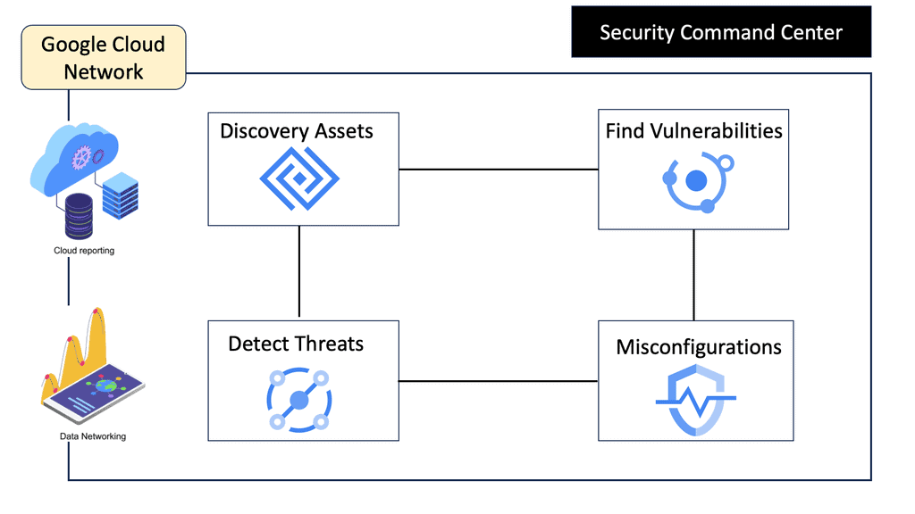
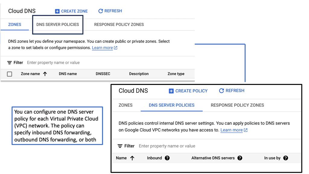
Once a specific flow entry matches a packet, you can specify the number of actions. Options include output to the port type: NORMAL port for traditional processing, LOCAL PORT for the local control plane, and CONTROLLER port for sending to the controller.

In addition, you may set the OUTPUT QUEUE ID, PUSH/POP VLAN, MPLS, or PBB tags. You can even do a header rewrite, which means OpenFlow can be used to implement NAT. However, be careful with this, as you only have a limited number of flow entries on the switches. Finally, some actions might be in software, which is too slow.

OpenFlow Groups

Finally, there is an exciting mechanism where a packet can be processed through what is known as a GROUP. With OpenFlow 1.1+, the OpenFlow forwarding model included the functionality of GROUPS. Groups enhance the previous OpenFlow forwarding model. However, enhanced forwarding mechanisms like ECMP Load Balancing cannot be completed in OpenFlow 1.0. For this reason, the ONF implemented OUTPUT GROUPS.

A Group is a set of buckets, and a Bucket is a set of actions. For example, an action could be output to port, set VLAN tag, or push/pop MPLS tag. Groups can contain several buckets; bucket 1 could be sent to port 1, and bucket 2 to port 2, but it could also add a tag.

This adds granularity to OpenFlow forwarding and enables additional forwarding methods. For example, sending to all buckets in a group could be used for selective multicast, or sending to one bucket in a group could be used for load balancing across LAG or ECMP.

Final Points: OpenFlow Protocol

OpenFlow Protocol represents a significant advancement in network management, offering a more flexible, programmable, and efficient approach. Decoupling the control and forwarding plane enables centralized control, programmability, and network virtualization. With its wide range of benefits and use cases, OpenFlow Protocol is poised to revolutionize network management and pave the way for future innovations in networking technologies.

As organizations face ever-increasing network challenges, embracing OpenFlow Protocol can provide a competitive edge and drive efficiency in network operations.

Summary: OpenFlow Protocol

The introduction of the OpenFlow protocol has witnessed a remarkable revolution in the world of networking. In this blog post, we will delve into its intricacies and explore how it has transformed the way networks are managed and controlled.

Understanding OpenFlow

At its core, OpenFlow is a communication protocol that enables the separation of control and data planes in network devices. Unlike traditional networking approaches, where switches and routers make forwarding decisions, OpenFlow centralizes the control plane, allowing for dynamic and programmable network management.

The Key Components of OpenFlow

To grasp the power of OpenFlow, it is essential to understand its key components. These include the OpenFlow switch, which processes packets based on instructions from a centralized controller, and the controller, which has a comprehensive view of the network topology and makes intelligent decisions on forwarding packets.

Benefits and Advantages

OpenFlow brings forth a myriad of benefits to networking environments. Firstly, it promotes flexibility and programmability, allowing network administrators to tailor the behavior of their networks to meet specific requirements. Furthermore, it simplifies network management, as policies and configurations can be implemented centrally. Additionally, OpenFlow enables network virtualization, enhancing scalability and resource utilization.

Real-World Applications

The adoption of OpenFlow has paved the way for innovative networking solutions. Software-defined networking (SDN) is one application where OpenFlow is critical. SDN allows for dynamic network control and management, making implementing complex policies and responding to changing network conditions easier.

In conclusion, the OpenFlow protocol has brought a paradigm shift in the networking world. Its ability to separate control and data planes, along with its flexibility and programmability, has transformed how networks are designed, managed, and controlled. As technology continues to evolve, OpenFlow and its applications, such as SDN, will undoubtedly play a pivotal role in shaping the future of networking.