Neutron Network

Neutron Network

In today's interconnected world, the importance of a robust and efficient network infrastructure cannot be emphasized enough. One technology that has been making waves in the networking realm is Neutron Network. In this blog post, we will delve into the intricacies of Neutron Network and explore its potential to bridge the digital divide.

Neutron Network, a component of OpenStack, is a software-defined networking (SDN) project that provides networking capabilities as a service for other OpenStack services. It enables the creation and management of virtual networks, routers, and security groups, offering a flexible and scalable solution for network infrastructure.

Neutron Network offers a wide range of features that make it an ideal choice for modern network deployments. From network segmentation and isolation to load balancing and firewall services, Neutron Network empowers administrators with granular control and enhanced security. Additionally, its integration with other OpenStack components allows for seamless management and orchestration of the entire infrastructure.

The versatility of Neutron Network opens up a plethora of use cases across various industries. In the realm of cloud computing, Neutron Network enables the creation of virtual networks for tenants, ensuring isolation and security. It also finds applications in data centers, enabling efficient traffic routing and load balancing. Moreover, with the rise of edge computing, Neutron Network plays a crucial role in connecting distributed devices and facilitating real-time data transfer.

While Neutron Network offers a plethora of advantages, it is essential to acknowledge and address the challenges it may pose. Some common limitations include complex initial setup, scalability concerns, and potential performance bottlenecks. However, with proper planning, optimization, and ongoing development, these challenges can be mitigated, ensuring a smooth and efficient network infrastructure.

Conclusion: Neutron Network emerges as a powerful tool in bridging the digital divide, empowering organizations to build robust and flexible network infrastructures. With its extensive features, seamless integration, and diverse applications, Neutron Network paves the way for enhanced connectivity, improved security, and efficient data transfer. Embracing this technology can unlock new possibilities and propel businesses into the future of networking.

Highlights: Neutron Network

The need for virtual networking

Due to the proliferation of devices in data centers, today’s networks contain more devices than ever. Servers, switches, routers, storage systems, and security appliances are now available as virtual machines and virtual network appliances. A scalable, automated approach is needed to manage next-generation networks. Thanks to its flexibility, control, and provisioning time, users can control their infrastructure more easily and quickly with OpenStack.

OpenStack Networking is a pluggable, scalable, API-driven system that manages networks and IP addresses on OpenStack clouds. Like other core OpenStack components, It allows users and administrators to maximize the value and utilization of existing data center resources. Unlike Nova (computing), Glance (images), Keystone (identity), Cinder (block storage), or Horizon (dashboard), Neutron (Networking) is a stand-alone service. To provide resiliency and redundancy, OpenStack Networking can be configured to run on a single server or distributed across multiple hosts.

With OpenStack Networking, users can request additional processing through an application programmable interface or API. Cloud operators can enhance and power the cloud by defining network connectivity in the cloud with different networking technologies. Access to a database is required for Neutron to store network configurations persistently.

Application Program Interface

Neutron’s pluggable application program interface ( API ) architecture enables the management of network services for container networking in public or private cloud environments. The API allows users to interact with neutron networking constructs, such as routers and switches, enabling instance reachability. The OpenStack Neutron and OpenStack network types were initially built into Nova but lacked flexibility for advanced designs. It was helpful for large Layer 2 networks, but most environments require better multi-tenancy with advanced load balancing and firewalling functionality.

Decoupled Layer 3 Approach

The limited networking functionality gave Neutron, which offers a decoupled Layer 3 approach. It operates an Agent-Database model where the API receives and sends calls to agents installed locally on the hosts. Without this efficiency, there won’t be any communication and connectivity between your host’s platforms, which can sometimes affect productivity.

For additional pre-information, you may find the following helpful:

  1. OpenStack Neutron Security Groups
  2. Kubernetes Network Namespace
  3. Service Chaining


OpenStack Network Types.

Key Neutron Network Discussion points:


  • Introduction to Neutron Networking.

  • Discussion on OpenStack Network Types.

  • Virtual switches, routing and advanced services with Neutron.

  • Neutron High Availability.

  • Discussion on traffic flow.

Back to Basics: Neutron Network

Key Features and Benefits:

1. Network Virtualization: Neutron Network leverages network virtualization technologies such as VLANs, VXLANs, and GRE tunnels to create isolated virtual networks. This allows tenants to have complete control over their network resources without interference from other tenants.

2. Scalability: Neutron’s distributed architecture can scale horizontally to accommodate many virtual networks and instances. This ensures that cloud environments can handle increased workloads without compromising performance.

3. Network Segmentation: Neutron Network supports network segmentation, allowing tenants to partition their virtual networks based on specific requirements. This enables better network isolation, security, and performance optimization.

4. Flexible Network Topologies: Neutron provides the flexibility to create a variety of network topologies, including flat networks, VLAN-based networks, and overlay networks. This adaptability empowers users to design their networks according to their unique needs.

5. Integration with Security Services: Neutron Network integrates seamlessly with OpenStack’s security services, such as Firewall-as-a-Service (FWaaS) and Virtual Private Network-as-a-Service (VPNaaS). This integration enhances network security by providing additional layers of protection.

6. Load Balancing and VPN Services: Neutron Network offers load balancing services, allowing users to distribute network traffic across multiple instances for improved performance and reliability. Additionally, it supports VPN services to establish secure connections between different networks or remote users.

Neutron Network Architecture:

Under the hood, Neutron Network consists of several components working together to provide a robust networking service. The main elements include:

– Neutron API: Provides a RESTful API for users to interact with Neutron Network and manage their network resources.

– Neutron Core Plugin: The central component responsible for handling network-related requests and managing network plugins.

– Neutron Agents: Various agents, such as the DHCP agent, L3 agent, and OVS agent, ensure the smooth operation of the Neutron Network by handling specific tasks like DHCP allocation, routing, and switching.

– Network Plugins: Neutron supports multiple plugins, such as the Open vSwitch (OVS) plugin and the Linux Bridge plugin, which provide different network virtualization capabilities and integrate with various networking technologies.

OpenStack Network Types

Logical network information is stored in the database. Plugins and agents extract the data and carry out the necessary low-level functions to pin the virtual network, enabling instance connectivity. For example, the Open vSwitch agent converts information in the Neutron database to Open vSwitch flow while maintaining the local flows to match the network design following topology changes. Agents and plugins build the network based on the logical data model. The screenshot below illustrates the agent-to-host installation.

openstack network types

Neutron Networking: Network, Subnets, and Ports

Neutron consists of four elements that form the foundation for OpenStack Network Types. The configuration consists of the following entities: Networks, Subnets, and Ports. A network is a standard Layer 2 broadcast domain in which subnets and ports are assigned. A subnet is an IPv4 or IPv6 address block ( IPAM—IP Address Management) posted to a network.

A port is a connection point with properties similar to those of a physical port, except that it is virtual. Ports have media access control addresses ( MAC ) and IP addresses. All port information is stored in the Neutron database, which plugins/agents use to stitch and build the virtual infrastructure. 

Neutron networking features

Neutron networks enable core networking and the potential for much more once the appropriate extension and plugin are activated. Extensions enhance plugins to provide additional network functionality. Due to its pluggable architecture, Neutron can be extended with third-party open-source or proprietary products, for example, an SDN OpenDaylight controller for advanced centralized functionality. 

While Neutron does offer an API for network interaction, it does not provide an API to manage the network. Integrating an SDN controller with Neutron enables a centralized viewpoint and management entity for the entire network infrastructure, not just individual pieces.

Some vendor plugins complement Neutron, while others completely replace it. Advancements have been made to Neutron in an attempt to make it more “production-ready,” but some of these features are still at the experimental stage. There are bugs in all platforms, but generally, early-release features should be kept in nonproduction environments.

Virtual switches, routing, and advanced services

Virtual switches are software switches that connect VM instances at Layer 2. Any communication outside that boundary requires a Layer 3 router, either physical or virtual. Neutron has built-in support for Linux Bridges and Open vSwitch virtual switches. Overlay networking, the foundation for multi-tenancy for cloud computing, is supported in both. 

Layer 3 routing permits external connectivity and connectivity between VMs in different subnets. Routing is enabled through IP forwarding rules, IPtables, and network namespaces.

IPtables provide ingress/egress filtering throughout different parts of the network (for example, perimeter edge or local compute ), namespaces provide network stack isolation, and IP forwarding rules provide forwarding. Firewalling and security services are based on Security Groups or FWaaS (FireWall-as-a-Service).

They can be used in conjunction for better depth defense. Both operate with IPtables but differ in network placement.

Security group IPtable rules are configured locally on ports corresponding to the compute node hosting the instance. Implementation is close to the actual workload, offering finer-grained filleting. Firewall IPtable rules are at the network’s edge on Neutron routers ( namespaces ), filtering perimeter traffic.

Load balancing enables requests to be distributed to multiple instances. Dispersing load to numerous hosts offers advantages similar to those of the traditional world. The plugin is based on open-source HAProxy. Finally, VPNs allow operators to extend the network securely with IPSec-based VPN tunnels. 

Virtual network preparation

The diagram below displays the initial configuration and physical interface assignments for a standard neutron deployment. The reference model consists of a controller, network, and compute nodes. The compute nodes are restricted to provide compute resources, while the controller/network node may be combined or separated for all other services.

Separating services on the compute nodes allows compute services to be scaled horizontally. It’s common to see the controller and networking node operating on a single host.

Service OpenStack

The number and type of interfaces depend on how good you feel about combining control and data traffic. Networking can function with just one interface, but splitting the different kinds of network traffic into several separate interfaces is good.

OpenStack Network Types uses four types of traffic – Management, API, External, and Guest. If you are going to separate anything, it’s recommended to physically separate management and API traffic from all other types of traffic. Separating the traffic to different interfaces splits the control from data traffic—a tick from the security auditors’ box.

Neutron Reference Design

The preceding diagram, Eth0 is used for the management and API network, Eth1 for overlay traffic, and Eth2 for external and Tenant networks ( depending on the host ). The tenant networks ( Eth2 ) reside on the compute nodes, and the external network resides on the controller node ( Eth2 ).

The controller Eth2 interface uses Neutron routers for external network traffic to instances. In certain Neutron Distributed Virtual Routing ( DVR ) scenarios, the external networks are at the compute nodes.

Plugins and drivers

Neutron networking operates with the concept of plugins and drivers. Neutrons core plugin can be either an ML2 or a vendor plugin. Before ML2, Neutron was limited to a single-core plugin at any given time. The ML2 plugin introduces the concept of type and mechanism drivers.

Type drivers represent type-specific network states and support local, flat, vlan, gre, and vxlan network types. Mechanism drivers take information from the type driver and ensure its implementation correctly.

There are agent-based, controller-based, and Top-of-Rack models of the mechanism driver. The most popular are the L2 population, Open vSwitch, and Linux bridge. In addition, the mechanism driver arena is a popular space for vendors’ products.

Linux Namespaces

The majority of environments require some multi-tenancy. Cloud environments would be straightforward if built for only one customer or department. In reality, this is never the case. Multi-tenancy within Neutron is based on Linux Namespaces. Namespace offers a completely isolated stack to do what you want. They enable a logical copy of the network stack supporting overlapping IP assignments.

A lot of Neutron networking is made possible with the use of namespaces and the ability to connect them.

We have a qdhcp namespace, qrouter namespace, qlbass namespace, and additional namespaces for DVR functionality. Namespaces are present on nodes running the respective agents. The following command displays different routing tables for NAMESPACE-A and the global namespace, illustrating the ability of network stack isolation.

Linux namespace

OpenStack Network Types: Virtual network infrastructure

Local, Flat, VLAN, VXLAN, and GRE networks

Neutron networking supports Local, Flat, VLAN, VXLAN, and GRE networks. Local networks are isolated networks. Flat networks do not incorporate any VLAN tagging. On the other hand, VLAN networks use the standard. Q tagging ( IEEE 802.1Q ) to segregate traffic. VXLAN networks encapsulate Layer 2 traffic over IP using VTEP and VXLAN network identifier ( VNI ).

GRE is another type of Layer 2 over Layer 3 overlay. Both GRE and VXLAN accomplish the same goal of emulation over pure IP but use different methods —VXLAN traffic uses UDP, and GRE traffic uses IP protocol 47.

Layer 2 data is transported from an end host, encapsulated over IP to the egress switch that sends the data to the destination host. With an underlay and overlay approach, you have two layers to debug when something goes wrong.

openstack network types

OpenStack Network Types: Virtual Network Switches

The first step in building a virtual network is to make the virtual switching infrastructure. This acts as the base for any network design, whether virtual or physical. Virtual switching provides connectivity to and from the virtual instances, building the concrete for advanced networking services. The first piece of the puzzle is the virtual network switches.

Neutron networking includes built-in support for the Linux Bridge and Open vSwitch. Both are virtual switches but operate with some significant differences. The Linux bridge uses VLANs to tag traffic, while the Open vSwitch uses flow rules to manipulate traffic before forwarding.

Instead of mapping the local VLAN ID to a physical VLAN ID, the local ID is added or stripped from the Ethernet header by flow rules.

The “brctl show” command displays the Linux bridge. The bridge ID is automatically generated based on the NIC, and the bridge name is based on the UUID of the corresponding Neutron network. The “ovs-vsctl show” command displays the Open vSwtich. It has a slightly more complicated setup, with the br-int ( integration bridge ) acting as the main center point of connections.

openstack network types

Neutron uses the bridge, 802.1q, and vxlan kernel modules to connect instances with the Linux bridge. Bridge and Open vSwitch kernel modules are used for the Open vSwitch. The Open vSwitch uses some userspace utilities to manage the OVS database. Most networking elements are connected with virtual cables, known as veth cables. What goes in one end must come out; the other best describes a virtual cable.

Veths connect many elements, including namespace to the namespace, Open vSwitch to Linux bridge, and Linux bridge to Linux bridge, all combined with veth cables. The Open vSwitch uses additional particular patch ports to connect Open vSwitch bridges. The Linux bridge doesn’t use patch ports.

The Linux Bridge and Open vSwitch can complement each other. For example, when Neutron Security Groups are enabled, instances connect to the Linux and Open vSwitch Integration bridges with a Veth cable. The workaround is caused by the inability to place IPtable rules ( needed by security groups ) on tap interfaces connected to Open vSwitch bridge ports. 

Neutron network and network address translation (NAT)

Neutron employs the concept of Network Address Translation (NAT) to predict inbound and outbound translations. The concept of NAT stays the same in the virtual world, either by modifying an IP packet’s source or destination address. Neutron employs two types of translations – one-to-one and one-to-many.

One-to-one translations utilize floating IP addresses, and many-to-one is a Port Address Translation ( PAT ) style design where floating IP is not used. F

Floating IP addresses are externally routed IP addresses that directly map instances and an external IP address. The term floating comes from the fact that they can be modified on-the-fly between instances. They are associated with a Neutron port logically mapped to an example. Ports can have multiple IP addresses assigned.

    • SNAT refers to source NAT, which changes the source IP address to appear as the externally connected interface.
    • Floating IPs are called Destination NAT ( DNAT ), which change the source and destination IP address depending on traffic direction.

The external network connected to the virtual router is the network from which floating IPs are derived. The default behavior is to source NAT traffic from instances that lack floating IP. Instances that use source NAT can not accept traffic initiated externally. If you want traffic created externally to hit an instance, you must use a one-to-one mapping with a floating IP.

Neutron High Availability

Standalone router

The most accessible type of router to create in Neutron is a standalone router. As the name suggests, it lacks high availability. Routers created with Neutron exist on namespaces that reside on the nodes running the L3 agent. It is the role of the Layer 3 agent to create the network namespace representing the routing function.

A virtual router is essentially a network namespace called the qrouter namespace. The qrouter namespace uses routing tables to forward traffic and IPtable rules to dictate how traffic is translated.

neutron networking

A virtual router can connect to two different types of networks: a single external provider network or one or more tenant networks. The interface to an external provider bridge network is “qg,” and to a tenant network bridge is a “qr” interface. The tenant network traffic is routed from the “qr” interface to the “qg” interface for onward external forwarding.

Virtual router redundancy protocol

VRRP is pretty simple and offers highly available and redundant default gateways or the next hop of a route. The namespaces ( routers ) are spread across multiple hosts running the Layer 3 agent. Multiple router namespaces are created and distributed among the Layer 3 agents. VRRP operates with a Linux keepalive instance. Each runs a “keepalive” service to detect the other’s availability.

The keepalive service is a Linux keepalive tool that uses VRRP internally. It is the role of the L3 agent to start the keepalive instance on every namespace. A dedicated HA network allows the routers to talk to each other. There are split-brain and MAC flapping issues; as far as I understand, it’s still an experimental feature. 

Distributed virtual routing 

DVR eliminates the bottleneck caused by the Layer 3 agent and distributes most of the routing function across multiple compute nodes. This helps isolate failure domains and increases the high availability of the virtual network infrastructure. With DVR, the routing function is not centralized anymore but decentralized to the compute nodes. The compute nodes themselves become one big router.

DVR routers are spawned on the compute nodes, and all the routing gets done closer to the workload. Distributing routing to the compute nodes is much better than having a central element perform the routing function.

There are two types of modes: dvr and dvr_snat. Mode dvr_snat handles north-to-south SNAT traffic. Mode DVR handles north-to-south DNAT traffic ( floating IP) and all east-to-west traffic.

Key Points:

  • East-West traffic ( server to server ) previously went through the centralized network node. DVR pushes this down to the compute nodes hosting the VMs.
  • North-South traffic with floating IPs ( DNAT ) is routed directly by the compute nodes hosting the VMs.
  • North-South traffic without floating IP ( SNAT ) is routed through a central network node. Distributing the SNAT functions to the local compute nodes can be complicated.
  • DNAT is required to compute nodes using floating IPs that require direct external connectivity.

East-west traffic between instances

East-to-west traffic (traditional server-to-server) refers to local communication, such as traffic between a frontend and the backend application tier. DVR enables each compute node to host a copy of the same router. The router namespace created on each compute node has the same interface, MAC, and IP settings.

East West traffic

DVR East to WestNEWDVR East to West

The qr interfaces within the namespaces on each compute node share the same IP and MAC address. But how is this possible?? One can assume the distribution of ports would raise IP clashes and MAC flapping. Neutron cleverly uses routing tables and Open vSwitch flow rules to enable this type of forbidden sharing.

Neutron allocates each compute node a unique MAC address, which is used whenever traffic leaves the node.

Once traffic leaves the virtual router, Open vSwitch rules rewrite the source MAC address with the unique MAC address allocated to the source node. All the manipulation is done before and after traffic leaves or enters, so the VM is unaware of any rewriting and operates as usual.

Centralized SNAT 

Source SNAT is used when instances do not have a floating IP address. Neutron decided not to distribute SNAT to the compute nodes and kept it central, similar to the legacy model. Why did they decide to do this when DVR distributes floating IP for north-south traffic?

Decentralizing SNAT would require an address from the external network on every node providing the SNAT service. This would consume a lot of addresses on your external network.

centralized SNAT

The Layer 3 agent configured as dvr_snat server is the centralized SNAT function. Two namespaces are created for the same router—a regular qrouter namespace and an SNAT namespace. The SNAT and qrouter namespaces are created on the centralized nodes, either the controller or the network node.

The qrouter namespaces on the controller and compute nodes are identical. However, even though the router is attached to an external network, there are no qg interfaces. The qg interfaces are now inside the SNAT namespace. There is also now a new interface called the sg. This is used as an extra hop.


Packet Flow

  • A VM without a floating IP sends a packet to an external destination.
  • Traffic arrives at the regular qrouter namespace on the actual node and gets redirected to the SNAT namespace on the central node.
  • To redirect traffic from the qrouter namespace to the SNAT namespace is carried out by clever tricks with source routing and multiple routing tables.

 North-to-south traffic with Neutron floating IP

In the legacy world, floating IPs are configured as /32 prefixes on the router’s external device. The one-to-one mapping between the VM IP address and the floating IP address is used so external devices can initiate external traffic to the internal instance.

North-to-south traffic with floating IP is now handled with another namespace called the fip namespace. The new fip namespace is created by the Layer 3 agent and represents the external network to which the fip belongs.

distributed virtual routing

Every router on the compute node is hooked into the new fip namespace with a veth pair. Veth pairs are commonly used to connect namespaces. One side of the other pair is in the router namespace (rfp), and the other end belongs to the fip namespace (fpr).

Whenever a layer 3 agent creates a new floating IP, a new rule is specific to that IP. Neutron adds the fixed IP of the VM to the rules table with an additional new routing table.

Packet Flow

  • When a VM with a floating IP sends traffic to an external destination, it arrives at the qrouter namespace.
  • The IP rules are consulted, showing a default route for that source to the next hop. IPtables rules kick in, and the source IP is translated to the floating IP.
  • Traffic is forwarded out the rfp interface and arrives at the fpr interface at the fip namespace.
  • The fip namespace uses a default route to forward traffic out the ‘fg’ device to its external destination.

Traffic in the reverse direction requires Proxy ARP, so the fip namespace answers requests for the floating IP configured on the router’s router namespace ( not the fip namespace ). In addition, proxy ARP enables hosts ( fip namespace) to answer ARP requests intended for other hosts ( qrouter namespace ).

Summary: Neutron Network

Neutron Network, a fundamental component of OpenStack, is pivotal in connecting virtual machines and providing networking services within a cloud infrastructure. In this blog post, we delved into the intricacies of the Neutron Network and explored its key features and benefits.

Section 1: Understanding Neutron Network Architecture

Neutron Network operates with a modular architecture comprising various components such as agents, plugins, and drivers. These components work together to enable network virtualization, creating virtual networks, subnets, and routers. By understanding the architecture, users can leverage the full potential of the Neutron Network.

Section 2: Network Virtualization with Neutron

One of the standout features of Neutron Network is its ability to provide network virtualization. By abstracting the underlying physical network infrastructure, Neutron empowers users to create isolated virtual networks tailored to their specific requirements. This flexibility allows for enhanced security, scalability, and agility within cloud environments.

Section 3: Neutron Network Extensions

Neutron Network offers many extensions that cater to diverse networking needs. From load balancers and firewalls to virtual private networks (VPNs) and quality of service (QoS) policies, these extensions provide additional functionality and customization options. We explored some popular extensions and their use cases.

Section 4: Neutron Network in Action: Use Cases

To truly comprehend the value of Neutron Network, it’s essential to explore real-world use cases where its capabilities shine. This section delved into scenarios such as multi-tenant environments, hybrid cloud deployments, and network function virtualization (NFV). By examining these use cases, readers can envision the practical applications of the Neutron Network.

Conclusion:

Neutron Network is a vital networking component within OpenStack, enabling seamless connectivity and virtualization. With its modular architecture, extensive feature set, and wide range of use cases, Neutron Network empowers users to build robust and scalable cloud infrastructures. As cloud technologies evolve, Neutron Network ensures efficient and reliable networking within cloud environments.

OpenvSwitch Performance

OpenvSwitch Performance

In today's rapidly evolving digital landscape, network performance is a crucial aspect for businesses and organizations. To meet the increasing demands for scalability, flexibility, and efficiency, many turn to OpenvSwitch, an open-source virtual switch that provides advanced network capabilities. In this blog post, we will explore the various ways OpenvSwitch enhances network performance and the benefits it offers.

OpenvSwitch, also known as OVS, is a software-based switch that enables network virtualization and software-defined networking (SDN). It operates at the data link layer and allows for the creation of virtual networks, connecting virtual machines and containers across physical hosts. OVS offers a range of features, including VLAN tagging, tunneling protocols, and flow-based forwarding, making it a powerful tool for network administrators.

Improved Network Throughput: One of the key advantages of OpenvSwitch is its ability to enhance network throughput. By leveraging hardware offloading capabilities and utilizing multiple CPU cores efficiently, OpenvSwitch can handle higher traffic volumes with reduced latency. Additionally, OVS supports advanced packet processing techniques, such as DPDK (Data Plane Development Kit), which further improves performance in high-speed networking scenarios.>

Dynamic Load Balancing: Another notable feature of OpenvSwitch is its support for dynamic load balancing. OVS intelligently distributes network traffic across multiple physical or virtual links, ensuring efficient utilization of available resources. This load balancing capability helps to prevent network congestion, optimize network performance, and improve overall system reliability.

Network Monitoring and Analytics: OpenvSwitch provides comprehensive network monitoring and analytics capabilities. It supports integration with monitoring tools like sFlow and NetFlow, allowing administrators to gain insights into network traffic patterns, identify bottlenecks, and make informed decisions for network optimization. Real-time visibility into network performance metrics enables proactive troubleshooting and facilitates better network management.

Conclusion: OpenvSwitch is a powerful tool for enhancing network performance in modern computing environments. With its advanced features, including improved throughput, dynamic load balancing, and robust monitoring capabilities, OpenvSwitch empowers network administrators to optimize their infrastructure for better scalability, efficiency, and reliability. By adopting OpenvSwitch, organizations can stay ahead in the ever-evolving world of networking.

Highlights: OpenvSwitch Performance

The virtual world of networking

Virtualization requires an understanding of how virtual networking works. Without virtual networking, justifying the costs would be very difficult. You can run multiple virtual machines using a virtualization host, each with its dedicated physical network port. By implementing virtual networking, we can consolidate networking in a more manageable way regarding cost and administration. We can use an approximate metaphor if you are familiar with VMware-based networking – Open vSwitch is similar to vSphere Distributed Switch.

The implementation of Open vSwitch consists of the kernel module (the data plane) and the user-space tools (the control panel). The data plane was moved into the kernel to process incoming data packets as fast as possible. The switch daemon implements and manages several OVS switches using the Netlink socket.

There is no specific SDN controller

Unlike VMware’s NSX and vSphere distributed switches, Open vSwitch has no specific SDN controller to manage its capabilities. Several NSX components are used, including vCenter. OVS controls an SDN controller from another company that uses the OpenFlow protocol using ovs-vswitchd. The OVSDB server maintains a switch table database that external clients can access via JSON-RPC. The persistent database ovsdb, designed to survive restarts, currently has around 13 tables.

Many clients prefer VMware’s NSX approach to SDN and Open vSwitch. VMware’s integration with OpenStack and NSX integration with Linux-based KVM hosts (via Open vSwitch and additional agents) can be beneficial. As an example of the use of Open vSwitch-based technologies in NSX, there are things such as hardware VTEP integration through Open vSwitch Database, GENEVE networks being extended to KVM hosts using Open vSwitch/NSX integration, etc.

OVS Performance

Bridges and Flow Rules

Open vSwitch is a software switch commonly seen in Open Networking used to connect physically to virtual interfaces. When considering OpenvSwitch’s performance, it uses virtual bridges and flow rules to forward packets and consists of several switches, including provider, integration, and tunnel bridge. Each virtual switch has a different role in the network—the tunnel bridge creates the overlay, and the integration switch is the leading connectivity bridge.

OVS Bridge

The terms bridge and switch are used interchangeably with Neutron networking. The OVS bridge has user actions issued in userspace and a set of flows programmed in the Linux kernel with match criteria and actions. The kernel module is where all the packet processing occurs, similar to an ASIC on a standard physical/hardware switch.

The OVS has its daemon as the userspace element, running in userspace, controlling how the kernel gets programmed. It also uses an Open vSwitch Database Server (OVSDB), a network configuration protocol.

For additional information, you may find the following helpful:

  1. ACI Cisco 
  2. OpenFlow Protocol
  3. Network Functions
  4. Testing Packet Loss
  5. Neutron Networks
  6. OpenStack Neutron 
  7. OpenStack Neutron Security Groups


OpenvSwitch Performance.

Key OpenvSwitch Performance  Discussion points:


  • Introduction to OpenvSwitch Performance.

  • Discussion on Stateless vs stateful functionality.

  • Integrations with OpenvSwitch.

  • NetFilter Framework.

Back to Basics With OVS

Highlighting the OVS

OVS is an essential part of networking in the OpenStack cloud. Open vSwitch is not a part of the OpenStack project. However, OVS is used in most implementations of OpenStack clouds. It has also been integrated into other virtual management systems, including OpenQRM, OpenNebula, and oVirt. Open vSwitch can support protocols such as OpenFlow, GRE, VLAN, VXLAN, NetFlow, sFlow, SPAN, RSPAN, and LACP. In addition, it can work in distributed configurations with a central controller.

1. High Throughput: OpenvSwitch is known for its high throughput capabilities, which allow it to handle a large volume of network traffic without compromising performance. By leveraging hardware offloading and advanced flow processing techniques, OpenvSwitch ensures optimal packet processing and forwarding, reducing latency and maximizing network efficiency.

2. Flexible Load Balancing: Load balancing is crucial in modern networks to distribute traffic evenly across multiple network paths, preventing congestion and maximizing network utilization. OpenvSwitch supports various load balancing algorithms, including Layer 2, Layer 3, and Layer 4 load balancing, enabling organizations to achieve efficient traffic distribution and enhance network performance.

3. Scalability: OpenvSwitch provides excellent scalability, allowing organizations to expand their network infrastructure seamlessly. With OpenvSwitch, network administrators can easily add new virtual machines, containers, or hosts without disrupting the overall network performance. This flexibility ensures that organizations can adapt to changing network requirements without compromising performance.

4. Network Virtualization: OpenvSwitch supports network virtualization, enabling the creation of virtual network overlays. These overlays help improve network agility and efficiency by allowing organizations to isolate and manage different network segments independently. By leveraging OpenvSwitch’s network virtualization capabilities, organizations can optimize network performance and enhance network security.

5. Integration with SDN Controllers: OpenvSwitch can seamlessly integrate with Software-Defined Networking (SDN) controllers, such as OpenDaylight and OpenStack, providing centralized network management and control. This integration allows organizations to automate network provisioning, configuration, and optimization, improving network performance and operational efficiency.

6. Monitoring and Analytics: OpenvSwitch offers extensive monitoring and analytics capabilities, allowing organizations to gain valuable insights into network performance and traffic patterns. By leveraging these features, network administrators can identify bottlenecks, optimize network configurations, and proactively address performance issues, improving network efficiency.

Highlighting OpenvSwitch Performance

Linux Networking Subsystem

Initially, OpenvSwitch’s performance was good with steady-state traffic. The kernel was multithreaded, so established flows performed excellently. However, specific traffic patterns would give OpenvSwitch a headache and degrade its performance.

For example, peer-to-peer applications initiating many quickly generated connections would hit it poorly.

This is because the kernel contained recently cached flows, and when a packet that wasn’t an exact cache match would result in a cache miss and get sent to userspace. In addition, continuous user-kernel space interaction kills performance.

Unlike the kernel, userspace is single-threaded and does not have the performance to process large amounts of packets or set up connections quickly.

They needed to improve the OpenvSwitch performance of the connection setup. So they added Megaflow and wildcard entries in the kernel, made userspace multithreaded, and introduced various enhancements to the classifier. They have spent much time putting mega flows in the kernel and don’t want to undo all that good work. This is a foundation design principle to support stateful service and connection tracking implementation. Anything they add to Open vSwitch must not affect performance.  

Stateless vs. stateful functionality

It’s an excellent stateless flow-forwarding device and supports finer-grained flow fields, but there is a gap in supporting stateful services. They are currently expanding their feature set to include stateful connection tracking, stateful inspection firewall, and deep packet inspection services.

The current matching enables you to match IP and port numbers. Nothing higher up the application stack, such as application ID, is used. Stateless services offer better protection than stateless services as it delves deeper into the packet.

What is a stateless function?

Stateless means once a packet arrives, the device can only affect what’s currently in that packet. It looks at the headers and bases the policy on those it just inspected. Evaluation is performed on packet contents statically and is unaware of any data patterns.

Typically, stateless inspects the following elements within a packet – source/destination IP, source/destination port, and protocol type. No additional Layer 3 or 4 inspection, such as TCP control flags, sequence numbers, and ACK fields, is carried out.

For example, if the requirement involves matching on a TCP window parameter, stateless tracking won’t be able to track if packets are within a specific window. Regarding Network Address Translation (NAT), performing stateless translation from one IP address to another is possible, as well as adjusting the MAC address for external forwarding, but it won’t handle anything complicated.

Today’s security requires more advanced filtering than Layer 3 and 4 headers. The stateful function watches everything end-to-end and knows precisely the TCP connection’s stage. This enables more detailed information than source/destination IP or port numbers. 

Connection tracking is fundamental to the stateful virtual firewall and supports enhanced NAT functionality. We need to consider when traffic is based on sessions and filter according to other parameters, such as a connection’s state.

The stateful inspection goes deeper and tracks every connection, examining the packet headers and the application layer information in the payload. Stateful devices can determine if a connection has been negotiated, reset, established, and closed.

In addition, it provides complete protection against many high-level attacks by allowing administrators to be specific with their filtering, such as not allowing the peer-to-peer (P2P) application to be transferred over HTTP tunnels.

Traditionally, Open vSwitch has two stateless approaches to firewalling:

Match on TCP flags

The ability to match on TCP flags and enforce policy on the SYN packets, permitting ALL ACK and RST. This approach gains in performance due to cached entries existing in the kernel. Keeping as much as possible in the kernel limits cache misses and user space interaction.

What it gains in performance is what it lacks in security. It is not very secure, as you allow ANY packet with an ACK or RST bit set. It will enable non-established flows through with ACT or RST set. An attacker could quickly probe with a standard TCP port scanning tool, sending an ACK in and examining received responses. 

Use the “learn” action.

The Open vSwitch ovs-vswitchd process default acts like a standard bridge and learns MAC addresses. It will continue to connect to the controller in the background, and when it succeeds, it will stop acting like a traditional MAC-learning switch. The userspace element maintains MAC tables and generates flows with matches and actions. This allows new OpenFlow rules to be inserted into userspace.

When a packet arrives, it gets pushed to userspace, and the userspace function uses the “learn” action to create the reverse of the five tuples, inserting a new flow into the OpenFlow table. The process comes at a performance cost and is not as quick as having an existing connection. It forces every new flow into userspace.

These methods are sufficient for some network requirements but don’t carry out any deep actions on TCP to ensure there are no overlapping segments, for example. In addition, they cannot inspect related flows to support complex protocols like FTP and SIP, which have different flows for data and control.

The control channel negotiates with the remote end of the data flow configuration. For example, the client initiates a TCP port 21 control connection with FTP. The remote FTP server then opens up a data socket on port 20.

OpenvSwitch Performance: Contract integration with Open vSwitch

The Open vSwitch team proposes using the conntrack module in Linux to enable stateful services. This is an alternative to using Linux Bridge with IPtables. 

Contract stores the state of all connections and informs the Netfilter framework of the connection state. Transit packets are connection tracked in the PRE_ROUTING chain, and anything locally generated is performed in the OUTPUT chain. Packets may have four userland states: NEW, ESTABLISHED, RELATED, and INVALID. Outside of the userland state, we have packet states in the kernel; for example, TCP SYN_SENT lets us know we have only seen a TCP SYN in one direction.

If the conntrack sees one SYN packet, it considers the packet new. Once it sees a return TCP SYN/ACK, it thinks the connection is established, and data can be transmitted. Once a return packet is received, the packet state changes to ESTABLISHED in the PRE_ROUTING chain of the nat table.

The Open vSwitch can call into the kernel connection tracker. This will allow stateful tracking of flows and also the support of Application Layer Gateway (ALG) to punch holes for related “data” channels needed for protocols like FTP and SIP.

Netfilter Framework

A fundamental part of connection tracking is the Netfilter framework. The Netfilter framework provides a variety of functionalities – packet selection, packet filtering, connection tracking, and NAT. In addition, the Netfilter framework enables callbacks in the packet traversing the network stack.

These callbacks are known as Netfilter hooks, which enable an operation on the packet. The essence of Netfilter is the ability to activate hooks.

They are called upon at distinct points along with packet traversal in the kernel. The five points in the network stack where you can implement hooks include NF_INET_PRE_ROUTING, NF_INET_LOCAL_IN, NF_INET_FORWARD, NF_INET_POST_ROUTING, NF_INET_LOCAL_OUT. Once a packet comes in and passes initial tests ( checksum, etc.), they are passed to the Netfilter framework NF_IP_PRE_ROUTING hook.

Once the packet passes this code, a routing decision is made. If locally destined, the Netfilter framework is called for the NF_IP_LOCAL_IN or externally forwarded via the NF_IP_FORWARD hook. The packet finally goes to the NF_IP_POST_ROUTING before being placed on the wire for transmission. 

Netfilter conntrack integration

Packets arrive at the Open vSwitch flow table and are sent to Netfilter connection tracking. This is the original Linux connection tracker; it hasn’t changed. The connection tracking table enforces the flow and TCP window sizes and makes the flow state available to the Open vSwitch table—NEW, ESTABLISHED, etc. Now, it gets sent back to the Open vSwitch flow tables with the connection bits set. 

Connection tracking allows tracking to set 5 tuples and store some information within the datapath. It exposes generic concepts about those connections or whether they are parts of a related flow, like FTP or SIP.

This functionality enables the steering of microflows based on a policy, whether the packet is part of a NEW or ESTABLISHED flow state, rather than simply applying a policy based on IP or port number. 

OpenvSwitch is an excellent choice for organizations looking to enhance their network performance. Its high throughput, flexible load balancing, scalability, network virtualization, integration with SDN controllers, and monitoring capabilities make it a powerful tool for optimizing network efficiency. By leveraging OpenvSwitch’s performance-enhancing features, organizations can ensure a smooth and efficient network infrastructure that meets their growing demands.

Summary: OpenvSwitch Performance

OpenvSwitch, a virtual switch designed for multi-server virtualization environments, has gained significant popularity due to its flexibility and scalability. In this blog post, we explored OpenvSwitch’s performance aspects and capabilities in enhancing network efficiency and throughput.

Understanding OpenvSwitch Performance

OpenvSwitch is known for efficiently handling large amounts of network traffic. It achieves this through various performance-enhancing features such as flow offloading, hardware acceleration, and parallel processing. OpenvSwitch can reduce CPU overhead and boost overall network performance by offloading flows to the hardware.

Optimizing OpenvSwitch for Maximum Throughput

Several optimization techniques can be employed to achieve maximum throughput with OpenvSwitch. One key aspect is tuning the datapath. By adjusting parameters like buffer sizes, packet queues, and interrupt coalescing, administrators can fine-tune OpenvSwitch to match the specific requirements of their network environment. Additionally, leveraging hardware offloading capabilities and optimizing flow rules can enhance performance.

Benchmarks and Performance Testing

Measuring and benchmarking OpenvSwitch’s performance is crucial to understanding its capabilities and identifying potential bottlenecks. Through rigorous performance testing, administrators can gain insights into packet forwarding rates, latency, and CPU utilization under different workload scenarios. This information can guide network optimization efforts and help identify areas for further improvement.

Real-World Use Cases and Success Stories

OpenvSwitch has been widely adopted in both enterprise and cloud environments. This section will highlight real-world use cases where OpenvSwitch has demonstrated its performance prowess. From high-speed data centers to virtualized network functions, we will explore success stories that showcase OpenvSwitch’s ability to handle diverse workloads while maintaining optimal performance.

Conclusion:

OpenvSwitch proves to be a powerful tool in virtualized networks, offering exceptional performance and scalability. By understanding its performance characteristics, optimizing configurations, and conducting performance testing, administrators can unlock the full potential of OpenvSwitch and build highly efficient network infrastructures.

Linux Networking Commands

Linux Networking Subsystem


linux networking subsystem


Linux Networking Subsystem

The Linux operating system is renowned for its flexibility, stability, and extensive networking capabilities. At the heart of its networking functionality lies the Linux Networking Subsystem, a crucial component that enables seamless communication between devices, facilitates data transfer, and empowers network administrators with powerful tools to manage network configurations.

In this blog post, we will explore the intricacies of the Linux Networking Subsystem and shed light on its vital role in enabling efficient networking in Linux-based systems.


Highlights: The Linux Networking Subsystem

  • Networking Stack

Nowadays, the Linux stack is no longer a standalone operating system and serves various functions around the network, including the base for container based virtualization and docker container security. The number and type of applications the networking stack must support varies from Android handsets to data center routers and switches; both virtualized and bare metal.

The application is a sign of today’s variety. Some are outbound orientated; others are inbound orientated. There are many different spectrums of applications, and when you have a variety in your application space, it is hard to have one networking solution. 

This puts pressure on Linux networking to evolve and support a variety of application stacks with different network requirements. The challenge arises from the different expectations of end hosts to that of a middle node running Linux. The Linux stack with Netlink Linux must perform differently in all these areas. 


Linux Network Subsystem.

Key Linux Networking Subsystem  Discussion points:


  • Introduction to Linux Networking Subsystem.

  • Discussion on Linux Netlink.

  • Linux Networking and Android.

  • The various Linux switch types.

  • Highlighting the MAC VLAN.


For additional per-information, you may find the following helpful:

  1. OpenStack Architecture
  2. OpenStack Neutron
  3. OpenStack Neutron Security Groups
  4. OVS Bridge
  5. Network Configuration Automation


Back to Basics: Linux Networking

1. The Core Components:

The Linux Networking Subsystem comprises several core components that work in unison to deliver robust networking capabilities. These components include:

    • Network Devices:

Linux supports many network devices, including Ethernet, Wi-Fi, Bluetooth, and Virtual Private Network (VPN) interfaces. The Linux kernel provides the necessary drivers to communicate with these devices, ensuring seamless integration and compatibility.

    • Network Protocols:

Linux supports a plethora of network protocols, such as Internet Protocol (IP), Transmission Control Protocol (TCP), User Datagram Protocol (UDP), and Internet Control Message Protocol (ICMP). These protocols form the foundation of reliable and efficient data transmission over networks.

    • Network Interfaces:

Linux offers various network interfaces that enable communication between different network layers. These interfaces include loopback, ethernet, wireless, and virtual interfaces. Each interface serves a specific purpose and is crucial in maintaining network connectivity.

2. Network Configuration:

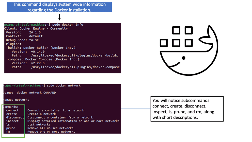
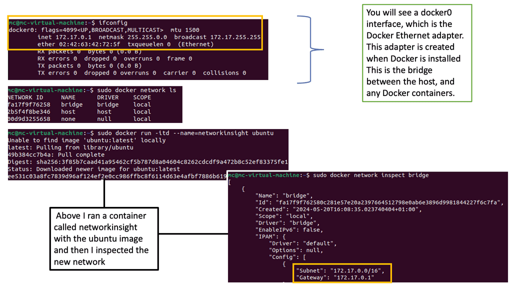
The Linux Networking Subsystem provides comprehensive tools to configure network settings. Administrators can leverage these tools to manage IP addresses, set up routing tables, configure network interfaces, apply firewall rules, and monitor network traffic. Some of the commonly used tools include ifconfig, ip, route, firewall-cmd, and tcpdump.

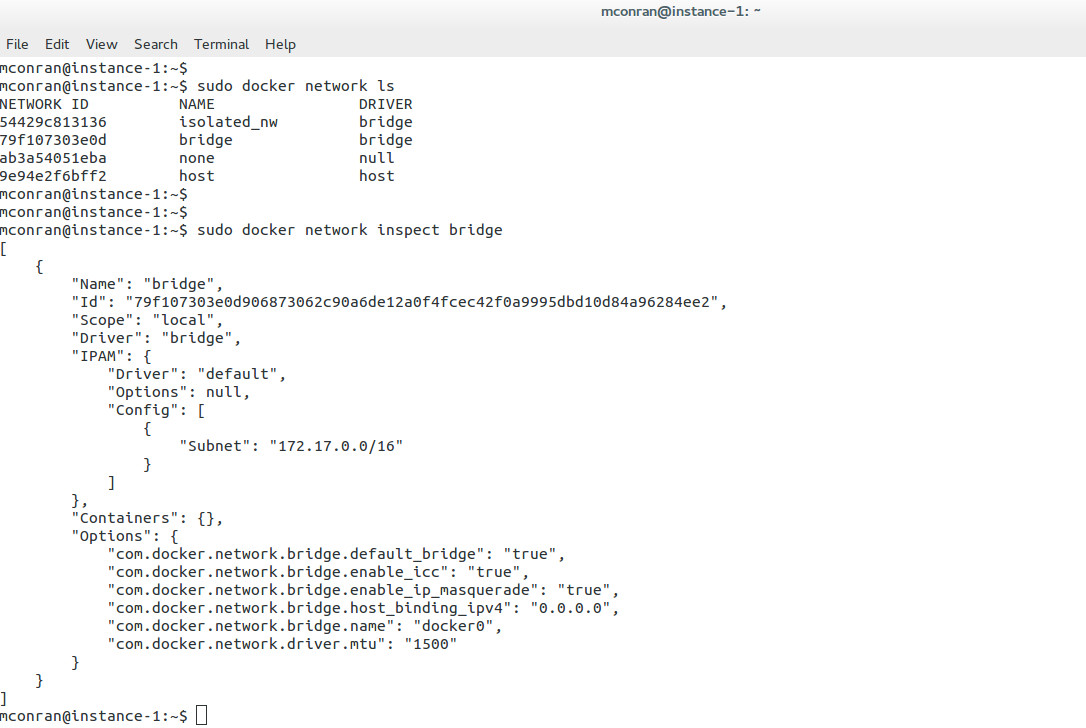
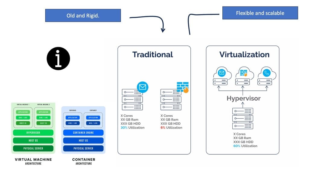
3. Network Virtualization:

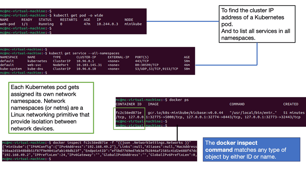
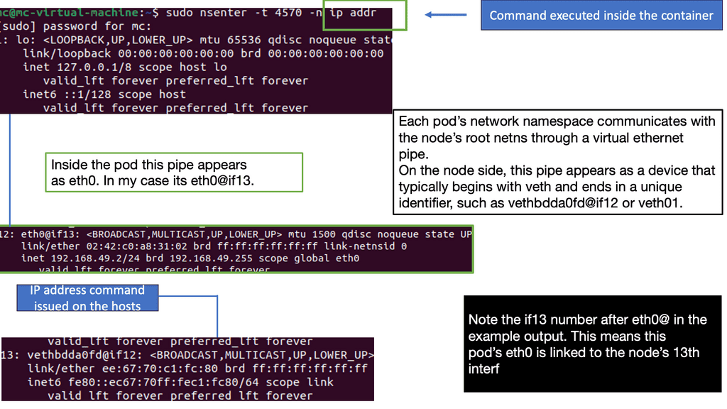
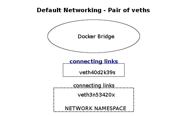
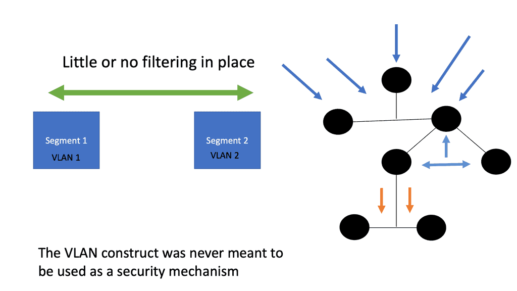
Virtualization has become an integral part of modern IT infrastructure. With its robust networking subsystem, Linux offers excellent network virtualization support. Technologies like Virtual LAN (VLAN), Virtual Extensible LAN (VXLAN), and Network Namespaces enable the creation of isolated network environments, allowing multiple virtual networks to coexist on a single physical infrastructure.

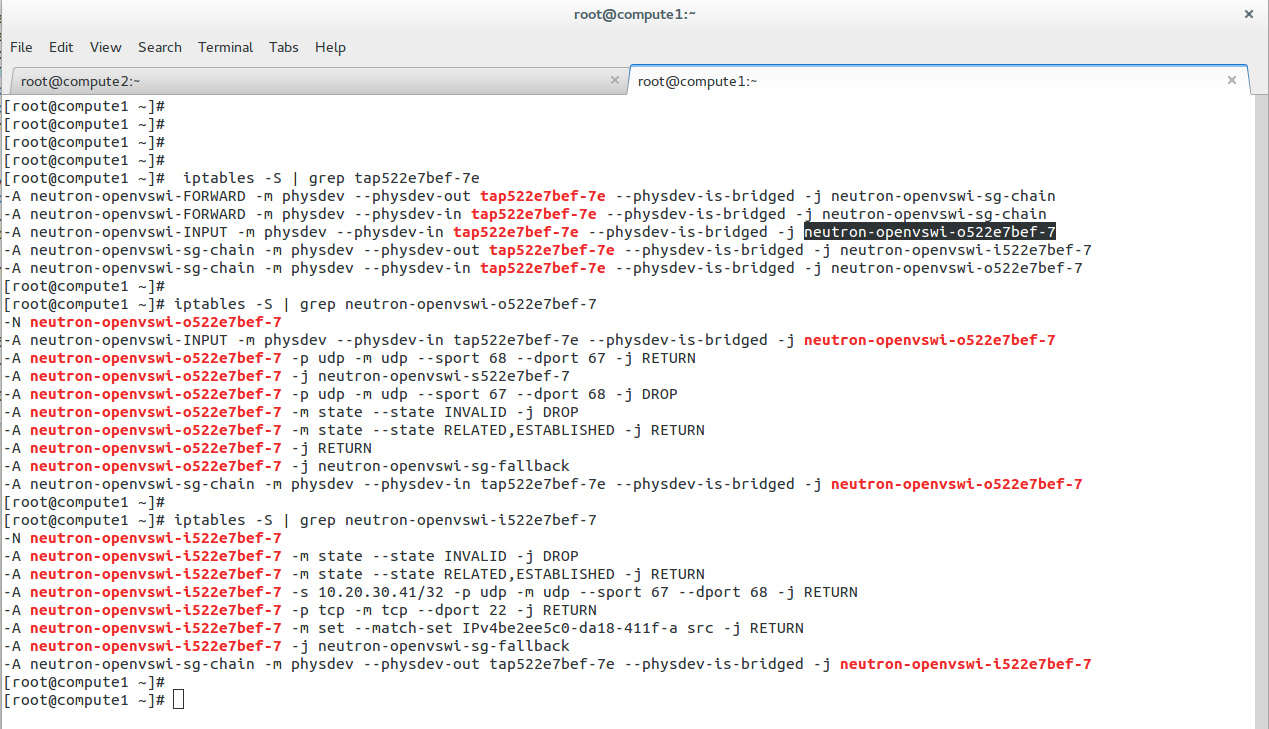
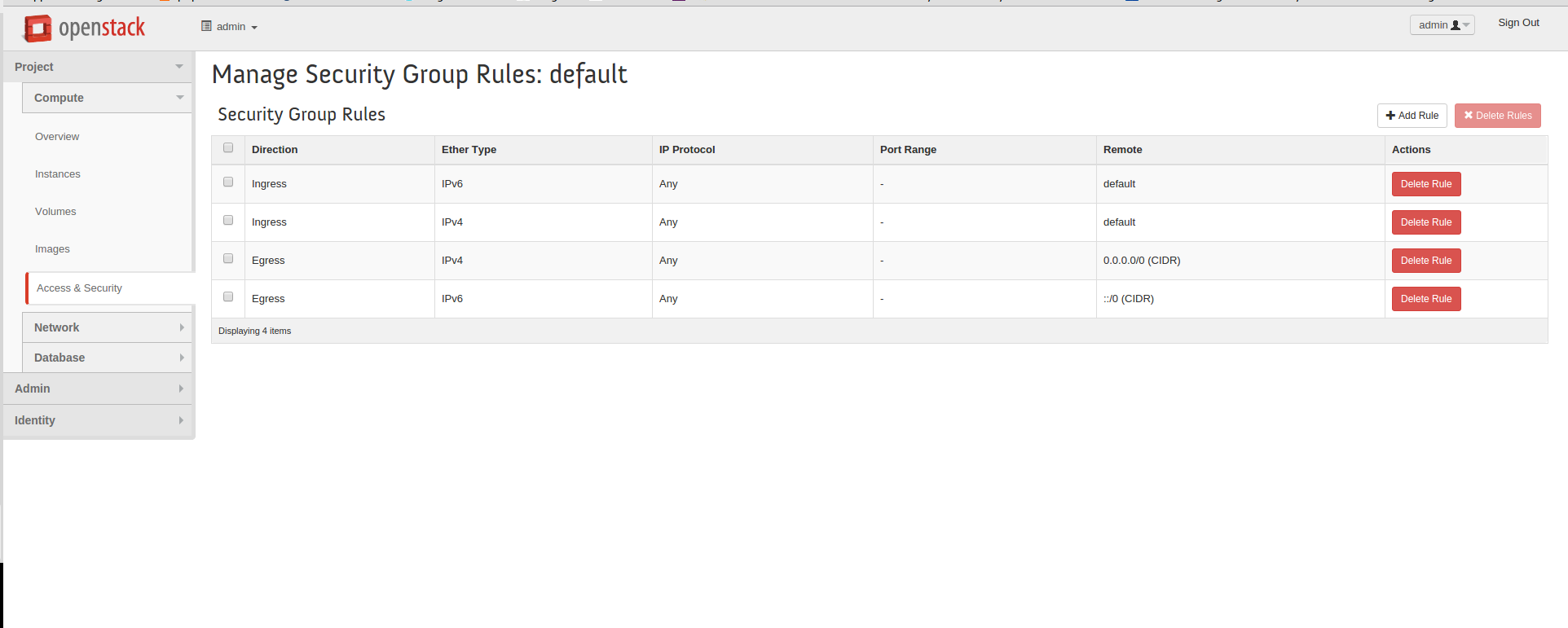
4. Packet Filtering and Firewalling:

The Linux Networking Subsystem incorporates Netfilter, a powerful packet-filtering framework. Netfilter enables administrators to implement firewall rules, perform network address translation (NAT), and control traffic flow. Coupled with tools like iptables and nftables, Netfilter empowers administrators with fine-grained control over network security and access control.

5. Network Monitoring and Troubleshooting:

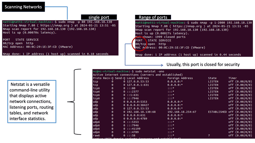
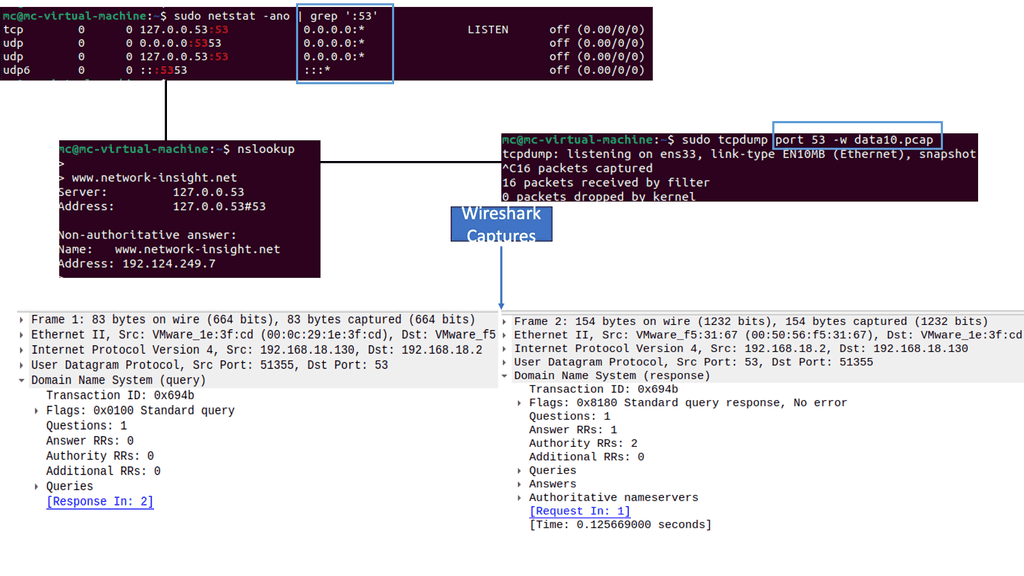
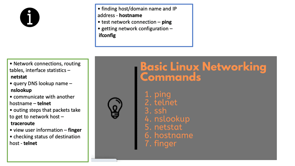
With Linux’s Networking Subsystem, network administrators have various tools to monitor and troubleshoot network-related issues. Tools like tcpdump, Wireshark, netstat, and ping enable administrators to capture and analyze network packets, monitor network connections, diagnose network problems, and measure network performance.


Highlighting Linux Networking

Linux is a powerful and versatile operating system, capable of powering a wide range of devices, from the smallest Raspberry Pi to the largest supercomputers. It is also well-respected for its networking capabilities. Linux networking technologies provide users with a secure, reliable, and fast way to connect to the Internet and other devices on the same network.

Linux supports several popular networking protocols, such as TCP/IP, IPv4, IPv6, and the latest wireless technologies. Linux also supports a wide range of networking hardware, from Ethernet cards to wireless routers. With the help of these networking technologies, users can easily connect to the Internet, share files and printers, and access networked resources from other computers.

Linux provides a range of tools for managing and configuring networks. These include a range of graphical user interfaces and powerful command-line tools such as netstat and ifconfig. Network administrators can also use tools such as iptables and iproute to set up firewalls and control network access.

Linux Networking Commands
Diagram: Basic Linux Networking Commands. The source is JavaRevisited.


  • A key point: Back to basics with Linux Firewall

Linux has almost forever had an integrated firewall available.

Linux Firewall is an essential security feature for any Linux system. It is a barrier between the outside world and the internal network, keeping malicious and unauthorized users from accessing your system. Firewalls also help protect against viruses, worms, Trojans, and other malware.

A Linux firewall is a combination of software and hardware components that together provide a secure network environment. It is designed to permit or deny network traffic based on user-defined rules. Rules can be based on various criteria, such as the source or destination IP address, type of service, or application.

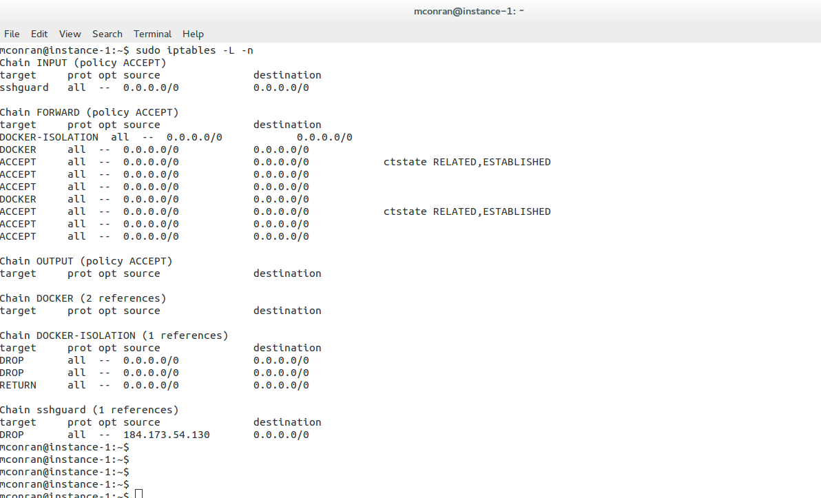
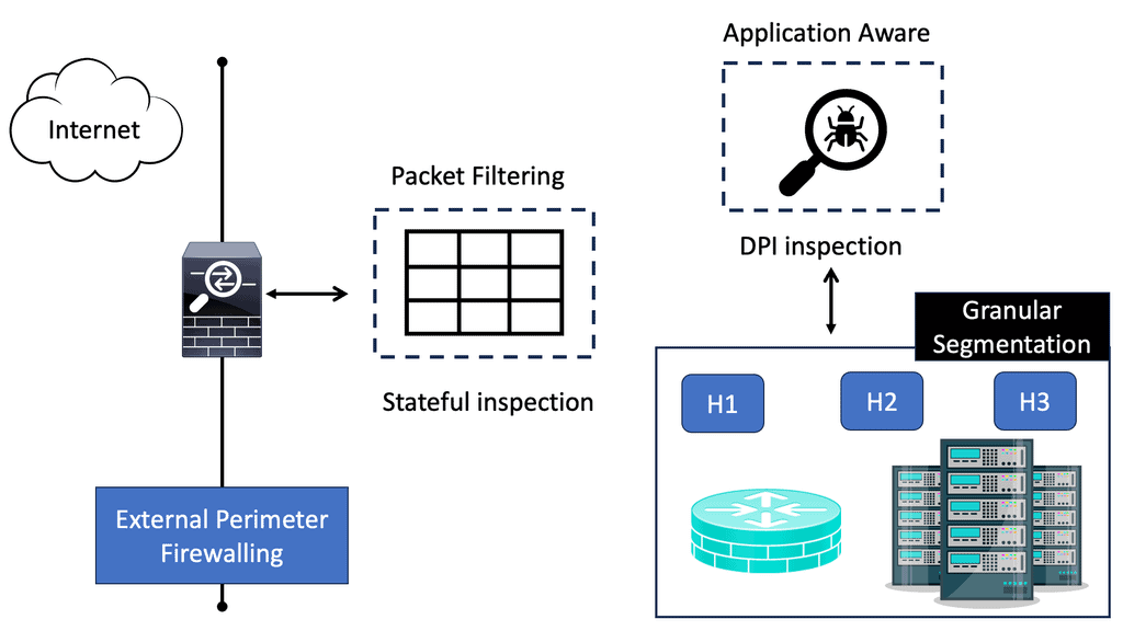
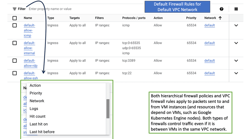
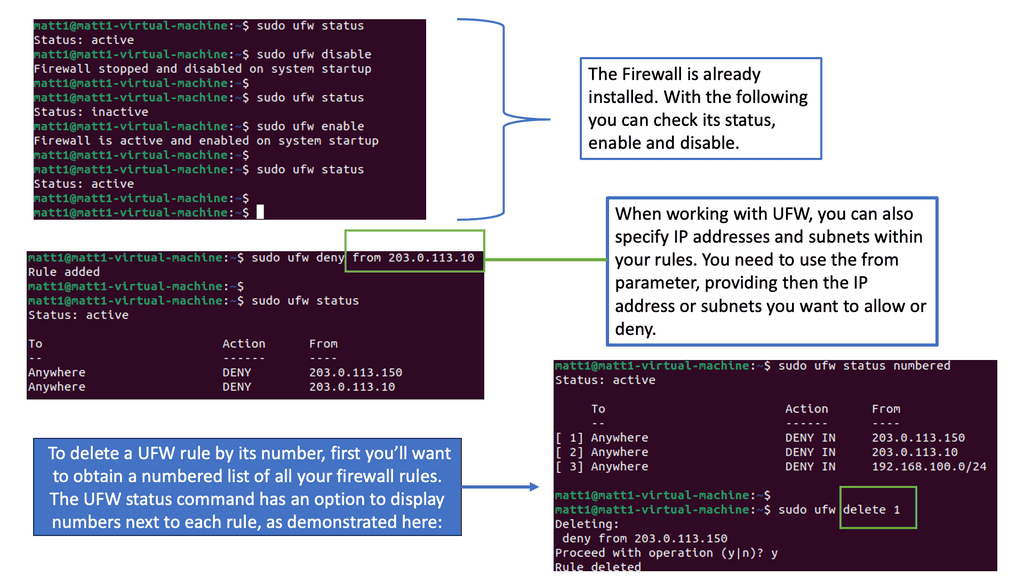
To configure a Linux firewall, you must use the iptables command. This command line utility allows you to set up rules for filtering and routing data within your network. Iptables is a powerful tool that can be used to create complex firewall rules. The following figure shows an example of a firewall that can filter requests based on protocol or target-based rules.

Linux Firewall
Diagram: Linux Firewall. Source is OpenSource.


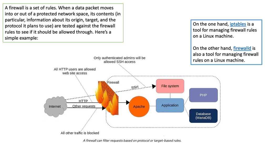
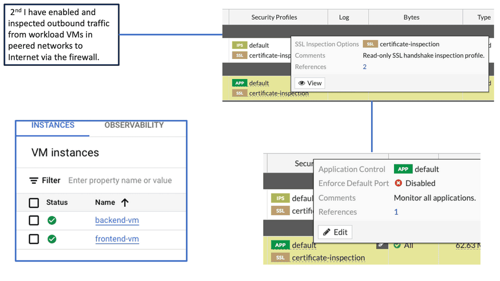
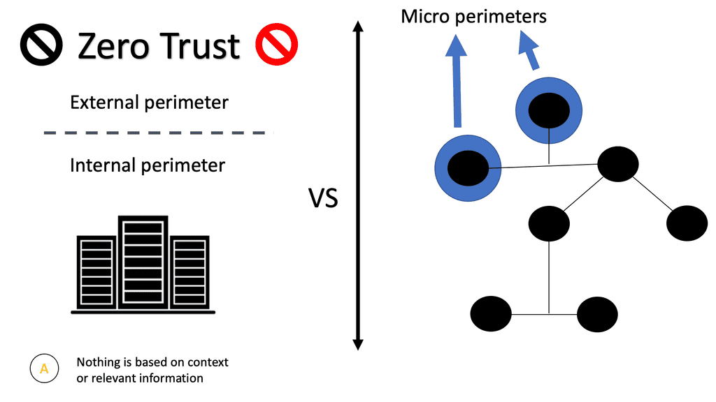
With the native firewall tools, you can prepare a traditional perimeter firewall with address translation or a proxy server. While egress filtering (outbound access controls) is recommended, this is often implemented at network perimeters – on firewalls and routers between VLANs or facing less-trusted networks such as the public internet.


Linux Network Subsystem: Netlink Linux

The Linux system architecture contains the user space, kernel, and hardware. At the top of the Linux framework, user space exists with various user applications—the kernel space forward packets in the middle, accepting instruction from the user space element.

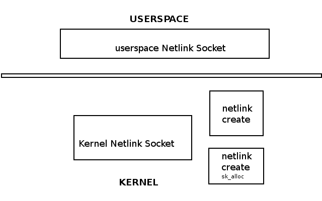
At the bottom, we have the hardware, such as CPU, RAM, and NIC. One way to communicate between userspace and kernel is via Netlink. The Linux Netlink socket is what handles bidirectional communication between the two.

It can be created in user space with the socket() system call or in the kernel with netlink_kernel_create(). For example, the following shows a Netlink Linux socket created in the kernel and userspace.


Linux networking subsystem
Diagram: Linux networking subsystem


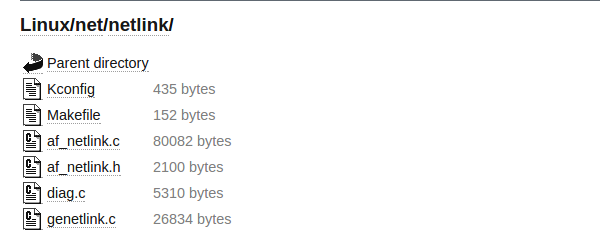
The Linux Netlink protocol implementation resides under the net/netlink folder listed below. In addition, the af_netlink provides the Netlink Linux kernel socket API, genetlink provides the generic Netlink API, and diag provides information about the Netlink sockets.


Linux Networking subsystem


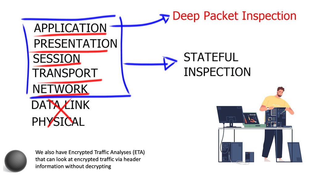
The Linux networking subsystem is part of the kernel space and is one of the most critical subsystems. Even if hosts are not connected, the network subsystem is used for the client-server interaction of X-Windows. The Linux Kernel networking stack processes incoming packets from Layer 2 to the network layer.

It then passes for local delivery to the transport layer protocols listening to TCP or UDP sockets. Any packets not destined for the local system are sent back down the stack for transmission. The kernel does not handle anything above Layer 4. Userspace applications handle all layers above Layer 4. 


  • A key point: The sk_buff and net_device

The sk_buff and net_device are fundamental to the networking subsystem. The network device driver ( net_device structure ) receives and transmits packets to pass them up the stack ( Layer 3 to Layer 4 ) or transmit them to an outgoing interface. The routing subsystem looks up every incoming/outgoing packet to determine the interface and specific packet handling activities.

Many things may affect packet traversal, such as Netfilter hooks, IPsec subsystem, TTL, etc. The sk_buff ( Socket Buffer ) represents data and headers. Packets are received on the wire by a NIC (netdevice), placed in the sk_buff, and passed through the network stack.

The userspace networking stack can slow down the performance of the CPU. Everything that crosses over to the kernel affects performance. So, if the application crosses over the user/kernel boundary, it will cost a lot.

It would help if you minimized this by keeping as much in the kernel and below as possible and only going to userspace for a quick breath. For example, transit traffic might not need to go to userspace constantly.


Linux Networking and Android

Linux is used extensively as the base for Android phones. The Linux networking stack has different needs for mobile devices than for data center devices. The phone moves continuously, connecting to different networks of varying quality. Phones are connected to multiple networking nearly all the time.

If devices are on the WIFI network and require sending an SMS, you must bring up the cell network on a different IP interface.


Multipath TCP

Users want all networks simultaneously, and the Linux stack must seamlessly switch across network boundaries. For this, the application has to shoot all the TCP connections so they don’t get blocked on reads they will never compete.

Usually, when you remove the IP address in Linux, the TCP connection will stay there, hoping that the IP address will return. As a result, the TCP connections are closed for every network switch.

Linux must also support different applications and socket routing, for example, connecting to a wireless printer while on the CELL network. There is also a method to let users know if they are connecting to a WIFI network that doesn’t have a backhaul connection.

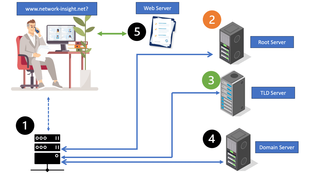
To do this, Linux must use DNS and open a TCP connection on the backhaul network. The networking stack needs to handle many functions for such a small device.


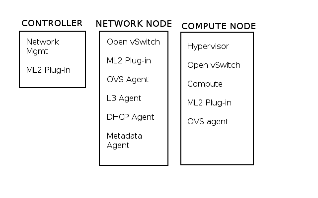
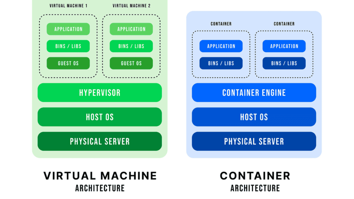
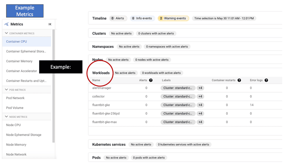
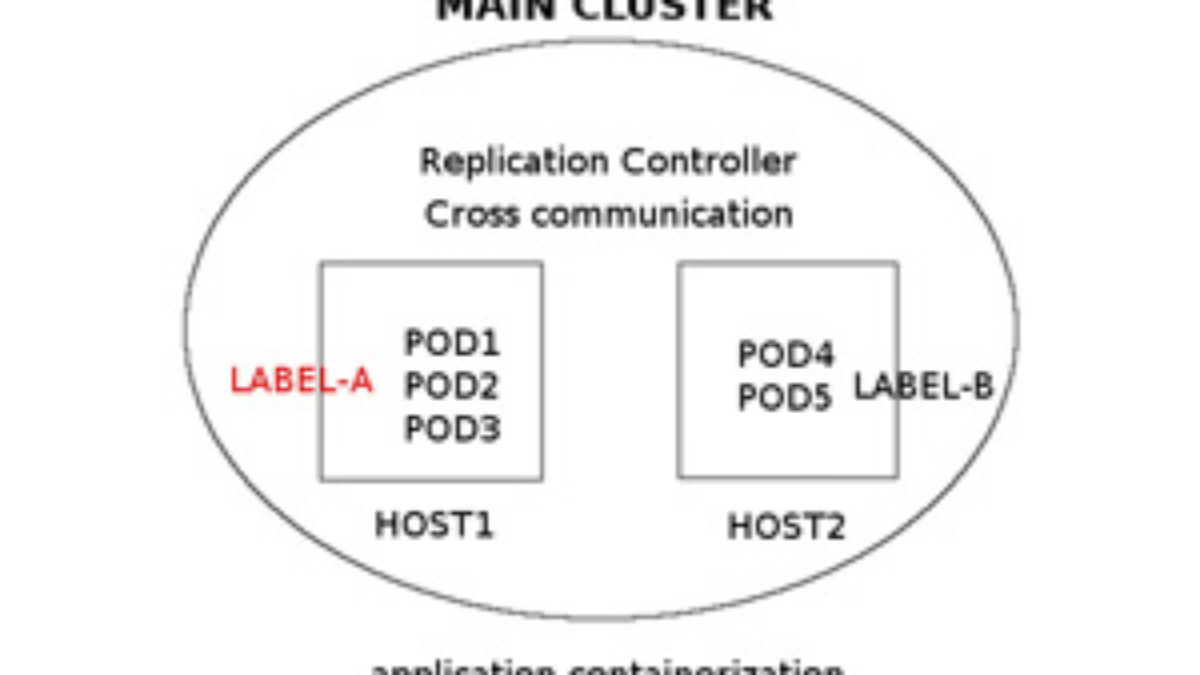
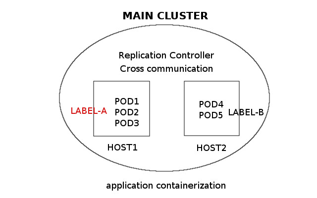
Linux Network subsystem: Linux networking and the data center

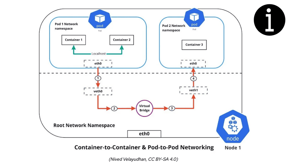
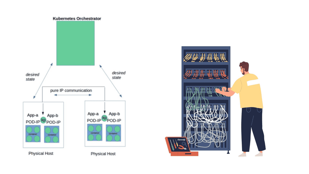
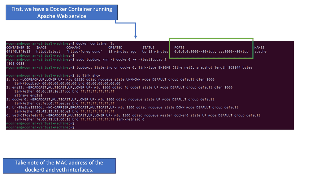
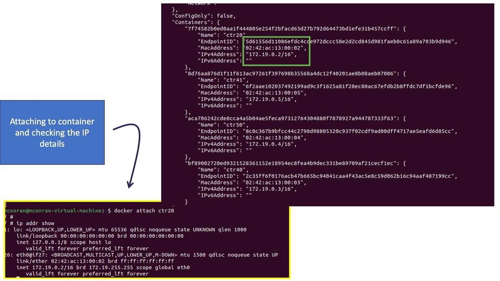
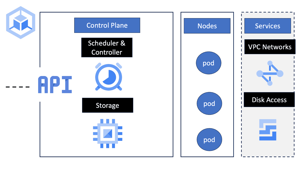
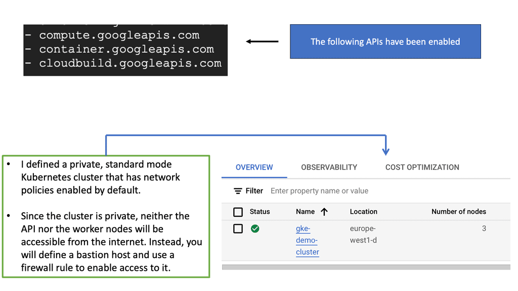
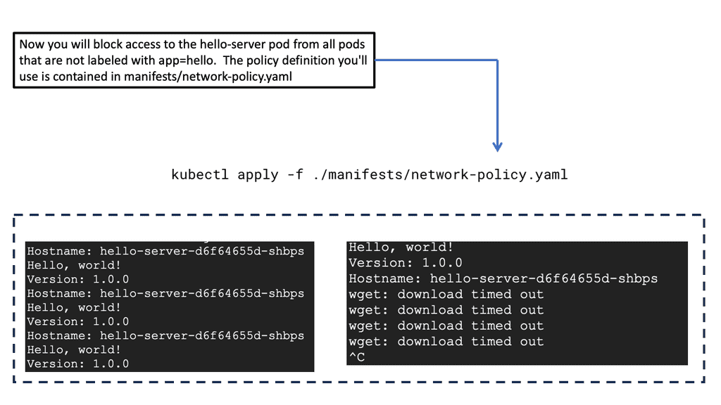
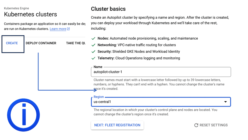
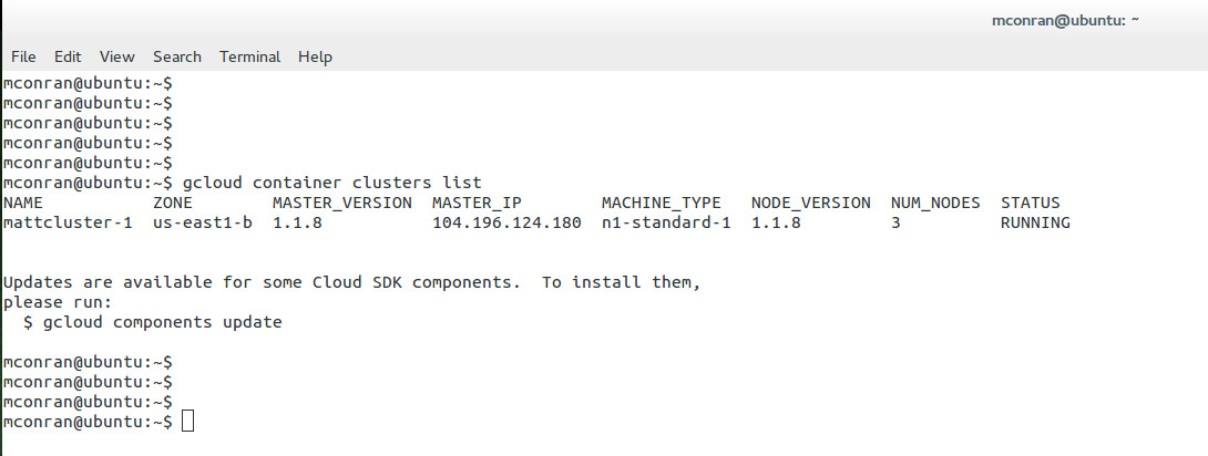
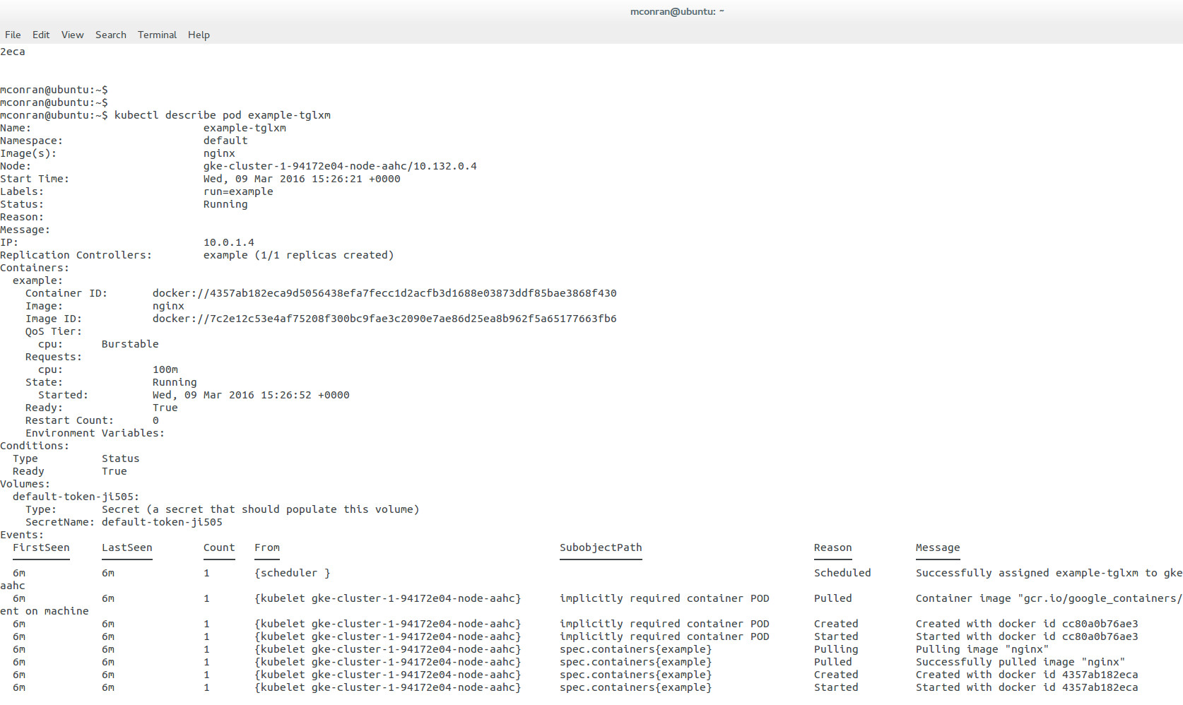
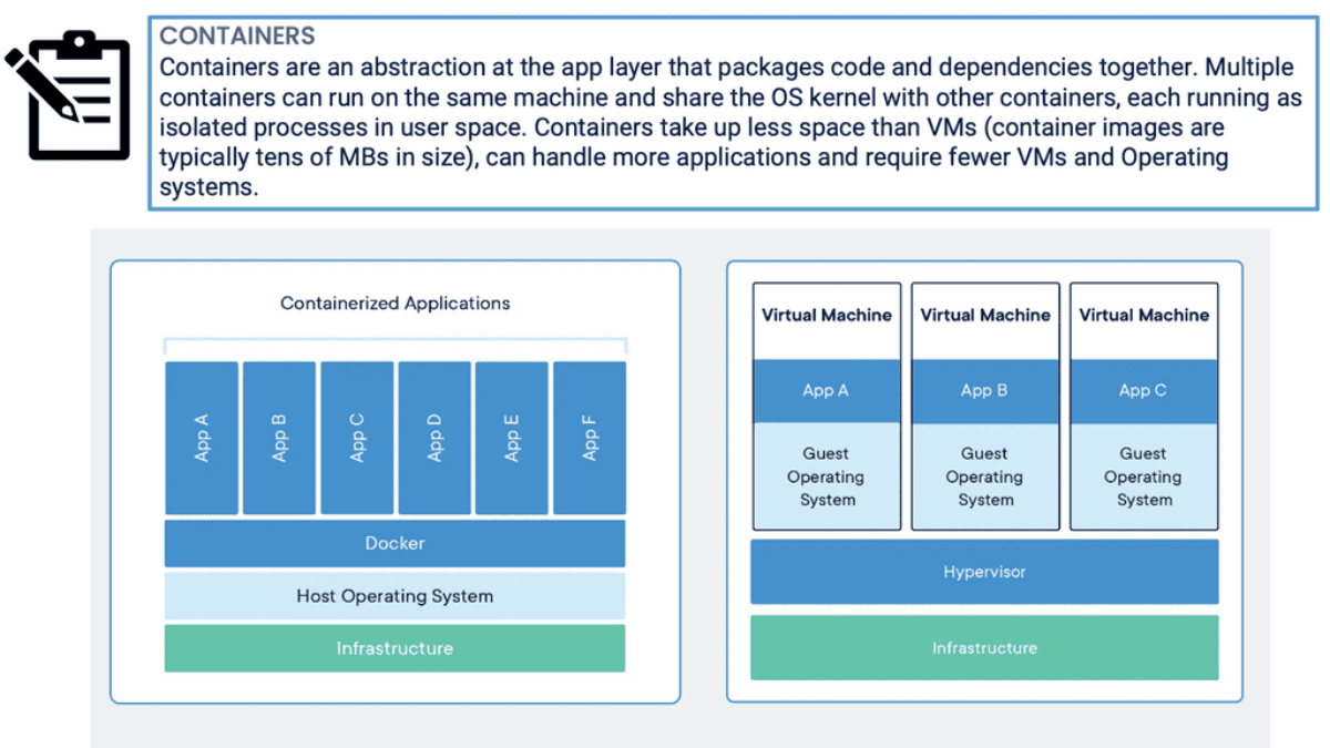
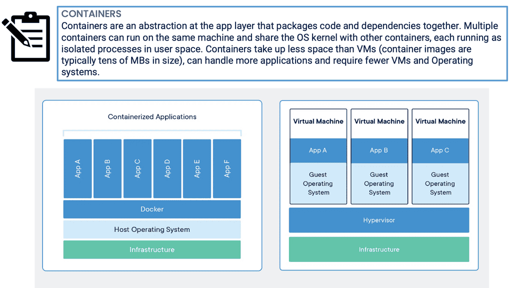
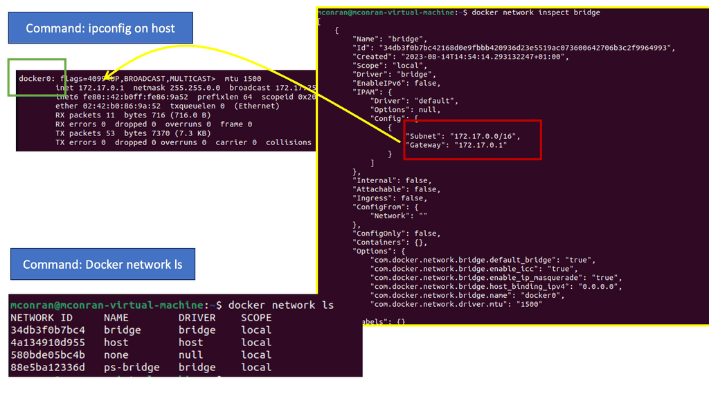
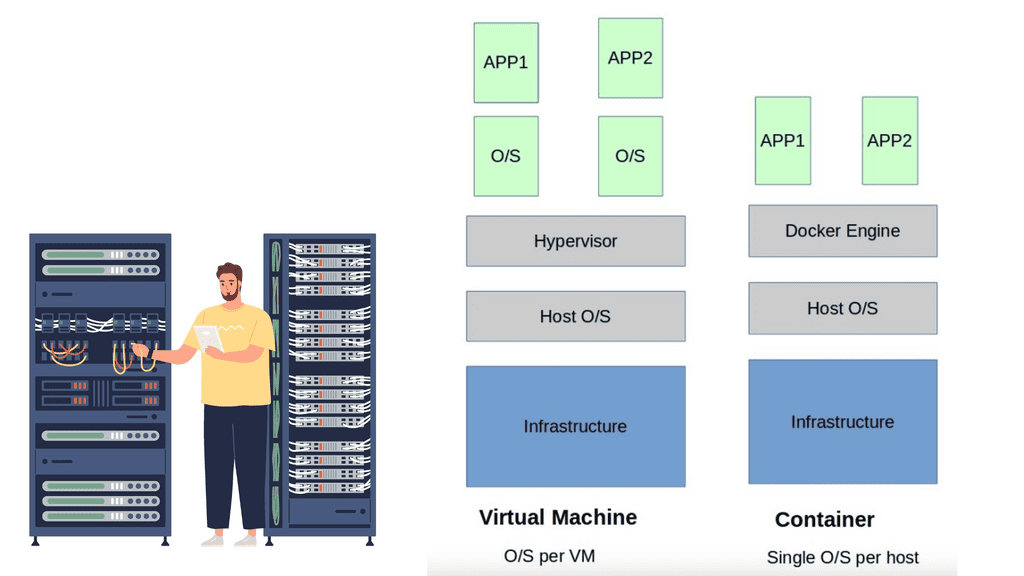
Linux has accelerated in the data center and is the base for open-source cloud environments and containerized architecture in the Kubernetes network namespace environments. Many virtual switch functions are available with hardware offload for accelerated performance.

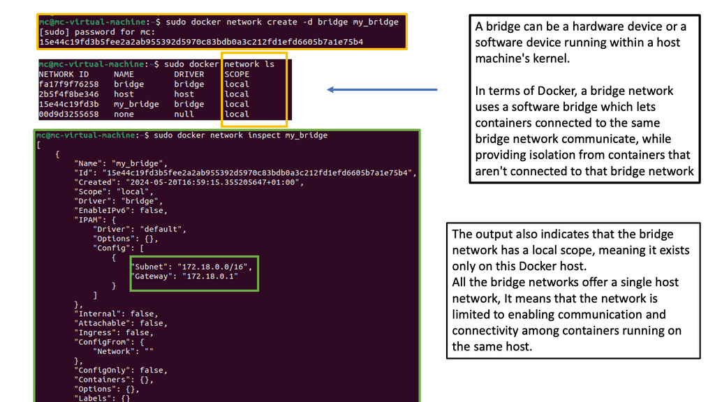
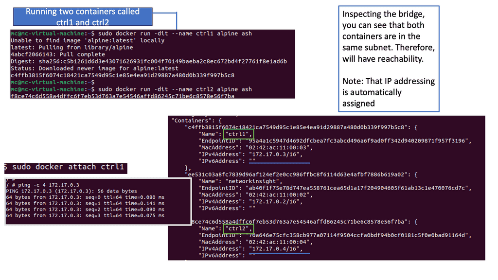
The Linux kernel supports three software bridges – Bridge, macvlan, and Open vSwitch. A NIC-embedded switch solution with SR-IOV may be used instead of the software switch. Recently, there have been many new bridge features such as FDB manipulation, VLAN filtering, Learning/flooding control, Non-promiscuous bridge, and VLAN filtering for 802.1as (Q-in-Q).

  • A typical packet processing pipeline of a switch includes:
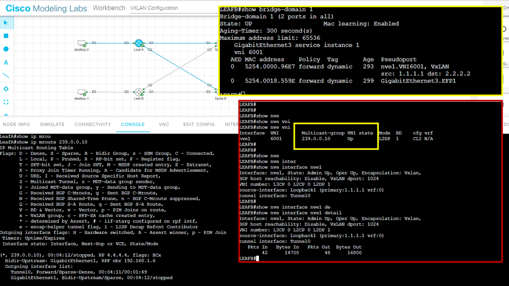
    • Packet parsing and classification – L2, L3, L4, tunneling, VXLAN VNI, inner packet L2, L3, L4.
    • Push/pop for VLAN or encapsulation/decapsulation for tunneling.
    • QoS-related functions such as Metering, Shaping, Marking, and scheduling.
    • Switching operations.

The data plane is accelerated by decomposing the packet processing pipeline and offloading some stages to the hardware ASICs. For example, layer 2 features that can be offloaded to ASIC may include MAC learning and aging, STP handling, IGMP snooping, and VLXAN. It is also possible to offload Layer 3 functions to ASICs.

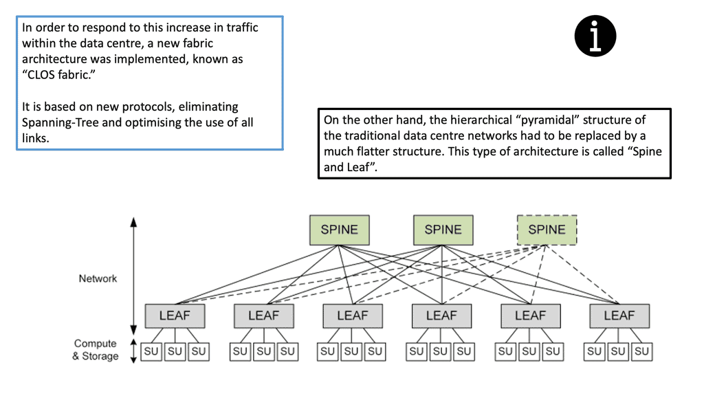
The following figure shows an example of a data center design known as the leaf and spine. Each node can run a version of Linux to perform Linux networking for the data center.

Linux networking
Diagram: Linux Networking in the data center. Source Ubuntu.


Linux switch types

The bridge is a MAC&VLAN standard bridge containing an FDB ( forwarding DB), STP ( spanning tree), and IGMP functions. The bridge contains a record of MAC to port allocation in the FDB. Building up the FDB is called “MAC learning” or simply the “learning process.” MAC VLAN is a switch based on STATIC MAC&VLAN.

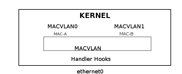
It uses unicast filtering instead of promiscuous mode and supports several modes – private, VEPA, bridge, and pass-thru. MAC VLAN is a reverse VLAN under Linux. It takes a single interface and creates multiple virtual interfaces with different MAC addresses.

Essentially, it enables the creation of independent logical devices over a single ethernet device – a “many to one” relationship in contrast to a “one to many” relationship where you map a single NIC to multiple networks. In addition, MAC VLAN offers isolation because it will only see traffic on an interface with a specified MAC address.

MACVLAN


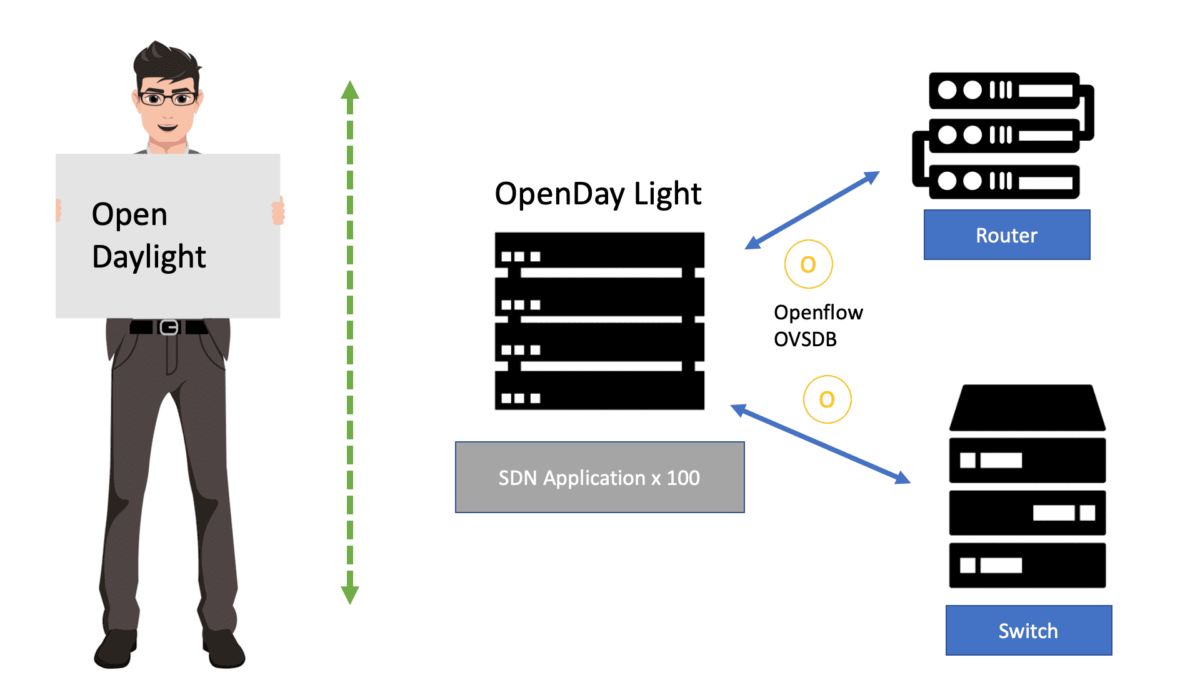
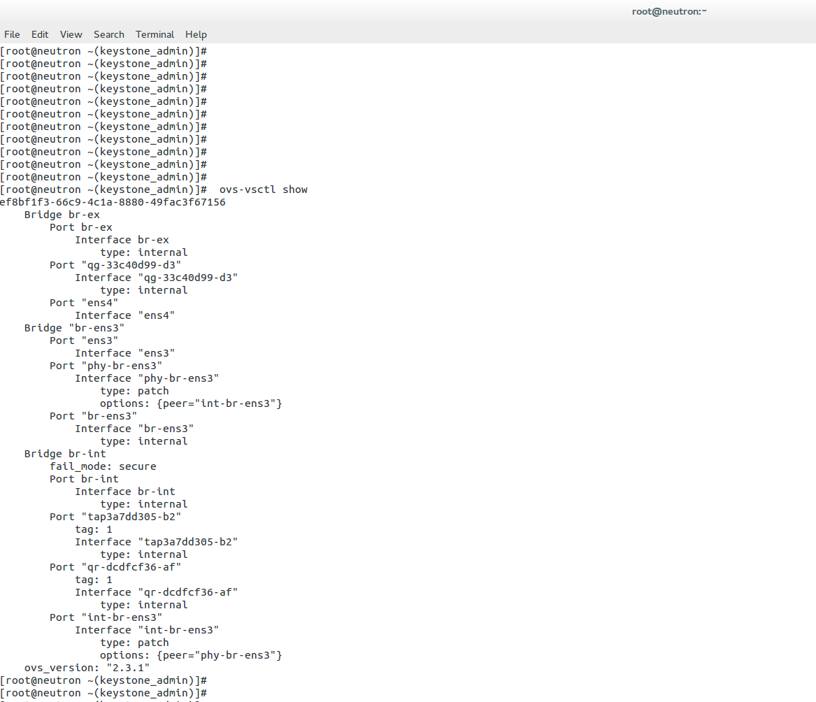
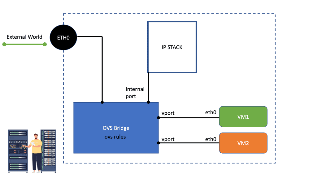
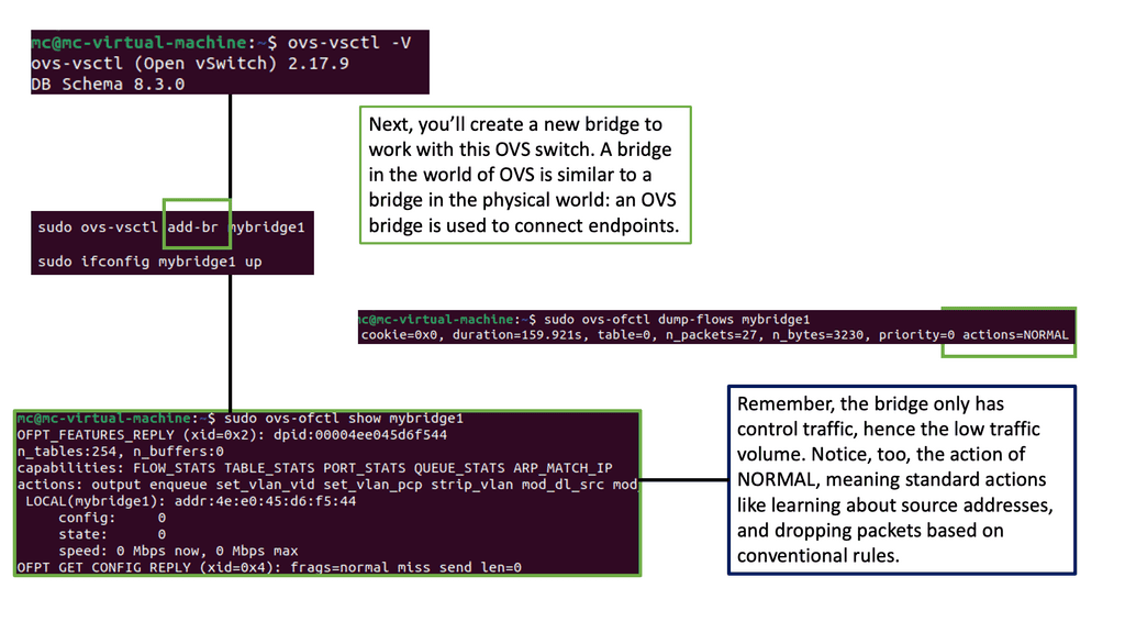
Open vSwitch is a flow-based switch that performs MAC learning like the Linux bridge enabling container networking. It supports protocols like STP and, more importantly, OpenFlow. Its forwarding is based on flows, and everything is based on a flow table. It is becoming the de facto software switch and has an impressive feature list, now including stateful services and connection tracking.

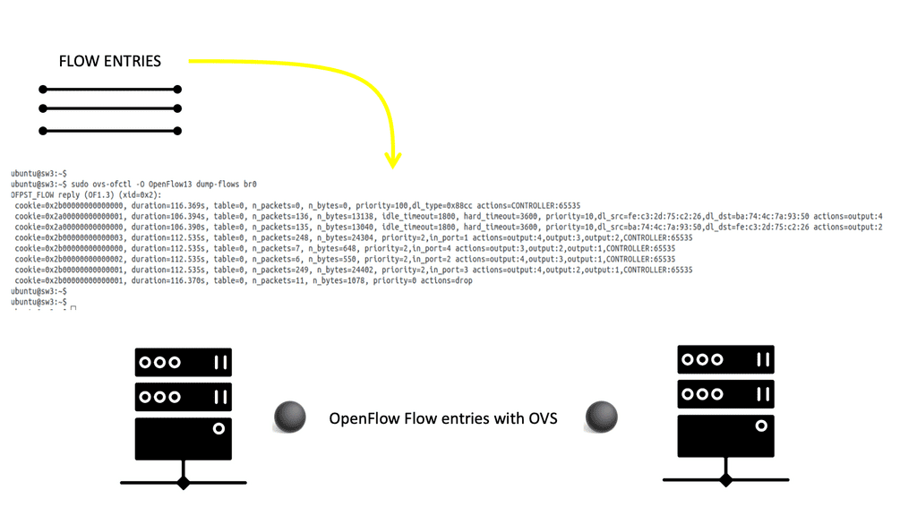
It is also used in complex cases involving nested Open vSwitch designs with OVN (Open source virtual networking). By default, the OVS acts as a learning switch and learns like a standard Layer 2 switch. For advanced operations, it can be connected to an SDN controller or use the command line to add OpenFlow rules manually.

Conclusion:

The Linux Networking Subsystem is a critical component that underpins the networking capabilities of Linux-based systems. Its robust architecture, comprehensive toolset, and support for virtualization make it a preferred choice for network administrators. By delving into the core components, network configuration, virtualization, packet filtering, and network monitoring, we have gained a deeper understanding of the Linux Networking Subsystem’s significance and its role in enabling efficient networking in Linux environments.


linux networking subsystem

OpenDaylight (ODL)

OpenDaylight

OpenDaylight

Opendaylight, an open-source software-defined networking (SDN) controller, has revolutionized the way network infrastructure is managed. In this blog post, we will delve into the capabilities of Opendaylight and explore how it empowers organizations to optimize their network operations and unlock new possibilities.

Opendaylight, often abbreviated as ODL, is a robust and scalable SDN controller built by a vibrant community of developers. It provides a flexible platform for network management and control, enabling administrators to programmatically configure and monitor their network infrastructure. With its modular architecture and extensive set of APIs, Opendaylight offers unparalleled versatility and extensibility.

One of the standout features of Opendaylight is its comprehensive support for various southbound and northbound protocols. From OpenFlow to NETCONF and RESTCONF, Opendaylight seamlessly integrates with diverse network devices and applications, making it an ideal choice for heterogeneous environments. Additionally, its rich set of network services, such as topology discovery, traffic engineering, and load balancing, empower network administrators to optimize performance and enhance security.

Opendaylight's true power lies in its ability to be extended and customized through applications and plugins. Developers can leverage the Opendaylight platform to build innovative network management applications tailored to their organization's specific needs. Whether it's implementing advanced analytics, orchestrating complex network services, or integrating with other management systems, Opendaylight provides a solid foundation for creating cutting-edge solutions.

The strength of Opendaylight lies not only in its technology but also in its active and diverse community. With contributors ranging from industry giants to individual enthusiasts, the Opendaylight community fosters collaboration, knowledge sharing, and continuous improvement. The ecosystem surrounding Opendaylight comprises a wide array of plugins, tools, and frameworks that further enhance its capabilities and make it a vibrant and thriving platform.

Conclusion: Opendaylight has emerged as a game-changer in the field of network management, offering a flexible and powerful solution for organizations of all sizes. Its extensive features, extensibility, and vibrant community make it an ideal choice for empowering network administrators to take control of their infrastructure. By embracing Opendaylight, organizations can unlock new possibilities, enhance operational efficiency, and pave the way for future innovations in network management.

Highlights: OpenDaylight


Open-source SDN 

OpenDaylight, or ODL, is one of the most popular open-source SDN controllers. Controllers like ODL are platforms, not products. As a result of the applications on top of the controller platform, this platform can provide specialized applications, including network virtualization, network monitoring, visibility, tap aggregation, and many other functions. Controllers can offer so much more than fabrics, network virtualization, and SD-WAN because of this.

In addition to ODL, there are other open-source controllers. The Open Network Foundation offers ONOS, and ETSI offers TeraFlow. Each solution has a different focus and feature set depending on the use case.

The Role of Abstraction

What is the purpose of the service abstraction layer in the OpenDaylight SDN controller? Traditional networking involves physical boxes that are physically connected. Each device has a data and control plane function. The data plane is elementary and forwards packets as quickly as possible. The control plane acts as the point of intelligence and sets the controls necessary for data plane functionality.

SDN Controller

With the OpenDaylight SDN controller, we drag the control plane out of the box and centralize it on a standard x86 server. What happens in the data plane does not change; we still forward packets. It still consists of tables that look at packets and perform some action. What changes are the mechanisms for how and where tables get populated? All of which share similarities with the OpenStack SDN controller.

OpenDaylight

OpenDaylight is the central control panel that helps populate these tables and move data through the network as you see fit. It consists of an open API that allows the control of network objects as applications. So, to start the core answers, what is the purpose of the service abstraction layer in the OpenDaylight SDN controller? Let’s look at the OpenDaylight and OpenStack SDN controller integrations.


OpenDaylight SDN Controller.

Key OpenDaylight Discussion points:


  • Introduction to OpenDaylight SDN Controller.

  • Discussion on the OpenDaylight integrations.

  • Complications with Neutron Networking.

  • The Neutron Networking model.

  • Highlighting OpenDaylight project components.

For additional pre-information, you may find the following helpful:

  1. OpenStack Architecture


A key point: Ansible and OpenDaylight

The Ansible architecture is simple, flexible, and powerful, with a vast community behind it. Ansible is capable of automating systems, storage, and of course, networking. However, Ansible is stateless, and a stateful view of the network topology is needed from the network engineer’s standpoint. This is where OpenDaylight joins the game.

As an open-source SDN controller and network platform, OpenDaylight translates business APIs into resource APIs, and Ansible networking performs its magic in the network. The Ansible architecture, specifically the Ansible Galaxy tool that ships with Ansible, can be used to install OpenDaylight. To install OpenDaylight on your system, you can use an Ansible playbook.

Back To Basics With OpenDaylight

OpenDaylight Integration: OpenStack SDN Controller

The single API is used to configure heterogeneous hardware. OpenDaylight integrates tightly with the OpenStack SDN controller, providing the central controller element for many open-source clouds. It was born shortly after Neutron, and the two projects married as soon as the ML2 plugin was available in Neutron. OpenDaylight is not intended to replace the Neutron Networks but adds and provides better functionality and network management. OpenDaylight Beryllium offers a Base, Virtualized, and Service Provider edition.

OpenDaylight (ODL) understands the network at a high level, running multiple applications on top of managing network objects. It consists of a Northbound interface, Middle tier, and Southbound interface. The northbound interface offers the network’s abstraction. It exposes interfaces to those writing applications to the controller, and it’s here that you make requests with high-level instructions.

The middle tier interprets and compiles the request, enabling the southbound interface to action the network. The type of southbound protocol is irrelevant to the northbound API. It’s wholly abstracted and could be OpenFlow, OVSDB, or BGP-LS. The following screen displays generic information for the OpenDaylight Lithium release.

What is the purpose of the service abstraction layer in the open daylight sdn controller

Key Features and Capabilities:

1. OpenDaylight Controller: At the core of OpenDaylight is its controller, which acts as the brain of the network. The controller provides a centralized network view, enabling administrators to manage resources, define network policies, and dynamically adapt to changing network conditions.

2. Northbound and Southbound Interfaces: OpenDaylight offers northbound and southbound interfaces that facilitate communication between the controller and network devices. The northbound interface enables applications and services to interact with the controller, while the southbound interface allows the controller to communicate with network devices, such as switches and routers.

3. Modular Architecture: OpenDaylight’s modular architecture provides flexibility and extensibility. It allows developers to add or remove modules based on specific network requirements, ensuring the platform remains lightweight and adaptable to various network environments.

4. Comprehensive Set of Protocols: OpenDaylight supports various industry-standard protocols, including OpenFlow, NETCONF, and BGP. This compatibility ensures seamless integration with existing network infrastructure, making adopting OpenDaylight in diverse network environments easier.

Benefits of OpenDaylight:

1. Network Automation: OpenDaylight simplifies network management by automating repetitive tasks like provisioning and configuration. This automation significantly reduces the time and effort required to manage complex networks, allowing network engineers to focus on more strategic initiatives.

2. Enhanced Network Visibility: With its centralized control and management capabilities, OpenDaylight provides real-time visibility into network performance and traffic patterns. This visibility allows administrators to promptly identify and troubleshoot network issues, improving reliability and performance.

3. Scalability and Flexibility: OpenDaylight’s modular architecture and support for industry-standard protocols enable seamless scalability and flexibility. Network administrators can quickly scale their networks to accommodate growing demands and integrate new technologies without disrupting existing infrastructure.

4. Innovation and Collaboration: Being an open-source platform, OpenDaylight encourages collaboration and innovation within the networking community. Developers can contribute to the project, share ideas, and leverage their collective expertise to build cutting-edge solutions that address evolving network challenges.

Complications with Neutron Network

Initially, OpenStack networking was built into Nova ( nova-network ) and offered little network flexibility. It was rigid and significant if you only wanted a flat Layer 2 network. Flat networks are fine for small designs with single application environments, but anything at scale will reach CAM table limits. VLANs also have theoretical hard stops.

Nova networking was represented as a second-class citizen in the compute stack. Even OpenStack Neutron Security Groups were dragged to another device and not implemented at a hypervisor level. This was later resolved by putting IPtables in the hypervisor, but we still needed to be on the same layer 2 domain.

Limitation of Nova networking

Nova networking represented limited network functionality and did not allow tenants to have advanced control over network topologies. There was no load balancing, firewalling, or support for multi-tenancy with VXLAN. These were some pretty big blocking points.

Suppose you had application-specific requirements, such as a vendor-specific firewall or load balancer, and you wanted OpenStack to be the cloud management platform. In that case, you couldn’t do this with Nova. OpenStack Neutron solves all these challenges with its decoupled Layer 3 model.

A key point: Networking with Neutron

Networking with Neutron offers better network functionality. It provides an API allowing the interaction of network constructs ( router, ports, and networks ), enabling advanced network functionality with features such as DVR, VLXAN, Lbass, and FWass.

It is pluggable, enabling integration with proprietary and open-source vendors. Neutron offers more power and choices for OpenStack networking, but it’s just a tenant-facing cloud API. It does not provide a complete network management experience or SDN controller capability.

The Neutron networking model

The Neutron networking model consists of several agents and databases. The neutron server receives API calls and sends the message to the Message Queue to reach one of the agents. Agents on each compute node are local, actioning, and managing the flow table. They are the ones that carry out the orders.

The Neutron server receives a response from the agents and records the new network state in the database. Everything connects to the integration bridge ( br-int ), where traffic is tagged with VLAN ID and handed off to the other bridges, such as br-tun, for tunneling traffic.

Each network/router uses a Linux namespace for isolation and overlapping IP addresses. The complex architecture comprises many agents on all compute, network, and controller nodes. It has scaling and robustness issues you will only notice when your system goes down.

Neutron is not an API for managing your network. If something is not working, you need to check many components individually. There is no specific way to look at the network in its entirety. This would be the job of an OpenDaylight SDN controller or an OpenStack SDN controller.

OpenDaylight Project Components

OpenDaylight is used in conjunction with Neutron. It represents the controller that sits on top and offers abstraction to the user. It bridges the gap between the user’s instructions and the actions on the compute nodes, providing the layer that handles all the complexities. The Neutron doesn’t go away and works together with the controller.

Neutron gets an ODL driver installed that communicates with a Northbound interface that sits on the controller. The MD-SAL (inventory YANG model) in the controller acts as the heart and communicates to both the controller OpenFlow and OVSDB components.

OpenFlow and OVSDB are the southbound protocols that configure and program local compute nodes. The OpenDaylight OVSDB project is the network virtualization project for OpenStack. The following displays OpenvSwtich connection to OpenDaylight. Notice the connection status is “true.” For this setup, the controller and switch are on the same node.

opendaylight sdn controller
Diagram: Opendaylight sdn controller and OpenvSwtich connection.

The role of OpenvSwitch

OpenvSwitch is viewed as the workhorse forOpenDaylight. It is programmable and offers advanced features such as NetFlow, sFlow, IPFIX, and mirroring. It has extensive flow matching capabilities – Layer 1 ( QoS priority, Tunnel ID), Layer 2 ( MAC, VLAN ID, Ethernet type), Layer 3 (IPv4/v6 fields, ARP), Layer 4 ( TCP/UDP, ICMP, ND) with many chains of action such as output to port, discard and packet modification. The two main userspace components are the ovsdb-server and the ovs-vswitchd.

The ODL OVSDB manager interacts with the ovsdb-server, and the ODL OpenFlow controller interacts with the ovs-vswitchd process. The OVSDB southbound plugin plugs into the ovsdb-server. All the configuration of OpenvSwitch is done with OVSDB, and all the flow adding/removing is done with OpenFlow.

OpenDaylight OpenFlow forwarding

OpenStack traditional Layer 2 and Layer 3 agents use Linux namespaces. The entire separation functionality is based on namespaces. OpenDaylight doesn’t use namespaces; you only have a namespace for the DHCP agent. It also does not have a router or operate with a network stack—the following displays flow entries for br0. OpenFlow ver1.3 is in use.

Openvswitch bridge

OpenFlow rules are implemented to do the same job as a router. For example, MAC is changing or TTL decrementation. ODL can be used to manipulate packets, and the Service Function Chain (SFC) feature is available for advanced forwarding. Then, you can use service function chaining with service classifier and service path for path manipulation.

OpenDaylight service chaining has several components. The job of the Service Function Forwarder (SFF) is to get the flow to the service appliance; this can be accomplished with a Network Service Header (NSH) or using some tunnel with GRE or VXLAN.

OpenDaylight has emerged as a powerful platform for network automation and SDN, empowering organizations to unlock their networks’ full potential. Its robust features, modular architecture, and support for industry-standard protocols make it a valuable asset for network administrators and developers. By embracing OpenDaylight, organizations can streamline their network management processes, enhance network visibility, and foster innovation. As the networking landscape continues to evolve, OpenDaylight will undoubtedly play a vital role in shaping the future of network automation and software-defined networking.


Summary: OpenDaylight

OpenDaylight is a powerful open-source platform that revolutionizes software-defined networking (SDN) by providing a flexible and scalable framework. In this blog post, we will explore the various components of OpenDaylight and how they contribute to SDN’s success.

OpenDaylight Controller

The OpenDaylight controller is the platform’s core component, acting as the central brain that orchestrates network functions. It provides a robust and reliable control plane, enabling seamless communication between network devices and applications.

OpenFlow Plugin

The OpenFlow Plugin is a critical component of OpenDaylight that enables communication with network devices supporting the OpenFlow protocol. It allows for the efficient provisioning and management of network flows, ensuring dynamic control and optimization of network traffic.

YANG Tools

YANG Tools play a pivotal role in OpenDaylight by facilitating the modeling and management of network resources. With YANG, network administrators can define the data models for network elements, making it easier to configure, monitor, and manage the overall SDN infrastructure.

Network Applications

OpenDaylight offers a rich ecosystem of network applications that leverage the platform’s capabilities. These applications range from network monitoring and security to load balancing and traffic engineering. They empower network administrators to customize and extend the functionality of their SDN deployments.

Southbound and Northbound APIs

OpenDaylight provides a set of southbound and northbound APIs that enable seamless integration with network devices and external applications. The southbound APIs, such as OpenFlow and NETCONF, facilitate communication with network devices. In contrast, the northbound APIs allow external applications to interact with the OpenDaylight controller, enabling the development of innovative network services.

Conclusion:

OpenDaylight’s components work harmoniously to empower software-defined networking, offering unprecedented flexibility, scalability, and control. From the controller to the network applications, each component is crucial in enabling efficient network management and driving network innovation.

In conclusion, OpenDaylight catalyzes the transformation of traditional networks into intelligent and dynamic infrastructures. By embracing the power of OpenDaylight, organizations can unlock the true potential of software-defined networking and pave the way for a more agile and responsive network ecosystem.

Male informatic engineer working inside server room database

OpenStack Neutron

OpenStack Neutron

OpenStack Neutron is a powerful networking service that has revolutionized the world of network virtualization. In this blog post, we will delve into the intricacies of OpenStack Neutron and explore its key features and capabilities.

OpenStack Neutron is an integral part of the OpenStack ecosystem, providing a flexible and scalable networking platform for cloud-based applications. It enables users to create and manage networks, subnets, routers, and security groups, offering a comprehensive set of networking services.

One of the standout features of OpenStack Neutron is its support for multi-tenancy. It allows users to create isolated network environments, ensuring secure communication and resource isolation. Additionally, Neutron provides a rich set of APIs for programmatic management, making it highly customizable and adaptable to various network architectures.

OpenStack Neutron enables network virtualization by abstracting the underlying physical infrastructure and providing a virtual networking layer. This allows for efficient resource utilization and seamless scaling of network resources. With Neutron, users can create virtual networks with different topologies, connect them with routers, and define advanced networking policies.

OpenStack Neutron seamlessly integrates with Software-Defined Networking (SDN) technologies, such as OpenFlow and OVS (Open vSwitch). This integration enhances network programmability and enables advanced networking capabilities, such as traffic steering, QoS (Quality of Service), and network slicing.

OpenStack Neutron has transformed the way we approach network virtualization, offering a powerful and flexible networking solution for cloud-based applications. Its rich feature set, seamless integration with SDN technologies, and support for multi-tenancy make it a game-changer in the world of network virtualization.

In conclusion, OpenStack Neutron empowers organizations to build robust and scalable networks, enabling them to leverage the full potential of cloud computing. Whether you are a cloud service provider or an enterprise looking to optimize your network infrastructure, OpenStack Neutron provides the tools and capabilities to meet your networking needs.

Highlights: OpenStack Neutron

The role of segregation

In the cloud infrastructure, networking is one of the core services. It must provide connectivity to virtual instances while segregating traffic from different tenants and preventing cross-talk between them. Networking in OpenStack is self-service. As a result, tenants can design their networks, manage multiple network topologies, link networks together, access external networks, and deploy advanced networking services. Cloud instances are exposed to the external world via networking services, so deploying access control is imperative. As a result of OpenStack networking, firewalls can be created, and tenants can control how their networks are accessed finely.

Virtual machine instances in the Nova project were historically connected by using:

  1. A flat network comprises a single IP pool and a Layer-2 domain shared by all cloud tenants.
  2. This type of network separates traffic using VLAN tags. VLAN configuration is required on Layer-2 devices (switches).

Nova still provides these basic networking features; however, Neutron’s OpenStack networking project provides all advanced networking features.

Neutron Features

With its overwhelming features and capabilities, Neutron has become an increasingly effective and robust network project in the OpenStack ecosystem. In addition to networks, subnets, routers, load balancers, firewalls, and ports, it allows operators to build and manage a complete network topology.

Neutron’s API server receives all networking service requests. For scalability and availability, multiple instances of the API server can be deployed on the OpenStack controller node:

  • The architecture of Neutron is based on plugins. Neutron plugins provide additional network services.
  • Once the API server receives a new request, it is forwarded to a specific plugin, depending on Neutron’s configuration. A Neutron plugin orchestrates the physical resources to instantiate the requested networking feature on the controller node. Resources can be orchestrated directly through a Neutron plugin or via agents:
  • The Neutron project provides an open-source implementation of plugins and agents based on OpenStack technologies. An agent can be deployed on a compute node or a network node. Routing, firewalling, load balancing, and VPN services are implemented on network nodes.
  • Vendors can implement their plugins and support networking gear by implementing well-defined APIs.

Components Involved

OpenStack Networking with OpenStack Neutron consists of several agents/components. The central entity is the neutron-server daemon, aka the Neutron Server. It consists of a REST service and a Neutron plugin. Plugins essentially enable additional network capability. The Neutron Agent is what the Neutron server communicates with over the message bus.

The Neutron server may well act as the network’s brain, but the agents on the Compute and Network nodes carry out the changes. OpenStack Neutron agents include the L2 agent, L3 agent, and DHCP agent. 


OpenStack Neutron.

Key OpenStack Neutron Discussion points:


  • Introduction to Networking with Neutron.

  • Discussion on the ports, subnets and networks.

  • VM connectivity.

  • The Open vSwitch agent.

For additional pre-information, you may find the following helpful

  1. Neutron Network
  2. OpenStack Architecture
  3. OpenDaylight
  4. OpenShift SDN
  5. OpenFlow Protocol

Back To Basics With OpenStack Neutron

OpenStack Networking, or Neutron, delivers a network infrastructure-as-a-service platform to cloud users. Neutron constructs the virtual network using features familiar to most system and network administrators, including networks, subnets, ports, routers, and load balancers.

Now, you can configure network topologies by creating and configuring networks and subnets and instructing services like Nova to attach virtual devices to ports on these networks. Users can create multiple networks, subnets, and ports but are limited to thresholds defined by per-project quotas set by the cloud administrator.

Networking as a Service (NaaS):

OpenStack Neutron empowers users to define and manage their network infrastructure using a flexible and programmable API. With NaaS, cloud administrators can create virtual networks, subnets, routers, and security groups, providing tenants complete control over their networking requirements. This flexibility enables seamless integration of existing network infrastructure and facilitates the creation of complex network topologies.

Network Virtualization:

Neutron’s network virtualization capabilities allow isolated and secure virtual networks to be created within a shared physical infrastructure. By leveraging network overlays, such as VXLAN, GRE, and VLAN, Neutron enables the coexistence of multiple tenants on a single physical network. This enhances security and optimizes resource utilization, making it an ideal solution for multi-tenant cloud environments.

Software-Defined Networking (SDN):

OpenStack Neutron embraces the Software-Defined Networking (SDN) concept, enabling network administrators to define network policies and attributes using software rather than relying on hardware configurations. This decoupling of network control and data planes ensures greater flexibility and agility, allowing for rapid provisioning and dynamic adjustment of network resources.

Load Balancing and Firewalling:

Neutron provides built-in load balancing and firewalling services, empowering cloud administrators to manage traffic distribution and enforce security policies effectively. The load balancing service distributes incoming traffic across multiple servers, ensuring high availability and fault tolerance. Similarly, the firewalling service enables the implementation of network security policies, protecting cloud infrastructure from unauthorized access and potential threats.

Integration with Other OpenStack Components:

OpenStack Neutron seamlessly integrates with other OpenStack components, such as Nova (compute), Cinder (block storage), and Keystone (identity), to provide a comprehensive cloud computing environment. This integration enables the dynamic allocation of networking resources based on compute and storage requirements, ensuring efficient utilization of cloud resources.

Ecosystem and Community:

OpenStack Neutron benefits from a vibrant ecosystem and an active community of contributors. With regular updates and enhancements, Neutron evolves with the ever-changing demands of cloud networking. The project’s community-driven nature ensures abundant resources, including documentation, tutorials, and support channels, making it easier for users to adopt and harness the power of OpenStack Neutron.

Benefits of OpenStack Neutron:

a. Scalability: Neutron’s architecture allows for horizontal scaling, enabling the ease of deployment of large-scale cloud environments. It also provides the flexibility to add or remove network resources on demand, ensuring optimal network infrastructure utilization.

b. Flexibility: Neutron offers a wide range of networking options, allowing users to choose the most suitable technology for their specific requirements. Whether it’s VLANs, VXLANs, or GRE tunnels, Neutron supports multiple network encapsulation methods, providing the flexibility to adapt to different use cases.

c. Multi-Tenancy: Neutron ensures the isolation of network resources between tenants, enabling multiple organizations or users to coexist securely within the same cloud environment. This feature is handy for service providers offering cloud services to different customers.

Use Cases:

a. Private Cloud Deployments: OpenStack Neutron is an ideal choice for organizations looking to build their private cloud infrastructure. It provides the tools and capabilities to create and manage virtual networks, ensuring seamless connectivity across VMs and optimal performance.

b. Hybrid Cloud Environments: Neutron’s flexibility allows for easy integration with public cloud providers, enabling the creation of hybrid cloud environments. This facilitates workload migration and ensures consistent network policies across private and public cloud deployments.

c. Network Service Providers: Neutron’s support for NFV makes it an excellent choice for network service providers. It enables the deployment of virtualized network functions, such as virtual routers and firewalls, reducing hardware costs and improving service agility.

Neutron Core Plugins

OpenStack Neutron networks have two types of plugins – Core and Service. Core plugins represent Layer 2 base connectivity and IP management. Service plugins represent more advanced networking functionality. The default plugin with OpenStack and probably the most important plugin is the Modular Layer 2 ( ML2) plugin.

It supports VLXAN, VLAN, and GRE connectivity, allowing multiple vendor technologies to coexist. Open vSwitch implements all these technologies, but other 3rd party devices and SDN controllers can orchestrate them.

The following diagram lists the agents installed. Admins may dig deeper into the agent and analyze additional configuration parameters with the neutron agent-show <ID> command.


Neutron Agents

Port, Subnets, and Networks

The core for Neutron-based clouds is ports, subnets, and networks. Ports contain the IP and MAC address; subnets are the CIDR blocks, and networks are Layer 2 broadcast domains. The current OpenStack Networking API v2.0 allows you to carry out the following actions: list, create, bulk create, show details, update and delete

Ports are created manually or automatically based on user action. For example, a user issues a “set gateway,” which creates a “network:router_gateway” or an “add interface” on a Neutron router. Other ports are auto-created; for example, when Nova creates an instance, we get the compute: nova” ports. The compute: nova indicates that the port is connected to a virtual machine.

The Network: DHCP indicates that the port is associated with a DHCP server. The network:router_interface is the router’s default gateway for the VMs. This port is associated with a Linux namespace. The network:router_gateway is the port associated with the gateway to the external world. All ports that start with “network” are created on a network node.

The following illustrates the Neutron port list and associated information.


openstack neutron


The subnet is the IP address block from which a VM gets its IP address. Every subnet must be associated with a network. Noncontiguous multiple subnets can be assigned to a single network. Networks are isolated Layer-2 broadcast domains, and both ports and subnets are assigned to networks.

There are two categories of networks in Neutron – Tenant and Provider.

Administrators create provider networks and map directly to the physical network. These networks may be flat (untagged) or VLAN (802.1q tagged). Tenant networks are created by users/consumers of the cloud. These networks can be VLAN (802.1q tagged) and tunnel-based.

By default, tenant networks are isolated, and inter-tenant routing is permitted by the Layer 3 agent and Neutron routers. The following screen displays the list of routers; in my lab, I have one called “demo router.”


Routers Neutron

OpenStack Neutron & VM connectivity

OpenStack Neutron Security Groups

VM instances do not directly connect to the Open vSwitch integration bridge. Instead, they connect to TAP Interfaces on the Linux Bridge. This is due to the restriction between Open vSwitch and iptables. Open vSwitch is not compatible with iptables rules directly applied to TAP interfaces.

As a result, VMs are attached to the Linux Bridge TAP Interfaces, which then connect to the integration bridge. The Linux bridge exists entirely to support iptable firewall rules.

The following screen displays the iptable firewall rules attached to tap522e7xxxxx. The neutron-openvswi-sg-chain is where the Neutron security groups are realized—the neutron-openvswi-o522e7bef-7 controls outbound traffic from the VM, and neutron-openvswi-i522e7bef-7 control inbound traffic to the VM.


Linux Bridge Interface

The interface port on a VM Ethernet Port VM is emulated and commonly known as a vNIC. An Ethernet port on a Linux Bridge (where the VM connects) is represented by a TAP Interface. The TAP Interfaces connect to the vNIC.

The qvb522e7bef-7e interface attached to the Linux Bridge connects to the Integration Bridge—br-int—qvb522e7bef-7e connects to qvo522e7bef-7e. The ports have a tag of 1.

This illustrates that the port is an access port, and any untagged traffic outbound from the VM is assigned VLAN ID 1. Any inbound traffic with VLAN 1 is stripped and sent to the port. In the following diagram, the command brctl show displays the Linux Bridge, and ovs-vsctl show displays the Open vSwitch. The Open vSwitch has three bridges – br-xxx, with br-int being the main integration bridge.

Ports - Open vSwitch

The Open vSwitch agent

The Open vSwitch agent programs the flows by manipulating traffic traversing the switch. Flow rules can program a specific action, such as adding or stripping a VLAN. The Open vSwitch agent converts information in the Neutron database to flows.

The rules specify a particular inbound port – i.e., in_port=3. Flows with the action of NORMAL inform the switch to act “normal,” forwarding out all ports until it can update the forwarding database.

This is the default learning behavior – flooding all ports until it learns the correct path. The forwarding database is the same as a standard CAM or MAC table. The following diagram illustrates inbound and outbound rules. The “o” and “i” represent the rule direction.

IPTABLES1


OpenStack Neutron is the backbone of modern cloud networking, providing a comprehensive and flexible solution for managing networking resources in OpenStack-based environments. By embracing network virtualization, SDN, and NaaS, Neutron empowers cloud administrators to build scalable, secure, and highly available infrastructures. With its seamless integration with other OpenStack components and a thriving community, Neutron continues to evolve and innovate, driving the adoption and success of OpenStack in the cloud computing industry.


Summary: OpenStack Neutron

OpenStack Neutron has emerged as a leading networking component in cloud computing. With its robust features and seamless integration, it has revolutionized the way networks are managed and orchestrated. In this blog post, we will delve into the role of OpenStack Neutron, exploring its key functionalities and benefits for cloud infrastructure.

Understanding OpenStack Neutron

OpenStack Neutron serves as the networking-as-a-service (NaaS) component of the OpenStack platform. It provides a flexible and scalable solution for managing networks within a cloud environment. By abstracting the underlying network infrastructure, Neutron allows administrators to efficiently create and manage virtual networks, routers, and security groups.

Key Features and Functionalities

Neutron offers many features that empower cloud operators to build and manage complex network topologies. Some of the key functionalities include:

1. Network Virtualization: Neutron enables the creation of virtual networks, which can be customized and isolated from each other. This provides enhanced security and flexibility when allocating network resources.

2. Load Balancing: With Neutron’s load balancing service, cloud applications can be distributed across multiple servers, ensuring high availability and improved performance.

3. Security Groups: Neutron’s security groups feature allows administrators to define and enforce network access policies. This helps establish secure communication between different instances within the cloud.

Neutron Plugins and Extensions

Neutron’s extensible architecture allows for the integration of various plugins and extensions. These plugins enable additional functionalities, such as software-defined networking (SDN) integration, quality of service (QoS) policies, and network function virtualization (NFV) capabilities. This extensibility ensures Neutron can adapt to diverse networking requirements and integrate with different infrastructure technologies.

Benefits of OpenStack Neutron

The adoption of OpenStack Neutron brings several advantages to cloud infrastructure:

1. Simplified Network Management: Neutron abstracts the complexities of network management, providing a centralized and intuitive interface to manage virtual networks, routers, and security groups. This simplifies the overall network administration process.

2. Enhanced Scalability and Flexibility: With Neutron, cloud operators can quickly scale their networks based on demand. Creating and managing virtual networks dynamically allows for greater flexibility in adapting to changing workload requirements.

3. Improved Security: Neutron’s security groups feature filters and control network traffic, enhancing the cloud environment’s overall security posture. Administrators can define granular access policies, thus reducing the attack surface.

Conclusion:

OpenStack Neutron enables efficient and scalable network management in cloud environments. Its rich features, extensibility, and seamless integration make it a valuable component of the OpenStack ecosystem. By leveraging Neutron’s power, organizations can build robust and secure cloud infrastructures that effectively meet their networking needs.

Computer case

Openstack Neutron Security Groups

OpenStack Neutron Security Groups

OpenStack, an open-source cloud computing platform, offers a wide range of features and functionalities. Among these, Neutron Security Groups play a vital role in ensuring the security and integrity of the cloud environment. In this blog post, we will delve into the world of OpenStack Neutron Security Groups, exploring their significance, key features, and best practices.

Neutron Security Groups serve as virtual firewalls for instances within an OpenStack environment. They control inbound and outbound traffic, allowing administrators to define and enforce security rules. By grouping instances and applying specific rules, Neutron Security Groups provide a granular level of security to the cloud infrastructure.

Neutron Security Groups offer a variety of features to enhance the security of your OpenStack environment. These include:

1. Rule-Based Filtering: Administrators can define rules based on protocols, ports, and IP addresses to allow or deny traffic flow.

2. Port-Level Security: Each instance can be assigned to one or more security groups, ensuring that only authorized traffic reaches the desired ports.

3. Dynamic Firewalling: Neutron Security Groups support the dynamic addition or removal of rules, allowing for flexibility and adaptability.

1. Default Deny: Start with a default deny rule and only allow necessary traffic to minimize potential security risks.

2. Granular Rule Management: Avoid creating overly permissive rules and instead define specific rules that align with your security requirements.

3. Regular Auditing: Periodically review and audit your Neutron Security Group rules to ensure they are up to date and aligned with your organization's security policies.

Neutron Security Groups can be seamlessly integrated with other OpenStack components to enhance overall security. Integration with Identity and Access Management (Keystone) allows for fine-grained access control, while integration with the OpenStack Networking service (Neutron) ensures efficient traffic management.

Conclusion: OpenStack Neutron Security Groups are a crucial component of any OpenStack deployment, providing a robust security framework for cloud environments. By understanding their significance, leveraging key features, and implementing best practices, organizations can strengthen their overall security posture and protect their valuable assets.

Highlights: OpenStack Neutron Security Groups

Virtual Networks

A monolithic plugin configured the virtual network in the early days of OpenStack Neutron (formerly known as Quantum). As a result, virtual networks could not be created using gear from multiple vendors. Even when single network vendor devices were used, virtual switches or virtual network types could not be selected. Prior to the Havana release, the Linux bridge and OpenvSwitch plugins could not be used simultaneously. As a result of the creation of the ML2 plugin, this limitation has been addressed

Open vSwitch & Linux Bridge

Both OVS and Linux bridge-based virtual switch configurations are supported by ML2 plugins. For network segmentation, it also supports VLANs, VXLANs, and GRE tunnels. In addition to writing drivers, it allows you to implement new types of networks. ML2 drivers fall into two categories: type drivers and mechanism drivers. The type drivers implement the network isolation types VLAN, VXLAN, and GRE. Mechanism drivers implement mechanisms for orchestrating physical or virtual switches:

With OpenStack, virtual networks are protected by network security.A virtual network’s security policies can be self-serviced, just like other network services.Using security groups, firewalls provide security services at the network boundary or at the port level.

Incoming and outgoing traffic are subject to security rules based on match conditions, which include:

  • Source and destination addresses should be subject to security policies
  • Source and destination ports of network flows
  • Traffic direction, egress/ingress

Security groups

Network access rules can be configured at the port level with Neutron security groups. Tenants can set access policies for resources within the virtual network using security groups. IPtables uses security groups to filter traffic.

Network-as-a-Service

The power of open-source cloud environments is driven by Liberty OpenStack and the Neutron networks forming network-as-a-service. OpenStack can now be used with many advanced technologies – Kubernetes network namespace, Clustering, and Docker Container Networking. By default, Neutron handles all the networking aspects for OpenStack cloud deployments and allows the creation of network objects such as routers, subnets, and ports.

For example, Neutron creates three subnets and defines the conditions for tier interaction with a standard multi-tier application with a front, middle, and backend tier. The filtering is done centrally or distributed with tenant-level firewall OpenStack security groups.

OpenStack is Modular

OpenStack is very modular, which allows it to be enhanced by commercial and open-source network technologies. The plugin architecture allows different vendors to strengthen networking and security with advanced routers, switches, and SDN controllers. Every OpenStack component manages a resource made available and virtualized to the user as a consumable service, creating a network or permitting traffic with ingress/egress rule chains. Everything is done in software – a powerful abstraction for cloud environments.


Openstack Security Group.

Key OpenStack Neutron Security Groups Discussion points:


  • Introduction to OpenStack Neutron Security Groups.

  • Discussion on the control, network, and compute components.

  • Neutron components and connectivity.

  • Discssion on Linux and agents.

For pre-information, you may find the following helpful

  1. OpenStack Architecture
  2. Application Aware Networking

Back to Basics With OpenStack Neutron Security Groups

Security Groups

Security groups are essential for maintaining access to instances. They permit users to create inbound and outbound rules that restrict traffic to and from models based on specific addresses, ports, protocols, and even other security groups.

Neutron creates default security groups for every project, allowing all outbound communication and restricting inbound communication to instances in the same default security group. Following security groups are locked down even further, allowing only outbound communication and not allowing any inbound traffic at all unless modified by the user.

Benefits of OpenStack Neutron Security Groups:

1. Granular Control: With OpenStack Neutron Security Groups, administrators can define specific rules to control traffic flow at the instance level. This granular control enables the implementation of stricter security measures, ensuring that only authorized traffic is allowed.

2. Enhanced Security: By utilizing OpenStack Neutron Security Groups, organizations can strengthen the security posture of their cloud environments. Security Groups help mitigate risks by preventing unauthorized access, reducing the surface area for potential attacks, and minimizing the impact of security breaches.

3. Simplified Management: OpenStack Neutron Security Groups offer a centralized approach to managing network security. Administrators can define and manage security rules across multiple instances, making it easier to enforce consistent security policies throughout the cloud infrastructure.

4. Dynamic Adaptability: OpenStack Neutron Security Groups allow dynamic adaptation to changing network requirements. As instances are created or terminated, security rules can be automatically applied or removed, ensuring that security policies remain up-to-date and aligned with the evolving infrastructure.

Implementation Example:

To illustrate the practical implementation of OpenStack Neutron Security Groups, let’s consider a scenario where an organization wants to deploy a multi-tier web application in its OpenStack cloud. They can create separate security groups for each tier, such as web servers, application servers, and database servers, with specific access rules for each group. This segregation ensures that traffic is restricted to only the necessary ports and protocols, reducing the attack surface and enhancing overall security.

OpenStack Neutron Security Groups: The Components

Control, Network, and Compute

The OpenStack architecture for network-as-a-service Neutron-based clouds is divided into Control, Network, and Compute components. At a very high level, the control tier runs the Application Programming Interfaces (API), compute is the actual hypervisor with various agents, and the network component provides network service control.

All these components use a database and message bus. Examples of databases include MySQL, PostgreSQL, and MariaDB; for message buses, we have RabbitMQ and Qpid. The default plugins are Modular Layer 2 (ML2) and Open vSwitch. 

Openstack Neutron Security Groups

Ports, Networks, and Subnets

Neutrons’ network-as-a-service core and the base for the API are elementary. It consists of Ports, Networks, and Subnets. Ports hold the IP and MAC address and define how a VM connects to the network. They are an abstraction for VM connectivity.

A network is a Layer 2 broadcast domain represented as an external network (reachable from the Internet), provider network (mapped to an existing network), and tenant network, created by cloud users and isolated from other tenant networks. Layer 3 routers connect networks; subnets are the subnet spaces attached to networks. 

OpenStack Neutron: Components

OpenStack networking with Neutron provides an API to create various network objects. This powerful abstraction allows the creation of networks in software and the ability to attach multiple subnets to a single network. The Neutron Network is isolated or connected with Layer 3 routers for inter-network connectivity.

Neutron employs floating IP, best understood as a 1:1 NAT translation. The term “floating” comes from the fact that it can be modified on the fly between instances.

It may seem that floating IPs are assigned to instances, but they are actually assigned to ports. Everything gets assigned to ports—fixed IPs, Security Groups, and MAC addresses. SNAT (source NAT) or DNAT (destination NAT) enables inbound and outbound traffic to and from tenants. DNAT modifies the destination’s IP address in the IP packet header, and SNAT modifies the sender’s IP address in IP packets. 

Open vSwitch and the Linux bridge

Neutrons can be integrated for switching functionality with Open vSwitch and Linux bridge. By default, it integrates with the ML2 plugin and Open vSwitch. Open vSwitch and Linux bridges are virtual switches orchestrating the network infrastructure.

For enhanced networking, the virtual switch can be controlled outside Neutron by third-party network products and SDN controllers via plugins. The Open vSwitch may also be replaced or used in parallel. Recently, many enhancements have been made to classic forwarding with Open vSwitch and Linux Bridge.

We now have numerous high availability options with L3 High Availability & VRRP and Distributed Virtual Routing (DVR) feature. DVR essentially moves to route from the Layer 3 agent to compute nodes. However, it only works with tunnels and L2pop enabled, requiring the compute nodes to have external network connectivity.

For production environments, these HA features are a welcomed update. The following shows three bridges created in Open vSwitch – br-ex, br-ens3, and br-int. The br-int is the main integration bridge; all others connect via particular patch ports.

Openstack Neutron Security Groups

Network-as-a-service and agents

Neutron has several parts backed by a relationship database. The Neutron server is the API, and the RPC service talks to the agents (L2 agent, L3 agent, DHCP agent, etc.) via the message queue. The Layer 2 agent runs on the compute and communicates with the Neutron server with RPC. Some deployments don’t have an L2 agent, for example, if you are using an SDN controller.

Also, if you deploy the Linux bridge instead of the Open vSwitch, you don’t have the Open vSwitch agent; instead, use the standard Linux Bridge utilities. The Layer 3 agent runs on the Neutron network node and uses Linux namespaces to implement multiple copies of the IP stack. It also runs the metadata agent and supports static routing. 

Linux Namespaces

An integral part of Neutron networking is the Linux namespace for object isolation. Namespaces enable multi-tenancy and allow overlapping IP address assignment for tenants – an essential requirement for many cloud environments. Every network and network service a user creates is a namespace.

For example, the qdhcp namespace represents the DHCP services, qrouter namespace represents the router namespace and the qlbaas represents the load balance service based on HAProxy. The qrouter namespaces provide routing amongst networks – north-south and east-west traffic. It also performs SNAT and DNAT in classic non-DVR scenarios. For certain cases with DVR, the snat namespaces perform SNAT for north-south network traffic.

 OpenStack Neutron Security Groups

OpenStack has the concept of OpenStack Neutron Security Groups. They are a tenant-level firewall enabling Neutron to provide distributed security filtering. Due to the limitations of Open vSwitch and iptables, the Linux bridge controls the security groups. Neutron security groups are not directly added to the Integration bridge. Instead, they are implemented on the Linux bridge that connects to the integrated bridge.

The reliance on the Linux bridge stems from Neutron’s inability to place iptable rules on tap interfaces connected to the Open vSwitch. Once a Security Group has been applied to the Neutron port, the rules are translated into iptable rules, which are then applied to the node hosting the respective instance.

Neutron also can protect instances with perimeter firewalls, known as Firewall-as-a-service.

Firewall rules implemented with perimeter firewalls utilizing iptables within a Neutron routers namespace instead of configuring on every compute host. The following diagram displays ingress and egress rules for the default security group. Tenants that don’t have a security group are placed in the default security group.

Openstack Neutron Security Groups

OpenStack Neutron Security Groups offer a robust solution for managing network security in OpenStack-based cloud environments. By providing granular control, enhanced security, simplified management, and dynamic adaptability, they contribute significantly to safeguarding cloud deployments. As organizations continue to embrace the benefits of OpenStack, leveraging the power of Neutron Security Groups becomes paramount in building secure and resilient cloud infrastructures.

Summary: OpenStack Neutron Security Groups

OpenStack, a powerful cloud computing platform, offers a range of networking features to manage virtualized environments efficiently. One such feature is OpenStack Neutron, which enables the creation and management of virtual networks. In this blog post, we will delve into the realm of OpenStack Neutron security groups, understanding their significance, and exploring their configuration and best practices.

Understanding Neutron Security Groups

Neutron security groups act as virtual firewalls, allowing administrators to define and enforce network traffic rules for instances within a particular project. These security groups provide an added layer of protection by controlling inbound and outbound traffic, ensuring network security and isolation.

Configuring Neutron Security Groups

Configuring Neutron security groups requires a systematic approach. Firstly, you need to define the necessary security group rules, specifying protocols, ports, and IP ranges. Secondly, associate the security group rules with specific instances or ports to control the traffic flow. Finally, ensure that the security group is applied correctly to the virtual network or subnet to enforce the desired restrictions.

Best Practices for Neutron Security Groups

To maximize the effectiveness of Neutron security groups, consider the following best practices:

1. Implement the Principle of Least Privilege: Only allow necessary inbound and outbound traffic, minimizing potential attack vectors.

2. Regularly Review and Update Rules: As network requirements evolve, periodically review and update the security group rules to align with changing needs.

3. Combine with Other Security Measures: Neutron security groups should complement other security measures such as network access control lists (ACLs) and virtual private networks (VPNs) for a comprehensive defense strategy.

4. Logging and Monitoring: Enable logging and monitoring of security group activities to detect and respond to any suspicious network behavior effectively.

Conclusion:

OpenStack Neutron security groups are a vital component in ensuring the safety and integrity of your cloud network. By understanding their purpose, configuring them correctly, and following best practices, you can establish robust network security within your OpenStack environment.

Kubernetes

Kubernetes Network Namespace

Kubernetes Network Namespace

Kubernetes has emerged as the de facto standard for containerization and orchestration for managing containerized applications. Among its many features, Kubernetes offers network namespace functionality, which is critical in isolating and securing network resources within a cluster. This blog post will delve deeper into Kubernetes Network Namespace, exploring its purpose, benefits, and how it enhances its overall network management capabilities.

Kubernetes networking operates on a different level compared to traditional networking models. We will explore the basic building blocks of Kubernetes networking, including Pods, Services, and the Container Network Interface (CNI). By grasping these fundamentals, you'll be better equipped to navigate the networking landscape within Kubernetes.

In the context of Kubernetes, each container runs in its own network namespace, providing a dedicated network stack that is separate from other containers and the host system.

In simple terms, a network namespace is an isolated network stack that allows for the creation of separate network environments within a single Linux kernel. Kubernetes leverages network namespaces to provide logical network isolation between pods, ensuring each pod operates in its virtual network environment.

In the context of Kubernetes, each container runs in its own network namespace, providing a dedicated network stack that is separate from other containers and the host system.

Table of Contents

Highlights: Kubernetes Network Namespace

Use Cases for Kubernetes Network Namespace

1. Microservices Architecture: With Kubernetes network namespace, you can create isolated network segments for each microservice, ensuring secure communication and preventing service interference.

2. Multi-Tenant Environments: In scenarios where a Kubernetes cluster is shared among multiple tenants or teams, the network namespace allows for logical separation, ensuring each tenant has its dedicated network resources.

3. Testing and Staging Environments: The network namespace can be leveraged to create separate network environments for testing and staging, closely mimicking the production setup while maintaining isolation.

Kubernetes network namespace

Container Network Interface (CNI)

The Container Network Interface (CNI) is a crucial component that enables different networking plugins to integrate with Kubernetes. We will delve into the inner workings of CNI and discover how it facilitates communication between Pods and the integration of external networks. Understanding CNI will empower you to choose the right networking solution for your Kubernetes cluster.

The Role of Docker

In addition to my theoretical post on container networking – Docker & Kubernetes, the following hands-on series examines Linux Namespaces and Docker Networking. The advent of Docker makes it easy to isolate the Linux processes so they don’t interfere with one another. As a result, users can run various applications and dependencies on a single Linux machine, all sharing the same Linux kernel. This abstraction is made possible using Linux Namespaces, which form the docker container security basis.

Related: Before you proceed, you may find the following helpful post for pre-information.

  1. Neutron Network
  2. OpenStack neutron security groups
  3. Kubernetes Networking 101


Kubernetes Network Namespace.

Key Kubernetes Network Namespace  Discussion points:


  • Introduction to both Docker networking and Linux.

  • Discussion on the namespace and virtual interface types.

  • Kubernetes network namespace and docker networking.

  • Security options with Linux firewall and Netfilter.

Back to Basics: Kubernetes Networking

Moving from physical networks to virtual networks using software-defined networks (SDNs) and virtual interfaces involves a slight learning curve. Despite the differences in specifications and best practices, the principles remain the same. Understanding how Kubernetes networking works is helpful when dealing with containers and the cloud.

There are a few general rules to keep in mind when using the Kubernetes Network Model:

  • Every pod’s IP address is unique, so There should be no need to create links between pods or map container ports to host ports.
  • It is not necessary to use NAT: Pods on a node should be able to communicate with Pods on all nodes without the use of NAT.
  • Pods in a node can be contacted by agents (system daemons, Kubelets) on that node.
  • Containers within a pod share an IP address and MAC address, allowing them to communicate using the loopback address.

In Kubernetes, networking ensures communication between different entity types. Separation is built into the infrastructure by design. A highly structured communication plan is necessary to keep namespaces, containers, and pods distinct.

Understanding Container Networking Models

There are various container networking models, each offering distinct advantages and use cases. Let’s explore two popular models:

1. Bridge Networking: The bridge networking model creates a virtual network bridge that connects containers running on the same host. Containers within the same bridge network can communicate directly with each other, whereas containers in different bridge networks require additional configuration for communication.

open vswitch

2. Overlay Networking: The overlay networking model allows containers running on different hosts to communicate seamlessly. It achieves this by encapsulating network packets within existing network protocols, effectively creating a virtual network overlay across multiple hosts.

Multicast VXLAN
Diagram: Multicast VXLAN

Kubernetes Networking

Kubernetes users generally do not create pods directly. Instead, they create a high-level workload, such as a deployment, which organizes pods according to some intended specifications. In the case of deployment, users specify a template for pods and how many pods (often called replicas) they want to exist.

Several additional ways to manage workloads exist, such as ReplicaSets and StatefulSets. Remember that pods are ephemeral, so it is suggested that they be deleted and replaced with new versions.

Kubernetes Networking 101
Diagram: Kubernetes Networking 101

Benefits of Kubernetes Network Namespace:

1. Enhanced Network Isolation: Kubernetes Network Namespace provides a robust framework for isolating network resources, ensuring that pods do not interfere with each other’s network traffic. This isolation helps prevent unauthorized access, reduces the attack surface, and enhances overall security within a Kubernetes cluster.

2. Efficient Resource Utilization: Kubernetes optimizes network resource utilization by utilizing network namespaces. Pods within a namespace can share the same IP address range while maintaining complete isolation, resulting in more efficient use of IP addresses and reduced network overhead.

3. Simplified Networking Configuration: Kubernetes Network Namespace simplifies the configuration of network policies and routing rules. Administrators can define network policies at the namespace level, allowing for granular control over inbound and outbound traffic between pods and external resources.

4. Scalability and Flexibility: With Kubernetes Network Namespace, organizations can scale their applications without worrying about network conflicts. By encapsulating each pod within its network namespace, Kubernetes ensures that the network resources can scale seamlessly, enabling the deployment of complex microservices architectures.

How Kubernetes Network Namespace Works:

Kubernetes Network Namespace leverages the underlying Linux kernel’s network namespace feature to create separate network environments for each pod. When a pod is created, Kubernetes assigns a unique network namespace, isolating the pod’s network stack from other pods in the cluster.

Each pod has network interfaces, IP addresses, routing tables, and firewall rules within a network namespace. This isolation allows each pod to operate as if it were running on its virtual network, even though it shares the same underlying physical network infrastructure.

Administrators can define network policies at the namespace level, controlling traffic flow between pods within the same namespace and across different namespaces. These policies enable fine-grained control over network traffic, enhancing security and allowing for the implementation of complex networking scenarios.

Docker Default Networking 101 & Linux Namespaces

Six namespaces are implemented in the Linux kernel, enabling the core of container based virtualization. The following diagram displays per process isolation – IPC, MNT, NET, PID, USER, and UTS. The number on the right in the square brackets is each namespace’s unique proc inode number.

A structure called nsproxy was added to implement namespaces in the Linux kernel. As the name suggests, it’s a namespace proxy. We have several userspace packages to support namespaces: util-linux, iproute2, ethtool, and wireless iw. In this hands-on series, we will focus on the iproute2 userspace, which allows network namespace (NET) management with the IP NETNS and IP LINK commands.

Docker Networking

Docker networking, essentially a namespacing tool, can isolate processes into small containers. Containers differ from VMs that emulate a hardware layer on the operating system. Instead, they use operating system features like namespaces to provide similar isolation without emulating the hardware layer.

Docker networking

Each namespace has an individual and isolated view, allowing sharing of the same host but with separate routing tables and interfaces.

Users may create namespaces, assign ports, and connect for external connectivity. A virtual interface type known as virtual Ethernet (veth) interface is set to namespaces. They act as pairs and have a similar analogy of an isolated tube – what comes in one end must go back out the other.

The pairing enables namespace connectivity. Users may also connect namespaces using Open vSwitch. The following screenshot displays the creation of a namespace called NAMESPACE, a veth pair, and adding a veth interface to the newly created namespace. As discussed, the IP NET and IP LINK commands enable interaction with the network namespace. 

Docker Networking

The following screenshot displays IP-specific parameters for the previously created namespace. The routing table will only show specific namespace parameters, not information from other namespaces. For example, the following ip route list command does not display the 192.168.1.1/24 interface assigned to the NAMESPACE-A.

This is because the ip route list command looks into the global namespace, not the routing table assigned to the new namespace. Instead, the command will show different route table entries, including different default gateways for each namespace. 

Netnamespace

Kubernetes Network Namespace & Docker Networking

Installing Docker creates three networks that can be viewed by issuing the docker network ls command: bridge, host, and null. Running containers with a specific –net flag highlights the network in which you want to run the container. The “none” flag puts the container in no network, so it’s completely isolated. The “host” flag puts the container in the host’s network.

inspecting container networks
Diagram: Inspecting container networks

Leaving the defaults places the container into the bridge default network. The default docker bridge is what you will probably use most of the time. Any containers connected to the default bridge, like a flat VLAN, can communicate freely. The following displays the networks created and any containers attached. Currently, no containers are attached.

docker network

The image below displays the initiation of the default Ubuntu image pulled from the Docker public registry. There are plenty of images up there that are free to pull down. As you can see, Docker automatically creates a subnet and a gateway. The docker run command starts the container in the default network.

With this setup, it will stop running if you don’t use crtl+p + ctrl +q to exit the container. Running containers are viewed with the docker ps command, and users can connect to a container with the Docker attach command. \

docker network

IPTables

IPtables operate by examining network packets as they traverse through the network stack. Each packet is analyzed against a series of rules defined by the administrator. These rules can be based on parameters such as source/destination IP addresses, protocols, port numbers, etc. When a packet matches a rule, the specified action, such as accepting or dropping the packet, is carried out.

Communication between containers can be restricted with IPTables. The Linux kernel uses different IPtables according to the protocol in use:

  •  IPtables for IPv4 – net/ipv4/netfliter/ip_tables.c
  •  IP6table for IPv6 -net/ipv6/netfliter/ip6_tables.c
  •  arptables for ARP -net/ipv4/netfliter/arp_tables.c
  •  ebtables for Ethernet – net/bridge/netfilter/ebtables.c

Docker Security Options

They are essentially a Linux firewall before the Netfilter, providing a management layer for adding and deleting Netfilter rules and displaying statistics. The Netfilter performs various operations on packets traversing the network stack. Check the FORWARD chain; it has a default policy of ACCEPT or DROP.

All packets reach this hook point after a lookup in the routing system. The following screenshot shows the permit for all sources of the container. If you want to narrow this down, restrict only source IP 8.8.8.8 access to the containers with the following command – iptables -I DOCKER -i ext_if! -s 8.8.8.8 -j DROP

IPTABLES

In addition to the default networks created during Docker installation, users may create user-defined networks. User-defined networks come in two forms – Bridge and Overlay networks. Bridge networks support single-host connectivity, and containers connected to an overlay network may reside on multiple hosts.

The user-defined bridge network is similar to the docker0 bridge. An overlay network allows containers to span multiple hosts, enabling a multi-host connectivity model. However, it has some prerequisites, such as a valid data store. 

Summary: Kubernetes Network Namespace

Kubernetes, the powerful container orchestration platform, offers various features to manage and isolate workloads effectively. One such feature is Kubernetes Network Namespace. In this blog post, we deeply understood what Kubernetes Network Namespace is, how it works, and its significance in managing network communications within a Kubernetes cluster.

Section 1: Understanding Network Namespace

Kubernetes Network Namespace is a virtualized network stack that isolates network resources within a cluster. It acts as a logical boundary, allowing different pods and services to have their own network configuration and routing tables. Using Network Namespace, Kubernetes ensures that each workload operates within its defined network environment, preventing interference and maintaining security.

Section 2: Benefits of Kubernetes Network Namespace

One of the significant advantages of Kubernetes Network Namespace is enhanced network segmentation. By segregating network resources, Kubernetes enables better isolation, reducing the risk of network conflicts and potential security breaches. Additionally, Network Namespace facilitates improved resource utilization by efficiently allocating IP addresses and network policies specific to each workload.

Section 3: Working with Kubernetes Network Namespace

Administrators and developers can leverage various Kubernetes objects and configurations to utilize Kubernetes Network Namespace effectively. This includes creating and managing namespaces, deploying pods and services within specific namespaces, and configuring network policies to control traffic between namespaces. Understanding and implementing these concepts ensures a robust and well-organized network infrastructure.

Section 4: Best Practices for Kubernetes Network Namespace

While working with Kubernetes Network Namespace, following best practices is crucial for maintaining a stable and secure environment. Some recommendations include properly labeling pods and services with namespaces, implementing network policies to control traffic flow, regularly monitoring network performance, and considering network plugin compatibility when using third-party solutions.

Conclusion:

Kubernetes Network Namespace is vital in managing network communications within a Kubernetes cluster. By providing isolation and segmentation, it enhances security and resource utilization. Understanding the concept of Network Namespace and following best practices ensures a well-structured and efficient network infrastructure for your Kubernetes deployments.

container based virtualization

Container Networking

Container Networking

Containerization has revolutionized the way we develop, deploy, and manage applications. Organizations have gained newfound flexibility and scalability by encapsulating applications in lightweight, isolated containers. However, as the number of containers increases, so does the networking complexity among them. This blog post will explore container networking, its challenges, solutions, and best practices.

Container networking refers to the communication and connectivity between containers within a distributed system. Unlike traditional monolithic applications, containers are designed to be ephemeral and can be dynamically created, scaled, and destroyed. This dynamic nature necessitates a flexible and efficient networking infrastructure to facilitate seamless communication between containers, regardless of their physical location.

Container networking is the foundation upon which communication between containers and the outside world is established. It allows containers to connect with each other, with other services, and with external networks. In this section, we will cover the fundamental concepts of container networking, including network namespaces, bridges, and virtual Ethernet devices.

There are various networking models and architectures to consider when working with containers. From host networking to overlay networks, each model offers different benefits and trade-offs. We will explore these models in detail, discussing their use cases, advantages, and potential limitations.

While container networking brings flexibility and scalability, it also introduces certain challenges. In this section, we will address common obstacles faced when dealing with container networking, such as IP address management, network isolation, and service discovery. We will provide insights into overcoming these challenges and offer practical solutions.

To ensure smooth and efficient container networking, it is crucial to follow best practices. We will share a set of guidelines and recommendations for implementing container networking effectively. From choosing the appropriate network driver to configuring network security policies, these best practices will empower you to optimize your container networking infrastructure

Highlights: Container Networking

Example: Network Services

The most common network service allows a source to reach an application endpoint. Nowadays, the network function no longer solely satisfies endpoint reachability; it is fully integrated into the application. In the case of OpenShift networking, the Route and Sevice construct provides both reachability and an abstraction layer for application access.

In the past, applications had three standard components: cache, web server, and database. Applications look very different now. Several services interact, are completely decoupled into units, and are packaged in containers; all are mobile and may move around.

openshift sdn

Container Networking and the CNI

Running a container requires a host. On-premises data centers may use physical machines such as bare-metal servers, or virtual machines may be used in the cloud.

Docker daemon and client access interactive container registry. Containers can also be started, stopped, paused, and inspected, and container images pulled/pushed. Modern containers are most often compliant with Open Container Initiative (OCI), and Docker is not the only option. Kubernetes and other alternatives to Docker can also be helpful.

Hosts and containers have a 1:N relationship. Typically, one host runs several containers. Facebook reports running 10 to 40 containers per host, depending on the machine’s beefiness.

You will likely have to deal with networking whether you use a single host or a cluster:

  • A single-host deployment almost always requires connecting to other containers on the same host; for example, WildFly might need to connect to a database.

  • During multi-host deployments, you must consider two aspects: how containers communicate inside and between hosts. Your design decisions will likely be influenced by performance and security concerns. An Apache Spark or Apache Kafka cluster generally requires multiple hosts when a single host’s capacity is insufficient or for resilience reasons.

Docker networking

In a nutshell, Docker offers four single-host networking modes:

  • Bridge mode

This is the default network driver, usually used for apps running in standalone containers.

  • Host mode

It is also used for standalone containers, removing network isolation from the host.

  • Container mode

It lets you reuse another container’s network namespace. Used in Kubernetes.

  • No networking

It disables Docker networking support and allows you to set up custom networking.


Related: Before you proceed, you may find the following helpful:

  1. Container Based Virtualization
  2. Neutron Network


What is Container Networking?

Key Container Networking Discussion points:


  • Introduction to Container networking and its operations.

  • Discussion Docker default networking and different Docker network types.

  • Namespaces, port mapping and traffic flow.

  • Kubernetes networking and the Pod concept.

  • A final note on container services.

Back to basics with Container Networking

Docker Networking

The Docker networking model uses a virtual bridge network by default, defined per host, and a private network where containers attach. The container’s IP address is allocated a private IP address, which indicates containers operating on different machines cannot communicate with each other.

In this case, you will have to map host ports to container ports and then proxy the traffic to reach across nodes with Docker. Therefore, it is up t the administrator to avoid port clashes between containers. Kubernetes networking handles this differently.

Challenges in Container Networking:

Container networking presents several challenges that must be addressed to ensure optimal performance and reliability. Some of the key challenges include:

1. Network Isolation: Containers should be isolated from each other to prevent unauthorized access and potential security breaches.

2. IP Address Management: Containers are assigned unique IP addresses, which can quickly become challenging to manage as the number of containers grows.

3. Scalability: As the container ecosystem expands, the networking infrastructure must scale effortlessly to accommodate the increasing number of containers.

4. Service Discovery: Containers need a reliable mechanism to discover and communicate with other services within the network, especially in a microservices architecture.

Solutions and Best Practices:

To overcome these challenges, several solutions and best practices have emerged in the realm of container networking:

1. Container Network Interface (CNI): CNI is a specification that defines how container runtimes interact with networking plugins. It enables easy integration of various networking solutions into container orchestration platforms like Kubernetes and Docker.

2. Overlay Networking: Overlay networks create a virtual network that spans multiple hosts, allowing containers to communicate seamlessly, regardless of physical location. Technologies like VXLAN, GRE, and WireGuard are commonly used for overlay networking.


VXLAN unicast mode

3. Network Policies: Network policies define the rules and restrictions for incoming and outgoing traffic between containers. Organizations can enforce security and control network traffic flow within their containerized environments by implementing network policies.

4. Service Mesh: Service mesh technologies, such as Istio and Linkerd, provide advanced networking capabilities, including traffic management, load balancing, and observability. They enhance the resilience and reliability of containerized applications by offloading complex networking tasks from individual services.

Container Networking: A Different Application Philosophy

Computing is distributed over multiple elements, and they all interact arbitrarily. Network integration allows the application to be divided into several microservice components. Microservices will enable the application to be packaged into pieces and deployed on different hosts or even different cloud providers.

The application stack no longer belongs to a single server. Small, composable units enhance application replication and fault tolerance services. Containers and the ability to interconnect them make all this possible.

Containers offer a single-purpose environment. They are a bunch of lightweight namespaces and processes sharing a common kernel. Typically, you don’t run a full stack in a single container.

Ideally, there is only one process per container, which makes them very lightweight. VMs with guest O/S are resource-heavy; containers are a far better option if the application can be containerized.

However, containers offer an utterly different endpoint type for the network. With virtual machines spinning, they arrive and disappear quickly, measured in milliseconds, not seconds or minutes. The speed is down to their light properties. Some containerized application transactions only live for the length of transaction time. The infrastructure and network must be pre-built to support this type of endpoint.

Despite the advantages of containerization, keep in mind that Docker container security and Docker security options are enabled at each point in the defense layer.

Introducing Docker Network Types

Docker Default Networking 101

Docker networking comes with several Docker network types and setups. The latest release is Docker version 1.10 and has some enhancements, including linking with user-defined networks. There are other solutions available to enhance Docker networking functionality.

Docker is pluggable and allows ecosystem partners to plug into Docker networking. Project Calico offers a pure IP-based solution that utilizes the same principles of the Internet. Every host is an IP router. Calico uses a Felix agent and a BGP BIRD demon. This would be a clean option if the application only needs Layer 3 connectivity. 

The weave is another solution that operates an overlay function and aims to fit the multi-data center requirements. Each host in a Weave network thinks it belongs to one large switched fabric. The physical locations are abstracted, and they all have reachability. A multi-datacenter solution must concern itself with metrics other than endpoint reachability.

Container Networking with Linux Kernel and User Namespaces

Inside each container, a number of unique resources, such as network interfaces and file systems, appear isolated even though the containers share the Linux kernel. Global resources are abstracted to appear unique per container, an abstraction made available by the use of Linux namespaces.

Namespaces initially provided resource isolation for the first Linux containers project, offering a process virtualization solution. They do not create additional operating system instances on the host but instead use a single system with resource isolation.

Similarly, FreeBSD, where Jails provides resource isolation while running one kernel instance. In 2002, mount namespaces were the first type of Linux namespace with kernel 2.4.19. User namespaces emerged with kernel 3.8. 

The Different Namespaces

Containers have namespaces for each type of resource. We have six namespaces. 

    • Mount namespace makes the container feel like it has its filesystem. 
    • UTS namespace offers individual hostnames and domain names. 
    • User namespace provides isolation between the user and group IDs. 
    • IPC namespace isolates message queue systems. 
    • PID namespace offers different PIDs inside the container.

Finally, the network namespace gives the container a separate network stack. When you issue the docker ps command, you will see what ports are bound; these ports are on the namespace network interface.

Docker Networking and Docker Network Types

Install docker creates three network types – bridge, host, and none. You cannot delete these networks; you only interact with the default bridge network. There is the option to create user-defined networks and customized plugins. 

Network plugins (LibNetwork project) extend the docker network to support additional networking features such as IP VLAN or macvlan. User-defined networks can take the form of bridge or overlay networks.

Bridge networks have a single-host local scope, and overlay networks have multi-host global scope. The diagram below displays the default bridge and the corresponding attached containers. The driver is “default,” meaning it has local scope.

Container Networking

The user-defined bridge is similar to the default bridge0. Containers from the same host are added and can cross-communicate. External access is not prohibited, but you can expose network sections with port mappings.

The user-defined overlay networking feature enables multi-host networking using the VXLAN networking driver called libnetwork and Docker’s libkv library. One of the requirements for the overlay function to work is for a valid key-value store.

The Docker libkv library supports Consul, Etcd, and ZooKeeper. With Docker default networking, a veth pair is created – one veth pair is put inside the container and the other outside in the namespaces. All are connected via the docker bridge. The veth is mapped to appear as eth0 in the container, using Linux namespaces.

Container Networking

Container networking, port mapping, and traffic flow.

Docker container networking cross-communicates if they are on the same machine and thus connect to the same virtual bridge. Containers can also connect to multiple networks at the same time. By default, containers on different machines can not reach each other. Cross-communication on different nodes must be allocated ports on the machine’s IP address, which are then proxied to the containers.

Port mapping provides access to the container from the outside. Docker allocates a DNAT port in the range of 49153 – 65535. This additional functionality continues to use the default Docker0 bridge but adds IPtables rules for the DNAT.

When you spin up a container and do a port mapping, you can see it inside the docker ps command that you have a port mapping from, for example, the host 8080 to container 80. IPtables is setting a port mapping between 8080 to the IP addresses assigned to the container.

The problem with Docker is that you may have to coordinate ports and plenty of NAT. NAT was designed to address the shortage of IPv4 addresses and was only meant to be used for a short period. It is so ingrained in people’s minds we still see it come out in fresh designs.

Ports and NAT are problematic at scale and expose users to cluster-level issues outside their control. It brings the risk of port conflicts and many complexities to scheduling. 

Kubernetes

Kubernetes networking does not use any NAT. Instead, it applies IP addresses at the Pod scope level. Remember that containers within a Pod share network namespaces, including their IP address. This means containers within a Pod can all reach each other’s ports on localhost. Kubernetes makes finding and configuring Kubernetes services much easier due to the unique IP addresses per Pod model.

Kubernetes Networking 101

Kubernetes Networking 101: IP-per-pod-model

Kubernetes network namespace has two fundamental abstractions – Pods and Services. Pods are essentially scheduling ATOMs in Kubernetes. They represent a group of tightly integrated containers that share resources and fate. An example of an application container grouping in a Pod might be a file puller and a web server.

Frontend / Backend tiers usually fall outside this category as they can be scaled separately. Pods share a network namespace and talk to each other as local hosts.

Pods are assigned a private IP that is routable within the internal fabric. Docker doesn’t give you an IP; you must do weird things like going through a host and exposing a port. This is not a great idea, as you may have issues and operational complexities with port deployment.

With Kubernetes, all containers talk to each other, even across nodes, without NAT. The entire solution is NAT-less, flat address space. Pods can talk to Pods without any translations. Communications on ports can be done but with well-known port numbers, avoiding service discovery systems like DNS-SD, Consul, or Etcd.

Container network and services

The second abstraction is services. Services is a similar analogy to that of a load balancer. They are groups of Pods that act as one. It may be better to reference the service with an IP address, not a Pod. This is because Pods can go away, but services are more dedicated.

A typical flow would be something like this – a client on a cluster looks for IP for a particular service. The Kubernetes nodes that it is running on do an iptables DNAT. Instead of going to the service, it reroutes to the Kube proxy. The Kube proxy is a proxy running on every Kubernetes node.

It programs iptables rules to trap access to service IPs and redirect them to the backends using round-robin load balancing. It also watches the API server to determine which pods are active and ready to serve requests.

Several implementations include Google Compute Engine, Flannel, Calico, and OVS with GRE/VxLAN to support the IP-per-pod model. OpenVSwitch connects Pods on different hosts with GRE or VxLAN. The Linux bridge replaces the docker0 bridge, encapsulating traffic to and from Pods. Flannel may also be used with Kubernetes.

It creates an overlay network and gives a subnet to each host. Flannel can be used on cloud providers that cannot offer an entire /24 to each host. Flannels’ flannel agent runs on each host and controls the IP assignment. Calico, already mentioned, is also an IP-based solution that relies on traditional BGP.

Closing Points: Container Networking

Container networking is a critical aspect of modern application development and deployment. As organizations continue to embrace containerization, understanding the challenges and implementing appropriate solutions and best practices is crucial for building a robust and efficient networking infrastructure. By leveraging container networking technologies, organizations can unlock the full potential of containerized applications, enabling seamless communication, scalability, and security in their distributed systems.


Summary: Container Networking

Container networking is fundamental to modern software development and deployment, enabling seamless communication and connectivity between containers. In this blog post, we delved into the intricacies of container networking, exploring key concepts and best practices to simplify connectivity and enhance scalability.

Understanding Container Networking Basics

Container networking involves establishing communication channels between containers, allowing them to exchange data and interact. We will explore the underlying principles and technologies that facilitate container networking, such as bridge networks, overlay networks, and network namespaces.

Container Networking Models

Depending on your application’s specific requirements, you can choose from various container networking models. We will discuss popular models like host networking, bridge networking, and overlay networking, highlighting their strengths and use cases. Understanding these models will empower you to make informed decisions regarding your container networking architecture.

Networking Drivers and Plugins

Container runtimes like Docker provide networking drivers and plugins to enhance container networking capabilities. We will explore popular networking drivers, such as bridge, macvlan, and overlay, and delve into the benefits and considerations of each. Additionally, we will discuss third-party networking plugins that enable advanced features like network security, load balancing, and service discovery.

Best Practices for Container Networking

To ensure efficient and reliable container networking, it is essential to follow best practices. We will cover critical recommendations, including proper network segmentation, optimizing network performance, implementing security measures, and monitoring network traffic. These practices will help you maximize the potential of your containerized applications.

Challenges and Solutions

Container networking can present challenges like network congestion, scalability issues, and inter-container communication complexities. In this section, we will address these challenges and provide practical solutions. We will discuss techniques like service meshes, container orchestration frameworks, and software-defined networking (SDN) to overcome these obstacles effectively.

Conclusion:

Container networking is a critical component of modern application development and deployment. You can build robust and scalable containerized environments by understanding the basics, exploring various models, leveraging appropriate drivers and plugins, following best practices, and overcoming challenges. Embracing the power of container networking allows you to unlock the full potential of your applications, enabling efficient communication and seamless scalability.

Musical ensemble playing classic music on various instruments while performing concert on outdoor stage

Hands on Kubernetes

Hands On Kubernetes

Welcome to the world of Kubernetes, where container orchestration becomes seamless and efficient. In this blog post, we will delve into the ins and outs of Kubernetes, exploring its key features, benefits, and its role in modern application development. Kubernetes, often referred to as K8s, is an open-source container orchestration platform that automates the deployment, scaling, and management of containerized applications. It provides a robust infrastructure for running and coordinating containers across a cluster of hosts, simplifying the management of complex distributed systems.

Kubernetes offers a plethora of powerful features that make it a go-to choice for managing containerized applications. Some notable features include: a) Scalability and High Availability: Kubernetes allows you to scale your applications effortlessly by dynamically adjusting the number of containers based on the workload. It also ensures high availability by automatically distributing containers across multiple nodes, minimizing downtime.

b) Service Discovery and Load Balancing: With Kubernetes, services are given unique DNS names and can be easily discovered by other services within the cluster. Load balancing is seamlessly handled, distributing incoming traffic across the available containers.

c) Self-Healing: Kubernetes continuously monitors the health of containers and automatically restarts failed containers or replaces them if they become unresponsive. This ensures that your applications are always up and running.

To embark on your Kubernetes journey, you need to set up a Kubernetes cluster. This involves configuring a master node to manage the cluster and adding worker nodes that run the containers. There are various tools and platforms available to simplify this process, such as Minikube, kubeadm, or cloud providers like Google Kubernetes Engine (GKE) or Amazon Elastic Kubernetes Service (EKS).

Once your Kubernetes cluster is up and running, you can start deploying and managing applications. Kubernetes provides powerful abstractions called Pods, Services, and Deployments. Pods are the smallest unit in Kubernetes, representing one or more containers that are deployed together on a single host. Services provide a stable endpoint for accessing a group of pods, and Deployments enable declarative updates and rollbacks of applications.

Conclusion: Kubernetes has revolutionized the way we deploy and manage containerized applications, providing a scalable and resilient infrastructure for modern development. By automating the orchestration of containers, Kubernetes empowers developers and operators to focus on building and scaling applications without worrying about the underlying infrastructure.

In conclusion, mastering Kubernetes opens up a world of possibilities for efficient container orchestration. Whether you are a developer or an IT professional, diving into Kubernetes will undoubtedly enhance your skills and simplify the deployment and management of your applications.

Highlights: Hands On Kubernetes

Container-based applications

Kubernetes is an open-source orchestrator for containerized applications. Google developed it based on its experience deploying scalable, reliable container systems via application-oriented APIs.

In 2014, Kubernetes was introduced as one of the world’s largest and most popular open-source projects. Most public clouds use this API to build cloud-native applications. Cloud-native developers can use it on all scales, from a cluster of Raspberry Pis to a data center full of the latest machines. This software can also be used to build and deploy distributed systems.

Reliable and scalable distributed system

You may wonder what we mean by “reliable, scalable distributed systems” as more services are delivered via APIs over the network. Many APIs are delivered by distributed systems, in which the various components are distributed across multiple machines and coordinated through a network.It is important that these systems are highly reliable because we increasingly rely on them (for example, to find directions to the nearest hospital).

Regardless of how badly the other parts of the system fail, no part will fail. They must maintain availability during software rollouts and maintenance procedures. Due to the increasing number of people online and using these services, they must be highly scalable to keep up with ever-increasing usage without redesigning the distributed system that implements them. The capacity of your application will be automatically increased (and decreased) to maximize its efficiency.

container based virtualization

Cloud Platform

Cloud Platform has a ready-made GOOGLE CONTAINER ENGINE enabling the deployment of containerized environments with Kubernetes. The following post illustrates hands-on Kubernetes with PODS and LABELS. Pods & Labels are the main differentiators between Kubernetes and container scheduler such as Docker Swarm. A group of one or more containers is called a Pod, and containers in a Pod act together. Labels are assigned to pods for specific targeting and are organized into groups.

There are many reasons people come to use containers and container APIs like Kubernetes, but we believe they can all be traced back to one of these benefits:

  1. Development velocity
  2. Scaling (of both software and teams)
  3. Abstracting your infrastructure
  4. Efficiency
  5. Cloud-native ecosystem

You may find the following helpful information before you proceed. 

  1. Kubernetes Security Best Practice
  2. OpenShift Networking
  3. Kubernetes Network Namespace
  4. Neutron Network 
  5. Service Chaining


Hands on Kubernetes

Key Hands on Kubernetes Discussion points:


  • Introduction to Kubernetes but with a hands on approach to explanation.

  • Discussion on the Kubernetes cluster creation.

  • Kubernetes networking and components used.

  • Details on container creation.

  • A final note on Kubernetes services and labels.

Back to basics with the Kubernetes Networking Model

The Kubernetes networking model natively supports multi-host cluster networking. The work unit in Kubernetes is called a pod. A pod includes one or more containers, which are consistently scheduled and run “together” on the same node. This connectivity allows individual service instances to be separated into distinct containers. Pods can communicate with each other by default, regardless of which host they are deployed on.

How does Kubernetes work?

At its core, Kubernetes relies on a master-worker architecture to manage and control containerized applications. The master node acts as the brain of the cluster, overseeing and coordinating the entire system. It keeps track of all the resources and defines the cluster’s desired state.

The worker nodes, on the other hand, are responsible for running the actual containerized applications. They receive instructions from the master node and maintain the desired state. If a worker node fails, Kubernetes automatically redistributes the workload to other available nodes, ensuring high availability and fault tolerance.

Key Features and Benefits of Kubernetes:

1. Scalability: Kubernetes allows organizations to effortlessly scale their applications by automatically adjusting the number of containers based on resource demand. This ensures optimal utilization of resources and enhances performance.

2. Fault Tolerance: Kubernetes provides built-in mechanisms for handling failures and ensuring high availability. By automatically restarting failed containers or redistributing workloads, Kubernetes minimizes the impact of failures on the overall system.

3. Service Discovery and Load Balancing: Kubernetes simplifies service discovery by providing a built-in DNS service. It also offers load-balancing capabilities, ensuring traffic is evenly distributed across containers, enhancing performance and reliability.

4. Self-Healing: Kubernetes continuously monitors the state of containers and automatically restarts or replaces them if they fail. This self-healing capability reduces downtime and improves the overall reliability of applications.

5. Infrastructure Agnostic: Kubernetes is designed to be infrastructure agnostic, meaning it can run on any cloud provider or on-premises infrastructure. This flexibility allows organizations to avoid vendor lock-in and choose the deployment environment that best suits their needs.

Kubernetes Cluster Creation

The first step for Kubernetes basics and deploying a containerized environment is to create a Container Cluster. This is the mothership of the application environment. The Cluster acts as the foundation for all application services. It is where you place instance nodes, Pods, and replication controllers. By default, the Cluster is placed on a Default Network.

The default container networking construct has a single firewall. Automatic routes are installed so that each host can communicate internally. Cross-communication is permitted by default without explicit configuration. Any inbound traffic sourced externally to the Cluster must be specified with service mappings and ingress rules. By default, it will be denied. 

Container Clusters are created through the command-line tool gcloud or the Cloud Platform. The following diagrams display the creation of a cluster on the Cloud Platform and local command line. First, you must fill out a few details, including the Cluster name, Machine type, and number of nodes.

The scale you can build determines how many nodes you can deploy. Google currently has a 60-day free trial with $300 worth of credits.

Hands on Kubernetes

Once the Cluster is created, you can view the nodes assigned to the Cluster. For example, the extract below shows that we have three nodes with the status of Ready.

Hands on Kubernetes

Kubernetes Networking 101

Hands-on Kubernetes: Kubernetes basics and Kubernetes cluster nodes

Nodes are the building blocks within a cluster. Each node runs a Docker runtime and hosts a Kubelet agent. The docker runtime is what builds and runs the Docker containers. The type and number of node instances are selected during cluster creation.

Select the node instance based on the scale you would like to achieve. After creation, you can increase or decrease the size of your Cluster with corresponding nodes. If you increase instances, new instances are created with the same configuration as existing ones. When reducing the size of a cluster, the replication controller reschedules the Pods onto the remaining instances.  

Once created, issue the following CLI commands to view the Cluster, nodes, and other properties. The screenshot above shows a small cluster machine, “n1-standard-1,” with three nodes. If unspecified, these are the default. Once the Cluster is created, the kubectl command creates and manages resources.

Kuberenetes

Hands-on Kubernetes: Container creation

Once the Cluster is created, we can continue to create containers. Containers are isolated units sealing individual application entities. We have the option to create single-container Pods or multi-container Pods. Single-style Pods have one container, and multi-containers have more than one container per Pod.

A replication controller monitors Pod activity and ensures the correct number of Pod replicas. It constantly monitors and dynamically resizes. Even within a single container Pod design, a replication controller is recommended.

When creating a Pod, the pod’s name will be applied to the replication controller. The following example displays the creation of a container from the docker image. We proceed to SSH to the container and view instances with the docker ps command.

docker

A container’s filesystem lives as long as the container is active. You may want container files to survive a restart or crash. For example, if you have MYSQL, you may want these files to be persistent. For this purpose, you mount persistent disks to the container.

Persistent disks exist independently of your instance, and data remains intact regardless of the instance state. They enable the application to preserve the state during activities such as restarting and shutting down.

Hands-on Kubernetes: Service and labels

An abstraction layer proves connectivity between application layers to interact with Pods and Containers with use services. Services map ports on a node to ports on one or more Pods. They provide a load-balancing style function across pods by identifying Pods with labels.

With a service, you tell the pods to proxy by identifying each Pod with a label key pair. This is conceptually similar to an internal load balancer.

The critical values in the service configuration file are the ports field, selector, and labelThe port field is the port exposed on the cluster node, and the target port is the port exposed on the Pod. The selector is the label-value pair that highlights which Pods to target.

All Pods with this label are targeted. For example, a service named my app resolves to TCP port 9376 on any Pod with the app=example label. The service can be accessed through port 8765 on any of the nodes’ IP addresses.

servicefile

For service abstraction to work, the Pods we create must match the label and port configuration. If the correct labels are not assigned, nothing works. A flag also specifies a load-balancing operation. This uses a single IP address to spray traffic to all NODES.

The type Load Balancer flag creates an external IP on which the Pod accepts traffic. External traffic hits a public IP address and forwards to a port. The port is the service port to expose the cluster IP, and the target port is the port to target the pods. Ingress rules permit inbound connections from external destinations to each Cluster. Ingress is a collection of rules.

Kubernetes has revolutionized the way organizations deploy and manage containerized applications. Its ability to automate and streamline container orchestration has made it the go-to solution for modern application development. By leveraging Kubernetes, organizations can achieve greater scalability, fault tolerance, and agility in their operations. As the containerization trend continues to grow, Kubernetes is poised to play an even more significant role in the future of software development and deployment.


Summary: Hands On Kubernetes

Kubernetes, also known as K8s, is a powerful container orchestration platform that has revolutionized modern applications’ deployment and management. Behind the scenes, Kubernetes consists of several key components, each playing a crucial role in its functioning. This blog post delved into these components, unraveling their purpose and interplay within the Kubernetes ecosystem.

Master Node

The Master Node serves as the brain of the Kubernetes cluster and is responsible for managing and coordinating all activities. It comprises several components, including the API server, controller manager, and etcd. The API server acts as the central hub for communication, while the controller manager ensures the desired state and performs actions accordingly. Etcd, a distributed key-value store, maintains the cluster’s configuration and state.

Worker Node

Worker Nodes are the workhorses of the Kubernetes cluster and are responsible for running applications packaged in containers. Each worker node hosts multiple pods, which encapsulate one or more containers. Key components found on worker nodes include the kubelet, kube-proxy, and container runtime. The kubelet interacts with the API server, ensuring that containers are up and running as intended. Kube-proxy facilitates network communication between pods and external resources. The container runtime, such as Docker or containerd, handles the execution and management of containers.

Scheduler

The Scheduler component is pivotal in determining where and when pods are scheduled to run across the worker nodes. It considers various factors such as resource availability, affinity, anti-affinity rules, and user-defined requirements. By intelligently distributing workloads, the scheduler optimizes resource utilization and maintains high availability.

Controllers

Controllers are responsible for maintaining the system’s desired state and performing necessary actions to achieve it. Kubernetes offers a wide range of controllers, including the Replication Controller, ReplicaSet, Deployment, StatefulSet, and DaemonSet. These controllers ensure scalability, fault tolerance, and self-healing capabilities within the cluster.

Networking

Networking in Kubernetes is a complex subject, with multiple components working together to provide seamless communication between pods and external services. Key elements include the Container Network Interface (CNI), kube-proxy, and Ingress controllers. The CNI plugin enables container-to-container communication, while kube-proxy handles network routing and load balancing. Ingress controllers provide an entry point for external traffic and perform request routing based on defined rules.

Conclusion:

In conclusion, understanding the various components of Kubernetes is essential for harnessing its full potential. The Master Node, Worker Node, Scheduler, Controllers, and Networking components work harmoniously to create a resilient, scalable, and highly available environment for containerized applications. By comprehending how these components interact, developers and administrators can optimize their Kubernetes deployments and unlock the true power of container orchestration.

container

Container Scheduler

Container Scheduler

In modern application development and deployment, containerization has gained immense popularity. Containers allow developers to package their applications and dependencies into portable and isolated environments, making them easily deployable across different systems. However, as the number of containers grows, managing and orchestrating them becomes complex. This is where container schedulers come into play.

A container scheduler is a crucial component of container orchestration platforms. Its primary role is to manage the allocation and execution of containers across a cluster of machines or nodes. By efficiently distributing workloads, container schedulers ensure optimal resource utilization, high availability, and scalability.

Container schedulers serve as a crucial component in container orchestration frameworks, such as Kubernetes. They act as intelligent managers, overseeing the deployment and allocation of containers across a cluster of machines. By automating the scheduling process, container schedulers enable efficient resource utilization and workload distribution.

Enhanced Resource Utilization: Container schedulers optimize resource allocation by intelligently distributing containers based on available resources and workload requirements. This leads to better utilization of computing power, minimizing resource wastage.

Scalability and Load Balancing: Container schedulers enable horizontal scaling, allowing applications to seamlessly handle increased traffic and workload. With the ability to automatically scale up or down based on demand, container schedulers ensure optimal performance and prevent system overload.

High Availability: By distributing containers across multiple nodes, container schedulers enhance fault tolerance and ensure high availability. If one node fails, the scheduler automatically redirects containers to other healthy nodes, minimizing downtime and maximizing system reliability.

Microservices Architecture: Container schedulers are particularly beneficial in microservices-based applications. They enable efficient deployment, scaling, and management of individual microservices, facilitating agility and flexibility in development.

Cloud-Native Applications: Container schedulers are a fundamental component of cloud-native application development. They provide the necessary framework for deploying and managing containerized applications in dynamic and distributed environments.

DevOps and Continuous Deployment: Container schedulers play a vital role in enabling DevOps practices and continuous deployment. They automate the deployment process, allowing developers to focus on writing code while ensuring smooth and efficient application delivery.

Conclusion: Container schedulers have revolutionized the way organizations develop, deploy, and manage their applications. By optimizing resource utilization, enabling scalability, and enhancing availability, container schedulers empower businesses to build robust and efficient software systems. As technology continues to evolve, container schedulers will remain a critical tool in streamlining efficiency and scaling applications in the dynamic digital landscape.

Highlights: Container Scheduler

Orchestration

Orchestration and mass deployment tools are the first tools that add functionality to the Docker distribution and Linux container experience. Ansible Docker and New Relic’s Centurion tooling still function like traditional deployment tools but leverage the container as the distribution artifact. Their approach is pretty simple and easy to implement. Although Docker offers many benefits without much complexity, many of these tools have been replaced by more robust and flexible alternatives, like Kubernetes.

In addition to Kubernetes or Apache Mesos with Marathon schedulers, fully automatic schedulers can manage a pool of hosts on your behalf. The free and commercial options ecosystems continue to grow rapidly, including HashiCorp’s Nomad, Mesosphere’s DC/OS (Datacenter Operating System), and Rancher.

There is more to Docker than just a standalone solution. Despite its extensive feature set, someone will always need more than it can deliver alone. It is possible to improve or augment Docker’s functionality with various tools. Ansible for simple orchestration and Prometheus for monitoring the use of Docker APIs. Others take advantage of Docker’s plug-in architecture. Docker plug-ins are executable programs that receive and return data according to a specification.

Virtualization

Virtualization systems, such as VMware or KVM, allow you to run Linux kernels and operating systems on top of a virtualized layer, commonly called a hypervisor. On top of a hardware virtualization layer, each VM hosts its operating system kernel in a separate memory space, providing extreme isolation between workloads. A container is fundamentally different since it shares only one kernel and achieves all workload isolation within it. Operating systems are virtualized in this way.

Docker and OCI Images

There is almost no place today that does not use containers. Many production systems, including Kubernetes and most “serverless” cloud technologies, rely on Docker and OCI images as the packaging format for a significant and growing amount of software delivered into production environments.

container based virtualization

Container Scheduling

Often, we want our containers to restart if they exit. Containers can come and go quickly, but some are very short-lived. You expect production applications, for example, to be constantly running after you tell them to do so. Schedulers may handle this for you if your system is more complex.

Docker’s cgroup-based CPU share constraints can have unexpected results, unlike VMs. Like the excellent command, they are relative limits, not hard limits. Suppose a container is limited to half the CPU share on a system that is not very busy. As the CPU is not busy, the CPU share limit would only have a limited effect since the scheduler pool is not competitive. Suddenly, the constraint will affect the first container when a second container using a lot of CPU is deployed to the same system. When allocating resources and constraining containers, keep this in mind.

Scheduling with Docker Swarm

Container scheduling lies at the heart of efficient resource allocation in containerized environments. It involves intelligently assigning containers to available resources based on various factors such as resource availability, load balancing, and fault tolerance. Docker Swarm simplifies this process by providing a built-in orchestration layer that automates container scheduling, making it seamless and hassle-free.

Scheduling with Apache Mesos

Apache Mesos is an open-source cluster manager designed to abstract and pool computing resources across data centers or cloud environments. Acting as a distributed systems kernel, Mesos enables efficient utilization of resources by offering a unified API for managing diverse workloads. With its modular architecture, Mesos ensures flexibility and scalability, making it a preferred choice for large-scale deployments.

Scheduling with Kubernetes

Kubernetes employs a sophisticated scheduling system to assign containers to appropriate nodes in a cluster. The scheduling process considers various factors such as resource requirements, node capacity, affinity, anti-affinity, and custom constraints. Through intelligent scheduling algorithms, Kubernetes optimizes resource allocation, load balancing, and fault tolerance.

Traditional Application

Applications started with single server deployments and no need for a container scheduler. However, this was an inefficient deployment model, yet it was widely adopted. Applications mapped to specific hardware do not scale. The landscape changed, and the application stack was divided into several tiers. Decoupling the application to a loosely coupled system is a more efficient solution. Nowadays, the application is divided into different components and spread across the network with various systems, dependencies, and physical servers.

Virtualization

Example: OpenShift Networking

An example of this is with OpenShift networking. OpenShift is based on Kubernetes and borrows many of the Kubernetes constructs. For pre-information, you may find this post informative on Kubernetes and Kubernetes Security Best Practice

The Process of Decoupling

The world of application containerization drives the ability to decouple the application. As a result, there has been a massive increase in containerized application deployments and the need for a container scheduler. With all these changes, remember the need for new security concerns to be addressed with Docker container security.

The Kubernetes team conducts regular surveys on container usage, and their recent figures show an increase in all areas of development, testing, pre-production, and production. Currently, Google initiates about 2 billion containers per week. Most of Google’s apps/services, such as its search engine, Docs, and Gmail, are packaged as Linux containers.


Container Scheduler.

Key Container Scheduler Discussion points:


  • Introduction to containerized technologies.

  • The role of the scheduler.

  • Discussion on the Kubernetes Orchestrator.

  • Kubernetes POD and Labels.

For pre-information, you may find the following helpful

  1. Kubernetes Network Namespace
  2. Docker Default Networking 101

Back to basics: Container scheduler

With a container orchestration layer, we are marrying the container scheduler’s decisions on where to place a container with the primitives provided by lower layers. The container scheduler knows where containers “live,” and we can consider it the absolute source of truth concerning a container’s location.

So, a container scheduler’s primary task is to start containers on the most suitable host and connect them. It also has to manage failures by performing automatic fail-overs and be able to scale containers when there is too much data to process/compute for a single instance.

Key Features of Container Schedulers:

1. Resource Management: Container schedulers allocate appropriate resources to each container, considering factors such as CPU, memory, and storage requirements. This ensures that containers operate without resource contention, preventing performance degradation.

2. Scheduling Policies: Schedulers implement various scheduling policies to allocate containers based on priorities, constraints, and dependencies. They ensure containers are placed on suitable nodes that meet the required criteria, such as hardware capabilities or network proximity.

3. Scalability and Load Balancing: Container schedulers enable horizontal scalability by automatically scaling up or down the number of containers based on demand. They also distribute the workload evenly across nodes, preventing any single node from becoming overloaded.

4. High Availability: Schedulers monitor the health of containers and nodes, automatically rescheduling failed containers to healthy nodes. This ensures that applications remain available even in node failures or container crashes.

Popular Container Schedulers:

1. Kubernetes: Kubernetes is an open-source container orchestration platform with a powerful scheduler. It provides extensive features for managing and orchestrating containers, making it widely adopted in the industry.

2. Docker Swarm: Docker Swarm is another popular container scheduler provided by Docker. It simplifies container orchestration by leveraging Docker’s ease of use and integrates well with existing workflows.

3. Apache Mesos: Mesos is a distributed systems kernel that provides a framework for managing and scheduling containers and other workloads. It offers high scalability and fault tolerance, making it suitable for large-scale deployments.

Benefits of Container Schedulers:

1. Efficient Resource Utilization: Container schedulers optimize resource allocation, allowing organizations to maximize their infrastructure investments. By eliminating resource wastage, they reduce operational costs.

2. Improved Application Performance: Schedulers ensure containers have the necessary resources to operate at their best, preventing resource contention and bottlenecks.

3. Simplified Management: Container schedulers automate the deployment and management of containers, reducing manual effort and enabling faster application delivery.

4. Flexibility and Portability: With container schedulers, applications can be easily moved and deployed across different environments, whether on-premises, in the cloud, or hybrid setups. This flexibility allows organizations to adapt to changing business needs.

Containers – Raising the Abstraction Level

Container networking raises the abstraction level. The abstraction level was at a VM level, but with containers, the abstraction is moved up one layer. So, instead of virtual hardware, you have an idealized O/S stack.

Containers change the way applications are packaged. They allow application tiers to be packaged and isolated, so all dependencies are confined to individual islands and do not conflict with other stacks. Containers provide a simple way to package all application pieces into an easily deployable unit. The ability to create different units radically simplifies deployment.

It creates a predictable isolated stack with ALL userland dependencies. Each application is isolated from others, and dependencies are sealed in. Dependencies are the natural killer as they can slow down deployment lifecycles. Containers combat this and fundamentally change the operational landscape. Docker and Rocket are the main Linux application container stacks in production.

Containers don’t magically appear. They need assistance with where to go; this is the role of the container scheduler. The scheduler’s main job is to start the container on the correct host and connect it. In addition, the scheduler needs to monitor the containers and deal with container/host failures.

The schedulers are Docker Swarm, Google Kubernetes, and Apache Mesos. Docker Swarm is probably the easiest to start with, and it’s not attached to any cloud provider. The container sends several requirements to the cluster scheduler. For example, I have this amount of resources and want to run five copies of this software with this amount of CPU and disk space – now find me a place.

Kubernetes – Container scheduler

Hand on Kubernetes. Kubernetes is an open-source cluster solution for containerized environments. It aims to make deploying microservice-based applications easy by using the concepts of PODS and LABELS to group containers into logical units. All containers run inside a POD.

PODS are the main difference between Kubernetes and other scheduling solutions. Initially, Kubernetes focused on continuously running stateless and “cloud native” stateful applications. In the coming future, it is said to support other workload types.

container scheduler

Kubernetes Networking 101

Kubernetes is not just interested in the deployment phase but works across the entire operational model—scheduling, updating, maintenance, and scaling. Unlike orchestration systems, it actively ensures the state matches the user’s requirements. Kubernetes is also involved in monitoring and healing if something goes wrong.

The team at Google refers to this as a flight control mechanism. It provides the cluster and the decoupling between it. The application containers view the world as a sea of computing, an entirely homogenous (similar kind) cluster. Every machine you create in your fleet looks the same. The application is completely decoupled from low-level computing.

The user does not need to care about physical placement anymore. The unit of work has changed and become a service. The administrator only needs to care about services, such as the amount of CPU, RAM, and disk space. The unit of work presented is now at a service level. The physical location is abstracted, all taken care of by the Kubernetes components.

This does not mean that the application components can be spread randomly. For example, some application components require the same host. However, selecting the hosts is no longer the user’s job. Kubernetes provides an abstracted layer over the infrastructure, allowing this type of management.

The scheduling of containers is on a homogenous pool of resources. The VM disappears, and you think about resources such as CPU and RAM. Everything else, like location, disappears.

Kubernetes pod and label

The main building blocks for Kubernetes clusters are PODS and LABELS. So, the first step is to create a cluster, and once complete, you can proceed to PODS and other services. The diagram below shows the creation of a Kubernetes cluster. It consists of a 3-node instance created in us-east1-b.

containers

A POD is a collection of applications running within a shared context. Containers within a POD share fate and some resources, such as volumes and IP addresses. They are usually installed on the same host. When you create a POD, you should also make a kubernetes replication controller.

It monitors POD health and starts new PODS as required. Most PODS should be built with a replication controller, but it may not be needed if your POD is short-lived and is writing non-persistent data that won’t survive a restart. There are two types of PODS a) single container and b) Multi-container.

The following diagram displays the full details of a POD named example-tglxm. It has a label run=example located in the default network (namespace).

Container POD

A POD may contain either a single container with a private volume or a group with a shared volume. If a container fails within a POD, the Kubelet automatically restarts it. However, if an entire POD or host fails, the replication controller needs to restart it.

Replication to another host must be specifically configured. It is not automatic by default. The Kubernetes replication controller dynamically resizes things and ensures that the required number of PODS and containers are running. If there are too many, it will kill some; if not enough, it will start some more.

Kubernetes operates with the concept of LABELS – a key-value pair attached to objects, such as a POD. A label is a tag that can be used to query against. Kubernetes is an abstraction, and you can query whatever item you want using a label in an entire cluster.

For example, you can select all frontend containers with a label called “frontend”; it then selects all front ends. The cluster can be anywhere. Labels can also be building blocks for other services, such as port mappings. For example, a POD whose labels match a specific service selector is accessible through the defined service’s port.

Summary: Container Scheduler

Container scheduling plays a crucial role in modern software development and deployment. It efficiently manages and allocates resources to containers, ensuring optimal performance and minimizing downtime. In this blog post, we explored the world of container scheduling, its importance, key strategies, and popular tools used in the industry.

Understanding Container Scheduling

Container scheduling involves orchestrating the deployment and management of containers across a cluster of machines or nodes. It ensures that containers run on the most suitable resources while considering resource utilization, scalability, and fault tolerance factors. By intelligently distributing workloads, container scheduling helps achieve high availability and efficient resource allocation.

Key Strategies for Container Scheduling

1. Load Balancing: Load balancing evenly distributes container workloads across available resources, preventing any single node from being overwhelmed. Popular load-balancing algorithms include round-robin and least connections.

2. Resource Constraints: Container schedulers consider resource constraints such as CPU, memory, and disk space when allocating containers. By understanding the resource requirements of each container, schedulers can make informed decisions to avoid resource bottlenecks.

3. Affinity and Anti-Affinity: Schedulers can leverage affinity rules to ensure containers with specific requirements are placed together on the same node. Conversely, anti-affinity rules can separate containers that may interfere with each other.

Popular Container Scheduling Tools

1. Kubernetes: Kubernetes is a leading container orchestration platform with robust scheduling capabilities. It offers advanced features like auto-scaling, rolling updates, and cluster workload distribution.

2. Docker Swarm: Docker Swarm is a native clustering and scheduling tool for Docker containers. It simplifies the management of containerized applications and provides fault tolerance and high availability.

3. Apache Mesos: Mesos is a flexible distributed systems kernel that supports multiple container orchestration frameworks. It provides fine-grained resource allocation and efficient scheduling across large-scale clusters.

Conclusion:

Container scheduling is critical to modern software deployment, enabling efficient resource utilization and improved performance. Organizations can optimize their containerized applications by leveraging strategies like load balancing, resource constraints, and affinity rules. Furthermore, popular tools like Kubernetes, Docker Swarm, and Apache Mesos offer powerful scheduling capabilities to manage container deployments effectively. Embracing container scheduling technologies empowers businesses to scale their applications seamlessly and deliver high-quality services to end-users.

Docker Container Diagram

Container Based Virtualization

Container Based Virtualization

Container-based virtualization, or containerization, is a popular technology revolutionizing how we deploy and manage applications. In this blog post, we will explore what container-based virtualization is, why it is gaining traction, and how it differs from traditional virtualization techniques.

Container-based virtualization is a lightweight alternative to traditional methods such as hypervisor-based virtualization. Unlike virtual machines (VMs), which require a separate operating system (OS) instance for each application, containers share the host OS. This means containers can be more efficient regarding resource utilization and faster to start and stop.

Container-based virtualization, also known as operating system-level virtualization, is a lightweight virtualization method that allows multiple isolated user-space instances, known as containers, to run on a single host operating system. Unlike traditional virtualization techniques, which rely on hypervisors and full-fledged guest operating systems, containerization leverages the host operating system's kernel to provide resource isolation and process separation. This streamlined approach eliminates the need for redundant operating system installations, resulting in improved performance and efficiency.

Enhanced Portability: Containers encapsulate all the dependencies required to run an application, making them highly portable across different environments. Developers can package their applications with all the necessary libraries, frameworks, and configurations, ensuring consistent behavior regardless of the underlying infrastructure.

Scalability and Resource Efficiency: Containers enable efficient resource utilization by sharing the host's operating system and kernel. With their lightweight nature, containers can be rapidly provisioned, scaled up or down, and migrated across hosts, ensuring optimal resource allocation and responsiveness.

Isolation and Security: Containers provide isolation at the process level, ensuring that each application runs in its own isolated environment. This isolation prevents interference and minimizes security risks, making container-based virtualization an attractive choice for multi-tenant environments and cloud-native applications.

Container-based virtualization has gained significant traction across various industries and use cases. Some notable examples include:

Microservices Architecture: Containerization seamlessly aligns with the principles of microservices, allowing applications to be broken down into smaller, independent services. Each microservice can be encapsulated within its own container, enabling rapid development, deployment, and scaling.

DevOps and Continuous Integration/Continuous Deployment (CI/CD): Containers play a crucial role in modern DevOps practices, streamlining the software development lifecycle. With container-based virtualization, developers can easily package, test, and deploy applications across different environments, ensuring consistency and reducing deployment complexities.

Hybrid and Multi-Cloud Environments: Containers facilitate hybrid and multi-cloud strategies by abstracting away the underlying infrastructure dependencies. Applications can be packaged as containers and seamlessly deployed across different cloud providers or on-premises environments, enabling flexibility and avoiding vendor lock-in.

VMware and KVM are virtualization systems that allow you to run Linux kernels and operating systems on top of a virtualized layer, commonly known as a hypervisor. Because each VM is based on its operating system kernel in its memory space, this approach provides extreme isolation between workloads.

Containers differ fundamentally from shared kernel systems since they implement isolation between workloads entirely within the kernel. This is called operating system virtualization.

A major advantage of containers is resource efficiency, since each isolated workload does not require a whole operating system instance. Sharing a kernel reduces the amount of indirection between isolated tasks and their real hardware. The kernel only manages a container when a process is running inside a container. An actual machine does not have a second layer, unlike a virtual machine. The process would have to bounce into and out of privileged mode twice when calling the hardware or hypervisor in a VM, significantly slowing down many operations.

Traditional Deployment Models

So, how do containers facilitate virtualization? Firstly, the traditional application deployment was based on a single-server approach. As a result, one application was installed per physical server, wasting server resources, and components such as RAM and CPU were never fully utilized. There was also considerable vendor lock-in, making moving applications from one hardware vendor to another hard.

Then, the world of hypervisor-based virtualization was introduced, and the concept of a virtual machine (VM) was born. Soon after, we had container-based applications. Container-based virtualization introduced container networking, and new principles arose for security around containers, specifically, Docker container security.

container security

Introducing hypervisors

We still deployed physical servers but introduced hypervisors on the physical host, enabling the installation of multiple VMs on a single server. Each VM is isolated from its operating system. Hypervisor-based virtualization introduced better resource pooling as one physical server could now be divided into multiple VMs, each hosting a different application type. This was years better than single-server deployments and opened the doors to open networking. 

The VM deployment approach increased agility and scalability, as applications within a VM are scaled by simply spinning up more VMs on any physical host. While hypervisor-based virtualization was a step in the right direction, a guest operating system for each application is pretty intensive. Each VM requires RAM, CPU, storage, and an entire guest OS, all-consuming resources.

Introducing Virtualization

Another advantage of virtualization is the ability to isolate applications or services. Each virtual machine operates independently, with its resources and configurations. This enhances security and stability, as issues in one virtual machine do not affect others. It also allows for easy testing and development, as virtual machines can be quickly created and discarded.

container based virtualization

Virtualization also offers improved disaster recovery and business continuity. By encapsulating the entire virtual machine, including its operating system, applications, and data, into a single file, organizations can quickly back up, replicate, and restore virtual machines. This ensures that critical systems and data are protected and can rapidly recover during a failure or disaster.

Furthermore, virtualization enables workload balancing and dynamic resource allocation. Virtual machines can be dynamically migrated between physical servers to optimize resource utilization and performance. This allows for better utilization of computing resources and the ability to respond to changing workload demands.

Related: You may find the following helpful post before proceeding to how containers facilitate virtualization.

  1. Docker Default Networking 101
  2.  Kubernetes Networking 101
  3. Kubernetes Network Namespace
  4. WAN Virtualization
  5. OVS Bridge
  6. Remote Browser Isolation


Container Virtualization.

Key Container Based Virtualization Discussion points:


  • Introduction to containerized technologies.

  • The role of container based applications.

  • Discussion on container networking and Linux kernel. 

  • A final note on microsegmentation.

Back to Basics: Containers and Container Virtualization

The Traditional World

Before we address how containers facilitate virtualization, let’s address the basics. In the past, we could solely run one application per server. However, the open-systems world of Windows and Linux didn’t have the technologies to safely and securely run multiple applications on the same server.

So, every time we needed a new application, we would buy a new server. We had the virtual machine (VM) to solve the waste of resources. With the VM, we had a technology that permitted us to safely and securely run applications on a single server. Unfortunately, the VM model also has additional challenges.

Migrating VMs

For example, VMs are slow to boot, and portability isn’t great — migrating and moving VM workloads between hypervisors and cloud platforms is more complicated than it needs to be. All of which drove the need for a new technology of containers with container virtualization.

How do containers facilitate virtualization? So, we needed a lightweight tool without losing the scalability and agility benefits of the VM-based application approach. The lightweight tool is container-based virtualization, and Docker acts at the forefront. The container offers a similar capability to that of object-oriented programming. They let you build composable modular building blocks, making it easier to design distributed systems.

Docker Container Diagram
Diagram: Docker Container. Source Docker.

1st Lab Guide on Container Networking

In the following example, we have one Docker host. We can list the available networks for these Docker hosts with the command docker network ls. These are not WAN or VPN networks; they are only Docker networks.

Docker networks are virtual networks that allow containers to communicate with each other and the outside world. They provide isolation, security, and flexibility to manage network traffic flow between containers. By default, when you create a new Docker container, it is connected to a default bridge network, which allows communication with other containers on the same host.

Notice the subnets assigned of 172.17.0.0/16. So, the default gateway ( exit point) is set to the docker0 bridge.

Docker networking
Diagram: Docker networking

Types of Docker Networks:

Docker offers various types of networks, each serving a specific purpose:

1. Bridge Network:

The bridge network is the default network that enables communication between containers on the same host. Containers connected to the bridge network can communicate using IP addresses or container names. It provides a simple way to connect containers without exposing them to the outside world.

2. Host Network:

In the host network mode, a container shares the network stack with the host, using its network interface directly. This mode provides maximum network performance as no network address translation (NAT) is involved. However, it also means the container is directly exposed to the host’s network, potentially introducing security risks.

3. Overlay Network:

The overlay network allows containers to communicate across multiple Docker hosts, even in different physical or virtual networks. It achieves this by encapsulating network packets and routing them to the appropriate destination. Overlay networks are essential for creating distributed and scalable applications.

4. Macvlan Network:

The Macvlan network mode allows containers to have MAC addresses and appear as separate devices. This mode is useful when assigning IP addresses to containers and making them accessible from the external network. It is commonly used when containers must be treated as physical devices.

5. None Network:

The non-network mode isolates a container from all networking. It effectively disables all networking capabilities and prevents the container from communicating with other containers or the outside world. This mode is typically used when networking is not required or desired.

  • A key point: Lab Guide on Container Networking

You can attach as many containers as you like to a bridge. They will be assigned IP addresses within the same subnet, meaning they can communicate by default. You can have a container with two Ethernet interfaces ( virtual interfaces ) connected to two different bridges on the same host and have connectivity to two networks simultaneously.

Also, remember that the scope is local when you are doing this, and even if the docker hosts are on the same underlying network but with different hosts, they won’t have IP reachability. In this case, you may need a VXLAN overlay network to connect containers on different docker hosts.

inspecting container networks
Diagram: Inspecting container networks

Container-based Virtualization

One critical benefit of container-based virtualization is its portability. Containers encapsulate the application and all its dependencies, allowing it to run consistently across different environments, from development to production. This portability eliminates the “it works on my machine” problem and makes it easier to maintain and scale applications.

Scalability

Another advantage of containerization is its scalability. Containers can be easily replicated and distributed across multiple hosts, making it straightforward to scale applications horizontally. Furthermore, container orchestration platforms, like Kubernetes, provide automated management and scaling of containers, simplifying the deployment and management of complex applications.

Security

Security is crucial to any virtualization technology, and container-based virtualization is no exception. Containers provide isolation between applications, preventing them from interfering with each other. However, it is essential to note that containers share the same kernel as the host OS, which means a compromised container can potentially impact other containers. Proper security measures, such as regular updates and vulnerability scanning, are essential to ensure the security of containerized applications.

Tooling

Container-based virtualization also offers various tools and platforms for application development and deployment. Docker, for example, is a popular containerization platform that provides a user-friendly interface for building, running, and managing containers. It simplifies container image creation and enables developers to package their applications and dependencies.

Applications of Container-Based Virtualization:

1. DevOps and Continuous Integration/Continuous Deployment (CI/CD): Containerization enables developers to package applications, libraries, and configurations into portable and reproducible containers. This simplifies the deployment process and ensures consistency across different environments, facilitating faster software delivery.

2. Microservices Architecture: Container-based virtualization aligns well with the microservices architectural pattern. Organizations can develop, deploy, and scale each service independently using containers by breaking down complex applications into more minor, loosely coupled services. This approach enhances modularity, scalability, and fault tolerance.

3. Hybrid Cloud and Multi-Cloud Environments: Containers provide a unified platform for deploying applications across hybrid and multi-cloud environments. With container orchestration tools, organizations can leverage the benefits of multiple cloud providers while ensuring consistent deployment and management practices.

Application Landscape Changes

The application landscape has changed from a monolithic design to a design consisting of microservices. Today, applications are constantly developed. Patches usually patch only certain parts of the application, and the entire application is built from loosely coupled components instead of existing tightly coupled ones.

The entire application stack is broken into components and spread over multiple servers and locations, all requiring cross-communication.

For example, users connect to a presentation layer, the presentation layer then connects to some shopping cart, and the shopping cart connects to a catalog library. These components are potentially stored on different servers, maybe different data centers.

The application is built from several small parts, known as microservices. Each component or microservice can now be put into a lightweight container—a scaled-down VM. 

container based virtualization
Diagram: Container based virtualization.

How do containers facilitate virtualization?

  • Container-Based Applications

Now, we have complex distributed software stacks based on microservices. Its base consists of loosely coupled components that may change and software that runs on various hardware, including test machines, in-house clusters, cloud deployments, etc. The web front end may include the following:

  • Ruby + Rail.
  • API endpoints with Python 2.7.
  • Stack website with Nginx.
  • A variety of databases.

We have a very complex stack on top of various hardware devices. While the traditional monolithic application will likely remain for some time, containers still exhibit the use case to modernize the operational model for conventional stacks. Both monolithic and container-based applications can live together.

Container-based virtualization

The application’s complexity, scalability, and agility requirements have led us to the market of container-based virtualization. Container-based virtualization uses the host’s kernel to run multiple guest instances. Now, we can run multiple guest instances (containers), and each container will have its root file system, process, and network stack.

Containers allow you to package up an application with all its parts in an isolated environment. It is a complete abstraction and does not need to run dependencies on the hosts. Docker, a type of container (first based on Linux Containers but now powered by runC), separates the application from infrastructure using container technologies. 

Similar to how VMs separate the operating system from bare metal, containers let you build a layer of isolation in software that reduces the burden of human communication and specific workflows. An excellent way to understand containers is to accept that they are not VMs—they are simple wrappers around a single Unix process. Containers contain everything they need to run (runtime, code, libraries, etc.).

Linux kernel namespaces

Isolation or variants of isolation have been around for a while. We have mount namespacing in 2.4 kernels and userspace namespacing in 3.8. These technologies allow the kernel to create partitions and isolate PIDs. Linux containers (Lxc) started in 2008, and Docker was introduced in Jan 2013, with a public release of 1.0 in 2014. We are now at version 1.9, which has some new networking enhancements.

Docker uses Linux kernel namespaces and control groups, providing an isolated workspace, which offers the starting grounds for the Docker security options. Namespaces offer an isolated workspace that we call a container. They help us fool the container.

We have PID for process isolation, MOUNT for storage isolation, and NET for network-level isolation. The Linux network subsystem has the correct information for additional Linux network information.

how do containers facilitate virtualization
Diagram: How do containers facilitate virtualization

Container based application: Container operations

Containers use schedulers. A scheduler starts containers on the correct host and then connects them. It also needs to manage container failover and handle container scalability when there is too much data to process for a single instance. Popular container schedulers include Docker Swarm, Apache Mesos, and Google Kubernetes.

The correct host is selected depending on the type of scheduler used. For example, Docker Swarm will have three strategies: spread, binpack, and random. Spread means node selection is based on the fewest containers, disregarding their states. Binpack selection is based on hosts with minimum resources, i.e., the most packed. Finally, random strategy selections are chosen randomly.

Containers are quick to start.

How do containers facilitate virtualization? First, they are quick. Starting a container is much faster than starting a VM—lightweight containers can be started in as little as 300ms. Initial tests on Docker revealed that a newly created container from an existing image takes up only 12 kilobytes of disk space.

A VM could take up thousands of megabytes. The container is lightweight as it references points to a layered filesystem image. Container deployment is also swift and network-efficient.

Fewer data needs to travel across the network and storage fabrics. Elastic applications that have frequent state changes can be built more efficiently. Both Docker and Linux containers fundamentally change application consumption. 

As a side note, not all workloads are suitable for containers, and heavy loads like databases are put into VMs to support multi-cloud environments. 

Docker networking

Docker networking is an essential aspect of containerization that allows containers to communicate with each other and external networks. In this document, we will explore the different networking options available in Docker and how they can facilitate seamless communication between containers.

By default, Docker provides three networking options: bridge, host, and none. The bridge network is the default network created when Docker is installed. It allows containers to communicate with each other using IP addresses. Containers within the same bridge network can communicate with each other directly without the need for port mapping.

As the name suggests, the host network allows containers to share the network namespace with the host system. This means that containers using the host network can directly access the host system’s network interfaces. This option is helpful for scenarios where containers must bind to specific network interfaces on the host.

On the other hand, the non-network option completely isolates the container from the network. Containers using the none network cannot communicate with other containers or external networks. This option is useful when running a container in complete isolation.

Creating custom networks

In addition to these default networking options, Docker also provides the ability to create custom networks. Custom networks allow containers to communicate with each other, even if they are not in the same network namespace. Custom networks can be made using the `docker network create` command, specifying the desired driver (bridge, overlay, macvlan, etc.) and any additional options.

One of the main benefits of using custom networks is the ability to define network-level access control. Docker provides the ability to define network policies using network labels. These labels can control which containers can communicate with each other and which ports are accessible.

Closing Points on Docker networking

Networking is very different in Docker than what we are used to. Networks are domains that interconnect sets of containers. So, if you give access to a network, you can access all containers. However, if you want external access to other networks or containers, you must specify rules and port mapping.

A driver backs every network, be it a bridge or overlay driver. These Docker-based drivers can be swapped out with any ecosystem driver. The team at Docker views them as pluggable batteries.

Docker utilizes the concept of scope—local (default) and Global. The local scope is a local network, and the global scope has visibility across the entire cluster. If your driver is a global scope driver, your network belongs to a global scope. A local scope driver corresponds to the local scope.

Containers and Microsegmentation

Microsegmentation is a security technique that divides a network into smaller, isolated segments, allowing organizations to create granular security policies. This approach provides enhanced control and visibility over network traffic, preventing lateral movement and limiting the impact of potential security breaches.

Microsegmentation offers organizations a proactive approach to network security, allowing them to create an environment more resilient to cyber threats. By implementing microsegmentation, organizations can enhance their security posture, minimize the risk of lateral movement, and protect their most critical assets. As the cyber threat landscape continues to evolve, microsegmentation is an effective strategy to safeguard network infrastructure in an increasingly interconnected world.

  • Docker and Micro-segmentation

Docker 0 is the default bridge. They have now extended into bundles of multiple networks, each with independent bridges. Different bridges cannot directly talk to each other. It is a private, isolated network offering micro-segmentation and multi-tenancy features.

The only way for them to communicate is via host namespace and port mapping, which is administratively controlled. Docker multi-host networking is a new feature in 1.9. A multi-host network comprises several docker hosts that form a cluster.

Several containers in each host form the cluster by pointing to the same KV (example -zookeeper) store. The KV store that you point to defines your cluster. Multi-host networking enables the creation of different topologies and lets the container belong to several networks. The KV store may also be another container, allowing you to stay in a 100% container world.

Final points on container-based virtualization

In recent years, container-based virtualization has become famous for deploying and managing applications. Unlike traditional virtualization, which relies on hypervisors to run multiple virtual machines on a single physical server, container-based virtualization leverages lightweight, isolated containers to run applications.

So, what exactly is container-based virtualization, and why is it gaining traction in the technology industry? In this blog post, we will explore the concept of container-based virtualization, its benefits, and how it differs from traditional virtualization.

Operating system-level virtualization

Container-based virtualization, also known as operating system-level virtualization, is a form of virtualization that allows multiple containers to run on a single operating system kernel. Each container is isolated from the others, ensuring that applications and their dependencies are encapsulated within their runtime environment. This isolation eliminates application conflicts and provides a consistent environment across deployment platforms.

Docker default networking 101
Diagram: Docker default networking 101

Critical advantages of container virtualization

One of the critical advantages of container-based virtualization is its lightweight nature. Containers are designed to be portable and efficient, allowing for rapid deployment and scaling of applications. Unlike virtual machines, which require an entire operating system to run, containers share the host operating system kernel, reducing resource overhead and improving performance.

Another benefit of container-based virtualization is its ability to facilitate microservices architecture. By breaking down applications into more minor, independent services, containers enable developers to build and deploy applications more efficiently. Each microservice can be encapsulated within its container, making it easier to manage and update without impacting other application parts.

Greater flexibility and scalability

Moreover, container-based virtualization offers greater flexibility and scalability. Containers can be easily replicated and distributed across hosts, allowing for seamless horizontal scaling. This ability to scale quickly and efficiently makes container-based virtualization ideal for modern, dynamic environments where applications must adapt to changing demands.

Container virtualization is not a complete replacement.

It’s important to note that container-based virtualization is not a replacement for traditional virtualization. Instead, it complements it. While traditional virtualization is well-suited for running multiple operating systems on a single physical server, container-based virtualization is focused on maximizing resource utilization within a single operating system.

In conclusion, container-based virtualization has revolutionized application deployment and management. Its lightweight nature, isolation capabilities, and scalability make it a compelling choice for modern software development and deployment. As technology continues to evolve, container-based virtualization will likely play a significant role in shaping the future of application deployment.

Container-based virtualization has transformed how we develop, deploy, and manage applications. Its lightweight nature, scalability, portability, and isolation capabilities make it an attractive choice for modern software development. By adopting containerization, organizations can achieve greater efficiency, agility, and cost savings in their software development and deployment processes. As container technologies continue to evolve, we can expect even more exciting possibilities in virtualization.

Summary: Container Based Virtualization

In recent years, container-based virtualization has emerged as a game-changer in technology. This innovative approach offers numerous advantages over traditional virtualization methods, providing enhanced flexibility, scalability, and efficiency. This blog post delved into container-based virtualization, exploring its key concepts, benefits, and real-world applications.

Understanding Container-Based Virtualization

Container-based virtualization, or operating system-level virtualization, is a lightweight alternative to traditional hypervisor-based virtualization. Unlike the latter, where each virtual machine runs on a separate operating system, containerization allows multiple containers to share the same OS kernel. This approach eliminates redundant OS installations, resulting in a more efficient and resource-friendly system.

Benefits of Container-Based Virtualization

2.1 Enhanced Performance and Efficiency

Containers are lightweight and have minimal overhead, enabling faster deployment and startup times than traditional virtual machines. Additionally, the shared kernel architecture reduces resource consumption, allowing for higher density and better utilization of hardware resources.

2.2 Improved Scalability and Portability

Containers are highly scalable, allowing applications to be easily replicated and deployed across various environments. With container orchestration platforms like Kubernetes, organizations can effortlessly manage and scale their containerized applications, ensuring seamless operations even during periods of high demand.

2.3 Isolation and Security

Containers provide isolation between applications and the host operating system, enhancing security and reducing the risk of malicious attacks. Each container operates within its own isolated environment, preventing interference from other containers and mitigating potential vulnerabilities.

Section 3: Real-World Applications

3.1 Microservices Architecture

Container-based virtualization aligns perfectly with the microservices architectural pattern. By breaking down applications into more minor, decoupled services, organizations can leverage the agility and scalability containers offer. Each microservice can be encapsulated within its container, enabling independent development, deployment, and scaling.

3.2 DevOps and Continuous Integration/Continuous Deployment (CI/CD)

Containerization has become a cornerstone of modern DevOps practices. By packaging applications and their dependencies into containers, development teams can ensure consistent and reproducible environments across the entire software development lifecycle. This facilitates seamless integration, testing, and deployment processes, leading to faster time-to-market and improved collaboration between development and operations teams.

Conclusion:

Container-based virtualization has revolutionized how we build, deploy, and manage applications. Its lightweight nature, scalability, and efficient resource utilization make it an ideal choice for modern software development and deployment. As organizations continue to embrace digital transformation, containerization will undoubtedly play a crucial role in shaping the future of technology.

cybersecurity-2021-08-29-01-03-10-utc

Distributed Firewalls

Distributed Firewalls

In today's interconnected world, where data breaches and network attacks are becoming increasingly common, protecting sensitive information has become paramount. As organizations expand their networks and adopt cloud-based solutions, the need for robust and scalable security measures has grown exponentially. This is where distributed firewalls come into play. In this blog post, we will delve into the concept of distributed firewalls and explore how they can help secure networks at scale.

Traditionally, firewalls have been deployed as centralized devices that simultaneously monitor and filter network traffic. While effective in small networks, this approach becomes inadequate as networks grow in size and complexity. Distributed firewalls, on the other hand, take a different approach by decentralizing the security infrastructure.

Distributed firewalls disperse security capabilities across multiple network nodes, enabling organizations to achieve better performance, scalability, and protection against various threats. By distributing security functions closer to the source of network traffic, organizations can reduce latency and increase overall network efficiency.

Distributed firewalls, also known as distributed network security, are a network security architecture that involves the deployment of multiple firewall instances across various network segments. Unlike traditional firewalls that rely on a single point of entry, distributed firewalls provide a distributed approach to network security, effectively mitigating risks and minimizing the impact of potential breaches.

Enhanced Network Segmentation: One of the key advantages of distributed firewalls is the ability to create granular network segmentation. By implementing firewalls at different points within the network, organizations can divide their network into smaller, isolated segments. This segmentation ensures that even if one segment is compromised, the impact will be contained, preventing lateral movement of threats.

Scalability and Performance: Distributed firewalls offer scalability and improved network performance. By distributing the firewall functionality across multiple instances, the workload is distributed as well, reducing the chance of bottlenecks. This allows for seamless expansion and accommodates the growing demands of modern networks without sacrificing security.

Intelligent Traffic Inspection and Filtering: Distributed firewalls enable intelligent traffic inspection and filtering at multiple points within the network. Each distributed firewall instance can analyze and filter traffic specific to its segment, allowing for more targeted and effective security measures. This approach enhances threat detection and response capabilities, reducing the risk of malicious activities going unnoticed.

Centralized Management and Control: Despite the distributed nature of these firewalls, they can be managed centrally. A centralized management platform provides a unified view of the entire network, allowing administrators to configure policies, monitor traffic, and apply updates consistently across all distributed firewall instances. This centralized control simplifies network management and ensures consistent security measures throughout the network infrastructure.

Conclusion: Distributed firewalls are a powerful tool in defending your network against evolving cyber threats. By distributing firewall instances strategically across your network, you can enhance network segmentation, improve scalability and performance, enable intelligent traffic inspection, and benefit from centralized management and control. Embracing distributed firewalls empowers organizations to bolster their security posture and safeguard their valuable assets in today's interconnected world.

Highlights: Distributed Firewalls

Distributed Firewalling

Distributed firewalls protect an enterprise’s networks’ servers and user machines against unwanted intrusions by running on host machines. Firewalls are systems (routers, proxies, or gateways) that enforce access control between two networks, protecting the “inside” network from the “outside.” In other words, they filter all traffic, regardless of its origin – the Internet or the internal network. As a second layer of defense, they are usually deployed behind the traditional firewall. For large organizations, distributed firewalls offer the advantage of defining and pushing enterprise-wide security rules (policies).

In operating systems, distributed firewalls are usually kernel-mode applications at the bottom of the OSI stack. They filter traffic regardless of where it originates—the Internet or an internal network. They do not consider the Internet or the internal network friendly. The perimeter firewall protects the entire network, just as the local firewall protects an individual machine.

Types of Distributed Firewalling

Network-Based Distributed Firewalling: Network-based distributed firewalling involves placing firewalls at different network entry and exit points. This type of firewalling ensures that all incoming and outgoing traffic undergoes rigorous inspection, preventing unauthorized access and potential threats from entering or leaving the network.

Host-Based Distributed Firewalling: Host-based distributed firewalling protects individual hosts or endpoints within a network. Each host has a firewall that monitors and filters traffic at the host level. This approach provides granular control and allows for tailored security policies based on each host’s specific requirements.

Cloud-Based Distributed Firewalling: With the rise of cloud computing, cloud-based distributed firewalling has become increasingly popular. This approach involves deploying firewalls within cloud environments, securing both on-premises and cloud-based resources. Cloud-based distributed firewalling offers scalability, flexibility, and centralized management, making it an ideal choice for organizations with hybrid or multi-cloud infrastructures.

To better comprehend distributed firewalling, we must familiarize ourselves with its key components. These components include:

1. Distributed Firewall Controllers: These centralized entities manage and orchestrate the entire firewalling infrastructure. They handle policy enforcement, traffic monitoring, and threat detection across the network.

2. Firewall Agents: These are lightweight software modules installed on individual network devices such as switches, routers, and endpoints. Firewall agents function as the first line of defense within their respective network segments, enforcing security policies and filtering traffic.

3. Centralized Management Interface: This user-friendly interface allows administrators to configure and manage the distributed firewalling components efficiently. It provides a centralized network view, enabling seamless policy enforcement and threat mitigation.

Zero Trust and Firewalling

Network security is traditionally divided into zones contained by one or more firewalls. A trust level is assigned to each zone, which determines what network resources it is permitted to access. This model provides very strong defense in depth. An exclusion zone (often called a “DMZ”) is set up where traffic can be tightly monitored and controlled for resources considered to be more vulnerable, such as web servers that expose themselves to the public Internet.

Generally, firewalls are configured to control traffic on a deny-by-default/allow-by-exception basis. The firewall does not allow anything to pass simply because it is on the network (or is attempting to reach the network). The firewall requires all traffic to meet a set of requirements to proceed.

Controlling Traffic

You control which traffic passes through firewalls and which traffic is blocked as a network administrator or information security officer. In addition to ingress and egress filtering, you can determine whether filtering occurs on inbound or outbound traffic. It is usual for an organization to filter inbound traffic, as many threats are outside the network. It is also essential to filter outbound traffic, as sensitive data and company secrets may be sent outside the network

firewalling device

The Role of Abstraction

When considering distributed firewalls, let us start with the basics. Virtual computing changes the compute operational landscape by introducing a software abstraction layer. All physical compute components (NICs, CPU, etc.) get bundled into software and managed as software objects, not as individual physical components.

Virtualization offers many benefits in agility and automation, but static provisioning of network functions hinders its full capabilities. Server virtualization allows administrators to spin up a VM in seconds (Containers—250ms), yet it potentially takes weeks to provision the physical network to support the new VM. The compute and network worlds lack any symmetry.

container based virtualization

Network Virtualization

However, their combined service integration is vital to support the application stack. Network virtualization creates a similar abstraction layer to what we see in the computing world. It keeps the network in line with computing in terms of agility and automation. Network services, including Layer 2 switching, Layer 3 routing, load balancing, and firewalling, are now available in the software enabling distributed firewalls. Moving physical to software changes the operational landscape of networking to match that of computing.

Stateful Inspection Firewall

Both compute, and network is now decoupled from the physical hardware, meaning they can be provisioned simultaneously. These architectural changes form the basis for the zero trust networking design

For additional pre-information, you may find the following helpful:

  1. Virtual Switch
  2. Nested Hypervisors
  3. Software Defined Perimeter Solutions
  4. Cisco Secure Firewall
  5. IDP IPS Azure


What is a feature of distributed firewalls?

Key Distributed Firewalls Discussion points:


  • Introduction to distributed firewalling and where it can be used.

  • The role of virtualization and the virtual switch.

  • The effects of traffic flow and firewalling.

  • Session state discussion. Stateful Inspection.

  • The different types of distributed firewalls.

Back to Basics With Distributed Firewalls

Basics of Firewalls

Firewalls are differentiated in different ways: from the network size they are designed to work to how they protect critical assets. Firewalls can range from simple packet filters to stateful packet filters to application proxies. The most typical firewall concept is a dedicated system or appliance that sits in the network and segments an “internal” network from the “external” Internet.

However, the Internet and external perimeters are not as distinguishable as they were in the past. Most home or SOHO networks use an appliance-based broadband connectivity device with a built-in firewall.

Critical Benefits of Distributed Firewalls:

1. Scalability: One of the primary benefits of distributed firewalls is their ability to scale seamlessly with network growth. As new devices and users are added to the network, distributed firewalls can adapt and expand their security capabilities without causing bottlenecks or compromising performance.

2. Enhanced Performance: By distributing security functions across multiple points in the network, distributed firewalls can offload the processing burden from central devices. This improves overall network performance and reduces the risk of latency issues, ensuring a smooth user experience.

3. Improved Resilience: Distributed firewalls offer improved resilience by eliminating single points of failure. In a distributed architecture, even if one firewall node fails, others can continue to provide security services, ensuring uninterrupted protection for the network.

4. Granular Control: Unlike traditional firewalls that rely on a single control point, distributed firewalls allow for more granular control and policy enforcement. Organizations can implement fine-grained access controls by distributing security policies and decision-making across multiple nodes and adapting to rapidly changing network environments.

Use Cases for Distributed Firewalls:

1. Cloud Environments: As organizations increasingly adopt cloud-based infrastructures, distributed firewalls can provide security controls to protect cloud resources. Organizations can secure their cloud workloads by deploying firewall instances close to cloud instances.

2. Distributed Networks: Firewalls are particularly useful in large, geographically dispersed networks. Organizations can effectively ensure consistent security policies and protect their network assets by distributing security capabilities across different branches, data centers, or remote locations.

3. IoT and Edge Computing: With the proliferation of the Internet of Things (IoT) devices and edge computing, the need for security at the network edge has become critical. Distributed firewalls can help secure these distributed environments by providing localized security services and protecting against potential threats.

The Virtual Switch

Initially, we abstracted network services with the vSwitch installed on the hypervisor. It was fundamental, and it could only provide simple network services. There was no load balancing or firewalling. With recent network virtualization techniques, we introduce many more network services into the software. One essential service enabled by network virtualization is distributed firewalls.

The distributed model offers a distributed data plane with central programmability. Rules get applied via a central entity, so there is no need to configure the vNIC individually. The vNIC may have specific rule sets, but all the programming is done centrally.

VM mobility is minimal if you can’t move the network state with it. Distributing the firewalling function allows the firewall state and stateful inspection firewall ( connections, rule tables, etc.) to move with the VM. Firewalls are now equally mobile. Something 10 years ago I thought I would never see. As a side note, docker containers do not move as VMs do. They usually get restarted very quickly with a new IP address.

What is a feature of distributed firewalls?

Distributed firewalls – Spreading across the hypervisor.

When considering what a feature of distributed firewalls is, let’s first discuss that the traditional security paradigms are based on a centrally focused design; a centrally positioned firewall device, usually placed on a DMZ, intercepts traffic. It consists of a firewall physically connected to the core, and traffic gets routed from access to the core with manual configuration.

There is no agility. We had many firewalls deployed on a per-application basis, but nothing targeted east-to-west traffic. As you are probably aware, the advent of server virtualization meant there was more east-to-west traffic than north-to-south traffic. Traffic stays in the data center, so we need an optimal design to inspect it thoroughly.

Protecting the application is critical, but the solution should also support automation and agility. Physical firewalls lack any agility. They can’t be moved. If a VM moves from one location to another, the state in the original firewall does not move with the VM. They were resulting in traffic tromboning for egress traffic.

There are hacks to get around this, but they complicate network operations. Stretched HA firewall designs across two data centers are not recommended, as a DCI failure will break both data centers. Proper application architecture and DNS-based load balancing should fix efficient ingress traffic.

A world of multi-tenancy

We are in multi-tenancy, and physical devices are not ideal for multi-tenant environments. Most physical firewalls offer multiple contexts, but the code is still shared. To properly support multi-tenant cloud environments, we need devices built initially in mind to support multi-tenant environments. Physical devices were never built to support cloud environments. They evolved to do this with VRFs and contexts.

We then moved on to firewall appliances in VM format, known as virtual firewalls. They offer slightly better agility but still suffer traffic tromboning and a potential network chokepoint. Examples of VM-based firewalls include vShield App, vASA, and vSRX Gateway. There is only so much you can push into software.

Generally, you can get up to 5 Gbps with a reduced feature set. I believe Paolo Alto can push up to 10 Gbps. Check the feature parity between the VM and the corresponding physical device.

Network Security Components

Network Evolution now offers distributed network services among hypervisors. The firewalling function takes a different construct and is a service embedded in the hypervisor kernel network stack. All hypervisors become one big firewall in software. There is no more extended single device to manage, and we have a new firewall-as-a-service landscape.

Distributing firewalling offers a very scalable model. Firewall capacity is expanded, and different hypervisors are added to provide a scale-out distributed kernel data plane.

So, what is a feature of distributed firewalls? Well, scale comes to mind. They are distributed firewalls, and their performance scales horizontally as more hosts are added. Distributed firewalling is similar to connecting every VM directly to a separate firewall port. An ideal situation is yet impossible in the physical world.

Now that the VM has a direct firewall port, there are no traffic tromboning or network choke points. All VM ingress and egress traffic gets inspected statefully at the source and destination, not at a central point in the network. This brings a lot of benefits, especially with the security classification.

Distributed Firewalls: Decoupled from IP addressing

In the traditional world, security classification was based on IP address and port number. For example, we would create a rule that source IP address X can speak to destination IP address Y on port 80. We used IP as a security mechanism because the host did not have a direct port mapping to the firewall. The firewall used an IP address as the identifier to depict where traffic is sourced and destined.

This is no longer the case with distributed firewalls. Security rules are entirely decoupled from IP addresses. A direct port mapping from the VM to the kernel-based firewall permits the classification of traffic based on any arbitrary type of metadata: objects, tagging, OS type, or even detection of a specific type of virus/malware. 

Many companies offer distributed firewalling; VMware with NSX is one of them, and it has released a VMware NSX trial allowing you to test for yourself. NSX offers Layer 2 to Layer 4 stateful services using a distributed firewall running in the ESXi hypervisor kernel.

First, the distributed firewall is installed in the kernel by deploying the kernel VIB – VMware Internetwork Service. Then, NSX Manager installs the package via ESX Agency Manager (EAM). 

Then, the VIB is initiated, and the vsfwd daemon is automatically started in the hypervisor’s user space.

Each vNIC is associated with the distributed firewall. As mentioned, we have a one-to-one port mapping between vNIC and firewalls. Rules are applied to VM; the enforcement point is the VM virtual NIC – vNIC. The NSX manager sends rules to the vsfwd user world process over the Advanced Message Queuing Protocol message bus.

Summary: Distributed Firewalls

In today’s interconnected world, network security is of utmost importance. With increasing cyber threats, organizations are constantly seeking innovative solutions to protect their networks. One such solution that has gained significant attention is distributed firewalling. In this blog post, we explored the concept of distributed firewalling and its benefits in enhancing network security.

Understanding Distributed Firewalling

Distributed firewalling is a network security approach that involves the deployment of multiple firewalls throughout a network infrastructure. Unlike traditional centralized firewalls, distributed firewalls are strategically placed at different points within the network, providing enhanced protection against threats and malicious activities. Organizations can achieve improved security, performance, and scalability by distributing the firewall functionality.

Benefits of Distributed Firewalling

a) Enhanced Threat Detection and Prevention:

Distributed firewalls offer increased visibility into network traffic, enabling early detection and prevention of threats. By deploying firewalls closer to the source and destination of traffic, suspicious activities can be identified and blocked in real time, reducing the risk of successful cyber attacks.

b) Reduced Network Congestion:

Traditional centralized firewalls can bottleneck in high-traffic environments, leading to network congestion and performance issues. With distributed firewalling, the load is distributed across multiple firewalls, ensuring efficient traffic flow and minimizing network latency.

c) Scalability and Flexibility:

As organizations grow, their network infrastructure needs to scale accordingly. Distributed firewalling provides the flexibility to add or remove firewalls per evolving network requirements. This scalability ensures that network security remains robust and adaptable to changing business needs.

Implementation Considerations

Before implementing distributed firewalling, organizations should consider the following factors:

a) Network Architecture: Analyzing the existing network architecture is crucial to determining the optimal placement of distributed firewalls. Identifying critical network segments and data flows will help design an effective distributed firewalling strategy.

b) Firewall Management: Managing multiple firewalls can be challenging. Organizations must invest in centralized management solutions that provide a unified view of distributed firewalls, simplifying configuration, monitoring, and policy enforcement.

c) Security Policy Design: A comprehensive security policy ensures consistent protection across all distributed firewalls. The policy should align with organizational security requirements and industry best practices.

Conclusion:

Distributed firewalling is a powerful approach to network security, offering enhanced threat detection, reduced network congestion, and scalability. By strategically distributing firewalls throughout the network infrastructure, organizations can bolster their defenses against cyber threats. As the digital landscape continues to evolve, investing in distributed firewalling is a proactive step towards safeguarding valuable data and maintaining a secure network environment.