Overlay Networking
**Understanding Network Overlays**
– Network overlays are virtual networks built on top of physical network infrastructures. They enable organizations to abstract and separate network services from the underlying hardware, allowing for more flexible and scalable networking solutions. By using technologies like tunneling protocols and virtual LANs (VLANs), overlays facilitate the creation of isolated network segments that can be tailored to specific needs without altering the physical network.
– Organizations can expand their networks more seamlessly by creating virtual connections that don’t require additional physical infrastructure. Additionally, overlays improve network security by isolating traffic within specific segments, reducing the risk of data breaches. They also offer increased flexibility, allowing network administrators to quickly adapt to changing business requirements without disrupting existing services.
**Applications in Modern Networks**
– Network overlays are widely used in various industries, including cloud computing, data centers, and enterprise networks. In cloud environments, overlays allow for efficient resource allocation and management across distributed systems.
– Data centers use overlays to optimize traffic flow and improve redundancy, ensuring uninterrupted service. Enterprises benefit from overlays by implementing virtual private networks (VPNs) and software-defined networking (SDN) solutions, which provide enhanced control and visibility over network operations.
Tunneling and Encapsulation
### What is Tunneling?
Tunneling is a technique used to transfer data between networks securely. It involves encapsulating a network protocol within packets carried by the native protocol of another network. This process allows data to travel across a network that might not natively support the original protocol. Tunneling is often used in Virtual Private Networks (VPNs) to ensure that data is securely transmitted over potentially insecure networks, such as the internet.
Example – IPv6 Tunneling?
IPv6 tunneling is a mechanism that allows IPv6 packets to be encapsulated within IPv4 packets. This method is essential for transmitting IPv6 traffic over an IPv4 infrastructure. By doing so, it enables networks to adopt IPv6 without the immediate need to replace existing IPv4 hardware and software. This encapsulation process ensures that IPv6 data reaches its destination seamlessly, even in environments where IPv4 is still prevalent.
### Understanding Encapsulation
Encapsulation is a fundamental concept in networking that plays a crucial role in how data is transmitted across networks. At its core, encapsulation involves wrapping data with protocol information so that it can be properly routed and interpreted by the receiving systems. This process allows different types of data to be sent over a network in a seamless and efficient manner. In this blog post, we’ll explore the intricacies of encapsulation and delve into two popular protocols: Generic Routing Encapsulation (GRE) and Virtual Extensible LAN (VXLAN).
Example – GRE in Modern Networking
Generic Routing Encapsulation, commonly referred to as GRE, is a tunneling protocol developed by Cisco. GRE is widely used to encapsulate a wide variety of network layer protocols inside virtual point-to-point links. This versatility makes it an invaluable tool in modern networking, allowing for the creation of direct connections between different network nodes, even across diverse network architectures.
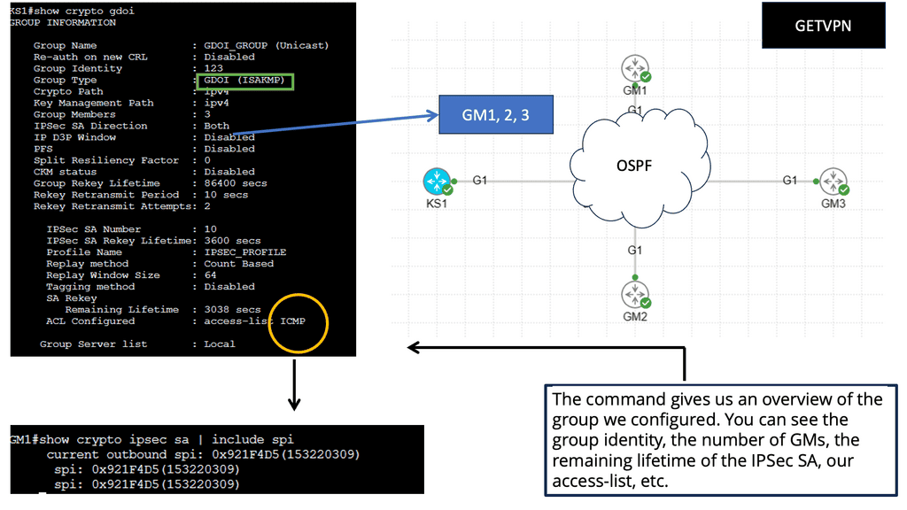
 Example VPN Technology: GETVPN
**Understanding the Basics**
GETVPN, or Group Encrypted Transport VPN, is a protocol designed to secure communication over IP networks. Unlike traditional VPNs that create point-to-point tunnels, GETVPN uses a group key distribution model. This means that data can be securely transmitted between multiple locations without the need to establish individual tunnels. By leveraging the power of group keys, GETVPN provides a scalable and efficient solution for enterprises looking to protect their data.
**Key Features of GETVPN**
One of the standout features of GETVPN is its ability to encrypt traffic without altering the underlying routing infrastructure. This is achieved through its unique architecture that separates the encryption process from the routing process. Moreover, GETVPN supports multicast traffic, making it an ideal choice for organizations that rely on real-time data distribution, such as video conferencing or live streaming services. Additionally, GETVPN enhances network performance by reducing the complexity typically associated with maintaining numerous VPN tunnels.
**Security and Performance Benefits**
The primary objective of GETVPN is to provide robust security while maintaining optimal performance. By using a centralized key server, GETVPN ensures that all devices within the network receive the same group key, allowing for seamless and secure communication. This method not only simplifies the management of encryption keys but also reduces the risk of key compromise. Furthermore, GETVPN’s ability to handle multicast traffic efficiently means that organizations can enjoy high-speed data transmission without compromising on security.

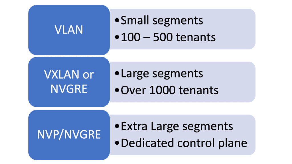
**Overlay Network Types**
Overlay networks are computer networks that are layered on top of other networks (logical instead of physical). They differ from the traditional OSI layered network model and almost always assume that the underlay network is an IP network. These technologies include VXLAN, BGP VPNs, Layer 2 and Layer 3, and IP over IP, such as GRE or IPsec tunnels. Overlay networks, such as SD-WAN, use IP over IP technologies.
The overlay network (SDN overlay) allows multiple network layers to be run on top of each other, adding new applications and improving security. Multiple secure overlays can be created using software over existing networking hardware infrastructure by making virtual connections between two endpoints. In the cloud, endpoints can be physical locations, such as network ports, or logical locations, such as software addresses.
Note: Virtual Tunnels & Software Tags
Software tags, labels, and encryption create a virtual tunnel between two network endpoints. End users must be authenticated to use the connection if encryption is used. Like a phone system, the technology can be considered endpoints with identification tags. An identification tag or number can be used to locate a device in a network, creating virtual connections.
**Benefits of Network Overlays**
1. Simplified Network Management: With network overlays, organizations can manage their networks centrally, using software-defined networking (SDN) controllers. This centralized approach eliminates the need for manual configuration and reduces the complexity associated with traditional network management.
2. Enhanced Scalability: Network overlays enable businesses to scale their networks easily by provisioning virtual networks on demand. This flexibility allows rapid deployment of new services and applications without physical network reconfiguration.
3. Improved Security: Network overlays provide an additional layer of security by encapsulating traffic within virtual tunnels. This isolation helps prevent unauthorized access and reduces the risk of potential security breaches, especially in multi-tenant environments.
4. Interoperability: Network overlays can be deployed across heterogeneous environments, enabling seamless connectivity between different network types, such as private and public clouds. This interoperability extends the network across multiple locations and integrates various cloud services effortlessly.
Service Mesh & Network Overlays
### What is a Service Mesh?
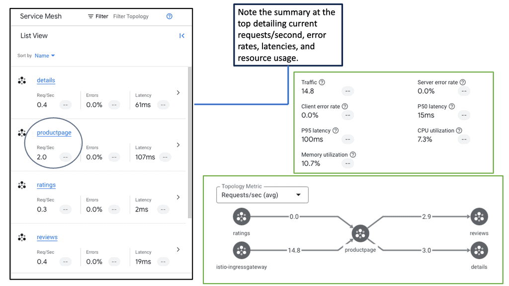
At its core, a service mesh is a network overlay that provides a range of services like traffic management, load balancing, security, and observability to applications without requiring changes to the code. It consists of a data plane and a control plane. The data plane handles the actual communication between services through lightweight proxies, while the control plane configures and manages these proxies.
### Key Benefits of Deploying a Service Mesh
One of the primary benefits of deploying a service mesh is enhanced security. With features such as mutual TLS, service mesh can encrypt the data in transit and ensure that only the intended services communicate with each other. Additionally, service mesh offers advanced traffic management capabilities, such as intelligent routing and retries, which enhance the resilience of applications. Observability is another significant advantage, as service mesh provides detailed metrics and tracing capabilities, enabling teams to monitor the health and performance of their applications closely.
### Service Mesh and Network Overlay
The concept of a network overlay is integral to understanding service mesh. In essence, a network overlay abstracts the complexity of the underlying network by creating a virtual network on top of the physical network infrastructure. This abstraction allows service mesh to seamlessly manage service communication across diverse environments, be it on-premises, cloud, or hybrid setups. By implementing a service mesh, organizations can achieve consistent networking policies and configurations across their distributed services.
Service Mesh Google Cloud
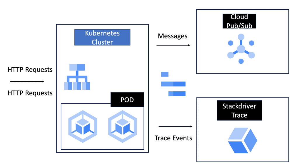
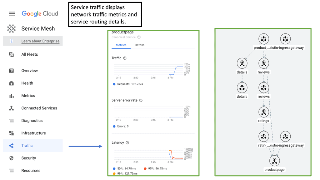
**How Cloud Service Mesh Works**
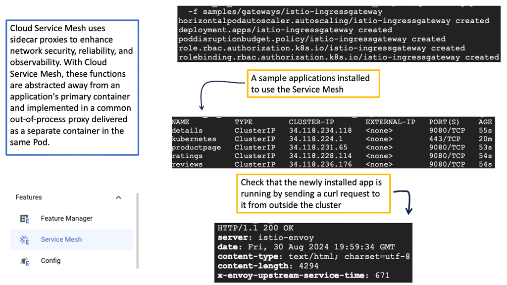
At its core, a cloud service mesh consists of a data plane and a control plane. The data plane is responsible for handling the actual data transfer between services, while the control plane manages the policies and configurations that govern this communication. By deploying sidecar proxies alongside each microservice, the service mesh can intercept and manage all network traffic, ensuring that communication is secure, reliable, and observable.
**Key Benefits of Cloud Service Mesh**
1. **Enhanced Security:** One of the primary advantages of a cloud service mesh is the ability to enforce security policies consistently across all microservices. With features like mutual TLS (mTLS) for encryption, service mesh ensures that data in transit is secure, reducing the risk of breaches.
2. **Observability and Monitoring:** Service mesh provides comprehensive visibility into service-to-service communication. By collecting metrics, logs, and traces, it allows for detailed monitoring and troubleshooting, enabling teams to quickly identify and resolve issues.
3. **Traffic Management:** Advanced traffic management capabilities, such as load balancing, traffic splitting, and circuit breaking, are built into the service mesh. These features ensure that services can handle variable loads and maintain high availability and performance.
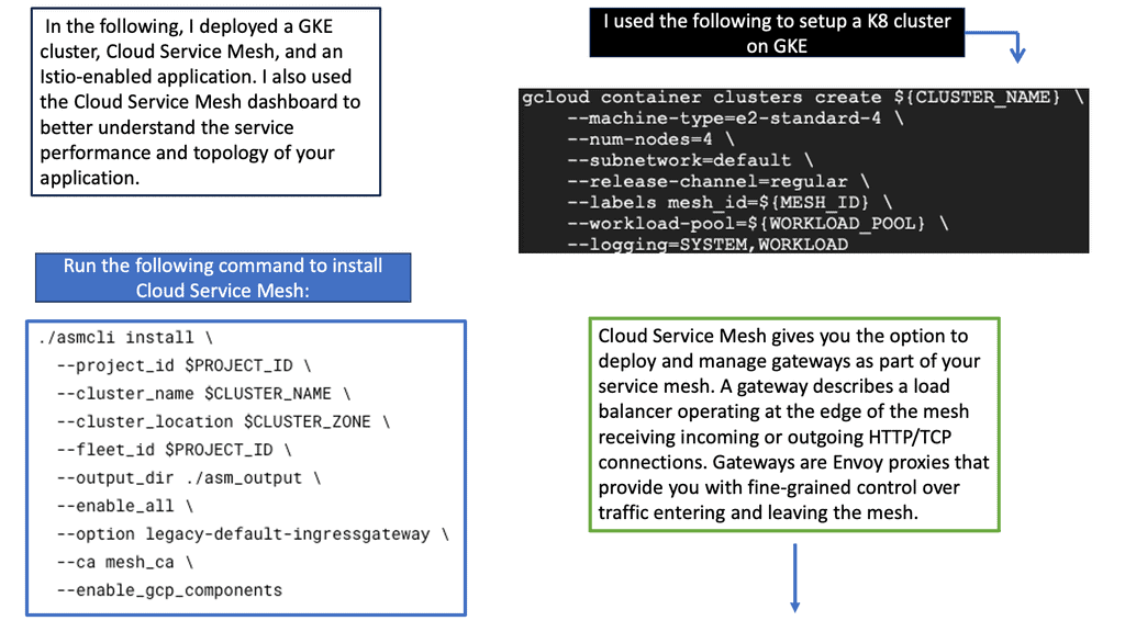
**Implementing a Cloud Service Mesh**
Adopting a cloud service mesh requires careful planning and consideration. Organizations should start by evaluating their current architecture and identifying key areas where a service mesh can bring immediate benefits. It’s also essential to choose the right service mesh solution, such as Istio, Linkerd, or Consul, based on specific needs and compatibility with the existing environment.
**Challenges and Considerations**
While the advantages of a cloud service mesh are clear, there are also challenges to consider. Implementing a service mesh introduces additional complexity and overhead, which can impact performance if not managed properly. It’s crucial to have a thorough understanding of the service mesh architecture and to invest in proper training and support for the team.
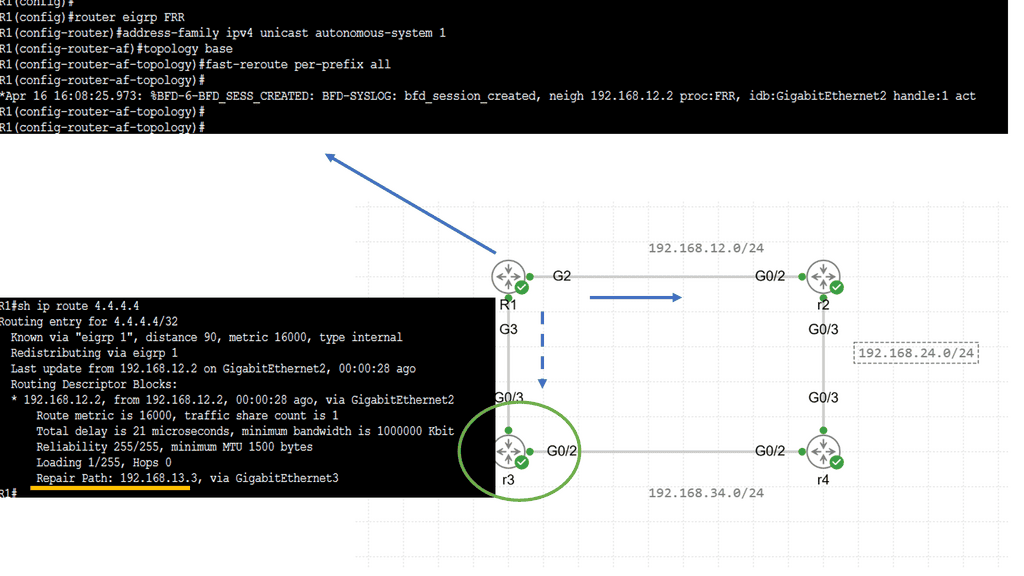
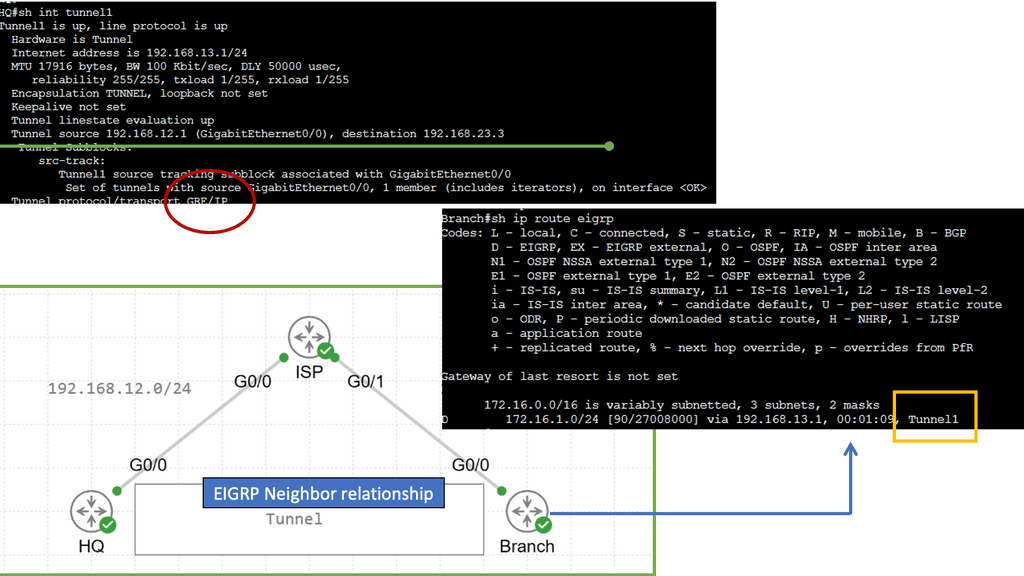
Example Technology: EIGRP and GRE
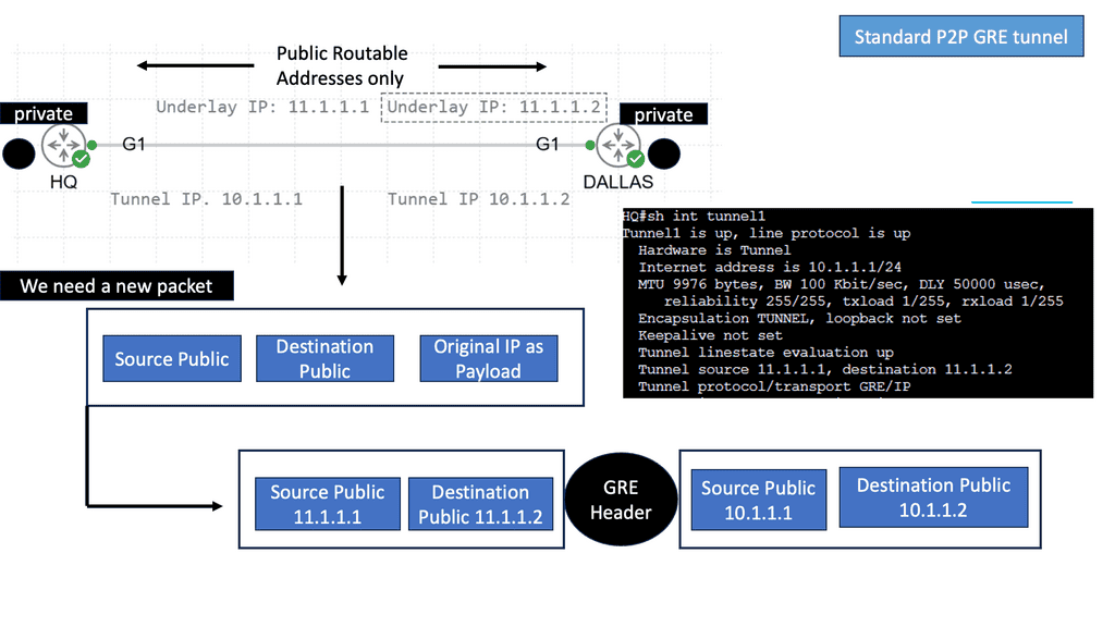
In simple terms, GRE is a tunneling protocol that encapsulates various network layer protocols within IP packets. It establishes a virtual point-to-point connection between different networks, facilitating data transmission across disparate networks. Encapsulating packets within GRE headers allows for secure and efficient communication.
To establish a GRE tunnel, two endpoints are required: a source and a destination. The source endpoint encapsulates the original packet by adding a GRE header, while the destination endpoint decapsulates the packet and forwards it to the appropriate destination. This encapsulation process involves adding an extra IP header, which allows the packet to traverse the network as if it were a regular IP packet.
Networking approach based on overlays
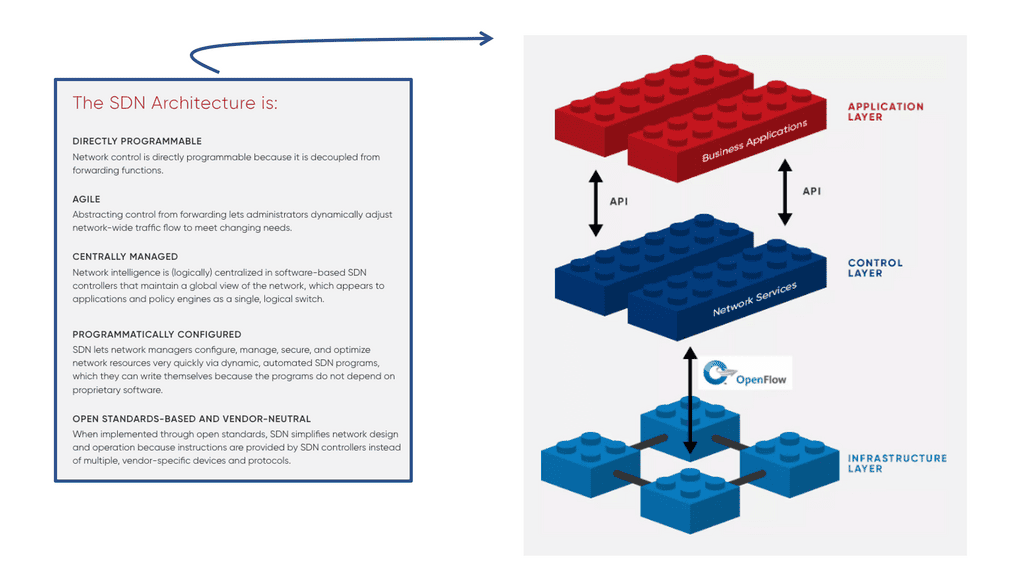
Different overlay networking approaches are often debated in the SDN community. Depending on the technology, some software-only solutions may not be able to integrate at the chip level. The layering of software and processing in overlay networking has been criticized for creating performance overhead. Network overlays are controlled by SDN controllers using the OpenFlow protocol, which requires specific software code or “agents” to be installed.
A -) Change in Traffic Patterns
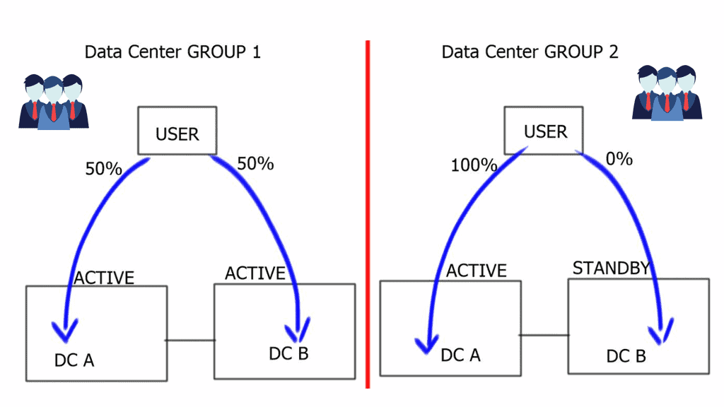
Thanks to the paradigm shift toward cloud computing, a host of physical servers and I/O devices can host multiple virtual servers that share the same logical network despite being in remote locations. In contrast to the traditional north-south direction of data traffic within data centers, virtualization has facilitated more significant east-west data traffic. Communication between servers and applications within a data center is known as east-west traffic.
In corporate networks or on the Internet, much of the data required by the end user involves more complex data that requires preprocessing. Using a web server (via an app server) to access a database as an example of east-west traffic, we can demonstrate the need for preprocessing.
B -) The birth of network overlays
Network virtualization overlays have become the de facto solution for addressing the problems just described regarding data center expansion. Overlays allow existing network technologies to be abstracted, extending the capabilities of classic networks.
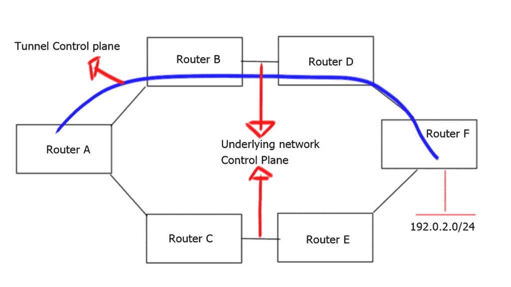
Networking has been using overlays for quite some time. As their name implies, overlays were developed to overcome the disadvantages of conventional networks. An overlay is a tunnel that runs on a physical network infrastructure.
MPLS and GRE Encapsulation
Following MPLS- and GRE-based encapsulations in the 1990s, other tunneling technologies, such as IPsec,8 6in4,9, and L2TPv3,10, also gained popularity. For example, 6in4 tunnels were used to carry payloads over a transport network that could not support the payload type. These tunnels were utilized for security purposes, simplifying routing lookups, or carrying payloads over unsupported transport networks.
Example of GRE Encapsulation
**The Basics of GRE**
At its core, GRE functions as a tunneling protocol that encapsulates a payload, or the original packet, within another packet. This encapsulation allows different types of network layer protocols to be transmitted over a single protocol, such as IP. GRE is particularly useful in scenarios where diverse network architectures need to communicate seamlessly, as it provides a universal solution for protocol encapsulation.
**Advantages of Using GRE**
One of the primary benefits of GRE is its simplicity and versatility. Unlike other tunneling protocols, GRE does not require extensive configuration, making it an attractive option for network administrators. Additionally, GRE supports multicast packets, which is beneficial for applications like streaming and online conferencing. The protocol’s lightweight nature ensures minimal overhead, contributing to efficient data transmission.
**How GRE Operates**
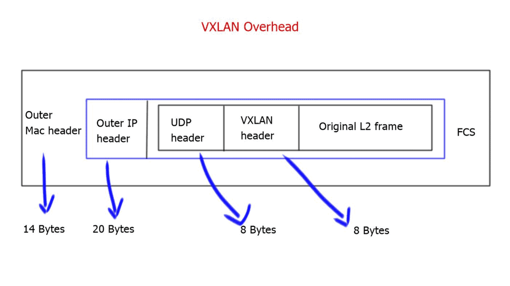
Understanding how GRE operates is essential for leveraging its full potential. When a packet is sent through a GRE tunnel, it is encapsulated with a GRE header and another IP header. This process effectively creates a ‘tunnel’ through which the original data can travel securely and efficiently. The GRE header contains critical information that guides the packet to its destination, ensuring seamless delivery.
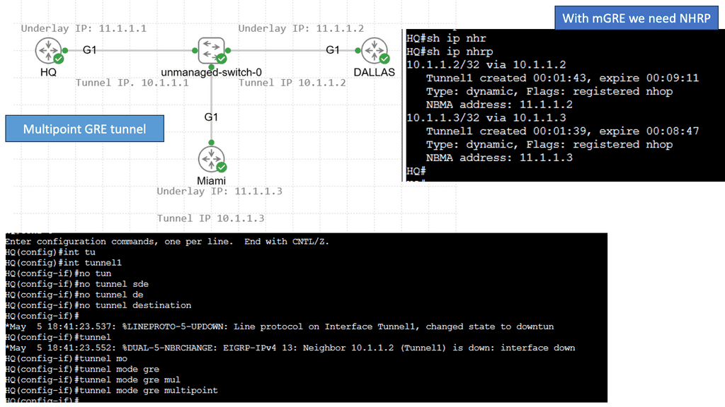
Example – Multipoint GRE with DMVPN
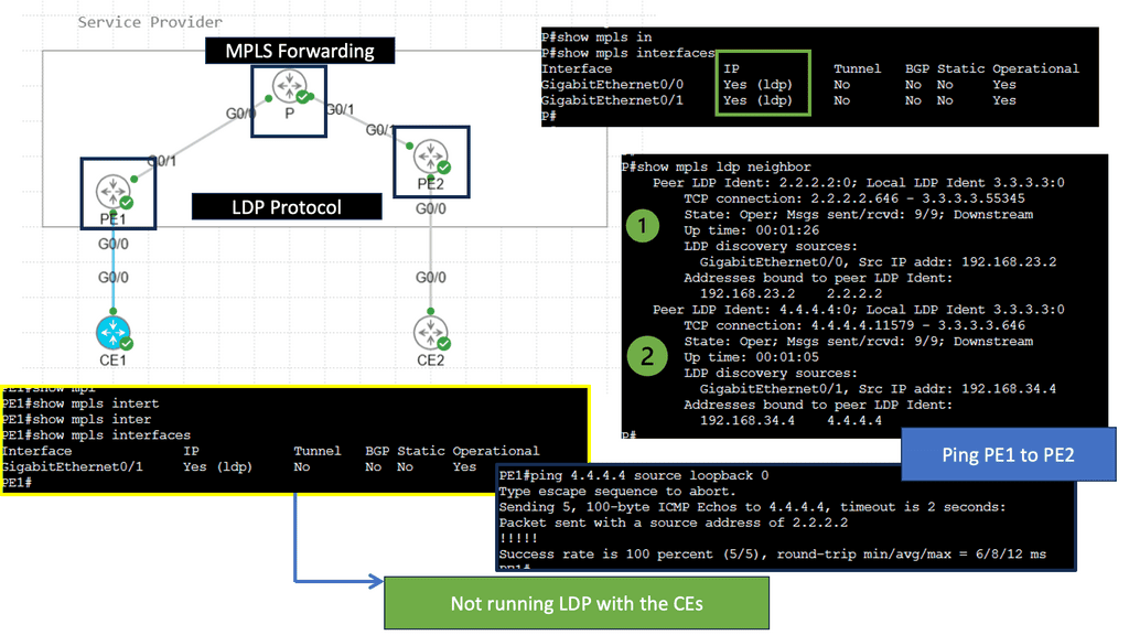
Understanding MPLS Forwarding
MPLS (Multi-Protocol Label Switching) forwarding is used in modern computer networks to route data packets efficiently. Unlike traditional IP routing, which relies on complex table lookups, MPLS forwarding utilizes labels to simplify and expedite packet forwarding. These labels act as virtual shortcuts, enabling faster and more streamlined transmission. To comprehend MPLS forwarding in action, let’s consider a hypothetical scenario of a multinational corporation with branch offices in different countries.
The organization can establish a private network that connects all its branches securely and efficiently by implementing MPLS forwarding. MPLS labels are assigned to packets at the ingress router and guide them through the network, ensuring reliable and optimized data transmission. This enables seamless communication, data sharing, and collaborative workflows across geographically dispersed locations.
What is the LDP Protocol?
The LDP protocol, short for Label Distribution Protocol, is a signaling protocol used in Multiprotocol Label Switching (MPLS) networks. It facilitates the exchange of label mapping information between Label Switching Routers (LSRs), allowing them to establish forwarding equivalence classes (FECs) and efficiently forward data packets.
Label Distribution: The core functionality of the LDP protocol lies in its ability to distribute and assign labels to network paths. These labels help LSRs establish predetermined forwarding paths, enabling faster and more efficient packet forwarding.
Traffic Engineering: Through its Traffic Engineering (TE) extensions, the LDP protocol allows network administrators to optimize the utilization of network resources. Dynamically adjusting label assignments and traffic flows enables better load balancing and network performance.
Network Overlays and Virtual Networks
Network overlays have emerged as a powerful solution to address the challenges of modern networks’ increasing complexity. This blog post will explore network overlays, their benefits, and how they improve connectivity and scalability in today’s digital landscape.
Network overlays are virtual networks that run on physical networks, providing an additional abstraction layer. They allow organizations to create logical networks independent of the underlying physical infrastructure. This decoupling enables flexibility, scalability, and simplified management of complex network architectures.
Virtual Network Services
Network overlays refer to virtualizing network services and infrastructure over existing physical networks. By decoupling the network control plane from the underlying hardware, network overlays provide a layer of abstraction that simplifies network management while offering enhanced flexibility and scalability. This approach allows organizations to create virtual networks tailored to their specific needs without the constraints imposed by physical infrastructure limitations.
Creating an overlay tunnel
A network overlay is an architecture that creates a virtualized network on top of an existing physical network. It allows multiple virtual networks to run independently and securely on the same physical infrastructure. Network overlays are a great way to create a more secure and flexible network environment without investing in new infrastructure.
Network overlays can be used for various applications, such as creating virtual LANs (VLANs), virtual private networks (VPNs), and multicast networks. For example, we have DMVPN (Dynamic Multipoint VPN), with several DMVPN phases providing a secure network technology that allows for multiple sites’ efficient and secure connection.
Example: Cisco DMVPN
### How DMVPN Works
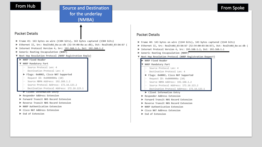
At its core, DMVPN simplifies the creation of secure VPN connections between branch offices and remote users. It leverages a hub-and-spoke architecture but with a dynamic twist. Unlike traditional VPNs that require complex configurations for each connection, DMVPN allows spoke-to-spoke communication without routing all traffic through the hub. This is achieved using multipoint GRE tunnels and Next Hop Resolution Protocol (NHRP), enabling direct and efficient communication paths.
### Benefits of Implementing DMVPN
One of the standout benefits of DMVPN is its scalability. As organizations grow, adding new sites or remote users becomes seamless. The reduction in configuration complexity translates to lower operational costs and quicker deployment times. Moreover, DMVPN enhances network performance by reducing latency and improving bandwidth utilization through direct communication paths. Security is another critical advantage, as DMVPN supports various encryption protocols to ensure that data remains protected across the network.
### DMVPN vs Traditional VPN Solutions
Comparing DMVPN to traditional VPN solutions highlights its superior flexibility and efficiency. While traditional VPNs often require manual configuration for each new connection, DMVPN automates this process, reducing the risk of human error. Additionally, DMVPN’s ability to support dynamic routing protocols ensures optimal routing paths, something static VPNs struggle with. This makes DMVPN particularly appealing for organizations with a dynamic and expanding network topology.

In addition, they can segment traffic and provide secure communication between two or more networks. As a result, network overlays allow for more efficient resource use and provide better performance, scalability, and security.
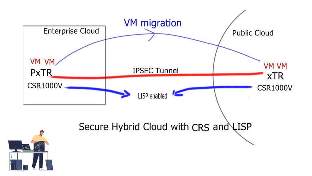
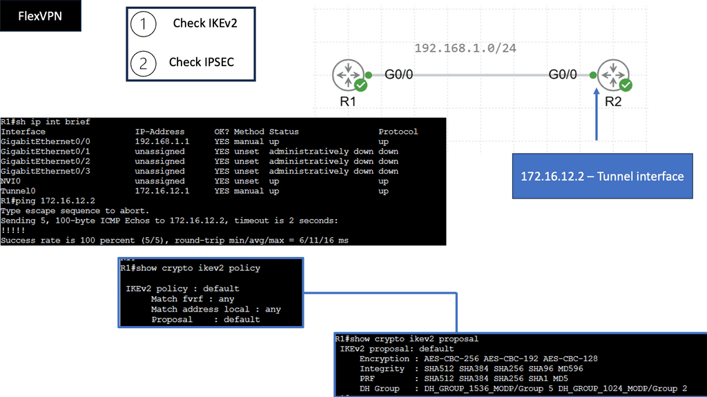
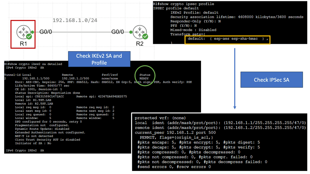
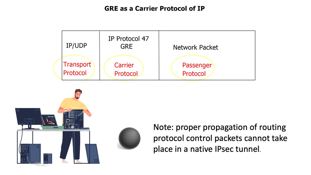
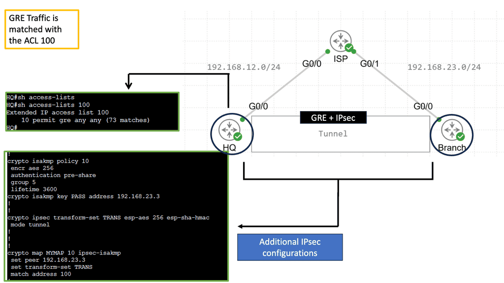
Securing and overlay: GRE and IPSec
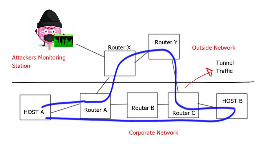
When combined, GRE and IPSec create a robust security infrastructure that addresses tunneling and encryption requirements. GRE tunnels establish secure connections between networks, enabling the transmission of encapsulated packets. IPSec then encrypts these packets, ensuring that data remains confidential and protected from interception. This powerful combination allows organizations to establish secure and private communication channels over untrusted networks like the Internet.
The utilization of GRE and IPSec brings numerous benefits to network security. Firstly, organizations can establish secure and scalable virtual private networks (VPNs) using GRE tunnels, allowing remote employees to access internal resources securely. Secondly, IPSec encryption protects data during transmission, safeguarding against eavesdropping and tampering. Additionally, the combination of GRE and IPSec facilitates secure communication between branch offices, enabling seamless collaboration and data sharing.
Network Overlays Enhanced Connectivity:
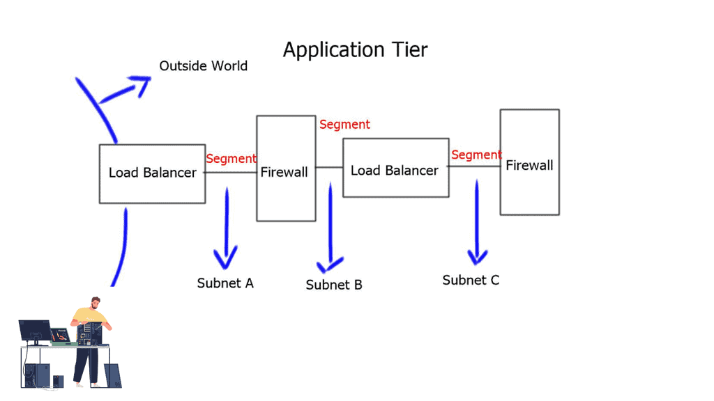
Network overlays improve connectivity by enabling seamless communication between different network domains. By abstracting the underlying physical infrastructure, overlays facilitate the creation of virtual network segments that can span geographical locations, data centers, and cloud environments. This enhanced connectivity promotes better collaboration, data sharing, and application access within and across organizations.
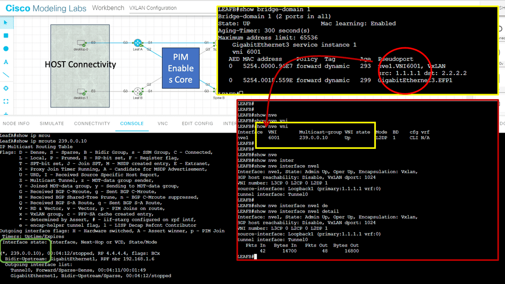
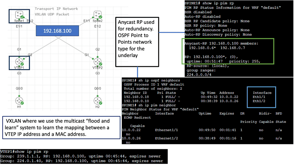
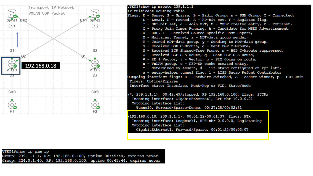
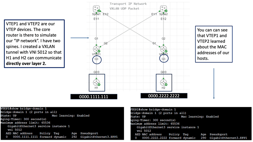
Example: VXLAN Flood and Learn
Unveiling Flood and Learn
– Flood and learn is a fundamental concept in VXLAN that allows hosts to efficiently learn the MAC addresses of virtual machines within the same VXLAN segment. When a host receives an unknown unicast, it floods the packet to all other hosts within the VXLAN segment. The destination host then learns the MAC address and updates its forwarding table accordingly. This process ensures that subsequent packets are directly forwarded to the destination host, minimizing unnecessary flooding.
– In traditional flood and learn implementations, flooding occurs using broadcast or unicast methods, which can lead to significant network congestion. However, by leveraging multicast, VXLAN flood and learn achieve enhanced efficiency and scalability. Multicast groups are established for each VXLAN segment, ensuring unknown unicast packets are only flooded to hosts subscribed to the respective multicast group. This targeted flooding reduces network overhead and optimizes bandwidth utilization.
– VXLAN flood and learn with multicast opens up a world of possibilities in various networking scenarios. From data center virtualization to cloud computing environments, this approach offers benefits such as improved performance, reduced network latency, and simplified network management. It enables seamless communication between virtual machines, even across different physical hosts or clusters, enhancing the flexibility and scalability of virtualized networks.

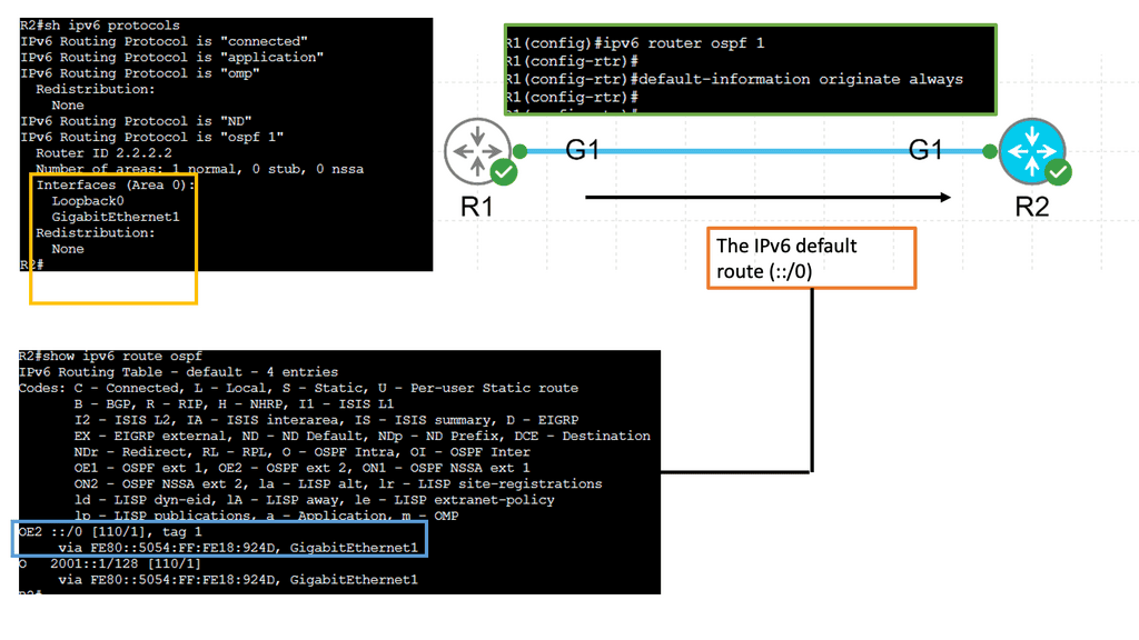
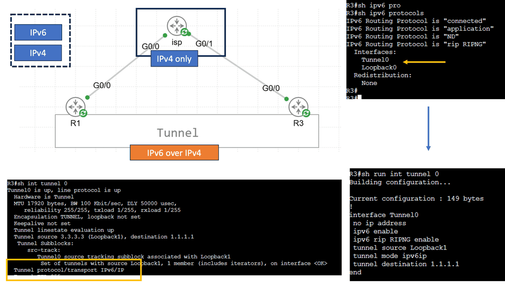
Understanding IPv6 Tunneling
IPv6 tunneling is a mechanism that encapsulates IPv6 packets within IPv4 packets, allowing them to traverse an IPv4 network. This enables communication between IPv6-enabled devices across IPv4-only networks. By encapsulating IPv6 packets within IPv4 packets, tunneling provides a practical solution for the coexistence of both protocols.
**Types of IPv6 Tunneling**
There are several methods for implementing IPv6 tunneling over IPv4, each with advantages and considerations. Let’s explore some popular types:
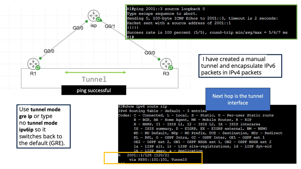
Manual Tunneling: Manual tunneling involves configuring tunnels between IPv6 and IPv4 endpoints. This method requires configuring tunnel endpoints and addressing them, making it suitable for smaller networks or specific scenarios.
Automatic tunneling, also known as 6to4 tunneling, allows for automatically creating IPv6 tunnels over IPv4 networks. It utilizes a 6to4 relay router to facilitate communication between IPv6 and IPv4 networks. Automatic tunneling is relatively easy to set up and does not require manual configuration.
Teredo Tunneling: Teredo tunneling is a mechanism that enables IPv6 connectivity over IPv4 networks, even behind Network Address Translations (NATs). It provides a way for IPv6 traffic to traverse NAT devices by encapsulating IPv6 packets within UDP packets. Teredo tunneling is particularly useful for home networks and scenarios where IPv6 connectivity is limited.
Advanced Topic
DMVPM:
The underlay network forms the foundation of any DMVPN deployment. It consists of the physical infrastructure that connects the various endpoints. The underlay network ensures reliable and efficient data transmission from routers and switches to cables and network protocols. Key considerations in establishing a robust underlay include network design, redundancy, Quality of Service (QoS) policies, and security measures.
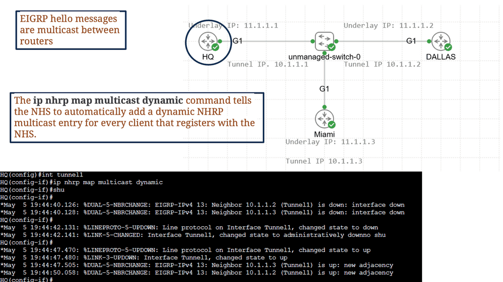
DMVPN truly shines in the overlay network, built on top of the underlay. It enables secure and efficient communication between remote sites, regardless of their physical locations. By leveraging multipoint GRE tunnels and dynamic routing protocols such as EIGRP or OSPF, DMVPN establishes a mesh network that seamlessly connects all endpoints. This overlay architecture eliminates the need for complex and static point-to-point VPN configurations, providing scalability and ease of management.
Benefits and Use Cases:
DMVPN offers a plethora of benefits and is extensively used across various industries. Its ability to provide secure and scalable connectivity makes it ideal for enterprises with multiple branch offices. By utilizing DMVPN, organizations can optimize their network infrastructure, reduce costs associated with traditional VPN solutions, and enhance overall network performance. Additionally, DMVPN enables seamless integration with cloud services and facilitates secure remote access for teleworkers.


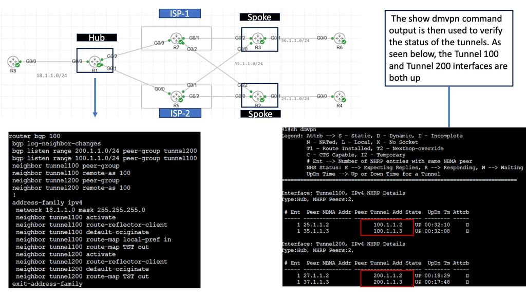
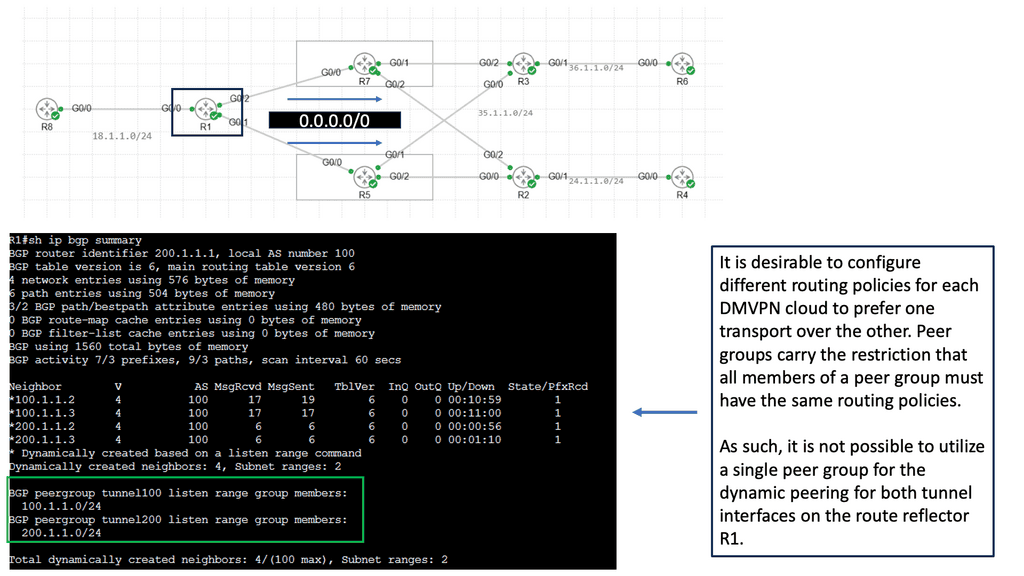
Introducing Single Hub Dual Cloud
The single-hub dual cloud architecture takes DMVPN’s capabilities to the next level. In this setup, a central hub connects to two separate cloud service providers simultaneously, forming redundant paths for traffic. This redundancy ensures high availability and fault tolerance, making it an attractive option for businesses with critical network requirements.
Implementing DMVPN with a single hub dual cloud configuration offers several advantages. Firstly, it enhances network resilience by providing built-in failover capabilities. In a cloud service provider outage, traffic can seamlessly transition to the alternate cloud, minimizing downtime. Additionally, this architecture improves network performance through load balancing, distributing traffic across multiple paths for optimal utilization.
Related: Before you proceed, you may find the following helpful:
- Data Center Topologies
- SD WAN Overlay
- Nexus 1000v
- SDN Data Center
- Virtual Overlay Network
- SD WAN SASE