How does OpenFlow work?
1: OpenFlow allows network controllers to determine the path of network packets in a network of switches. There is a difference between switches and controllers. With separate control and forwarding, traffic management can be more sophisticated than access control lists (ACLs) and routing protocols.
2: An OpenFlow protocol allows switches from different vendors, often with proprietary interfaces and scripting languages, to be managed remotely. Software-defined networking (SDN) is considered to be enabled by OpenFlow by its inventors.
3: With OpenFlow, Layer 3 switches can add, modify, and remove packet-matching rules and actions remotely. By doing so, routing decisions can be made periodically or ad hoc by the controller and translated into rules and actions with a configurable lifespan, which are then deployed to the switch’s flow table, where packets are forwarded at wire speed for the duration of the rule.
The Role of OpenFlow Controllers
If the switch cannot match packets, they can be sent to the controller. The controller can modify existing flow table rules or deploy new rules to prevent a structural traffic flow. It may even forward the traffic itself if the switch is instructed to forward packets rather than just their headers.
OpenFlow uses Transport Layer Security (TLS) over Transmission Control Protocol (TCP). Switches wishing to connect should listen on TCP port 6653. In earlier versions of OpenFlow, port 6633 was unofficially used. The protocol is mainly used between switches and controllers.
### Origins of OpenFlow
The inception of OpenFlow can be traced back to the early 2000s when researchers at Stanford University sought to create a more versatile and programmable network architecture. Traditional networking relied heavily on static and proprietary hardware configurations, which limited innovation and adaptability. OpenFlow emerged as a solution to these challenges, offering a standardized protocol that decouples the network control plane from the data plane. This separation allows for centralized control and dynamic adjustment of network traffic, fostering innovation and agility in network design.
### How OpenFlow Works
At its core, the OpenFlow protocol facilitates communication between network devices and a centralized SDN controller. It does this by using a series of flow tables within network switches, which are programmed by the controller. These flow tables dictate how packets should be handled, whether they are forwarded to a destination, dropped, or modified in some way. By leveraging OpenFlow, network administrators can deploy updates, optimize performance, and troubleshoot issues with unprecedented speed and precision, all from a single point of control.
Introducing SDN
Recent changes and requirements have driven networks and network services to become more flexible, virtualization-aware, and API-driven. One major trend affecting the future of networking is software-defined networking ( SDN ). The software-defined architecture aims to extract the entire network into a single switch.
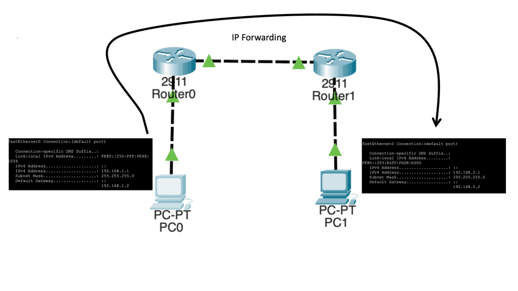
Software-defined networking (SDN) is an evolving technology defined by the Open Networking Foundation ( ONF ). It involves the physical separation of the network control plane from the forwarding plane, where a control plane controls several devices. This differs significantly from traditional IP forwarding that you may have used in the past.
The Core Concepts of SDN
At its heart, Software-Defined Networking decouples the network control plane from the data plane, allowing network administrators to manage network services through abstraction of lower-level functionality. This separation enables centralized network control, which simplifies the management of complex networks. The control plane makes decisions about where traffic is sent, while the data plane forwards traffic to the selected destination. This approach allows for a more flexible, adaptable network infrastructure.
The activities around OpenFlow
Even though OpenFlow has received a lot of industry attention, programmable networks and decoupled control planes (control logic) from data planes have been around for many years. To enhance ATM, Internet, and mobile networks’ openness, extensibility, and programmability, the Open Signaling (OPENING) working group held workshops in 1995. A working group within the Internet Engineering Task Force (IETF) developed GSMP to control label switches based on these ideas. June 2002 marked the official end of this group, and GSMPv3 was published.
Data and control plane
Therefore, SDN separates the data and control plane. The main driving body behind software-defined networking (SDN) is the Open Networking Foundation ( ONF ). Introduced in 2008, the ONF is a non-profit organization that wants to provide an alternative to proprietary solutions that limit flexibility and create vendor lock-in.
The insertion of the ONF allowed its members to run proof of concepts on heterogeneous networking devices without requiring vendors to expose their software’s internal code. This creates a path for an open-source approach to networking and policy-based controllers.
Knowledge Check: Data & Control Plane
### Data Plane: The Highway for Your Data
The data plane, often referred to as the forwarding plane, is responsible for the actual movement of packets of data from source to destination. Imagine it as a network’s highway, where data travels at high speed. This component operates at the speed of light, handling massive amounts of data with minimal delay. It’s designed to process packets quickly, ensuring that the information arrives where it needs to be without interruption.
### Control Plane: The Brain Behind the Operation
While the data plane acts as the highway, the control plane is the brain that orchestrates the flow of traffic. It makes decisions about routing, managing the network topology, and controlling the data plane’s operations. The control plane uses protocols to determine the best paths for data and to update routing tables as needed. It’s responsible for ensuring that the network operates efficiently, adapting to changes, and maintaining optimal performance.
### Interplay Between Data and Control Planes
The synergy between the data and control planes is what enables modern networks to function effectively. The control plane provides the intelligence and decision-making necessary to guide the data plane. This interaction ensures that data packets take the best possible paths, reducing latency and maximizing throughput. As networks evolve, the lines between these planes may blur, but their distinct roles remain pivotal.
### Real-World Applications and Innovations
The concepts of data and control planes are not just theoretical—they have practical applications in technologies such as Software-Defined Networking (SDN) and Network Function Virtualization (NFV). These innovations allow for greater flexibility and scalability in managing network resources, offering businesses the agility needed to adapt to changing demands.
Building blocks: SDN Environment
As a fundamental building block of an SDN deployment, the controller, the SDN switch (for example, an OpenFlow switch), and the interfaces are present in the controller to communicate with forwarding devices, generally the southbound interface (OpenFlow) and the northbound interface (the network application interface).
In an SDN, switches function as basic forwarding hardware, accessible via an open interface, with the control logic and algorithms offloaded to controllers. Hybrid (OpenFlow-enabled) and pure (OpenFlow-only) OpenFlow switches are available.
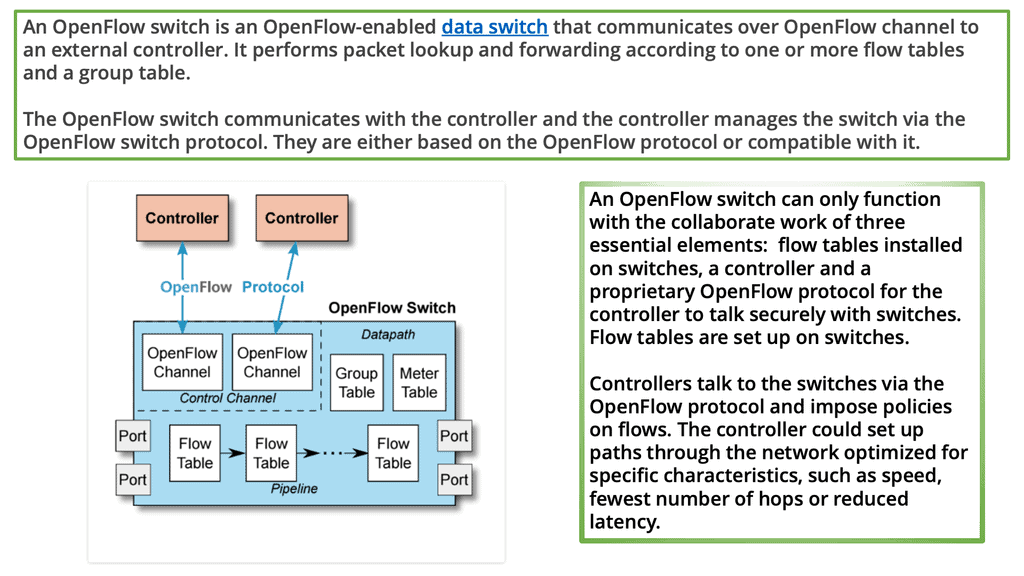
OpenFlow switches rely entirely on a controller for forwarding decisions, without legacy features or onboard control. Hybrid switches support OpenFlow as well, in addition to traditional operation and protocols. Today, hybrid switches are the most common type of commercial switch. A flow table performs packet lookup and forwarding in an OpenFlow switch.
### The Role of the OpenFlow Controller
The OpenFlow controller is the brain of the SDN, orchestrating the flow of data across the network. It communicates with the network devices using the OpenFlow protocol to dictate how packets should be handled. The controller’s primary function is to make decisions on the path data packets should take, ensuring optimal network performance and resource utilization. This centralization of control allows for dynamic network configuration, paving the way for innovative applications and services.
### OpenFlow Switches: The Workhorses of the Network
While the controller is the brain, OpenFlow switches are the workhorses, executing the instructions they receive. These switches operate at the data plane, where they forward packets based on the rules set by the controller. Each switch maintains a flow table that matches incoming packets to particular actions, such as forwarding or dropping the packet. This separation of control and data planes is what sets SDN apart from traditional networking, offering unparalleled flexibility and control.
### Flow Tables: The Heart of OpenFlow Switches
Flow tables are the core component of OpenFlow switches, dictating how packets are handled. Each entry in a flow table consists of match fields, counters, and a set of instructions. Match fields identify the packets that should be affected by the rule, counters track the number of packets and bytes that match the entry, and instructions define the actions to be taken. This modular approach allows for precise traffic management and is essential for implementing advanced network policies.
OpenFlow Table & Routing Tables
### What is an OpenFlow Flow Table?
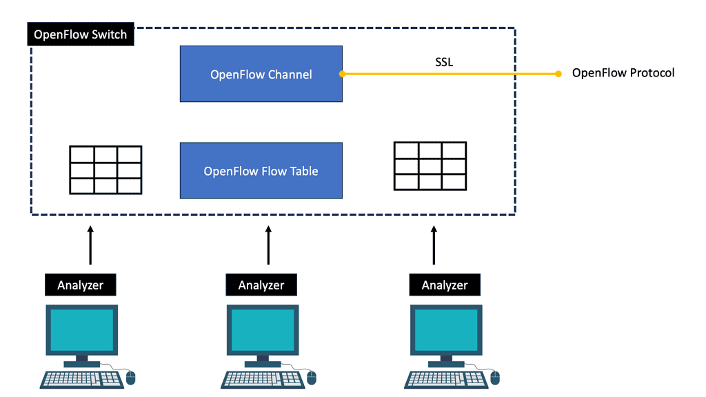
OpenFlow is a protocol that allows network controllers to interact with the forwarding plane of network devices like switches and routers. At the heart of OpenFlow is the flow table. This table contains a set of flow entries, each specifying actions to take on packets that match a particular pattern. Unlike traditional routing tables, which rely on predefined paths and protocols, OpenFlow flow tables provide flexibility and programmability, allowing dynamic changes in how packets are handled based on real-time network conditions.
### Understanding Routing Tables
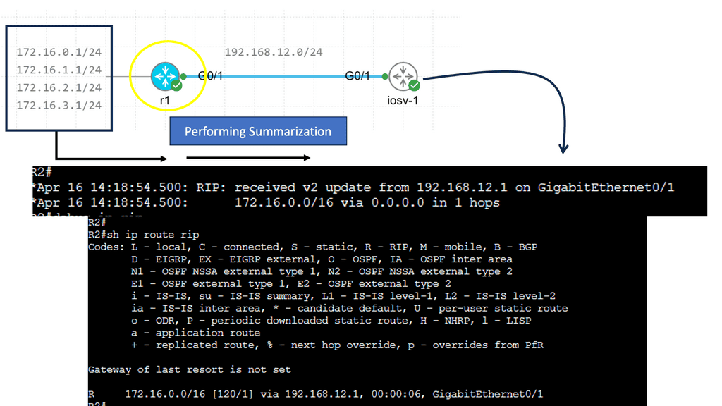
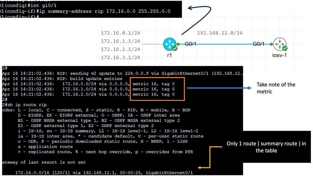
Routing tables are a staple of traditional networking, used by routers to determine the best path for forwarding packets to their final destinations. These tables consist of a list of network destinations, with associated metrics that help in selecting the most efficient route. Routing protocols such as OSPF, BGP, and RIP are employed to maintain and update these tables, ensuring that data flows smoothly across the interconnected web of networks. While reliable, routing tables are less flexible compared to OpenFlow flow tables, as changes in network traffic patterns require updates to routing protocols and configurations.
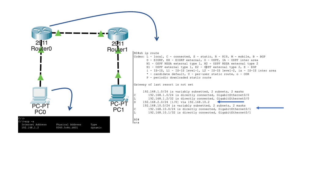
Example of a Routing Table
### Key Differences Between OpenFlow Flow Table and Routing Table
The primary distinction between OpenFlow flow tables and routing tables lies in their approach to network management. OpenFlow flow tables are dynamic and programmable, allowing for real-time adjustments and fine-grained control over traffic flows. This makes them ideal for environments where network agility and customization are paramount. Conversely, routing tables offer a more static and predictable method of packet forwarding, which can be beneficial in stable networks where consistency and reliability are prioritized.
### Use Cases: When to Use Each
OpenFlow flow tables are particularly advantageous in software-defined networking (SDN) environments, where network administrators need to quickly adapt to changing conditions and optimize traffic flows. They are well-suited for data centers, virtualized networks, and scenarios requiring high levels of automation and scalability. On the other hand, traditional routing tables are best used in established networks with predictable traffic patterns, such as those found in enterprise or service provider settings, where reliability and stability are key.
You may find the following useful for pre-information:
What is OpenFlow?
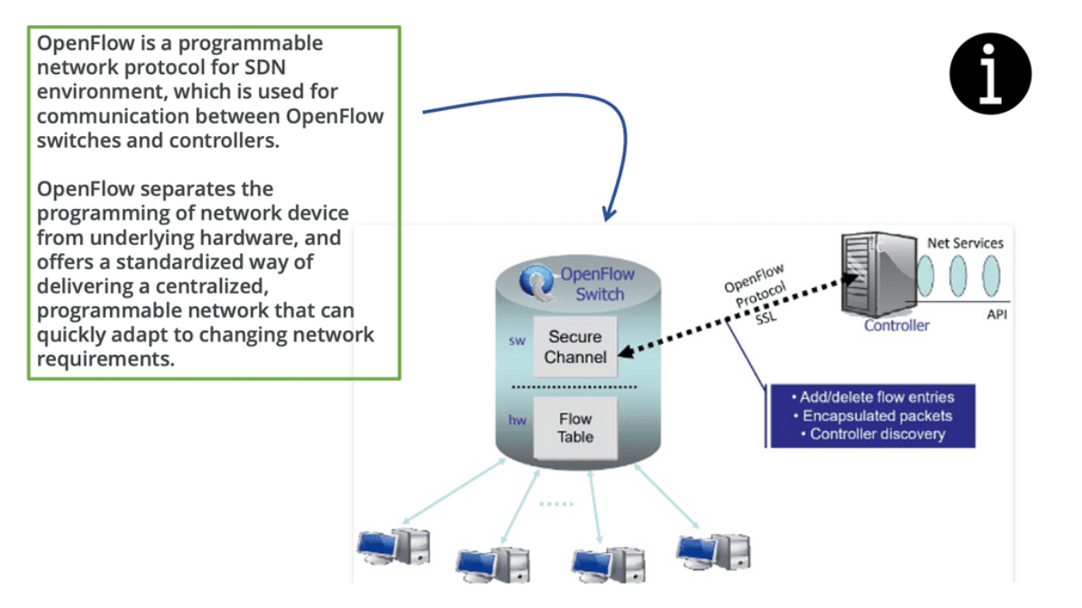
OpenFlow was the first protocol of the Software-Defined Networking (SDN) trend and is the only protocol that allows the decoupling of a network device’s control plane from the data plane. In most straightforward terms, the control plane can be thought of as the brains of a network device. On the other hand, the data plane can be considered hardware or application-specific integrated circuits (ASICs) that perform packet forwarding.
Numerous devices also support running OpenFlow in a hybrid mode, meaning OpenFlow can be deployed on a given port, virtual local area network (VLAN), or even within a regular packet-forwarding pipeline such that if there is not a match in the OpenFlow table, then the existing forwarding tables (MAC, Routing, etc.) are used, making it more analogous to Policy Based Routing (PBR).

What is SDN?
Despite various modifications to the underlying architecture and devices (such as switches, routers, and firewalls), traditional network technologies have existed since the inception of networking. Using a similar approach, frames and packets have been forwarded and routed in a limited manner, resulting in low efficiency and high maintenance costs. Consequently, the architecture and operation of networks need to evolve, resulting in SDN.
By enabling network programmability, SDN promises to simplify network control and management and allow innovation in computer networking. Network engineers configure policies to respond to various network events and application scenarios. They can achieve the desired results by manually converting high-level policies into low-level configuration commands.
Often, minimal tools are available to accomplish these very complex tasks. Controlling network performance and tuning network management are challenging and error-prone tasks.
A modern network architecture consists of a control plane, a data plane, and a management plane; the control and data planes are merged into a machine called Inside the Box. To overcome these limitations, programmable networks have emerged.
How OpenFlow Works:
At the core of OpenFlow is the concept of a flow table, which resides in each OpenFlow-enabled switch. The flow table contains match-action rules defining how incoming packets should be processed and forwarded. The centralized controller determines these rules and communicates using the OpenFlow protocol with the switches.
When a packet arrives at an OpenFlow-enabled switch, it is first matched against the rules in the flow table. If a match is found, the corresponding action is executed, including forwarding the packet, dropping it, or sending it to the controller for further processing. This decoupling of the control and data planes allows for flexible and programmable network management.
What is OpenFlow SDN?
The main goal of SDN is to separate the control and data planes and transfer network intelligence and state to the control plane. These concepts have been exploited by technologies like Routing Control Platform (RCP), Secure Architecture for Network Enterprise (SANE), and, more recently, Ethane.
In addition, there is often a connection between SDN and OpenFlow. The Open Networking Foundation (ONF) is responsible for advancing SDN and standardizing OpenFlow, whose latest version is 1.5.0.
An SDN deployment starts with these building blocks.
For communication with forwarding devices, the controller has the SDN switch (for example, an OpenFlow switch), the SDN controller, and the interfaces. An SDN deployment is based on two basic building blocks: a southbound interface (OpenFlow) and a northbound interface (the network application interface).
As the control logic and algorithms are offloaded to a controller, switches in SDNs may be represented as basic forwarding hardware. Switches that support OpenFlow come in two varieties: pure (OpenFlow-only) and hybrid (OpenFlow-enabled).
Pure OpenFlow switches do not have legacy features or onboard control for forwarding decisions. A hybrid switch can operate with both traditional protocols and OpenFlow. Hybrid switches make up the majority of commercial switches available today. In an OpenFlow switch, a flow table performs packet lookup and forwarding.
OpenFlow reference switch
The OpenFlow protocol and interface allow OpenFlow switches to be accessed as essential forwarding elements. A flow-based SDN architecture like OpenFlow simplifies switching hardware. Still, it may require additional forwarding tables, buffer space, and statistical counters that are difficult to implement in traditional switches with integrated circuits tailored to specific applications.
There are two types of switches in an OpenFlow network: hybrids (which enable OpenFlow) and pores (which only support OpenFlow). OpenFlow is supported by hybrid switches and traditional protocols (L2/L3). OpenFlow switches rely entirely on a controller for forwarding decisions and do not have legacy features or onboard control.
Hybrid switches are the majority of the switches currently available on the market. This link must remain active and secure because OpenFlow switches are controlled over an open interface (through a TCP-based TLS session). OpenFlow is a messaging protocol that defines communication between OpenFlow switches and controllers, which can be viewed as an implementation of SDN-based controller-switch interactions.
Identify the Benefits of OpenFlow
Application-driven routing. Users can control the network paths. | The networks paths.A way to enhance link utilization. |
An open solution for VM mobility. No VLAN reliability. | A means to traffic engineer without MPLS. |
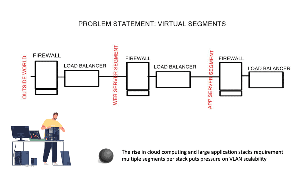
A solution to build very large Layer 2 networks. | A way to scale Firewalls and Load Balancers. |
A way to configure an entire network as a whole as opposed to individual entities. | A way to build your own encryption solution. Off-the-box encryption. |
A way to distribute policies from a central controller. | Customized flow forwarding. Based on a variety of bit patterns. |
A solution to get a global view of the network and its state. End-to-end visibility. | A solution to use commodity switches in the network. Massive cost savings. |
The following table lists the Software Networking ( SDN ) benefits and the problems encountered with existing control plane architecture:
Identify the benefits of OpenFlow and SDN | Problems with the existing approach |
Faster software deployment. | Large scale provisioning and orchestration. |
Programmable network elements. | Limited traffic engineering ( MPLS TE is cumbersome ) |
Faster provisioning. | Synchronized distribution policies. |
Centralized intelligence with centralized controllers. | Routing of large elephant flows. |
Decisions are based on end-to-end visibility. | Qos and load based forwarding models. |
Granular control of flows. | Ability to scale with VLANs. |
Decreases the dependence on network appliances like load balancers. |
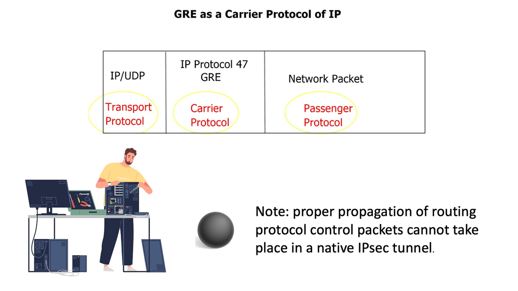
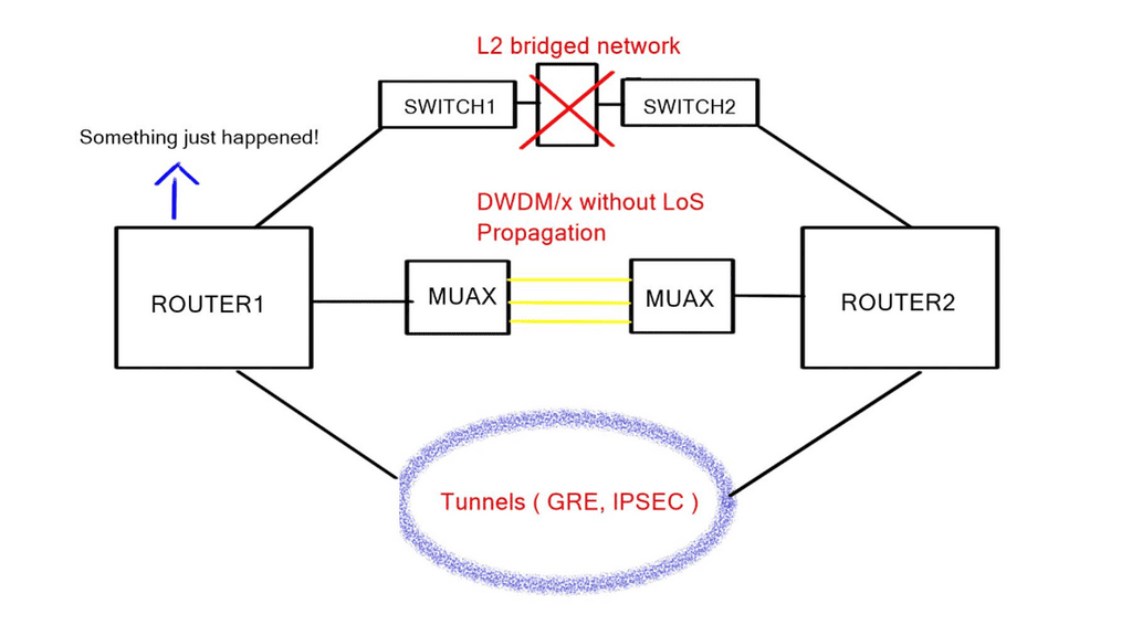
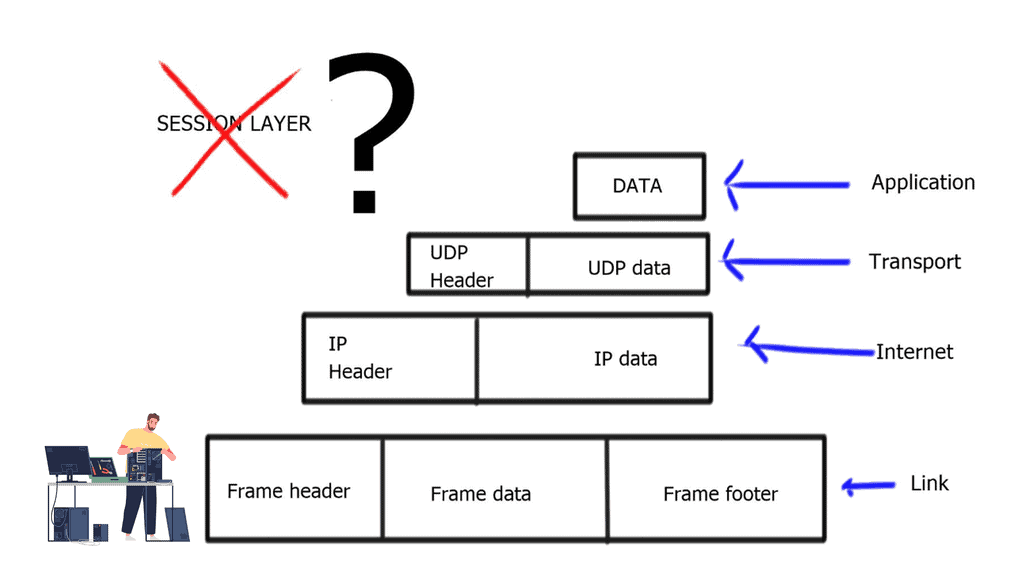
**A key point: The lack of a session layer in the TCP/IP stack**
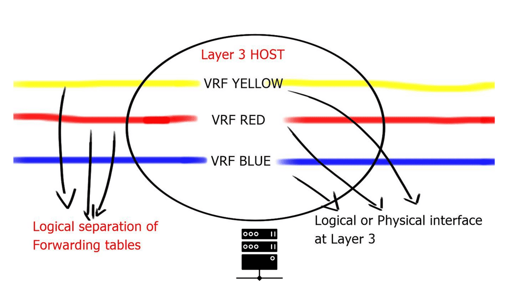
Regardless of the hype and benefits of SDN, neither OpenFlow nor other SDN technologies address the real problems of the lack of a session layer in the TCP/IP protocol stack. The problem is that the client’s application ( Layer 7 ) connects to the server’s IP address ( Layer 3 ), and if you want to have persistent sessions, the server’s IP address must remain reachable.
This session’s persistence and the ability to connect to multiple Layer 3 addresses to reach the same device is the job of the OSI session layer. The session layer provides the services for opening, closing, and managing a session between end-user applications. In addition, it allows information from different sources to be correctly combined and synchronized.
The problem is the TCP/IP reference module does not consider a session layer, and there is none in the TCP/IP protocol stack. SDN does not solve this; it gives you different tools to implement today’s kludges.
Control and data plane
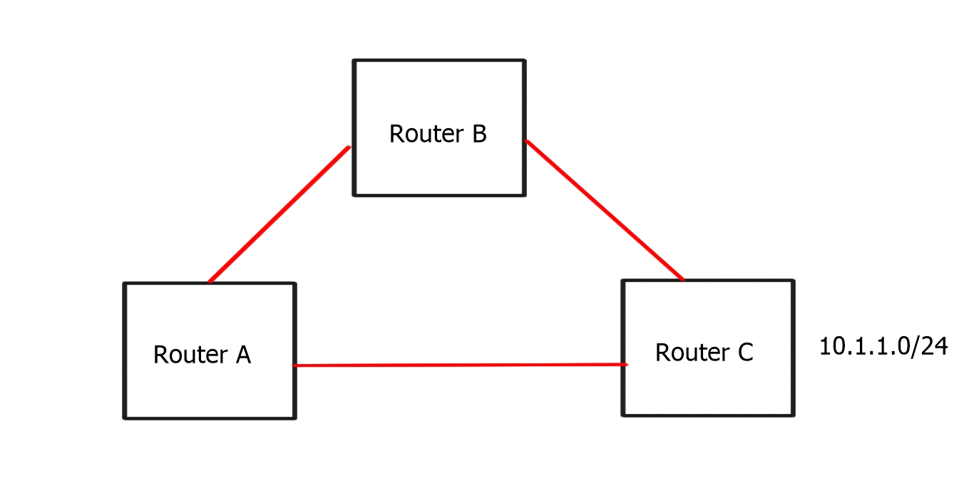
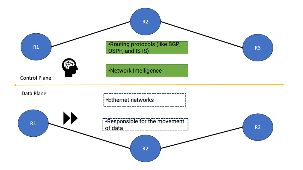
When we identify the benefits of OpenFlow, let us first examine traditional networking operations. Traditional networking devices have a control and forwarding plane, depicted in the diagram below. The control plane is responsible for setting up the necessary protocols and controls so the data plane can forward packets, resulting in end-to-end connectivity. These roles are shared on a single device, and the fast packet forwarding ( data path ) and the high-level routing decisions ( control path ) occur on the same device.
What is OpenFlow | SDN separates the data and control plane?
**Control plane**
The control plane is part of the router architecture and is responsible for drawing the network map in routing. When we mention control planes, you usually think about routing protocols, such as OSPF or BGP. But in reality, the control plane protocols perform numerous other functions, including:
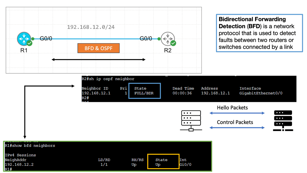
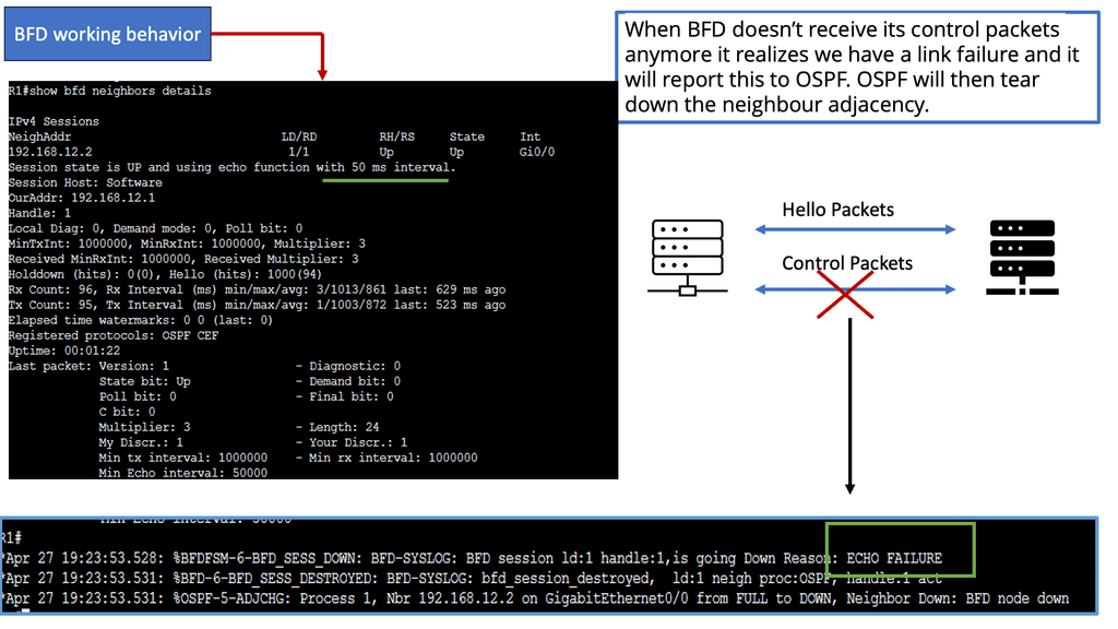
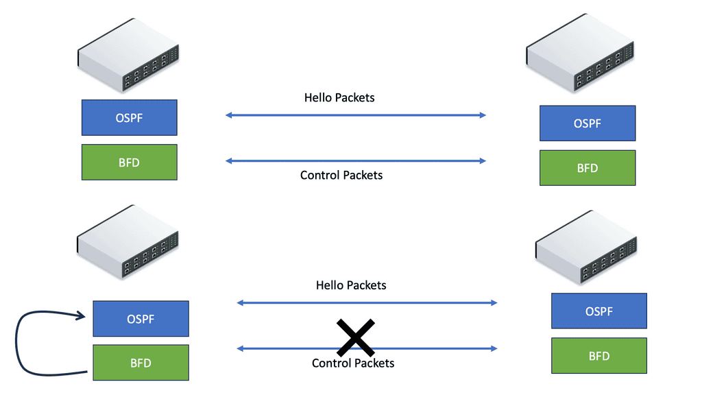
Connectivity management ( BFD, CFM ) | Interface state management ( PPP, LACP ) |
Service provisioning ( RSVP for InServ or MPLS TE) | Topology and reachability information exchange ( IP routing protocols, IS-IS in TRILL/SPB ) |
Adjacent device discovery via HELLO mechanism | ICMP |
Control plane protocols run over data plane interfaces to ensure “shared fate” – if the packet forwarding fails, the control plane protocol fails as well.
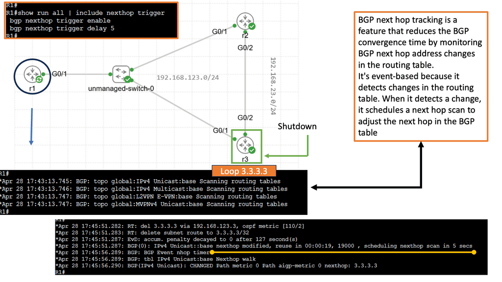
Most control plane protocols ( BGP, OSPF, BFD ) are not data-driven. A BGP or BFD packet is never sent as a direct response to a data packet. There is a question mark over the validity of ICMP as a control plane protocol. The debate is whether it should be classed in the control or data plane category.
Some ICMP packets are sent as replies to other ICMP packets, and others are triggered by data plane packets, i.e., data-driven. My view is that ICMP is a control plane protocol that is triggered by data plane activity. After all, the “C” is ICMP does stand for “Control.”
**Data plane**
The data path is part of the routing architecture that decides what to do when a packet is received on its inbound interface. It is primarily focused on forwarding packets but also includes the following functions:
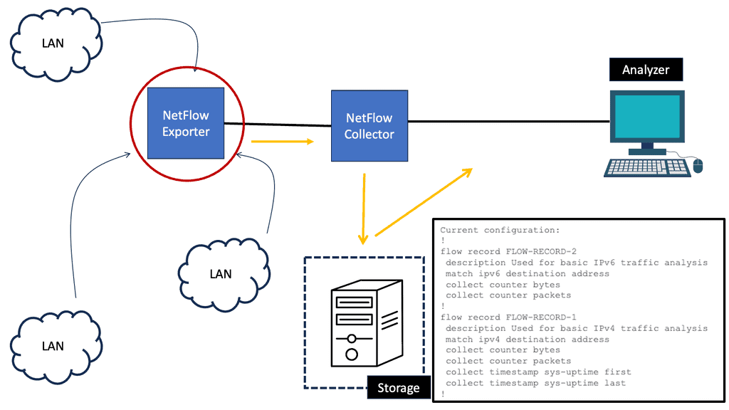
ACL logging | Netflow accounting |
NAT session creation | NAT table maintenance |
The data forwarding is usually performed in dedicated hardware, while the additional functions ( ACL logging, Netflow accounting ) typically happen on the device CPU, commonly known as “punting.” The data plane for an OpenFlow-enabled network can take a few forms.
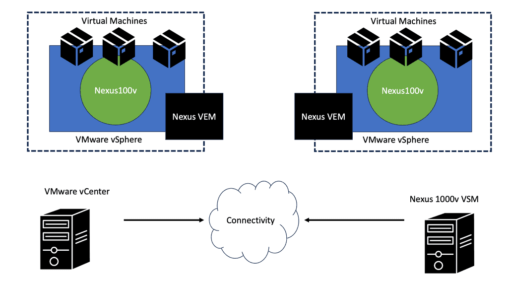
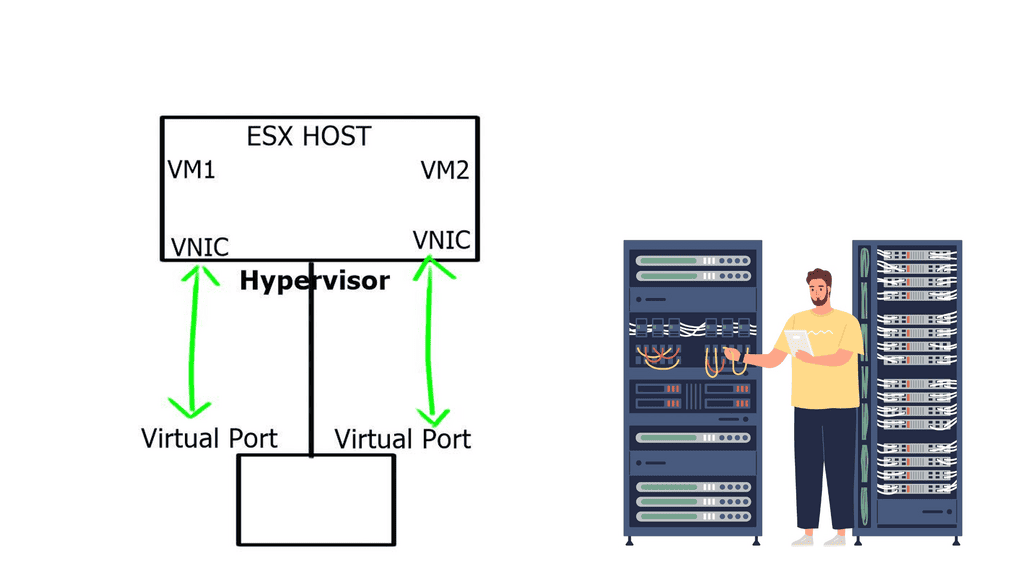
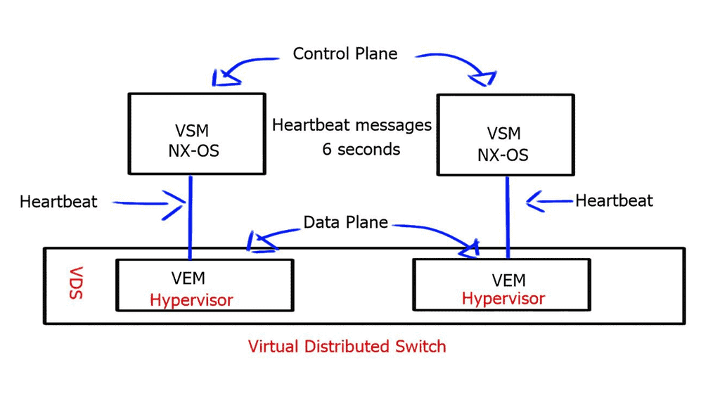
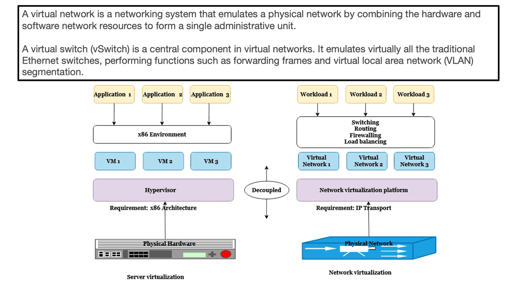
However, the most common, even in the commercial offering, is the Open vSwitch, often called the OVS. The Open vSwitch is an open-source implementation of a distributed virtual multilayer switch. It enables a switching stack for virtualization environments while supporting multiple protocols and standards.
Software-defined networking changes the control and data plane architecture.
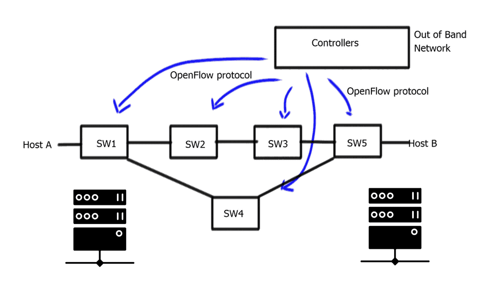
The concept of SDN separates these two planes, i.e., the control and forwarding planes are decoupled. This allows the networking devices in the forwarding path to focus solely on packet forwarding. An out-of-band network uses a separate controller ( orchestration system ) to set up the policies and controls. Hence, the forwarding plane has the correct information to forward packets efficiently.
In addition, it allows the network control plane to be moved to a centralized controller on a server instead of residing on the same box carrying out the forwarding. Moving the intelligence ( control plane ) of the data plane network devices to a controller enables companies to use low-cost, commodity hardware in the forwarding path. A significant benefit is that SDN separates the data and control plane, enabling new use cases.
A centralized computation and management plane makes more sense than a centralized control plane.
The controller maintains a view of the entire network and communicates with Openflow ( or, in some cases, BGP with BGP SDN ) with the different types of OpenFlow-enabled network boxes. The data path portion remains on the switch, such as the OVS bridge, while the high-level decisions are moved to a separate controller. The data path presents a clean flow table abstraction, and each flow table entry contains a set of packet fields to match, resulting in specific actions ( drop, redirect, send-out-port ).
When an OpenFlow switch receives a packet it has never seen before and doesn’t have a matching flow entry, it sends the packet to the controller for processing. The controller then decides what to do with the packet.
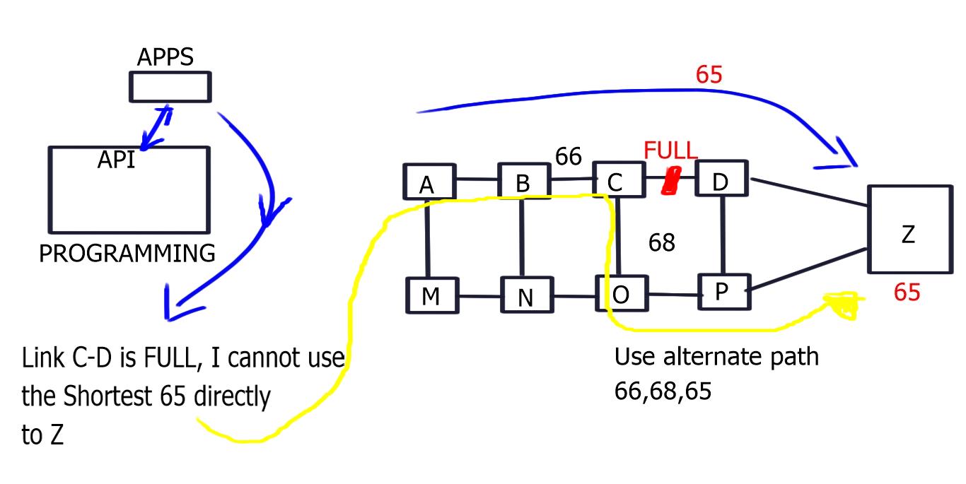
Applications could then be developed on top of this controller, performing security scrubbing, load balancing, traffic engineering, or customized packet forwarding. The centralized view of the network simplifies problems that were harder to overcome with traditional control plane protocols.
A single controller could potentially manage all OpenFlow-enabled switches. Instead of individually configuring each switch, the controller can push down policies to multiple switches simultaneously—a compelling example of many-to-one virtualization.
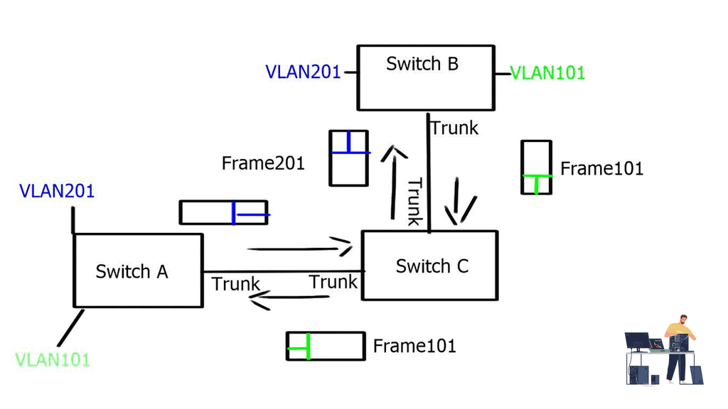
Now that SDN separates the data and control plane, the operator uses the centralized controller to choose the correct forwarding information per-flow basis. This allows better load balancing and traffic separation on the data plane. In addition, there is no need to enforce traffic separation based on VLANs, as the controller would have a set of policies and rules that would only allow traffic from one “VLAN” to be forwarded to other devices within that same “VLAN.”
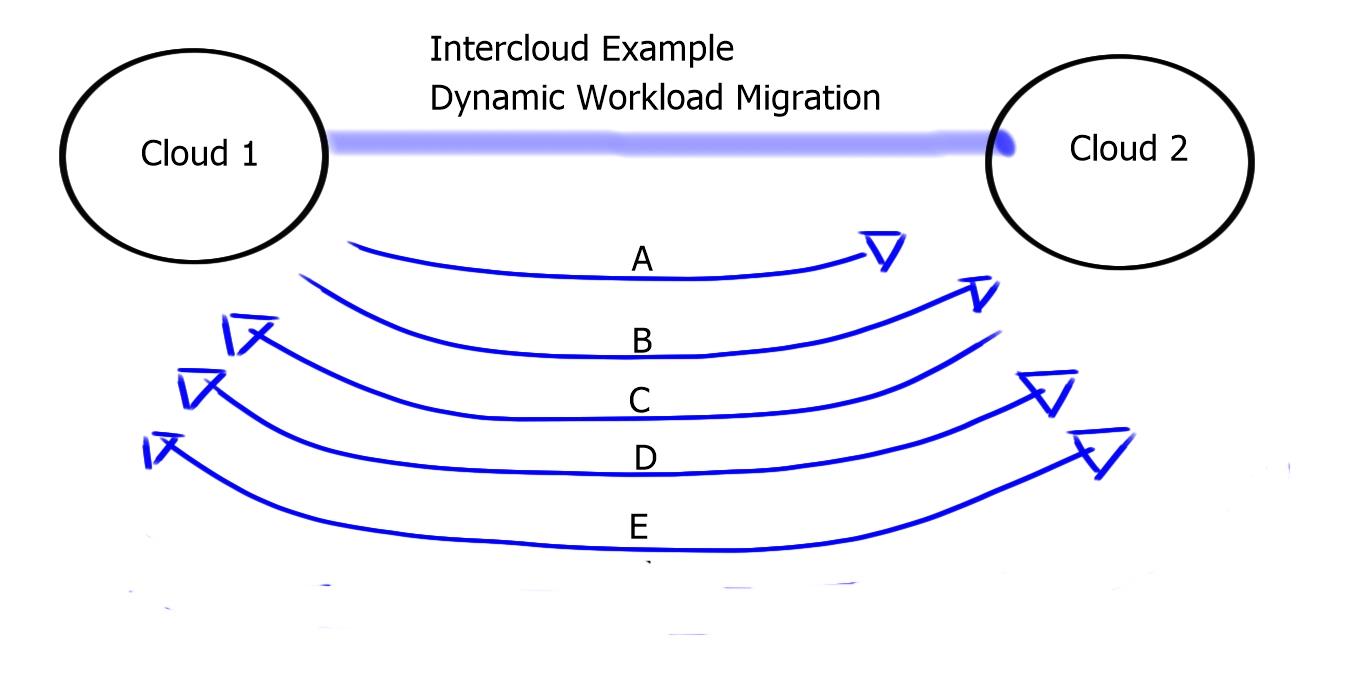
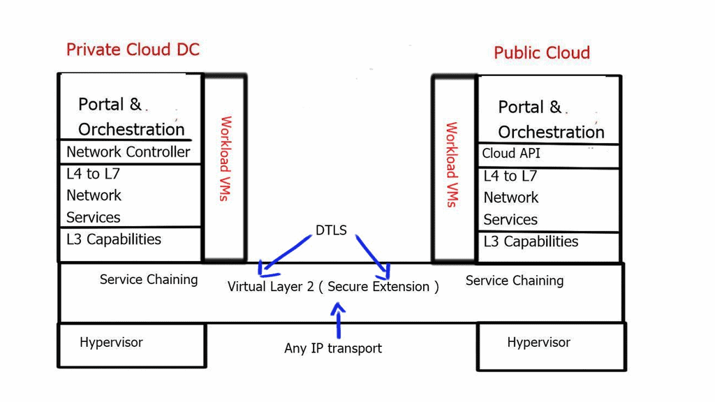
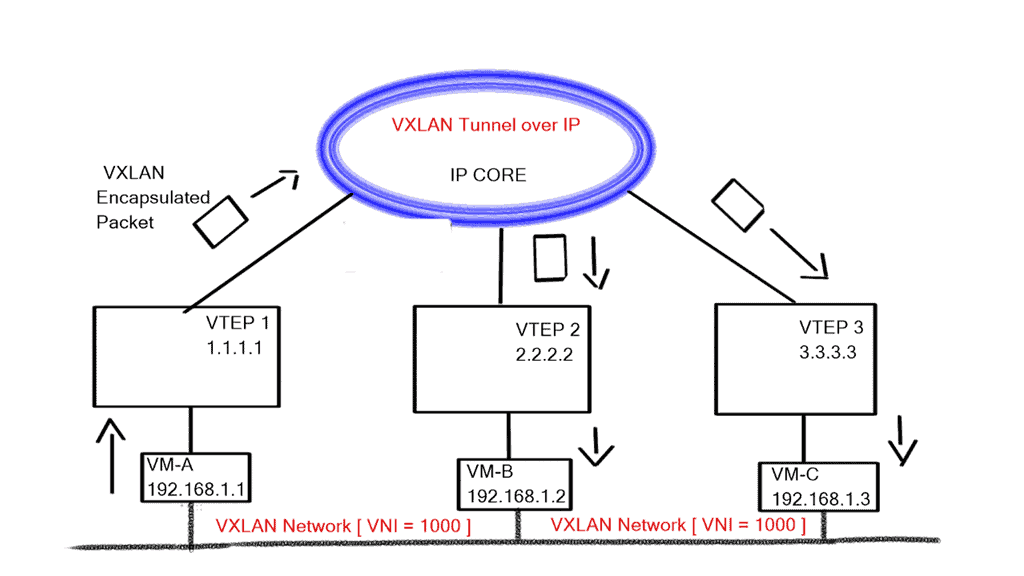
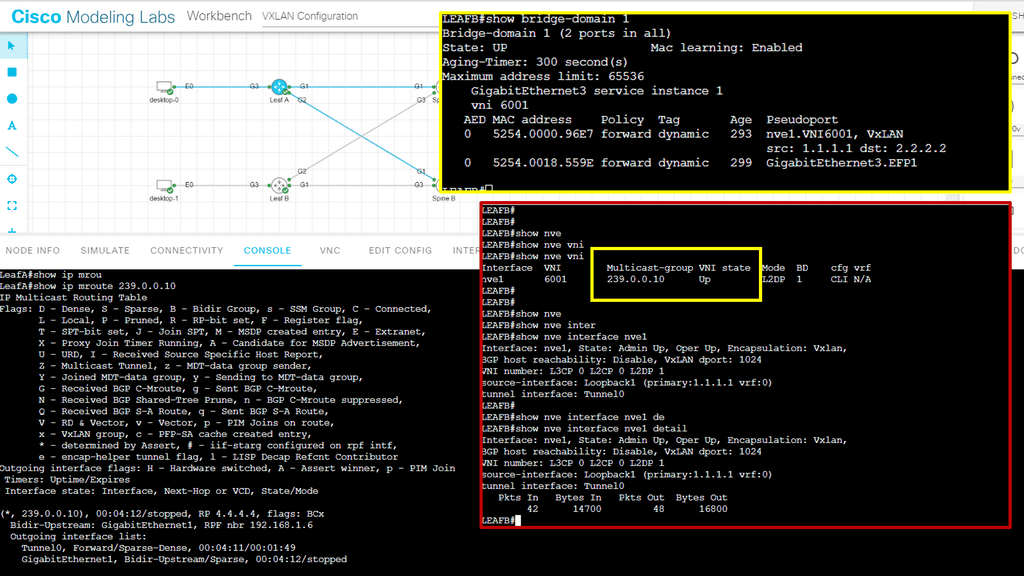
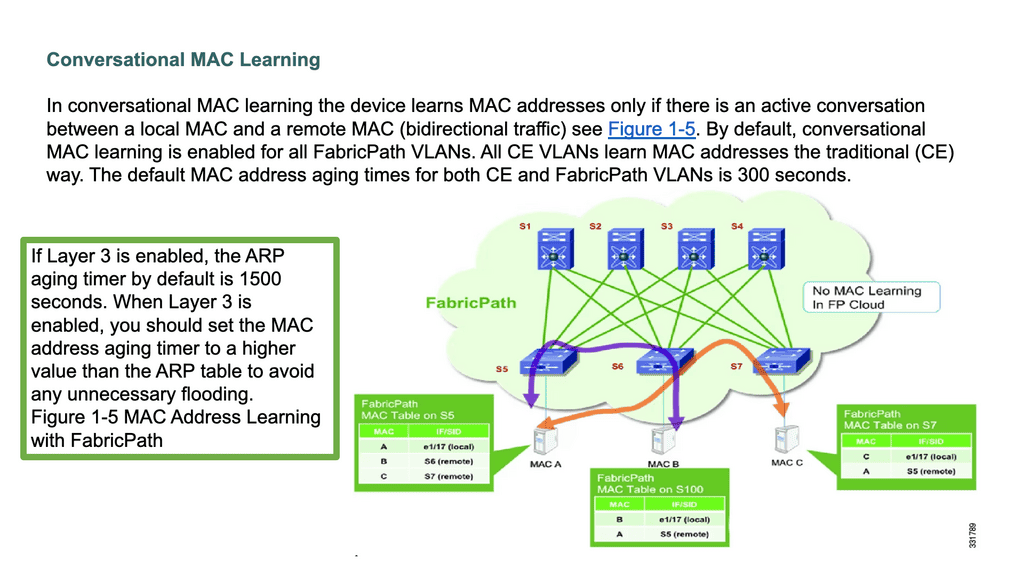
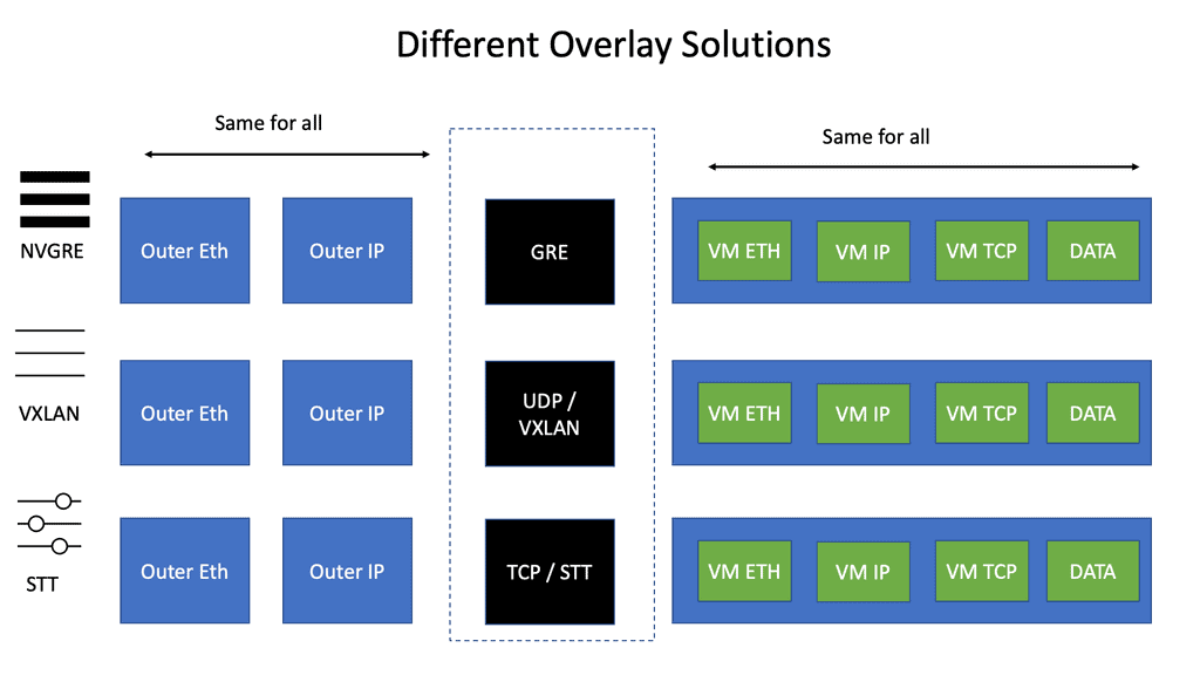
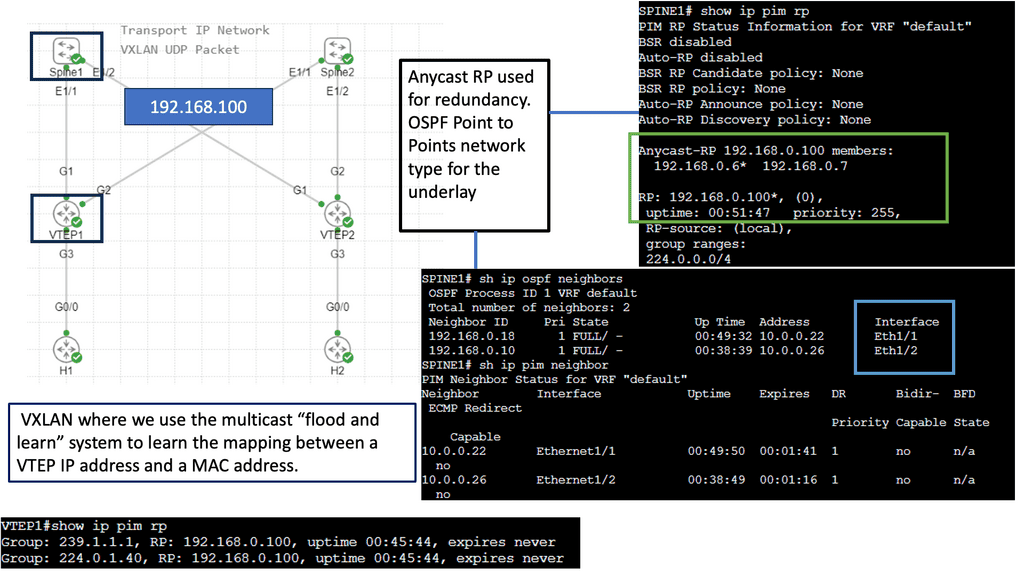
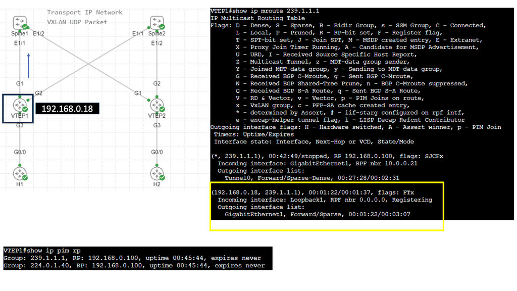
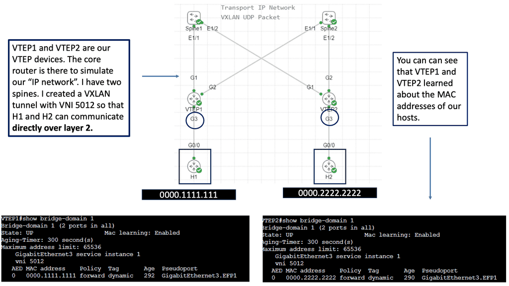
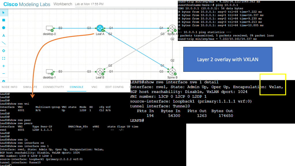
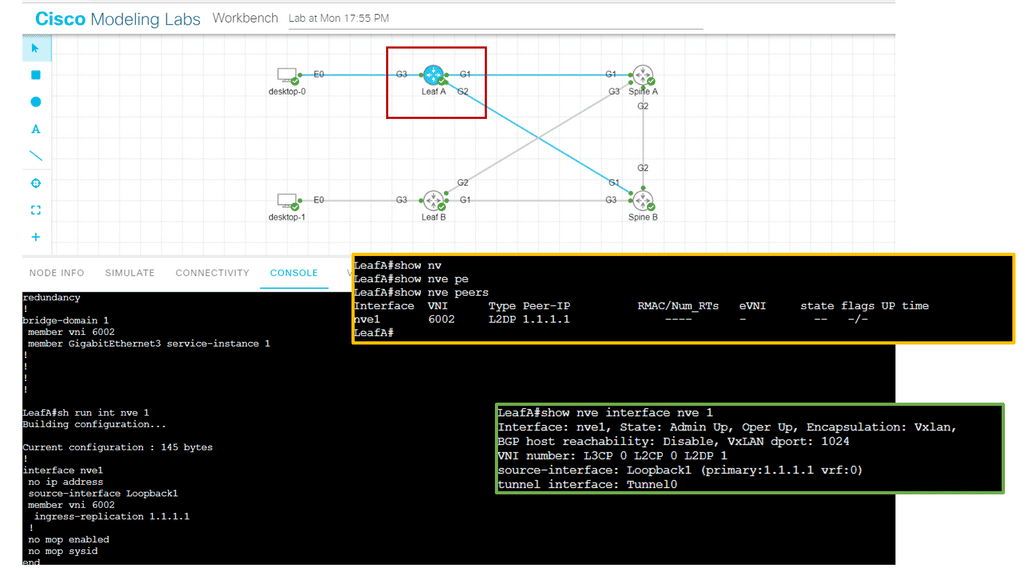
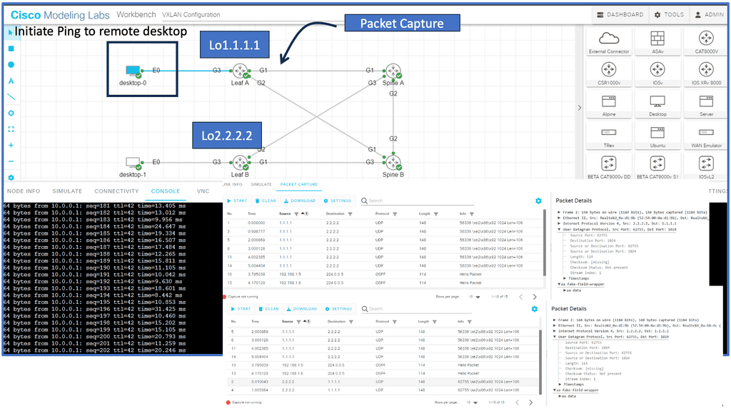
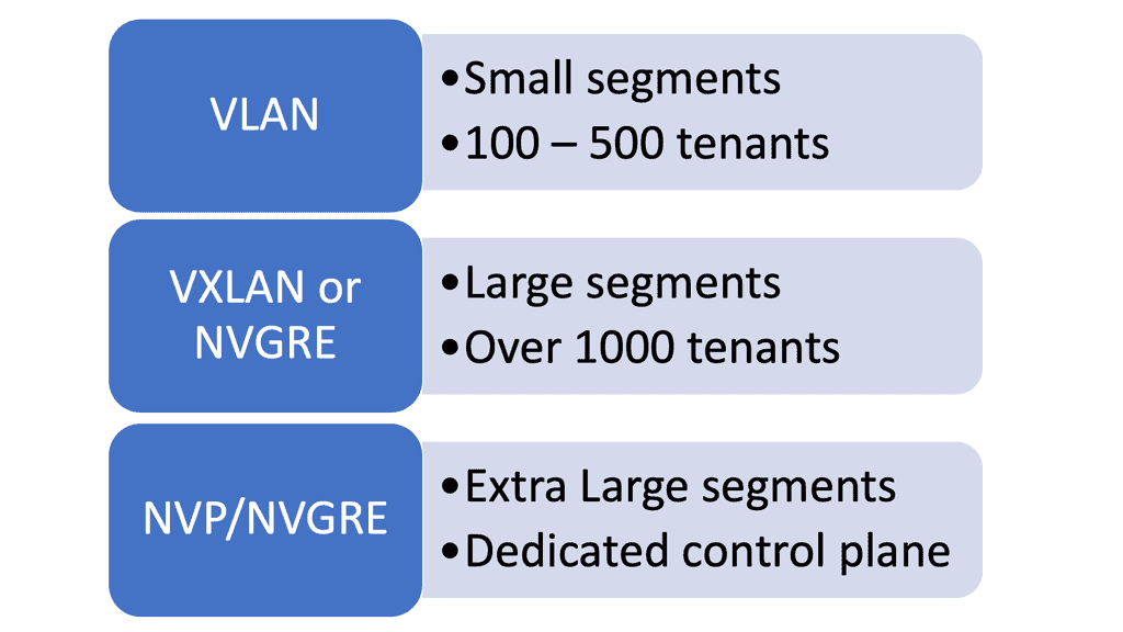
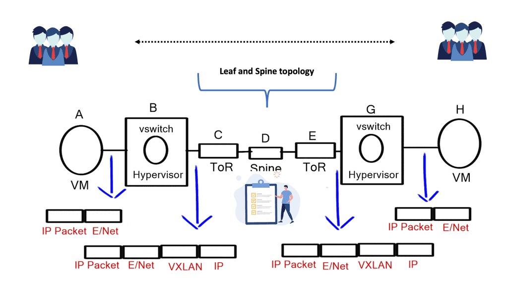
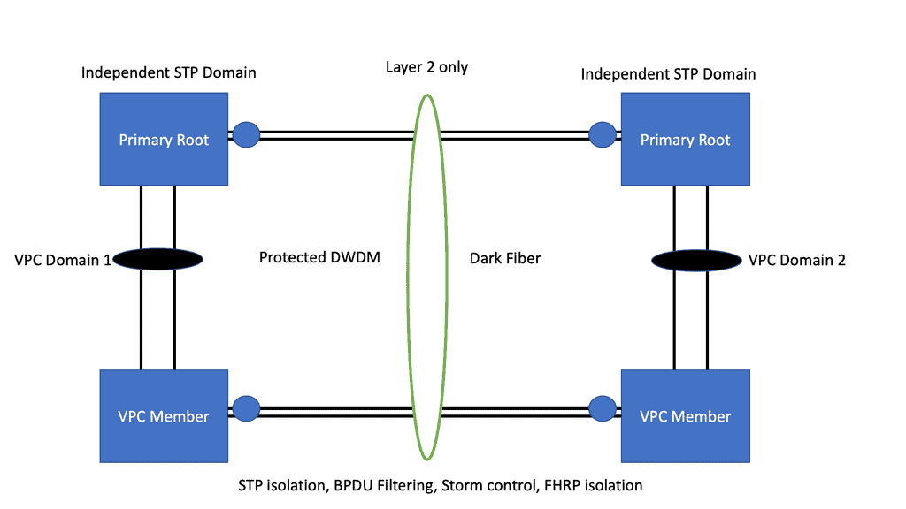
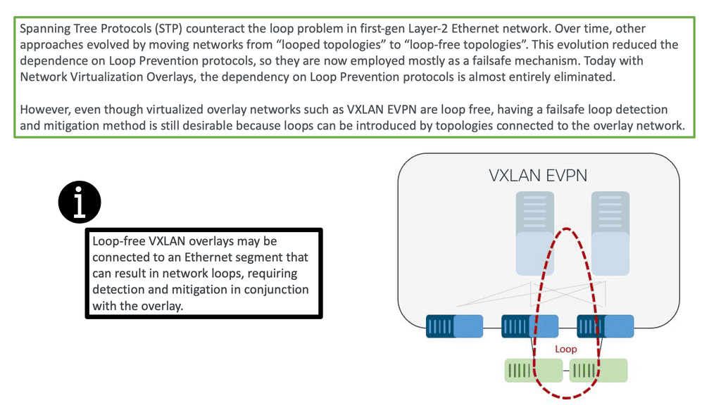
The advent of VXLAN
With the advent of VXLAN, which allows up to 16 million logical entities, the benefits of SDN should not be purely associated with overcoming VLAN scaling issues. VXLAN already does an excellent job with this. It does make sense to deploy a centralized control plane in smaller independent islands; in my view, it should be at the edge of the network for security and policy enforcement roles. Using Openflow on one or more remote devices is easy to implement and scale.
It also decreases the impact of controller failure. If a controller fails and its sole job is implementing packet filters when a new user connects to the network, the only affecting element is that the new user cannot connect. If the controller is responsible for core changes, you may have interesting results with a failure. New users not being able to connect is bad, but losing your entire fabric is not as bad.
A traditional networking device runs all the control and data plane functions. The control plane, usually implemented in the central CPU or the supervisor module, downloads the forwarding instructions into the data plane structures. Every vendor needs communications protocols to bind the two planes together to download forward instructions.
Therefore, all distributed architects need a protocol between control and data plane elements. The protocol binding this communication path for traditional vendor devices is not open-source, and every vendor uses its proprietary protocol (Cisco uses IPC—InterProcess Communication ).
Openflow tries to define a standard protocol between the control plane and the associated data plane. When you think of Openflow, you should relate it to the communication protocol between the traditional supervisors and the line cards. OpenFlow is just a low-level tool.
OpenFlow is a control plane ( controller ) to data plane ( OpenFlow enabled device ) protocol that allows the control plane to modify forwarding entries in the data plane. It enables SDN to separate the data and control planes.

Proactive versus reactive flow setup
OpenFlow operations have two types of flow setups: Proactive and Reactive.
With Proactive, the controller can populate the flow tables ahead of time, similar to a typical routing. However, the packet-in event never occurs by pre-defining your flows and actions ahead of time in the switch’s flow tables. The result is all packets are forwarded at line rate. With Reactive, the network devices react to traffic, consult the OpenFlow controller, and create a rule in the flow table based on the instruction. The problem with this approach is that there can be many CPU hits.
The following table outlines the critical points for each type of flow setup:
Proactive flow setup | Reactive flow setup |
Works well when the controller is emulating BGP or OSPF. | Used when no one can predict when and where a new MAC address will appear. |
The controller must first discover the entire topology. | Punts unknown packets to the controller. Many CPU hits. |
Discover endpoints ( MAC addresses, IP addresses, and IP subnets ) | Compute forwarding paths on demand. Not off the box computation. |
Compute off the box optimal forwarding. | Install flow entries based on actual traffic. |
Download flow entries to the data plane switches. | Has many scalability concerns such as packet punting rate. |
No data plane controller involvement with the exceptions of ARP and MAC learning. Line-rate performance. | Not a recommended setup. |
Hop-by-hop versus path-based forwarding
The following table illustrates the key points for the two types of forwarding methods used by OpenFlow: hop-by-hop forwarding and path-based forwarding:
Hop-by-hop Forwarding | Path-based Forwarding |
Similar to traditional IP Forwarding. | Similar to MPLS. |
Installs identical flows on each switch on the data path. | Map flows to paths on ingress switches and assigns user traffic to paths at the edge node |
Scalability concerns relating to flow updates after a change in topology. | Compute paths across the network and installs end-to-end path-forwarding entries. |
Significant overhead in large-scale networks. | Works better than hop-by-hop forwarding in large-scale networks. |
FIB update challenges. Convergence time. | Core switches don’t have to support the same granular functionality as edge switches. |
Obviously, with any controller, the controller is a lucrative target for attack. Anyone who knows you are using a controller-based network will try to attack the controller and its control plane. The attacker may attempt to intercept the controller-to-switch communication and replace it with its commands, essentially attacking the control plane with whatever means they like.
An attacker may also try to insert a malformed packet or some other type of unknown packet into the controller ( fuzzing attack ), exploiting bugs in the controller and causing the controller to crash.
Fuzzing attacks can be carried out with application scanning software such as Burp Suite. It attempts to manipulate data in a particular way, breaking the application.
The best way to tighten security is to encrypt switch-to-controller communications with SSL and self-signed certificates to authenticate the switch and controller. It would also be best to minimize interaction with the data plane, except for ARP and MAC learning.
To prevent denial-of-service attacks on the controller, you can use Control Plane Policing ( CoPP ) on Ingress to avoid overloading the switch and the controller. Currently, NEC is the only vendor implementing CoPP.
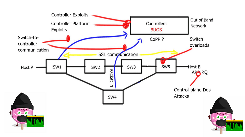
The Hybrid deployment model is helpful from a security perspective. For example, you can group specific ports or VLANs to OpenFlow and other ports or VLANs to traditional forwarding, then use traditional forwarding to communicate with the OpenFlow controller.
Software-defined networking or traditional routing protocols?
The move to a Software-Defined Networking architecture has clear advantages. It’s agile and can react quickly to business needs, such as new product development. For businesses to succeed, they must have software that continues evolving.
Otherwise, your customers and staff may lose interest in your product and service. The following table displays the advantages and disadvantages of the existing routing protocol control architecture.
+Reliable and well known. | -Non-standard Forwarding models. Destination-only and not load-aware metrics** |
+Proven with 20 plus years field experience. | -Loosely coupled. |
+Deterministic and predictable. | -Lacks end-to-end transactional consistency and visibility. |
+Self-Healing. Traffic can reroute around a failed node or link. | -Limited Topology discovery and extraction. Basic neighbor and topology tables. |
+Autonomous. | -Lacks the ability to change existing control plane protocol behavior. |
+Scalable. | -Lacks the ability to introduce new control plane protocols. |
+Plenty of learning and reading materials. |
** Basic EIGRP IETF originally proposed an Energy-Aware Control Plane, but the IETF later removed this.
Software-Defined Networking: Use Cases
Edge Security policy enforcement at the network edge. | Authenticate users or VMs and deploy per-user ACL before connecting a user to the network. |
Custom routing and online TE. | The ability to route on a variety of business metrics aka routing for dollars. Allowing you to override the default routing behavior. |
Custom traffic processing. | For analytics and encryption. |
Programmable SPAN ports | Use Openflow entries to mirror selected traffic to the SPAN port. |
DoS traffic blackholing & distributed DoS prevention. | Block DoS traffic as close to the source as possible with more selective traffic targeting than the original RTBH approach**. The traffic blocking is implemented in OpenFlow switches. Higher performance with significantly lower costs. |
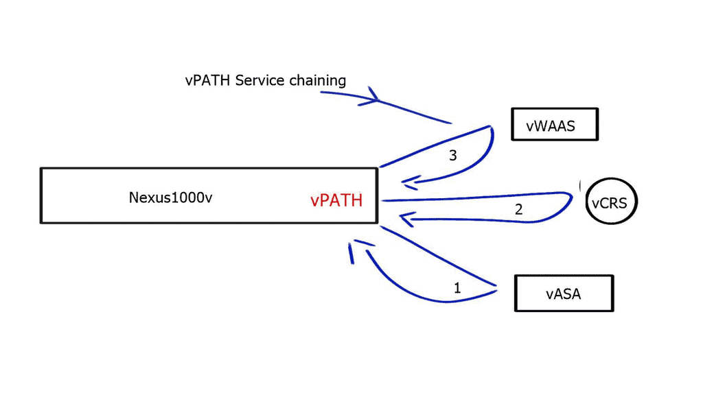
Traffic redirection and service insertion. | Redirect a subset of traffic to network appliances and install redirection flow entries wherever needed. |
Network Monitoring. | The controller is the authoritative source of information on network topology and Forwarding paths. |
Scale-Out Load Balancing. | Punt new flows to the Openflow controller and install per-session entries throughout the network. |
IPS Scale-Out. | OpenFlow is used to distribute the load to multiple IDS appliances. |
**Remote-Triggered Black Hole: RTBH refers to installing a host route to a bogus IP address ( RTBH address ) pointing to NULL interfaces on all routers. BGP is used to advertise the host routes to other BGP peers of the attacked hosts, with the next hop pointing to the RTBH address, and it is mainly automated in ISP environments.
SDN deployment models
Guidelines:
- Start with small deployments away from the mission-critical production path, i.e., the Core. Ideally, start with device or service provisioning systems.
- Start at the Edge and slowly integrate with the Core. Minimize the risk and blast radius. Start with packet filters at the Edge and tasks that can be easily automated ( VLANs ).
- Integrate new technology with the existing network.
- Gradually increase scale and gain trust. Experience is key.
- Have the controller in a protected out-of-band network with SSL connectivity to the switches.
There are 4 different models for OpenFlow deployment, and the following sections list the key points of each model.
Native OpenFlow
- They are commonly used for Greenfield deployments.
- The controller performs all the intelligent functions.
- The forwarding plane switches have little intelligence and solely perform packet forwarding.
- The white box switches need IP connectivity to the controller for the OpenFlow control sessions. If you are forced to use an in-band network for this communication path using an isolated VLAN with STP, you should use an out-of-band network.
- Fast convergence techniques such as BFD may be challenging to use with a central controller.
- Many people believe that this approach does not work for a regular company. Companies implementing native OpenFlow, such as Google, have the time and resources to reinvent the wheel when implementing a new control-plane protocol ( OpenFlow ).
Native OpenFlow with Extensions
- Some control plane functions are handled from the centralized controller to the forwarding plane switches. For example, the OpenFlow-enabled switches could load balancing across multiple links without the controller’s previous decision. You could also run STP, LACP, or ARP locally on the switch without interaction with the controller. This approach is helpful if you lose connectivity to the controller. If the low-level switches perform certain controller functions, packet forwarding will continue in the event of failure.
- The local switches should support the specific OpenFlow extensions that let them perform functions on the controller’s behalf.
Hybrid ( Ships in the night )
- This approach is used where OpenFlow runs in parallel with the production network.
- The same network box is controlled by existing on-box and off-box control planes ( OpenFlow).
- Suitable for pilot deployment models as switches still run traditional control plane protocols.
- The Openflow controller manages only specific VLANs or ports on the network.
- The big challenge is determining and investigating the conflict-free sharing of forwarding plane resources across multiple control planes.
Integrated OpenFlow
- OpenFlow classifiers and forwarding entries are integrated with the existing control plane. For example, Juniper’s OpenFlow model follows this mode of operation where OpenFlow static routes can be redistributed into the other routing protocols.
- No need for a new control plane.
- No need to replace all forwarding hardware
- It is the most practical approach as long as the vendor supports it.
Closing Points on OpenFlow
OpenFlow is a communication protocol that provides access to the forwarding plane of a network switch or router over the network. It was initially developed at Stanford University and has since been embraced by the Open Networking Foundation (ONF) as a core component of SDN. OpenFlow allows network administrators to program the control plane, enabling them to direct how packets are forwarded through the network. This decoupling of the control and data planes is what empowers SDN to offer more dynamic and flexible network management.
The architecture of OpenFlow is quite straightforward yet powerful. It consists of three main components: the controller, the switch, and the protocol itself. The controller is the brains of the operation, managing network traffic by sending instructions to OpenFlow-enabled switches. These switches, in turn, execute the instructions received, altering the flow of network data accordingly. This setup allows for centralized network control, offering unprecedented levels of automation and agility.
**Advantages of OpenFlow**
OpenFlow brings several critical advantages to network management and control:
1. Flexibility and Programmability: With OpenFlow, network administrators can dynamically reconfigure the behavior of network devices, allowing for greater adaptability to changing network requirements.
2. Centralized Control: By centralizing control in a single controller, network administrators gain a holistic view of the network, simplifying management and troubleshooting processes.
3. Innovation and Experimentation: OpenFlow enables researchers and developers to experiment with new network protocols and applications, fostering innovation in the networking industry.
4. Scalability: OpenFlow’s centralized control architecture provides the scalability needed to manage large-scale networks efficiently.
**Implications for Network Control**
OpenFlow has significant implications for network control, paving the way for new possibilities in network management:
1. Software-Defined Networking (SDN): OpenFlow is a critical component of the broader concept of SDN, which aims to decouple network control from the underlying hardware, providing a more flexible and programmable infrastructure.
2. Network Virtualization: OpenFlow facilitates network virtualization, allowing multiple virtual networks to coexist on a single physical infrastructure.
3. Traffic Engineering: By controlling the flow of packets at a granular level, OpenFlow enables advanced traffic engineering techniques, optimizing network performance and resource utilization.
OpenFlow represents a paradigm shift in network control, offering a more flexible, scalable, and programmable approach to managing networks. By separating the control and data planes, OpenFlow empowers network administrators to have fine-grained control over network behavior, improving efficiency, innovation, and adaptability. As the networking industry continues to evolve, OpenFlow and its related technologies will undoubtedly play a crucial role in shaping the future of network management.