LISP Control and Data Plane
The networking landscape has undergone significant transformations over the years, with the need for efficient and scalable routing protocols becoming increasingly crucial. In this blog post, we will delve into the world of LISP (Locator/ID Separation Protocol) and explore its control plane, shedding light on its advantages to modern networks.
LISP, developed by the Internet Engineering Task Force (IETF), is a protocol that separates the location and identity of network devices. It provides a scalable solution for routing by decoupling the IP address (identity) from a device's physical location (locator). The control plane of LISP plays a vital role in managing and distributing the mapping information required for efficient and effective routing.
We need a method to separate identity from location that offers many benefits. However, a single address field for identifying a device and determining where it is topologically located is not an optimum approach and presents many challenges with host mobility.
Understanding the Control Plane: The control plane in LISP is responsible for managing the mappings between endpoint identifiers (EIDs) and routing locators (RLOCs). It enables efficient and scalable routing by separating the identity of a device from its location. By leveraging the distributed mapping system, control plane operations ensure seamless communication across networks.
Unraveling the Data Plane: The data plane is where the actual packet forwarding occurs in LISP. It relies on encapsulation and decapsulation techniques to encapsulate the original IP packet within a LISP header. The encapsulated packet is then routed through the network based on the EID-to-RLOC mapping obtained from the control plane. The data plane plays a vital role in maintaining network efficiency and enabling seamless mobility.
The LISP control and data plane offer several advantages for modern networks. Firstly, it enhances scalability by reducing the size of routing tables and simplifying network architecture. Secondly, LISP provides improved mobility support, allowing devices to move without changing their IP addresses. This feature is particularly beneficial for mobile networks and IoT deployments. Lastly, the control and data plane separation enables more efficient traffic engineering and network optimization.
Implementing LISP control and data plane requires a combination of software and hardware components. Several vendors offer LISP-enabled routers and switches, making it easier to adopt this protocol in existing network infrastructures. Additionally, various open-source software implementations are available, allowing network administrators to experiment and deploy LISP in a flexible manner.
Matt Conran
Highlights: LISP Control and Data Plane
**Understanding the Data Plane**
The data plane, also known as the forwarding plane, is responsible for the actual transmission of data packets from source to destination. In LISP, the data plane leverages the encapsulation of packets, wherein the original IP packets are wrapped with additional headers. This encapsulation allows for the separation of endpoint identifiers (EIDs) from routing locators (RLOCs), facilitating seamless data flow across diverse network environments. The data plane’s efficiency in LISP is characterized by reduced routing table sizes and enhanced routing flexibility.
**Exploring the Control Plane**
On the other side of LISP’s architecture lies the control plane, which is pivotal in maintaining the mapping between EIDs and RLOCs. This plane is responsible for managing and distributing these mappings across the network, ensuring that data packets are directed to their correct destinations. The control plane operates through a distributed database system, often referred to as the Mapping System, which efficiently handles dynamic and scalable network changes. By decoupling the control plane from the data plane, LISP allows for more agile and adaptive network configurations.
**Interplay Between Data and Control Planes**
The interaction between the data and control planes in LISP is a dance of coordination and precision. The control plane provides the necessary mappings that guide the data plane in its forwarding decisions. This synchronization ensures that data packets are encapsulated with the correct RLOCs based on the up-to-date mappings, optimizing the routing paths and minimizing latency. The interplay between these two planes allows LISP to support features like traffic engineering, multihoming, and seamless mobility across networks, making it a versatile tool in network architecture.
**Benefits of LISP’s Dual-Plane Architecture**
LISP’s architecture, with its distinct separation of data and control planes, offers several advantages. This dual-plane model enhances scalability by reducing the size of routing tables and simplifying network configurations. It also improves network agility, allowing for quick adaptations to changes in network topology or traffic patterns. Additionally, LISP supports advanced functions like virtual network overlays and secure data transmission, making it an attractive solution for modern, complex networking environments.
LISP Key Considerations:
- The LISP Protocol
The LISP protocol offers an architecture that provides seamless ingress traffic engineering and move detection without any DNS changes or agents on the host. A design that LISP can use would be active data center design. A vital concept of the LISP protocol is that end hosts operate similarly. Hosts’ IP addresses for tracking sockets and connections and sending and receiving packets do not change.
- LISP Routing
LISP attempts to establish communication among endpoint devices. Endpoints in IP networks are called IP hosts, and these hosts are typically not LISP-enabled, so each endpoint originates packets with a single IPv4 or IPv6 header to another endpoint. Many endpoints exist, including servers (physical or virtual), workstations, tablets, smartphones, printers, IP phones, and telepresence devices. EIDs are LISP addresses assigned to endpoints.
- EID – Globally Unique
The EID must be globally unique when communicating on the Internet, just like IP addresses. To be reachable from the public IP space, private addresses must be translated to global addresses through network address translation (NAT). Like any other routing database on the Internet, the global LISP mapping database cannot be populated with private addresses. In contrast, the global LISP mapping database can identify entries as members of different virtual private networks (VPNs).
BGP/MPLS Internet Protocol (IP) VPN network routers have separate virtual routing and forwarding (VRF) tables for each VPN; in the same vein, LISP can be used to create private networks and to have an Internet router with separate routing tables (VRFs) for internet routes and private addresses. In many cases, private EID addresses do not have to be routable over the public Internet when using a dedicated private LISP mapping database. With LISP, private deployments may use the public Internet as an underlay to create VPNs, leveraging the public Internet for transport.
Before you proceed, you may find the following useful for pre-information:
LISP Control and Data Plane
LISP: An IP overlay solution
LISP is an IP overlay solution that keeps the same semantics for IPv4 and IPv6 packet headers but operates two separate namespaces: one to specify the location and the other to determine the identity. A LISP packet has an inner IP header, which, like the headers of traditional IP packets, is for communicating endpoint to endpoint.
This would be from a particular source to a destination address. Then we have the outer IP header that provides the location to which the endpoint attaches. The outer IP headers are also IP addresses.
Therefore, if an endpoint changes location, its IP address remains unchanged. It is the outer header that consistently gets the packet to the location of the endpoint. The endpoint identifier (EID) address is mapped to a router that the endpoint sits behind, which is understood as the routing locator (RLOC) in LISP terminology.
**Benefits of LISP Control Plane**
1. Scalability: LISP’s control plane offers scalability advantages by reducing the size of the routing tables. With LISP, the mapping system maintains only the necessary information, allowing for efficient routing in large networks.
2. Mobility: The control plane of LISP enables seamless mobility as devices move across different locations. By separating the identity and locator, LISP ensures that devices maintain connectivity even when their physical location changes, reducing disruptions and enhancing network flexibility.
3. Traffic Engineering: LISP’s control plane allows for intelligent traffic engineering, enabling network operators to optimize traffic flow based on specific requirements. By leveraging the mapping information, routing decisions can be made dynamically, leading to efficient utilization of network resources.
4. Security: The LISP control plane offers enhanced security features. By separating the identity and locator, LISP helps protect the privacy of devices, making it harder for attackers to track or target specific devices. Additionally, LISP supports authentication mechanisms, ensuring the integrity and authenticity of the mapping information.
Implementing LISP Control Plane:
Several components are required to implement the LISP control plane, including the mapping system, the encapsulation mechanism, and the LISP routers. The mapping system is responsible for storing and distributing the mapping information, while the encapsulation mechanism ensures the separation of identity and locator. LISP routers play a crucial role in forwarding traffic based on the mapping information received from the control plane.
**Real-World Use Cases**
LISP control plane has found applications in various real-world scenarios, including:
1. Data Centers: LISP helps optimize traffic flow within data centers, facilitating efficient load balancing and reducing latency.
2. Internet Service Providers (ISPs): The LISP control plane enables ISPs to enhance their routing infrastructure, improving scalability and mobility support for their customers.
3. Internet of Things (IoT): As the number of connected devices continues to grow, the LISP control plane offers a scalable solution for managing the routing of IoT devices, ensuring seamless connectivity even as devices move.
Control Plane vs Data Plane
The LISP data plane

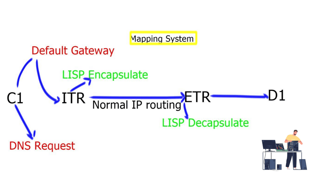
- Client C1 is located in a remote LISP-enabled site and wants to open a TCP connection with D1, a server deployed in a LISP-enabled Data Center. C1 queries through DNS the IP address of D1 and an A/AAAA record is returned. The address returned is the destination Endpoint Identifier ( EID ), and it’s non-routable. EIDs are IP addresses assigned to hosts. Client C1 realizes this is not an address on its local subnet and steers the traffic to its default gateway, a LISP-enabled device. This triggers the LISP control-plane activity.
- The LISP control plane is triggered only if the lookup produces no results or if the only available match is a default route. This means that a Map-Request ( from ITR to the Mapping system ) is sent only when the destination is not found.
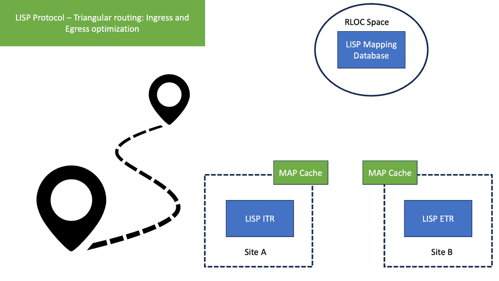
- The ITR receives its EID-to-RLOC mapping from the mapping system and updates its local map-cache, which previously did not contain the mapping. The local map cache can be used for future communications between these endpoints.
- The destination EID will be mapped to several RLOC ( Routing Locator ), which will identify the ( Egress Tunnel Router ) ETRs at the remote Data Center site. Each entry has associated priorities and weights with loading balance, influencing inbound traffic towards the RLOC address space. The specific RLOC is selected per-flow based on the 5-tuple hashing of the original client’s IP packet.
- Once the controls are in place, the ITR performs LISP encapsulation on the original packets and forwards the LISP encapsulated packet to one ( two or more if load balancing is used ) of the RLOCs of the Data Center ETRs. RLOC prefixes are routable addresses. Destination ETR receives the packet, decapsulates it, and sends it towards the destination EID.
LISP control plane

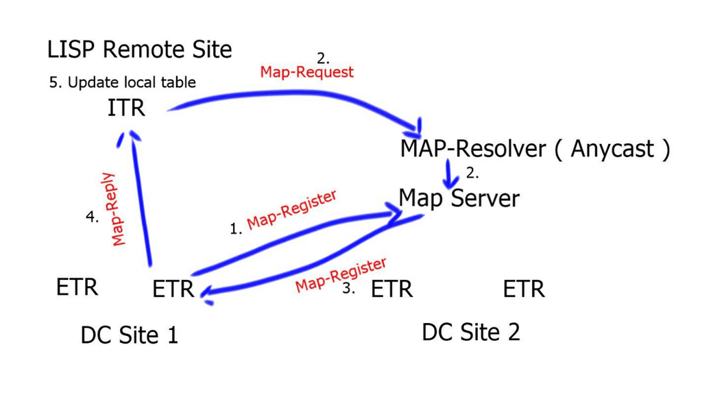
- The destination ETRs register their non-routable EIDs to the Map-Server using a Map-Register message. This is done every 60 seconds.If the ITR does not have a local mapping for the remote EID-RLOC mapping, it will send a Map-Request message to the Map-Resolver. Map-Requests should be rate-limited to avoid denial of service attacks.
- The Map-Resolver then forwards the request to the authoritative Map-Server. The Map-Resolver and Map-Server could be the same device. The Map resolver could also be an anycast address.
- The Map-Server then forwards the request to the last registered ETR. The ETR looks at the destination of the Map-Request and compares it to its configured EID-to-RLOC database. A match triggers the ETR to directly reply to the ITR with a Map-Reply containing the requested mapping information. Map-Replies are sent using the underlying routing system topology. On the other hand, if there is no match, the Map-Request is dropped.
- When the ITR receives the Map-Reply containing the mapping information, it will update its local EID-to-RLOC map cache. All subsequent flows will go forward without the integration of the mapping systems.
Summary: LISP Control and Data Plane
LISP, which stands for Locator/Identifier Separation Protocol, is a networking architecture that separates the device’s identity (identifier) from its location (locator). This innovative approach benefits network scalability, mobility, and security. In this blog post, we will dive into the details of the LISP control and data plane and explore how they work together to provide efficient and flexible networking solutions.
Understanding the LISP Control Plane
The control plane in LISP is responsible for managing the mapping between the device’s identifier and locator. It handles the registration process, where a device registers its identifier and locator information with a Map-Server. The control plane also maintains the mapping database, which stores the current mappings. This section will delve into the workings of the LISP control plane and discuss its essential components and protocols.
Exploring the LISP Data Plane
While the control plane handles the mapping information, the data plane in LISP is responsible for the actual forwarding of traffic. It ensures that packets are efficiently routed to their intended destination by leveraging the mappings provided by the control plane. This section will explore the LISP data plane, including its encapsulation mechanisms and how it facilitates seamless communication across different networks.
Benefits of the LISP Control and Data Plane Integration
The true power of LISP lies in the seamless integration of its control and data planes. By separating the identity and location, LISP enables improved scalability and mobility. This section will discuss the advantages of this integration, such as simplified network management, enhanced load balancing, and efficient traffic engineering.
Conclusion:
In conclusion, the LISP control and data plane form a harmonious duo that revolutionizes networking architectures. The control plane efficiently manages the mapping between the identifier and locator, while the data plane ensures optimal packet forwarding. Their integration brings numerous benefits, paving the way for scalable, mobile, and secure networks. Whether you’re an aspiring network engineer or a seasoned professional, understanding the intricacies of the LISP control and data plane is crucial in today’s rapidly evolving networking landscape.
- DMVPN - May 20, 2023
- Computer Networking: Building a Strong Foundation for Success - April 7, 2023
- eBOOK – SASE Capabilities - April 6, 2023


