Dead peer detection

Dead Peer Detection

Dead Peer Dedection

In today's interconnected world, network security is of paramount importance. Network administrators constantly strive to ensure the integrity and reliability of their networks. One crucial aspect of network security is Dead Peer Detection (DPD), a vital mechanism in monitoring and managing network connectivity. In this blog post, we will delve into the concept of Dead Peer Detection, its significance, and its impact on network security and reliability.

Dead Peer Detection is a protocol used in Virtual Private Networks (VPNs) and Internet Protocol Security (IPsec) implementations to detect the availability and reachability of remote peers. It is designed to identify if a remote peer has become unresponsive or has experienced a failure, making it a crucial mechanism for maintaining secure and reliable network connections.

DPD plays a vital role in various networking protocols such as IPsec and VPNs. It helps to detect when a peer has become unresponsive due to network failures, crashes, or other unforeseen circumstances. By identifying inactive peers, DPD enables the network to take appropriate actions to maintain reliable connections and optimize network performance.

To implement DPD effectively, network administrators need to configure appropriate DPD parameters and thresholds. These include setting the interval between control message exchanges, defining the number of missed messages before considering a peer as "dead," and specifying the actions to be taken upon detecting a dead peer. Proper configuration ensures timely and accurate detection of unresponsive peers.

While DPD provides valuable benefits, it is essential to be aware of potential challenges and considerations. False positives, where a peer is mistakenly identified as dead, can disrupt network connectivity unnecessarily. On the other hand, false negatives, where a genuinely inactive peer goes undetected, can lead to prolonged network disruptions. Careful configuration and monitoring are necessary to strike the right balance.

To maximize the effectiveness of DPD, several best practices can be followed. Regularly updating and patching network devices and software helps address potential vulnerabilities that may impact DPD functionality. Additionally, monitoring DPD logs and alerts allows for proactive identification and resolution of issues, ensuring the ongoing reliability of network connections.

Dead Peer Detection is a critical component of network communication and security. By detecting unresponsive peers, it enables networks to maintain reliable connections and optimize performance. However, proper configuration, monitoring, and adherence to best practices are crucial for its successful implementation. Understanding the intricacies of DPD empowers network administrators to enhance network reliability and overall user experience.

Highlights: Dead Peer Dedection

What is Dead Peer Detection?

– In the world of networking, maintaining a stable and reliable connection is paramount. Dead Peer Detection (DPD) is a technique used to ensure that the connections between peers, or nodes, in a network are active and functioning correctly. This process involves monitoring the state of these connections and determining whether any peer has become unresponsive or “dead.”

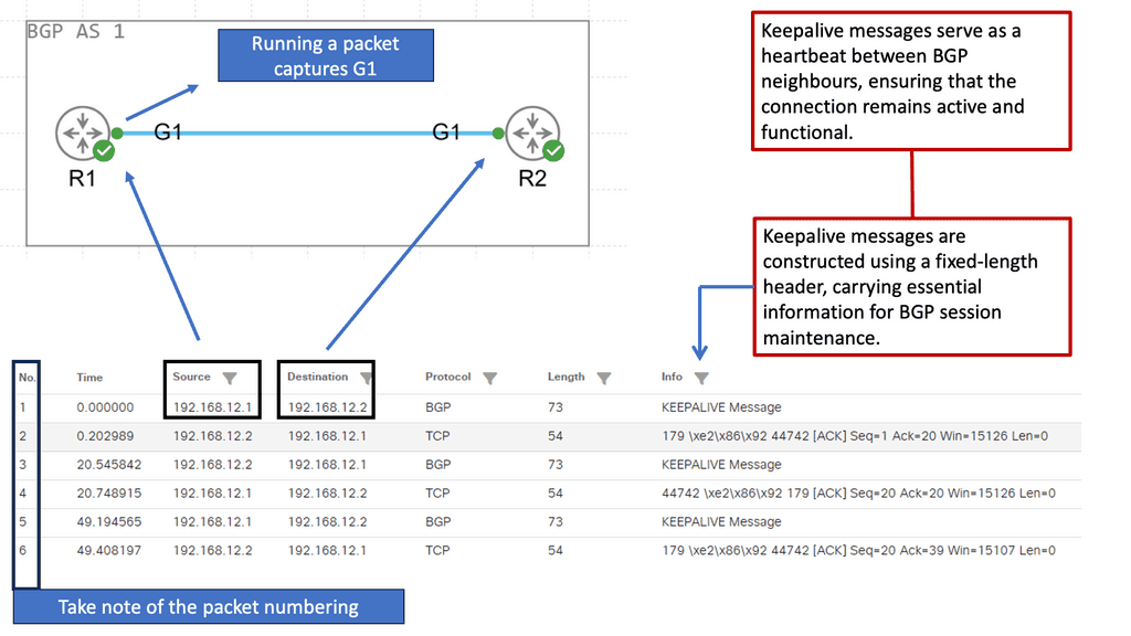
– Dead Peer Detection operates by sending periodic “keepalive” messages between peers. If a peer fails to respond within a specified timeframe, it is marked as potentially dead. This helps in identifying and troubleshooting issues quickly, ensuring that network resources are not wasted on inactive connections. The process can involve different methods such as ICMP (Internet Control Message Protocol) pinging or higher-level protocol-based checks.

– DPD is crucial for maintaining the integrity and efficiency of a network. By identifying inactive or dead peers promptly, network administrators can take corrective actions, such as rerouting traffic or resetting connections, to maintain optimal performance. This is especially important in environments where uptime and reliability are critical, such as in financial services, healthcare, or large-scale cloud infrastructures.

When implementing Dead Peer Detection, it is important to consider the following best practices:

– **Frequency of Checks**: Balance is key. Too frequent checks may lead to unnecessary network load, while infrequent checks might delay the detection of dead peers.

– **Timeout Settings**: Configure timeout settings based on the network’s typical latency and performance characteristics to avoid false positives.

– **Scalability**: Ensure that the DPD mechanism can scale with the network’s growth without impacting performance.

Dead Peer Detection Key Points: 

A: ) Dead Peer Detection, commonly abbreviated as DPD, is a mechanism used in network security protocols to monitor the availability of a remote peer in a Virtual Private Network (VPN) connection. By detecting when a peer becomes unresponsive or “dead,” it ensures that the connection remains secure and stable.

B: ) When a VPN connection is established between two peers, DPD periodically sends out heartbeat messages to ensure the remote peer is still active. These heartbeat messages serve as a vital communication link between peers. If a peer fails to respond within a specified timeframe, it is considered unresponsive, and necessary actions can be taken to address the issue.

C: ) Dead Peer Detection plays a pivotal role in maintaining the integrity and security of VPN connections. Detecting unresponsive peers prevents data loss and potential security breaches and ensures uninterrupted communication between network nodes. DPD acts as a proactive measure to mitigate potential risks and vulnerabilities.

Implementing Dead Peer Detection

– Implementing DPD requires configuring the appropriate parameters and thresholds in network devices and security appliances. Network administrators need to carefully determine the optimal DPD settings based on their network infrastructure and requirements. Fine-tuning these settings ensures accurate detection of dead peers while minimizing false positives.

– While Dead Peer Detection offers numerous benefits, certain challenges can arise during its implementation. Issues such as misconfiguration, compatibility problems, or network congestion can affect DPD’s effectiveness. Following best practices, such as proper network monitoring, regular updates, and thorough testing, can help overcome these challenges and maximize DPD’s efficiency.

**The Significance of Dead Peer Detection**

1. Detecting Unresponsive Peers:

DPD detects unresponsive or inactive peers within a VPN or IPsec network. By periodically sending and receiving DPD messages, devices can determine if a remote peer is still active and reachable. If a peer fails to respond within a specified time frame, it is considered dead, and appropriate actions can be taken to ensure network availability.

2. Handling Network Failures:

In network failures, such as link disruptions or device malfunctions, DPD plays a critical role in detecting and resolving these issues. By continuously monitoring the availability of peers, DPD helps network administrators identify and address network failures promptly, minimizing downtime and ensuring uninterrupted network connectivity.

3. Enhancing Network Security:

DPD contributes to network security by detecting potential security breaches. A peer failing to respond to DPD messages could indicate an unauthorized access attempt, a compromised device, or a security vulnerability. DPD helps prevent unauthorized access and potential security threats by promptly identifying and terminating unresponsive or compromised peers.

**Implementing Dead Peer Detection**

To implement Dead Peer Detection effectively, network administrators need to consider the following key factors:

1. DPD Configuration:

Configuring DPD involves setting parameters such as DPD interval, DPD timeout, and number of retries. These settings determine how frequently DPD messages are sent, how long a peer has to respond, and the number of retries before considering a peer dead. The proper configuration ensures optimal network performance and responsiveness.

2. DPD Integration with VPN/IPsec:

DPD is typically integrated into VPN and IPsec implementations to monitor the status of remote peers. Network devices involved in the communication establish DPD sessions and exchange DPD messages to detect peer availability. It is essential to ensure seamless integration of DPD with VPN/IPsec implementations to maximize network security and reliability.

**Best Practices for Dead Peer Detection**

To maximize the effectiveness of DPD, it is advisable to follow these best practices:

1. Configure Reasonable DPD Timers: Setting appropriate DPD timers is crucial to balance timely detection and avoiding false positives. The timers should be configured based on the network environment and the expected responsiveness of the peers.

2. Regularly Update Firmware and Software: It is essential to keep network devices up-to-date with the latest firmware and software patches. This helps address any potential vulnerabilities that attackers attempting to bypass DPD mechanisms could exploit.

3. Monitor DPD Logs: Regularly monitoring DPD logs allows network administrators to identify any recurring patterns of inactive peers. This analysis can provide insights into potential network issues or device failures that require attention.

Dead Peer Detection (DPS) and the shortcoming of IKE Keepalives

Dead Peer Detection (DPD) addresses the shortcomings of IKE keepalives and heartbeats by introducing a more reasonable logic governing message exchange. Essentially, keepalives and heartbeats require an exchange of HELLOs at regular intervals. DPD, on the other hand, allows each peer’s DPD state to be largely independent. Peers can request proof of liveliness whenever needed – not at predetermined intervals. This asynchronous property of DPD exchanges allows fewer messages to be sent, which is how DPD achieves increased scalability.

DPD and IPsec

Dead Peer Detection (DPD) ( IPsec DPD ) is a mechanism whereby a device will send a liveness check to its IKEv2 peer to check that the peer is functioning correctly. It is helpful in high-availability IPsec designs when multiple gateways are available to build VPN tunnels between endpoints. There needs to be a mechanism to detect remote peer failure. IPsec control plane protocol ( IKE ) is based on a connectionless protocol called User Datagram Protocol ( UDP ).

As a result, IKE and IPsec cannot identify the loss of remote peers. IKE does not have a built-in mechanism to detect the availability of remote endpoints. Upon remote-end failure, previously established IKE and IPsec Security Associations ( SA ) remain active until their lifetime expires.

In addition, the lack of peer loss detection may result in network “black holes” as traffic continues to forward until SAs are torn down.
Dead Peer Detection (DPD)
Diagram: Illustrating DPD. Source WordPress site.

**Network Security** 

Dead Peer Detection (DPD) is a network security protocol that detects when a previously connected peer is no longer available. DPD sends periodic messages to network peers and waits for a response. If the peer does not respond to the messages, the Dead Peer Detection IPSec protocol will assume the peer is no longer available and will take appropriate action.

DPD detects when a peer becomes unresponsive or fails to respond to messages. This can be due to several reasons, including the peer being taken offline, a connection issue, or a system crash. When a peer is detected as unresponsive, the DPD protocol will take action, such as disconnecting the peer or removing it from the network.

**DPD protocol**

To ensure a secure connection, the DPD protocol requires peers to authenticate themselves with each other. This helps to verify that the peers are indeed connected and that the messages being sent are legitimate. It also ensures malicious peers cannot disrupt the network by spoofing messages. In addition to authentication, DPD also uses encryption to protect data transmitted between peers. This helps to prevent data from being intercepted or tampered with.

Related: Before you proceed, you may find the following post helpful:

  1. IPv6 Fault Tolerance
  2. Generic Routing Encapsulation
  3. Redundant Links
  4. Routing Convergence 
  5. Routing Control Platform
  6. IP Forwarding
  7. ICMPv6
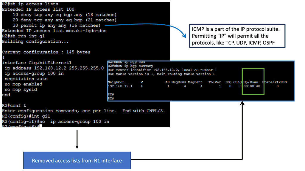
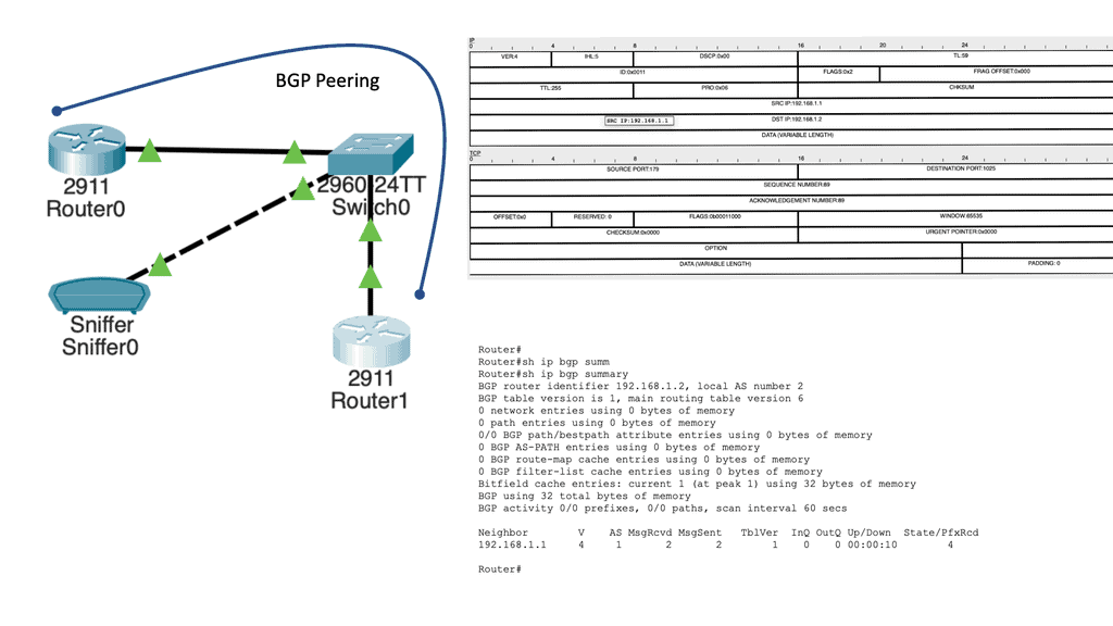
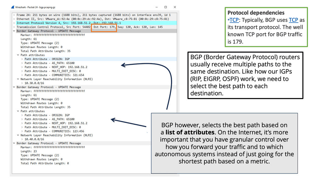
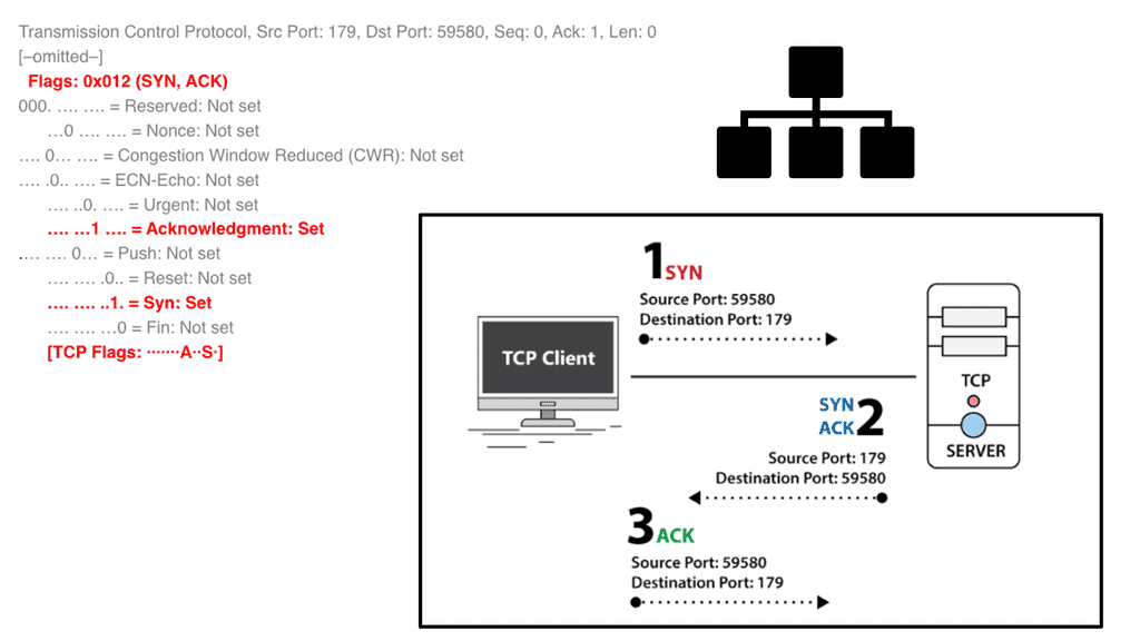
  8. Port 179

Dead Peer Detection

Understanding Dead Peer Detection

DPD serves as a mechanism to detect the availability of a remote peer in a Virtual Private Network (VPN) tunnel. It actively monitors the connection by exchanging heartbeat messages between peers. These messages confirm if the remote peer is still operational, allowing for timely reactions to any potential disruptions.

There are various ways to implement DPD, depending on the VPN protocol used. For instance, in IPsec VPNs, DPD can be configured through parameters such as detection timers and threshold values. Other VPN technologies, such as SSL/TLS, also offer DPD features that can be customized to meet specific requirements.

The advantages of utilizing DPD in VPN networks are numerous. Firstly, it aids in maintaining uninterrupted connectivity by promptly identifying and addressing any peer failures. This ensures that applications relying on the VPN tunnel experience minimal downtime. Additionally, DPD helps optimize network resources by automatically terminating non-responsive tunnels, freeing up valuable resources for other critical operations.

To harness the full potential of DPD, certain best practices should be followed. These include configuring appropriate detection timers and thresholds based on network conditions, regularly monitoring DPD logs for potential issues, and ensuring proper synchronization between peers to avoid false positives.

**A standard VPN**

A VPN permits users to securely expand a private network across an untrusted network. When IPsec VPNs are deployed, traffic is protected to ensure that no one can view the plaintext data; this is accomplished by encryption that provides confidentiality.

IPsec VPN accomplishes this by cryptographic hashing and signing the data exchanged, which provides integrity. Remember that a VPN must be established only with a chosen peer, achieved using mutual authentication.

Please be aware of the distinctions between a VPN using IPsec and a VPN using Multiprotocol Label Switching (MPLS). MPLS uses labels to differentiate traffic. MPLS labels are used to separate traffic, but unlike IPsec, they offer no confidentiality or integrity protection.

Guide: Site-to-site IPsec VPN

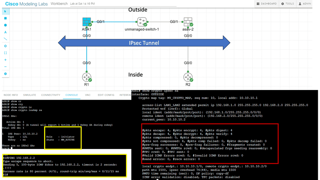
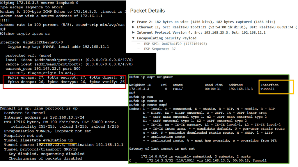
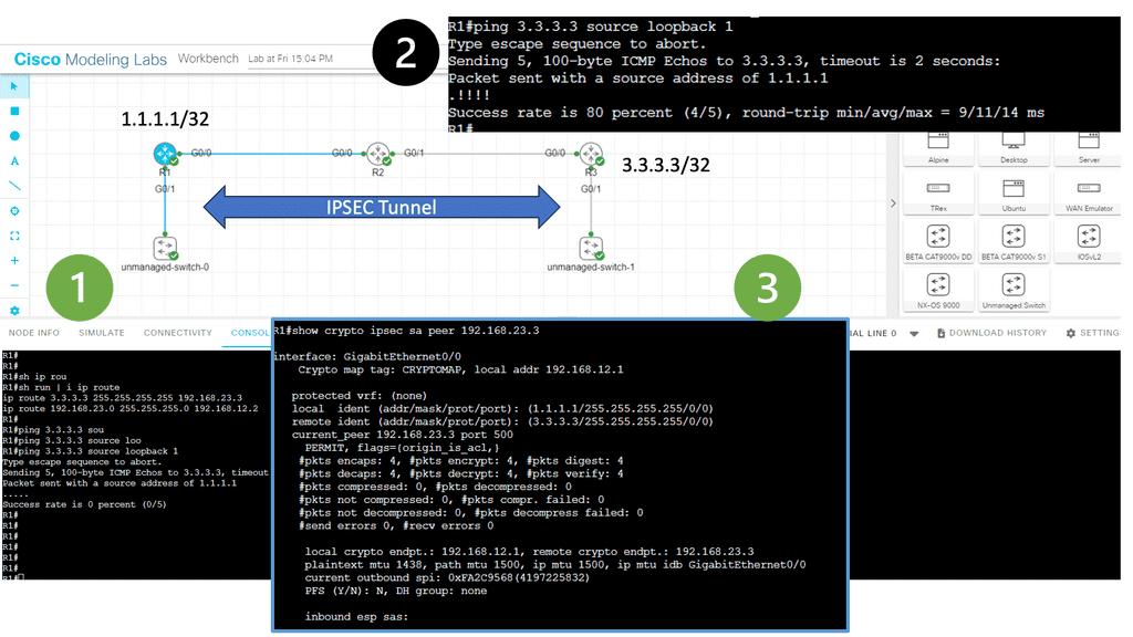
In the following lab, we have three routers. R2 is acting just as an interconnection point. It only has an IP address configuration on its interface. We have two Cisco IOS routers that use IPSec in tunnel mode. This means the original IP packet will be encapsulated in a new IP packet and encrypted before sending it out of the network. For this demonstration, I will be using the following three routers.

R1 and R3 each have a loopback interface behind them with a subnet. We’ll configure the IPsec tunnel between these routers to encrypt traffic from 1.1.1.1/32 to 3.3.3.3/32. Notice in the screenshot below that we can’t ping when the IPsec tunnel is not up. Once the IPsec tunnel is operational, we have reachability between the two peers.
ipsec tunnel
Diagram: IPsec Tunnel

IPsec VPN

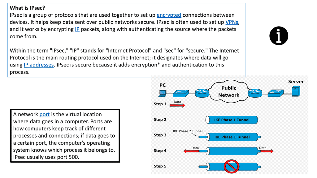
IPSec VPN is a secure virtual private network protocol that encrypts data across different networks. It is used to protect the privacy of data transmitted over the Internet, as well as authenticate the identity of a user or device.

IPSec VPN applies authentication and encryption to the data packets traveling through a network. The authentication ensures that the data comes from a trusted source, while the encryption makes it unreadable to anyone who attempts to intercept the packets.

IPSec VPN is more secure than other VPN protocols, such as Point-to-Point Tunneling Protocol (PPTP) and Layer 2 Tunneling Protocol (L2TP). It can create a secure tunnel between two or more devices, such as computers, smartphones, or tablets. It also makes secure connections with other networks, such as the Internet. The following figure shows a generic IPsec diagram and some IPsec VPN details.
IPsec VPN
Diagram: IPsec VPN. Source Wikimedia.

Example of a VPN solution – DMVPN.

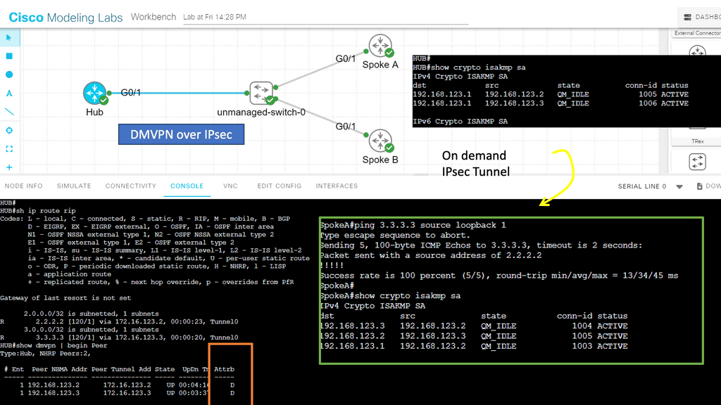
With IPsec-based VPN implementations growing in today’s complex VPN landscape, scalability, simplicity, and ease of deployment have become more critical. DMVPN enhances traditional IPsec deployments by enabling on-demand IPsec tunneling and providing scalable and dynamic IPsec environments. I

IPsec solutions can be deployed with zero-touch using DMVPN, optimizing network performance and bandwidth utilization while reducing latency across the Internet. DMVPN has several DMVPN phases, such as DMVPN phase 1, that allow scaling IPsec VPN networks to offer a large-scale IPsec VPN deployment model.

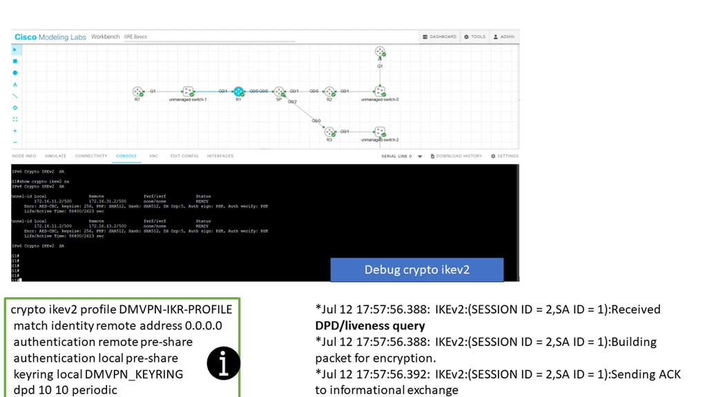
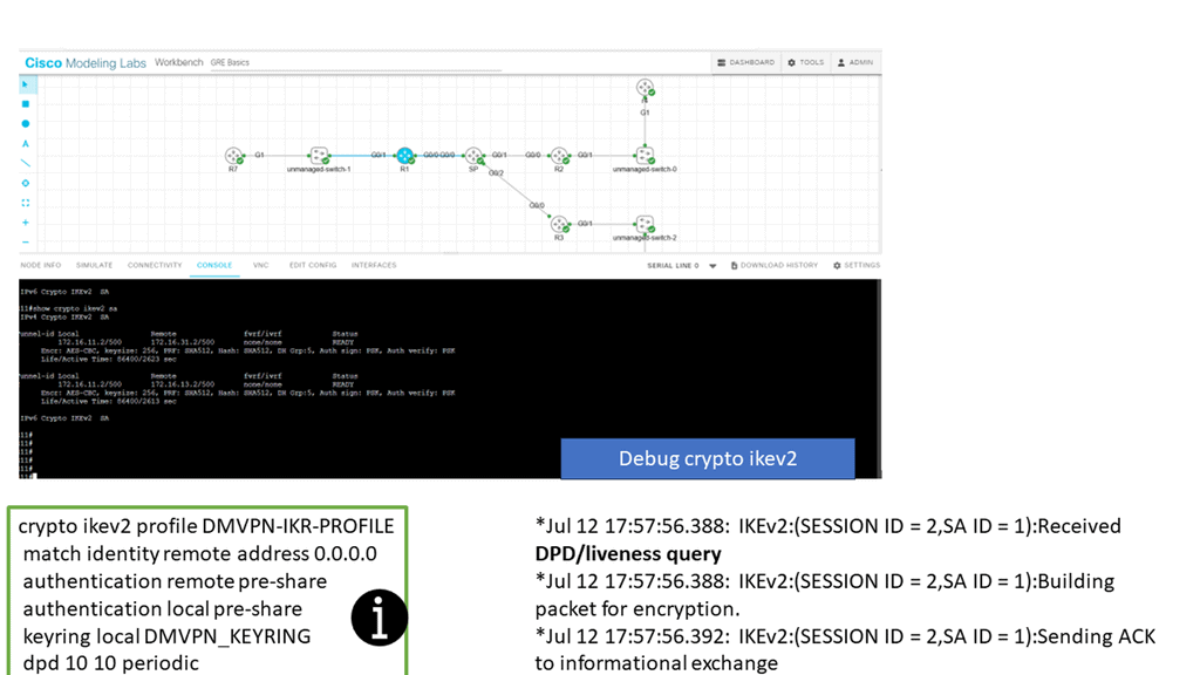
In the screenshot below, we have a DMVPN network. R1 is the Hub, and R2 and R3 are the spokes. So, we are running DMVPN phase 1. Therefore, we do not have dynamic spoke-to-spoke tunnels. We do, however, have dead peer detection configured.

The command: show crypto ikev2 sa the likev2 security associasaiton on the DMVPN network. You will also notice the complete configuration of dead peer detection under the ikev2 profile. There are two DPD options: on-demand and periodic. Finally, we have the command: debug crypto ikev2 running on the spokes receiving a DPD liveness query from the hub.

Dead peer detection


IKE keepalive

IKE keepalive is a feature in IPsec VPNs that helps maintain secure connections between two endpoints. It sends periodic messages known as heartbeat messages, or keepalives, to both endpoints to ensure they are still connected. If one of the endpoints fails to respond, the keepalive will alert the other endpoint, allowing for a secure connection to be terminated before any data is lost.

IKE Keepalive is an essential feature of IPsec VPNs that ensures the reliability of secure connections between two endpoints. Using it, organizations can ensure that their secure connections remain active and that any transmitted data is not lost due to a connection failure.

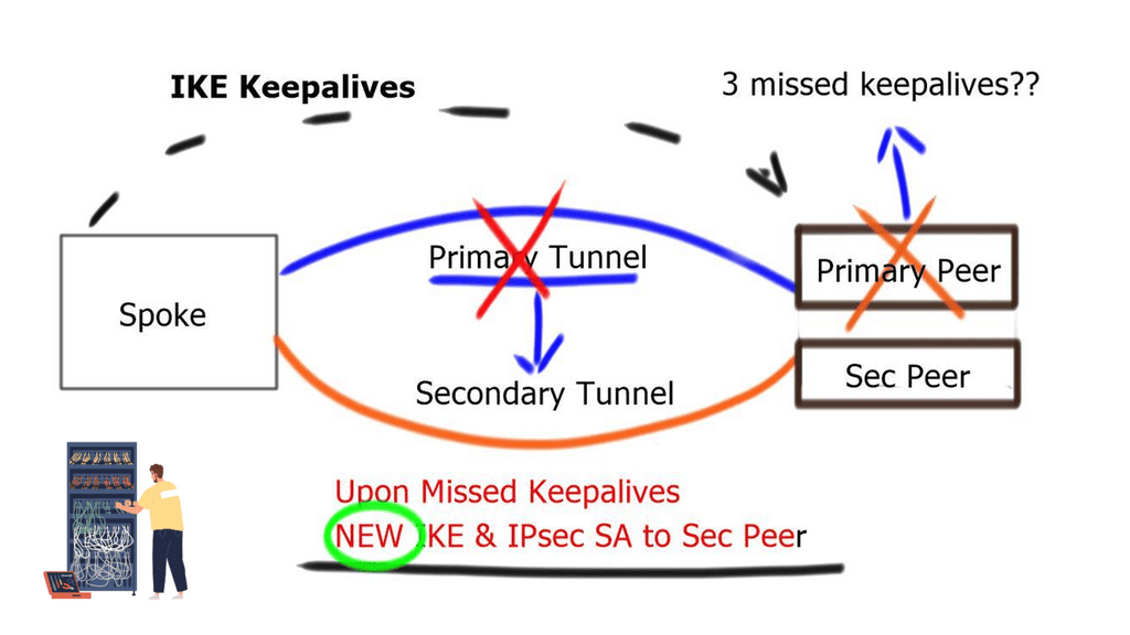
A lightweight mechanism known as IKE Keepalive can be deployed with the following command: crypto isakmp keepalive 60 30. The gateway device regularly sends messages to the remote gateway and waits for a response.

If three consecutive keepalive messages are unacknowledged, the Security Association ( SA ) to that peer is removed. IKE Keepalives help detect remote peer loss. However, it cannot detect whether remote networks behind the remote peer are reachable.
dead peer detection
Diagram: The need for dead peer detection.

GRE tunnel keepalive

GRE Tunnel keepalive works with point-to-point tunnels, not Dynamic Multipoint VPN ( DMVPN ). Missed keepalives bring down the GRE tunnel interface, not Phase 1 or 2 SAs. Recovery is achieved with dynamic routing or floating static routing over the tunnels. Convergence is at the GRE level and not the IPsec level.

The tunnel is down upon remote end failure, but IPsec SA and ISAKMP SA will remain active. Eventually, SAs are brought down when their lifetime expires. The default lifetime of the IKE Policy is 86,400 seconds ( one day ). GRE Tunnel Keepalives are used only with crypto-based configurations and not profile-based configurations.

A key point: IPv6 high availability and dynamic routing protocols

If you dislike using keepalives, you can reconverge based on the dynamic routing protocol. Routing protocols are deployed over GRE tunnels and configured routing metric influence-preferred paths.

Failover is based on a lack of receipt of peer neighbor updates, resulting in dead-time expiration and neighbor tear-down. Like GRE keepalives, it is not a detection mechanism based on IKE or IPsec. Phases 1 and 2 will remain active and expire only based on lifetime.

Dead peer detection ( DPD )

Dead peer detection is a traffic-based detection mechanism that uses IPsec traffic patterns to minimize the messages needed to confirm peer reachability. These checks are sent from each peer as an empty INFORMATIONAL exchange, which the corresponding receiving peer receives and retransmitted back to the initiating peer. The peer who initiated the liveness check can validate the returned packet by noting the message ID.

Unlike GRE or IKE keepalives, it does not send periodic keepalives. Instead, it functions because if IPsec traffic is sent and received, IPsec peers must be up and functioning. If not, no IPsec traffic will pass. On the other hand, if time passes without IPsec traffic, dead peer detection will start questioning peers’ liveliness.
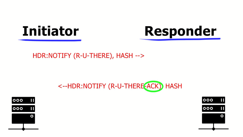
ipsec dpd
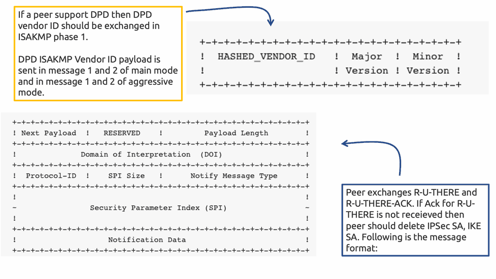
Diagram: IPsec DPD message format

IPsec DPD must be supported and enabled by both peers. Negotiated during Phase 1, therefore, help before the tunnel is negotiated. You must clear the tunnels SA if you enable DPD after the tunnel is up. DPD parameters are not negotiated; they are locally significant.

If a device sends a liveness check to its peer and fails to receive a response, it will go into an aggressive retransmit mode, transmitting five DPD messages at a configured interval. If these transmitted DPD exchanges are not acknowledged, the peer device will be marked dead, and the IKEv2 SA and the child IPsec Security Associations will be torn down.

IPsec DPD is built into IKEv2, NOT IKEv1.

The IPSec DPD initiator is disabled and enabled by default in responder mode on IOS routers. However, it must be allowed as an initiator on BOTH ends so each side can detect the availability of the remote gateway. Unlike GRE keepalives, DPD brings down Phase 1 and 2 security associations.
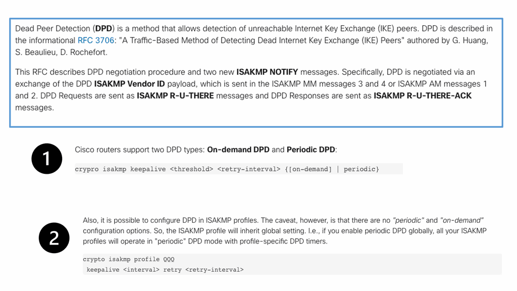
Dead Peer Detection
Diagram: Dead Peer Detection. Source Cisco.

Additional Details: Dead Peer Detection

Dead Peer Detection (DPD) is a network security protocol designed to detect a peer’s failure in an IPsec connection. It is a method of detecting when an IPsec-enabled peer is no longer available on the network. The idea behind the protocol is that, by periodically sending a packet to the peer, the peer can respond to the packet and prove that it is still active. The peer is presumed dead if no response is received within a specified time.

DPD is a critical feature of IPsec because it ensures a secure connection is maintained even when one of the peers fails. It is essential when both peers must always be available, such as for virtual private networks (VPNs). In such cases, DPD can detect when one of the peers has failed and automatically re-establish the connection with a new peer.

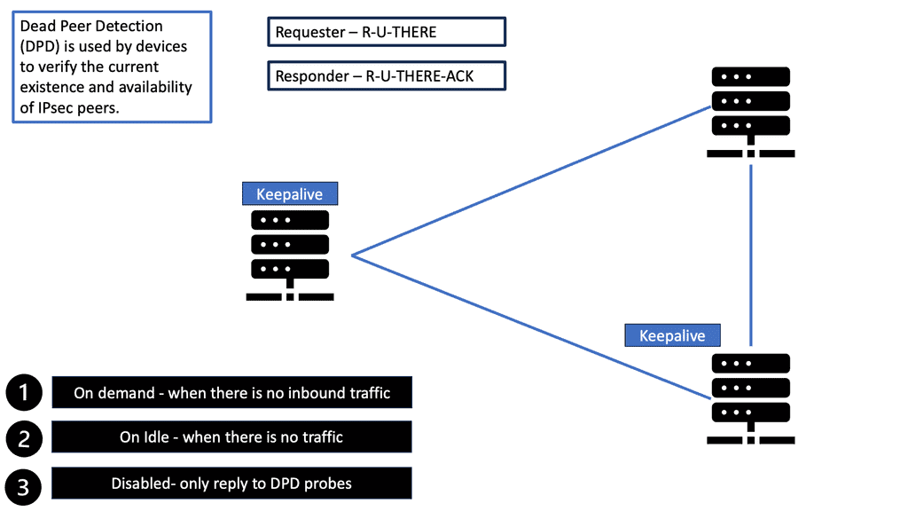
The DPD protocol sends a packet, known as an “R-U-THERE” packet, to the peer at periodic intervals. The peer then responds with an “R-U-THERE-ACK” packet. If the response is not received within a specific time, the peer is considered dead, and the connection is terminated.
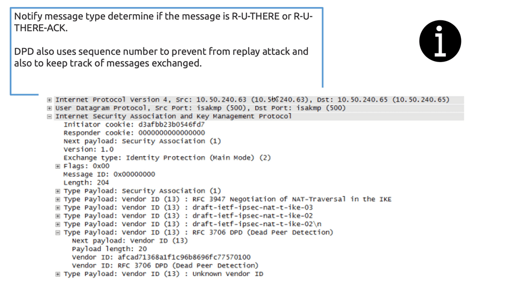
Dead Peer Detection
Diagram: Dead Peer Detection packet sniffer screenshot. Source WordPress Site.

**Dead Peer Detection**

When two routers establish an IPsec VPN tunnel between them, connectivity between the two routers can be lost for some reason. In most scenarios, IKE and IPsec do not natively detect a loss of peer connectivity, which results in network traffic being blackholed until the SA lifetime expires.

Dead Peer Detection (DPD) helps detect the loss of connectivity to a remote IPsec peer. When DPD is enabled in on-demand mode, the two routers check for connectivity only when traffic needs to be sent to the IPsec peer and the peer’s liveliness is questionable.

In such scenarios, the router sends a DPD R-U-THERE request to query the status of the remote peer. If the remote router does not respond to the R-U-THERE request, the requesting router starts to transmit additional R-U-THERE messages every retry interval for a maximum of five retries. After that, the peer is declared dead.

DPD is configured with the command crypto ikev2 dpd [interval-time] [retry-timeon-demand in the IKEv2 profile. 

DPD and Routing Protocols

Generally, the interval time is set to twice that of the routing protocol timer (2 × 20), and the retry interval is set to 5 seconds. In essence, the total time is (2 × 20(routing-protocol)) + (5 × 5(retry-count)) = 65 seconds. This exceeds the hold time of the routing protocol and engages only when the routing protocol is not operating correctly.

In a DMVPN network, DPD is configured on the spoke routers, not the hubs, because of the CPU processing required to maintain the state for all the branch routers.

Closing Points on Dead Peer Detection (DPD)

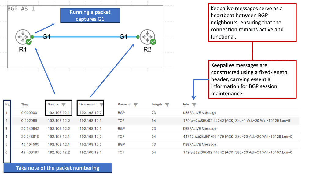
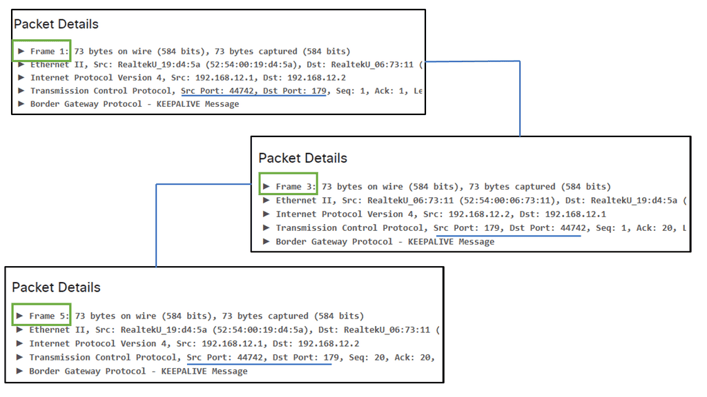
Dead Peer Detection operates by sending periodic “heartbeat” messages between peers to confirm their presence and operational status. If a peer fails to respond within a specified timeframe, it is flagged as “dead” or unreachable. This process allows the network to quickly identify and address connectivity issues, ensuring that data packets are not sent into a void, which could lead to security risks and inefficient bandwidth use. The efficiency of DPD lies in its ability to swiftly detect and react to changes in network connectivity, thereby minimizing downtime and potential disruptions.

In secure communication environments, such as Virtual Private Networks (VPNs), maintaining an always-on connection is critical. DPD plays a vital role in these settings by ensuring that all connected peers are actively participating in the network. This not only enhances security by preventing unauthorized access but also optimizes resource allocation by eliminating the likelihood of sending data to inactive peers. The proactive nature of DPD is essential for maintaining the integrity and performance of secure network connections.

To effectively implement Dead Peer Detection, network administrators should consider several best practices. These include configuring appropriate timeout intervals and retry counts to balance between prompt detection and avoiding false positives. Regular testing and monitoring of DPD settings can also help in fine-tuning the system to match the specific needs of the network. Additionally, integrating DPD with other monitoring tools can provide a comprehensive overview of network health, allowing for quick identification and resolution of connectivity issues.

Summary: Dead Peer Dedection

Dead Peer Detection (DPD) is a crucial aspect of network communication, yet it often remains a mystery to many. In this blog post, we delved into the depths of DPD, its significance, functionality, and the benefits it brings to network administrators and users alike.

Understanding Dead Peer Detection

At its core, Dead Peer Detection is a mechanism used in network protocols to detect the availability of a peer device or node. It continuously monitors the connection with the peer and identifies if it becomes unresponsive or “dead.” Promptly detecting dead peers allows for efficient network management and troubleshooting.

The Working Principle of Dead Peer Detection

Dead Peer Detection operates by periodically exchanging messages, known as “keepalives,” between the peers. These keepalives serve as a heartbeat signal, confirming that the peer is still active and responsive. A peer’s failure to respond within a specified time frame is considered unresponsive, indicating a potential issue or disconnection.

Benefits of Dead Peer Detection

Enhanced Network Reliability

By implementing Dead Peer Detection, network administrators can ensure the reliability and stability of their networks. It enables the identification of inactive or malfunctioning peers, allowing prompt actions to address potential issues.

Seamless Failover and Redundancy

DPD plays a vital role in seamless failover and redundancy scenarios. It enables devices to detect when a peer becomes unresponsive, triggering failover mechanisms that redirect traffic to alternate paths or devices. This helps maintain uninterrupted network connectivity and minimizes service disruptions.

Efficient Resource Utilization

With Dead Peer Detection in place, system resources can be utilized more efficiently. By detecting dead peers, unnecessary resources allocated to them can be released, optimizing network performance and reducing potential congestion.

Conclusion

In conclusion, Dead Peer Detection serves as a crucial element in network management, ensuring the reliability, stability, and efficient utilization of resources. Detecting and promptly addressing unresponsive peers enhances network performance and minimizes service disruptions. So, the next time you encounter DPD, remember its significance and its benefits to the interconnected world of networks.

MPLS

VPNOverview

VPNOverview

In today's digital age, where our lives are intertwined with the virtual world, ensuring our online privacy and security has become more crucial than ever. One powerful tool that has gained immense popularity is a Virtual Private Network, commonly known as a VPN. In this blog post, we will delve into the world of VPNs, understanding what they are, how they work, and why they are essential.

A VPN is a technology that establishes a secure and encrypted connection between your device and the internet. It acts as a tunnel, routing your internet traffic through an encrypted server, providing you with a new IP address and effectively hiding your online identity. This layer of encryption ensures that your online activities remain private and protected from prying eyes.

Enhanced Online Security: By encrypting your internet connection, a VPN shields your personal information from hackers, cybercriminals, and other malicious entities. It prevents unauthorized access to your sensitive data, such as passwords, credit card details, and browsing history, while using public Wi-Fi networks or even at home.

Anonymity and Privacy: One of the primary advantages of a VPN is the ability to maintain anonymity online. With a VPN, your real IP address is masked, making it difficult for websites and online services to track your online activities. This ensures your privacy and allows you to browse the internet without leaving a digital footprint.

Bypassing Geo-restrictions: Another remarkable feature of VPNs is the ability to bypass geo-restrictions. By connecting to a server in a different country, you can access content that is otherwise restricted or blocked in your region. Whether it's streaming platforms, social media, or accessing websites in censored countries, a VPN opens up a world of possibilities.

Server Network and Locations: When selecting a VPN, consider the size and diversity of its server network. The more server locations available, the better chances of finding a server close to your physical location. This ensures faster connection speeds and a smoother browsing experience.

Ensure that the VPN provider uses robust encryption protocols like OpenVPN, IKEv2, or WireGuard. These protocols offer high levels of security and can safeguard your data effectively. Additionally, check for features like a kill switch that automatically disconnects your internet if the VPN connection drops, preventing any potential data leaks.

User-Friendly Interface: A user-friendly and intuitive interface is essential for a smooth VPN experience. Look for VPN providers that offer easy-to-use apps for various devices and operating systems. A well-designed interface makes it effortless to connect to a VPN server and customize settings according to your preferences.

A VPN is an indispensable tool for anyone concerned about their online privacy and security. Not only does it encrypt your internet connection and protect your sensitive data, but it also offers the freedom to browse the internet without limitations. By choosing the right VPN provider and understanding its features, you can enjoy a safe and private online experience like never before.

Highlights: VPNOverview

### What is a VPN?

A Virtual Private Network, or VPN, is a service that creates a secure, encrypted connection between your device and a remote server operated by the VPN provider. This connection masks your IP address, making your internet activity virtually untraceable. Think of it as a private tunnel through which your data travels, hidden from anyone trying to peek in.

### Why Use a VPN?

Using a VPN offers several advantages, primarily focusing on privacy and security. When you connect to the internet through a VPN, your data is encrypted, protecting sensitive information like passwords and credit card numbers from hackers and snoopers. Additionally, by masking your IP address, a VPN helps maintain your anonymity, preventing websites and advertisers from tracking your online behavior.

### Accessing Geo-Restricted Content

One of the most popular reasons people turn to VPNs is to bypass geo-restrictions. Many streaming services, websites, and online platforms restrict content based on geographic location. By connecting to a server in a different country, a VPN allows you to access content as if you were physically present in that region. This feature has made VPNs a favorite tool for travelers and those looking to explore a broader range of online entertainment.

### Choosing the Right VPN

With numerous VPN providers available, selecting the right one can be overwhelming. Key factors to consider include the level of encryption, server locations, connection speed, and privacy policies. Some VPNs offer additional features like ad-blocking, malware protection, and no-log policies, which are crucial for ensuring your data remains confidential. It’s essential to research and choose a VPN that aligns with your needs and values.

Generic VPNs: Virtual Private Networks:

A: – ) A virtual private network (VPN) is a secure way to connect to a remote computer or network over the internet, allowing users to access otherwise unavailable resources. It is a private network that uses encryption technology to protect data traveling between two points, such as computers or a computer and a server. Companies commonly use VPNs to secure remote access to their internal networks and are also popular among individuals for protecting their privacy on the internet.

B: – ) A VPN creates an encrypted tunnel between the user’s computer and the remote network. All data that passes through this tunnel is secured and encrypted, making it much more difficult for hackers to intercept. This also allows users to access websites and services that their local government or ISP may block. VPNs can also spoof a user’s location, allowing them to access geo-restricted content.

C: – ) When setting up a VPN, users have several options. They can use a dedicated VPN service or configure their own VPN using open-source software. The type of VPN protocol used can also vary depending on the security requirements and desired performance.

The Concept of Tunneling:

VPNs provide a secure and private connection between your device and the internet by encrypting your data and routing it through a remote server. They offer several benefits, such as masking your IP address, protecting your data from hackers, and granting access to geo-restricted content.

Tunneling, on the other hand, is a technique used to encapsulate data packets within another protocol for secure transmission. It creates a “tunnel” by wrapping the original data with an additional layer of encryption, effectively hiding your online activities from prying eyes. Tunneling can be used independently or as part of VPN technology.

While both VPNs and tunneling provide security and privacy, their functionalities differ. VPNs act as a comprehensive solution by providing encryption, IP masking, and routing through remote servers. Tunneling, on the other hand, focuses primarily on data encapsulation and secure transmission.

**Understanding IPv6 Tunneling**

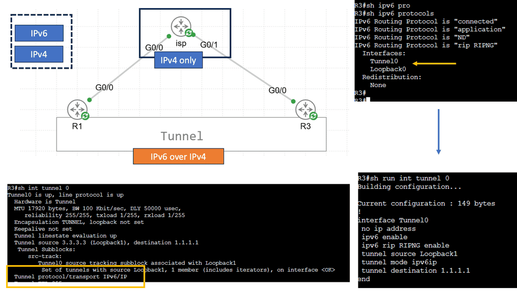
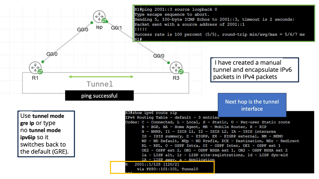
IPv6 tunneling is a mechanism that encapsulates IPv6 packets within IPv4 packets, allowing them to traverse an IPv4-only network infrastructure. The encapsulated IPv6 packets are then decapsulated at the tunnel endpoints, enabling communication between IPv6 networks over an IPv4 network.

There are several tunneling techniques commonly used in IPv6 deployments. Let’s explore a few of them:

– Manual Tunneling: Manual tunneling involves configuring the tunnel endpoints and the encapsulation mechanism. It requires explicit configuration on both ends of the tunnel and is often used for point-to-point connections or small-scale deployments.

– Automatic tunneling, also known as 6to4 tunneling, allows for automatic encapsulation and decapsulation of IPv6 packets within IPv4 packets. It utilizes the 2002::/16 prefix to create a virtual IPv6 network over the existing IPv4 infrastructure. While easy to set up, automatic tunneling may suffer from scalability issues and potential conflicts with private IPv4 addresses.

– Teredo Tunneling: Teredo tunneling is another automatic technique that enables IPv6 connectivity for hosts behind IPv4 NAT devices. It encapsulates IPv6 packets within UDP packets, allowing them to traverse NAT boundaries. Teredo benefits home and small office networks, as it doesn’t require manual configuration.

The Concepts of Encapsulation:

Encapsulation is a fundamental concept in networking that involves enclosing data packets within additional layers of information. This process enhances data security and facilitates its seamless transfer across networks. By encapsulating packets, valuable information is shielded from unauthorized access and potential threats.
There are several widely-used encapsulation protocols, each with its own unique features and applications. Let’s explore a few of them:

1. IPsec (Internet Protocol Security): IPsec provides a secure framework for encrypted communication over IP networks. It ensures data integrity, confidentiality, and authentication, making it ideal for secure remote access and virtual private networks (VPNs).
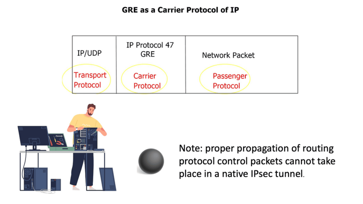
2. GRE (Generic Routing Encapsulation): GRE is a versatile encapsulation protocol commonly used to establish point-to-point connections between networks. It encapsulates various network layer protocols, enabling the transmission of non-IP traffic over IP networks.
3. MPLS (Multi-Protocol Label Switching): MPLS is a powerful encapsulation protocol that efficiently routes data packets through complex networks using labels. It enhances network performance, improves traffic engineering, and simplifies network management.

**Understanding GRE and Its Purpose**

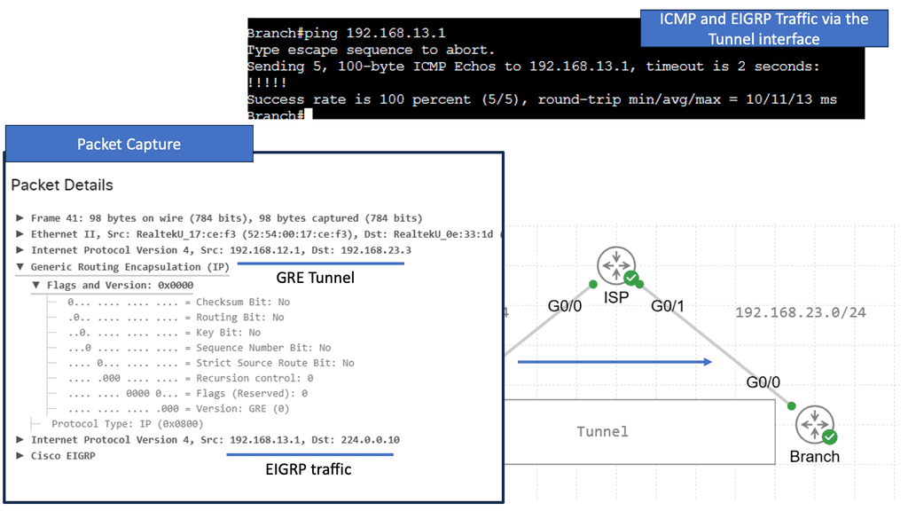
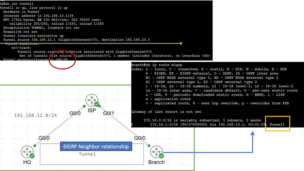
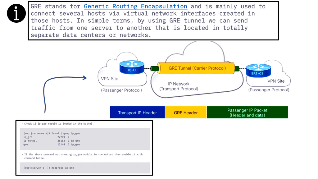
GRE is a tunneling protocol designed to encapsulate a wide variety of network layer protocols, enabling them to travel over an IP network as if they were part of a point-to-point connection. This encapsulation allows for the creation of virtual point-to-point links over an IP network, providing flexibility in routing and the ability to connect disparate networks seamlessly. GRE supports multicast packet encapsulation, making it an excellent choice for transporting protocols like OSPF and EIGRP across non-multicast networks.
**Configuring GRE on Cisco Devices**

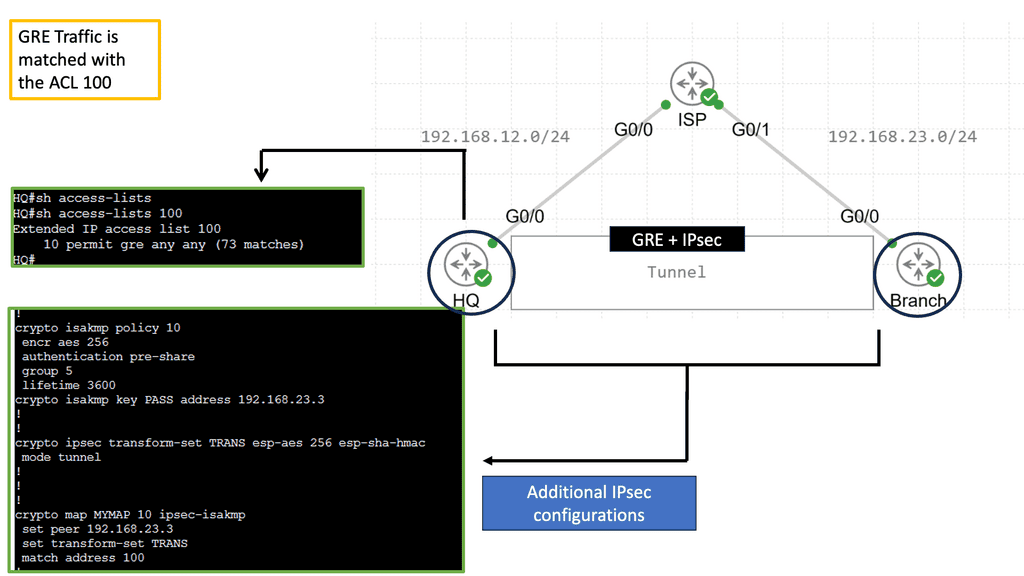
To configure GRE on Cisco devices, network administrators must establish a GRE tunnel interface and configure the source and destination IP addresses. This section will walk you through the step-by-step process of setting up a GRE tunnel on Cisco routers. We’ll dive into the necessary command-line interface (CLI) commands and explore configuration tips that can enhance your network’s performance. Understanding these configurations will empower you to implement GRE tunnels effectively, ensuring seamless communication between networks.
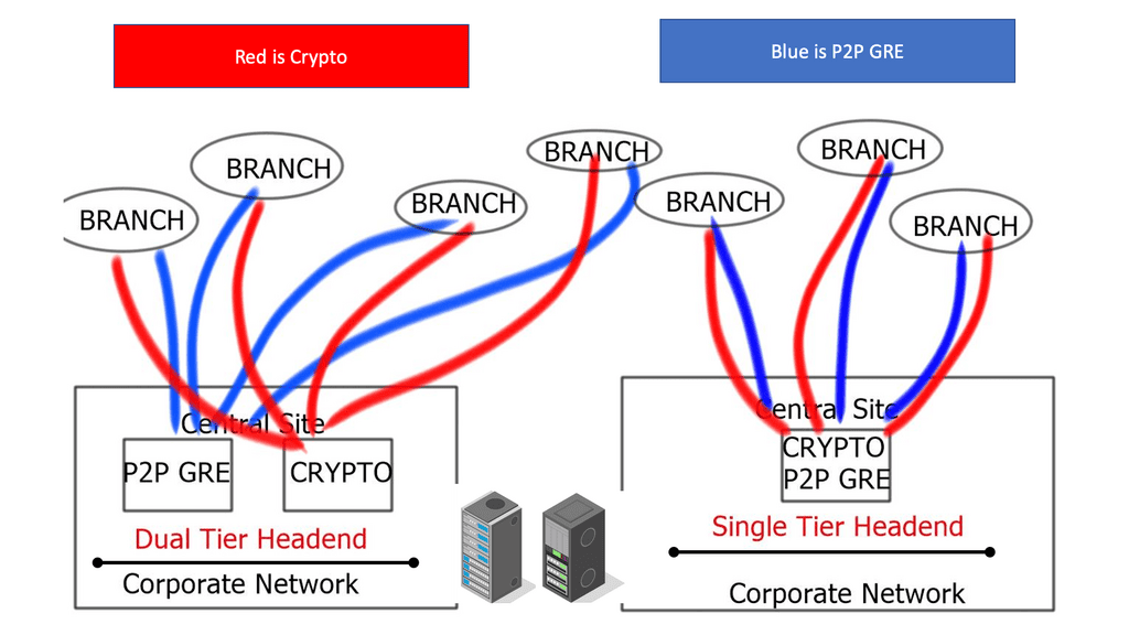
GRE without IPsec

VPN network

Layer 2 and Layer 3 technologies

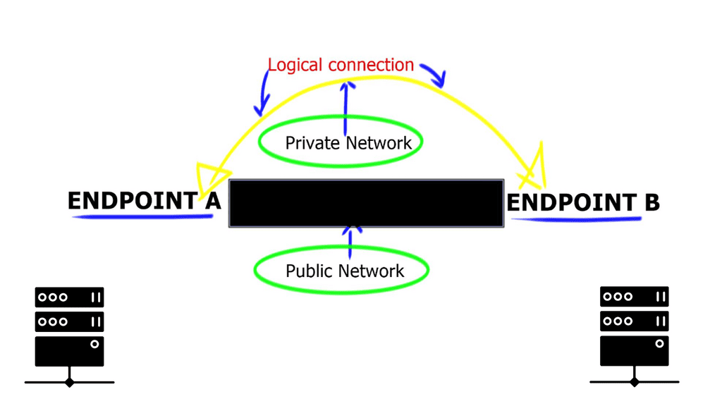
Virtual Private Networks ( VPNs ) are top-rated among businesses and individuals who access the Internet regularly and are provided by various suppliers. They are available as Layer 2 and Layer 3 technologies. They act as extensions, expanding private networks over public networks. Groups of different users share public networks; if privacy is required, encryption must be deployed to secure endpoint communication. The Internet is the most prevalent and widely known “public” network. In its simplest form, a VPNoverview, VPN connects two endpoints to form a logical connection.
VPN Technologies: Layer 2 and Layer 3 VPN

A VPN is a logical connection between two endpoints over a public network. Based on these logical connection models, VPN technologies can be classified as Layer 2 or Layer 3 VPNs based on their logical connections. The concept of establishing connectivity between sites over a Layer 2 or Layer 3 VPN is the same.

The concept involves adding a “delivery header” before the payload to get it to the destination site. The delivery header is placed at Layer 2 in Layer 2 VPNs and at Layer 3 in Layer 3 VPNs. GRE, L2TP, MPLS, and IPSec are examples of Layer 3 VPNs; ATM and Frame Relay are examples of Layer 2 VPNs.

VPNs provide a couple of features such as:

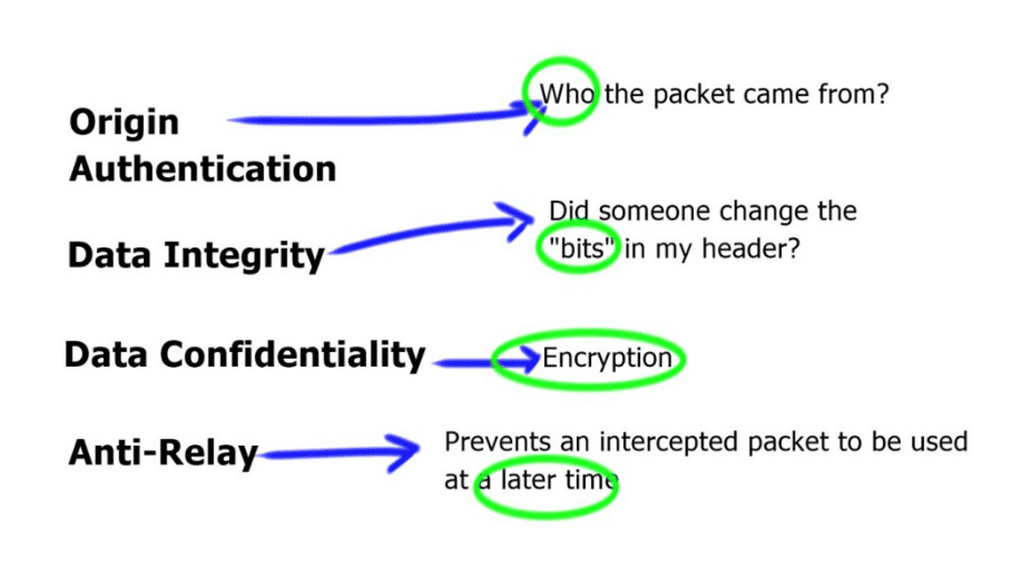
  • Confidentiality: preventing anyone from reading your data. This is implemented with encryption.
  • Authentication: verifying that the router/firewall or remote user sending VPN traffic is a legitimate device or router.
  • Integrity: verifying that the VPN packet wasn’t changed somehow during transit.
  • Anti-replay: preventing someone from capturing traffic and resending it, trying to appear as a legitimate device/user.

GRE with IPsec

VPN Types

There are two common VPN types that we use:

  • Site-to-site VPN

Organizations must deploy compatible VPN gateways or routers to implement a site-to-site VPN at each network location. These devices establish a secure tunnel between the networks, encrypting data packets and ensuring secure communication. Example: VPN protocols such as IPsec (Internet Protocol Security) or SSL/TLS (Secure Sockets Layer/Transport Layer Security) are commonly used to secure the connection. 

With the site-to-site VPN, we have a network device at each site. Between these two network devices, we build a VPN tunnel. Each end of the VPN tunnel encrypts the original IP packet, adds a VPN header and a new IP header, and then forwards the encrypted packet to the other end.

  • Client-to-site VPN

Client-to-site VPNs, or remote access VPNs, provide a secure connection between individual users or devices and a private network. Unlike site-to-site VPNs that connect entire networks, client-to-site VPNs are designed to grant remote access to authorized users. Establishing an encrypted tunnel ensures data confidentiality and integrity, protecting sensitive information from prying eyes.

The client-to-site VPN is also called the remote user VPN. The user installs a VPN client on his/her computer, laptop, smartphone, or tablet. The VPN tunnel is established between the user’s and remote network devices.

VPN Protocols

IPSec:

IPSEC, short for Internet Protocol Security, is a protocol for secure Internet communication. VPN, or Virtual Private Network, extends a private network across a public network, enabling users to send and receive data as if their devices were directly connected to the private network. IPSEC VPN combines the power of both these technologies to create a secure and private connection over the internet.

IPSec was created because the IP itself lacks security features. On layer three of the OSI model, IPSec provides confidentiality, integrity, authentication, and anti-replay features, but it isn’t a protocol.

Frameworks use a variety of protocols, and the advantage is that they can be changed in the future. If a new encryption algorithm is developed, such as DES, 3DES, or AES, IPSec may use it.

IPSec can be used for a variety of purposes:

  • Setting up a VPN tunnel from one site to another.
  • Tunneling a client-to-site VPN (remote user).
  • Traffic is authenticated and encrypted between two servers.

Example: IPSec VTI

### What is IPSec VTI?

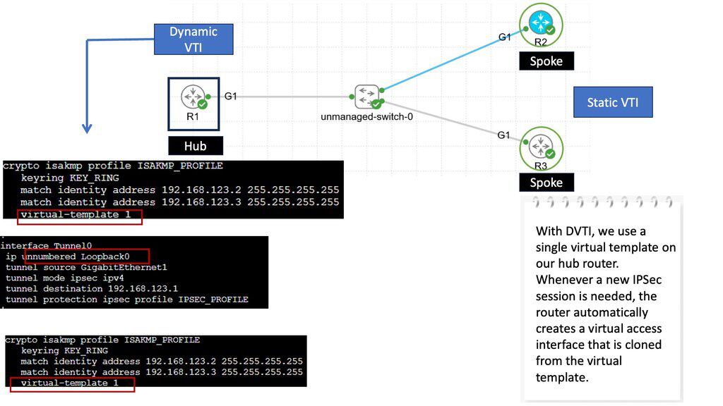
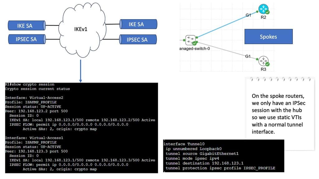
IPSec VTI, or Virtual Tunnel Interface, is a method that simplifies the configuration and management of IPSec tunnels. Unlike traditional IPSec configurations, which require multiple steps and complex policies, VTI offers a straightforward approach. By treating the tunnel as a virtual interface, network administrators can apply routing protocols directly to the tunnel, making the process seamless and efficient.

### How Does IPSec VTI Work?

IPSec VTI functions by encapsulating IP packets within an IPSec-protected tunnel. Here’s a simplified breakdown of the process:

1. **Establishing the Tunnel**: A virtual interface is created on each end of the tunnel, which acts as the endpoints for the secure communication.

2. **Encapsulation**: Data packets are encapsulated within IPSec headers, providing encryption and authentication.

3. **Routing**: The encapsulated packets are routed through the virtual tunnel interface, ensuring that they reach their destination securely.

4. **Decapsulation**: Upon arrival, the IPSec headers are stripped away, and the original data packets are delivered to the intended recipient.

IPSec Components

An IPSec implementation has several components. These include Security Associations (SAs), which define the parameters for secure communication, and Key Management protocols, such as Internet Key Exchange (IKE), which establish and maintain the cryptographic keys used for encryption and authentication. Additionally, IPSec employs encryption algorithms, such as AES or 3DES, and hash functions, like SHA-256, for data integrity.

IPSec Modes of Operation

IPSec supports two modes of operation: Transport mode and Tunnel mode. Transport mode encrypts only the payload of IP packets, leaving the IP header intact. It is typically used for end-to-end communication between hosts. On the other hand, Tunnel mode encapsulates the entire IP packet within a new IP packet, adding an extra layer of security. This mode is often employed for secure communication between networks.
Site to Site VPN

**PPTP VPN**

Developed by Microsoft, PPTP VPN is a widely used VPN protocol that creates a secure and encrypted tunnel between your device and the Internet. It operates at the data link layer of the OSI model and is supported by most operating systems, including Windows, macOS, Linux, Android, and iOS. Its simplicity and compatibility make it an attractive choice for many users.
An older VPN protocol, PPTP (Point to Point Tunneling Protocol), was released around 1995. A GRE tunnel is used for tunneling, and PPP is used for authentication (MS-Chap or MS-Chap v2). MPPE is used for encryption.
As PPTP has been around for a while, many clients and operating systems support it. PPTP, however, has been proven to be insecure, so you shouldn’t use it anymore.

Simplicity of Setup

Setting up PPTP is relatively straightforward, even for users with minimal technical expertise. Most operating systems offer built-in support for PPTP, eliminating the need for third-party software. Users can configure PPTP connections by entering server details provided by their VPN service provider, making it accessible to many users.

Security Considerations

While PPTP offers convenience and speed, it is essential to note that it may not provide the same level of security as other VPN protocols. PPTP uses MPPE (Microsoft Point-to-Point Encryption) to encrypt data packets, which has been criticized for potential vulnerabilities. Therefore, users with heightened security concerns may opt for alternative VPN protocols like OpenVPN or L2TP/IPSec.

**L2TP VPN**

L2TP VPN is a protocol for creating a secure connection between two endpoints over an existing network infrastructure. It operates at the data link layer of the OSI model and combines the best features of the L2F (Layer 2 Forwarding) and PPTP (Point-to-Point Tunneling Protocol) technologies. L2TP VPN ensures confidentiality and integrity during transmission by encapsulating and encrypting data packets.

In L2TP (Layer Two Tunneling Protocol), layer two traffic is tunneled over layer three connections, as the name suggests. Using L2TP, you can connect two remote LANs using a single subnet on both sites if you need to “bridge” them together. Because L2TP does not offer encryption, we often use it with IPSec. L2TP/IPSec is a combination of L2TP and IPSec

How L2TP Works

L2TP operates by establishing a tunnel between the sender and receiver. This tunnel encapsulates the data packets and ensures secure transmission. L2TP relies on other protocols, such as IPsec (Internet Protocol Security), to provide encryption and authentication, further enhancing the connection’s security.

**SSL VPN**

SSL VPN is a technology that allows users to establish a secure encrypted connection to a private network over the internet. Unlike traditional VPNs, which often require dedicated software or hardware, SSL VPN leverages the widely used web browser for connectivity. This makes it highly convenient and accessible for users across different devices and platforms.

HTTPS (Secure Sockets Layer) is a protocol for encrypting traffic between a web browser and a web server. HTTP allows you to browse the web in clear text. HTTPS is used for secure connections. The same technology can be used for VPNs as well.

Since SSL VPN uses HTTPS, you can use it pretty much anywhere. Most public WiFi hotspots allow HTTPS traffic, while others may block other traffic, such as IPSec. SSL VPN is also popular because you don’t have to use client software. Most SSL VPN solutions can access applications through a web browser portal. However, a software client might need some advanced features.

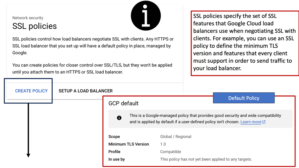
**Configuring SSL Policies on Google Cloud**

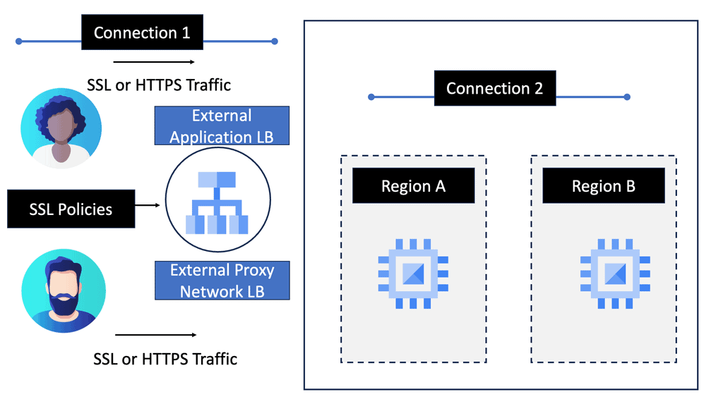
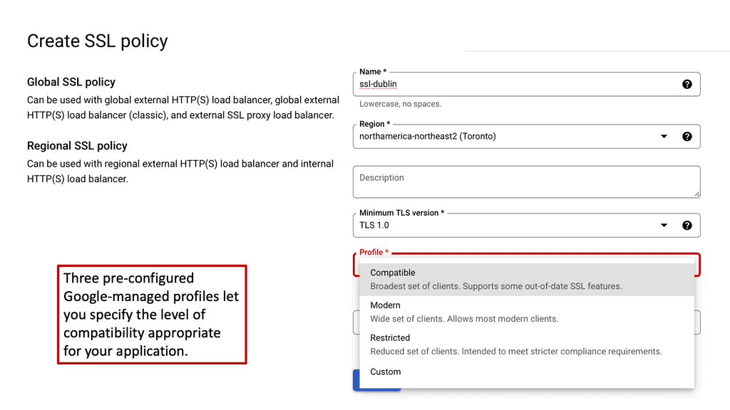
Google Cloud offers robust tools and services for managing SSL policies effectively. To configure SSL policies, you can utilize Google Cloud’s Load Balancing services. These services allow you to specify the minimum TLS version and select the appropriate cipher suites for your applications. By setting these parameters, you can ensure that your applications only support secure and up-to-date protocols, thus enhancing your overall security posture.

**Best Practices for SSL Policy Management**

Implementing SSL policies on Google Cloud requires a strategic approach. Here are some best practices to consider:

1. **Regularly Update Protocols and Ciphers**: Stay abreast of the latest security standards and update your SSL policies accordingly. This ensures that your applications are protected against emerging threats and vulnerabilities.

2. **Monitor and Audit SSL Configurations**: Regularly monitor your SSL configurations to identify any anomalies or misconfigurations. Conduct audits to ensure compliance with industry standards and internal security policies.

3. **Educate Your Team**: Ensure that your IT and security teams are well-versed in SSL policies and their importance. Conduct training sessions to keep them informed about the latest developments in cloud security.

SSL Policies

Use Case: Understanding Performance-Based Routing

– Performance-based routing is a dynamic routing technique that selects the best path for network traffic based on real-time performance metrics. Unlike traditional static routing, which relies on predetermined routes, performance-based routing analyzes factors such as network latency, packet loss, and bandwidth utilization to determine the most efficient path for data transmission.

– While performance-based routing offers numerous benefits, certain factors must be considered before implementation. First, organizations need to ensure that their network infrastructure is capable of collecting and analyzing real-time performance data. Monitoring tools and network probes may be required to gather the necessary metrics. Additionally, organizations must carefully plan their routing policies and prioritize traffic to align with their needs and objectives.

– Implementing performance-based routing requires a systematic approach. Organizations should start by conducting a comprehensive network assessment to identify potential bottlenecks and areas for improvement.

– Next, they should select suitable performance monitoring tools and establish baseline performance metrics. This information allows organizations to configure their routers and switches to enable performance-based routing. Regular monitoring and fine-tuning of routing policies are essential to maintain optimal network performance.

Google Data Centers – HA VPN

Understanding HA VPN

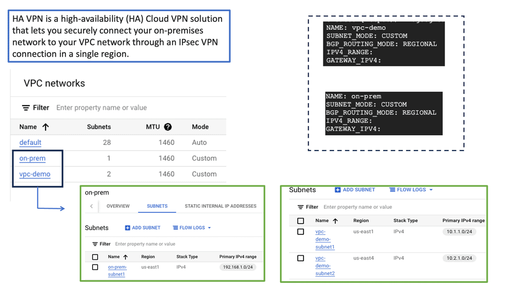
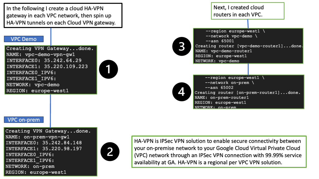
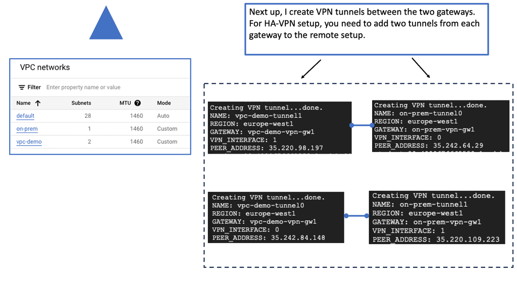
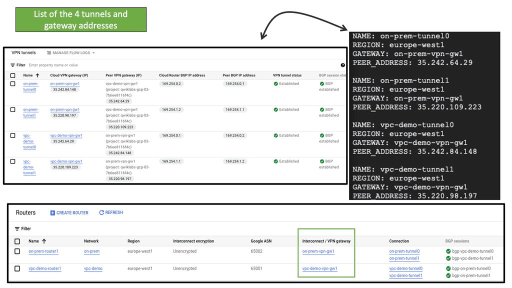
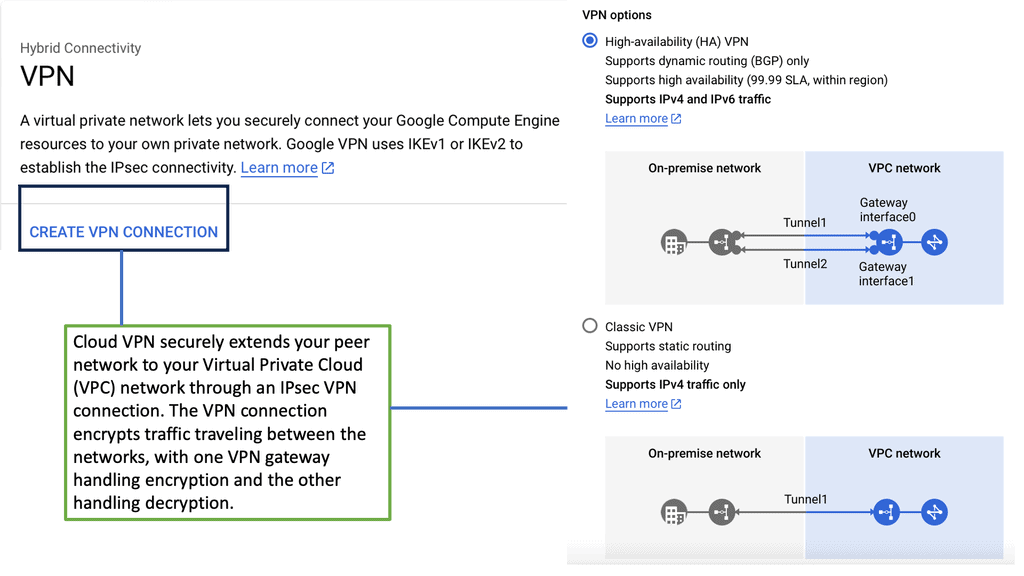
HA VPN, short for High Availability VPN, is a feature Google Cloud provides that allows for redundant and highly available VPN connections. It ensures that even if one VPN tunnel fails, traffic seamlessly switches to the backup tunnel, minimizing downtime and ensuring continuous connectivity. This resilience is crucial for businesses that rely heavily on uninterrupted network access.

The HA VPN Configuration offers several advantages over traditional VPN setups. Firstly, it provides automatic failover, reducing the risk of service disruptions. Secondly, it offers improved network reliability, as the redundant tunnels ensure continuous connectivity. Additionally, HA VPN Configuration simplifies network management by eliminating the need for manual intervention during failover events.

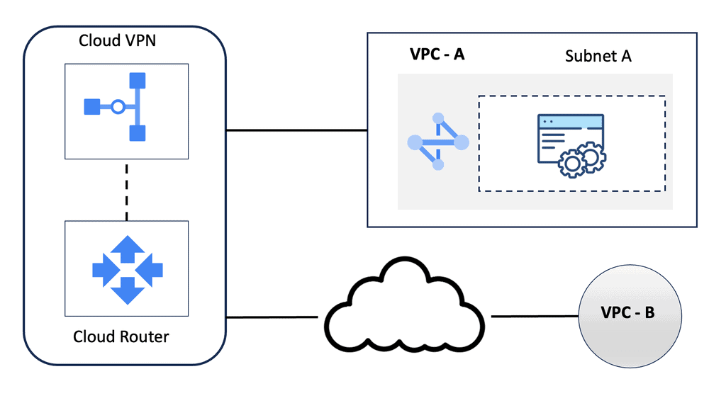
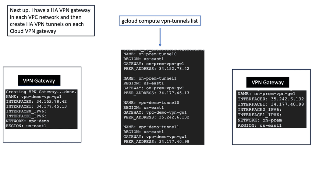
Configuring HA VPN in Google Cloud is straightforward. First, you need to create a virtual private network (VPC) in Google Cloud. Next, you’ll set up the HA VPN gateway and configure the VPN tunnels. Make sure to select the appropriate routing options and encryption settings. Lastly, you’ll establish the VPN connection between your on-premises network and the HA VPN gateway in Google Cloud.

WAN Edge Services

What is Network Address Translation?

Network Address Translation, commonly known as NAT, is a fundamental concept in computer networking. It is a technique used to modify network address information in IP packet headers while traversing through a router or firewall. The primary objective of NAT is to enable multiple devices on a private network to share a single public IP address, thus conserving IP address space.

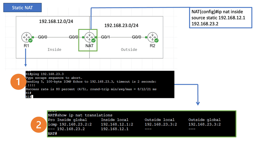
Static NAT: Static NAT, also known as one-to-one NAT, involves mapping a public IP address to a specific private IP address. This type of NAT is commonly used when a particular device within a private network needs to be accessible from the public internet.

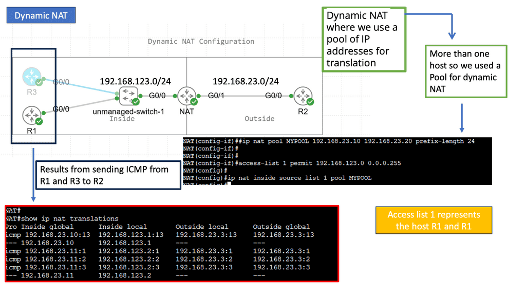
Dynamic NAT: Dynamic NAT operates similarly to Static NAT but with a significant difference. Instead of using one-to-one mapping, Dynamic NAT allows a pool of public IP addresses to be shared among multiple private IP addresses, allowing for a more efficient use of the available IP addresses.

Port Address Translation (PAT): PAT, also called NAT Overload, is a variation of Dynamic NAT. In PAT, multiple private IP addresses are mapped to a single public IP address using different port numbers. This technique enables many devices on a private network to access the internet simultaneously, utilizing a single public IP address.

– IP Address Conservation: NAT helps conserve the limited pool of public IP addresses by allowing multiple devices to share a single IP.

Enhanced Security: By hiding the internal IP addresses, NAT provides an additional layer of security, making it harder for external entities to access devices directly within the private network.

– End-to-End Connectivity: NAT can introduce challenges in establishing direct communication between devices on different private networks, limiting specific applications and protocols.

– Impact on IP-based Services: Some IP-based services, such as VoIP or peer-to-peer applications, may not function optimally when NAT is involved.

Advanced VPNs

Understanding DMVPN:

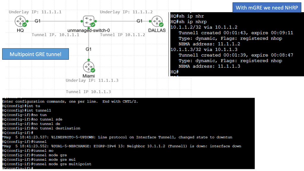
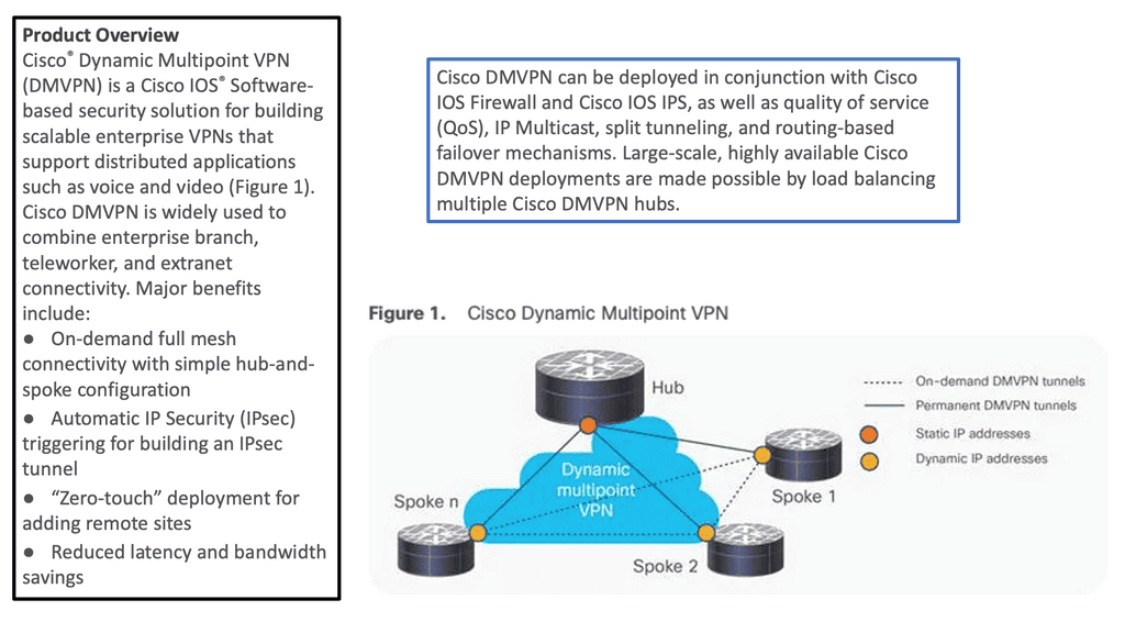
DMVPN is a dynamic VPN technology that enables the creation of secure overlay networks over existing infrastructure. Utilizing multipoint GRE tunnels allows for the seamless establishment of encrypted connections between multiple sites, regardless of geographical location. This flexibility makes DMVPN an appealing choice for organizations with distributed networks.
A -: Multipoint GRE Tunnels: Multipoint GRE (mGRE) tunnels serve as the foundation of DMVPN. These tunnels establish a virtual network that connects multiple sites, enabling direct communication between them. Using a single tunnel interface for all connections, mGRE simplifies the network architecture and reduces complexity.

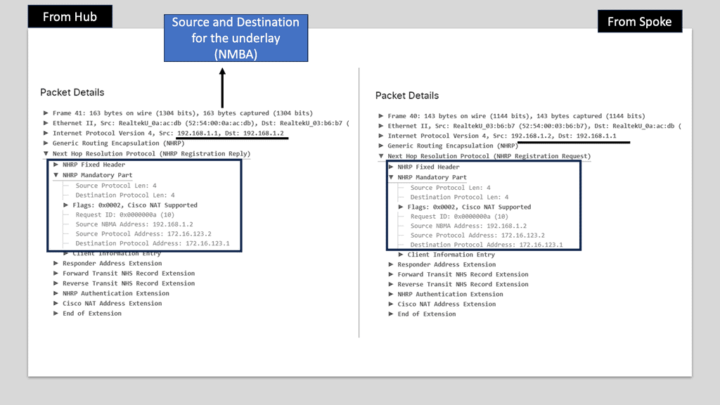
B -: Next-Hop Resolution Protocol (NHRP): NHRP plays a crucial role in DMVPN by providing dynamic mapping of tunnel IP addresses to physical addresses. It allows spoke routers to dynamically register their IP addresses with a hub router, eliminating the need for static mappings. NHRP also handles traffic forwarding among the spoke routers, ensuring efficient routing within the DMVPN network.

C: – IPsec Encryption: IPsec encryption ensures the security of data transmitted over the DMVPN network. IPsec provides a secure tunnel between the participating routers, encrypting the traffic and preventing unauthorized access. This encryption ensures the data’s confidentiality, integrity, and authenticity over the DMVPN network.

Understanding MPLS VPN

MPLS VPN, short for Multiprotocol Label Switching Virtual Private Network, is a networking technique that combines the advantages of both MPLS and VPN technologies. At its core, MPLS VPN allows for creating private and secure networks over a shared infrastructure. Unlike traditional VPNs, which rely on encryption and tunneling protocols, MPLS VPN utilizes labels to route traffic efficiently.

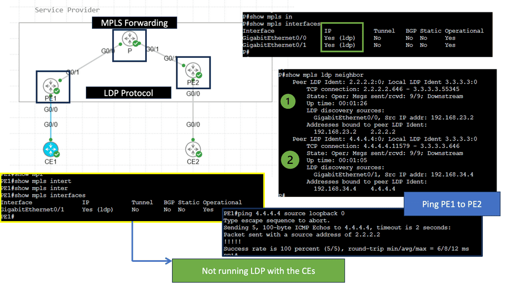
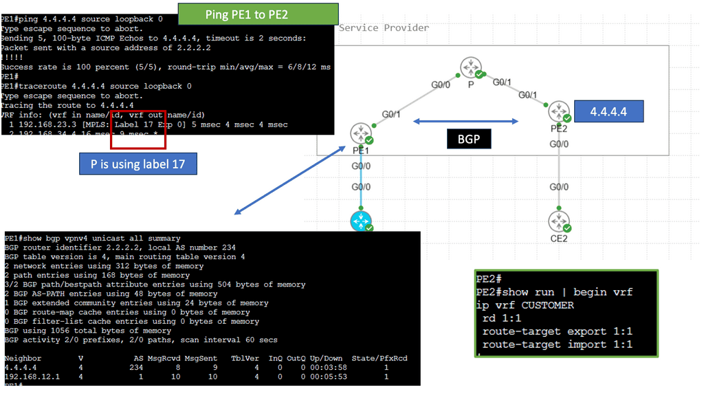
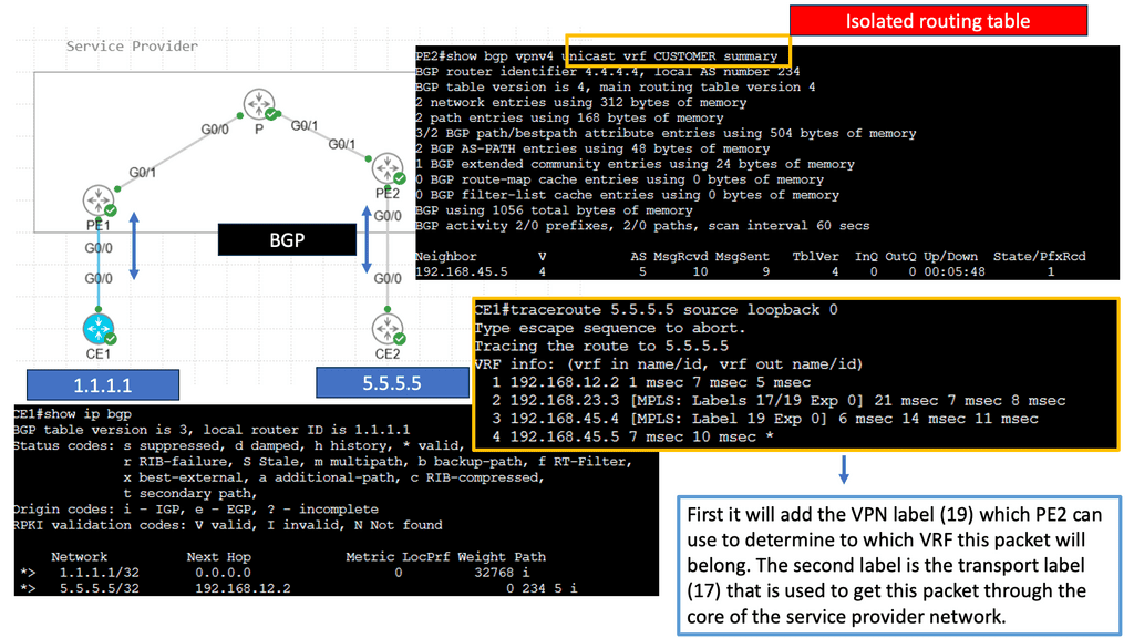
Understanding the magic of MPLS VPN’s underlying operation is essential to comprehending its magic. In this section, we’ll explore the key components: Provider Edge (PE) routers, Provider (P) routers, and Customer Edge (CE) routers. We’ll uncover the label-switching mechanism, where labels are assigned to packets at the ingress PE router, facilitating fast and efficient forwarding across the MPLS network.

Understanding GETVPN

GETVPN, short for Group Encrypted Transport VPN, is a network technology that provides secure communication across wide area networks. Unlike traditional VPN solutions, GETVPN focuses on providing encryption at the network layer, ensuring data transmission confidentiality, integrity, and authenticity.
GETVPN offers a range of powerful features, making it an attractive choice for organizations seeking robust network security. One such feature is its ability to provide scalable encryption for large-scale networks, allowing seamless expansion without compromising performance. Additionally, GETVPN supports multicast traffic, enabling efficient communication across multiple sites.

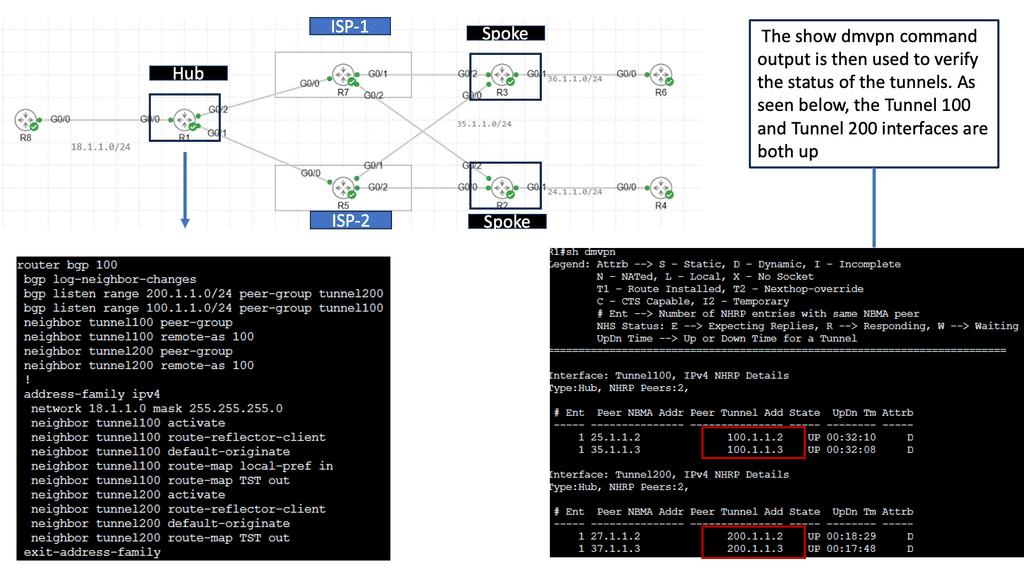
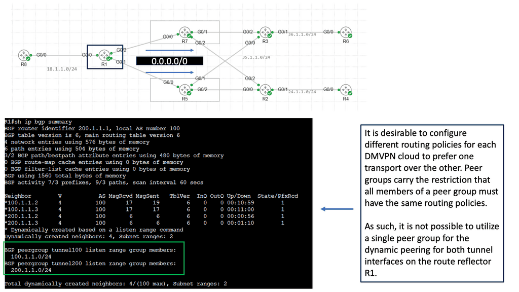
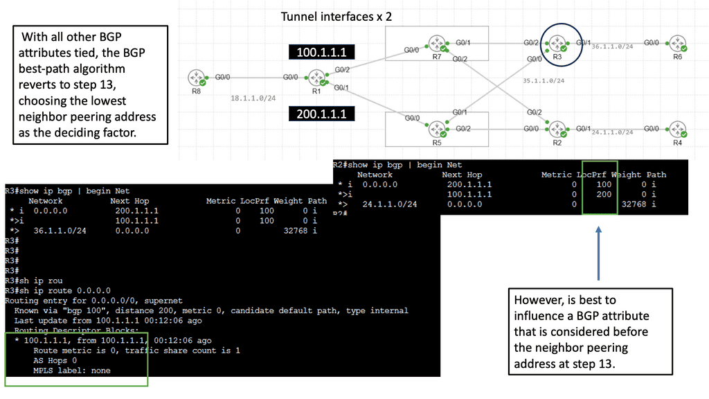
Use Case: DMVPN Dual Cloud, Single Hub

Exploring Single Hub Dual Cloud Architecture

The single hub dual cloud deployment model is an advanced DMVPN configuration that offers enhanced redundancy and scalability. In this architecture, a single hub site is the central point for all remote sites, while two separate cloud service providers (CSPs) are used for internet connectivity. This setup ensures that even if one CSP experiences an outage, connectivity remains intact through the other CSP.

– Improved Redundancy: By leveraging two separate CSPs, the single hub dual cloud DMVPN architecture minimizes the risk of connectivity loss due to a single point of failure.

– Enhanced Scalability: With this deployment model, businesses can quickly scale their network infrastructure by adding new remote sites without disrupting existing connections.

– Optimized Performance: Using multiple CSPs allows for load balancing and traffic optimization, ensuring efficient utilization of available bandwidth.

**Layer 2 and Layer 3 VPN comparison**

Therefore, Layer 2 and Layer 3 VPNs differ in the following ways:

As far as Layer 2 is concerned, there is no routing interaction between the customer and the service provider. Routes can be exchanged between CE and PE routers in L3VPN.

Customers can run any Layer 3 protocol between sites using Layer 2. The SP network does not recognize Layer 3 protocol since it transports Layer 2 frames. Even though IP is prevalent in many enterprise networks, non-IP protocols like IPX or SNA are also commonly used. This would preclude using a Layer 3 VPN for transporting such traffic.

In the Layer 2 case, multiple (logical) interfaces are required between each CE and the corresponding PE, one per remote CE. When the CE routers are fully meshed, and there are 10 CE routers, each CE has nine interfaces (DLCIs, VCs, and VLANs, depending on the media type) to the PE. Since the PE will route traffic to the appropriate egress CE in the Layer 3 VPN, one connection between each CE and the PE is sufficient.

Before you proceed, you may find the following posts helpful:

  1. IPsec Fault Tolerance
  2. SSL Security
  3. Dead Peer Detection
  4. SDP VPN
  5. Generic Routing Encapsulation

VPNOverview

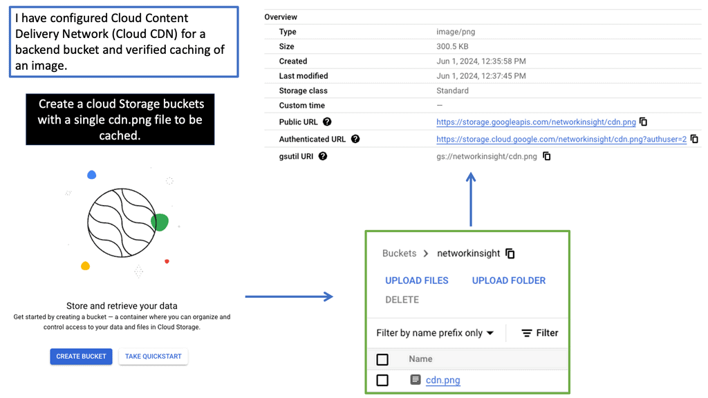
Google Cloud CDN

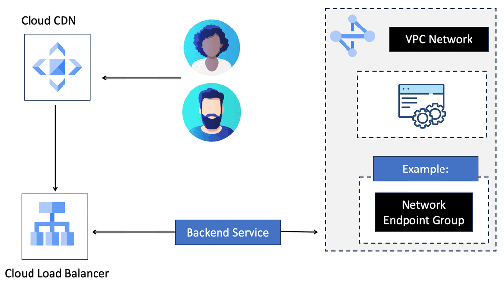
Understanding Cloud CDN

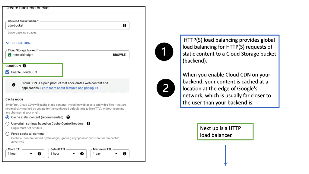
Cloud CDN is a globally distributed network of edge points of presence (PoPs) that caches your website’s static and dynamic content. By storing copies of your content closer to your users, Cloud CDN significantly reduces latency and improves response times. It leverages Google’s robust infrastructure to deliver content efficiently, making it an ideal choice for websites with a global audience.

Cloud CDN offers a range of features designed to optimize content delivery. Firstly, it automatically caches static content, such as images, CSS files, and JavaScript, reducing the load on your origin servers. This caching mechanism ensures that subsequent requests for the same content are served from the edge locations, minimizing the need to fetch data from the origin.

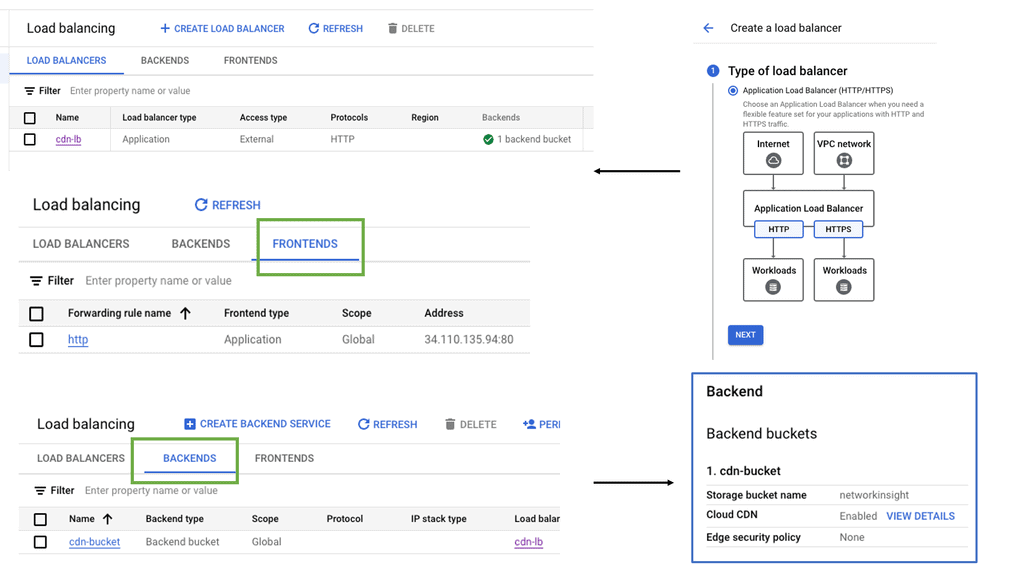
Additionally, Cloud CDN supports dynamic content caching, enabling it to cache personalized or frequently accessed content on the edge, improving response times. It also integrates seamlessly with other Google Cloud services, such as Load Balancing and Cloud Storage, providing a comprehensive solution for your website’s performance needs.

DMVPN. A layer 3 VPN over the WAN.

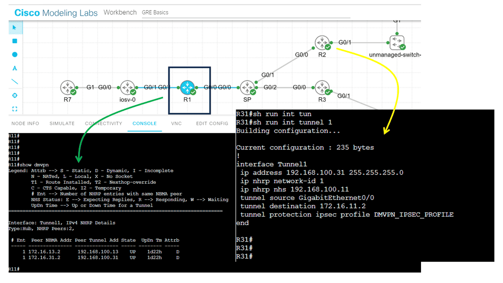
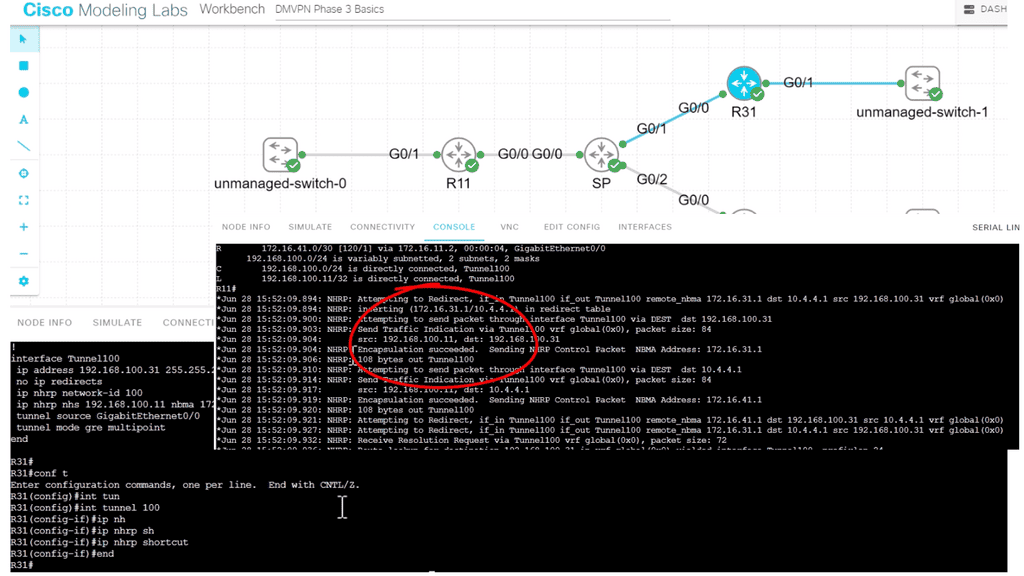
DMVPN can be used as an overlay with IPsec or GRE. It enables a VPN from the DMVPN hub and the spokes, creating a DMVPN network. Depending on the DMVPN phase, we will have different VPN characteristics and routing techniques. We started with DMVPN Phase 1, the traditional hub, and spoke to what is more widely used today, DMVPN Phase 3, which offers on-demand spoke-to-spoke tunnels.

The screenshot from the lab guide below shows that we have R11 as the hub and R31 as the spoke. We are operating with DMVPN phase 3. We know this as we have a “Traffic Indication” message sent from R11 to the spokes. A “Traffic Indication” is core to DMVPN Phase 3 and is used when there has been spoken-to-spoke traffic.

The hub tells the spoke that there is a more optimal path and to go directly to the other spoke instead of going via the hub. Another key VPN configuration value for DMVPN Phase 3 is the command: Tunnel mode gre multipoint on the spokes. Both spokes and hubs use multipoint GRE instead of point-to-point GRE.

DMVPN Phase 3
Diagram: DMVPN Phase 3 configuration

Back to basics with VPNOverview

Concepts of VPN

A VPN allows users to expand a private network across an untrusted network. The term “Virtual” emphasizes that a logical private connection virtually extends the private network. A VPN can be secure or insecure. We can use IPsec to secure VPNs. In addition, when IPsec VPNs are used, traffic will be protected to ensure that an observer cannot view the plaintext data.

Almost every operating system ships with an IPsec VPN client, and numerous hardware devices provide various IPsec VPN gateway functionality. As a result, IPsec VPNs are a popular choice now for secure connectivity over the Internet or for delivering secure communications over untrusted networks.
VPNOverview

Concepts of IPSec

– IPsec (Internet Protocol Security) is a network security protocol that encrypts IP packets. It protects data communications between two or more computers by providing authentication and encryption. It is one of the world’s most widely used security protocols, as it is the de facto standard for protecting data in transit across the Internet. It also secures private networks, such as those used by corporations and government agencies.

– IPsec works by authenticating and encrypting each IP packet of a communication session. It uses two main protocols to provide this security: Authenticated Header (AH) and Encapsulated Security Payload (ESP). AH provides authentication and data integrity, while ESP includes encryption. The two protocols can be used together or separately to provide the desired level of security.

– IPsec can secure various communication protocols, including TCP, UDP, and ICMP. It is also used to protect mobile devices, such as smartphones, which require secure communication between them and the network they are attached to. IPsec also provides an additional layer of security by providing access control. This means that only authenticated users can access the data. This is especially important when protecting sensitive information and corporate data.

IPsec VPN
Diagram: IPsec VPN. Source Wikimedia.

Concepts of IKEv1 vs IKEV2

IKEv1 and IKEv2 are two major versions of the Internet Key Exchange (IKE) protocol; both are used to create secure Virtual Private Networks (VPNs). IKEv1 was the original version, developed in 1998, and IKEv2 was released in 2005.

Both versions of IKE use the same cryptographic algorithms and protocols, but IKEv2 is the more secure version due to its additional features. For example, IKEv2 is capable of automatic re-keying, which IKEv1 does not support, and the IKEv2 protocol is implemented more structured and modularly than IKEv1. Additionally, IKEv2 has more advanced authentication methods, such as EAP and XAUTH, and supports the authentication of multiple peers.

IKEv2 is also more efficient than IKEv1, as it is designed to reduce the amount of data sent over the network. This helps to increase the speed of the VPN connection. Finally, IKEv2 is more resilient in the face of network issues and disruptions, as it supports the ability to reconnect automatically.

It is important to note that IKEv1 and IKEv2 have advantages and drawbacks. For example, IKEv1 is more straightforward to deploy and configure but is less secure than IKEv2. On the other hand, IKEv2 is more secure but may require more effort to set up.

When deciding between IKEv1 and IKEv2, the network’s security requirements and the VPN connection’s desired performance must be considered.

Layer 3 and Layer 2 VPNs

Firstly, for a VPNoverview, let’s start with the basics of Layer 2 and 3 VPNs. Layer 2 virtual private network: Frame Relay or ATM Permanent Virtual Circuits ( PVC ) utilize someone else’s public transport to build private tunnels with ( VC ) virtual circuits. A Virtual Private LAN Service ( VPLS ) network creates tunnels over the Multi-Protocol Label Switched ( MPLS ) core. Ethernet VLAN or QinQ is also an example of a Layer 2 VPN.

Layer 3 virtual private network: Generic Routing Encapsulation ( GRE ) tunnels and MPLS tunnels between Service providers and customers are examples of a Layer 3 VPN. Also, IP Protocol Security ( IPsec ) tunnels, which are the focus of this post, are an example of a Layer 3 VPN. The critical advantage of Layer 3 IPsec VPNs is the independence of the access method. You can establish a VPN if you establish IPv4 or IPv6 connectivity between two endpoints. VPNs do not require encryption, but encryption can take place if needed.

What is IP protocol security ( IPsec )?

IPsec is a protocol suite that provides security services for IP packets at the network layer. IPsec creates P2P associations between tunnel endpoints. Authenticates and encrypts packets. A broad term that encompasses the following features;

vpn overview
Diagram: VPN overview

VPNoverview and encryption

In the next stage of this VPNoverivew, we will discuss encryption. VPNs encrypt packets with symmetric ciphers, e.g., DES, 3DES, and AES. Ciphers work with the concept of key exchange. In particular, the symmetric cipher key used to encrypt on one side is the same key to decrypt on another side. The same key is used at both endpoints.

Symmetric encryption contrasts with asymmetric encryption ( public key algorithms ), which utilizes separate public and private keys – one for encryption and another for decryption. The encryption key is known as the public key and is made public. The private key is kept secret and used for decryption.

Encryption takes plain text and makes it incomprehensible to unauthorized recipients. A matching key is required to decode the “incomprehensible” text into readable form. Decryption is the reverse of encryption. It changes the encrypted data back to plain text form. Encryption takes effect AFTER Network Address Translation ( NAT ) and Routing.

IPsec and ISAKMP

ASA uses ISAKMP negotiations and IPsec security features to establish and maintain tunnels for LAN-to-LAN and client-to-LAN VPNs. Tunnels are dynamically negotiated with control plane protocols, IKEv1/IKEv2, over UDP port 500. ISAKMP is a protocol that allows two VPN endpoints to agree and build IPsec security associations. ASA supports both ISAKMP version 1 and ISAKMP version 2. IKEv1 supports connections from legacy Cisco VPN clients, and IKEv2 supports the AnyConnect VPN client.

There are two main phases for tunnel establishment. The first phase objective is to establish and create a tunnel. The second Phase governs traffic within the tunnel. ISAKMP security associations govern tunnel establishment, and IPsec security associations govern traffic within the tunnel.

Key elements agreed upon in Phase 1 before endpoints proceed to Phase 2

Phase 1Establishes-preliminary tunnel; used to protect later ISAKMP negotiation messages.
Securely negotiate the encryption parameters for Phase 2.
Phase 1 results in ISAKMP SA
Phase 2Creates the secure tunnel used to protect end-point data.
IPSEC SA is used to transport protected traffic.
Tunnel mode, AH** & ESP are negotiated.
Phase 1 results in IPSEC SA

**AH only supports authentication and is therefore rarely used for VPN. AH can be used in IPv6 OSPFv3 for neighbor authentication.

KEY POINT: Phase 1 is bidirectional, and Phase 2 uses two unidirectional messages. Phase 2 ESP and AH cannot be inspected by default ASA policies, which may become problematic for stateful firewalls. Phase 1 uses IKE UDP and UDP, which are inspected by default.

IKEv1 vs IKEv2

The main difference between IKEv1 and IKEv2 is authentication methods. With IKEv1, both endpoints must use the same authentication method; the encryption method must be symmetric.

IKEv2 is more flexible and does not need symmetric authentication types—it is possible to have certificates at one end and pre-shared keys at the other end.

IKE initiator sends all of the policies through a proposal. It’s up to the remote end to respond, check its policies, and agree if the receiving policies are acceptable. Policies are matched sequentially. The first match was utilized with an implicit deny at the bottom. IKEv2 allows multiple encryptions and asymmetric authentication types for a single policy.

**Two IKE modes: Main and aggressive mode*8

IKE has two modes of operation: Main Mode and Aggressive Mode.

Main Mode uses more ( 6 ) messages than Aggressive Mode and takes longer to process. It’s slower but protects the identity of communicating with peers.

Aggressive, useless ( 3 ) messages are quicker but less secure. Aggressive mode lets people know the endpoint identity, such as an IP address or Fully Qualified Domain Name ( FQDN ). It does not wait for the secure tunnel before you exchange your identity, allowing flexible authentication.

NAT-T and IPsec

IPsec uses ESP to encrypt data. It does this by encapsulating the entire inner TCP/UDP datagram within the ESP header. Like TCP and UDP, ESP is an IP protocol, but unlike TCP and UDP, it does not have any port information. No ports prevent ESP from passing through NAT / PAT devices. Nat-T auto-detects transit NAT / PAT devices and encapsulates IPsec traffic in UDP datagrams using port 4500. By encapsulating ESP into UDP, it now has port numbers, enabling the pass-through of PAT/NAT gateways.

ISAKMP does not have the same problem, as its control plane already works on UDP. As with any data encryption, it is always important to compare what is on the market to keep your data safe.

Guide: GetVPN Overview

GETVPN, or Group Encrypted Transport Virtual Private Network, is designed to provide secure communication over a public network infrastructure. It allows for creating a virtual private network (VPN) that enables secure communication between different locations or branches of an organization. Unlike traditional VPNs, GETVPN operates at the network layer, ensuring confidentiality, integrity, and authenticity.

Implementing GETVPN requires careful planning and configuration. The deployment process involves critical components such as Key Servers (KS), Group Members (GM), and Group Domain of Interpretation (GDOI). By carefully configuring these elements, organizations can establish a secure network architecture that aligns with their specific requirements. Proper key management and pre-shared keys are also critical aspects of GETVPN deployment.

We have 1 Key Server and 2 Group Members in the diagram below. A description of their roles and protocol used as follows:

Key Servers:

At the heart of GETVPN are the key servers responsible for generating and distributing encryption keys. All the devices within the group use these keys to encrypt and decrypt network traffic. Key Servers ensure that all network devices have synchronized encryption keys, maintaining a secure communication channel.

Group Members:

Group Members refer to the network devices that participate in the GETVPN network. These can be routers, switches, or even firewalls. Group Members establish secure tunnels with each other and exchange encrypted traffic. They utilize the encryption keys provided by the Key Servers to protect the confidentiality and integrity of the data.

Group Domain of Interpretation (GDOI):

GDOI is a protocol GETVPN uses to manage the encryption keys and maintain synchronization among the Key Servers and Group Members. It handles key distribution, rekeying, and critical management operations, ensuring that all devices within the group have up-to-date encryption keys.

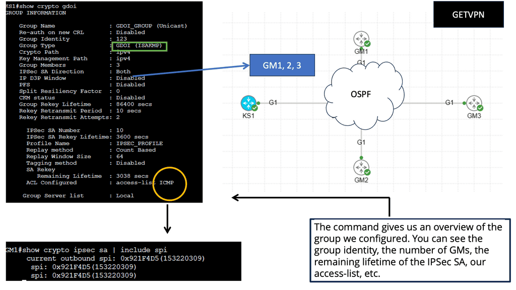
OSPF is the routing protocol used on the WAN. The unmanaged switch in the middle represents a private WAN. OSPF is configured on the GM routers to advertise the loopback interfaces.

Below, we can verify that the GM has registered with the KS; we can see the access list used for encryption and the KEK/TEK policies, including the IPSec SA that the GM will use. Let’s take a closer look at IPSec SA. This will be the same for all GMs. 

Summary: VPNOverview

In the digital age, where our lives are increasingly intertwined with the internet, safeguarding our online privacy has become more crucial than ever. One powerful tool that has gained significant popularity in recent years is the Virtual Private Network (VPN). In this blog post, we explored the world of VPNs, their benefits, and how they work to protect our online privacy.

What is a VPN?

A VPN, or Virtual Private Network, is a technology that creates a secure and encrypted connection between your device and the internet. It acts as a tunnel, routing your internet traffic through remote servers, effectively hiding your IP address, and encrypting your data. This provides a layer of privacy and security, making it difficult for anyone to track your online activities.

Benefits of Using a VPN

Enhancing Online Privacy: One of the primary reasons people use VPNs is to enhance their online privacy. By masking their IP addresses and encrypting their data, VPNs prevent third parties, such as hackers or government agencies, from monitoring their online activities. This is particularly important when using public Wi-Fi networks, where their data is more vulnerable to interception.

Accessing Geo-Restricted Content: Another significant advantage of VPNs is the ability to bypass geo-restrictions. With a VPN, you can connect to servers in different countries, effectively changing your virtual location. This allows you to access region-restricted content, such as streaming services, websites, or social media platforms that may otherwise be unavailable in your region.

How VPNs Work

Encryption and Tunnelling: When you connect to a VPN, your internet traffic is encrypted before it leaves your device. This encryption ensures that even if someone intercepts your data, it is unintelligible without the encryption key. Additionally, the tunneling aspect of VPNs ensures that your data is securely transmitted across the internet, protecting it from prying eyes.

VPN Protocols: VPNs use different protocols to establish secure connections. Some popular protocols include OpenVPN, IKEv2, and L2TP/IPsec. Each protocol has its strengths and weaknesses, such as security level, speed, or compatibility with different devices. Choosing a VPN provider that supports reliable and secure protocols is essential.

Conclusion:

In conclusion, VPNs have become vital tools in safeguarding our online privacy. By encrypting our data, masking our IP addresses, and accessing geo-restricted content, VPNs provide a robust layer of security and privacy in the digital realm. Whether you’re concerned about protecting sensitive information or want to enjoy a more open and unrestricted internet experience, using a VPN is a smart choice.

Firewalling

ASA Failover

ASA Failover

Cisco ASA (Adaptive Security Appliance) firewalls are widely used by organizations to protect their networks from unauthorized access and threats. One of the key features of Cisco ASA is failover, which ensures uninterrupted network connectivity and security even in the event of hardware failures or other issues. In this blog post, we will explore the concept of Cisco ASA failover and its importance in maintaining network resilience.

Cisco ASA failover is a mechanism that allows two Cisco ASA firewalls to work together in an active-passive setup. In this setup, one firewall assumes the role of the primary unit, while the other serves as the secondary unit. The primary unit handles all network traffic and actively performs firewall functions, while the secondary unit remains in standby mode, ready to take over in case of primary unit failure.

Active/Standby Failover: One of the most common types of ASA Failover is Active/Standby Failover. In this setup, the primary unit actively handles all network traffic, while the secondary unit remains in a standby mode. Should the primary unit fail, the secondary unit seamlessly takes over, ensuring minimal disruption and downtime for users.

Active/Active Failover: Another type of ASA Failover is Active/Active Failover. This configuration allows both ASA units to actively process traffic simultaneously. With load balancing capabilities, Active/Active Failover optimizes resource utilization and ensures high availability even during peak traffic periods.

Configuring ASA Failover: Configuring ASA Failover involves establishing a failover link between the primary and secondary units, defining failover policies, and synchronizing configuration and state information. Cisco provides intuitive command-line interfaces and graphical tools to simplify the configuration process, making it accessible to network administrators of varying expertise levels.

ASA Failover offers numerous benefits for businesses. Firstly, it provides redundancy, ensuring that network operations continue uninterrupted even in the event of device failures. This translates to increased uptime and improved productivity. Additionally, ASA Failover enhances security by providing seamless failover for security policies, preventing potential vulnerabilities during critical moments.

Highlights: ASA Failover

Understanding Cisco ASA Failover

1 – Cisco ASA (Adaptive Security Appliance) failover is a mechanism that allows for seamless and automatic redundancy in a network’s security infrastructure. By deploying a pair of ASA devices in failover mode, organizations can mitigate the risk of a single point of failure and achieve uninterrupted network connectivity.

2 – The active-standby failover configuration is the most common implementation of Cisco ASA failover. In this setup, one ASA device operates as the active unit, processing all traffic, while the standby unit remains idle, ready to take over in case of a failure. This failover mode ensures minimal disruption and provides a smooth transition without any manual intervention.

3 – For organizations with high traffic loads or a need for load balancing, the active-active failover configuration offers an optimal solution. In this setup, both ASA devices actively process traffic simultaneously, distributing the load evenly. Active-active failover enhances performance and provides redundancy, allowing organizations to handle increased network demands with ease.

**Cisco ASA: Configuring and Monitoring** 

Configuring Cisco ASA failover involves several steps, including assigning failover-specific IP addresses, determining the failover link, and specifying the failover mode. By following the recommended best practices and utilizing Cisco’s comprehensive documentation, organizations can ensure a smooth and successful configuration process.

While the failover configuration is in place, it is crucial to regularly monitor and test its effectiveness. Organizations should implement a comprehensive monitoring system that alerts administrators in case of failover events and provides detailed visibility into the network’s health. Additionally, conducting periodic failover tests under controlled conditions validates the failover mechanism and ensures its readiness when needed.

Benefits of Cisco ASA Failover

– Enhanced Network Uptime: Organizations can achieve uninterrupted network connectivity with Cisco ASA failover. In the event of a primary unit failure, the secondary unit seamlessly takes over, ensuring minimal disruption to network operations.

– Improved Scalability: Failover setup allows for easy scalability, as additional units can be added to the configuration. This helps accommodate growing network demands without compromising on security or performance.

– Load Balancing: Cisco ASA failover enables load balancing, distributing incoming network traffic across multiple units. This optimizes resource utilization and prevents any single unit from becoming overloaded.

The Cisco ASA Family

The Cisco ASA family offers a wide range of next-generation security features. Its features include simple packet filtering (usually configured with access control lists [ACLs]) and stateful inspection. Additionally, Cisco ASA provides application inspection and awareness. Devices on one side of the firewall can speak to devices on the other through a Cisco ASA device.

Common Security Features:

NAT, Dynamic Host Configuration Protocol (DHCP), and the ability to act as a DHCP server or client are also supported by the Cisco ASA family. In addition to Routing Information Protocol (RIP), Enhanced Interior Gateway Routing Protocol (EIGRP), and Open Shortest Path First (OSPF), the Cisco ASA family supports most of the interior gateway routing protocols. Static routing is also supported. It is also possible to implement Cisco ASA devices as traditional Layer 3 firewalls, which assign IP addresses to each of their routable interfaces.

Example Firewall Implementation:

If a firewall is implemented as a transparent (Layer 2) firewall, the actual physical interfaces are not configured with individual IP addresses but rather as a pair of bridge-like interfaces. The ASA can still implement rules and inspect traffic crossing this two-port bridge. Cisco ASA devices are often used as headends or remote ends for VPN tunnels for remote-access VPN users and site-to-site VPN tunnels. VPNs based on IPsec and SSL can be configured on Cisco ASA devices. Clientless SSL VPN.

Site to Site VPN

Understanding Failover

Failover configurations require two identical security appliances connected by an optional Stateful Failover link. The health of the active interfaces and units is monitored to determine if specific failover conditions are met. Failover occurs if those conditions are met.

– Activate/Active failover and Activate/Standby failover are available for the security appliance. A failover configuration determines and performs failover according to its method.

Active/Active failover allows both units to pass network traffic, allowing you to configure load balancing on your network. It is only available on units running in multiple context modes.

-Active/Standby failover replaces one unit with an active unit and one with a standby unit. Performing active/standby failover on single context or multiple context units is possible.

Stateful and stateless failover configurations are both supported.

data center firewall

Stateful and Stateless Failover

Stateful Failover

Stateful failover, as the name suggests, focuses on preserving the state information during the failover process. This means that active connections, such as TCP sessions and UDP flows, are maintained during the transition. In a stateful failover setup, there are two ASA devices: the active unit and the standby unit. The active unit handles all traffic processing while the standby unit remains in a hot standby state, synchronizing its state information with the active unit.

Stateful failover offers several advantages. First and foremost, it ensures seamless failover without interrupting ongoing sessions, resulting in minimal disruption to end-users. Additionally, stateful failover provides load balancing capabilities, distributing incoming traffic between the active and standby units based on their capacity. This helps optimize resource utilization and avoids overloading a single unit.

Stateless Failover

Unlike stateful failover, where session information is preserved, stateless failover focuses solely on the configuration synchronization between the active and standby units. In a stateless failover setup, the ASA units periodically exchange their configuration information to ensure both units have identical settings. However, during failover, any active sessions or connections are reset, and clients need to reestablish their connections.

The choice between stateful and stateless failover depends on the specific requirements of your network environment. If maintaining uninterrupted connections is critical, stateful failover is the ideal choice. On the other hand, if preserving ongoing sessions is not a priority, and quicker failover with minimal configuration synchronization is desired, stateless failover can be a suitable option.

**Recap: Cisco ASA Failover Modes**

Active/Standby Failover: The primary unit handles traffic in this mode while the secondary unit remains in standby mode. If the primary unit fails, the secondary unit takes over, assuming the active role.

Active/Active Failover: With active/active failover, both units handle traffic simultaneously, effectively load-balancing the network traffic between them. In the event of a failure, the surviving unit takes over the traffic of the failed unit.

ASA failover

Failover Capabilities

The Cisco ASA failover enables firewall failover and offers the following:

Link High Availability: A generic solution achieved by dynamic routing running between interfaces. Dynamic routing enables rerouting around failures. ASA offers up to three equal-cost routes per interface to the same destination network. However, it does not support ECMP ( Equal Cost Multipath ) on multiple interfaces.

Reliable static routing with IP SLA instance: Redundancy achieved through enhanced object tracking and floating static routes.

Redundancy interface: Bind multiple physical interfaces together into one logical interface. It is not the same as EtherChannel. One interface is active and forwarding at any time, unlike EtherChannel, which can forward over all interfaces in a bundle. ASA redundancy interface is an active / standby technology; one interface is active, and the other is on standby.

Node Availability: Firewall Failover, which is the focus of this post.

Related: Before you proceed, you may find the following helpful:

  1. Context Firewall
  2. Stateful Inspection Firewall
  3. Data Center Failover
  4. Virtual Data Center Design
  5. GTM Load Balancer
  6. Virtual Device Context

ASA Failover

Stateful inspection Firewalls

Stateful inspection firewalls are network security devices operating at the OSI model’s network layer (Layer 3). Unlike traditional packet-filtering firewalls, which only examine individual packets, stateful inspection firewalls analyze the context and state of network connections. By maintaining a state table, these firewalls can decide which packets to allow or block based on the connection’s history and the application-layer protocols being used.

Compared to simple packet-filtering firewalls, stateful inspection firewalls offer enhanced benefits. They track every packet passing through their interfaces and verify that every packet is a good, established connection. In addition to the packet header contents, they examine the application layer information within the payload. The firewall can then be configured to permit or deny traffic based on specific payload patterns.

Stateful Inspection Firewall

A stateful firewall, such as the Cisco ASA, goes beyond traditional packet-filtering firewalls by inspecting and maintaining context-aware information about network connections. It examines the entire network conversation, not just individual packets, to make informed decisions about allowing or blocking traffic. This approach provides enhanced security and helps prevent malicious attacks.

**Generic failover information**

Failover is an essential component of any high-availability system, as it ensures that the system will remain operational and provide services even when the primary system fails. When a system fails, the failover system will take over, allowing operations to continue with minimal interruption.

Several types of failover systems are available, such as active/passive, active/active, and cluster-based. Each type has its advantages and disadvantages, and the type of system used should be determined based on the system’s specific requirements.

Configuring Cisco ASA Failover

Hardware Requirements: To implement Cisco ASA failover, organizations need compatible hardware, including two ASA appliances, a dedicated failover link, and, optionally, a stateful failover link.

Failover Configuration: Setting up Cisco ASA failover involves configuring both units’ interfaces, IP addresses, and failover settings. Proper planning and adherence to best practices are crucial to ensure a seamless failover setup.

Guide Cisco ASA firewall and NAT

In the following lab guide, we have a typical firewall setup. There are inside, outside, and DMZ networks. These security zones govern how traffic flows by default. For example, the interface connected to R2 is the outside, and R1 is the inside. So, by default, traffic cannot flow from Outside to Inside. In this lab, we demonstrate NAT, where traffic from Inside to Outside is NATD. View the output below in the screenshots.
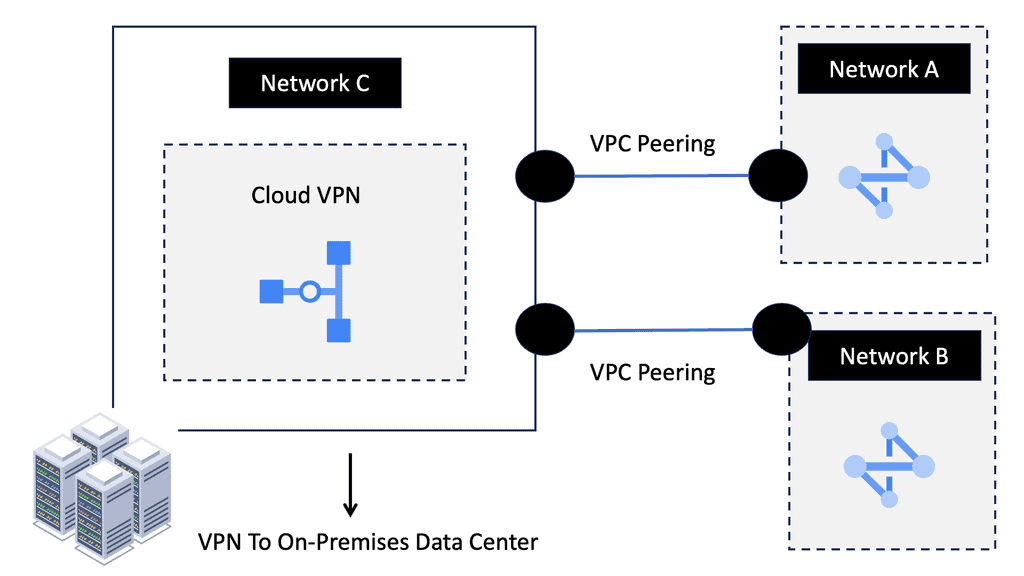
Firewall traffic flow

Network Address Translation (NAT) modifies network address information in IP packet headers while in transit across a traffic routing device. NAT plays a crucial role in conserving IP addresses, enabling multiple devices within a private network to share a single public IP address. Additionally, NAT provides an extra layer of security by hiding internal IP addresses and making them inaccessible from external sources.

By combining ASA Firewall with NAT, organizations can achieve enhanced security and network optimization. The benefits include:

1. Enhanced Security: ASA Firewall protects networks from unauthorized access, malware, and other cyber threats. NAT adds an extra layer of security by concealing internal IP addresses, making it difficult for attackers to target specific devices.

2. IP Address Conservation: NAT allows organizations to conserve public IP addresses by using private IP addresses internally. This is particularly useful in scenarios where the number of available public IP addresses is limited.

3. Increased Network Flexibility: ASA Firewall and NAT enable organizations to establish secure connections between network segments, ensuring controlled access and improved network flexibility.

Guide on ASA failover: 

In this lab, we will address the Active / Standby ASA configuration. We know that the ASA supports active/standby failover, which means one ASA becomes the active device and handles everything while the backup ASA is the standby device. For something to happen, there needs to be a failure event

In our example, ASA1 is ( was ) the primary, and ASA2 is the standby. I disconnected the switch links connected to Gi0//0 on ASA1, triggering the failover event. The screenshot shows the SCPS protocol exchanged between the two ASA nodes. The hello packets are exchanged between active and standby to detect failures using messages sent using IP protocol 105. IP protocol 105 refers to SCPS (Space Communications Protocol Standards).”

The failover mechanism is stateful, meaning the active ASA sends all stateful connection information to the standby ASA. This includes TCP/UDP states, NAT translation tables, ARP tables, and VPN information.

ASA Failover

Highlighting Cisco ASA Failover

The Cisco ASA failover is the high availability mechanism that mainly provides redundancy rather than capacity scaling. While Active/Active failover can help distribute traffic load across a failover pair or devices, its scalability has significant practical implications. With this design, we can leverage failover to group identical ASA appliances or modules into a fully redundant firewall entity with centralized configuration management and stateful session replication ( if needed ).

When one unit in the failover pair can no longer pass transit traffic, its identical peer seamlessly assumes firewall functionality with minimal impact on traffic flows. This type of firewalling design is helpful for an active active data center design.

Cisco ASA failover
Diagram: Cisco ASA failover. Source Grandmetric

Unit Roles and Functions in Firewall Failover

If configuring a firewall failover pair, designate one unit as primary and the other as secondary. The roles are statically configured and do not change during failover. The failover subsystem could use this designation to resolve some operational conflicts. Still, either the primary or secondary units may pass transit traffic while in an active role while their peers remain on standby. Depending on the operational state of the failover pair, dynamic active and standby roles pass between the statically defined primary and secondary units.

Guide: ASA Failover 

Cisco ASA firewalls are often essential network devices. Our company uses them for (remote access) VPNs, NAT/PAT, filtering, and more. Since they’re so important, having a second ASA if the first fails is a good idea. It supports active/standby failover, which means one ASA is the active device, handling everything, while the backup ASA is the standby. Without a failing active ASA, it doesn’t do anything.

Stateful failover means all stateful connection information is sent from the active ASA to the standby ASA. It includes TCP/UDP states, NAT translation tables, ARP tables, and VPN information. Your users won’t notice anything if the active ASA fails because the standby ASA has all the connection information…

If you want to use failover, you must meet the following requirements:

  1. The platform must be the same, for example, 2x ASA 5510 or 2x ASA 5522.
  2. Hardware must be identical: same number and type of interfaces. There must be the same amount of flash memory and RAM.
  3. There are two operating modes: routed and transparent and single and multiple contexts.
  4. The license must be the same, including the number of VPN peers, encryption, etc.
  5. License correctly issued. ASA 5510 is an example of a “lower” model that requires Security Plus licenses for failover

Adaptive Security Appliance: ASA Failover

A failover group for ASA’s high availability consists of identical ASAs connected via a dedicated failover link and an optional state link. Two failover modes, Active / Standby or Active / Active, work in Routed and Transparent modes. Depending on the IOS version, you can use a mixture of routed and transparent modes per context.

There are two types of Cisco ASA failover: Active/Standby failover and Active/Active failover.

Active / Standby

In an Active/Standby failover configuration, the primary unit handles all traffic while the secondary unit remains idle, continuously monitoring the primary unit’s status. If the primary unit fails, the secondary unit becomes the new active unit. This failover process occurs seamlessly, ensuring uninterrupted network connectivity and minimal downtime.

Active / Standby: One-forwarding path and active ASA. The standby forwards traffic when the active device fails over. Traffic is not evenly distributed over both units. Active / standby uses single or multiple context modes. Failover allows two firewall units to operate in hot standby mode.

For two units to operate as a firewall failover pair, their hardware and software configurations must be identical (flash disk and minor software version differences are allowed for zero downtime upgrade of a failover pair). One firewall unit is designated as primary and another as secondary, and by default, the primary unit receives the active role, and the secondary receives the standby role.

Active / Active for context groups

Active/Active failover, as the name suggests, allows both Cisco ASA firewalls to handle network traffic simultaneously actively. Each firewall can have its own set of interfaces and IP addresses, providing load balancing and increased throughput. In a failure, the remaining active firewall takes over the failed unit’s responsibilities, ensuring uninterrupted network services.

Active / Active for context groups: This feature is not supported in single context mode and is only available in multiple context mode. When configuring failover, it is mandatory to set both firewalls in single or multiple context modes simultaneously, with multiple context modes supporting a unique failover function known as Active/Active failover.

With Active/Active failover, the primary unit is active for the first group of security contexts and standby for the second group. In contrast, the secondary unit is active for the second group and standby for the first group. Only two failover groups are supported because only two ASAs are within a failover pair, and the admin context is always a group one member.

Both ASAs forward simultaneously by splitting the context into logical failover groups. Still, technically active / standby. It is not like the Gateway Load Balancing Protocol ( GLBP ). Two units do not forward for the same context at the same time.

ASA failover
Diagram: ASA failover.

It permits a maximum of two failover groups. For example, one group was active on the primary ASA, and another was active on the secondary ASA. Active / Active failover occurs in a group and not on a system basis.

Upon failover event, either by primary unit or context group failure, the secondary takes over the primary IP and Media Access Control Address ( MAC ) address and begins forwarding traffic immediately. The failover event is seamless; no change in IP or MAC results in zero refreshes to Address Resolution Protocol ( ARP ) tables at Layer 3 hosts. If the failover changed MAC addresses, all other Layer 3 devices on the network would have to flush their ARP tables.

**ASA high availability: Type of firewall failover**

For ASA high availability, there are two types of failovers are available

  1. Stateful failover and
  2. Stateless failover.

Cisco ASA Failover: Stateless failover

The default mode is Stateless; no state/connection information is maintained, and upon failover, existing connections are dropped and must be re-established. It uses a dedicated failover link to poll each other. Upon failover, which can be manual or detected, the unit changes roles, and standby assumes the IP and MAC of the primary unit.

Cisco ASA Failover: Stateful failover

Failover operates statelessly by default. The active unit only synchronizes its configuration with the standby device in this configuration. After a failover event, all stateful flow information remains local to the active ASA, so all connections must be re-established. In most high-availability configurations, stateful failover is required to preserve ASA processing resources. You must configure a stateful failover link to communicate state information to the standby ASA, as discussed in the “Stateful Link” section. When stateful replication is enabled, an active ASA synchronizes the following additional information to the standby peer.

Stateful table for TCP and UDP connections. Certain short-lived connections are not synchronized by default by ASA to preserve processing resources. For example, unless you configure the failover replication http command, HTTP connections over TCP port 80 remain stateless.

In the same way, ICMP connections synchronize only in Active/Active failover scenarios with configured Asymmetric Routing (ASR) groups. The maximum connection setup rate supported by the particular ASA platform may be reduced by up to 30 percent when stateful replication is enabled for all connections.

ASA stateful failover: Pass state/connection

Stateful failover: Both units pass state/connection information to each other. Connection information could be Network Address Translation ( NAT ) tables, TCP / UDP connection states, IPSEC SA, and ARP tables. The active unit constantly replicates the state table. Whenever a new connection is added to the table, it’s copied to the standby unit. It is processor-intensive, so you need to understand the design requirements.

Does your environment need stateful redundancy? Does it matter if users must redial or establish a new AnyConnect session? Stateful failover requires a dedicated “stateful failover link.” The stateless failover link can be used, but separating these functions is recommended.

Dynamic routing protocols are maintained with stateful failover. The routes learned by the active unit are carried across to the Routing Information Base ( RIB ) table on the standby unit. However, hypertext Transfer Protocol ( HTTP ) connections are short-lived, and HTTP clients usually retry failed connection attempts. As a result, by default, the HTTP state is not replicated. The command failover replication HTTP enables HTTP connections in replication.

ASA failover
Diagram: Checking ASA failover status

Firewall Failover Link

The failover link is for Link-Local communication between ASAs and determines the status of each ASA. Layer 2 polling via HELLO Keepalives transmitted and configurations synchronized. Have the connecting switch ports in port fast mode, ensuring if a flap of the link occurs, no other Layer 2 convergence will affect the failover convergence.

For redundancy purposes, use port channels and do not use the same link for stateless connectivity. It is recommended that the failover and data links be connected through different physical paths. Failover links should not use the same switch as the data interfaces, as the state information may generate excessive traffic. In addition, you don’t want the replication of the state information to interfere with normal Keepalives.

Failover link connectivity

The failover link can be connected directly or by an Ethernet switch. If the failover link connects via an ethernet switch, use a separate VLAN with no other devices in that Layer 2 broadcast domain. ASA supports Auto-MDI/MDIX, enabling crossover or straight-through cable. MDI-MDIX automatically detects the cable type and swaps transmit/receive pairs to match the cable seen.

ASA’s high availability and asymmetric routing

Asymmetric routing means that a packet does not follow the same logical path both ways (outbound client-to-server traffic uses one path, and inbound server-to-client uses another path). Because firewalls track connection states and inspect traffic, asymmetric routing is not firewall-friendly by default, traffic is dropped, and TCP traffic is significantly affected.

The problem with asymmetric traffic flows is that if ASA receives a packet without connection/state information, it will drop it. The issue may arise in the case of an Active / Active design connected to two different service providers. It does not apply to Active / Standby as the standby is not forwarding traffic and, as a result, will not receive returning traffic sent from the active unit. It is possible to allow asymmetrically routed packets by assigning similar interfaces to the same ASR group.

Asymmetric Traffic
Diagram: Asymmetric traffic.

ASA Failover and Traffic Flow Considerations

  • An outbound session exists to ISP-A through the Primary-A context.

  • In this instance, return traffic flows from ISP-B to Primary-B context.

  • Traffic dropped as Primary-B does not have state information for the original flow.

  • However, due to interfaces configured in the same ASR Group, session information for the original outbound flow has been replicated to the Primary-B context. 

  • Layer 2 header rewritten and traffic redirected to Primary-B. Resulting in asymmetrically routed packets being restored to the correct interface.

 Stateful failover and HTTP replication are required.

Although in all real deployments, you should avoid asymmetric routing (with or without a firewall in the path), there are certain cases when this is required or when you need more control. If a firewall is in the path, there are several options to still allow traffic through:

  • If outbound traffic transits the firewall, but inbound traffic does not, use TCP state bypass for the respective connection or use static NAT with nailed option (effectively disables TCP state tracking and sequence checking for the connection).
  • If both outbound and inbound traffic transit the firewall but on different interfaces, use the exact solutions as above.
  • If outbound traffic transits one context of the ASA and inbound traffic transits another context of the ASA, use ASR groups; this applies only for multi-context mode and requires active-active stateful failover configured.

Unit Monitoring

The failover link determines the health of the overall unit. HELLO packets are sent over the failover link. The lack of three consecutive HELLOs causes ASA to send an additional HELLO packet out of ALL data interfaces, including the failover link, ruling out the failure of the actual failover link.

The ASA’s action depends on the additional HELLO packets. No action occurs if a response is received over the failover or data links, and failover actions occur if no response is received on any of the links. With interface monitoring, the number of monitored interfaces depends on the IOS version. It would help if you always tried to monitor essential interfaces.

A final note on ASA’s high availability: In an IPv6 world, ASA uses IPv6 neighbor discovery instead of ARP for its health monitoring tests. If it has to broadcast to all nodes, it uses IPv6 FE02::1. FE02::1 is an all-IPv6 speakers-multicast group.

Closing Points on ASA Failover

ASA failover is a high-availability feature provided by Cisco’s Adaptive Security Appliance solutions. It ensures continuous network operation by allowing a backup ASA to take over traffic handling in case the primary ASA fails. This is particularly important for businesses that can’t afford any interruption in their network services.

There are two primary types of ASA failover configurations: Active/Standby and Active/Active.

– **Active/Standby**: In this setup, one ASA unit is actively handling traffic while the other remains on standby, ready to take over if the active unit fails. This is the most common configuration due to its simplicity and effectiveness.

– **Active/Active**: This configuration allows both ASA units to actively handle traffic, providing load balancing and redundancy. It’s more complex to set up and manage, but it can offer better resource utilization and performance.

Implementing ASA failover involves several key steps:

1. **Hardware and Software Requirements**: Ensure that both ASA units are identical in terms of hardware and software versions. Mismatched devices can lead to failover issues.

2. **Configuration Synchronization**: Use the failover link to synchronize configuration settings between the primary and secondary ASA units. This ensures that both devices have the same security policies and rules.

3. **Monitoring and Testing**: Regularly monitor the failover setup to ensure it’s functioning correctly. Conduct failover tests to verify that the secondary ASA can seamlessly take over traffic handling when needed.

Summary: ASA Failover

In today’s fast-paced digital landscape, network downtime can be catastrophic for businesses. As companies rely heavily on their network infrastructure, having a robust failover mechanism is crucial to ensure uninterrupted connectivity. In this blog post, we delved into the world of ASA failover and explored its importance in achieving network resilience and high availability.

Understanding ASA Failover

ASA failover refers to the capability of Cisco Adaptive Security Appliances (ASAs) to automatically switch to a backup unit in the event of a primary unit failure. It creates a seamless transition, maintaining network connectivity without any noticeable interruption. ASA failover operates in Active/Standby and Active/Active modes.

Active/Standby Failover Configuration

In an Active/Standby failover setup, one ASA unit operates as the active unit, handling all traffic. In contrast, the standby unit remains hot, ready to take over instantly. This configuration ensures network continuity even if the active unit fails. The standby unit constantly monitors the health of the active unit, ensuring a swift failover when needed.

Active/Active Failover Configuration

Active/Active failover allows both ASA units to process traffic simultaneously, distributing the load and maximizing resource utilization. This configuration is ideal for environments with high traffic volume and resource-intensive applications. In a failure, the remaining active unit seamlessly takes over the entire workload, offering uninterrupted connectivity.

Configuring ASA Failover

Configuring ASA failover involves several steps, including interface and IP address configuration, failover link setup, and synchronization settings. Cisco provides a comprehensive set of commands to configure ASA failover efficiently. Following best practices and thoroughly testing the failover configuration is essential to ensure its effectiveness during real-world scenarios.

Monitoring and Troubleshooting Failover

Proactive monitoring and regular testing are essential to maintain the reliability and effectiveness of ASA failover. Cisco ASA provides various monitoring tools and commands to monitor failover status, track synchronization, and troubleshoot any issues that may arise. Establishing a monitoring routine and promptly address any detected problems to prevent potential network disruptions is crucial.

Conclusion:

ASA failover is a critical component of network resilience and high availability. By implementing an appropriate failover configuration, organizations can minimize downtime, ensure uninterrupted connectivity, and provide a seamless experience to their users. Whether it is Active/Standby or Active/Active failover, the key lies in proper configuration, regular monitoring, and thorough testing. Invest in ASA failover today and safeguard your network against potential disruptions.

Context Firewall

Context Firewall

Context Firewall

In today's digital landscape, the importance of data security cannot be overstated. Organizations across various sectors are constantly striving to protect sensitive information from malicious actors. One key element in this endeavor is the implementation of context firewalls.

In this blogpost, we will delve into the concept of context firewalls, their benefits, challenges, and how businesses can effectively navigate this security measure.

A context firewall is a sophisticated cybersecurity measure that goes beyond traditional firewalls. While traditional firewalls focus on blocking specific network ports or IP addresses, context firewalls take into account the context and content of network traffic. They analyze the data flow, examining the behavior and intent behind network requests, ensuring a more comprehensive security approach.

Context firewalls play a crucial role in enhancing digital security by providing advanced threat detection and prevention capabilities. By examining the context and content of network traffic, they can identify and block malicious activities, including data exfiltration attempts, unauthorized access, and insider attacks. This proactive approach helps defend against both known and unknown threats, adding an extra layer of protection to your digital assets.

The advantages of context firewalls are multi-fold. Firstly, they enable granular control over network traffic, allowing administrators to define specific policies based on context. This ensures that only legitimate and authorized activities are allowed, reducing the risk of unauthorized access or data breaches.

Secondly, context firewalls provide real-time visibility into network traffic, empowering security teams to identify and respond swiftly to potential threats. Lastly, these firewalls offer advanced analytics and reporting capabilities, aiding in compliance efforts and providing valuable insights into network behavior.

Highlights: Context Firewall

The Role of Firewalling

1- Firewalls protect inside networks from unauthorized access from outside networks. Firewalls can also separate inside networks, for example, by keeping human resources networks from user networks.
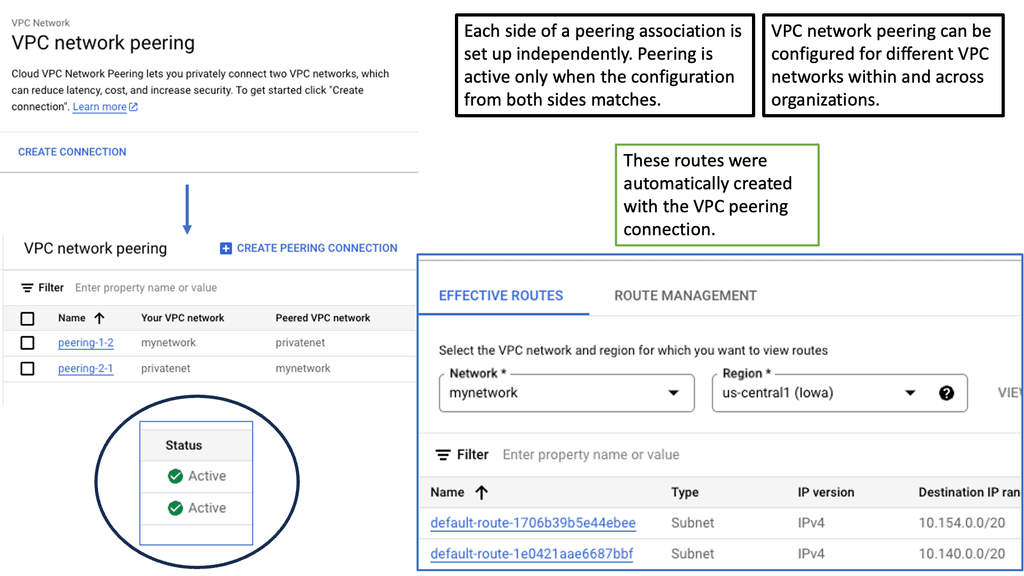
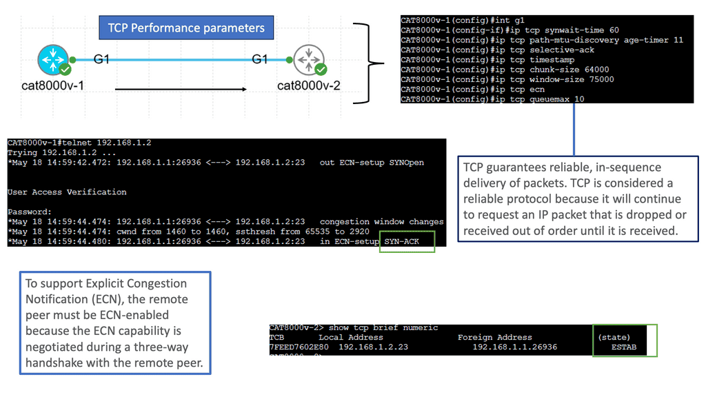
2- Demilitarized zones (DMZs) are networks behind firewalls that allow outside users to access network resources such as web or FTP servers. A firewall only allows limited access to the DMZ, but since the DMZ only contains the public servers, an attack there will only affect the servers and not the rest of the network.

3- Additionally, you can restrict access to outside networks (for example, the Internet) by allowing only specific addresses out, requiring authentication, or coordinating with an external URL filtering server.

4- Three types of networks are connected to a firewall: the outside network, the inside network, and a DMZ, which permits limited access to outside users. These terms are used in a general sense because the security appliance can configure many interfaces with different security policies, including many inside interfaces, many DMZs, and even many outside interfaces.


**Key Firewalling Considerations**

– Understanding Firewalls: Firewalls serve as a protective barrier between a trusted internal network and an external network, such as the internet. They monitor and control incoming and outgoing network traffic based on predefined security rules. Firewalls can be categorized into several types based on their characteristics and deployment methods.

– Exploring Traditional Firewalls: Traditional firewalls, also known as packet-filtering firewalls, operate at the network layer (Layer 3) of the OSI model. They examine individual packets of data and determine whether to allow or block them based on predetermined rules. These firewalls analyze IP addresses, ports, and protocols to make filtering decisions.

– Next-Generation Firewalls: As cyber threats have evolved, so have firewalls. Next-generation firewalls (NGFWs) go beyond packet filtering and integrate additional security features. They provide advanced capabilities such as deep packet inspection, intrusion prevention, and application-level filtering. NGFWs offer enhanced visibility and control over network traffic, helping organizations combat sophisticated attacks more effectively.

– Introducing Context Firewalling: Context firewalling takes network security to a whole new level. Unlike traditional firewalls that focus on individual packets or NGFWs that analyze application-layer data, context firewalls operate at the session layer (Layer 5) of the OSI model. They establish context-aware security policies by considering the complete network session, including user identity, behavior, and device posture.

Note: Context firewalling offers several advantages over traditional and NGFW approaches. By considering contextual information, these firewalls can make more informed decisions about network access, reducing false positives and enhancing security. Context firewalls also enable dynamic policy enforcement based on real-time user and device behavior, adapting to the evolving threat landscape.

Example: Google Cloud Armor Firewall

### Understanding Context-Aware Firewall

At the heart of Google Cloud Armor is its context-aware firewall, a revolutionary feature that leverages machine learning and AI to enhance threat detection and mitigation. Unlike traditional firewalls that rely on static rules, a context-aware firewall analyzes patterns and behaviors, adapting to emerging threats in real-time. This dynamic approach allows businesses to protect their applications against sophisticated attacks, including DDoS, SQL injection, and cross-site scripting, without compromising performance.

### Key Features of Google Cloud Armor

Google Cloud Armor offers a suite of powerful features designed to safeguard your digital assets:

– **DDoS Protection:** Automatically detects and mitigates large-scale DDoS attacks, ensuring your services remain uninterrupted.

– **Adaptive Security Policies:** Create and manage custom security policies tailored to your business needs, with the flexibility to adjust as threats evolve.

– **Traffic Filtering:** Filter incoming traffic based on IP addresses, geographical location, or custom-defined criteria, allowing you to block malicious actors effectively.

– **Real-Time Visibility:** Gain insights into your security posture with detailed logs and reports that help you identify and respond to threats swiftly.

### Implementing Google Cloud Armor

Deploying Google Cloud Armor is straightforward, thanks to its seamless integration with other Google Cloud services. Whether your applications are hosted on Google Cloud Platform or in a hybrid environment, Google Cloud Armor provides consistent protection across the board. By utilizing pre-configured security templates or customizing your policies, you can quickly set up a robust defense tailored to your specific requirements.

Context Firewalling

Context firewalls provide several advantages over traditional firewalls. By inspecting the content of the network traffic, they can identify and block unauthorized access attempts, malicious code, and other potential threats. This proactive approach significantly enhances the security posture of an organization or an individual, reducing the risk of data breaches and unauthorized access.

Context firewalls are particularly effective in protecting against advanced persistent threats (APTs) and targeted attacks. These sophisticated cyber attacks often exploit application vulnerabilities or employ social engineering techniques to gain unauthorized access. By analyzing the context of network traffic, context firewalls can detect and block such attacks, minimizing the potential damage.

Key Features of Context Firewalls:

Context firewalls have various features that augment their effectiveness in securing the digital environment. Some notable features include:

1. Deep packet inspection: Context firewalls analyze the content of individual packets to identify potential threats or unauthorized activities.

2. Application awareness: They understand the specific protocols and applications being used, allowing them to apply tailored security policies.

3. User behavior analysis: Context firewalls can detect anomalies in user behavior, which can indicate potential insider threats or compromised accounts.

4. Content filtering: They can restrict access to specific websites or block certain types of content, ensuring compliance with organizational policies and regulations.

5. Threat intelligence integration: Context firewalls can leverage threat intelligence feeds to stay updated on the latest known threats and patterns of attack, enabling proactive protection.

Context firewalls provide organizations and individuals with a robust defense against increasing cyber threats. By analyzing network traffic content and applying security policies based on specific contexts, context firewalls offer enhanced protection against advanced threats and unauthorized access attempts.

With their deep packet inspection, application awareness, user behavior analysis, content filtering, and threat intelligence integration capabilities, context firewalls play a vital role in safeguarding our digital environment. As the cybersecurity landscape continues to evolve, investing in context firewalls should be a priority for anyone seeking to secure their digital assets effectively.

Example Firewalling with Linux

Understanding UFW Firewall

The UFW (Uncomplicated Firewall) is a user-friendly interface built on top of the iptables firewall system. It is designed to simplify configuring and managing firewall rules without compromising security. By leveraging iptables, UFW provides a convenient way to secure your network from unauthorized access, malicious activities, and potential threats.

Implementing a UFW firewall offers several notable advantages. First, it provides a straightforward and intuitive command-line interface, making it accessible even for users with limited technical expertise. Second, UFW supports IPv4 and IPv6, ensuring compatibility across network protocols.

Third, UFW allows for easy rule configuration, such as defining specific ports, IP addresses, or even application profiles, giving you fine-grained control over network access. Lastly, UFW integrates seamlessly with other security tools and services, enhancing the overall protection of your network infrastructure.

Understanding Multi-Context Firewalls

A: – A multi-context firewall is a security device that creates multiple virtual firewalls within a single physical firewall appliance. Each virtual firewall, known as a context, operates independently of its security policies, interfaces, and routing tables. This segregation enables organizations to consolidate their network security infrastructure while maintaining strong isolation between network segments.

B: – Organizations can ensure that traffic flows are strictly controlled and isolated by creating separate contexts for different departments, business units, or even customers. This segmentation prevents lateral movements in case of a breach, limiting the potential impact on the entire network.

**Security Context – Partitioning** 

By partitioning a single security appliance, multiple security contexts can be created. Each context has its own security policy, interface, and administrator. Having multiple contexts is similar to having multiple standalone devices. Routing tables, firewalls, intrusion prevention systems, and management are all supported in multiple context modes. Dynamic routing protocols and VPNs are not supported.

**Context Firewall Operation**

A context firewall is a security system designed to protect a computer network from malicious attacks. It blocks, monitors, and filters network traffic based on predetermined rules.  Multiple Context Mode divides Adaptive Security Appliance ( ASA ) into multiple logical devices, known as security contexts.

Each security context acts like one device and operates independently of others. It has security policies and interfaces similar to Virtual Routing and Forwarding ( VRF ) on routers. You are acting like a virtual firewall. The context firewall offers independent data planes ( one for each security context ), but one control plane controls all of the individual contexts.

**Use Cases**

Use cases are large enterprises requiring additional ASAs – hosting environments where service providers want to sell security services ( managed firewall service ) to many customers – one context per customer. So, in summary, the ASA firewall is a stateful inspection firewall that supports software virtualization using firewall contexts. Every context has routing, filtering/inspection, address translation rules, and assigned IPS sensors.

When would you use multiple security contexts? 

  • A network that requires more than one ASA. So, you may have one physical ASA and need additional firewall services.
  • You may be a large service provider offering security services that must provide each customer with a different security context.
  • An enterprise must provide distinct security policies for each department or user and require a different security context. This may be needed for compliance and regulations.

Google Cloud Security FortiGate

Understanding FortiGate and its Capabilities

FortiGate is an industry-leading network security appliance that provides comprehensive threat protection, intrusion prevention, and advanced firewall capabilities. With its advanced security features and centralized management, FortiGate ensures a robust defense against cyber threats, offering enhanced visibility and control over your Google Compute resources.

FortiGate seamlessly integrates with Google Cloud, allowing you to extend your security policies and controls to your Google Compute instances. By deploying FortiGate as a virtual machine on Google Compute Engine, you can create a secure perimeter around your cloud infrastructure, safeguarding it from both external and internal threats.

– Advanced Threat Protection: FortiGate provides real-time threat intelligence and advanced threat protection capabilities, such as intrusion prevention, antivirus, web filtering, and application control. These features help identify and mitigate potential security risks, ensuring the integrity of your Google Compute resources.

– Secure Remote Access: With FortiGate, you can establish secure remote access VPN connections to your Google Compute instances. This enables authorized users to securely access your cloud resources, while ensuring that unauthorized access attempts are blocked.

– Scalability and Performance: FortiGate is designed to handle high network traffic volume without compromising performance. It offers scalable solutions that can adapt to the dynamic needs of your growing Google Compute infrastructure.

– Centralized Management: FortiGate provides a centralized management platform, allowing you to efficiently manage and monitor your security policies across your entire Google Compute environment. This simplifies the management process and ensures consistent security across all instances.

Related: Before you proceed, you may find the following posts helpful:

  1. Virtual Device Context
  2. Virtual Data Center Design
  3. Distributed Firewalls
  4. ASA Failover
  5. OpenShift Security Best Practices
  6. Network Configuration Automation

Context Firewall

Highlighting the firewall

A firewall is a hardware or software, aka virtual firewalls filtering device, that implements a network security policy and protects the network against external attacks. A packet is a unit of information routed between one point and another over the network. The packet header contains a wealth of data such as source, type, size, origin, and destination address information. As the firewall acts as a filtering device, it watches for traffic that fails to comply with the rules by examining the contents of the packet header.

Firewalls can concentrate on the packet header, the packet payload, or both, and possibly other assets, depending on the firewall types. Most firewalls focus on only one of these. The most common filtering focus is on the packet’s header, with a packet’s payload a close second. The following diagram shows the two main firewall categories stateless and stateful firewalls.

Firewall types
Diagram: Firewall types. Source is IPwithease
  • Stateful Firewall:

A stateful firewall is a type of firewall technology that is used to help protect network security. It works by keeping track of the state of network connections and allowing or denying traffic based on predetermined rules. Stateful firewalls inspect incoming and outgoing data packets and can detect malicious traffic. They can also learn which traffic is regular for a particular environment and block any traffic that does not conform to expected patterns.

  • Stateless Firewall

A stateless firewall is a network security device that monitors and controls incoming and outgoing network traffic based on predetermined security rules. It does this without keeping any record or “state” of past or current network connections. Controlling traffic based on source and destination IP addresses, ports, and protocols can also prevent unauthorized access to the network.

data center firewall

Stateful vs. Stateless Firewall

**Stateful Firewall**

A stateful firewall, also known as a dynamic packet filtering firewall, operates at the OSI model’s network layer (Layer 3). Unlike stateless firewalls, which inspect individual packets in isolation, stateful firewalls maintain knowledge of the connection state and context of network traffic. This means that stateful firewalls make decisions based on the characteristics of individual packets and the history of previous packets exchanged within a session.

How Stateful Firewalls Work:

Stateful firewalls keep track of the state of network connections by creating a state table, also known as a stateful inspection table. This table stores information about established connections, including the source and destination IP addresses, port numbers, sequence numbers, and other relevant data. By comparing incoming packets against the information in the state table, stateful firewalls can determine whether a packet is part of an established session or a new connection attempt.

Advantages of Stateful Firewalls:

1. Enhanced Security: Stateful firewalls offer a higher level of security by understanding the context and state of network traffic. This enables them to detect and block suspicious or unauthorized activities more effectively.

2. Better Performance: By maintaining a state table, stateful firewalls can quickly process packets without inspecting each packet individually. This results in improved network performance and reduced latency compared to stateless firewalls.

3. Granular Control: Stateful firewalls provide administrators with fine-grained control over network traffic by allowing them to define rules based on network states, such as allowing or blocking specific types of connections.

**Stateless Firewall**

In contrast to stateful firewalls, stateless firewalls, also known as packet filtering firewalls, operate at the network and transport layers (Layers 3 and 4). These firewalls examine individual packets based on predefined rules and criteria without considering the context or history of the network connections.

How Stateless Firewalls Work:

Stateless firewalls analyze incoming packets based on criteria such as source and destination IP addresses, port numbers, and protocol types. Each packet is evaluated independently, without referencing the packets before or after. If a packet matches a rule in the firewall’s rule set, it is allowed or denied based on the specified action.

Advantages of Stateless Firewalls:

1. Simplicity: Stateless firewalls are relatively simple in design and operation, making them easy to configure and manage.

2. Speed: Stateless firewalls can process packets quickly since they do not require the overhead of maintaining a state table or inspecting packet history.

3. Scalability: Stateless firewalls are highly scalable as they do not store any connection-related information. This allows them to handle high traffic volumes efficiently.

**Next-generation Firewalls**

Next-generation firewalls (NGFWs) would carry out the most intelligent filtering. They are a type of advanced cybersecurity solution designed to protect networks and systems from malicious threats.

They are designed to provide an extra layer of protection beyond traditional firewalls by incorporating features such as deep packet inspection, application control, intrusion prevention, and malware protection. NGFWs can conduct deep packet inspections to analyze network traffic contents and observe traffic patterns.

This feature allows NGFWs to detect and block malicious packets, preventing them from entering the system and causing harm. The following diagram shows the different ways a firewall can be deployed. The focus of this post will be on multi-context mode. An example would be the Cisco Secure Firewall.

context firewall
Diagram: Context Firewall.

Guide: ASA Basics.

In the following lab guide, you can see we have an ASA working in routed mode. In routed mode, the ASA is considered a router hop in the network. Each interface that you want to route between is on a different subnet. You can share Layer 3 interfaces between contexts.

Traditionally, a firewall is a routed hop and acts as a default gateway for hosts that connect to one of its screened subnets. On the other hand, a transparent firewall is a Layer 2 firewall that acts like a “bump in the wire” or a “stealth firewall” and is not seen as a router hop to connected devices. 

The ASA considers the state of a packet when deciding to permit or deny the traffic. One enforced parameter for the flow is that traffic enters and exits the same interface. The ASA drops any traffic for an existing flow that enters a different interface. Take note of the command: same-security-traffic permit inter-interface.

Cisco ASA configuration
Diagram: Cisco ASA Configuration

Multi-Context Firewall Types

Contexts are generally helpful when different security policies are applied to traffic flows. For example, the firewall might protect multiple customers or departments in the same organization. Other virtualization technologies, such as VLANs or VRFs, are expected to be used alongside the firewall contexts; however, the firewall contexts have significant differences from the VRFs seen in the IOS routers.

**Context Configuration Files**

For each context, the ASA includes a configuration that identifies the security policy, interfaces, and settings that can be configured. Context configurations can be stored in flash memory or downloaded from a TFTP, FTP, or HTTP(S) server.

**System configuration**

A system administrator configures the configuration location, interfaces, and other operating parameters of contexts in the system configuration to add and manage contexts. The startup configuration looks like this. Basic ASA settings are identified in the system configuration. There are no network interfaces or settings in the system configuration; when the system needs to access network resources (such as downloading contexts from the server), it uses an admin context. The system configuration has only a specialized failover interface for failover traffic.

**Admin context configuration**

Admin contexts are no different from other contexts. Users who log into the admin context have administrator rights and can access all contexts and the system. No restrictions are associated with the admin context, which can be used just like any other context. However, you may need to restrict access to the admin context to appropriate users because logging into the admin context grants administrator privileges over all contexts.

Flash memory must contain the admin context, not remote storage. When you switch from single to multiple modes, the admin context is configured in an internal flash memory file called admin.cfg. You can change the admin context if you do not wish to use admin.cfg as the admin context.

Steps: Turning a firewall into multiple context mode:

To turn the firewall to the multiple contexts mode, you should enter the global command mode multiple when logged in via the console port (you may do this remotely, converting the existing running configuration into the so-called admin context, but you risk losing connection to the box); this will force the mode change and reload the appliance.

If you connect to the appliance on the console port, you are logging in to the system context; the sole purpose of this context is to define other contexts and allocate resources to them. 

System Context

Used for console access. Create new contexts and assign interfaces to each context.

Admin Context

Used for remote access, either Telnet or SSH. Remote supports the change to command.

User Context

Where the user-defined multi-context ( virtual firewall ) lives.

 Multi Context Mode
Diagram: Multi Context Mode

Your first action step should be to define the admin context; this special context allows logging into the firewall remotely (via ssh, telnet, or HTTPS). This context should be configured first because the firewall won’t let you create other contexts before designating the admin context using the global command admin-context <name>.

Then you can define additional contexts if needed using the command context <name> and allocate physical interfaces to the contexts using the context-level command allocate-interface <physical-interface> [<logical-name>].

Each firewall context is assigned.

Interfaces

Physical or 802.1Q subinterface. Possible to have a shared interface where contexts share interfaces.

Resource Limits

Number of connections, hosts, xlates

Firewall Policy

Different MPF inspections, NAT translations, etc. for each context.

The multi-context mode has many security contexts acting independently. Sharing multiple contexts with a single interface confuses determining which context to send packets to. ASA must associate inbound traffic with the correct context. Three options exist for classifying incoming packets.

Unique Interfaces

One-to-one pairing with either physical link or sub-interfaces ( VLAN tags ).

Shared Interface

Unique Virtual MAC Addresses per virtual context, either auto-generate or manual set.

NAT Configurations

Not common.

The Basics of ASA Packet Classification

ASA packet classification is the process of categorizing network packets based on various criteria. These criteria include source and destination IP addresses, port numbers, protocol types, and more. By classifying packets, the ASA firewall can make informed decisions on how to handle them, whether it’s allowing or denying their passage.

1- Access Control Lists (ACLs)

ACLs are a fundamental tool for ASA packet classification. They provide a granular level of control over network traffic by defining rules that determine whether packets should be permitted or denied. ACLs are typically configured based on specific criteria such as IP addresses, port numbers, and protocols. Understanding how to create and optimize ACLs is crucial for effective packet classification.

2- Modular Policy Framework (MPF)

MPF takes packet classification to the next level by introducing a more flexible and sophisticated approach. It allows administrators to define policies that can encompass multiple ACLs and apply them to different interfaces or traffic flows. With MPF, packet classification becomes more dynamic and adaptable, enabling better network management and security.

3- Advanced Packet Classification Techniques

Beyond the basics, ASA offers advanced packet classification techniques that enhance network performance and security. These techniques include packet inspection, deep packet inspection (DPI), and application layer protocol inspection. By analyzing packet payloads and application-layer data, ASA can make more intelligent decisions, leading to improved network efficiency and threat prevention.

4- ASA Packet Classification: Mulit-Context

Packets are also classified differently in multi-context firewalls. For example, in multimode configuration, interfaces can be shared between contexts. Therefore, the ASA must distinguish which packets must be sent to each context.

The ASA categorizes packets based on three criteria:

  1. Unique interfaces – 1:1 pairing with a physical link or sub-interfaces (VLAN tags)
  2. Unique MAC addresses – shared interfaces are assigned Unique Virtual Mac addresses per virtual context to alleviate routing issues, which complicates firewall management
  3. NAT configuration: If unique MAC addresses are disabled, the ASA uses the mapped addresses in the NAT configuration to classify packets.

Starting with Point 1, the following figure shows multiple contexts sharing an outside interface. The classifier assigns the packet to Context B because Context B includes the MAC address to which the router sends the packet.

Context Firewall
Diagram: Context Firewall configuration. Source Cisco.

Firewall context interface details

Unique Interfaces are self-explanatory: there should be unique interfaces for each security context, for example, GE 0/0.1 Admin Context, GE 0/0.2 Context A, and GE 0/0.3 Context B. Unique interfaces are best practices, but you also need unique routing and IP addressing. This is because each VLAN has its subnet. Transparent firewalls must use unique interfaces.

With Shared Interfaces, contexts MAC addresses classify packets so upstream and downstream routers can send packets to that context. Every security context that shares an interface requires a unique MAC address.

It can be auto-generated ( default behavior ) or manually configured. Manual MAC address assignments take precedence. We share the same outside interface with numerous contexts but have a unique MAC address per context. Use the mac-address auto command under the system context or enter the manual under the interface. Then, we have Network Address Translation ( NAT ) and NAT translation per context for shared interfaces—a less common approach.

Addressing scheme

The addressing scheme in each context is arbitrary when using shared or unique interfaces. Configure 10.0.0.0/8-address space in context A and context B. ASA does not use an IP address to classify the traffic; it uses the MAC address or the physical link. The problem is that the same addressing cannot be used if NAT is used for incoming packet classification. The recommended approach is unique interfaces, not NAT, for classification.

Routing between context

Like route-leaking VRFs, routing between contexts is accomplished by traffic hair-pinning in and out of the interface by pointing static routes to relevant next hops. Designs available to Cascade Contexts for shared firewalls; the default route from one context indicates the inside interface of another context.

Firewall context resource limitations

All security contexts share resources and belong to the default class, i.e., the control plane has no division. Therefore, no predefined limits are specified from one security context to another. However, problems may arise when one security context overwhelms others, consuming too many resources and denying connections to different contexts. In this case, security contexts are assigned to resource classes, and upper limits are set.

The default class has the following limitations:

Telnet sessions5 sessions
SSH sessions5 sessions
IPsec sessions5 sessions
MAC addresses5 sessions
VPN site-to-site tunnels0 sessions

Active/active failover:

Multi-context mode offers Active / Active fail-over per Context. Primary forwards are for one set of contexts, and secondary forwards are for another. Security contexts divide logically into failure groups, a maximum of two failure groups. There are never two active forwarding paths at the same time. One ASA is active for Context A. The second ASA is the standby for Context A. Reversed roles for Context B. 

So, in summary, multi-context mode offers active/active fail-over per context—the primary forwards for one context and the secondary for another. The security contexts divide logically into failure groups, with a maximum of two failure groups. There will always be one active forwarding path at a time. 

Guide: ASA Failover.

The following have two ASAs: ASA1 and ASA2. There is a failover link connecting the two firewalls. ASA1 is the primary, and ASA2 is the backup. ASA failover only occurs when there is an issue; in this case, the links from ASA1 to the switch were down, creating the failover event. Notice the protocol used between the ASA of SCPS from a packet capture.

ASA Failover


Closing Points: Context Firewalling

Context firewalling is a modern approach to network security that goes beyond traditional firewall mechanisms. Unlike conventional firewalls that rely primarily on static rules, context firewalling incorporates dynamic context into its decision-making process. This means that it considers various factors such as user identity, device type, location, and behavior patterns to determine whether to allow or block network traffic. By integrating these contextual elements, context firewalling provides a more nuanced and adaptive security solution.

At its core, context firewalling functions by continuously analyzing the environment in which network requests are made. It employs advanced algorithms and machine learning techniques to assess the legitimacy of each request based on its context. For example, if a user attempts to access sensitive data from an unusual location or device, the context firewalling system can flag this activity as suspicious and take appropriate action. This dynamic evaluation process helps in identifying and mitigating potential threats in real time, thereby enhancing overall security.

One of the primary advantages of context firewalling is its ability to adapt to changing scenarios. Traditional firewalls operate on pre-defined rules, which can become obsolete as new threats emerge. In contrast, context firewalling evolves alongside the digital landscape, offering a proactive defense mechanism. Additionally, by leveraging context, organizations can reduce the likelihood of false positives, allowing legitimate traffic while blocking malicious attempts more accurately.

Context firewalling is particularly beneficial in environments where security must be highly adaptive and responsive. Industries such as finance, healthcare, and e-commerce, which handle sensitive data and are frequently targeted by cyberattacks, can greatly benefit from this approach. By implementing context firewalling, these sectors can ensure that only authorized users and devices can access critical resources, minimizing the risk of data breaches and unauthorized access.

Summary: Context Firewall

In today’s digital age, ensuring the security and privacy of sensitive data has become increasingly crucial. One effective solution that has emerged is the context firewall. This blog post delved into context firewalls, their benefits, implementation, and how they can enhance data security in various domains.

Understanding Context Firewalls

Context firewalls serve as an advanced layer of protection against unauthorized access to sensitive data. Unlike traditional firewalls that filter traffic based on IP addresses or ports, context firewalls consider additional contextual information such as user identity, device type, location, and time of access. This context-aware approach allows for more granular control over data access, significantly reducing the risk of security breaches.

Benefits of Context Firewalls

Implementing a context firewall brings forth several benefits. Firstly, it enables organizations to enforce fine-grained access control policies, ensuring that only authorized users and devices can access specific data resources. Secondly, context firewalls enhance the overall visibility and monitoring capabilities, providing real-time insights into data access patterns and potential threats. Lastly, context firewalls facilitate compliance with industry regulations by offering more robust security measures.

Implementing a Context Firewall

The implementation of a context firewall involves several steps. First, organizations need to identify the context parameters relevant to their specific data environment. This includes factors such as user roles, device types, and location. Once the context parameters are defined, organizations can configure the firewall rules accordingly. Additionally, integrating the context firewall with existing infrastructure and security systems is essential for seamless operation.

Context Firewalls in Different Domains

The versatility of context firewalls allows them to be utilized across various domains. In the healthcare sector, context firewalls can restrict access to sensitive patient data based on factors such as user roles and location, ensuring compliance with privacy regulations like HIPAA. In the financial industry, context firewalls can help prevent fraudulent activities by implementing strict access controls based on user identity and transaction patterns.

Conclusion:

In conclusion, the implementation of a context firewall can significantly enhance data security in today’s digital landscape. By considering contextual information, organizations can strengthen access control, monitor data usage, and comply with industry regulations more effectively. As technology continues to advance, context firewalls will play a pivotal role in safeguarding sensitive information and mitigating security risks.

security

Stateful Inspection Firewall

Stateful Inspection Firewall

Network security is crucial in safeguarding businesses and individuals from cyber threats in today's interconnected world. One of the critical components of network security is a firewall, which acts as a barrier between the internal and external networks, filtering and monitoring incoming and outgoing network traffic. Among various types of firewalls, one that stands out is the Stateful Inspection Firewall.

Stateful Inspection Firewall, also known as dynamic packet filtering, is a security technology that combines the benefits of traditional packet filtering and advanced inspection techniques. It goes beyond simply examining individual packets and considers the context and state of the network connection. Doing so provides enhanced security and greater control over network traffic.

Stateful inspection firewalls boast an array of powerful features. They perform deep packet inspection, scrutinizing not only the packet headers but also the payload contents. This enables them to detect and mitigate various types of attacks, including port scanning, denial-of-service (DoS) attacks, and application-layer attacks. Additionally, stateful inspection firewalls support access control lists (ACLs) and can enforce granular security policies based on source and destination IP addresses, ports, and protocols.

Stateful inspection firewalls maintain a state table that tracks the state of each network connection passing through the firewall. This table stores information such as source and destination IP addresses, port numbers, sequence numbers, and more. By comparing incoming packets against the state table, the firewall can determine whether to permit or reject the traffic. This intelligent analysis ensures that only legitimate and authorized connections are allowed while blocking potentially malicious or unauthorized ones.

Implementing stateful inspection firewalls brings numerous advantages to organizations. Firstly, their ability to maintain session state information allows for enhanced security as they can detect and prevent unauthorized access attempts. Secondly, these firewalls provide improved performance by reducing the processing overhead associated with packet filtering. Lastly, stateful inspection firewalls offer flexibility in handling complex protocols and applications, ensuring seamless connectivity for modern network infrastructures.

Deploying stateful inspection firewalls requires careful planning and consideration. Organizations should conduct a thorough network inventory to identify the optimal placement of these firewalls. They should also define clear security policies and configure the firewalls accordingly. Regular monitoring and updates are essential to adapt to evolving threats and maintain a robust security posture.

Highlights: Stateful Inspection Firewall

Stateful inspection firewalls, also known as dynamic packet filtering, operate by monitoring the state of active connections and using this information to determine which network packets to allow through the firewall. Unlike their stateless counterparts, which only check the packet’s header, stateful inspection firewalls examine the context of the traffic. They keep track of each session, ensuring that only legitimate packets associated with an active connection are permitted. This sophisticated approach allows them to detect and block unauthorized access attempts more effectively.

The Evolution of Firewalls

1: ) Firewalls have come a long way since their inception. Initially, basic packet-filtering firewalls examined network traffic based on packet headers, such as source and destination IP addresses and port numbers. However, these traditional firewalls lacked the ability to analyze packet contents, leaving potential security gaps.

2: ) Stateful firewalls revolutionized network security by introducing advanced packet inspection capabilities. Unlike their predecessors, stateful firewalls can examine the entire packet, including the payload, and make intelligent decisions based on the packet’s state.

3: ) To comprehend the inner workings of a stateful firewall, imagine it as a vigilant sentry guarding the entrance to your network. It meticulously inspects each incoming and outgoing packet, keeping track of the state of connections. By maintaining knowledge of established connections, a stateful firewall can make informed decisions about allowing or blocking traffic.

Stateful firewalls offer several advantages over traditional packet-filtering firewalls.

Firstly, they provide improved security by actively monitoring the state of connections, preventing unauthorized access and potential attacks. Secondly, stateful firewalls offer granular control over network traffic, allowing administrators to define specific rules based on protocols, ports, or even application-level information.

What is a Stateful Inspection Firewall?

Stateful inspection firewalls go beyond traditional packet filtering mechanisms by analyzing the context and state of network connections. They maintain a record of outgoing packets, allowing them to examine incoming packets and make informed decisions based on the connection’s state. This intelligent approach enables a higher level of security and better protection against advanced threats.

A stateful inspection firewall operates at the network and transport layers of the OSI model. It monitors the complete network session, keeping track of the connection’s state, including source and destination IP addresses, ports, and sequence numbers. By analyzing this information, the firewall can determine if incoming packets are part of an established or valid connection, reducing the risk of unauthorized access.

– Enhanced Security: Stateful inspection firewalls provide a stronger defense against malicious activities by analyzing the complete context of network connections. This ensures that only legitimate and authorized traffic is allowed through, minimizing the risk of potential attacks.

– Improved Performance: These firewalls optimize network performance by efficiently managing network traffic. By keeping track of connection states, they can quickly process incoming packets, reducing latency and enhancing overall network performance.

– Flexibility and Scalability: Stateful inspection firewalls can be customized to meet specific network security requirements. They offer flexibility in configuring security policies, allowing administrators to define rules and access controls based on their organization’s needs. Additionally, they can be seamlessly scaled to accommodate growing network infrastructures.

**Firewall locations**

– In most networks and subnets, firewalls are located at the edge. The Internet poses numerous threats to networks, which are protected by firewalls. In addition to protecting the Internet from rogue users, firewalls prevent rogue applications from accessing private networks.
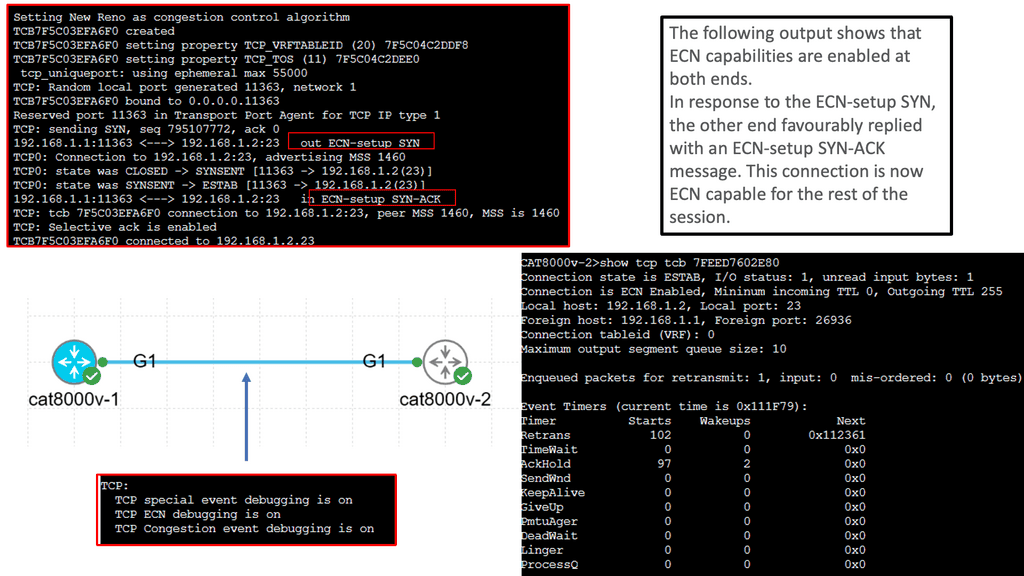
– To ensure that resources are available only to authorized users, firewalls protect the bandwidth or throughput of a private network. A firewall prevents worthless or malicious traffic from entering your network. A dam protects a river from flooding and overflowing, similar to how a dam works on a river. The dam prevents flooding and damage.

– In short, firewalls are network functions specifically tailored to inspect network traffic. Upon inspection, the firewall decides to carry out specific actions, such as forwarding or blocking it, according to some criteria. Thus, we can see firewalls as security network entities with several different types.

– The different firewall types will be used in other network locations in your infrastructure, such as distributed firewalls at a hypervisor layer. You may have a stateful firewall close to workloads while a packet-filtering firewall is at the network’s edge. As identity is now the new perimeter, many opt for a stateful inspection firewall nearer to the workloads. With virtualization, you can have a stateful firewall per workload, commonly known as virtual firewalls

Example Firewalling Technology: Linux Firewalling

Understanding UFW

UFW, a front-end for IPtables, is a user-friendly and powerful firewall tool designed for Linux systems. It provides a straightforward command-line interface, making it accessible even to those with limited technical knowledge. UFW enables users to manage incoming and outgoing traffic, creating an additional layer of defense against potential threats.

UFW offers a range of features that enhance system security. Firstly, it allows you to create rules based on IP addresses, ports, and protocols, granting you granular control over network traffic. Additionally, UFW supports IPv4 and IPv6, ensuring compatibility with modern network configurations. Furthermore, UFW seamlessly integrates with other firewall solutions and can be easily enabled or disabled per your needs.

Example Firewall Technology: CBAC Firewall

Cisco CBAC firewall goes beyond traditional stateless firewalls by inspecting and filtering traffic based on contextual information. It operates at the application layer of the OSI model and provides advanced security capabilities.

CBAC firewall offers a range of essential features that contribute to its effectiveness. These include intelligent packet inspection, stateful packet filtering, protocol-specific application inspection, and granular access control policies.

One of the primary objectives of CBAC firewalls is to enhance network security. By actively analyzing traffic flow context, they can detect and prevent various threats, such as Denial-of-Service (DoS) attacks, port scanning, and protocol anomalies.

CBAC Firewall

Stateful Firewall

A stateful firewall is a form of firewall technology that monitors incoming and outgoing network traffic and keeps track of the state of each connection passing through it. It acts as a filter, allowing or denying traffic based on configuration. Stateful firewalls are commonly used to protect private networks from potential malicious activity.

The primary function of a Stateful Inspection Firewall is to inspect the headers and contents of packets passing through it. It maintains a state table that keeps track of the connection state of each packet, allowing it to identify and evaluate the legitimacy of incoming and outgoing traffic. This stateful approach enables the firewall to differentiate between legitimate packets from established connections and potentially malicious packets.

Unlike traditional packet filtering firewalls, which only examine individual packets based on predefined rules, Stateful Inspection Firewalls analyze the entire communication session. This means that they can inspect packets in the context of the whole session, allowing them to detect and prevent various types of attacks, including TCP/IP-based attacks, port scanning, and unauthorized access attempts.

data center firewall
Diagram: The data center firewall.

**What is state and context?**

A process or application’s current state refers to its most recent or immediate state. It is possible to compare the connection a user tries to establish with the list of connections stored in a firewall. A tracking device determines which states are safe and which pose a threat.

Analyzing IP addresses, packets, or other kinds of data can identify repeating patterns. In the context of a connection, for instance, it is possible to examine the contents of data packets that enter the network through a stateful firewall. Stateful firewalls can block future packets containing unsafe data.

Stateful Inspection:

A: Stateful packet inspection determines which packets are allowed through a firewall. This method examines data packets and compares them to packets that have already passed through the firewall.

B: Stateful packet filtering ensures that all connections on a network are legitimate. Static packet filtering on the network also examines network connections, but only as they arrive, focusing on packet header data. The firewall can only see where the data comes from and where it is going with this data.

C: Generally, we interact directly with the application layer and have networking and security devices working at the lower layers. So when host A wants to talk to host b, it will go through several communication layers with devices working at each layer. A device that works at one of these layers is a stateful firewall that can perform the stateful inspection.

**Deep Packet Inspection (DPI)**

Another significant advantage of Stateful Inspection Firewalls is their ability to perform deep packet inspection. This means that they can analyze the content of packets beyond their headers. By examining the payload of packets, Stateful Inspection Firewalls can detect and block potentially harmful content, such as malware, viruses, and suspicious file attachments. This advanced inspection capability adds an extra layer of security to the network.

Understanding Deep Packet Inspection:

Deep Packet Inspection, often abbreviated as DPI, is a sophisticated technology used to monitor and analyze network traffic at a granular level. Unlike traditional packet inspection, which only examines packet headers, DPI delves deep into the packet payload, allowing for in-depth analysis and classification of network traffic.

DPI plays a vital role in network management and security. By inspecting the contents of packets, it helps network administrators identify and control applications, protocols, and even specific users. This level of visibility allows for better bandwidth management, traffic shaping, and the implementation of security measures to protect against malicious activities and intrusions.

**Applications of DPI**

1. Network Security: DPI enables the detection of malicious activities such as intrusions, malware, and unauthorized access attempts. It helps in identifying and preventing data breaches by monitoring and analyzing network traffic patterns in real-time.

2. Quality of Service (QoS): DPI helps network administrators prioritize and allocate network resources based on specific applications or services. By understanding the nature of traffic passing through the network, DPI can optimize bandwidth allocation, ensuring a seamless and reliable user experience.

3. Regulatory Compliance: In certain industries, such as finance or healthcare, strict regulations govern data privacy and security. DPI assists organizations in meeting compliance requirements by monitoring and controlling network traffic.

Combining Security Features:

They can be combined with other security measures, such as antivirus software and intrusion detection systems. Stateful firewalls can be configured to be both restrictive and permissive and can be used to allow or deny certain types of traffic, such as web traffic, email traffic, or FTP traffic. They can also control access to web servers, databases, or mail servers. Additionally, stateful firewalls can detect and block malicious traffic, such as files, viruses, or port scans.

Transport Control Protocol (TCP):

TCP allows data to be sent and received simultaneously over the Internet. Besides assisting in transmitting information, TCP also contains data that can cause a connection to be reset (RST), resulting in its termination. TCP uses the FIN (finish) command when the transmission should end. When data packets reach their destination, they are grouped into understandable data. 

Stateful firewalls examine packets created by the TCP process to keep track of connections. To detect potential threats, a stateful inspection firewall uses the three stages of a TCP connection: synchronize (SYN), synchronize-acknowledge (SYN-ACK), and acknowledge (ACK). During the TCP handshake, stateful firewalls can discard data if they detect bad actors.

Three-way handshake:

During the three-way handshake, both sides synchronize to establish a connection and then acknowledge one another. Each side transmits information to the other as part of this process, which is inspected for errors. In a stateful firewall, the data sent during the handshake can be examined to determine the packet’s source, destination, sequence, and content. The firewall can reject data packets if it detects threats.

Firewall Inspection with Cloud Armor

**What is Google Cloud Armor?**

Google Cloud Armor is a cloud-based security service that provides robust protection for web applications hosted on Google Cloud Platform (GCP). It acts as a shield against distributed denial-of-service (DDoS) attacks, SQL injections, cross-site scripting (XSS), and other common threats. With its global reach and scale, Google Cloud Armor helps ensure your applications remain available and secure, even in the face of sophisticated attacks.

**Delving into Stateful Inspection**

Stateful inspection is a critical component of Google Cloud Armor’s security framework. Unlike traditional packet filtering, which inspects packets individually, stateful inspection monitors the entire state of active connections. This means that Google Cloud Armor can track and analyze the context of data packets as they flow through your network, providing a more comprehensive layer of security. By understanding the state and characteristics of each connection, stateful inspection helps effectively distinguish between legitimate traffic and potential threats.
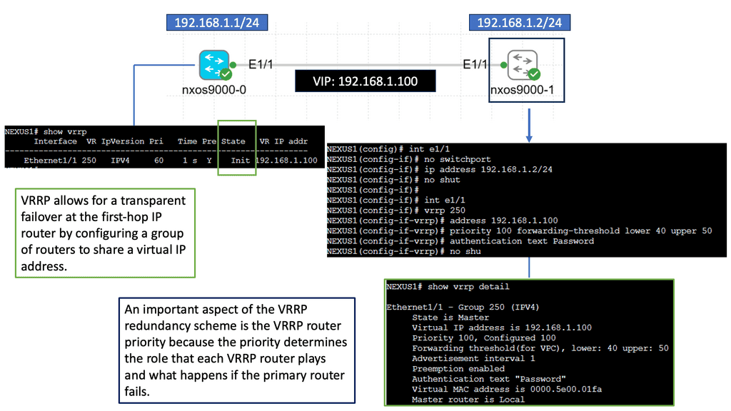
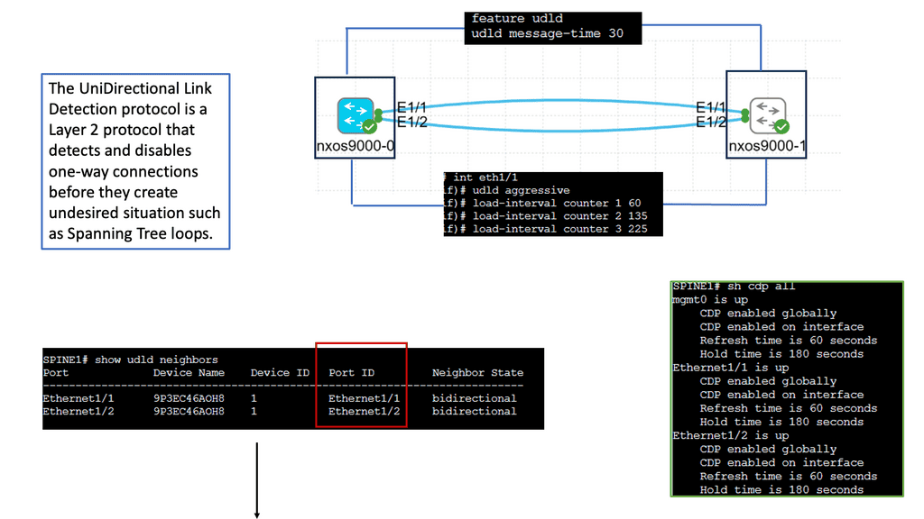
**The Benefits of Stateful Inspection**

The inclusion of stateful inspection within Google Cloud Armor offers several key benefits. First and foremost, it enhances threat detection and mitigation capabilities by allowing for a more granular analysis of network traffic. This means your applications are better protected against sophisticated attacks that might otherwise slip through less comprehensive security measures. Additionally, stateful inspection helps optimize performance by ensuring that only legitimate traffic is processed, reducing the risk of false positives and minimizing latency.

**Implementing Google Cloud Armor with Stateful Inspection**

Setting up Google Cloud Armor with stateful inspection is a straightforward process. First, ensure your applications are hosted on GCP, as this is a prerequisite for using Google Cloud Armor. Next, configure security policies that align with your specific needs and threat landscape. These policies will dictate how stateful inspection is applied, allowing you to tailor the level of scrutiny to your organization’s requirements. Finally, monitor and adjust your settings as necessary to ensure optimal protection and performance.

Google Cloud Compute Security 

Google Compute Security

Google Compute Engine allows businesses to leverage the cloud for scalable and flexible computing resources. However, with this convenience comes the need for stringent security measures. Cyberattacks and data breaches pose a significant risk, making it crucial to implement robust security protocols to safeguard your Google Compute resources.

FortiGate is a comprehensive network security platform that offers advanced threat protection, secure connectivity, and granular visibility into your network traffic. With its cutting-edge features, FortiGate acts as a shield, defending your Google Compute resources from malicious activities, unauthorized access, and potential vulnerabilities.

Advanced Threat Protection: FortiGate leverages industry-leading security technologies to identify and mitigate advanced threats, including malware, viruses, and zero-day attacks. Its robust security fabric provides real-time threat intelligence and proactive defense against evolving cyber threats.

Secure Connectivity: FortiGate ensures secure connectivity between your Google Compute resources and external networks. It offers secure VPN tunnels, encrypted communication channels, and robust access controls, enabling you to establish trusted connections while preventing unauthorized access.

Granular Visibility and Control: With FortiGate, you gain granular visibility into your network traffic, allowing you to monitor and control data flows within your Google Compute environment. Its intuitive dashboard provides comprehensive insights, enabling you to detect anomalies, identify potential vulnerabilities, and take proactive security measures.

The Benefits of Deep Packet Inspection with FortiGate

Enhanced Network Visibility: By leveraging DPI with FortiGate, organizations gain unparalleled visibility into their network traffic. Detailed insights into application usage, user behavior, and potential security vulnerabilities allow for proactive threat mitigation and network optimization.

Granular Application Control: DPI enables organizations to enforce granular application control policies. By identifying and classifying applications within network traffic, FortiGate allows administrators to define and enforce policies that govern application usage, ensuring optimal network performance and security.

Intrusion Detection and Prevention: With DPI, FortiGate can detect and prevent intrusions in real-time. By analyzing packet content and comparing it against known threat signatures and behavioral patterns, FortiGate can swiftly identify and neutralize potential security breaches, safeguarding sensitive data and network infrastructure.

Before you proceed, you may find the following helpful post for pre-information:

  1. Network Security Components
  2. Virtual Data Center Design
  3. Context Firewall
  4. Cisco Secure Firewall

Stateful Inspection Firewall

The term “Firewall.”

The term “firewall” comes from a building and automotive construction concept of a wall built to prevent the spread of fire from one area into another. This concept was then taken into the world of network security. The firewall’s assignment is to set all restrictions and boundaries described in the security policy on all network traffic that passes the firewall interfaces. Then, we have the concept of firewall filtering that compares each packet received to a set of rules that the firewall administration configures.

These exception rules are derived from the organization’s security policy. The firewall filtering rules state that the contents of the packet are either allowed or denied. Therefore, based on firewall traffic flow, the packet continues to its destination if it matches an allowed rule. If it matches a deny rule, the packet is dropped. The firewall is the barrier between a trusted and untrusted network, often used between your LAN and WAN. It’s typically placed in the forwarding path so that all packets have to be checked by the firewall, where we can drop or permit them.

Apply a multi-layer approach to security. 

When it comes to network security, organizations must adopt a multi-layered approach. While Stateful Inspection Firewalls provide essential protection, they should be used in conjunction with other security technologies, such as intrusion detection systems (IDS), intrusion prevention systems (IPS), and virtual private networks (VPNs). This combination of security measures ensures comprehensive protection against various cyber threats.

Stateful Inspection Firewalls are integral to network security infrastructure. By inspecting packets in the context of the entire communication session, these firewalls offer enhanced security and greater control over network traffic. By leveraging advanced inspection techniques, deep packet inspection, and a stateful approach, Stateful Inspection Firewalls provide a robust defense against evolving cyber threats. Organizations prioritizing network security should consider implementing Stateful Inspection Firewalls as part of their security strategy.

Guide on Cisco ASA firewall

In the following lab guide, you can see we have an ASA working in routed mode. In routed mode, the ASA is considered a router hop in the network. Each interface that you want to route between is on a different subnet. You can share Layer 3 interfaces between contexts.

Traditionally, a firewall is a routed hop and acts as a default gateway for hosts that connect to one of its screened subnets. On the other hand, a transparent firewall is a Layer 2 firewall that acts like a “bump in the wire” or a “stealth firewall” and is not seen as a router hop to connected devices. However, like any other firewall, access control between interfaces is controlled, and the usual firewall checks are in place.

The Adaptive Security Algorithm considers the state of a packet when deciding to permit or deny the traffic. One enforced parameter for the flow is that traffic enters and exits the same interface. The ASA drops any traffic for an existing flow that enters a different interface. Traffic zones let you group multiple interfaces so that traffic entering or exiting any interface in the zone fulfills the Adaptive Security Algorithm security checks.

The command:  show asp table routing displays the accelerated security path tables for debugging purposes and the zone associated with each route. See the following output for the show asp table routing command:

Cisco ASA configuration
Diagram: Cisco ASA Configuration

**Firewall filtering rules**

Firewall filtering rules help secure a network from unauthorized access and malicious activity. These rules protect the network by controlling traffic flow in and out of the network. Firewall filtering rules can allow or deny traffic based on source and destination IP addresses, ports, and protocols.

Firewall filtering rules should be tailored to the specific needs of a given network. Generally, it is recommended to implement a “deny all” rule and then add rules to allow only the necessary traffic. This helps block any malicious activity while allowing legitimate traffic. When creating firewall filtering rules, it is essential to consider the following:

  • Make sure to use the most up-to-date protocols and ports.
  • Be aware of any potential risks associated with the traffic being allowed.
  • Use logging to monitor traffic and ensure that expected behavior is occurring.
  • Ensure that the rules are implemented consistently across all firewalls.
  • Ensure that the rules are regularly reviewed and updated as needed.

Guide on default firewall inspection

The Cisco ASA Firewall uses so-called “security levels” that indicate how trusted an interface is compared to another. The higher the security level, the more trusted the interface is. Each interface on the ASA is a security zone, so using these security levels gives us different trust levels for our security zones. Therefore, we have the default firewall inspection. We will discuss this more later.

Below, we have three routers and subnets with 1 ASA firewall.

  • Interface G0/0 as the INSIDE.
  • Interface G0/1 as the OUTSIDE.
  • Interface G0/2 as our DMZ.

The name command is used to specify a name for the interface. As you can see, the ASA recognizes INSIDE, OUTSIDE, and DMZ names. And sets the security level for that interface to a default level. Therefore, restriction of traffic flow.

Remember that the ASA can reach any device in each security zone. This doesn’t work since we are trying to go from a security level of 0 (outside) to 100 (inside) or 50 (DMZ). We will have to use an access list if you want to allow this traffic.

Firewall inspection
Diagram: Default Firewall Inspection.

What Is a Stateful Firewall?

The stateful firewall examines Layer 4 headers and above, analyzing firewall traffic flow and enabling support for Application-aware inspections. Stateful inspection keeps track of every connection passing through their interfaces by analyzing packet headers and additional payload information.

Stateful Firewall
Diagram: Stateful firewall. Source Cisco.

Stateful Firewall Operation

You can see how filtering occurs at layers 3 and 4 and that the packets are examined as a part of the TCP session.

The topmost part of the diagram shows the three-way handshake, which takes place before the commencement of the session and is explained as follows.

  1. Syn refers to the initial synchronization packet sent from one host to another; in this case, the client to the server.
  2. The server sends an acknowledgment of the syn, and this is known as syn-ack
  3. The client again acknowledges this syn-ack, completing the process and initiating the TCP session.
  4. Both parties can end the connection anytime by sending a FIN to the other side. This is similar to a telephone call where the caller or the receiver could hang up.

State and Context.

The two important terms to understand are state and context information. Filtering is based on the state and context information the firewall derives from a session’s packets. The firewall will store state information in its state table, which is updated regularly. For example, in TCP, this state is reflected in specific flags such as SYN, ACK, and FIN. Then, we have the context. This includes source and destination port, IP address, and sequence numbers of any metadata. The firewall also stores this information and updates regularly based on traffic flowing through the firewall.

Firewall state table

A firewall state table is a data structure that stores information about a network firewall’s connection state. It determines which packets are allowed to pass through the firewall and which are blocked. The table contains entries for each connection, including source and destination IP addresses, port numbers, and other related information.

The firewall state table is typically organized into columns, with each row representing an individual connection. Each row contains the source and destination IP address, the port numbers, and other related information.

For example, the source IP address and port number indicate the origin of the connection, while the destination IP address and port number indicate the destination of the connection. Additionally, the connection’s state is stored in the table, such as whether the connection is established, closed, or in transit.

The state table also includes other fields that help the firewall understand how to handle the connection, such as the connection duration, the type of connection being established, and the protocol used.

Stateful inspection firewall
Diagram: Stateful inspection firewall. Source: Science Direct.

So whenever a packet arrives at a firewall to seek permission to pass through it, the firewall checks from its state table if there is an active connection between the two points of source and destination of that packet. The endpoints are identified by something known as sockets. A socket is similar to an electrical socket at your home, which you use to plug your appliances into the wall.

Similarly, a network socket consists of a unique IP address and a port number and is used to plug one network device into the other. The packet flags are matched against the state of the connection to which it belongs, which is allowed or denied based on that. For example, if a connection already exists and the packet is a Syn packet, it must be rejected since Syn is only required initially.

CBAC Firewalling on Cisco IOS

Understanding CBAC Firewall

CBAC firewall, also known as stateful firewall, is a robust security mechanism developed by Cisco Systems. Unlike traditional packet-filtering firewalls, the CBAC firewall adds layer of intelligence by examining the context of network connections. It analyzes individual packets and the entire session, providing enhanced security against advanced threats.

CBAC firewall offers a range of powerful features, making it a preferred choice for network administrators. First, it provides application-layer gateway functionality, which allows it to inspect and control traffic at the application layer. Second, the CBAC firewall can dynamically create temporary access rules based on a connection’s state. This adaptability ensures that only valid and authorized traffic is allowed through the firewall.

Compared to simple access lists, CBAC (Context-Based Access Control) offers some more features. CBAC can inspect up to layer 7 of the OSI model, and dynamic rules can be created to allow return traffic. Reflexive access lists are similar to this, but the reflexive ACL inspects only layers up to 4.

CBAC will be demonstrated in this lab, and you’ll see why this firewall feature is helpful. For this, I will use three routers: In the example above, we have three routers. Please assume that the router on the left (R1) is a device on the Internet, while the host on the right (R3) is a device on our local area network (LAN). We will configure CBAC on R2, the router that protects us from Internet traffic.

CBAC Firewall

These pings are failing, as you can see on the console. The inbound ACL drops these packets on R2. To solve this problem, we must add a permit statement to the access list so the ping makes it through. That’s not a scalable solution since we don’t know what kind of traffic we have on our LAN, and we don’t want a big access list with hundreds of permit statements. What we are going to do is configure CBAC so it will inspect the traffic and automatically allow the return traffic through

CBAC Firewall


Stateful Firewall and Interface Configuration

It would be best to consider the interfaces in firewall terms when considering a stateful inspection firewall. For example, some interfaces are connected to protected networks, where data or services must be secured. Others connect to public or unprotected networks, where untrusted users and resources are located.

The top portion of the diagram below shows a stateful firewall with only two interfaces connecting to the inside (more secure) and outside (less secure) networks. The bottom portion shows the stateful inspection firewall with three interfaces connecting to the inside (most secure), DMZ (less secure), and outside (least secure) networks. The firewall has no concept of these interface designations or security levels; these concepts are put into play by the inspection processes and policies configured.

So you need to explain to the firewall which interface is at what security level. And this will effect the firewall traffic flow. Some traffic will be denied by default between specific interfaces with default security levels.

stateful inspection firewall

Interface configuration specific to ASA

Since version 7.0 of the ASA code, configuring interfaces in the firewall appliance is very similar to configuring interfaces in IOS-based platforms. If the firewall connection to the switch is an 802.1q trunk (the ASA supports 802.1q only, not ISL), you can create sub-interfaces corresponding to the VLANs carried over the trunk. Do not forget to assign a VLAN number to the sub-interface. The native (untagged) VLAN of the trunk connection maps to the physical interface and cannot be assigned to a sub-interface.

Full state of active network connections

So, we know that the stateful firewall monitors the entire state of active network connections and constantly analyses the complete context of traffic and data packets. Then, we have the payload to consider. The payload is part of transmitted data, the intended message, headers, and metadata sent only to enable payload delivery.

Payloads offer transaction information, which can protect against some of the most advanced network attacks. For example, deep packet inspection configures the stateful firewall to deny specific Hypertext Transfer Protocol ( HTTP ) content types or specific File Transfer Protocol ( FTP ) commands, which may be used to penetrate networks. 

Stateful inspection and Deep Packet Inspection (DPI)

The following diagram shows the OSI layers involved in the stateful inspection. As you can see, Stateful inspection operates primarily at the transport and network layers of the Open Systems Interconnection (OSI) model for how applications communicate over a network. However, it can also examine application layer traffic, if only to a limited degree. Deep Packet Inspection (DPI) is higher up in the OSI layers.

DPI is considered to be more advanced than stateful packet filtering. It is a form of packet filtering that locates, identifies, classifies, and reroutes or blocks packets with specific data or code payloads that conventional packet filtering, which examines only packet headers, cannot detect. Many firewall vendors will have the stateful inspection and DPI on the same appliance. However, a required design may require a separate appliance for compliance or performance reasons.

Stateful Inspection Firewall
Diagram: Stateful inspection firewall.

Stateful Inspection Firewall

What is a stateful firewall?

A stateful firewall tracks and monitors the state of active network connections while analyzing incoming traffic and looking for potential traffic and data risks. The state is a process or application’s most recent or immediate status. In a firewall, the state of connections is stored, providing a list of connections against which to compare the connection a user is attempting to make.

Stateful packet inspection is a technology that stateful firewalls use to determine which packets are allowed through the firewall. It works by examining the contents of a data packet and then comparing them against data about packets that have previously passed through the firewall.

Stateful Firewall Feature

Stateful Firewall 

Better logging than standard packet filters

Protocols with dynamic ports


TCP SYN cookies


TCP session validation


No TCP fingerprinting

Not present

Stateful firewall and packet filters

The stateful firewall contrasts packet filters that match individual packets based on their source/destination network addresses and transport-layer port numbers. Packet filters have no state or check the validity of transport layer sessions such as sequence numbers, Transmission Control Protocol ( TCP ) control flags, TCP acknowledgment, or fragmented packets. The critical advantage of packet filters is that they are fast and processed in hardware.

Reflexive access lists are closer to a stateful tool than packet filters. Whenever a TCP or User Datagram Protocol ( UDP ) session permits, matching return traffic is automatically added. The disadvantage of reflexive access lists is they cannot detect/drop malicious fragments or overlapping TCP segments. Transport layer session inspection goes beyond reflexive access lists and addresses fragment reassembly and transport-layer validation.

Application-level gateways ( ALG ) add additional awareness. They can deal with FTP or Session Initiation Protocol ( SIP ) applications that exchange IP addresses and port numbers in the application payload. These protocols operate by opening additional data sessions and multiple ports.

Packet filtering
Diagram: Packet filtering. Source Research Gate.

**Simple packet filters for a perfect world*8

In a perfect world where most traffic exits the data center, servers are managed with regular patching, servers listen on standard TCP or UDP ports, and designers could get away with simple packet filters. However, in the real world, each server is a distinct client, has multiple traffic flows to and from the data center and back-end systems, and unpredictable source TCP or UDP port number makes using packet filters impractical.

Instead, additional control should be implemented with deep packet inspection for unpredictable scenarios and poorly managed servers. Stateful firewalls keep state connections and allow traffic to return dynamically. Return traffic is permitted if the state of that flow is already in the connection table. The traffic needs to be part of a return flow. If not, it’s dropped.

**A stateless firewall – predefined rule sets**

A stateless firewall uses a predefined set of rules. If the arriving data packet conforms to the rules, it is considered “safe.” The data packet is allowed to pass through. With this approach to firewalling, traffic is classified instead of inspected. The process is less rigorous compared to what a stateful firewall does.

Remember that a stateless firewall does not differentiate between certain kinds of traffic, such as Secure Shell (SSH) versus File Transfer Protocol (FTP). A stateless firewall may classify these as “safe” and allow them to pass through, which can result in potential vulnerabilities.

A stateful firewall holds context across all its current sessions rather than treating each packet as an isolated entity, as with a stateless firewall. With stateless inspection, lookup functions impact the processor and memory resources much less, resulting in faster performance even if traffic is heavy.

**The Stateful Firewall and Security Levels**

Regardless of the type of firewall mode or single or multiple contexts, the Adaptive Security Appliance ( ASA ) permits traffic based on a concept of security levels configured per interface. This is a crucial point to note for ASA failover and how you design your failover firewall strategy. The configurable range is from level 0 to 100. Every interface on ASA must have a security level.

The security level allows configured interface trust-ability and can range from 0, which is the lowest, to 100, which is the highest—offering ways to control traffic flow based on security level numbering. The default security level is “0”, configuring the name on the interface “inside” without explicitly entering a security level; then, the ASA automatically sets the security level to 100 ( highest ).

By default, based on the configured nameif, ASA assigns the following implicit security levels to interfaces:

  • 100 to a nameif of inside.
  • 0 to a nameif of outside.
  • 0 to all other nameifs.

Without any configured access lists, ASA implicitly allows or restricts traffic flows based on the security levels:

Securty Levels and Traffic Flows

  • Traffic from high-security level to low-security level is allowed by default (for example, from 100 to 0, or in our case, from 60 to 10)

  • Traffic from low-security level to the high-security level is denied by default; to allow traffic in this direction, an ACL must be configured and applied (at the interface level or global level)

  • Traffic between interfaces with an identical security level is denied by default (for example, from 20 to 20, or in our case, from 0 to 0); to allow traffic in this direction, the command same-security-traffic permit inter-interface must be configured

Firewall traffic flow between security levels

By default, traffic can flow from highest to lowest without explicit configuration. Also, interfaces on the same security level cannot directly communicate, and packets cannot enter and exit the same interface. Override the defaults, permit traffic by allowing high to low; explicitly configure ACLs on the interface or newer version use-global ACL. Global ACL affects all interfaces in all directions.

Firewall traffic flow

Firewall traffic flows

Inter-interface communication ( Routed Mode only ): Enter the command “same-security-traffic permit inter-interface” or permit traffic explicitly with an ACL. This will give design granularity and allow the configuration of more communicating interfaces. Intra-interface communication: This is configured for traffic hair-pining (traffic leaves on the outside interface and goes back out the outside interface ).

This is useful for Hub and Spoke VPN deployments; traffic enters an interface and routes back out the same interface—Spoke-to-Spoke communication. To enable Intra-Interface communication, enter the command “same-security-traffic permit intra-interface.”

Default inspection and Modular Policy Framework ( MPF )

ASA implements what is known as the Modular Policy Framework ( MPF ). MPF controls WHAT traffic is inspected, such as Layer 3 or Layer 4 inspection of TCP, UDP, ICMP, an application-aware inspection of HTTP, or DNS. It also controls HOW traffic is inspected based on connection limits and QoS parameters.

ASA inspects TCP / UDP from the inside (higher-security level ) to the outside ( lower-security level ). This cannot be disabled. No traffic inspection from outside to inside unless it is from an original flow.

An entry is created in the state table, so when flows return, it checks the state table before it goes to implicit deny ACL. The state is created during traffic leaves, so it checks the specific connection and application data when the return flows come back. It does more than Layer 3 or 4 inspections and depends on the application.

It does not, by default, inspect ICMP traffic. Enable ICMP inspection with a global inspection policy or explicitly allow with an interface or Global ACLs. ASA global policy affects all interfaces in all directions. The state table is checked before any ACL. A good troubleshooting tool, Packet Tracer, goes through all inspections and displays the order the ASA is processing.

modular policy framework
Diagram: Modular Policy Framework


Key Stateful Inspection Firewall Summary Points:

Main Checklist Points To Consider

  • Firewalls carry out specific actions based on policy. The default policy can exist. Different firewall types exist for different parts of the network.

  • The stateful firewall monitors the full state of the connections. The state is held in a state table.

  • Standard packet filters don’t state or check the valid nature of the transport layer sessions. They do not do a stateful inspection.

  • Firewalls will have default rules based on interface configurations. Default firewall traffic flow is based on an interface security level.

  • The Cisco ASA operates with a Modular Policy Framework (MPF) technology. ASA is a popular stateful firewall.

Firewalls and secure web gateways (SWGs) play similar and overlapping roles in securing your network. Both analyze incoming information and seek to identify threats before they enter your system. Despite sharing a similar function, they have some key differences, such as the “classical” distinction between secure web gateways and firewalls.

The basic distinctions:

  • Firewalls inspect data packets
  • Secure web gateways inspect applications
  • Secure web gateways set and enforce rules for users

Guide on traffic flows and NAT

I have the Cisco ASA configured with Dynamic NAT in the following guide. This is the same setup as before. In the middle, we have our ASA; its G0/0 interface belongs to the inside, and the G0/1 interface belongs to the outside.  I have not configured anything on the DMZ interfaces.

You need to configure object groups for this ASA version. I have configured a network object that defines the pool with public IP addresses we want to use for translation. The IP address that has been translated is marked in the red box below.

The show nat command shows us that some traffic has been translated from the inside to the outside.

The show xlate command shows that the IP address 192.168.1.1 has been translated to 192.168.2.196. It also tells us what kind of NAT we are doing here (dynamic NAT in our example) and how long this entry has been idle.

Firewall traffic flow
Diagram: Firewall traffic flow and NAT

Summary: Stateful Inspection Firewall

In today’s interconnected world, where cyber threats are becoming increasingly sophisticated, ensuring the security of our networks is paramount. One effective tool in the arsenal of network security is the stateful inspection firewall. In this blog post, we delved into the inner workings of stateful inspection firewalls, exploring their features, benefits, and why they are essential in safeguarding your network.

Understanding Stateful Inspection Firewalls

Stateful inspection firewalls go beyond traditional packet filtering by actively monitoring the state of network connections. They keep track of the context and content of packets, making intelligent decisions based on the connection’s state. By examining the entire packet, including the source and destination addresses, ports, and sequence numbers, stateful inspection firewalls provide a higher security level than simple packet filtering.

Key Features and Functionality

Stateful inspection firewalls offer a range of essential features that enhance network security. These include:

1. Packet Filtering: Stateful inspection firewalls analyze packets based on predetermined rules, allowing or blocking traffic based on factors like source and destination IP addresses, ports, and protocol type.

2. Stateful Tracking: Maintaining connection state information allows stateful inspection firewalls to track ongoing network sessions. This ensures that only legitimate traffic is allowed, preventing unauthorized access.

3. Application Layer Inspection: Stateful inspection firewalls can inspect and analyze application-layer protocols, providing additional protection against attacks that exploit vulnerabilities in specific applications.

Benefits of Stateful Inspection Firewalls

Implementing a stateful inspection firewall offers several advantages for network security:

1. Enhanced Security: By actively monitoring network connections and analyzing packet contents, stateful inspection firewalls provide stronger protection against various types of cyber threats, such as network intrusions and denial-of-service attacks.

2. Improved Performance: Stateful inspection firewalls optimize network traffic by efficiently managing connection states and reducing unnecessary packet processing. This leads to smoother network performance and better resource utilization.

3. Flexibility and Scalability: Stateful inspection firewalls can be customized to meet specific security requirements, allowing administrators to define rules and policies based on their network’s unique characteristics. Additionally, they can handle high traffic volumes without sacrificing performance.

Considerations for Implementation

While stateful inspection firewalls offer robust security, it’s important to consider a few factors during implementation:

1. Rule Configuration: Appropriate firewall rules are crucial for effective protection. To ensure that the firewall is correctly configured, a thorough understanding of the network environment and potential threats is required.

2. Regular Updates: Like any security solution, stateful inspection firewalls require regular updates to stay effective. Ensuring up-to-date firmware and rule sets are essential for addressing emerging threats.

Conclusion:

Stateful inspection firewalls are a critical defense against cyber threats, providing comprehensive network protection through their advanced features and intelligent packet analysis. Implementing a stateful inspection firewall can fortify your network’s security, mitigating risks and safeguarding sensitive data. Stay one step ahead in the ever-evolving landscape of cybersecurity with the power of stateful inspection firewalls.

fabricpath design

Data Center Fabric

Data Center Fabric

In today's digital age, where vast amounts of data are generated and processed, data centers play a vital role in ensuring seamless and efficient operations. At the heart of these data centers lies the concept of data center fabric – a sophisticated infrastructure that forms the backbone of modern computing. In this blog post, we will delve into the intricacies of data center fabric, exploring its importance, components, and benefits.

Data center fabric refers to the underlying architecture and interconnectivity of networking resources within a data center. It is designed to efficiently handle data traffic between various components, such as servers, storage devices, and switches while ensuring high performance, scalability, and reliability. Think of it as the circulatory system of a data center, facilitating the flow of data and enabling seamless communication between different entities.

A well-designed data center fabric consists of several key components. Firstly, network switches play a vital role in facilitating connectivity among different devices. These switches are often equipped with advanced features such as high port density, low latency, and support for various protocols. Secondly, the physical cabling infrastructure, including fiber optic cables, ensures fast and reliable data transfer. Lastly, network management tools and software provide centralized control and monitoring capabilities, optimizing the overall performance and security of the fabric.

Data center fabric offers numerous benefits that contribute to the efficiency and effectiveness of data center operations. Firstly, it enables seamless scalability, allowing organizations to easily expand their infrastructure as their needs grow. Additionally, data center fabric enhances network resiliency by providing redundant paths and minimizing single points of failure. This ensures high availability and minimizes the risk of downtime. Moreover, the centralized management of the fabric simplifies network administration and troubleshooting, saving valuable time and resources.

As the demand for digital services continues to skyrocket, data center fabric plays a pivotal role in shaping the digital landscape. Its high-speed and reliable connectivity enable the smooth functioning of cloud computing, e-commerce platforms, content delivery networks, and other services that rely on data centers. Furthermore, data center fabric empowers enterprises to adopt emerging technologies such as artificial intelligence, big data analytics, and Internet of Things (IoT), which heavily depend on robust network infrastructure.

Highlights: Data Center Fabric

Understanding Data Center Fabric

– Data center fabric refers to the underlying network infrastructure that interconnects various elements within a data center. It encompasses a combination of switches, routers, and other networking devices that enable high-speed, reliable, and scalable communication between servers, storage systems, and other components.

– Data center fabric is built upon a robust and scalable architecture that ensures efficient data flow and minimizes bottlenecks. Traditionally, this architecture relied on a three-tier model consisting of core, aggregation, and access layers. However, with the advent of modern technologies, a flatter two-tier model and even fabric-based architectures have gained prominence, offering increased flexibility, reduced latency, and simplified management.

– Implementing a well-designed data center fabric brings forth a multitude of benefits. Firstly, it enhances network performance by providing high bandwidth and low latency, facilitating rapid data transfer and real-time applications. Secondly, data center fabric enables seamless scalability, allowing organizations to effortlessly expand their infrastructure as their needs grow. Moreover, it improves resiliency by offering redundant paths and reducing the risk of single points of failure.

– Designing an efficient and reliable data center fabric requires careful planning and consideration. Factors such as network topology, traffic patterns, bandwidth requirements, and security must be thoroughly evaluated. Additionally, selecting the appropriate switching technologies, such as Ethernet or Fibre Channel, and implementing effective traffic management mechanisms are essential to ensure optimal performance and resource utilization.

**The role of a data center fabric**

In a data center, network devices are typically deployed in two (or sometimes three) highly interconnected layers or fabrics. Unlike traditional multitier architectures, data center fabrics flatten the network architecture, reducing distances between endpoints. This design results in very low latency and very high efficiency.

All data center fabrics share another design goal. In addition to providing a solid layer of connectivity, they transport the complexity of virtualization, segmentation, stretched Ethernet segments, workload mobility, and other services to an overlay that rides on top of the fabric. Underlays are fabrics used in conjunction with overlays.

**Advent of Network Virtualisation**

Due to the advent of network virtualization, applications have also evolved from traditional client/server architecture to highly distributed microservices architectures composed of cloud-native workloads. A scale-out approach connects all components to different access switches instead of having all components on the same physical server

Data center fabric refers to the interconnected network of switches, routers, and other networking devices that form the backbone of a data center. It serves as the highway for data traffic, allowing efficient communication between various components within the data center infrastructure.  

1. Network Switches: Network switches form the core of the data center fabric, providing connectivity between servers, storage devices, and other networking equipment. These switches are designed to handle massive data traffic, offering high bandwidth and low latency to ensure optimal performance.

2. Cabling Infrastructure: A well-designed cabling infrastructure is crucial for data center fabric. High-speed fiber optic cables are commonly used to connect various components within the data center, ensuring rapid data transmission and minimizing signal loss.

3. Network Virtualization: Network virtualization technologies, such as software-defined networking (SDN), play a significant role in the data center fabric. By decoupling the network control plane from the physical infrastructure, SDN enables centralized management, improved agility, and flexibility in allocating resources within the data center fabric.

4. Redundancy and High Availability: Data center fabric incorporates redundancy mechanisms to ensure high availability. By implementing redundant switches and links, it provides failover capabilities, minimizing the risk of downtime and maximizing system reliability.

5. Scalability: One of the defining features of data center fabric is its ability to scale horizontally. With the ever-increasing demand for computational power, data center fabric allows for the seamless addition of new devices and resources, ensuring the data center can keep up with growing requirements.

Data Center Fabric with VPC

Data center fabric serves as the foundational layer for cloud providers like Google Cloud, facilitating high-speed data transfer and scalability. It allows for the integration of various network components, creating a unified infrastructure that supports the demands of cloud services. By leveraging a robust fabric, Google Cloud VPC can offer customers a resilient and flexible environment, ensuring that resources are efficiently allocated and managed across diverse workloads.

**Understanding the Basics of VPC**

A Virtual Private Cloud (VPC) is essentially a private network within a public cloud. It allows users to create and manage their own isolated network segments within Google Cloud. With VPC, you can define your own IP address range, create subnets, and configure firewalls and routes. This level of control ensures that your resources are both secure and efficiently organized. Google Cloud’s VPC offers global reach and a high degree of flexibility, making it a preferred choice for many enterprises.

**Key Features and Benefits**

One of the standout features of Google Cloud’s VPC is its global reach, allowing for seamless communication across different regions. This global VPC capability means you can connect resources across the globe without the need for complex VPN setups. Additionally, VPC’s dynamic scalability ensures that your network can grow alongside your business needs. With features like private Google access, you can communicate securely with Google services without exposing your data to the public internet.

**Setting Up a VPC on Google Cloud**

Setting up a VPC on Google Cloud is straightforward, thanks to the intuitive interface and comprehensive documentation provided by Google. Start by defining your network’s IP address range and creating subnets in your desired regions. Configure firewall rules to control traffic in and out of your network, ensuring only authorized access. Google Cloud also provides tools like Cloud VPN and Cloud Interconnect to integrate your VPC with on-premises infrastructure, offering a hybrid cloud solution.

Example: IP Fabric with Clos

Clos fabrics provide physical connectivity between switches, facilitating the network’s goal of connecting workloads and servers in the fabric (and the outside world). Routing protocols are used to connect these endpoints. According to RFC 7938, BGP is the preferred routing protocol, with spines and leaves peering externally at each other (eBGP). A VXLAN-based fabric is built upon such a fabric, which is called an IP fabric.

Data centers typically use Clos fabrics or two-tier spine-and-leaf architectures. In this fabric, data passes through three devices before reaching its destination. Through a leaf device, east-west data center traffic travels upstream from one server to another and downstream to the destination server. The fundamental nature of fabric design is changed due to the absence of a network core.

  • With a spine-and-leaf fabric, intelligence is moved to the edges rather than centralized (for example, to implement policies). Endpoint devices (such as top-of-rack switches) or leaf devices (such as top-of-rack switches) can implement it. As a transit layer, the spine devices serve as leaf devices.
  • Spine-and-leaf fabrics allow east-west traffic flows to be accommodated more quickly than traditional hierarchical networks.
  • In east-west or north-south traffic, spine-and-leaf fabrics become equal. The exact number of devices processes it. This practice can significantly simplify the process of building fabrics with strict delay and jitter requirements.

 Google Cloud – Network Connectivity Center

**What is Google Network Connectivity Center?**

Google Network Connectivity Center is a centralized hub for managing network connectivity across various environments. Whether it’s on-premises data centers, virtual private clouds (VPCs), or other cloud services, NCC provides a unified platform to oversee and optimize network operations. By leveraging Google’s robust infrastructure, enterprises can ensure reliable and efficient connectivity, overcoming the complexities of traditional network management.

**Key Features of NCC**

1. **Centralized Management**: One of the standout features of NCC is its ability to provide a single pane of glass for network management. This centralized approach simplifies the oversight of complex network configurations, reducing the risk of misconfigurations and improving operational efficiency.

2. **Automated Routing**: NCC utilizes Google’s advanced algorithms to automate routing decisions, ensuring optimal data flow between different network endpoints. This automation not only enhances performance but also reduces the manual effort required to manage network routes.

3. **Integrated Security**: Security is a top priority for any network. NCC incorporates robust security features, including encryption and authentication, to protect data as it traverses different network segments. This integrated security framework helps safeguard sensitive information and ensures compliance with industry standards.

**Benefits for NCC Data Centers**

1. **Enhanced Connectivity**: With NCC, data centers can achieve seamless connectivity across diverse environments. This enhanced connectivity translates to improved application performance and a better user experience, as data can be accessed and transferred without significant delays or interruptions.

2. **Scalability**: As businesses grow, their network requirements evolve. NCC offers the scalability needed to accommodate this growth, allowing enterprises to expand their network infrastructure without compromising performance or reliability.

3. **Cost Efficiency**: By streamlining network management and reducing the need for manual intervention, NCC can lead to significant cost savings. Enterprises can allocate resources more effectively and focus on strategic initiatives rather than routine network maintenance.

**Impact on Hybrid and Multi-Cloud Environments**

Hybrid and multi-cloud environments are becoming increasingly common as organizations seek to leverage the best of both worlds. NCC plays a crucial role in these environments by providing a cohesive network management solution. It bridges the gap between different cloud services and on-premises infrastructure, enabling a more integrated and efficient network architecture.

Behind the Scenes of Google Cloud Data Centers

– Google Cloud data centers are marvels of engineering, built to handle massive amounts of data traffic and ensure the highest levels of performance and reliability. These facilities are spread across the globe, strategically located to provide efficient access to users worldwide. From the towering racks of servers to the intricate cooling systems, every aspect is meticulously designed to create an optimal computing environment.

– At the heart of Google Cloud data centers lies the concept of data center fabric. This refers to the underlying network infrastructure that interconnects all the components within a data center, enabling seamless communication and data transfer. Data center fabric is a crucial element in ensuring high-speed, low-latency connectivity between servers, storage systems, and other critical components.

A. Reliable Infrastructure: Google Cloud data centers leverage the power of data center fabric to ensure a reliable and robust infrastructure. By implementing a highly redundant fabric architecture, Google Cloud can provide a stable and resilient environment for hosting critical applications and services.

B. Global Interconnectivity: Google Cloud’s data center fabric extends across multiple regions, enabling seamless interconnectivity between data centers worldwide. This global network backbone ensures efficient data transfer and low-latency communication, allowing businesses to operate on a global scale..

Google Cloud Network Tiers

Understanding Network Tiers

Network tiers in Google Cloud refer to the different service levels offered for egress traffic from your virtual machines (VMs) to the internet. Google Cloud provides two primary network tiers: Premium Tier and Standard Tier. Each tier offers distinct features and cost structures, allowing you to tailor your network setup to your specific requirements.

The Premium Tier is designed for businesses that prioritize top-notch performance and global connectivity. It leverages Google’s vast private network infrastructure, ensuring low-latency and high-bandwidth connections between your VMs and the internet. With its global reach, the Premium Tier enables efficient data transfer across regions, making it an ideal choice for latency-sensitive applications and global workloads.

If cost optimization is a critical factor for your business, the Standard Tier provides a compelling solution. While it may not offer the same performance capabilities as the Premium Tier, the Standard Tier delivers cost-effective egress traffic pricing, making it suitable for applications with less stringent latency requirements. The Standard Tier still ensures reliable connectivity and offers a robust network backbone to support your workloads.


What is VPC Peering?

VPC peering is a connection between two Virtual Private Cloud networks that enables communication between them using private IP addresses. It allows resources within separate VPC networks to interact as if they were on the same network. Unlike traditional VPN connections or public internet connectivity, VPC peering ensures secure and direct communication between VPC networks.

a) Enhanced Connectivity: VPC peering simplifies establishing private connections between VPC networks, enabling seamless data transfer and communication.

b) Cost Efficiency: By leveraging VPC peering, businesses can reduce their reliance on costly external network connections or VPNs, leading to potential cost savings.

c) Low Latency: With VPC peering, data travels through Google’s private network infrastructure, resulting in minimal latency and faster response times.

d) Scalability and Flexibility: VPC peering allows you to connect multiple VPC networks within the same project or across different projects, ensuring scalability as your infrastructure grows.

**Data Center Fabric Performance**

1. Low Latency: Data center fabric minimizes the delay in data transmission, enabling real-time communication and faster application response times. This is crucial for latency-sensitive applications like financial trading or online gaming.

2. High Bandwidth: By utilizing technologies like high-speed Ethernet and InfiniBand, data center fabric can achieve impressive bandwidth capacities. This allows data centers to handle heavy workloads and support bandwidth-hungry applications such as big data analytics or video streaming.

3. Scalability: Data center fabric is designed to scale seamlessly, accommodating the ever-increasing demands of modern data centers. Its modular structure and distributed architecture enable easy expansion without compromising performance or introducing bottlenecks.

Optimizing Performance with Data Center Fabric

1. Traffic Optimization: The intelligent routing capabilities of data center fabric help optimize traffic flow, ensuring efficient data delivery and minimizing congestion. By intelligently distributing traffic across multiple paths, it balances the load and prevents bottlenecks.

2. Redundancy and Resilience: Data center fabric incorporates redundancy mechanisms to ensure high availability and fault tolerance. In the event of a link or node failure, it dynamically reroutes traffic to alternative paths, minimizing downtime and maintaining uninterrupted services.

Understanding TCP Performance Parameters

TCP performance parameters are crucial settings that determine how TCP behaves during data transmission. These parameters govern various aspects, such as congestion control, retransmission timeouts, and window sizes. Network administrators can optimize TCP performance based on specific requirements by fine-tuning these parameters.

Let’s explore some of the essential TCP performance parameters that can significantly impact network performance:

1. Congestion Window (CWND): The congestion window represents the number of unacknowledged packets a sender can transmit before expecting an acknowledgment. Properly adjusting CWND based on network conditions can prevent congestion and improve overall throughput.

2. Maximum Segment Size (MSS): MSS refers to the largest amount of data a TCP segment can carry. Optimizing the MSS value based on the network’s Maximum Transmission Unit (MTU) can enhance performance by reducing unnecessary fragmentation and reassembly.

3. Retransmission Timeout (RTO): RTO determines the time a sender waits before retransmitting unacknowledged packets. Adjusting RTO based on network latency and congestion levels can prevent unnecessary retransmissions and improve efficiency.

It is crucial to consider the specific network environment and requirements to optimize TCP performance. Here are some best practices for optimizing TCP performance parameters:

1. Analyze Network Characteristics: Understanding network characteristics such as latency, bandwidth, and congestion levels is paramount. Conducting thorough network analysis helps determine the ideal values for TCP performance parameters.

2. Test and Evaluate: Performing controlled tests and evaluations with different parameter configurations can provide valuable insights into the impact of specific settings. It allows network administrators to fine-tune parameters for optimal performance.

3. Keep Up with Updates: TCP performance parameters are not static; new developments and enhancements continually emerge. Staying updated with the latest research, standards, and recommendations ensures the utilization of the most effective TCP performance parameters.

Understanding TCP MSS

TCP MSS refers to the maximum amount of data encapsulated within a single TCP segment. It plays a vital role in ensuring efficient data transmission across networks. By limiting the segment size, TCP MSS helps prevent fragmentation, reduces latency, and provides reliable delivery of data packets. To comprehend TCP MSS fully, let’s explore its essential components and how they interact.

Various factors impact TCP MSS, including network infrastructure, operating systems, and application configurations. Network devices such as routers and firewalls often impose limitations on MSS due to MTU (Maximum Transmission Unit) constraints. Additionally, the MSS value can be adjusted at the operating system level or within specific applications. Understanding these factors is crucial for optimizing TCP MSS in different scenarios.

Aligning TCP MSS with the underlying network infrastructure is essential to achieving optimal network performance. This section will discuss several strategies for optimizing TCP MSS. Firstly, Path MTU Discovery (PMTUD) can dynamically adjust the MSS value based on the network path’s MTU. Additionally, tweaking TCP stack parameters, such as the TCP window size, can enhance performance and throughput. We will also explore the benefits of setting appropriate MSS values for VPN tunnels and IPv6 deployments.

Understanding VRRP

VRRP, also known as Virtual Router Redundancy Protocol, is a network protocol that enables multiple routers to work together as a single virtual router. It provides redundancy and ensures high availability by electing a master router and one or more backup routers. The Nexus 9000 Series takes VRRP to the next level with its cutting-edge features and performance enhancements.

The Nexus 9000 Series VRRP offers numerous benefits for network administrators and businesses. First, it ensures uninterrupted network connectivity by seamlessly transitioning from the master router to a backup router in case of failures. This high availability feature minimizes downtime and enhances productivity. Nexus 9000 Series VRRP also provides load-balancing capabilities, distributing traffic efficiently across multiple routers for optimized performance.

Understanding Unidirectional Links

Unidirectional links occur when traffic can flow in only one direction, causing communication breakdowns and network instability. Various factors, such as faulty cables, hardware malfunctions, or misconfiguration, can cause these links. Identifying and resolving unidirectional links is vital to maintaining a robust network infrastructure.

Cisco Nexus 9000 switches offer an advanced feature called Unidirectional Link Detection (UDLD) to address the issue of unidirectional links. UDLD actively monitors the status of connections and detects any unidirectional link failures. By periodically exchanging heartbeat messages between switches, UDLD ensures bidirectional connectivity and helps prevent potential network outages.

Implementing UDLD on Cisco Nexus 9000 switches brings several advantages to network administrators and organizations. Firstly, it enhances network reliability by proactively detecting and alerting about potential unidirectional link failures. Secondly, it minimizes the impact of such failures by triggering fast convergence and facilitating rapid link recovery. Additionally, UDLD helps troubleshoot network issues by providing detailed information about the affected links and their status.

Routing and Switching in Data Center Fabric

The Role of Routing in Data Center Fabric

Routing is vital to the data center fabric, directing network traffic along the most optimal paths. It involves examining IP addresses, determining the best routes, and forwarding packets accordingly. With advanced routing protocols, data centers can achieve high availability, load balancing, and fault tolerance, ensuring uninterrupted connectivity and minimal downtime.

The Significance of Switching in Data Center Fabric

Switching plays a crucial role in data center fabric by facilitating the connection of multiple devices within the network. It involves efficiently transferring data packets between different servers, storage systems, and endpoints. Switches provide the necessary intelligence to route packets to their destinations, ensuring fast and reliable data transmission.

Understanding Spanning Tree Protocol

The first step in comprehending spanning tree uplink fast is to grasp the fundamentals of the spanning tree protocol (STP). STP ensures a loop-free network topology by identifying and blocking redundant paths. Maintaining a tree-like structure enables the efficient transfer of data packets within a network.

stp port states

The Need for Uplink Fast

While STP is a vital guardian against network loops, it can also introduce delays when switching between redundant paths. This is where spanning tree uplink fast comes into play. By bypassing STP’s listening and learning states on direct uplinks, uplink fast significantly reduces the convergence time during network failures or topology changes.

Uplink fast operates by utilizing the port roles defined in STP. When an uplink port becomes available, uplink fast leverages the port fast feature to transition it directly to the forwarding state. This eliminates the delay caused by the listening and learning states, allowing for faster convergence and improved network performance.

Unveiling Multiple Spanning Tree (MST)

MST builds upon the foundation of STP by allowing multiple instances of spanning trees to coexist within a network. This enables network administrators to divide the network into various regions, each with its independent spanning tree. By doing so, MST better utilizes redundant links and enhances network performance. It also allows for much finer control over network traffic and load balancing.

Enhanced Network Resiliency: The primary advantage of STP and MST is the improved resiliency they offer. By eliminating loops and providing alternate paths, these protocols ensure that network failures or link disruptions do not lead to complete network downtime. They enable rapid convergence and automatic rerouting, minimizing the impact of failures on network operations.

Load Balancing and Bandwidth Optimization: Another significant advantage of STP and MST is distributing traffic across multiple paths. By intelligently utilizing redundant links, these protocols enable load balancing, preventing congestion and maximizing available bandwidth. This results in improved network performance and efficient utilization of network resources.

Simplified Network Management: STP and MST simplify network management by automating choosing the best paths and ensuring network stability. These protocols automatically adjust to changes in network topology, making it easier for administrators to maintain and troubleshoot the network. Additionally, with MST’s ability to divide the network into regions, administrators gain more granular control over network traffic and can apply specific configurations to different areas.

Understanding Layer 2 EtherChannel

Layer 2 EtherChannel, or link aggregation or port channel, bundles multiple physical links to act as a single logical link. This increases bandwidth, improves load balancing, and provides redundancy in case of link failures. This technique allows network administrators to maximize network capacity and achieve greater efficiency.

Setting up Layer 2 Etherchannel requires careful configuration. First, the switches involved need to be compatible and support Etherchannel. Second, the ports on each switch participating in the Etherchannel must be properly configured. This consists of configuring the same channel group number, mode (such as “on” or “active”), and load balancing algorithm. Once the configuration is complete, the Etherchannel will be formed, and the bundled links will act as a single logical link.

Understanding Layer 3 Etherchannel

Layer 3 etherchannel, also known as routed etherchannel, combines the strengths of link aggregation and routing. It allows for bundling multiple physical links into a single logical link, enabling load balancing and fault tolerance at Layer 3. This technology operates at the network layer of the OSI model, making it a valuable tool for optimizing network performance.

Increased Bandwidth: Layer 3 etherchannel provides a higher overall bandwidth capacity by aggregating multiple links. This helps alleviate network congestion and facilitates smooth data transmission across the network.

-Load Balancing: Layer 3 etherchannel intelligently distributes traffic across the bundled links, distributing the load evenly and preventing bottlenecks. This ensures efficient utilization of available resources and minimizes latency.

-Redundancy and High Availability: With Layer 3 etherchannel, if one link fails, the traffic seamlessly switches to the remaining active links, ensuring uninterrupted connectivity. This redundancy feature enhances network reliability and minimizes downtime.

Understanding Cisco Nexus 9000 Port Channel

Cisco Nexus 9000 Port Channel is a technology that allows multiple physical links to be bundled into a single logical link. This aggregation enables higher bandwidth utilization and load balancing across the network. By combining the capacity of multiple ports, organizations can overcome bandwidth limitations and achieve greater throughput.

One critical advantage of the Cisco Nexus 9000 Port Channel is its ability to enhance network reliability. By creating redundant links, the port channel provides built-in failover capabilities. In a link failure, traffic seamlessly switches to the available links, ensuring uninterrupted connectivity. This redundancy safeguards against network downtime and maximizes uptime for critical applications.

Understanding Virtual Port Channel (VPC)

VPC is a technology that allows the formation of a virtual link between two Cisco Nexus switches. It enables the switches to appear as a single logical entity, providing redundancy and load balancing. By combining multiple physical links, VPC enhances network resiliency and performance.

Configuring VPC involves a series of steps that ensure seamless operation. First, the Nexus switches must establish a peer link to facilitate control plane communication. Next, the VPC domain is created, and a unique domain ID is assigned. Then, the member ports are added to the VPC domain, forming a port channel. Finally, the VPC peer-keepalive link is configured to monitor the health of the VPC peers.

**Data Center Fabric Security**

  • Network Segmentation and Isolation

One of the key security characteristics of data center fabric lies in its ability to implement network segmentation and isolation. By dividing the network into smaller, isolated segments, potential threats can be contained, preventing unauthorized access to sensitive data. This segmentation also improves network performance and allows for easier management of security policies.

  • Secure Virtualization

Data center fabric leverages virtualization technologies to efficiently allocate computing resources. However, security remains a top priority within this virtualized environment. Robust virtualization security measures such as hypervisor hardening, secure virtual machine migration, and access control mechanisms are implemented to ensure the integrity and confidentiality of the virtualized infrastructure.

  • Intrusion Prevention and Detection

Protecting the data center fabric from external and internal threats requires advanced intrusion prevention and detection systems. These systems continuously monitor network traffic, analyzing patterns and behaviors to detect any suspicious activity. With real-time alerts and automated responses, potential threats can be neutralized before they cause significant damage.

Understanding MAC ACLs

MAC ACLs, or Media Access Control Access Control Lists, provide granular control over network traffic by filtering packets based on their source and destination MAC addresses. Unlike traditional IP-based ACLs, MAC ACLs operate at the data link layer, enabling network administrators to enforce security policies more fundamentally. By understanding the basics of MAC ACLs, you can harness their power to fortify your network defenses.

Monitoring and troubleshooting MAC ACLs are vital aspects of maintaining a secure network. This section will discuss various tools and techniques available on the Nexus 9000 platform to monitor MAC ACL hits, analyze traffic patterns, and troubleshoot any issues that may arise. By gaining insights into these methods, you can ensure the ongoing effectiveness of your MAC ACL configurations.

The Role of ACLs in Network Security

Access Control Lists (ACLs) act as traffic filters, allowing or denying network traffic based on specific criteria. While traditional ACLs operate at the router or switch level, VLAN ACLs provide an additional layer of security by filtering traffic within VLANs themselves. This granular control ensures only authorized communication between devices within the same VLAN.

To configure VLAN ACLs, administrators must define rules determining which traffic is permitted and which is blocked within a specific VLAN. These rules can be based on source and destination IP addresses, protocols, ports, or any combination of these factors. By carefully crafting ACL rules, network administrators can enforce security policies, prevent unauthorized access, and mitigate potential threats.

Understanding Nexus Switch Profiles

Nexus Switch Profiles are a powerful tool Cisco provides for network administrators to streamline and automate network configurations. These profiles enable consistent deployment of settings across multiple switches, eliminating the need for manual configurations on each device individually. By creating a centralized profile, administrators can ensure uniformity in network settings, reducing the chances of misconfigurations and enhancing network reliability.
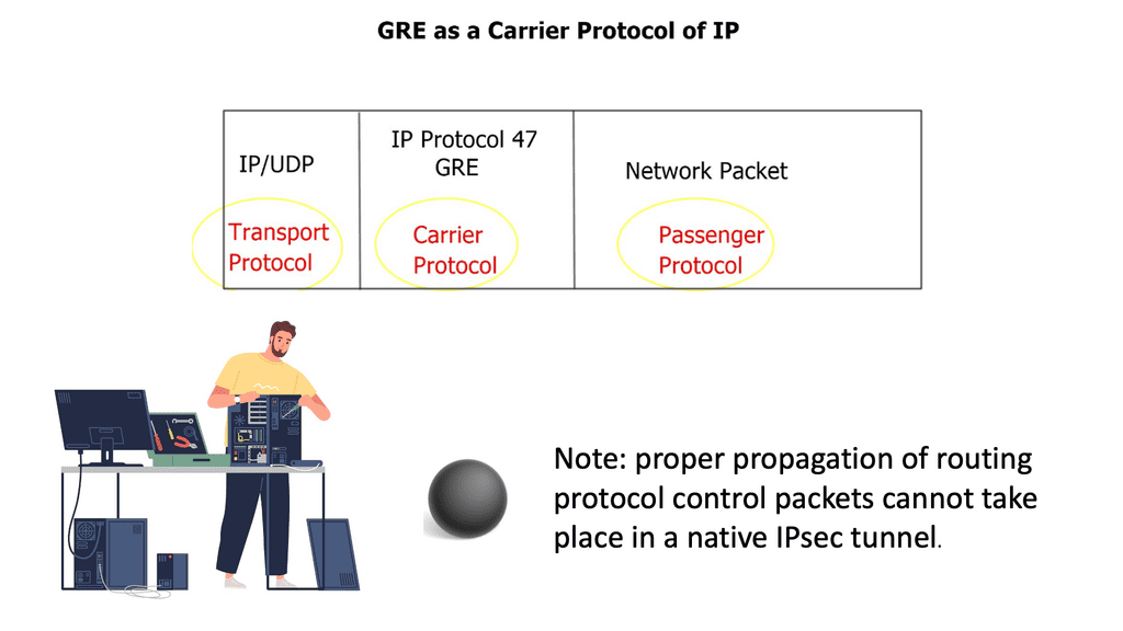
a. Simplified Configuration Management: With Nexus Switch Profiles, administrators can define a set of configurations for various network devices. These configurations can then be easily applied to multiple switches simultaneously, reducing the time and effort required for manual configuration tasks.

b. Scalability and Flexibility: Nexus Switch Profiles allow for easy replication of configurations across numerous switches, making them ideal for large-scale network deployments. Additionally, these profiles can be modified and updated according to the network’s evolving needs, ensuring flexibility and adaptability.
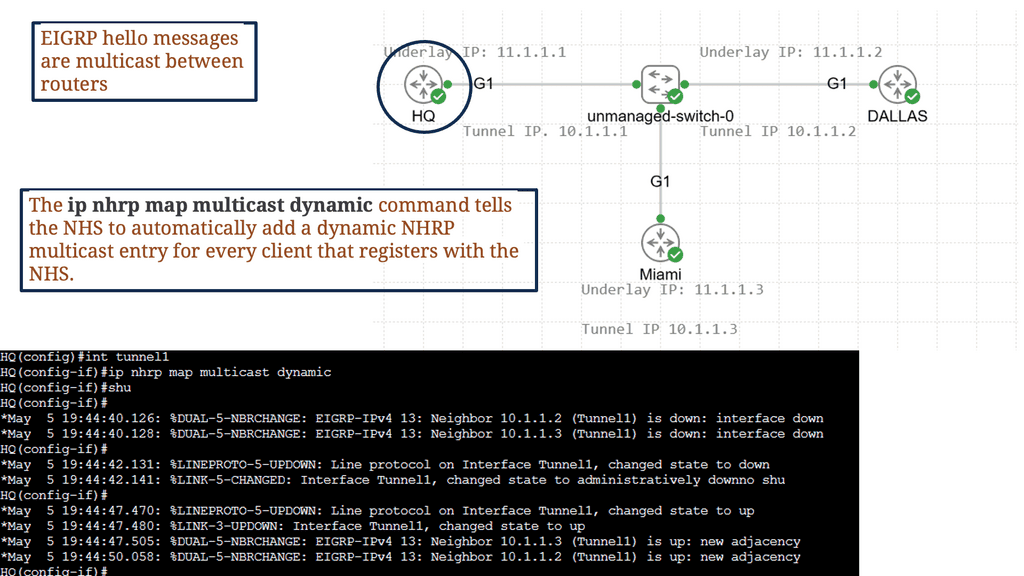
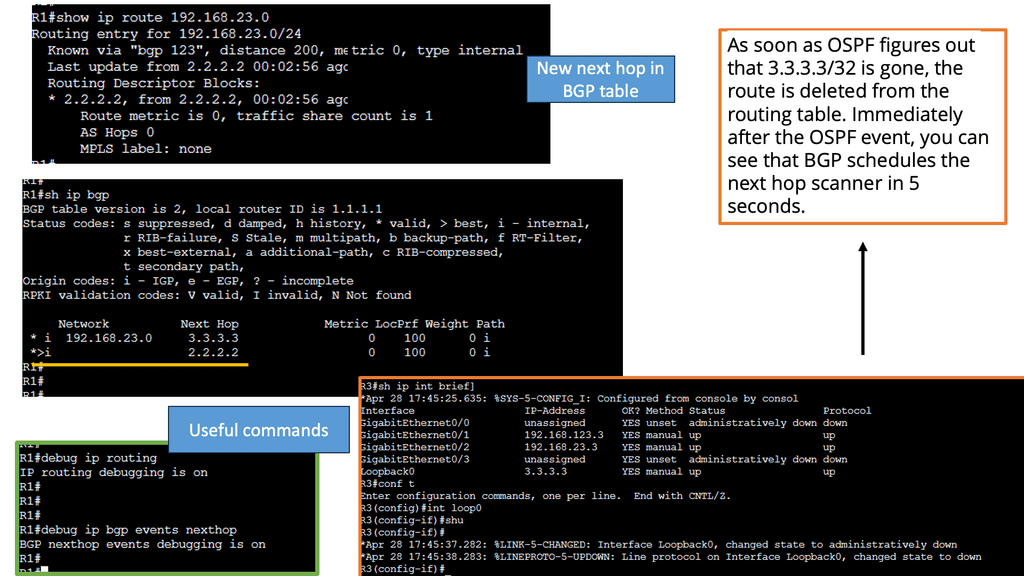
c. Enhanced Consistency and Compliance: Administrators can ensure consistent network behavior and compliance with organizational policies by enforcing a standardized set of configurations through Nexus Switch Profiles, which helps maintain network stability and security.

Understanding Virtual Routing and Forwarding

Virtual routing and forwarding, also known as VRF, is a mechanism that enables multiple virtual routing tables to coexist within a single physical router or switch. Each VRF instance operates independently, segregating network traffic and providing isolated routing domains. Organizations can achieve network segmentation by creating these virtual instances, allowing different departments or customers to maintain their distinct routing environments.

Real-World Applications of VRF

VRF finds applications in various scenarios across different industries. In large enterprises, VRF facilitates the segregation of network traffic between different departments, optimizing performance and security. Internet service providers (ISPs) utilize VRF to offer virtual private network services to their customers, ensuring secure and isolated connectivity. Moreover, VRF is instrumental in multi-tenant environments, enabling cloud service providers to offer isolated network domains to their clients.

VXLAN Fabric

While utilizing the same physically connected 3-stage Clos network, VXLAN fabrics introduce an abstraction level into the network that elevates workloads and the services they provide into another layer called the overlay. An encapsulation method such as Generic Routing Encapsulation (GRE) or MPLS (which adds an MPLS label) is used to accomplish this. In these tunneling mechanisms, packets are tunneled from one point to another utilizing the underlying network. A VXLAN header is added to IP packets containing a UDP header, a VXLAN header, and an IP header. VXLAN Tunnel Endpoints (VTEPs) are devices configured to encapsulate VXLAN traffic.

Flood and Learn Mechanism

At the heart of VXLAN lies the Flood and Learn mechanism, which plays a crucial role in efficiently forwarding network traffic. When a VM sends a frame to a destination VM residing in a different VXLAN segment, the frame is flooded across the VXLAN overlay network. The frame is efficiently distributed using multicast to all relevant VTEPs (VXLAN Tunnel Endpoint) within the same VXLAN segment. Each VTEP learns the MAC (Media Access Control) addresses of the VMs within its segment, allowing for optimized forwarding of subsequent frames.

Multicast plays a pivotal role in VXLAN Flood and Learn, offering several advantages over unicast or broadcast-based approaches. First, multicast enables efficient traffic distribution by replicating frames only to the relevant VTEPs within a VXLAN segment. This reduces unnecessary network overhead and enhances overall performance. Additionally, multicast allows for dynamic membership management, ensuring that VTEPs join and leave multicast groups as needed without manual configuration.

VXLAN Flood and Learn with Multicast has found widespread adoption in various use cases. Data center networks, particularly those with high VM density, benefit from the scalability and flexibility provided by VXLAN. Large-scale VM migrations and workload mobility can be seamlessly achieved by leveraging multicast without compromising network performance. Furthermore, VXLAN Flood and Learn enables efficient utilization of network resources, optimizing bandwidth usage and reducing latency.

Understanding BGP Route Reflection

BGP route reflection is a mechanism that alleviates the full mesh requirement in BGP networks. Establishing a full mesh of BGP peers in large-scale networks can become impractical, leading to increased complexity and resource consumption. Route reflection enables route information to be selectively propagated across BGP speakers, resulting in a more scalable and manageable network infrastructure.

To implement BGP route reflection, a network administrator must identify routers that will act as route reflectors. These routers are responsible for reflecting BGP updates from one client to another, ensuring the propagation of routing information without requiring a full mesh. Careful design considerations, such as route reflector hierarchy and cluster configuration, are essential for optimal scalability and performance.

Example: Data Center Fabric – FabricPath

Network devices are deployed in highly interconnected layers, represented as a fabric. Unlike traditional multitier architectures, a data center fabric effectively flattens the network architecture, reducing the distance between endpoints within the data center. An example of a data center fabric is FabricPath.

Cisco has validated FabricPath as an Intra-DC Layer 2 multipath technology. Design cases are also available where FabricPath is deployed for DCI ( Data Center Interconnect ). Regarding a FabricPath DCI option, design carefully over short distances with reliable interconnects, such as Dark Fiber or Protected Dense Wavelength Division Multiplexing (DWDM ).

FabricPath designs are suitable for a range of topologies. Unlike hierarchical virtual Port Channel ( vPC ) designs, FabricPath does not need to follow any topology. It can accommodate any design type: full mesh, partial mesh, hub, and spoke topologies.

Example: Data Center Fabric – Cisco ACI 

ACI Cisco is a software-defined networking (SDN) architecture that brings automation and policy-driven application profiles to data centers. By decoupling network hardware and software, ACI provides a flexible and scalable infrastructure to meet dynamic business requirements. It enables businesses to move from traditional, manual network configurations to a more intuitive and automated approach.
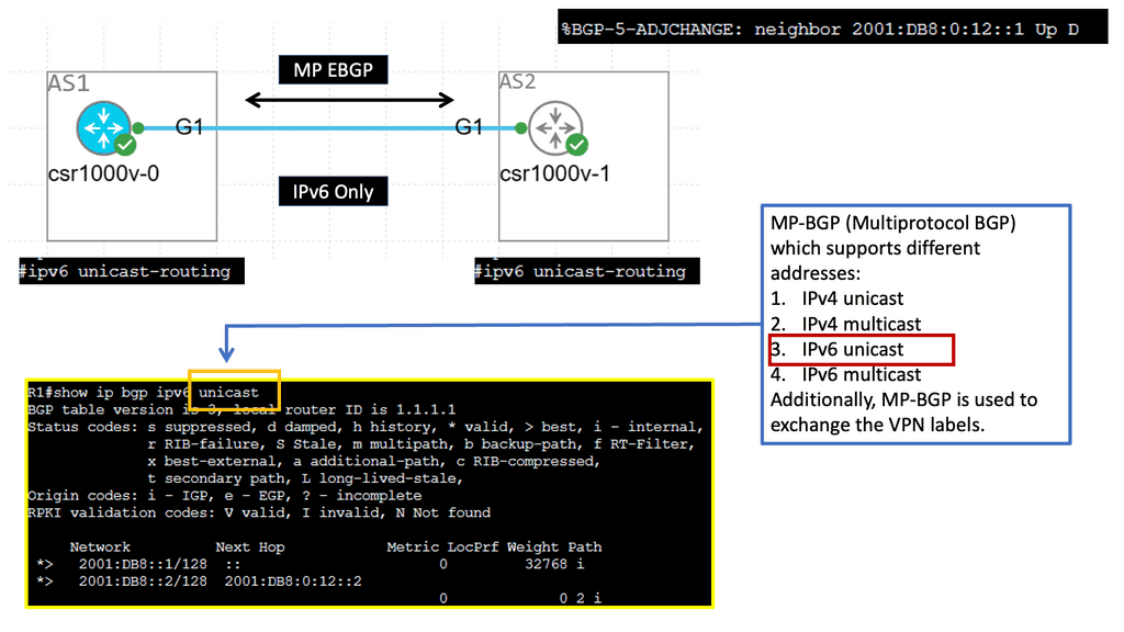
One of the defining features of Cisco ACI is its application-centric approach. It allows IT teams to define policies based on application requirements rather than individual network components. This approach simplifies network management, reduces complexity, and ensures that network resources are aligned with the needs of the applications they support.

SDN data center
Diagram: Cisco ACI fabric checking.

Related: Before you proceed, you may find the following posts helpful:

  1. What Is FabricPath
  2. Data Center Topologies
  3. ACI Networks
  4. Active Active Data Center Design
  5. Redundant Links

Data Center Fabric

Flattening the network architecture

In this current data center network design, network devices are deployed in two interconnected layers, representing a fabric. Sometimes, massive data centers are interconnected with three layers. Unlike conventional multitier architectures, a data center fabric flattens the network architecture, reducing the distance between endpoints within the data center. This design results in high efficiency and low latency. Very well suited for east-to-west traffic flows.

Data center fabrics provide a solid layer of connectivity in the physical network and move the complexity of delivering use cases for network virtualization, segmentation, stretched Ethernet segments, workload mobility, and various other services to an overlay that rides on top of the fabric.

When paired with an overlay, the fabric itself is called the underlay. The overlay could be deployed with, for example, VXLAN. To gain network visibility into user traffic, you would examine the overlay, and the underlay is used to route traffic between the overlay endpoints.

VXLAN, short for Virtual Extensible LAN, is a network virtualization technology that enables the creation of virtual networks over an existing physical network infrastructure. It provides a scalable and flexible approach to address the challenges posed by traditional VLANs, such as limited scalability, spanning domain constraints, and the need for manual configuration.

Guide on overlay networking with VXLAN

The following example shows VLXAN tunnel endpoints on Leaf A and Leaf B. The bridge domain is mapped to a VNI on G3 on both leaf switches. This enables a Layer 2 overlay for the two hosts to communicate. This VXLAN overlay goes across Spine A and Spine B.

Note that the Spine layer, which acts as the core network, a WAN network, or any other type of Routed Layer 3 network, has no VXLAN configuration. We have flattened the network while providing Layer 2 connectivity over a routed core.

VXLAN overlay
Diagram: VXLAN Overlay

Fabricpath Design: Problem Statement

Key Features of Cisco Fabric Path:

Transparent Interconnection: Cisco Fabric Path allows for creating a multi-path forwarding infrastructure that provides transparent Layer 2 connectivity between devices within a network. This enables the efficient utilization of available bandwidth and simplifies network design.

Scalability: With Cisco Fabric Path, organizations can quickly scale their network infrastructure to accommodate growing data loads. It supports up to 16 million virtual network segments, enabling seamless expansion of network resources without compromising performance.

Fault Tolerance: Cisco Fabric Path incorporates advanced fault-tolerant mechanisms like loop-free topology and equal-cost multipath routing. These features ensure high availability and resiliency, minimizing the impact of network failures and disruptions.

Traffic Optimization: Cisco Fabric Path employs intelligent load-balancing techniques to distribute traffic across multiple paths, optimizing network utilization and reducing congestion. This results in improved application performance and enhanced user experience.

The problem with traditional classical Ethernet is the flooding behavior of unknown unicasts and broadcasts and the process of MAC learning. All switches must learn all MAC addresses, leading to inefficient resource use. In addition, Ethernet has no Time-to-Live ( TTL ) value, and if precautions are not in place, it could cause an infinite loop.

data center fabric

Deploying Spanning Tree Protocol ( STP ) at Layer 2 blocks loops, but STP has many known limitations. One of its most significant flaws is that it offers a single topology for all traffic with one active forwarding path. Scaling the data center with classical Ethernet and spanning trees is inefficient as it blocks all but one path. With spanning trees’ default behavior, the benefits of adding extra spines do not influence bandwidth or scalability.

Possible alternatives

Multichassis EtherChannel 

To overcome these limitations, Cisco introduced Multichassis EtherChannel ( MEC ). MEC comes in two flavors: Virtual Switching System ( VSS ) with Catalyst 6500 series or Virtual Port Channel ( vPC ) with Nexus Series. Both offer active/active forwarding but present scalability challenges when scaling out Spine / Core layers. Additionally, complexity increases when deploying additional spines.

Multiprotocol Label Switching 

Another option would be to scale out with Multiprotocol Label Switching ( MPLS ). Replace Layer 2 switching with Layer 3 forwarding and MPLS with Layer 2 pseudowires. This type of complexity would lead to an operational nightmare. The prevalent option is to deploy Layer 2 multipath with THRILL or FabricPath. In intra-DC communication, Layer 2 and Layer 3 designs are possible in two forms: Traditional DC design and Switched DC design.

MPLS overlay

FabricPath VLANs use Conversational Learning, meaning a subset of MAC addresses is learned at the network’s edge. Conversation learning consists of a three-way handshake. Each interface learns the MAC addresses of interested hosts. Compared to classical Ethernet, each switch device learns all MAC addresses for that VLAN.

  1. Traditional DC design replaces hierarchical vPC and STP with FabricPath. The core, distribution, and access elements stay the same. The same layered hierarchical model exists, but with FabricPath in the core.
  2. Switched DC design based on Clos Fabrics. Integrate additional Spines for Layer 2 and Layer 3 forwarding.

Traditional data center design

what is data center fabric
Diagram: what is data center fabric


Fabric Path in the core replaces vPC. It still uses port channels, but the hierarchical vPC technology previously used to provide active/active forwarding is not required. Instead, designs are based on modular units called PODs; within each POD, traditional DC technologies exist, such as vPC. Active/active ( dual-active paths ) forwarding based on a two-node Spine, Hot Standby Router Protocol ( HSRP ), announces the virtual MAC of the emulated switch from each of the two cores. For this to work, implement vPC+ on the inter-spine peer links.


Switched data center design

Switched Fabric Data Center
Diagram: Switched Fabric Data Center

Each edge node has equidistant endpoints to each other, offering predictable network characteristics. From FabricPath’s outlook, the entire Spine Layer is one large Fabric-based POD. In the traditional model presented above, port and MAC address capacity are key factors influencing the ability to scale out. The key advantage of Clos-type architecture is that it expands the overall port and bandwidth capacity within each POD.

Implementing load balancing 4 wide spines challenges traditional First Hop Redundancy Protocol ( FHRP ) like HSRP, which works with 2 active pairs by default. Implementing load balancing 4 wide spines with VLANs allowed on certain links is possible but can cause link polarization

For optimized designs, utilize a redundancy protocol to work with a 4-node gateway. Deploy Gateway Load Balancing Protocol ( GLBP ) and Anycast FHRP. GLBP uses a weighting parameter that allows Address Resolution Protocol ( ARP ) requests to be answered by MAC addresses pointing to different routers. Anycast FHRP is the recommended solution for designs with 4 or more spine nodes.

FabricPath Key Points:

  • FabricPath removes the requirement for a spanning tree and offers a more flexible and scalable design to its vPC-based Layer 2 alternative. No requirement for a spanning tree, enabling Equal Cost Multipath ( ECMP ).

  • FabricPath no longer forwards using spanning tree. Offering designers bi-sectional bandwidth and up to 16-way ECMP. 16 x 10Gbps links equate to 2.56 terabits per second between switches.

  • Data Centers with FabricPath are easy to extend and scale.

  • Layer 2 troubleshooting tools for FabricPath including FabricPath PING and Traceroute can now test multiple equal paths.

  • Control plane based on Intermediate System-to-Intermediate System ( IS-IS ).

  • Loop prevention is now in the data plane based on the TTL field.

Summary: Data Center Fabric

In the fast-paced digital age, where data rules supreme, the backbone of reliable and efficient data processing lies within data center fabrics. These intricate systems of interconnections enable the seamless flow of data, ensuring businesses and individuals can harness technology’s power. In this blog post, we dived deep into the world of data center fabric, exploring its architecture, benefits, and role in shaping our digital landscape.

Understanding Data Center Fabric

Data center fabric refers to the underlying framework that connects various components within a data center, including servers, storage, and networking devices. It comprises a complex network of switches, routers, and interconnecting cables, all working to facilitate data transmission and communication.

The Architecture of Data Center Fabric

Data center fabrics adopt a leaf-spine architecture called a Clos network. This design consists of leaf switches that directly connect to servers and spine switches that interconnect the leaf switches. The leaf-spine architecture ensures high bandwidth, low latency, and scalability, allowing data centers to handle increasing workloads and traffic demands.

Benefits of Data Center Fabric

  • Enhanced Performance:

Data center fabrics offer improved performance by minimizing latency and providing high-speed connectivity. The low-latency nature of fabrics ensures quick data transfers, enabling real-time processing and reducing bottlenecks.

  • Scalability and Flexibility:

With the ever-growing data requirements of modern businesses, scalability is crucial. Data center fabrics allow adding or removing switches seamlessly, accommodating changing demands without disrupting operations. This scalability is a significant advantage, especially in cloud computing environments.

  • Improved Resilience and Redundancy:

Data center fabrics are designed to provide redundancy and fault tolerance. In case of a link or switch failure, the fabric’s distributed nature allows traffic to be rerouted dynamically, ensuring uninterrupted service availability. This resiliency is vital for mission-critical applications and services.

Hyper-Scale Data Centers:

Tech giants like Google, Facebook, and Amazon heavily rely on data center fabrics to support their massive workloads. These hyper-scale data centers utilize fabric architectures to handle the vast amounts of data millions of users worldwide generate.

Enterprise Data Centers:

Medium to large-scale enterprises leverage data center fabrics for efficient data processing and seamless connectivity. Fabric architectures enable these organizations to enhance their IT infrastructure, ensuring optimal performance and reliability.

Conclusion:

The data center fabric is the backbone of modern digital infrastructure, enabling rapid and secure data transmission. With its scalable architecture, enhanced performance, and fault-tolerant design, data center fabrics have become indispensable in the age of cloud computing, big data, and the Internet of Things. As technology evolves, data center fabrics will play a vital role in powering the digital revolution.

GRE over IPsec

Point-to-Point Generic Routing Encapsulation over IP Security

Point-to-Point Generic Routing Encapsulation over IP Security

Generic Routing Encapsulation (GRE) is a widely used encapsulation protocol in computer networking. It allows the transmission of diverse network protocols over an IP network infrastructure. In this blog post, we'll delve into the details of the GRE and its significance in modern networking.

GRE acts as a tunneling protocol, encapsulating packets from one network protocol within another. By creating a virtual point-to-point link, it facilitates the transmission of data across different network domains. This enables the interconnection of disparate networks, making GRE a crucial tool for securely building virtual private networks (VPNs) and connecting remote sites.

P2P GRE is a tunneling protocol that allows the encapsulation of various network layer protocols within IP packets. It provides a secure and reliable method of transmitting data between two points in a network. By encapsulating packets in IP headers, P2P GRE ensures data integrity and confidentiality.

IP Security (IPsec) plays a crucial role in enhancing the security of P2P GRE tunnels. By leveraging cryptographic algorithms, IPsec provides authentication, integrity, and confidentiality of data transmitted over the network. It establishes a secure channel between two endpoints, ensuring that data remains protected from unauthorized access and tampering.

Enhanced Network Security: P2P GRE over IP Security offers a robust security solution for organizations by providing secure communication channels across public and private networks. It allows for the establishment of secure connections between geographically dispersed locations, ensuring the confidentiality of sensitive data.

Improved Network Performance: P2P GRE over IP Security optimizes network performance by encapsulating and routing packets efficiently. It enables the transmission of data across different network topologies, reducing network congestion and enhancing overall network efficiency.

Seamless Integration with Existing Infrastructures: One of the key advantages of P2P GRE over IP Security is its compatibility with existing network infrastructures. It can be seamlessly integrated into existing networks without the need for significant architectural changes, making it a cost-effective solution for organizations.

Security Measures: Implementing P2P GRE over IP Security requires careful consideration of security measures. Organizations should ensure that strong encryption algorithms are utilized, proper key management practices are in place, and regular security audits are conducted to maintain the integrity of the network.

Scalability and Performance Optimization: To ensure optimal performance, network administrators should carefully plan and configure the P2P GRE tunnels. Factors such as bandwidth allocation, traffic prioritization, and Quality of Service (QoS) settings should be taken into account to guarantee the efficient operation of the network.

Highlights: Point-to-Point Generic Routing Encapsulation over IP Security

Generic Tunnelling – P2P GRE & IPSec

– P2P GRE is a tunneling protocol that allows the encapsulation of different network protocols within an IP network. It provides a secure and efficient mechanism for transmitting data between two network endpoints. By encapsulating packets, P2P GRE ensures that information is protected from external threats and remains intact during transmission.

– IPsec, on the other hand, is a suite of protocols that provides security services at the IP layer. It offers authentication, confidentiality, and integrity to IP packets, ensuring that data remains secure even when traversing untrusted networks. IPsec can be combined with P2P GRE to create a robust and secure communication channel.

– The combination of P2P GRE and IPsec brings several benefits to network administrators and organizations. Firstly, it enables secure communication between geographically dispersed networks, allowing for seamless connectivity. Additionally, P2P GRE over IPsec provides strong encryption, ensuring the confidentiality of sensitive data. It also allows for the creation of virtual private networks (VPNs), offering a secure and private network environment.

– P2P GRE over IPsec finds applications in various scenarios. One common use case is connecting branch offices of an organization securely. By establishing a P2P GRE over IPsec tunnel between different locations, organizations can create a secure network environment for their remote sites. Another use case is securely connecting cloud resources to on-premises infrastructure, enabling secure and seamless integration.

**The Role of GRE**

A: In GRE, packets are wrapped within other packets that use supported protocols, allowing the use of protocols not generally supported by a network. To understand this, consider the difference between a car and a ferry. On land, cars travel on roads, while ferries travel on water.

B: Usually, cars cannot travel on water but can be loaded onto ferries. In this analogy, terrain could be compared to a network that supports specific routing protocols and vehicles to data packets. Similarly, one type of vehicle (the car) is loaded onto a different kind of vehicle (the ferry) to cross terrain it could not otherwise.

GRE tunneling: how does it work?

GRE tunnels encapsulate packets within other packets. Each router represents the end of the tunnel. GRE packets are exchanged directly between routers. When routers are between forwarding packets, they use headers surrounding them rather than opening the encapsulated packets. Every packet of data sent over a network has the payload and the header. The payload contains the data being sent, while the headers contain information about the source and group of the packet. Each network protocol attaches a header to each packet.

Unlike load limits on automobile bridges, data packet sizes are limited by MTU and MSS. An MSS measurement only measures a packet’s payload, not its headers. Including the headers, the MTU measures the total size of a packet. Packets that exceed MTU are fragmented to fit through the network.

GRE configuration

GRE Operation

GRE is a layer three protocol, meaning it works at the IP level of the network. It enables a router to encapsulate packets of a particular protocol and send them to another router, where they are decapsulated and forwarded to their destination. This is useful for tunneling, where data must traverse multiple networks and different types of hardware.

GRE encapsulates data in a header containing information about the source, destination, and other routing information. The GRE header is then encapsulated in an IP header containing the source and destination IP addresses. When the packet reaches the destination router, the GRE header is stripped off, and the data is sent to its destination.

GRE over IPsec

**Understanding Multipoint GRE**

Multipoint GRE, or mGRE, is a tunneling protocol for encapsulating packets and transmitting them over an IP network. It enables virtual point-to-multipoint connections, allowing multiple endpoints to communicate simultaneously. By utilizing a single tunnel interface, mGRE simplifies network configurations and optimizes resource utilization.

One of Multipoint GRE’s standout features is its ability to transport multicast and broadcast traffic across multiple sites efficiently. It achieves this through a single tunnel interface, eliminating the need for dedicated point-to-point connections. This scalability and flexibility make mGRE an excellent choice for large-scale deployments and multicast applications.

Multipoint GRE & DMVPN:

DMVPN, as the name suggests, is a virtual private network technology that dynamically creates VPN connections between multiple sites without needing dedicated point-to-point links. It utilizes a hub-and-spoke architecture, with the hub as the central point for all communication. Using the Next Hop Resolution Protocol (NHRP), DMVPN provides a highly scalable and flexible solution for securely interconnecting sites.

Multipoint GRE, or mGRE, is a tunneling protocol my DMVPN uses to create point-to-multipoint connections. It allows multiple spokes to communicate directly with each other, bypassing the hub. By encapsulating packets within GRE headers, mGRE establishes virtual links between spokes, providing a flexible and efficient method of data transmission.

Google HA VPN

Understanding HA VPN

HA VPN is a highly scalable and redundant VPN solution provided by Google Cloud. It allows you to establish secure connections over the public internet while ensuring high availability and reliability. With HA VPN, you can connect your on-premises networks to Google Cloud, enabling secure data transfer and communication.

To begin configuring HA VPN, you must first set up a virtual private cloud (VPC) network in Google Cloud. This VPC network will serve as the backbone for your VPN connection. Next, you must create a VPN gateway and configure the necessary parameters, such as IP addresses, routing, and encryption settings. Google Cloud provides a user-friendly interface and comprehensive documentation to guide you through this process.

Once the HA VPN configuration is set up in Google Cloud, it’s time to establish connectivity with your on-premises networks. This involves configuring your on-premises VPN gateway or router to connect to the HA VPN gateway in Google Cloud. You must ensure that the IPsec VPN parameters, such as pre-shared keys and encryption algorithms, are correctly configured on both ends for a secure and reliable connection.

IPSec Security

Securing GRE:

IPsec, short for Internet Protocol Security, is a protocol suite that provides secure communication over IP networks. It operates at the network layer of the OSI model, offering confidentiality, integrity, and authentication services. By encrypting and authenticating IP packets, IPsec effectively protects sensitive data from unauthorized access and tampering.

Components of IPsec:

To fully comprehend IPsec, we must familiarize ourselves with its core components. These include the Authentication Header (AH), the Encapsulating Security Payload (ESP), Security Associations (SAs), and Key Management protocols. AH provides authentication and integrity, while ESP offers confidentiality and encryption. SAs establish the security parameters for secure communication, and Key Management protocols handle the exchange and management of cryptographic keys.

The adoption of IPsec brings forth a multitude of advantages for network security. First, it ensures data confidentiality by encrypting sensitive information, making it indecipherable to unauthorized individuals. Second, IPsec guarantees data integrity, as any modifications or tampering attempts would be detected. Additionally, IPsec provides authentication, verifying the identities of communicating parties, thus preventing impersonation or unauthorized access.

When IPsec and GRE are combined, they create a robust network security solution. IPsec ensures the confidentiality and integrity of data, while GRE enables the secure transmission of encapsulated non-IP traffic. This integration allows organizations to establish secure tunnels for transmitting sensitive information while extending their private networks securely.

Benefits of GRE over IPSEC:

Secure Data Transmission: By leveraging IPSEC’s encryption and authentication capabilities, GRE over IPSEC ensures the confidentiality and integrity of data transmitted over the network. This is particularly crucial when transmitting sensitive information, such as financial data or personal records.

Network Scalability: GRE over IPSEC allows organizations to create virtual private networks (VPNs) by establishing secure tunnels between remote sites. This enables seamless communication between geographically dispersed networks, enhancing collaboration and productivity.

Protocol Flexibility: GRE over IPSEC supports encapsulating various network protocols, including IPv4, IPv6, and multicast traffic. This flexibility enables the transmission of diverse data types, ensuring compatibility across different network environments.

The Role of VPNs

VPNs are deployed on an unprotected network or over the Internet to ensure data integrity, authentication, and encryption. Initially, VPNs were designed to reduce the cost of unnecessary leased lines. As a result, they now play a critical role in securing the internet and, in some cases, protecting personal information.

In addition to connecting to their corporate networks, individuals use VPNs to protect their privacy. Data integrity, authentication, and encryption through L2F, L2TP, GRE, or MPLS VPNs are impossible. However, IPsec can also benefit these protocols when combined with L2TP, GRE, and MPLS. These features make IPsec the preferred protocol for many organizations.

DMVPN over IPsec
Diagram: DMVPN over IPsec

GRE over IPsec

A GRE tunnel allows unicast, multicast, and broadcast traffic to be tunneled between routers and is often used to route traffic between different sites. A disadvantage of GRE tunneling is that it is clear text and offers no protection. Cisco IOS routers, however, allow us to encrypt the entire GRE tunnel, providing a safe and secure site-to-site tunnel.

RFC 2784 defines GRE (protocol 47), and RFC 2890 extends it. Using GRE, packets of any protocol (the payload packets) can be encapsulated over any other protocol (the delivery protocol) between two endpoints. Between the payload (data) and the delivery header, the GRE protocol adds its header (4 bytes plus options).

Tip:

GRE supports IPv4 and IPv6. If IPv4 or IPv6 endpoint addresses are defined, the outer IP header will be IPv4 or IPv6, respectively. In comparison to the original packet, GRE packets have the following overhead:

  • 4 bytes (+ GRE options) for the GRE header.
  • 20 bytes (+ IP options) for the outer IPv4 header (GRE over IPv4), or
  • 40 bytes (+ extension headers) for the outer IPv6 header (GRE over IPv6).

GRE over IPsec creates a new IP packet inside the network infrastructure device by encapsulating the original packets within GRE.

When GRE over IPsec is deployed in tunnel mode, the plaintext IPv4 or IPv6 packet is encapsulated into GRE. The tunnel source and destination IP addresses are then encapsulated in another IPv4 or IPv6 packet. An IPsec tunnel source and tunnel destination route the traffic to the destination with an additional outer IP header acting as a tunnel source and tunnel destination.

On the other hand, GRE over IPsec encapsulates plaintext IPv4 or IPv6 packets in GRE and then protects them with IPsec for confidentiality and integrity; the outer IP header with the source and destination addresses of the GRE tunnel enables packet routing.

IPsec site-to-site

An IPsec site-to-site VPN, also known as a gateway-to-gateway VPN, is a secure tunnel established between two or more remote networks over the internet. It enables organizations to connect geographically dispersed offices, data centers, or even cloud networks, creating a unified and secure network infrastructure. By leveraging IPsec, organizations can establish secure communication channels, ensuring confidentiality, integrity, and authentication of transmitted data.

GRE with IPsec

Advanced Topics

GETVPN:

– GetVPN, short for Group Encrypted Transport VPN, is a Cisco proprietary technology that provides secure site communication. It operates in the network layer and employs a key server to establish and distribute encryption keys to participating devices.

– This approach enables efficient and scalable deployment of secure VPNs across large networks. GetVPN offers robust security measures, including data confidentiality, integrity, and authentication, making it an excellent choice for organizations requiring high levels of security.

– When you run IPSec over a hub-and-spoke topology like DMVPN, the hub router has an IPSec SA with every spoke router. As a result, you are limited in the number of spoke routers you can use. Direct spoke-to-spoke traffic is supported in DMVPN, but when a spoke wants to send traffic to another spoke, it must first create an IPSec SA, which takes time.

Multicast traffic cannot be encapsulated with traditional IPSec unless first encapsulated with GRE.

GETVPN solves the scalability issue by using a single IPSec SA for all routers in a group. Multicast traffic is also supported without GRE.

Understanding IPv6 Tunneling

IPv6 tunneling is a mechanism that enables the encapsulation of IPv6 packets within IPv4 packets, allowing them to traverse an IPv4 network infrastructure. This allows for the coexistence and communication between IPv6-enabled devices over an IPv4 network. The encapsulated IPv6 packets are then decapsulated at the receiving end of the tunnel, restoring the original IPv6 packets.

Types of IPv6 Tunneling Techniques

There are several tunneling techniques used for IPv6 over IPv4 connectivity. Let’s explore a few prominent ones:

Manual IPv6 Tunneling: Manual IPv6 tunneling involves manually configuring tunnels on both ends. This method requires the knowledge of the source and destination IPv4 addresses and the tunneling protocol to be used. While it offers flexibility and control, manual configuration can be time-consuming and error-prone.

Automatic 6to4 Tunneling: Automatic 6to4 tunneling utilizes the 6to4 addressing scheme to assign IPv6 addresses to devices automatically. It allows IPv6 packets to be encapsulated within IPv4 packets, making them routable over an IPv4 network. This method simplifies the configuration process, but it relies on the availability of public IPv4 addresses.

Teredo Tunneling: Teredo tunneling is designed for IPv6 connectivity over IPv4 networks when the devices are located behind a NAT (Network Address Translation) device. It employs UDP encapsulation to transmit IPv6 packets over IPv4. Teredo tunneling can be helpful in scenarios where native IPv6 connectivity is unavailable.

Before you proceed, you may find the following posts helpful for pre-information:

  1. Dead Peer Detection
  2. IPsec Fault Tolerance
  3. Dynamic Workload Scaling 
  4. Cisco Switch Virtualization
  5. WAN Virtualization
  6. VPNOverview

Point-to-Point Generic Routing Encapsulation over IP Security

Guide on IPsec site to site

In this lesson, two Cisco IOS routers use IPSec in tunnel mode. This means the original IP packet will be encapsulated in a new IP packet and encrypted before sending it out of the network. For this demonstration, I will be using the following three routers.

R1 and R3 each have a loopback interface behind them with a subnet. We’ll configure the IPsec tunnel between these routers to encrypt traffic from 1.1.1.1/32 to 3.3.3.3/32. R2 is just a router in the middle, so R1 and R3 are not directly connected.

Notice with information 1 that we can’t ping the remote LAN. However, once the IPsec tunnel is up, we have reachability. Under the security associations, we have 4 packets encapsulated and encapsulated. However, I sent 5 pings. The first packet is lost to ARP.

ipsec tunnel
Diagram: IPsec Tunnel

IPsec relies on encryption and tunneling protocols to establish a secure connection between networks. The two primary components of IPsec are the IPsec tunnel mode and the IPsec transport mode. In tunnel mode, the entire IP packet is encapsulated within another IP packet, adding an extra layer of security. In contrast, the transport mode only encrypts the payload of the IP packet, leaving the original IP header intact.

To initiate a site-to-site VPN connection, the IPsec VPN gateway at each site performs a series of steps. These include negotiating the security parameters, authenticating the participating devices, and establishing a secure tunnel using encryption algorithms such as AES (Advanced Encryption Standard) or 3DES (Triple Data Encryption Standard). Once the tunnel is established, all data transmitted between the sites is encrypted, safeguarding it from unauthorized.

Back to basic with GRE tunnels

What is a GRE tunnel?

A GRE tunnel supplies connectivity to a wide variety of network layer protocols. GRE works by encapsulating and forwarding packets over an IP-based network. The authentic use of GRE tunnels provided a transport mechanism for non-routable legacy protocols such as DECnet and IPX. With GRE, we add header information to a packet when the router encapsulates it for transit on the GRE tunnel.

The new header information contains the remote endpoint IP address as the destination. The latest IP headers permit the packet to be routed between the two tunnel endpoints, and this is done without inspection of the packet’s payload.

After the packet reaches the remote endpoint, the GRE termination point, the GRE headers are removed, and the original packet is forwarded from the remote router. Both GRE and IPsec tunnels are used in solutions for SD WAN SASE and SD WAN Security. Both solutions abstract the complexity of configuring these technologies.

GRE Operation

GRE operates by encapsulating the original packet with a GRE header. This header contains information such as the source and destination IP addresses and additional fields for protocol identification and fragmentation support. Once the packet is encapsulated, it can be transmitted over an IP network, effectively hiding the underlying network details.

When a GRE packet reaches its destination, the receiving end decapsulates it, extracting the original payload. This process allows the recipient to receive the data as if it were sent directly over the underlying network protocol. GRE is a transparent transport mechanism, enabling seamless communication between disparate networks.

GRE Tunnel
Diagram: GRE tunnel example. Source is heficed

Guide on Point-to-Point GRE

Tunneling is putting packets into packets to transport them over a particular network. This is also known as encapsulation.

You might have two sites with IPv6 addresses on their LANs, but they only have IPv4 addresses when connected to the Internet. In normal circumstances, IPv6 packets would not be able to reach each other, but tunneling allows IPv6 packets to be routed on the Internet by converting IPv6 packets into IPv4 packets.

You might also want to run a routing protocol between your HQ and a branch site, such as RIP, OSPF, or EIGRP. By tunneling these protocols, we can exchange routing information between the HQ and branch routers.

When you configure a tunnel, you’re creating a point-to-point connection between two devices. We can accomplish this with GRE (Generic Routing Encapsulation). Let me show you a topology to demonstrate the GRE.

GRE configuration

In the image above, we have three routers connected. We have our headquarters router on the left side. On the right side, there is a “Branch” router. There is an Internet connection on both routers. An ISP router is located in the middle, on top. This topology can be used to simulate two routers connected to the Internet. A loopback interface represents the LAN on both the HQ and Branch routers.

EIGRP will be enabled on the loopback and tunnel interfaces. Through the tunnel interface, both routers establish an EIGRP neighbor adjacency. The next hop is listed as the tunnel interface in the routing table. We use GRE to tunnel our traffic, but it does not encrypt it like a VPN does. Our tunnel can be encrypted using IPSEC, one of the protocols.GRE without IPsec

Guide on Point-to-Point GRE with IPsec

A GRE tunnel allows unicast, multicast, and broadcast traffic to be tunneled between routers and is often used to send routing protocols between sites. GRE tunneling has the disadvantage of being clear text and unprotected. Cisco IOS routers, however, support IPsec encryption of the entire GRE tunnel, allowing a secure site-to-site tunnel. The following shows an encrypted GRE tunnel with IPsec.

We have three routers above. Each HQ and Branch router has a loopback interface representing its LAN connection. The ISP router connects both routers to “the Internet.” I have created a GRE tunnel between the HQ and Branch routers; all traffic between 172.16.1.0 /24 and 172.16.3.0 /24 will be encrypted with IPsec.

GRE with IPsec

For the IPsec side of things, I have configured an ISAKMP policy. In the example, I specify that I want 256-bit AES encryption and that we want a pre-shared key. We rely on Diffie-Hellman Group 5 for key exchange. The ISAKMP security association’s lifetime is 3600 seconds. The pre-shared key needs to be on both routers highlighted with a circle. Also, I created a transform-set called ‘TRANS’ that specifies we want ESP AES 256-bit and HMAC-SHA authentication.

Then, we create a crypto map that tells the router what traffic to encrypt and what transform set to use.

ipsec plus GRE

**How GRE and IPSec Work Together**

GRE and IPSec often work together to enhance network security. GRE provides the encapsulation mechanism, allowing the creation of secure tunnels between networks. IPSec, on the other hand, provides the necessary security measures, such as encrypting and authenticating the encapsulated packets. By combining both technologies’ strengths, organizations can establish secure and private connections between networks, ensuring data confidentiality and integrity.

**Benefits of GRE and IPSec**

The utilization of GRE and IPSec offers several benefits for network security. Firstly, GRE enables the transport of multiple protocols over IP networks, allowing organizations to leverage different network layer protocols without compatibility issues. Secondly, IPSec provides a robust security framework, protecting sensitive data from unauthorized access and tampering. GRE and IPSec enhance network security, enabling organizations to establish secure connections between geographically dispersed networks.

Topologies and routing protocol support

– Numerous technologies connect remote branch sites to HQ or central hub. P2P Generic Routing Encapsulation ( GRE network ) over IPsec is an alternative design to classic WAN technologies like ATM, Frame Relay, and Leased lines. GRE over IPsec is a standard deployment model that connects several remote branch sites to one or more central sites. Design topologies include the hub-and-spoke, partial mesh, and full mesh.

– Both partial and full-mesh topologies experience limitations in routing protocol support. A full mesh design is limited by the overhead required to support a design with a full mesh of tunnels. Following a complete mesh requirement, a popular design option would be to deploy DMVPN. Regarding the context of direct connectivity from branch to hub only, hub-and-spoke is by far the most common design.

Guide with DMVPN and GRE

The lab guide below shows a DMVPN network based on Generic Routing Encapsulation (GRE), which is the overlay. Specifically, we use GRE in point-to-point mode, which means deploying DMVPN Phase 1, a true VPN hub-and-spoke design, where all traffic from the spokes must go via the hub. With the command show dmvpn, we can see that two spokes are dynamically registered over the GRE tunnel; notice the “D” attribute.

The beauty of using DMPVN as a VPN technology is that the hub site does not need a specific spoke configuration as it uses GRE in multi-point mode. On the other hand, the spokes need to have a hub configuration with the command: IP nhrp nhs 192.168.100.11. IPsec encryption is optional with DMVPN. In the other command snippet, we are running IPsec encryption with the command: tunnel protection ipsec profile DMVPN_IPSEC_PROFILE.

DMVPN configuration
Diagram: DMVPN Configuration.

One of GRE’s primary use cases is creating VPNs. By encapsulating traffic within GRE packets, organizations can securely transmit data across public networks such as the Internet. This provides a cost-effective solution for connecting geographically dispersed sites without requiring dedicated leased lines.

Another use of the GRE is network virtualization. By leveraging GRE tunnels, virtual networks can be created isolated from the underlying physical infrastructure. This allows for more efficient resource utilization and improved network scalability.

**DMVPN (Dynamic Multipoint VPN)**

DMVPN is based on the principle of dynamic spoke-to-spoke tunneling, which allows for dynamic routing and scalability. It also allows for the creation of a dynamic mesh topology, allowing multiple paths between remote sites. This allows for increased redundancy and improved performance.

DMVPN also offers the ability to establish a secure tunnel over an untrusted network, such as the Internet. This is achieved with a series of DMVPN phases. DMVPN phase 3 offers better flexibility by using IPSec encryption and authentication, ensuring that all traffic sent over the tunnel is secure. This makes DMVPN an excellent choice for businesses connecting multiple sites over an unsecured network.

Dynamic Multipoint VPN
Diagram: Example with DMVPN. Source is Cisco

GRE Network: Head-end Architecture 

Single-tier and dual-tier

Head-end architectures include a single-tier head-end where the point-to-point GRE network and crypto functionality co-exist on the same device. Dual-tier designs are where the point-to-point GRE network and crypto functionality are not implemented on the same device. In dual-tier designs, the routing and GRE control planes are located on one device, while the IPsec control plane is housed on another.

what is generic routing encapsulation
Diagram: What is generic routing encapsulation?

Headend

Router

Crypto

Crypto IP

GRE  

GRE IP

Tunnel Protection

Single Tier

Headend

Static or Dynamic

Static

p2p GRE static

Static

Optional 


Branch

Static

Static or Dynamic

p2p GRE static

Static

Optional 

Dual Tier

Headend

Static or Dynamic

Static

p2p GRE static

Static

Not Valid


Branch

Static

Static or Dynamic

p2p GRE static

Static

Not Valid

“Tunnel protection” requires the same source and destination IP address for the GRE and crypto tunnels. Implementations of dual-tier separate these functions, resulting in the different IP addresses for the GRE and crypto tunnels. Tunnel protection is invalid with dual-tier mode.

GRE over IPsec

GRE (Generic Routing Encapsulation) is a tunneling protocol that encapsulates multiple protocols within IP packets, allowing the transmission of diverse network protocols over an IP network. On the other hand, IPSEC (IP Security) is a suite of protocols that provides secure communication over IP networks by encrypting and authenticating IP packets. Combining these two protocols, GRE over IPSEC offers a secure and flexible solution for transmitting network traffic over public networks.

Preliminary design considerations

Diverse multi-protocol traffic requirements force the use of a Generic Routing Encapsulation ( GRE ) envelope within the IPsec tunnel. The p2p GRE tunnel is encrypted inside the IPsec crypto tunnel. Native IPsec is not multi-protocol and lacks IP multicast or broadcast traffic support. As a result, proper propagation of routing protocol control packets cannot occur in a native IPsec tunnel.

However, OSPF design cases allow you to run OSPF network type non-broadcast and explicitly configure the remote OSPF neighbors, resulting in OSPF over the IPsec tunnel without GRE. With a GRE over IPsec design, all traffic between hub and branch sites is first encapsulated in the p2p GRE packet before encryption.

GRE over IPsec
Diagram: GRE over IPSec.

**GRE over IPSec Key Points**

Redundancy:

Redundant designs are implemented with the branch having two or more tunnels to the campus head. The head-end routers can be geographically separated or co-located. Routing protocols are used with redundant tunnels, providing high availability with dynamic path selection.

The head-end router can propagate a summary route ( 10.0.0.0/8 ) or a default route ( 0.0.0.0/0 ) to the branch sites, and a preferred routing metric will be used for the primary path. If OSPF is RP, the head-end selection is based on OSPF costs.

Recursive Routing:

Each branch must add a static route to their respective ISP IP addresses for each head-end. The static avoids recursive routing through the p2p GRE tunnel. Recursive routing occurs when the route to the GRE tunnel source outside the IP address of the opposing router is learned via a route with a next-hop of the inside IP address of the opposing p2p GRE tunnel.

Recursive routing causes the tunnel to flap and the p2p GRE packets to route into their p2p GRE tunnel. To overcome recursive routing, my best practice is to ensure that the outside tunnel is routed directly to ISP instead of inside the p2p GRE tunnel.

%TUN-5-RECURDOWN: Tunnel0 temporarily disabled due to recursive routing

Recursive routing and outbound interface selection pose significant challenges in tunnel or overlay networks. Therefore, routing protocols should be used with utmost caution over network tunnels. A router can encounter problems if it attempts to reach the remote router’s encapsulating interface (transport IP address) via the tunnel. Typically, this issue occurs when the transport network is advertised using the same routing protocol as the overlay network.

Routers learn the destination IP address for tunnel interfaces through recursive routing. First, the IP address of the tunnel’s destination is removed from the routing table, making it unreachable.

Split tunneling

If the head-end advertises a summary route to the branch, split tunneling is enabled on all packets not destined for the summary. Any packets not destined for the summary are split-tunneled to the Internet. For example, split tunneling is not used for the branch sites in a design where the head-end router advertises a default route ( 0.0.0.0/0 ) through the p2p GRE tunnel.

A key point: Additional information on Split tunneling.

Split tunneling is a networking concept that allows users to selectively route traffic from their local device to a local or remote network. It gives users secure access to corporate networks and other resources from public or untrusted networks. Split tunneling can also be used to reduce network congestion. For example, if a user is on a public network and needs to access a resource on a remote network, the user can set up a split tunnel to send only the traffic that needs to go over the remote network. This reduces the traffic on the public network, allowing it to perform more efficiently.

Control plane

Routing protocol HELLO packets initiated from the branch office force the tunnel to establish—routing protocol control plane packets to maintain and keep the tunnel up. HELLO packets provide a function similar to GRE keepaways. The HELLO routing protocol operates in layer 3, and GRE is maintained in layer 2.

 Branch router considerations

The branch router can have p2p GRE over IPSEC with a static or dynamic public address. The GRE and crypto tunnels are sourced from a static address with a static public IP address. With dynamic address allocation, the GRE is sourced from a loopback address privately assigned (non-routable), and the crypto tunnel is sourced from a dynamically assigned public IP address.

Closing Points on GRE with IPsec

GRE allows for the encapsulation of packets from various network protocols, providing a versatile solution for creating point-to-point links. Meanwhile, IPsec ensures these connections are secure, encrypting the data to protect it from interception and tampering. In this blog post, we’ll explore how to implement a point-to-point GRE tunnel secured by IPsec on Google Cloud, helping you create a robust and secure network architecture.

The first step in establishing a secure point-to-point link is setting up GRE tunnels. GRE is a tunneling protocol that encapsulates a wide variety of network layer protocols inside virtual point-to-point links. When configuring GRE on Google Cloud, you’ll need to create a Virtual Private Cloud (VPC) network, assign static IP addresses to your virtual machines, and configure the GRE tunnels on both ends. This setup allows for seamless data transfer across your network, regardless of underlying network infrastructure.

Once the GRE tunnel is established, the next step is to secure it using IPsec. IPsec provides encryption and authentication services for your data, ensuring that only authorized users can access it and that the data remains unaltered during transmission. On Google Cloud, you can configure IPsec by setting up Cloud VPN or using third-party tools to establish a secure IPsec tunnel. This involves generating and exchanging security keys, configuring security policies, and ensuring that your firewall rules allow IPsec traffic. With IPsec, your GRE tunnel becomes a secure conduit for your data, protected from potential threats.

One of the key advantages of using Google Cloud for your GRE and IPsec setup is the seamless integration with other Google Cloud services. Whether you’re connecting different regions, linking on-premises networks with cloud resources, or setting up a hybrid cloud environment, Google Cloud’s suite of services can enhance your network’s functionality and performance. Services like Google Cloud Interconnect, Cloud DNS, and Cloud Load Balancing can be incorporated into your architecture to optimize data flow, manage traffic, and ensure high availability.

Summary: Point-to-Point Generic Routing Encapsulation over IP Security

Point-to-Point Generic Routing Encapsulation (P2P GRE) over IP Security (IPsec) stands out as a robust and versatile solution in the vast realm of networking protocols and security measures. This blog post will delve into the intricacies of P2P GRE over IPsec, exploring its features, benefits, and real-world applications.

Understanding P2P GRE

P2P GRE is a tunneling protocol that encapsulates various network layer protocols over IP networks. It establishes direct communication paths between multiple endpoints, creating virtual point-to-point connections. By encapsulating data packets within IP packets, P2P GRE enables secure transmission across public or untrusted networks.

Exploring IPsec

IPsec serves as the foundation for securing network communications. It provides authentication, confidentiality, and integrity to protect data transmitted over IP networks. By combining IPsec with P2P GRE, organizations can achieve enhanced security and privacy for their data transmissions.

Benefits of P2P GRE over IPsec

– Scalability: P2P GRE supports the creation of multiple tunnels, enabling flexible and scalable network architectures.

– Versatility: The protocol is platform-independent and compatible with various operating systems and network devices.

– Efficiency: P2P GRE efficiently handles encapsulation and decapsulation processes, minimizing overhead and ensuring optimal performance.

– Security: Integrating IPsec with P2P GRE ensures end-to-end encryption, authentication, and data integrity, safeguarding sensitive information.

Real-World Applications

P2P GRE over IPsec finds extensive use in several scenarios:

– Secure Site-to-Site Connectivity: Organizations can establish secure connections between geographically dispersed sites, ensuring private and encrypted communication channels.

– Virtual Private Networks (VPNs): P2P GRE over IPsec forms the backbone of secure VPNs, enabling remote workers to access corporate resources securely.

– Cloud Connectivity: P2P GRE over IPsec facilitates secure connections between on-premises networks and cloud environments, ensuring data confidentiality and integrity.

Conclusion:

P2P GRE over IPsec is a powerful combination that offers secure and efficient communication across networks. Its versatility, scalability, and robust security features make it an ideal choice for organizations seeking to protect their data and establish reliable connections. By harnessing the power of P2P GRE over IPsec, businesses can enhance their network infrastructure and achieve higher data security.

BGP neighbor states

BGP Port 179 exploit Metasploit

BGP Port 179 Exploit Metasploit

In the world of computer networking, Border Gateway Protocol (BGP) plays a crucial role in facilitating the exchange of routing information between different autonomous systems (ASes). At the heart of BGP lies port 179, which serves as the communication channel for BGP peers. In this blog post, we will dive into the significance of BGP port 179, exploring its functionality, its role in establishing BGP connections, and its importance in global routing.

Port 179, also known as the Border Gateway Protocol (BGP) port, serves as a communication channel for routers to exchange routing information. It facilitates the establishment of connections between autonomous systems, enabling the efficient flow of data packets across the interconnected network.

Border Gateway Protocol (BGP) is a gateway protocol that enables the Internet to exchange routing information between autonomous systems (AS). This is accomplished through peering, and BGP uses TCP port 179 to communicate with other routers, known as BGP peers. Without it, networks would not be able to send and receive information with each other.

However, peering requires open ports to send and receive BGP updates that can be exploited. BGP port 179 exploit can be used with Metasploit, often referred to as port 179 BGP exploit Metasploit. Metasploit is a tool that can probe BGP to determine if there is a port 179 BGP exploit.

Highlights: BGP Port 179 Exploit Metasploit

BGP Port 179

BGP is often described as the backbone of the internet. It’s a routing protocol that facilitates the exchange of routing information between autonomous systems (AS), which are large networks or groups of networks under a common administration. Think of it as a sophisticated GPS for data packets, directing them through the most efficient paths across the global network.

### How BGP Works

At its core, BGP operates by maintaining a table of IP networks or ‘prefixes’ which designate network reachability among autonomous systems. When a data packet needs to traverse the internet, BGP determines the best path based on various factors such as path length, policies, and rules set by network administrators. This dynamic routing mechanism ensures resilience and efficiency, adapting to network changes and congestion to maintain effective communication.

Introducing BGP & TCP Port 179:

The Border Gateway Protocol (BGP) is a standardized routing protocol that provides scalability, flexibility, and network stability. IPv4 inter-organization connectivity was a primary design consideration in public and private networks. BGP is the only protocol used to exchange networks on the Internet, which has more than 940,000 IPv4 and 180,000 IPv6 addresses.

Because of the large size of its tables, BGP does not advertise incremental updates or refresh network advertisements like OSPF and IS-IS. Due to a link flap, BGP prefers network stability. Along with several BGP features, BGP also operates over TCP ports and gains the advantage of using TCP as its transport for stability.

**The Importance of TCP Port 179 in BGP**

TCP port 179 is not just any port; it’s the lifeline for BGP operations. This port is used to initiate and maintain BGP sessions between routers. When routers need to exchange routing information, they establish a TCP connection via port 179. This connection is critical for the stability and reliability of the internet, as it ensures that data packets are routed efficiently. Without the proper functioning of TCP port 179, BGP would be unable to perform its essential role, leading to disruptions in internet service and connectivity issues.

**Security Considerations for TCP Port 179**

Given its crucial role in internet operations, TCP port 179 is often a target for malicious activities. Unauthorized access to this port can lead to serious security breaches, including the hijacking of data routes or denial of service attacks. It is vital for network administrators to implement robust security measures to protect this port. This includes using firewalls, intrusion detection systems, and regular monitoring of network traffic to detect and respond to any suspicious activities promptly.

Port 179
Diagram: Port 179 with BGP peerings.

**BGP neighbor relationships**

– BGP uses TCP port 179 to communicate with other routers. TCP handles fragmentation, sequencing, and reliability (acknowledgment and retransmission). A recent implementation of BGP uses the do-not-fragment (DF) bit to prevent fragmentation.

– Because IGPs form sessions with hellos that cannot cross network boundaries (single hop only), they follow the physical topology. The BGP protocol uses TCP, which can cross network boundaries (i.e., multi-hop). Besides neighbor adjacencies that are directly connected, BGP can also form adjacencies that are multiple hops apart.

– An adjacency between two BGP routers is referred to as a BGP session. To establish the TCP session with the remote endpoint, the router must use an underlying route installed in the RIB (static or from any routing protocol).

EBGP vs IBGP

eBGP – Bridging Networks: eBGP, or external BGP, is primarily used for communication between different autonomous systems (AS). Autonomous systems are networks managed and controlled by a single organization. eBGP allows these autonomous systems to exchange routing information, enabling them to communicate and share data across different networks.

iBGP – Enhancing Internal Routing: Unlike eBGP, iBGP, or internal BGP, is used within a single autonomous system. It facilitates communication between routers within the same AS, ensuring efficient routing of data packets. iBGP enables the exchange of routing information between routers, allowing them to make informed decisions on the best path for data transmission.

While eBGP and iBGP serve the purpose of routing data, there are significant differences between the two protocols. The primary distinction lies in their scope: eBGP operates between different autonomous systems, whereas iBGP operates within a single AS. EBGP typically uses external IP addresses for neighbor relationships, while iBGP utilizes internal IP addresses.

Significance of TCP port 179

According to who originates the session, BGP uses different sources and destinations other than 179. Essentially, BGP is a client-server protocol based on TCP. To establish a connection with a TCP server, a TCP client first sends a TCP SYN packet with the destination port as the well-known port. A SYN request is essentially a request to open a session.

When the server permits the session, it will respond with a TCP SYN ACK stating that it acknowledges the request to open the session and wants to open it. The server uses the well-known port as the source port and a randomly negotiated destination port in this SYN-ACK response. The client acknowledges the server’s response with a TCP ACK in the last step of the three-way handshake.

From a BGP perspective, TCP clients and servers are routers. The “client” router initiates the BGP session by sending a request to the server with a destination port of 179 and a random source port X. Server responds with source port 179 and destination port X. Therefore, all client-server traffic uses destination 179, while server-client traffic uses source 179.

Port 179 and Security

BGP port 179 plays a significant role in securing BGP sessions. BGP routers implement various mechanisms to ensure the authenticity and integrity of the exchanged information. One such mechanism is TCP MD5 signatures, which provide a simple yet effective way to authenticate BGP peers. By enabling TCP MD5 signatures, routers can verify the source of BGP messages and prevent unauthorized entities from injecting false routing information into the network.

Knowledge Check: TCP MD5 Signatures

### The Need for TCP MD5 Signatures

As the internet grew, so did the complexity and number of threats targeting its infrastructure. One major concern is the integrity and authenticity of BGP sessions. Without protection, malicious actors can hijack BGP sessions, leading to traffic misdirection and data interception. TCP MD5 signatures help mitigate this risk by adding a layer of security. They provide a mechanism for authenticating BGP messages, ensuring that the data received is indeed from a trusted source.

### How TCP MD5 Signatures Work

TCP MD5 signatures operate by hashing the TCP segment, including the BGP message, using the MD5 algorithm. Both the sender and receiver share a secret key, which is used in the hashing process. When a BGP message is received, the receiver computes the MD5 hash using the same secret key. If the computed hash matches the one sent with the message, the message is considered authentic. This method effectively prevents unauthorized entities from injecting malicious traffic into BGP sessions.

Advanced BGP TopicS

Understanding BGP Next Hop Tracking:

BGP Next Hop Tracking is a mechanism that enables routers to track the reachability of the next hop IP address. When a route is learned via BGP, the router verifies the reachability of the next hop and updates its routing table accordingly. This information is crucial for making accurate routing decisions and preventing traffic blackholing or suboptimal routing paths.

By utilizing BGP Next Hop Tracking, network operators can enjoy several benefits. First, it enhances routing stability by ensuring that only reachable next hops are used for forwarding traffic. This helps avoid routing loops and suboptimal paths.

Second, it provides faster convergence during network failures by quickly detecting and updating routing tables based on the reachability of next hops. Lastly, BGP Next Hop Tracking enables better troubleshooting capabilities by identifying faulty or unreachable next hops, allowing network administrators to take appropriate actions.

Once those 5 seconds have expired, the next hop address will be changed to 2.2.2.2 (R2) and added to the routing table. This process is much faster than the BGP scanner, which runs every 60 seconds.

Here’s what the BGP table now looks like:

Each route in the BGP table must have a reachable next hop. Otherwise, the route cannot be used. Every 60 seconds, BGP checks all routes in the BGP table. The BGP scanner calculates the best path, checks the next hop addresses, and determines if the next hops can be reached. For performance reasons, 60 seconds is long. When something goes wrong with a next hop during the 60 seconds between two scans, we have to wait until the next scan begins to resolve the issue. In the meantime, we may have black holes and/or routing loops.

The next hop tracking feature in BGP reduces convergence times by monitoring changes in the next hop address in the routing table.

The next hop scan is delayed by 5 seconds after detecting a change. Notice the 5-second timer in the images above. The next hop tracking system also supports dampening penalties. Next-hop scans that keep changing in the routing table are delayed.

Understanding BGP Route Reflection:

BGP route reflection is a technique used in BGP networks to address the scalability issues that arise when multiple routers are involved in the routing process. It allows for the efficient distribution of routing information without overwhelming the network with unnecessary updates. Network administrators can optimize their network’s performance and stability by understanding the basic principles of BGP route reflection.

Enhanced Scalability: BGP route reflection provides a scalable solution for large networks by reducing the number of BGP peering relationships required. This leads to simplified network management and improved performance.

Reduced Resource Consumption: BGP route reflection eliminates the need for full mesh connectivity between routers. This reduces resource consumption, such as memory and processing power, resulting in cost savings for network operators.

Improved Convergence Time: BGP route reflection improves overall network convergence time by reducing the propagation delay of routing updates. This is achieved by eliminating the need for full route propagation across the entire network, resulting in faster convergence and improved network responsiveness.

Example: MP-BGP with IPv6

Understanding MP-BGP

MP-BGP, short for Multiprotocol Border Gateway Protocol, is an extension of the traditional BGP protocol. It enables the simultaneous routing and exchange of multiple network layer protocols. MP-BGP facilitates smooth transition and interoperability between these protocols by supporting the coexistence of IPv4 and IPv6 addresses within the same network infrastructure.

IPv6, the successor to IPv4, offers a vast address space, improved security features, and enhanced mobility support. Its 128-bit address format allows for an astronomical number of unique addresses, ensuring the internet’s future scalability. With MP-BGP, organizations can harness the full potential of IPv6 by seamlessly integrating it into their existing network infrastructure.

To establish MP-BGP with IPv6 adjacency, several steps need to be followed. First, ensure that your network devices support MP-BGP and IPv6 routing capabilities. Next, configure the appropriate MP-BGP address families and attributes. Establish IPv6 peering sessions between BGP neighbors and enable the exchange of IPv6 routing information. Finally, verify the connectivity and convergence of the MP-BGP with IPv6 adjacency setup.

Related: Before you proceed, you may find the following posts helpful:

  1. IP Forwarding
  2. BGP SDN
  3. Redundant Links
  4. IPv6 Host Exposure
  5. Forwarding Routing Protocols
  6. Cisco DMVPN
  7. Dead Peer Detection


BGP Port 179 Exploit Metasploit

BGP Port 179: The Communication Channel

Port 179 is the well-known port for BGP communication, acting as the gateway for BGP messages to flow between BGP routers. BGP, a complex protocol, requires a reliable and dedicated port to establish connections and exchange routing information. By utilizing port 179, BGP ensures its communication is secure and efficient, enabling routers to establish and maintain BGP sessions effectively.

Establishing BGP Connections

When two BGP routers wish to connect, they initiate a TCP connection on port 179. This connection allows the routers to exchange BGP update messages containing routing information such as network prefixes, path attributes, and policies. Routers build a comprehensive view of the network’s topology by exchanging these updates and making informed decisions on route traffic.

**Section 1: The Basics of BGP Neighbors**

At its core, BGP neighbors—often called peers—are routers that have been configured to exchange BGP routing information. This exchange is essential for maintaining a coherent and functioning network topology. Establishing these neighbor relationships is the first step in building a robust BGP infrastructure. The process involves configuring specific IP addresses and using unique Autonomous System Numbers (ASN) to identify each participating network.

**Section 2: Configuration Steps for Establishing BGP Neighbors**

To establish a BGP neighbor relationship, network administrators must follow a series of configuration steps. First, ensure that both routers can reach each other over the network. This often involves configuring static routes or using an internal routing protocol. Next, initiate the BGP process by specifying the ASN for each router. Finally, declare the IP address of the neighboring router and confirm the configuration. This setup allows the routers to begin the exchange of routing information.

BGP port 179

Guide: BGP Port 179

In the following lab guide on port 179, we have two BGP peers labeled BGP Peer 1 and BGP Peer 2. These BGP peers have one Gigabit Ethernet link between them. I have created an iBGP peering between the two peers, where the AS numbering is the same for both peers. 

Note:

Remember that a full mesh iBGP peering is required within an AS because iBGP routers do not re-advertise routes learned via iBGP to other iBGP peers. This is called the split horizon rule and is a routing-loop-prevention mechanism. Since we have two iBGP peers, this is fine. The BGP peerings are over TCP port 179, and I have redistributed connected so we have a route in the BGP table.

Port 179
Diagram: Port 179 with BGP peerings.

BGP Neighbor States

Unlike IGPs such as EIGRP and OSPF, BGP establishes sessions differently. In IGPs, neighbors are dynamically discovered as they bootstrap themselves to the topology. To peer with another BGP speaker, BGP speakers must explicitly be configured to do so. Furthermore, BGP must wait for a reliable connection to be established before proceeding. To overcome some issues with its predecessor, EGP, BGP was enhanced to address this requirement.

For two routers to establish this connection, both sides must have an interface configured for BGP and matching BGP settings, such as an Autonomous System number. Once the two routers have established a BGP neighbor relationship, they exchange routing information and can communicate with each other as needed.

BGP neighbor states represent the different stages of the relationship between BGP routers. These states are crucial in establishing and maintaining connections for exchanging routing information. Idle, Connect, OpenSent, and Established are the four neighbor states. Each state signifies a specific phase in the BGP session establishment process.

BGP neighbor states

  1. Idle State:

The first state in the BGP neighborship is the Idle state. In this state, a BGP router does not know any neighboring routers. It is waiting to establish a connection with a potential BGP peer. When a router is in the Idle state, it periodically sends out keepalive messages to potential peers, hoping to initiate the neighborship process.

  1. Connect State:

Once a router receives a keepalive message from a potential BGP neighbor, it transitions to the Connect state. The router attempts to establish a TCP connection with the neighboring router in this state. The Connect state lasts until the TCP connection setup is successful, after which the router moves to the OpenSent state.

  1. OpenSent State:

In the OpenSent state, the BGP router sends a neighboring router an Open message containing information about its capabilities and parameters. The router waits for a response from the neighbor. If the received Open message is acceptable, the router moves to the OpenConfirm state.

  1. OpenConfirm State:

In the OpenConfirm state, BGP routers exchange Keepalive messages to confirm that the TCP connection works correctly. The routers also negotiate various BGP parameters during this state. Once both routers have confirmed the connection, they move to the Established state.

  1. Established State:

The Established state is the desired state for BGP neighborship. The routers have successfully established a BGP peering relationship in this state and are actively exchanging routing information. They exchange updates, keepalives, and notifications, enabling them to make informed routing decisions. This state is crucial for the stability and integrity of the overall BGP routing infrastructure.

BGP Neighbor Relationship

Below, the BGP state moves from Idle to Active and OpenSent. Some Open messages are sent and received; the BGP routers exchange some of their capabilities. From there, we move to the OpenConfirm and Established state. Finally, you see the BGP neighbor as up. The output of these debug messages is friendly and easy to read. If, for some reason, your neighbor’s adjacency doesn’t appear, these debugs can be helpful to solve the problem.

BGP neighbor Relationship

Port Numbers

Let’s go back to the basics for just a moment. First, we have port numbers, which represent communication endpoints. Port numbers are assigned 16-bit integers (see below) that identify a specific process or network service running on your network. These are not assigned randomly, and IANA is responsible for internet protocol resources, including registering used port numbers for well-known internet services.

  • Well Known Ports: 0 through 1023.
  • Registered Ports: 1024 through 49151.
  • Dynamic/Private: 49152 through 65535.

So, we have TCP port numbers and UDP port numbers. We know TCP enables hosts to establish a connection and exchange data streams reliably. Depending on the application, TCP Port 179 may use a defined protocol to communicate. For example, BGP is an application that uses TCP Port 179.

BGP chose this port for a good reason. TCP guarantees data delivery compared to UDP, and packets will be delivered on port 179 in the same order they were sent. So, we have guaranteed communication on TCP port 179, compared to UDP port 179. UDP port 179 would not have guaranteed communication in the same way as TCP.

UDP vs. TCP

UDP and TCP are internet protocols but have different features and applications. UDP, or User Datagram Protocol, is a lightweight and fast protocol used for applications that do not require reliable data transmission. UDP is a connectionless protocol that does not establish a dedicated end-to-end connection before sending data. Instead, UDP packets are sent directly to the recipient without any acknowledgment or error checking.

TCP vs UDP

Knowledge Check: TCP vs UDP

UDP, often referred to as a “connectionless” protocol, operates at the transport layer of the Internet Protocol Suite. Unlike TCP, UDP does not establish a formal connection between the sender and receiver before transmitting data. Instead, it focuses on quickly sending smaller packets, known as datagrams, without error-checking or retransmission mechanisms. This makes UDP a lightweight and efficient protocol ideal for applications where speed and minimal overhead are crucial.

**The Reliability of TCP**

In contrast to UDP, TCP is a “connection-oriented” protocol that guarantees reliable data delivery. By employing error-checking, acknowledgment, and flow control, TCP ensures that data is transmitted accurately and in the correct order. This reliability comes at the cost of increased overhead and potential latency, making TCP more suitable for applications that prioritize data integrity and completeness, such as file transfers and web browsing.

**Key Differences Between TCP and UDP**

The primary differences between TCP and UDP lie in their reliability, connection orientation, and speed. TCP’s connection-oriented approach ensures reliable data transfer with error correction, making it slower but more accurate. In contrast, UDP’s connectionless nature allows for quick transmission, sacrificing reliability for speed.

Another difference is in how they handle data flow. TCP uses flow control mechanisms to prevent network congestion, while UDP does not, allowing it to send data without waiting for acknowledgments. This makes TCP more suitable for applications requiring stable connections, whereas UDP is better for scenarios needing rapid data exchange.

**Applications and Use Cases**

Understanding when to use TCP and UDP is essential for optimizing network performance. TCP’s reliability makes it perfect for applications like web servers, email clients, and FTP services, where data integrity is crucial. On the other hand, UDP’s speed is beneficial for live broadcasts, online gaming, and voice communication, where delays can disrupt the user experience.

Use Cases and Applications

1. UDP:

– Real-time streaming: UDP’s low latency and reduced overhead suit real-time applications like video and audio streaming.

– Online gaming: The fast-paced nature of online gaming benefits from UDP, providing quick updates and responsiveness.

– DNS (Domain Name System): UDP is commonly used for DNS queries, where quick responses are essential for efficient web browsing.

DNS Root Servers

2. TCP:

– Web browsing: TCP’s reliability ensures that web pages and their resources are fully and accurately loaded.

– File transfers: TCP’s error-checking and retransmission mechanisms guarantee the successful delivery of large files.

– Email delivery: TCP’s reliability ensures that emails are transmitted without loss or corruption.

The TCP 3-Way Handshake

TCP, or Transmission Control Protocol, is a more reliable protocol for applications requiring error-free data transmission and guaranteed message delivery. TCP is a connection-oriented protocol that establishes a dedicated end-to-end connection between the sender and receiver before sending data. TCP uses a three-way handshake to establish a connection and provides error checking, retransmission, and flow control mechanisms to ensure data is transmitted reliably and efficiently.

TCP Handshake
Diagram: TCP Handshake

In summary, UDP is a lightweight and fast protocol suitable for applications that do not require reliable data transmissions, such as real-time streaming media and online gaming. TCP is a more reliable protocol ideal for applications requiring error-free data transmissions and guaranteed message delivery, such as web browsing, email, and file transfer.

BGP and TCP Port 179

In the context of BGP, TCP is used to establish a connection between two routers and exchange routing information. When a BGP speaker wants to connect with another BGP speaker, a TCP SYN message is sent to the other speaker. If the other speaker is available and willing to join, it sends a SYN-ACK message. The first speaker then sends an ACK message to complete the connection.

Once the connection is established, the BGP speakers can exchange routing information. BGP uses a set of messages to exchange information about the networks that each speaker can reach. The messages include information about the network prefix, the path to the network, and various attributes that describe the network.

Guide: Filtering TCP Port 179

The following will display the effects of filtering BGP port 179. Below is a simple design of 2 BGP peers—plain and simple. The routers use the directly connected IP addresses for the BGP neighbor adjacency. However, we have a problem: the BGP neighbor relationship is down, and we are not becoming neighbors. What could be wrong? We use the directly connected interfaces so nothing could go wrong except for L2/L2 issues.

Guide: BGP Update Messages

In the following lab guide, you will see we have two BGP peers. There is also a packet capture that displays the BGP update messages. BGP uses source and destination ports other than 179, depending on who originates the session. BGP is a standard TCP-based protocol that runs on client and server computers.

Port 179
Diagram: BGP peering operating over TCP Port 179

A successful TCP connection must exist before negotiating a BGP session between two peers. TCP provides a reliable transmission medium between the two peers and allows the exchange of BGP-related messages. A broken TCP connection also breaks the BGP session. BGP sessions are not always established after successful TCP connections.

1: – In BGP, the session establishment phase operates independently of TCP, i.e., BGP rides on top of TCP. As a result, two peers may form a TCP connection but disagree on BGP parameters, resulting in a failed peering attempt. The BGP FSM oscillates between IDLE, ACTIVE, and CONNECT states while establishing the TCP connection.

2: – To establish a connection with a TCP server, a TCP client first sends a TCP SYN packet with the destination port as the well-known port. In this first SYN, we are requesting to open a session. The server will reply with a TCP SYN ACK if it permits the session to open. It also wants to open a session. The source port of this SYN-ACK response is a well-known port, and the destination port is randomly chosen. After the three-way handshake, the client responds to the server with a TCP ACK, acknowledging the server’s response.

3: – As far as BGP is concerned, TCP clients and servers are routers. When the “client” router initiates the BGP connection, it sends a request to the server with a destination port 179 and a random X source port. The server then responds with a source port of 179 and a destination port of X. Consequently, all client-to-server traffic uses destination 179, while all server-to-client traffic uses source 179.

The following Wireshark output shows a sample BGP update message. Notice the Dst Port: 179 highlighted in red.

BGP update message
Diagram: BGP update message. Source is Wireshark

To achieve reliable delivery, developers could either build a new transport protocol or use an existing one. The BGP creators leveraged TCP’s already robust reliability mechanisms instead of reinventing the wheel. This integration with TCP creates two phases of BGP session establishment:

  • TCP connection establishment phase
  • BGP session establishment phase

BGP uses a finite state machine (FSM) throughout the two phases of session establishment. In computing, a finite state machine is a construct that allows an object – the machine here – to operate within a fixed number of states. There is a specific purpose and set of operations for each state. The machine exists in only one of these states at any given moment. Input events trigger state changes. BGP’s FSM has six states in total. The following three states of BGP’s FSM pertain to TCP connection establishment:

  • Idle
  • Connect
  • Active

TCP messages are exchanged in these states for reliable delivery of BGP messages. After the TCP connection establishment phase, BGP enters the following three states of the BGP FSM, which pertain to the BGP session establishment phase:

  • Opensent
  • Openconfirm
  • Established

In these states, BGP exchanges messages related to the BGP session. The OPENSENT and OPENCONFIRM states correspond to the exchange of BGP session attributes between the BGP speakers. The ESTABLISHED state indicates the peer is stable and can accept BGP routing updates.

Together, these six states make up the entire BGP FSM. BGP maintains a separate FSM for each intended peer. Upon receiving input events, a peer transitions between these states. When a TCP connection is successfully established in the CONNECT or ACTIVE states, the BGP speaker sends an OPEN message and enters the OPENSENT state. An error event could cause the peer to transition to IDLE in any state.

TCP Connection Establishment Phase

Successful TCP connections are required before negotiating a BGP session between two peers. Over TCP, BGP-related messages can be exchanged reliably between two peers. A broken TCP connection also breaks the BGP session. BGP sessions are not permanently established after successful TCP connections.

Because BGP operates independently within a TCP connection, it “rides” on top of TCP. Peering attempts can fail when two peers agree on TCP parameters but disagree on BGP parameters. While establishing the TCP connection, the BGP FSM oscillates between IDLE, ACTIVE, and CONNECT states.

TCP is a connection-oriented protocol. This means TCP establishes a connection between two speakers, ensuring the information is ordered and delivered reliably. To create this connection, TCP uses servers and clients.

  • Clients connect to servers, making them the connecting side
  • Servers listen for incoming connections from prospective clients

TCP uses port numbers to identify the services and applications a server hosts. HTTP traffic uses TCP port 80, one of the most well-known. Clients initiate connections to these ports to access a specific service from a TCP server. Randomly generated TCP port numbers will be used by TCP clients to source their messages.

Whenever a TCP connection is made, a passive side waits for a connection, and an active side tries to make the connection. The following two methods can be used to open or establish TCP connections:

  • Passive Open
  • Active Open

A passive open occurs when a TCP server accepts a TCP client’s connection attempts on a specific TCP port. A WebServer, for instance, is configured to accept connections on TCP port 80, also referred to as “listening” on TCP port 80.

Active open occurs when a TCP client attempts to connect to a specific port on a TCP server. In this case, Client A can initiate a connection request to connect to the Web Server’s TCP Port 80.

To establish and manage a TCP connection, clients and servers exchange TCP control messages. Messages sent in TCP/IP packets are characterized by control bits in the TCP header. As shown in the Wireshark capture below, the SYN and ACK bits in the TCP header of the TCP/IP packet play a crucial role in the basic setup of the TCP connection.

Source: PacketPushers

The SYN bit indicates an attempt to establish a connection. To ensure reliable communication, it synchronizes TCP sequence numbers. An ACK bit suggests that a TCP message has been acknowledged. Reliability is based on the requirement that messages be acknowledged.

TCP connections are generally established by exchanging three control messages:

    • The client initiates an active open by sending a TCP/IP packet with the SYN bit set in the TCP header. This is a SYN message.
    • The server responds with its SYN message (the SYN bit is set in the TCP header), resulting in a passive open. The server also acknowledges the client’s SYN segment by indicating the ACK bit in the same control message. Since both SYN and ACK bits are set in the same message, this message is called the SYN-ACK message.
    • The Client responds with a TCP/IP packet, with the ACK bit set in the TCP header, to acknowledge that it received the Server’s SYN segment.

A TCP three-way handshake involves exchanging control messages or segments. Once the handshake is completed, a TCP connection has been established, and data can be exchanged between the devices.

BGP’s three-way handshake is performed as follows:

  1. BGP speakers register the BGP process on TCP port 179 and listen for connection attempts from configured clients.
  2. As the TCP client, one speaker performs an active open by sending a SYN packet destined to the remote speaker’s TCP port 179. The packet is sourced from a random port number.
  3. The remote speaker, acting as a TCP server, performs a passive open by accepting the SYN packet from the TCP client on TCP port 179 and responding with its own SYN-ACK packet.
  4. The client speaker responds with an ACK packet, acknowledging it received the server’s SYN packet.
 

Bonus Content: What Is BGP Hijacking?

A BGP hijack occurs when attackers maliciously reroute Internet traffic. The attacker accomplishes this by falsely announcing ownership of IP prefixes they do not control, own, or route. When a BGP hijack occurs, all the signs on a stretch of the freeway are changed, and traffic is redirected to the wrong exit.

The BGP protocol assumes that interconnected networks are telling the truth about which IP addresses they own, so BGP hijacking is nearly impossible to stop. Imagine if no one watched the freeway signs. The only way to tell if they had been maliciously changed was by observing that many cars ended up in the wrong neighborhoods. To hijack BGP, an attacker must control or compromise a BGP-enabled router that bridges two autonomous systems (AS), so not just anyone can do so.

Inject False Routing Information

BGP hijacking can occur when an attacker gains control over a BGP router and announces false routing information to neighboring routers. This misinformation causes the routers to redirect traffic to the attacker’s network instead of the intended destination. The attacker can then intercept, monitor, or manipulate the traffic for malicious purposes, such as eavesdropping, data theft, or launching distributed denial of service (DDoS) attacks.

Methods for BGP Hijacking

There are several methods that attackers can use to carry out BGP hijacking. One common technique is prefix hijacking, where the attacker announces a more specific IP address prefix for a given destination than the legitimate owner of that prefix. This causes traffic to be routed through the attacker’s network instead of the legitimate network.

Another method is AS path manipulation, where the attacker modifies the AS path attribute of BGP updates to make their route more appealing to neighboring routers. By doing so, the attacker can attract traffic to their network and then manipulate it as desired.

BGP hijacking
Diagram: BGP Hijacking. Source is catchpoint

Mitigate BGP Hijacking

Network operators can implement various security measures to mitigate the risk of BGP hijacking. One crucial step is validating BGP route announcements using Route Origin Validation (ROV) and Resource Public Key Infrastructure (RPKI). These mechanisms allow networks to verify the legitimacy of BGP updates and reject any malicious or unauthorized announcements.

Additionally, network operators should establish BGP peering relationships with trusted entities and implement secure access controls for their routers. Regular monitoring and analysis of BGP routing tables can also help detect and mitigate hijacking attempts in real-time.

BGP Exploit and Port 179

Exploiting Port 179

Port 179 is the designated port for BGP communication. Cybercriminals can exploit this port to manipulate BGP routing tables, redirecting traffic to unauthorized destinations. Attackers can potentially intercept and use sensitive data by impersonating a trusted BGP peer or injecting false routing information.

The consequences of a successful BGP exploit can be severe. Unauthorized rerouting of internet traffic can lead to data breaches, service disruptions, and even financial losses. The exploit can be particularly damaging for organizations that rely heavily on network connectivity, such as financial institutions and government agencies.

Protecting your network from BGP exploits requires a multi-layered approach. Here are some essential measures to consider:

1. Implement BGP Security Best Practices: Ensure your BGP routers are correctly configured and follow best practices, such as filtering and validating BGP updates.

2. BGP Monitoring and Alerting: Deploy robust monitoring tools to detect anomalies and suspicious activities in BGP routing. Real-time alerts can help you respond swiftly to potential threats.

3. Peer Authentication and Route Validation: Establish secure peering relationships and implement mechanisms to authenticate BGP peers. Additionally, consider implementing Resource Public Key Infrastructure (RPKI) to validate the legitimacy of BGP routes.

BGP Port 179 Exploit

What is the BGP protocol in networking? The operation of the Internet Edge and BGP is crucial to ensure that Internet services are available. Unfortunately, this zone is a public-facing infrastructure exposed to various threats, such as denial-of-service, spyware, network intrusion, web-based phishing, and application-layer attacks. BGP is highly vulnerable to multiple security breaches due to the lack of a scalable means of verifying the authenticity and authorization of BGP control traffic.

As a result, a bad actor could compromise BGP and inject believable BGP messages into the communication between BGP peers. As a result, they were injecting bogus routing information or breaking the peer-to-peer connection.

In addition, outsider sources can also disrupt communications between BGP peers by breaking their TCP connection with spoofed RST packets. To do this, you need to undergo BGP vulnerability testing. One option is to use the port 179 BGP exploit to collect data on the security posture of BGP implementations.

port 179 BGP exploit
Diagram: BGP at the WAN Edge. Port 179 BGP exploit

Metasploit: A Powerful Penetration Testing Tool:

Metasploit, developed by Rapid7, is an open-source penetration testing framework that provides a comprehensive set of tools for testing and exploiting vulnerabilities. One of its modules focuses specifically on BGP port 179, enabling ethical hackers and security professionals to assess the security posture of their networks.

Exploiting BGP with Metasploit:

Metasploit offers a wide range of BGP-related modules that can be leveraged to simulate attacks and identify potential vulnerabilities. These modules enable users to perform tasks such as BGP session hijacking, route injection, route manipulation, and more. By utilizing Metasploit’s BGP modules, network administrators can proactively identify weaknesses in their network infrastructure and implement appropriate mitigation strategies.

Benefits of Metasploit BGP Module:

The utilization of Metasploit’s BGP module brings several benefits to network penetration testing:

  1. Comprehensive Testing: Metasploit’s BGP module allows for thorough testing of BGP implementations, helping organizations identify and address potential security flaws.
  2. Real-World Simulation: By simulating real-world attacks, Metasploit enables security professionals to gain deeper insights into the impact of BGP vulnerabilities on their network infrastructure.
  3. Enhanced Risk Mitigation: Using Metasploit to identify and understand BGP vulnerabilities helps organizations develop effective risk mitigation strategies, ensuring the integrity and availability of their networks.

Border Gateway Protocol Design

**Service Provider ( SP ) Edge Block**

Service Provider ( SP ) Edge comprises Internet-facing border routers. These routers are the first line of defense and will run external Border Gateway Protocol ( eBGP ) to the Internet through dual Internet Service Providers ( ISP ).

Border Gateway Protocol is a policy-based routing protocol deployed at the edges of networks connecting to 3rd-party networks and has redundancy and highly available methods such as BGP Multipath. However, as it faces the outside world, it must be secured and hardened to overcome numerous blind and semi-blind attacks it can face, such as DoS or Man-in-the-Middle Attacks.

**Man-in-the-middle attacks**

Possible attacks against BGP could be BGP route injection from a bidirectional man-in-the-middle attack. In theory, BGP route injection seems simple if one compares it to a standard ARP spoofing man-in-the-middle attack, but in practice, it does not. To successfully insert a “neighbor between neighbors,” a rogue router must successfully TCP hijack BGP.

 Requires the following:

  1. Correctly matching the source address and source port.
  2. Matching the destination port.
  3. Guess the TTL if a BGP TTL hacks if applied.
  4. Match the TCP sequence numbers.
  5. Bypassing MD5 authentication ( if any ).

 Although this might seem like a long list, it is possible. The first step would be to ARP Spoof the connection between BGP peers using Dsniff or Ettercap. After successfully spoofing the session, launch tools from CIAG BGP, such as TCP hijack. The payload is a BGP Update or a BGP Notification packet fed into the targeted session.

**Blind DoS attacks against BGP routers**

A DoS attack on a BGP peer would devastate the overall network, more noticeably for exit traffic, as BGP deployment occurs at the network’s edges. On the other hand, a DoS attack could bring down a BGP peer and cause route flapping or dampening. A widespread DoS attack floods the target BGP service, enabling MD5 authentication using SYN TCP packets with MD5 signatures. The attack overloads the targeted peer with loads of MD5 authentication processing, which consumes all its resources that should process standard control and data plane function packets.

**Countermeasures – Protecting the Edge**

One way to lock down BGP is to implement the “BGP TTL hack,” known as the BGP TTL security check. This feature protects eBGP sessions ( not iBGP ) and compares the value in the received IP packet’s Time-to-Live ( TTL ) field with a hop count locally configured on each eBGP neighbor. All packets with values less than the expected value are silently discarded.

One security concern with BGP is the possibility of a malicious attacker injecting false routing information into the network. To mitigate this risk, a TTL (Time to Live) security check can be implemented.

TTL Security Check

The TTL security check involves verifying the TTL value of a BGP update message. The TTL value is a field in the IP header specifying the maximum number of hops a packet can travel before being discarded. When a BGP update message is received, the TTL value is checked to ensure that the message has traveled fewer hops than expected. If the TTL value is higher than expected, the message is discarded.

Implementing a TTL security check can help prevent attacks such as route hijacking and route leaks. Route hijacking is an attack where a malicious actor announces false routing information to redirect traffic to a different destination. Route leaks occur when a network announces routes that it does not control, leading to potential traffic congestion and instability.

BGP - TTL Security
BGP – TTL Security

Importance of BGP TTL Security Check:

1. Mitigating Route Leaks: Route leaks occur when BGP routers inadvertently advertise routes to unauthorized peers. By implementing TTL security checks, routers can verify the authenticity of received BGP packets, preventing unauthorized route advertisements and mitigating the risk of route leaks.

2. Preventing IP Spoofing: TTL security check is crucial in preventing IP spoofing attacks. By verifying the TTL value of incoming BGP packets, routers can ensure that the source IP address is legitimate and not spoofed. This helps maintain the trustworthiness of routing information and prevents potential network attacks.

3. Enhancing BGP Routing Security: BGP TTL security check adds an extra layer of security to BGP routing. By validating the TTL values of incoming packets, network operators can detect and discard packets with invalid TTL values, thus preventing potential attacks that manipulate TTL values.

Implementation of BGP TTL Security Check:

To implement BGP TTL security checks, network operators can configure BGP routers to verify the TTL values of received BGP packets. This can be done by setting a minimum TTL threshold, which determines the minimum acceptable TTL value for incoming BGP packets. Routers can then drop packets with TTL values below the configured threshold, ensuring that only valid packets are processed.

It is possible to forge the TTL field in the IP packet header. To forge accurately, the TTL count of matching the TTL count of the configured neighbor is nearly impossible. The trusted peer would most likely be compromised for this to take place. After you enable the check, the configured BGP peers send all their updates with a TTL of 255. This router only accepts BGP packets with a TTL value of 252 or more significant in the command syntax below.

port 179 bgp exploit metasploit
Diagram: BGP Security.
Neighbor 192.168.1.1 TTL-security hops 2The external BGP neighbor may be up to 2 hops away. 

Routers learned from SP 1 should not be leaked to SP 2 and vice versa. The following should be matched and applied to an outbound route map.

ip as-path access-list 10 permit ^$Permit only if there is no as-path prepend
ip as-path access-list 10 deny .*Deny if there is an as-path prepend

A final note on BGP security

  • BGP MD5-based authentication should be used for eBGP neighbors.

  • Route flap dampening.

  • Layer 2 and ARP-related defense mechanism for shared media.

  • Bogon list and Infrastructure ACL to provide inbound packet filtering.

  • Packet filtering to block unauthorized hosts’ access to TCP port 179.

  • Implement extensions to BGP, including Secure BGP ( S-BGP ), Secure Origin BGP ( so-BGP ) and Pretty Secure BGP ( psBGP).

BGP is one of the protocols that makes the Internet work. Most hackers and attackers worldwide target BGP due to its criticality and importance to the Internet. Attackers are primarily interested in finding vulnerabilities in systems like BGP and exploiting them. If they are successful, they can cause significant disruption to the Internet by finding a loophole in BGP. This is the primary reason for securing a BGP.

Before securing BGP, there are a few primary areas to focus on:

  • Authentication: BGP neighbors in the same AS or two different ASs must be authenticated. BGP sessions and routing information should be shared only with authenticated BGP neighbors.
  • Message integrity: BGP messages should not be illegally modified during transport.
  • Availability: BGP speakers should be protected from Denial-of-Service (DoS) or Distributed Denial-of-Service (DDoS) attacks.
  • Prefix origination validation: Implementing a mechanism to distinguish between invalid and legitimate routes for BGP destinations is necessary.
  • AS path verification: Verify that no illegal entity falsifies an AS_PATH (modifies it with a wrong AS number or deletes it). This can result in traffic black holes for the destination prefix as the route selection process uses AS_PATH.

A Final Note on BGP Security

BGP (Border Gateway Protocol) is a protocol used to exchange routing information between different Autonomous Systems (AS) on the Internet. The Internet must function correctly, but it introduces various security challenges.

BGP Hijacking

One of the most significant security challenges with BGP is the possibility of BGP hijacking. BGP hijacking occurs when an attacker announces illegitimate routes to a BGP speaker, causing traffic to be diverted to the attacker’s network. This can lead to severe consequences, such as loss of confidentiality, integrity, and availability of the affected network.

Various security mechanisms have been proposed to prevent BGP hijacking. One of the most commonly used mechanisms is the Resource Public Key Infrastructure (RPKI). RPKI is a system that enables network operators to verify the legitimacy of BGP advertisements. RPKI associates a public key with a route object in the BGP routing table. If the public key associated with a route object matches the public key of the originating AS, the route is considered legitimate.

BGPsec

Another mechanism to prevent BGP hijacking is the use of BGPsec. BGPsec is a security extension to BGP that provides cryptographic protection to BGP messages. BGPsec ensures that BGP messages are not tampered with during transit and that the origin of the BGP messages can be verified.

In addition to BGP hijacking, BGP is also susceptible to other security threats, such as BGP route leaks and BGP route flaps. Various best practices should be followed to mitigate these threats, such as implementing route filtering, route reflectors, and deploying multiple BGP sessions.

In conclusion, BGP is a critical Internet protocol that introduces various security challenges. To ensure the security and stability of the Internet, network operators must implement appropriate security mechanisms and best practices to prevent BGP hijacking, route leaks, and other security threats.

A Final Note on BGP Port 179

BGP (Border Gateway Protocol) is a crucial component of the internet infrastructure, facilitating the exchange of routing information between different networks. One of the most critical aspects of BGP is its use of well-known port numbers to establish connections and exchange data. Port 179 holds a significant role among these port numbers.

Port 179 is designated explicitly for BGP communication. It serves as the default port for establishing TCP connections between BGP routers. BGP routers utilize this port to exchange routing information and ensure the optimal flow of network traffic.

BGP Sessions

Port 179’s importance in BGP cannot be overstated. It acts as the gateway for BGP sessions to establish connections between routers. BGP routers use this port to communicate and share information about available routes, network prefixes, and other relevant data. This allows routers to make informed decisions about the most efficient path-forwarding traffic.

When a BGP router initiates a connection, it sends a TCP SYN packet to the destination router on port 179. If the destination router is configured to accept BGP connections, it responds with a SYN-ACK packet, establishing a TCP connection. Once the connection is established, BGP routers exchange updates and inform each other about network changes.

Port 179 is typically used for external BGP (eBGP) sessions, where BGP routers from different autonomous systems connect to exchange routing information. However, it can also be used for internal BGP (iBGP) sessions within the same autonomous system.

Port 179 is a well-known port.

It is worth noting that port 179 is a well-known port, meaning it is standardized and widely recognized across networking devices and software. This standardization ensures compatibility and allows BGP routers from different vendors to communicate seamlessly.

While port 179 is the default port for BGP, it is essential to remember that BGP can be configured to use other port numbers if necessary. This flexibility allows network administrators to adapt BGP to their specific requirements, although it is generally recommended to stick with the default port for consistency and ease of configuration.

In conclusion, port 179 enables BGP routers to establish connections and exchange routing information. It is the gateway for BGP sessions, ensuring efficient network traffic flow. Understanding the significance of port 179 is essential for network administrators working with BGP and plays a vital role in maintaining a robust and efficient internet infrastructure.

Note: BGP operation is unaffected by the client/server model except for those who connect to port 179 and those who source from port 179. The client or server can be on either side of the BGP session. In some designs, however, assigning TCP server and client roles to specific devices might be desirable. Such a client/server interaction with BGP can be found in hub-spoke topologies such as DMVPN – DMVPN phases,  where the hub is configured as a route-reflector and the spokes are configured as route-reflector clients. BGP dynamic neighbors can be used to ensure that the hub listens and accepts connections from various potential IP addresses, so it becomes a TCP server waiting passively for the spokes to open TCP connections.

Summary: BGP Port 179 Exploit Metasploit

In the vast realm of networking, BGP (Border Gateway Protocol) plays a crucial role in facilitating the exchange of routing information between different autonomous systems. As network administrators and enthusiasts, understanding the significance of BGP Port 179 is essential. In this blog post, we delved into the intricacies of BGP Port 179, exploring its functions, common issues, and best practices.

The Basics of BGP Port 179

BGP Port 179 is the designated port the BGP protocol uses for establishing TCP connections between BGP speakers. It serves as the gateway for communication and exchange of routing information. BGP Port 179 acts as a doorway through which BGP peers connect, allowing them to share network reachability information and determine the best paths for data transmission.

Common Issues and Troubleshooting

Like any networking protocol, BGP may encounter various issues that can disrupt communication through Port 179. One common problem is establishing BGP sessions. Misconfigurations, firewall rules, or network connectivity issues can prevent successful connections. Troubleshooting BGP Port 179 involves analyzing logs, checking routing tables, and verifying BGP configurations to identify and resolve any problems that may arise.

Security Considerations and Best Practices

Given its critical role in routing and network connectivity, securing BGP Port 179 is paramount. Implementing authentication mechanisms like MD5 authentication can prevent unauthorized access and potential attacks. Applying access control lists (ACLs) to filter incoming and outgoing BGP traffic can add an extra layer of protection. Regularly updating BGP software versions and staying informed about security advisories are crucial best practices.

Scaling and Performance Optimization

As networks grow in size and complexity, optimizing BGP Port 179 becomes vital for efficient routing. Techniques such as route reflection and peer groups help reduce the computational load on BGP speakers and improve scalability. Implementing route-dampening mechanisms or utilizing BGP communities can enhance performance and fine-tune routing decisions.

WAN Design Requirements

Wan Design Considerations

WAN Design Considerations

In today's interconnected world, Wide Area Network (WAN) design plays a crucial role in ensuring seamless communication and data transfer between geographically dispersed locations. This blogpost explores the key considerations and best practices for designing a robust and efficient WAN infrastructure. WAN design involves carefully planning and implementing the network architecture to meet specific business requirements. It encompasses factors such as bandwidth, scalability, security, and redundancy. By understanding the foundations of WAN design, organizations can lay a solid framework for their network infrastructure.

Bandwidth Requirements: One of the primary considerations in WAN design is determining the required bandwidth. Analyzing the organization's needs and usage patterns helps establish the baseline for bandwidth capacity. Factors such as the number of users, types of applications, and data transfer volumes should all be evaluated to ensure the WAN can handle the expected traffic without bottlenecks or congestion.

Network Topology: Choosing the right network topology is crucial for a well-designed WAN. Common topologies include hub-and-spoke, full mesh, and partial mesh. Each has its advantages and trade-offs. The decision should be based on factors such as cost, scalability, redundancy, and the organization's specific needs. Evaluating the pros and cons of each topology ensures an optimal design that aligns with the business objectives.

Security Considerations: In an era of increasing cyber threats, incorporating robust security measures is paramount. WAN design should include encryption protocols, firewalls, intrusion detection systems, and secure remote access mechanisms. By implementing multiple layers of security, organizations can safeguard their sensitive data and prevent unauthorized access or breaches.

Quality of Service (QoS) Prioritization: To ensure critical applications receive the necessary resources, implementing Quality of Service (QoS) prioritization is essential. QoS mechanisms allow for traffic classification and prioritization based on predefined rules. By assigning higher priority to real-time applications like VoIP or video conferencing, organizations can mitigate latency and ensure optimal performance for time-sensitive operations.

Redundancy and Failover: Unplanned outages can severely impact business continuity, making redundancy and failover strategies vital in WAN design. Employing redundant links, diverse carriers, and failover mechanisms helps minimize downtime and ensures uninterrupted connectivity. Redundancy at both the hardware and connectivity levels is crucial to maintain seamless operations and minimize the risk of single points of failure.

Highlights: WAN Design Considerations

Designing The WAN 

**Section 1: Assessing Network Requirements**

Before embarking on WAN design, it’s crucial to conduct a comprehensive assessment of the network requirements. This involves understanding the specific needs of the business, such as bandwidth demands, data transfer volumes, and anticipated growth. Identifying the types of applications that will run over the WAN, including voice, video, and data applications, helps in determining the appropriate technologies and infrastructure needed to support them.

**Section 2: Choosing the Right WAN Technology**

Selecting the appropriate WAN technology is a critical step in the design process. Options range from traditional leased lines and MPLS to more modern solutions such as SD-WAN. Each technology comes with its own set of advantages and trade-offs. For instance, while MPLS offers reliable performance, SD-WAN provides greater flexibility and cost savings through the use of internet links. Decision-makers must weigh these factors against their specific requirements and budget constraints.

**Section 3: Ensuring Network Security and Resilience**

Security is a paramount concern in WAN design. Implementing robust security measures, such as encryption, firewalls, and intrusion detection systems, helps protect sensitive data as it traverses the network. Additionally, designing for resilience involves incorporating redundancy and failover mechanisms to maintain connectivity in case of link failures or network disruptions. This ensures minimal downtime and uninterrupted access for users.

**Section 4: Optimizing Network Performance**

Performance optimization is a key consideration in WAN design. Techniques such as traffic shaping, Quality of Service (QoS), and bandwidth management can be employed to prioritize critical applications and ensure smooth operation. Regular monitoring and analysis of network performance metrics allow for proactive adjustments and troubleshooting, ultimately improving user experience and overall efficiency.

Key WAN Design Considerations

A: – Bandwidth Requirements:

One of the primary considerations in WAN design is determining the bandwidth requirements for each location. The bandwidth needed will depend on the number of users, applications used, and data transfer volume. Accurately assessing these requirements is essential to avoid bottlenecks and ensure reliable connectivity.

Several key factors influence the bandwidth requirements of a WAN. Understanding these variables is essential for optimizing network performance and ensuring smooth data transmission. Some factors include the number of users, types of applications being used, data transfer volume, and the geographical spread of the network.

Calculating the precise bandwidth requirements for a WAN can be a complex task. However, some general formulas and guidelines can help determine the approximate bandwidth needed. These calculations consider user activity, application requirements, and expected data traffic.

B: – Network Topology:

Choosing the correct network topology is crucial for a well-designed WAN. Several options include point-to-point, hub-and-spoke, and full-mesh topologies. Each has advantages and disadvantages, and the choice should be based on cost, scalability, and the organization’s specific needs.

With the advent of cloud computing, increased reliance on real-time applications, and the need for enhanced security, modern WAN network topologies have emerged to address the changing requirements of businesses. Some of the contemporary topologies include:

  • Hybrid WAN Topology
  • Software-defined WAN (SD-WAN) Topology
  • Meshed Hybrid WAN Topology

These modern topologies leverage technologies like virtualization, software-defined networking, and intelligent routing to provide greater flexibility, agility, and cost-effectiveness.

Securing the WAN

### What is Cloud Armor?

Cloud Armor is a comprehensive security solution provided by Google Cloud Platform (GCP). It offers advanced protection against various cyber threats, including Distributed Denial of Service (DDoS) attacks, SQL injections, and cross-site scripting (XSS). By leveraging Cloud Armor, businesses can create custom security policies that are enforced at the edge of their network, ensuring that threats are mitigated before they can reach critical infrastructure.

### Key Features of Cloud Armor

#### DDoS Protection

One of the standout features of Cloud Armor is its ability to defend against DDoS attacks. By utilizing Google’s global infrastructure, Cloud Armor can absorb and mitigate large-scale attacks, ensuring that your services remain available even under heavy traffic.

#### Custom Security Policies

Cloud Armor allows you to create tailor-made security policies based on your specific needs. Whether you need to block certain IP addresses, enforce rate limiting, or inspect HTTP requests for malicious patterns, Cloud Armor provides the flexibility to configure rules that align with your security requirements.

#### Integration with Google Cloud Services

Seamlessly integrated with other Google Cloud services, Cloud Armor provides a unified security approach. It works in conjunction with Google Cloud Load Balancing, enabling you to apply security policies at the network edge, thus enhancing protection and performance.

### Implementing Edge Security Policies

#### Defining Your Security Needs

Before you can implement effective edge security policies, it’s crucial to understand your specific security needs. Conduct a thorough assessment of your infrastructure to identify potential vulnerabilities and determine which types of threats are most relevant to your organization.

#### Creating and Applying Policies

Once you have a clear understanding of your security requirements, you can begin creating custom policies in Cloud Armor. Use the intuitive interface to define rules that target specific threats, and apply these policies to your Google Cloud Load Balancers to ensure they are enforced at the network edge.

#### Monitoring and Adjusting Policies

Security is an ongoing process, and it’s essential to continually monitor the effectiveness of your policies. Cloud Armor provides detailed logs and metrics that allow you to track the performance of your security rules. Use this data to make informed adjustments, ensuring that your policies remain effective against emerging threats.

### Benefits of Using Cloud Armor

#### Enhanced Security

By implementing Cloud Armor, you can significantly enhance the security of your cloud infrastructure. Its advanced threat detection and mitigation capabilities ensure that your applications and data remain protected against a wide range of cyber attacks.

#### Scalability

Cloud Armor leverages Google’s global network, providing scalable protection that can handle even the largest DDoS attacks. This ensures that your services remain available and performant, regardless of the scale of the attack.

#### Cost-Effective

Compared to traditional on-premise security solutions, Cloud Armor offers a cost-effective alternative. By utilizing a cloud-based approach, you can reduce the need for expensive hardware and maintenance, while still benefiting from cutting-edge security features.

**Network Connectivity Center (NCC)**

### Unified Connectivity Management

One of the standout features of Google NCC is its ability to unify connectivity management. Traditionally, managing a network involved juggling multiple tools and interfaces. NCC consolidates these tasks into a single, user-friendly platform. This unified approach simplifies network operations, making it easier for IT teams to monitor, manage, and troubleshoot their networks.

### Enhanced Security and Compliance

Security is a top priority in any data center. NCC offers robust security features, ensuring that data remains protected from potential threats. The platform integrates seamlessly with Google Cloud’s security protocols, providing end-to-end encryption and compliance with industry standards. This ensures that your network not only performs efficiently but also adheres to the highest security standards.

### Scalability and Flexibility

As businesses grow, so do their networking needs. NCC’s scalable architecture allows organizations to expand their network without compromising performance. Whether you’re managing a small data center or a global network, NCC provides the flexibility to scale operations seamlessly. This adaptability ensures that your network infrastructure can grow alongside your business.

### Advanced Monitoring and Analytics

Effective network management relies heavily on monitoring and analytics. NCC provides advanced tools to monitor network performance in real-time. These tools offer insights into traffic patterns, potential bottlenecks, and overall network health. By leveraging these analytics, IT teams can make informed decisions to optimize network performance and ensure uninterrupted service.

### Integration with Hybrid and Multi-Cloud Environments

In today’s interconnected world, many organizations operate in hybrid and multi-cloud environments. NCC excels in providing seamless integration across these diverse environments. It offers connectivity solutions that bridge on-premises data centers with cloud-based services, ensuring a cohesive network infrastructure. This integration is key to maintaining operational efficiency in a multi-cloud strategy.

**Connecting to the WAN Edge**

**What is Google Cloud HA VPN?**

Google Cloud HA VPN is a managed service designed to provide a high-availability connection between your on-premises network and your Google Cloud Virtual Private Cloud (VPC). Unlike the standard VPN, which offers a single tunnel configuration, HA VPN provides a dual-tunnel setup, ensuring that your network remains connected even if one tunnel fails. This dual-tunnel configuration is key to achieving higher availability and reliability.

**Key Features and Benefits**

1. **High Availability**: The dual-tunnel setup ensures that there is always a backup connection, minimizing downtime and ensuring continuous connectivity.

2. **Scalability**: HA VPN allows you to scale your network connections efficiently, accommodating the growing needs of your business.

3. **Enhanced Security**: With advanced encryption and security protocols, HA VPN ensures that your data remains protected during transit.

4. **Ease of Management**: Google Cloud’s user-friendly interface and comprehensive documentation make it easy to set up and manage HA VPN connections.

**How Does HA VPN Work?**

Google Cloud HA VPN works by creating two tunnels between your on-premises network and your VPC. These tunnels are established across different availability zones, enhancing redundancy. If one tunnel experiences issues or goes down, traffic is automatically rerouted through the second tunnel, ensuring uninterrupted connectivity. This automatic failover capability is a significant advantage for businesses that cannot afford any downtime.

**HA VPN vs. Standard VPN**

While both HA VPN and standard VPN provide secure connections between your on-premises network and Google Cloud, there are some critical differences:

1. **Redundancy**: HA VPN offers dual tunnels for redundancy, whereas the standard VPN typically provides a single tunnel.

2. **Availability**: The dual-tunnel setup in HA VPN ensures higher availability compared to the standard VPN.

3. **Scalability and Flexibility**: HA VPN is more scalable and flexible, making it suitable for enterprises with dynamic and growing connectivity needs.

Example Product: SD-WAN with Cisco Meraki

### What is Cisco Meraki?

Cisco Meraki is a suite of cloud-managed networking products that include wireless, switching, security, enterprise mobility management (EMM), and security cameras, all centrally managed from the web. This centralized management allows for ease of deployment, monitoring, and troubleshooting, making it an ideal solution for businesses looking to maintain a secure and efficient network infrastructure.

### Advanced Security Features

One of the standout aspects of Cisco Meraki is its focus on security. From built-in firewalls to advanced malware protection, Meraki offers a plethora of features designed to keep your network safe. Here are some key security features:

– **Next-Generation Firewall:** Meraki’s firewall capabilities include Layer 7 application visibility and control, allowing you to identify and manage applications, not just ports or IP addresses.

– **Intrusion Detection and Prevention (IDS/IPS):** Meraki’s IDS/IPS system identifies and responds to potential threats in real-time, ensuring your network remains secure.

– **Content Filtering:** With Meraki, you can block inappropriate content and restrict access to harmful websites, making your network safer for all users.

### Simplified Management

Cisco Meraki’s cloud-based dashboard is a game-changer for IT administrators. The intuitive interface allows you to manage multiple sites from a single pane of glass, reducing complexity and increasing efficiency. Features like automated firmware updates and centralized policy management make the day-to-day management of your network a breeze.

### Scalability and Flexibility

One of the key benefits of Cisco Meraki is its scalability. Whether you have one location or hundreds, Meraki’s cloud-based management allows you to easily scale your network as your business grows. The flexibility of Meraki’s product line means you can tailor your network to meet the specific needs of your organization, whether that involves high-density Wi-Fi deployments, secure remote access, or advanced security monitoring.

### Real-World Applications

Cisco Meraki is used across various industries to enhance security and improve efficiency. For example, educational institutions use Meraki to provide secure, high-performance Wi-Fi to students and staff, while retail businesses leverage Meraki’s analytics to optimize store operations and customer experiences. The versatility of Meraki’s solutions makes it applicable to a wide range of use cases.

Google Cloud Data Centers

Understanding Network Tiers

Network tiers form the foundation of network infrastructure, dictating how data flows within a cloud environment. In Google Cloud, there are two primary network tiers: Premium Tier and Standard Tier. Each tier offers distinct benefits and cost structures, making it crucial to comprehend their differences and use cases.

With its emphasis on performance and reliability, the Premium Tier is designed to deliver unparalleled network connectivity across the globe. Leveraging Google’s extensive global network infrastructure, this tier ensures low-latency connections and high throughput, making it ideal for latency-sensitive applications and global-scale businesses.

While the Premium Tier excels in global connectivity, the Standard Tier offers a balance between cost and performance. It leverages peering relationships with major internet service providers (ISPs) to provide cost-effective network connectivity. This tier is well-suited for workloads that don’t require the extensive global reach of the Premium Tier, allowing businesses to optimize network spending without compromising on performance.

Understanding VPC Networking

VPC Networking forms the foundation of any cloud infrastructure, enabling secure communication and resource isolation. In Google Cloud, a VPC is a virtual network that allows users to define and manage their own private space within the cloud environment. It provides a secure and scalable environment for deploying applications and services.

Google Cloud VPC offers a plethora of powerful features that enhance network management and security. From customizable IP addressing to robust firewall rules, VPC empowers users with granular control over their network configuration. Furthermore, the integration with other Google Cloud services, such as Cloud Load Balancing and Cloud VPN, opens up a world of possibilities for building highly available and resilient architectures.

Understanding Cloud CDN

Cloud CDN is a robust content delivery network provided by Google Cloud. It is designed to deliver high-performance, low-latency content to users worldwide. By caching website content in strategic edge locations, Cloud CDN reduces the distance between users and your website’s servers, resulting in faster delivery times and reduced network congestion.

One of Cloud CDN’s primary advantages is its ability to accelerate load times for your website’s content. By caching static assets such as images, CSS files, and JavaScript libraries, Cloud CDN serves these files directly from its edge locations. This means that subsequent requests for the same content can be fulfilled much faster, as it is already stored closer to the user.
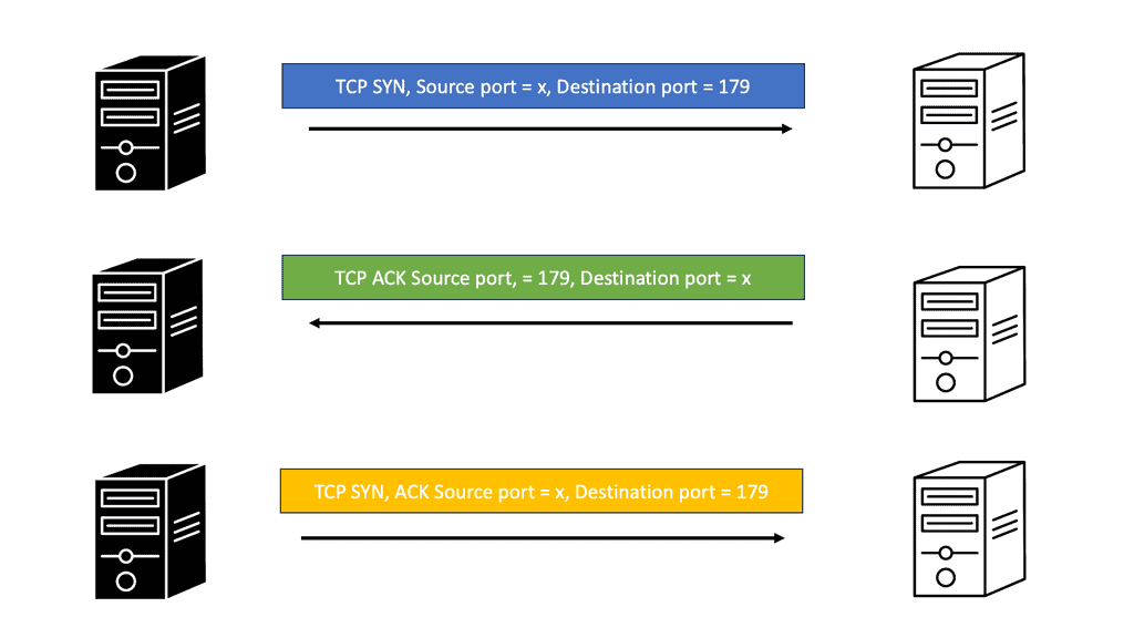
With Cloud CDN, your website gains global scalability. As your content is distributed across multiple edge locations worldwide, users from different geographical regions can access it quickly and efficiently. Cloud CDN automatically routes requests to the nearest edge location, ensuring that users experience minimal latency and optimal performance.

Traffic spikes can challenge websites, leading to slower load times and potential downtime. However, Cloud CDN is specifically built to handle high volumes of traffic. By caching your website’s content and distributing it across numerous edge locations, Cloud CDN can effectively manage sudden surges in traffic, ensuring that your website remains responsive and available to users.

WAN Design Considerations: Optimal Performance

What is Performance-Based Routing?

Performance-based routing is a dynamic technique that intelligently directs network traffic based on real-time performance metrics. Unlike traditional static routing, which relies on pre-configured paths, performance-based routing considers various factors, such as latency, bandwidth, and packet loss, to determine the optimal path for data transmission. By constantly monitoring network conditions, performance-based routing ensures traffic is routed through the most efficient path, enhancing performance and improving user experience.

Enhanced Network Performance: Performance-based routing can significantly improve network performance by automatically adapting to changing network conditions. By dynamically selecting the best path for data transmission, it minimizes latency, reduces packet loss, and maximizes available bandwidth. This leads to faster data transfer, quicker response times, and a smoother user experience.

Increased Reliability and Redundancy: One of the key advantages of performance-based routing is its ability to provide increased reliability and redundancy. Continuously monitoring network performance can quickly identify issues such as network congestion or link failures. In such cases, it can dynamically reroute traffic through alternate paths, ensuring uninterrupted connectivity and minimizing downtime.

Cost Optimization: Performance-based routing also offers cost optimization benefits. Intelligently distributing traffic across multiple paths enables better utilization of available network resources. This can result in reduced bandwidth costs and improved use of existing network infrastructure. Additionally, businesses can use their network budget more efficiently by avoiding congested or expensive links.

  • Bandwidth Allocation

To lay a strong foundation for an efficient WAN, careful bandwidth allocation is imperative. Determining the bandwidth requirements of different applications and network segments is crucial to avoid congestion and bottlenecks. By prioritizing critical traffic and implementing Quality of Service (QoS) techniques, organizations can ensure that bandwidth is allocated appropriately, guaranteeing optimal performance.

  • Network Topology

The choice of network topology greatly influences WAN performance. Whether it’s a hub-and-spoke, full mesh, or hybrid topology, understanding the unique requirements of the organization is essential. Each topology has its pros and cons, impacting factors such as scalability, latency, and fault tolerance. Assessing the specific needs of the network and aligning them with the appropriate topology is vital for achieving high-performance WAN connectivity.

  • Traffic Routing and Optimization

Efficient traffic routing and optimization mechanisms play a pivotal role in enhancing WAN performance. Implementing intelligent routing protocols, such as Border Gateway Protocol (BGP) or Open Shortest Path First (OSPF), ensures efficient data flow across the WAN. Additionally, employing traffic optimization techniques like WAN optimization controllers and caching mechanisms can significantly reduce latency and enhance overall network performance.

Understanding TCP Performance Parameters

TCP performance parameters govern the behavior of TCP connections. These parameters include congestion control algorithms, window size, Maximum Segment Size (MSS), and more. Each plays a crucial role in determining the efficiency and reliability of data transmission.

Congestion Control Algorithms: Congestion control algorithms, such as Reno, Cubic, and BBR, regulate the amount of data sent over a network to avoid congestion. They dynamically adjust the sending rate based on network conditions, ensuring fair sharing of network resources and preventing congestion collapse.

Window Size and Maximum Segment Size (MSS): The window size represents the amount of data that can be sent without receiving an acknowledgment from the receiver. A larger window size allows for faster data transmission but also increases the chances of congestion. On the other hand, the Maximum Segment Size (MSS) defines the maximum amount of data that can be sent in a single TCP segment. Optimizing these parameters can significantly improve network performance.

Selective Acknowledgment (SACK): Selective Acknowledgment (SACK) extends TCP that allows the receiver to acknowledge non-contiguous data blocks, reducing retransmissions and improving efficiency. By selectively acknowledging lost segments, SACK enhances TCP’s ability to recover from packet loss.

Understanding TCP MSS

In simple terms, TCP MSS refers to the maximum amount of data that can be sent in a single TCP segment. It is a parameter negotiated during the TCP handshake process and is typically determined by the underlying network’s Maximum Transmission Unit (MTU). Understanding the concept of TCP MSS is essential as it directly affects network performance and can have implications for various applications.

The significance of TCP MSS lies in its ability to prevent data packet fragmentation during transmission. By adhering to the maximum segment size, TCP ensures that packets are not divided into smaller fragments, reducing overhead and potential delays in reassembling them at the receiving end. This improves network efficiency and minimizes the chances of packet loss or retransmissions.

TCP MSS directly impacts network communications, especially when traversing networks with varying MTUs. Fragmentation may occur when a TCP segment encounters a network with a smaller MTU than the MSS. This can lead to increased latency, reduced throughput, and performance degradation. It is crucial to optimize TCP MSS to avoid such scenarios and maintain smooth network communications.

Optimizing TCP MSS involves ensuring that it is appropriately set to accommodate the underlying network’s MTU. This can be achieved by adjusting the end hosts’ MSS value or leveraging Path MTU Discovery (PMTUD) techniques to determine the optimal MSS for a given network path dynamically. By optimizing TCP MSS, network administrators can enhance performance, minimize fragmentation, and improve overall user experience.

DMVPN: At the WAN Edge

Understanding DMVPN:

DMVPN is a routing technique that allows for the creation of scalable and dynamic virtual private networks over the Internet. Unlike traditional VPN solutions, which rely on point-to-point connections, DMVPN utilizes a hub-and-spoke architecture, offering flexibility and ease of deployment. By leveraging multipoint GRE tunnels, DMVPN enables secure communication between remote sites, making it an ideal choice for organizations with geographically dispersed branches.

Benefits of DMVPN:

Enhanced Scalability: With DMVPN, network administrators can easily add or remove remote sites without complex manual configurations. This scalability allows businesses to adapt swiftly to changing requirements and effortlessly expand their network infrastructure.

Cost Efficiency: DMVPN uses existing internet connections to eliminate the need for expensive dedicated lines. This cost-effective approach ensures organizations can optimize their network budget without compromising security or performance.

Simplified Management: DMVPN simplifies network management by centralizing the configuration and control of VPN connections at the hub site. With routing protocols such as EIGRP or OSPF, network administrators can efficiently manage and monitor the entire network from a single location, ensuring seamless connectivity and minimizing downtime.

Security Considerations

While DMVPN provides a secure communication channel, proper security measures must be implemented to protect sensitive data. Encryption protocols such as IPsec can add an additional layer of security to VPN tunnels, safeguarding against potential threats.

Bandwidth Optimization

DMVPN employs NHRP (Next Hop Resolution Protocol) and IP multicast to optimize bandwidth utilization. These technologies help reduce unnecessary traffic and improve network performance, especially in bandwidth-constrained environments.

WAN Use Case: Exploring Single Hub Dual Cloud

Single hub dual cloud is an advanced variation of DMVPN that enhances network reliability and redundancy. It involves the deployment of two separate cloud infrastructures, each with its own set of internet service providers (ISPs), interconnected to a single hub. This setup ensures that even if one cloud or ISP experiences downtime, the network remains operational, maintaining seamless connectivity.

a) Enhanced Redundancy: Using two independent cloud infrastructures, single hub dual cloud provides built-in redundancy, minimizing the risk of service disruptions. This redundancy ensures that critical applications and services remain accessible even in the event of a cloud or ISP failure.

b) Improved Performance: Utilizing multiple clouds allows for load balancing and traffic optimization, improving network performance. A single-hub dual cloud distributes network traffic across the two clouds, preventing congestion and bottlenecks.

c) Simplified Maintenance: With a single hub dual cloud, network administrators can perform maintenance tasks on one cloud while the other remains operational. This ensures minimal downtime and allows for seamless updates and upgrades.

Understanding GETVPN

GETVPN, at its core, is a key-based encryption technology that provides secure and scalable communication within a network. Unlike traditional VPNs that rely on tunneling protocols, GETVPN operates at the network layer, encrypting and authenticating multicast traffic. By using a standard encryption key, GETVPN ensures confidentiality, integrity, and authentication for all group members.

GETVPN offers several key benefits that make it an attractive choice for organizations. Firstly, it enables secure communication over any IP network, making it versatile and adaptable to various infrastructures. Secondly, it provides end-to-end encryption, ensuring that data remains protected from unauthorized access throughout its journey. Additionally, GETVPN offers simplified key management, reducing the administrative burden and enhancing scalability.

Implementation and Deployment

Implementing GETVPN requires careful planning and configuration. Organizations must designate a Key Server (KS) responsible for managing key distribution and group membership. Group Members (GMs) receive the encryption keys from the KS and can decrypt the multicast traffic. By following best practices and considering network topology, organizations can deploy GETVPN effectively and seamlessly.

Example WAN Technology: VRFs

Understanding Virtual Routing and Forwarding

VRF is best described as isolating routing and forwarding tables, creating independent routing instances within a shared network infrastructure. Each VRF functions as a separate virtual router, with its routing table, routing protocols, and forwarding decisions. This segmentation enhances network security, scalability, and flexibility.

While VRF brings numerous benefits, it is crucial to consider certain factors when implementing it. Firstly, careful planning and design are essential to ensure proper VRF segmentation and avoid potential overlap or conflicts. Secondly, adequate network resources must be allocated to support the increased routing and forwarding tables associated with multiple VRFs. Lastly, thorough testing and validation are necessary to guarantee the desired functionality and performance of the VRF implementation.

Understanding Network Address Translation

NAT bridges private and public networks, enabling private IP addresses to communicate with the Internet. It involves translating IP addresses and ports, ensuring seamless data transfer across different networks. Let’s explore the fundamental concepts behind NAT and its significance in networking.

There are several types of NAT, each with unique characteristics and applications. We will examine the most common types: Static NAT, Dynamic NAT, and Port Address Translation (PAT). Understanding these variations will illuminate their specific use cases and advantages.

NAT offers numerous benefits for organizations and individuals alike. From conserving limited public IP addresses to enhancing network security, NAT plays a pivotal role in modern networking infrastructure. We will discuss these advantages in detail, showcasing how NAT has become integral to our connected world.

While Network Address Translation presents many advantages, it also has specific challenges. One such challenge is the potential impact on specific network protocols and applications that rely on untouched IP addresses. We will explore these considerations and discuss strategies to mitigate any possible issues that may arise.

WAN Design Considerations

Redundancy and High Availability:

Redundancy and high availability are vital considerations in WAN design to ensure uninterrupted connectivity. Implementing redundant links, multiple paths, and failover mechanisms can help mitigate the impact of network failures or outages. Redundancy also plays a crucial role in load balancing and optimizing network performance.

Diverse Connection Paths

One of the primary components of WAN redundancy is the establishment of diverse connection paths. This involves utilizing multiple carriers or network providers offering different physical transmission routes. By having diverse connection paths, businesses can reduce the risk of a complete network outage caused by a single point of failure.

Automatic Failover Mechanisms

Another crucial component is the implementation of automatic failover mechanisms. These mechanisms monitor the primary connection and instantly switch to the redundant connection if any issues or failures are detected. Automatic failover ensures minimal downtime and enables seamless transition without manual intervention.

Redundant Hardware and Equipment

Businesses must invest in redundant hardware and equipment to achieve adequate WAN redundancy. This includes redundant routers, switches, and other network devices. By having duplicate hardware, businesses can ensure that a failure in one device does not disrupt the entire network. Redundant hardware also facilitates faster recovery and minimizes the impact of failures.

Load Balancing and Traffic Optimization

WAN redundancy provides failover capabilities and enables load balancing and traffic optimization. Load balancing distributes network traffic across multiple connections, maximizing bandwidth utilization and preventing congestion. Traffic optimization algorithms intelligently route data through the most efficient paths, ensuring optimal performance and minimizing latency.

Example: DMVPN Single Hub Dual Cloud

Exploring the Single Hub Architecture

The single hub architecture in DMVPN involves establishing a central hub location that acts as a focal point for all site-to-site VPN connections. This hub is a central routing device, allowing seamless communication between various remote sites. By consolidating the VPN traffic at a single location, network administrators gain better control and visibility over the entire network.

One key advantage of DMVPN’s single hub architecture is the ability to connect to multiple cloud service providers simultaneously. This dual cloud connectivity enhances network resilience and allows organizations to distribute their workload across different cloud platforms. By leveraging this feature, businesses can ensure high availability, minimize latency, and optimize their cloud resources.

Implementing DMVPN with a single hub and dual cloud connectivity brings numerous benefits to organizations. It enables simplified network management, reduces operational costs, and enhances network scalability. However, it is crucial to consider factors such as security, bandwidth requirements, and cloud provider compatibility when designing and implementing this architecture.

WAN Design Considerations: Ensuring Security Characteristics

A secure WAN is the foundation of a resilient and protected network environment. It shields data, applications, and resources from unauthorized access, ensuring confidentiality, integrity, and availability. By comprehending the significance of WAN security, organizations can make informed decisions to fortify their networks.

  • Encryption and Data Protection

Encryption plays a pivotal role in safeguarding data transmitted across a WAN. Implementing robust encryption protocols, such as IPsec or SSL/TLS, can shield sensitive information from interception or tampering. Additionally, employing data protection mechanisms like data loss prevention (DLP) tools and access controls adds an extra layer of security.

  • Access Control and User Authentication

Controlling access to the WAN is essential to prevent unauthorized entry and potential security breaches. Implementing strong user authentication mechanisms, such as two-factor authentication (2FA) or multi-factor authentication (MFA), ensures that only authorized individuals can access the network. Furthermore, incorporating granular access control policies helps restrict network access based on user roles and privileges.

  • Network Segmentation and Firewall Placement

Proper network segmentation is crucial to limit the potential impact of security incidents. Dividing the network into secure segments or Virtual Local Area Networks (VLANs) helps contain breaches and restricts lateral movement. Additionally, strategically placing firewalls at entry and exit points of the WAN provides an added layer of protection by inspecting and filtering network traffic.

  • Monitoring and Threat Detection

Continuous monitoring of the WAN is paramount to identify potential security threats and respond swiftly. Implementing robust intrusion detection and prevention systems (IDS/IPS) enables real-time threat detection, while network traffic analysis tools provide insights into anomalous behavior. By promptly detecting and mitigating security incidents, organizations can ensure the integrity of their WAN.

Google Cloud Security

Understanding Google Compute Resources

Google Compute Engine (GCE) is a cloud-based infrastructure service that enables businesses to deploy and run virtual machines (VMs) on Google’s infrastructure. GCE offers scalability, flexibility, and reliability, making it an ideal choice for various workloads. However, with the increasing number of cyber attacks targeting cloud infrastructure, it is crucial to implement robust security measures to protect these resources.

The Power of FortiGate

FortiGate is a next-generation firewall (NGFW) solution offered by Fortinet, a leading provider of cybersecurity solutions. It is designed to deliver advanced threat protection, high-performance inspection, and granular visibility across networks. FortiGate brings a wide range of security features to the table, including intrusion prevention, antivirus, application control, web filtering, and more.

Enhanced Threat Prevention: FortiGate provides advanced threat intelligence and real-time protection against known and emerging threats. Its advanced security features, such as sandboxing and behavior-based analysis, ensure that malicious activities are detected and prevented before they can cause damage.

High Performance: FortiGate offers high-speed inspection and low latency, ensuring that security doesn’t compromise the performance of Google Compute resources. With FortiGate, organizations can achieve optimal security without sacrificing speed or productivity.

Simplified Management: FortiGate allows centralized management of security policies and configurations, making it easier to monitor and control security across Google Compute environments. Its intuitive user interface and robust management tools simplify the task of managing security policies and responding to threats.

WAN – Quality of Service (QoS):

Different types of traffic, such as voice, video, and data, coexist in a WAN. Implementing quality of service (QoS) mechanisms allows prioritizing and allocating network resources based on the specific requirements of each traffic type. This ensures critical applications receive the bandwidth and latency to perform optimally.

Identifying QoS Requirements

Every organization has unique requirements regarding WAN QoS. It is essential to identify these requirements to tailor the QoS implementation accordingly. Key factors include application sensitivity, traffic volume, and network topology. By thoroughly analyzing these factors, organizations can determine the appropriate QoS policies and configurations that align with their needs.

Bandwidth Allocation and Traffic Prioritization

Bandwidth allocation plays a vital role in QoS implementation. Different applications have varying bandwidth requirements, and allocating bandwidth based on priority is essential. By categorizing traffic into different classes and assigning appropriate priorities, organizations can ensure that critical applications receive sufficient bandwidth while non-essential traffic is regulated to prevent congestion.

QoS Mechanisms for Latency and Packet Loss

Latency and packet loss can significantly impact application performance in WAN environments. To mitigate these issues, QoS mechanisms such as traffic shaping, traffic policing, and queuing techniques come into play. Traffic shaping helps regulate traffic flow, ensuring it adheres to predefined limits. Traffic policing, on the other hand, monitors and controls the rate of incoming and outgoing traffic. Proper queuing techniques ensure that real-time and mission-critical traffic is prioritized, minimizing latency and packet loss.

Network Monitoring and Optimization

Implementing QoS is not a one-time task; it requires continuous monitoring and optimization. Network monitoring tools provide valuable insights into traffic patterns, performance bottlenecks, and QoS effectiveness. With this data, organizations can fine-tune their QoS configurations, adjust bandwidth allocation, and optimize traffic management to meet evolving requirements.

Related: Before you proceed, you may find the following posts helpful:

  1. SD-WAN Overlay
  2. WAN Virtualization
  3. Software-Defined Perimeter Solutions
  4. IDS IPS Azure
  5. SD WAN Security
  6. Data Center Design Guide

WAN Design Considerations

Defining the WAN edge

Wide Area Network (WAN) edge is a term used to describe the outermost part of a vast area network. It is the point at which the network connects to the public Internet or private networks, such as a local area network (LAN). The WAN edge is typically comprised of customer premises equipment (CPE) such as routers, firewalls, and other types of hardware. This hardware connects to other networks, such as the Internet, and provides a secure connection.

The WAN Edge also includes software such as network management systems, which help maintain and monitor the network. Standard network solutions at the WAN edge are SD-WAN and DMVPN. In this post, we will address an SD-WAN design guide. For details on DMVPN and its phases, including DMVPN phase 3, visit the links.

An Enterprise WAN edge consists of several functional blocks, including Enterprise WAN Edge Distribution and Aggregation. The WAN Edge Distribution provides connectivity to the core network and acts as an integration point for any edge service, such as IPS and application optimization. The WAN Edge Aggregation is a line of defense that performs aggregation and VPN termination. The following post focuses on integrating IPS for the WAN Edge Distribution-functional block.

Back to Basic with the WAN Edge

Concept of the wide-area network (WAN)

A WAN connects your offices, data centers, applications, and storage. It is called a wide-area network because it spans outside a single building or large campus to enclose numerous locations across a specific geographic area. Since WAN is an extensive network, the data transmission speed is lower than that of other networks. An is connects you to the outside world; it’s an integral part of the infrastructure to have integrated security. You could say the WAN is the first line of defense.

Topologies of WAN (Wide Area Network)

  1. Firstly, we have a point-to-point topology. A point-to-point topology utilizes a point-to-point circuit between two endpoints.
  2. We also have a hub-and-spoke topology. 
  3. Full mesh topology. 
  4. Finally, a dual-homed topology.

Concept of SD-WAN

SD-WAN (Software-Defined Wide Area Network) technology enables businesses to create a secure, reliable, and cost-effective WAN (Wide Area Network) connection. SD-WAN can provide enterprises various benefits, including increased security, improved performance, and cost savings. SD-WAN provides a secure tunnel over the public internet, eliminating the need for expensive networking hardware and services. Instead, SD-WAN relies on software to direct traffic flows and establish secure site connections. This allows businesses to optimize network traffic and save money on their infrastructure.

SD WAN traffic steering
Diagram: SD-WAN traffic steering. Source Cisco.

SD-WAN Design Guide

An SD-WAN design guide is a practice that focuses on designing and implementing software-defined wide-area network (SD-WAN) solutions. SD-WAN Design requires a thorough understanding of the underlying network architecture, traffic patterns, and applications. It also requires an understanding of how the different components of the network interact and how that interaction affects application performance.

To successfully design an SD-WAN solution, an organization must first determine the business goals and objectives for the network. This will help define the network’s requirements, such as bandwidth, latency, reliability, and security. The next step is determining the network topology: the network structure and how the components connect.

Once the topology is determined, the organization must decide on the hardware and software components to use in the network. This includes selecting suitable routers, switches, firewalls, and SD-WAN controllers. The hardware must also be configured correctly to ensure optimal performance.

Once the components are selected and configured, the organization can design the SD-WAN solution. This involves creating virtual overlays, which are the connections between the different parts of the network. The organization must also develop policies and rules to govern the network traffic.

Cisco SD WAN Overlay
Diagram: Cisco SD WAN overlay. Source Network Academy

Key WAN Design Considerations

  1. Dynamic multi-pathing. Being able to load-balance traffic over multiple WAN links isn’t new.
  2. Policy. There is a broad movement to implement a policy-based approach to all aspects of IT, including networking.
  3. Visibility.
  4. Integration. The ability to integrate security such as the IPS

Google SD-WAN Cloud Hub

SD-WAN Cloud Hub takes the potential of SD-WAN and Google Cloud to the next level. By combining the agility and intelligence of SD-WAN with the scalability and reliability of Google Cloud, organizations can achieve optimized connectivity and seamless integration with cloud-based services.

WAN Security – Intrusion Prevention System

An IPS uses signature-based detection, anomaly-based detection, and protocol analysis to detect malicious activities. Signature-based detection involves comparing the network traffic against a known list of malicious activities. In contrast, anomaly-based detection identifies activities that deviate from the expected behavior of the network. Finally, protocol analysis detects malicious activities by analyzing the network protocol and the packets exchanged.

An IPS includes network access control, virtual patching, and application control. Network access control restricts access to the network by blocking malicious connections and allowing only trusted relationships. Virtual patching detects any vulnerability in the system and provides a temporary fix until the patch is released. Finally, application control restricts the applications users can access to ensure that only authorized applications are used.

The following design guide illustrates EtherChannel Load Balancing ( ECLB ) for Intrusion Prevention System ( IPS ) high availability and traffic symmetry through Interior Gateway Protocol ( IGP ) metric manipulation. Symmetric traffic ensures the IPS system has visibility of the entire traffic path. However, IPS can lose visibility into traffic flows with asymmetrical data paths. 

IPS key points

  • Two VLANs on each switch logically insert IPS into the data path. VLANs 9 and 11 are the outside VLANs that face Wide Area Networks ( WAN ), and VLANs 10 and 12 are the inside VLANs that meet the protected Core.
  • VLAN pairing on each IPS bridges traffic back to the switch across its VLANs.
wan design considerations
Diagram: WAN design considerations.
  • Etherchannel Load balancing ( ECLB ) allows the split of flows over different physical paths to and from the Intrusion Prevention System ( IPS ). It is recommended that load balance on flows be used as opposed to individual packets.
  •  ECLB performs a hash on the flow’s source and destination IP address to determine what physical port a flow should take. It’s a form of load splitting as opposed to load balancing.
  • IPS does not maintain a state if a sensor goes down. TCP flow will be reset and forced through a different IPS appliance.
  • Layer 3 routed point-to-point links implemented between switches and ASR edge routers. Interior Gateway Protocol ( IGP ) path costs are manipulated to influence traffic to and from each ASR. We are ensuring traffic symmetry.
what is wan edge
Diagram: What is wan edge traffic flow
  • OSPF deployed IGP; the costs are manipulated per interface to influence traffic flow. OSPF calculates costs in the outbound direction. Selection EIGRP as the IGP, destinations are chosen based on minimum path bandwidth and accumulative delay.
  • All interfaces between WAN distribution and WAN edge, including the outside VLANs ( 9 and 11 ), are placed in a Virtual Routing and Forwarding ( VRF ) instance. VRFs force all traffic between the WAN edge and the internal Core via an IPS device.

WAN Edge Considerations with the IPS

A recommended design would centralize the IPS in a hub-and-spokes system where all branch office traffic is forced through the WAN edge. In addition, a distributed IPS model should be used if local branch sites use split tunneling for local internet access.

The IPS should receive unmodified and clear text traffic. To ensure this, integrate the IPS inside the WAN edge after any VPN termination or application optimization techniques. When using route manipulation to provide traffic symmetry, a single path ( via one ASR ) should have sufficient bandwidth to accommodate the total traffic capacity of both links.

ECLB performs hashing on the source and destination address, not the flow’s bandwidth. If there are high traffic volumes between a single source and destination, all traffic passes through a single IPS.

Closing Points: WAN Design Consideration

Before diving into the technical details, it’s vital to understand the specific requirements of your network. Consider the number of users, the types of applications they’ll be accessing, and the amount of data transfer involved. Different applications, such as VoIP, video conferencing, and data-heavy software, require varying levels of bandwidth and latency. By mapping out these needs, you can tailor your WAN design to provide optimal performance.

The technology you choose to implement your WAN plays a significant role in its efficiency. Traditional options like MPLS (Multiprotocol Label Switching) offer reliability and quality of service, but newer technologies such as SD-WAN (Software-Defined Wide Area Network) provide greater flexibility and cost savings. SD-WAN allows for centralized control, making it easier to manage traffic and adjust to changing demands. Evaluate the pros and cons of each option to determine the best fit for your organization.

Security is a paramount concern in WAN design. With data traversing various networks, implementing robust security measures is essential. Consider integrating features like encryption, firewalls, and intrusion detection systems. Additionally, adopt a zero-trust approach by authenticating every device and user accessing the network. Regularly update your security protocols to defend against evolving threats.

Optimizing bandwidth and managing latency are critical for ensuring smooth network performance. Implement traffic prioritization to ensure that mission-critical applications receive the necessary resources. Consider employing WAN optimization techniques, such as data compression and caching, to enhance speed and reduce latency. Regularly monitor network performance to identify and rectify any bottlenecks.

Summary: WAN Design Considerations

In today’s interconnected world, a well-designed Wide Area Network (WAN) is essential for businesses to ensure seamless communication, data transfer, and collaboration across multiple locations. Building an efficient WAN involves considering various factors that impact network performance, security, scalability, and cost-effectiveness. In this blog post, we delved into the critical considerations for WAN design, providing insights and guidance for constructing a robust network infrastructure.

Bandwidth Requirements

When designing a WAN, understanding the bandwidth requirements is crucial. Analyzing the volume of data traffic, the types of applications being used, and the number of users accessing the network are essential factors to consider. Organizations can ensure optimal network performance and prevent potential bottlenecks by accurately assessing bandwidth needs.

Network Topology

Choosing the correct network topology is another critical aspect of WAN design. Whether it’s a star, mesh, ring, or hybrid topology, each has its advantages and disadvantages. Factors such as scalability, redundancy, and ease of management must be considered to determine the most suitable topology for the organization’s specific requirements.

Security Measures

Securing the WAN infrastructure is paramount to protect sensitive data and prevent unauthorized access. Implementing robust encryption protocols, firewalls, intrusion detection systems, and virtual private networks (VPNs) are vital considerations. Additionally, regular security audits, access controls, and employee training on best security practices are essential to maintain a secure WAN environment.

Quality of Service (QoS)

Maintaining consistent and reliable network performance is crucial for organizations relying on real-time applications such as VoIP, video conferencing, or cloud-based services. Implementing Quality of Service (QoS) mechanisms enables prioritization of critical traffic, ensuring a smooth and uninterrupted user experience. Properly configuring QoS policies helps allocate bandwidth effectively and manage network congestion.

Conclusion:

Designing a robust WAN requires a comprehensive understanding of an organization’s unique requirements, considering factors such as bandwidth requirements, network topology, security measures, and Quality of Service (QoS). By carefully evaluating these considerations, organizations can build a resilient and high-performing WAN infrastructure that supports their business objectives and facilitates seamless communication and collaboration across multiple locations.

virtual device context

Virtual Device Context

Virtual Device Context

In today's rapidly evolving technological landscape, virtual device context (VDC) has emerged as a powerful tool for network management and optimization. By providing virtualized network environments within a physical network infrastructure, VDC enables organizations to enhance flexibility, scalability, and security. In this blog post, we will explore the concept of VDC, its benefits, and its real-world applications.

Virtual device context, in essence, involves the partitioning of a physical network device into multiple logical devices. Each VDC operates independently and provides a dedicated set of resources, such as routing tables, VLANs, and interfaces. This segregation ensures that different network functions or departments can operate within their isolated environments, preventing interference and enhancing network performance.

Enhanced Flexibility: By leveraging VDC, organizations can dynamically allocate resources to different network segments based on their requirements. This flexibility allows for efficient resource utilization and the ability to respond to changing network demands swiftly.

Improved Scalability: VDC enables horizontal scaling by effectively dividing a single physical device into multiple logical instances. This scalability empowers organizations to expand their network capacity without the need for significant hardware investments.

Enhanced Security: Through VDC, organizations can establish isolated network environments, ensuring that sensitive data and critical network functions are protected from unauthorized access. This enhanced security posture minimizes the risk of data breaches and network vulnerabilities.

Data Centers: Modern data centers are complex ecosystems with diverse network requirements. VDC allows for the logical separation of various departments, applications, or tenants within a single data center infrastructure. This isolation ensures efficient resource allocation, optimized performance, and enhanced security.

Service Providers: Virtual device context finds extensive applications in service provider networks. By utilizing VDC, service providers can offer multi-tenant services to their customers while maintaining strict segregation between each tenant's network environment. This isolation provides enhanced security and allows for efficient resource allocation per customer.

Virtual device context has revolutionized network management by offering enhanced flexibility, scalability, and security. Its ability to partition a physical network device into multiple logical instances opens up new avenues for optimizing network infrastructure and meeting evolving business requirements. By embracing VDC, organizations can take a significant step towards building robust and future-ready networks.

Highlights: Virtual Device Context

Virtual Device Contexts (VDC) let you carve out numerous virtual switches from a single physical Nexus switch. Each VDC is logically separated from every other VDC on a switch. Thus, just like physical switches to trunk or route traffic between them, physical interfaces and cabling are required to attach two or more VDCs before this can happen.

The number of VDCs that can be created depends upon the version of NX-OS, the Supervisor model, and the license installed. For example, the newer Supervisor 2E can support up to eight VDCs and one Admin VDC.

VDC utilizes the concept of virtualization to create isolated network environments within a single physical switch. By dividing the switch into multiple logical switches, network administrators can allocate resources, such as CPU, memory, and interfaces, to each VDC independently. This enables them to manage and control multiple networks within a single device with distinct configurations.

**Benefits of Virtual Device Context**

1. Enhanced Network Performance: With VDC, network administrators can allocate dedicated resources to each virtual device, ensuring optimal performance. By isolating traffic, VDC prevents any device from monopolizing network resources, improving overall network performance.

2. Increased Network Efficiency: VDC allows administrators to run multiple applications or services on separate virtual devices, eliminating potential conflicts. This segregation enhances network efficiency by minimizing downtime and enabling better resource utilization.

3. Simplified Network Management: By consolidating multiple logical devices into a single physical switch, VDC simplifies network management. Administrators can independently configure and monitor each VDC, reducing complexity and streamlining operations.

4. Cost Savings: Virtual Device Context eliminates the need to purchase and manage multiple physical switches, resulting in organization cost savings. By leveraging VDC, businesses can achieve network segmentation and isolation while optimizing resource utilization, thus reducing capital and operational expenditure.

**Use Cases of Virtual Device Context**

1. Data Centers: VDC is commonly used in data centers to create virtual networks for different departments or tenants, ensuring secure and isolated environments.

2. Service Providers: VDC enables providers to offer virtualized network services to their customers, providing greater flexibility and scalability.

3. Testing and Development Environments: VDC allows organizations to create virtual network environments for testing and development purposes, enabling efficient resource allocation and isolation.

Cisco NX-OS and VDC

Cisco NX-OS provides fault isolation, management isolation, address allocation isolation, service differentiation domains, and adaptive resource management through VDCs. An instance of a VDC can be managed independently within a physical device, and users connected to it perceive it as a unique device. VDCs run as logical entities within physical devices, maintain their configurations, run their software processes, and are managed by a different administrator.

Kernel and Infrastructure Layer

The Cisco NX-OS software is built on a kernel and infrastructure layer. On a physical device, the kernel supports all processes and virtual disks. These TCAMs serve as interfaces between higher-level processes and the hardware resources of the physical device. Scalability of Cisco NX-OS software can be achieved by avoiding duplication of systems management processes at this layer (see figure below).

It is also the infrastructure that enforces isolation across VDCs. When a fault occurs within a VDC, it does not impact services in other VDCs. Thus, software faults are limited, and device reliability is greatly enhanced.

Nonvirtualized services may have only one instance per VDC and the infrastructure layer. These services create VDCs, move resources between VDCs, and monitor protocol services within a VDC.

Example Segmentation Technology – VRF

Understanding VRF

VRF, at its core, separates the routing instances within a router, enabling the creation of isolated routing domains. Each VRF instance maintains its routing table, forwarding table, and associated network interfaces. This logical separation allows for the creation of multiple independent virtual networks within a physical infrastructure without the need for additional hardware.

One of the key advantages of VRF is its ability to provide network segmentation. By creating separate VRF instances, organizations can isolate different departments, customers, or applications within their network infrastructure. This isolation enhances security by preventing unauthorized access between virtual networks and enables fine-grained control over routing policies.

Use Cases for VRF

VRF finds wide application in various scenarios. In large enterprises, it can be used to segregate network traffic between different departments, ensuring efficient resource utilization and minimizing the risk of data breaches. Internet Service Providers (ISPs) leverage VRF to provide their customers virtual private network (VPN) services, enabling secure and private communication over shared infrastructure. VRF is also widely used in multi-tenant environments, such as data centers, allowing multiple customers to coexist on the same physical network infrastructure while maintaining isolation and security.

Example: Cisco Nexus Switches

Virtual Device Contexts (VDC) allow you to carve or divide out multiple virtual switches from a single physical Nexus switch. The number of VDCs that can be created depends upon the version of NX-OS, the Supervisor model, and the license installed.

Inter-VDC communication is only via external interfaces; there is no internal switch. As a result, VDCs offer several benefits, such as a separate partition between different groups or organizations while using only a single switch. With device context, there are several virtual device context design options.

Example: Cisco ASA 5500 Series

Multiple approaches exist for firewall and load-balancing services in the data path. Design options exist for a Dedicated External Chassis ( Catalyst 6500 VSS ) with service modules inserted within the chassis or using dedicated External Appliances ( Cisco ASA 5500 Series Next-Generation Firewall).

With both modes, run the services in either “routed” or “transparent” modes. Routed mode creates separate routing domains between the server farm subnet and the services layer. On the other hand, Transparent Mode extends the routing domain down to the server farm layer.

Before you proceed, you may find the following posts helpful:

  1. Context Firewall
  2. Virtual Data Center Design
  3. ASA Failover
  4. Network Stretch
  5. OpenShift Security Best Practices

Virtual Device Context

VDC Design

The virtual Device Context ( VDC ) feature on the Nexus 7000 series is used for another type of virtualization. The concept of VDC design takes a single Nexus 7000 series and divides it into independent devices. In this example, the second independent device creates an additional aggregation layer.

Now, the data center has two-aggregation layers, the Primary Aggregation layer and the Sub-Aggregation layer. The services layer is sandwiched between the two-aggregation VDC blocks ( primary and sub-aggregation layer ), creating a concept known as the “Virtual Device Context Sandwich Model.”

virtual device context
Diagram: Virtual Device Context (VDC)

Now, there are two options for access layer connections. Some access layer switches can attach to the new sub-aggregation VDC. Other functional blocks not requiring services can be directly connected to the primary aggregation layer ( top VDC ), bypassing the service function. The central role of the primary aggregation layer is to provide Layer 3 forwarding from the services layer to the other functional blocks of the network. Small sites could collapse the core in the primary aggregation VDC.

Device context validated design.

The design is validated with the Firewall Service Module ( FWSM ) running in transparent mode and the ACE module running in routed mode. The two-aggregation layers are direct IP routing peers and configurations with VLANs, Virtual Routing and Forwarding ( VRFs ), Virtual Device Contexts ( VDC ), and Virtual Contexts. Within each VDC, VLANs map to VRFs, and VRFs can direct independent traffic through multiple virtual contexts on the service devices. If IP multicast is not required, the sub-aggregation VDC can have static pointing to a shared Hot Standby Router Protocol ( HSRP ) address on the primary aggregation VDC. 

Benefits of VDCs

  1. Inserting separate aggregation layers using the VDC approach provides much better isolation than previous designs using VLAN and VRF on a single switch.
  2. It also offers much better security. Instead of separating VLANs and VRFs on the same switch, the VDC concept creates separate virtual switches with their physical ports.
  3. The sub-aggregation layer is separate from the primary aggregation layer. You need to connect them directly to route from one VDC to another. It’s as if they are separate physical devices.

Drawback of VDCs

  1. The service chassis must have separate physical interfaces to each VDC layer. Additional interfaces must be provisioned for the inter-switch link between VDCs. Compared to the traditional method that is extended by adding VLANs on a trunk port.

Closing Points on Virtual Device Context (VDC)

VDC technology enables the division of a physical switch into distinct virtual switches, each with its own set of resources and configurations. This partitioning is akin to server virtualization, where a single physical machine runs multiple virtual servers. In the context of VDC, each virtual switch can be managed separately, allowing administrators to tailor network policies, security settings, and access controls to specific needs without interfering with other virtual switches on the same hardware.

The adoption of VDC offers a myriad of benefits. Firstly, it enhances resource utilization by allowing a single switch to support multiple network environments, reducing the need for additional hardware. This not only lowers capital expenditure but also streamlines network management. Additionally, VDC promotes greater security and fault isolation. By segregating network environments, organizations can minimize the risk of cross-contamination and ensure that failures in one virtual switch do not impact others. This isolation is crucial in multitenant environments where different users or departments share the same physical infrastructure.

VDC technology is particularly beneficial in environments requiring high levels of customization and control. For instance, in data centers, VDC can be used to separate production, development, and testing environments, each with unique configurations and security protocols. Similarly, service providers can use VDC to offer tailored network solutions to clients, providing each with a dedicated virtual switch. This flexibility makes it possible to deliver personalized services while maintaining operational efficiency.

While VDC offers significant advantages, there are challenges to consider. Implementing VDC requires a deep understanding of network architecture and careful planning to ensure optimal configuration and performance. Administrators must also be mindful of resource allocation, as the physical limitations of the hardware can impact the number of VDCs that can be effectively supported. Additionally, ongoing management and monitoring are crucial to maintain the integrity and efficiency of the virtual environments.

Summary: Virtual Device Context

In this digital age, the concept of virtual device context has emerged as a revolutionary tool in technology. With its ability to enhance performance, improve security, and streamline operations, virtual device context has become a game-changer for many organizations. In this blog post, we delved into the intricacies of the virtual device context, its benefits, and how it transforms how we interact with technology.

Understanding Virtual Device Context

Virtual device context, often abbreviated as VDC, refers to the virtualization technique that allows partitioning a physical device into multiple logical devices. Each logical device, or virtual device context, operates independently with its dedicated resources, such as CPU, memory, and interfaces. This virtualization enables the consolidation of multiple devices into a single physical infrastructure, leading to significant cost savings and operational efficiency.

The Benefits of Virtual Device Context

Enhanced Performance:

Organizations can ensure optimal performance for their applications and services by isolating resources for each virtual device context. This isolation prevents resource contention and efficiently utilizes available resources, improving overall performance.

Improved Security:

Virtual device context provides a robust security framework by isolating network traffic and preventing unauthorized access between different contexts. This isolation reduces the attack surface and enhances the overall security posture of the network infrastructure.

Simplified Management:

Network administrators can manage multiple logical devices as separate physical devices in a virtual device context. This simplifies the management and configuration tasks, allowing for easier network infrastructure provisioning, monitoring, and troubleshooting.

Use Cases of Virtual Device Context

Data Centers:

Virtual device context finds extensive use in data centers, enabling the consolidation of network devices and simplifying the management of complex infrastructures. It allows for efficient resource allocation, seamless scalability, and improved agility in deploying new services.

Service Providers:

Service providers leverage virtual device context to offer multi-tenancy services to their customers. Service providers can ensure isolation, security, and customized service offerings by creating separate virtual device contexts for each customer.

Conclusion:

Virtual device context is a powerful technology that has transformed how we design, manage, and operate network infrastructures. Its benefits, including enhanced performance, improved security, and simplified management, make it a valuable tool for organizations across various industries. As technology continues to evolve, virtual device context will undoubtedly play a crucial role in shaping the future of networking.

data center design

Virtual Data Center Design

Virtual Data Center Design

Virtual data centers are a virtualized infrastructure that emulates the functions of a physical data center. By leveraging virtualization technologies, these environments provide a flexible and agile foundation for businesses to house their IT infrastructure. They allow for the consolidation of resources, improved scalability, and efficient resource allocation.

A well-designed virtual data center comprises several key components. These include virtual servers, storage systems, networking infrastructure, and management software. Each component plays a vital role in ensuring optimal performance, security, and resource utilization.

When embarking on virtual data center design, certain considerations must be taken into account. These include workload analysis, capacity planning, network architecture, security measures, and disaster recovery strategies. By meticulously planning and designing each aspect, organizations can create a robust and resilient virtual data center.

To maximize efficiency and performance, it is crucial to follow best practices in virtual data center design. These practices include implementing proper resource allocation, leveraging automation and orchestration tools, adopting a scalable architecture, regularly monitoring and optimizing performance, and ensuring adequate security measures.

Virtual data center design offers several tangible benefits. By consolidating resources and optimizing workloads, organizations can achieve higher performance levels. Additionally, virtual data centers enable efficient utilization of hardware, reducing energy consumption and overall costs.

Highlights: Virtual Data Center Design

Understanding Virtual Data Centers

Virtual data centers, also known as VDCs, are a cloud-based infrastructure that allows businesses to store, manage, and process their data in a virtual environment. Unlike traditional data centers, which require physical hardware and dedicated spaces, VDCs leverage virtualization technologies to create a flexible and scalable solution.

At the heart of any virtual data center are its fundamental components. These include virtual machines, storage systems, networking, and management tools. Virtual machines act as the primary workhorses, running applications and services that were once confined to physical servers.

Storage systems in a VDC can dynamically allocate space, ensuring efficient data management. Networking, on the other hand, involves virtual switches and routers that facilitate seamless communication between virtual machines. Lastly, management tools offer administrators a centralized platform to monitor and optimize the VDC’s operations.

Key Considerations:

a) Virtual Machines (VMs): At the heart of virtual data center design are virtual machines. These software emulations of physical computers allow businesses to run multiple operating systems and applications on a single physical server, maximizing resource utilization.

b) Hypervisors: Hypervisors play a crucial role in virtual data center design by enabling the creation and management of VMs. They abstract the underlying hardware, allowing multiple VMs to run independently on the same physical server.

c) Software-defined Networking (SDN): SDN is a fundamental component of virtual data centers. It separates the network control plane from the underlying hardware, providing centralized management and programmability. This enables efficient network configuration, monitoring, and security across the virtual infrastructure.

Benefits of Virtual Data Center Design

a) Scalability: Virtual data centers offer unparalleled scalability, allowing businesses to easily add or remove resources as their needs evolve. This flexibility ensures optimal resource allocation and cost-effectiveness.

b) Cost Savings: By eliminating the need for physical hardware, virtual data centers significantly reduce upfront capital expenditures. Additionally, the ability to consolidate multiple VMs on a single server leads to reduced power consumption and maintenance costs.

c) Improved Disaster Recovery: Virtual data centers simplify disaster recovery procedures by enabling efficient backup, replication, and restoration of virtual machines. This enhances business continuity and minimizes downtime in case of system failures or outages.

Design Factors for Data Center Networks

When designing a data center network, network professionals must consider factors unrelated to their area of specialization. To avoid a network topology becoming a bottleneck for expansion, a design must consider the data center’s growth rate (expressed as the number of servers, switch ports, customers, or any other metric).

Data center network designs must also consider application bandwidth demand. Network professionals commonly use the oversubscription concept to translate such demand into more relatable units (such as ports or switch modules).

**Oversubscription**

Oversubscription occurs when multiple elements share a common resource and the allocated resources per user exceed the maximum value that each can use. Oversubscription refers to the amount of bandwidth switches can offer downstream devices at each layer in data center networks. The ratio of upstream server traffic oversubscription at the access layer switch would be 4:1, for example, if it has 32 10 Gigabit Ethernet server ports and eight uplink 10 Gigabit Ethernet interfaces.

**Sizing Failure Domains**

Oversubscription ratios must be tested and fine-tuned to determine the optimal network design for the application’s current and future needs.

Business-related decisions also influence the failure domain sizing of a data center network. The number of servers per IP subnet, access switch, or aggregation switch may not be solely determined by technical aspects if an organization cannot afford to lose multiple application environments simultaneously.

Data center network designs are affected by application resilience because they require perfect harmony between application and network availability mechanisms. An example would be:

  • An active server connection should be connected to an isolated network using redundant Ethernet interfaces.
  • An application server must be able to respond faster to a connection failure than the network.

Last, a data center network designer must be aware of situations where all factors should be prioritized since benefiting one aspect could be detrimental to another. Traditionally, the topology between the aggregation and access layers illustrates this situation.

### Scalability: Preparing for Growth

As data demands grow, so too must the networks that support them. Scalability is a crucial consideration in the design of data center networks. This involves planning for increased bandwidth, additional server capacity, and more extensive storage options. Implementing modular designs and utilizing technologies such as software-defined networking (SDN) can help data centers scale efficiently without significant disruptions.

### Reliability: Ensuring Consistent Uptime

Reliability is non-negotiable for data centers as any downtime can lead to significant losses. Network design must include redundant systems, failover mechanisms, and robust disaster recovery plans. Technologies such as network redundancy protocols and geographic distribution of data centers enhance reliability, ensuring that networks remain operational even in the face of unexpected failures.

### Security: Protecting Critical Data

In an era where data breaches are increasingly common, securing data center networks is paramount. Effective design involves implementing strong encryption protocols, firewalls, and intrusion detection systems. Regular security audits and employing a zero-trust architecture can further fortify networks against cyber threats, ensuring that sensitive data remains protected.

### Efficiency: Maximizing Performance with Minimal Resources

Efficiency in data center networks is about maximizing performance while minimizing resource consumption. This can be achieved through optimizing network traffic flow, utilizing energy-efficient hardware, and implementing advanced cooling solutions. Furthermore, automation tools can streamline operations, reduce human error, and optimize resource allocation.

Google Cloud Data Centers

### Unpacking Google Cloud’s Network Connectivity Center

Google Cloud’s Network Connectivity Center is a centralized platform tailored to help businesses manage their network connections efficiently. It offers a unified view of all network assets, enabling organizations to oversee their entire network infrastructure from a single console. With NCC, businesses can connect their on-premises resources with Google Cloud services, creating a seamless and integrated network experience. This tool simplifies the management of complex networks by providing robust monitoring, visibility, and control over network traffic.

### Key Features of Network Connectivity Center

One of the standout features of the Network Connectivity Center is its ability to facilitate hybrid and multi-cloud environments. By supporting a variety of connection types, including VPNs, interconnects, and third-party routers, NCC allows businesses to connect to Google Cloud’s global network efficiently. Its intelligent routing capabilities ensure optimal performance and reliability, reducing latency and improving user experience. Additionally, NCC’s policy-based management tools empower organizations to enforce security protocols and compliance measures across their network infrastructure.

### Benefits of Using Network Connectivity Center

The benefits of integrating Google Cloud’s Network Connectivity Center into your organization’s operations are manifold. For starters, NCC enhances network visibility, providing detailed insights into network performance and traffic patterns. This allows businesses to proactively identify and resolve issues before they impact operations. Moreover, NCC’s scalability ensures that as your organization grows, your network infrastructure can seamlessly expand to meet new demands. By consolidating network management tasks, NCC also reduces operational complexity and costs, allowing IT teams to focus on strategic initiatives.

### How to Get Started with Network Connectivity Center

Getting started with Google Cloud’s Network Connectivity Center is a straightforward process. Begin by assessing your current network infrastructure and identifying areas where NCC could add value. Next, set up your NCC environment by integrating your existing network connections and configuring routing policies to suit your organizational needs. Google Cloud provides comprehensive documentation and support to guide you through the setup process, ensuring a smooth transition and optimal utilization of NCC’s capabilities.

Network Connectivity Center

Google Machine Types Families

The Basics: What Are Machine Type Families?

Machine type families in Google Cloud refer to the categorization of virtual machines (VMs) based on their capabilities and intended use cases. Each family is designed to optimize performance for specific workloads, offering a balance between processing power, memory, and cost. Understanding these families is crucial for anyone looking to leverage Google Cloud’s infrastructure effectively.

### The Core Families: Standard, High-Memory, and High-CPU

Google Cloud’s machine type families are primarily divided into three core categories: Standard, High-Memory, and High-CPU.

– **Standard**: These are the most versatile and widely used machine types, providing a balanced ratio of CPU to memory. They are ideal for general-purpose applications, such as web servers and small databases.

– **High-Memory**: As the name suggests, these machines come with a higher memory capacity, making them suitable for memory-intensive applications like large databases and real-time data processing.

– **High-CPU**: These machines offer a higher CPU-to-memory ratio, perfect for compute-intensive workloads like batch processing and scientific simulations.

### Choosing the Right Family: Factors to Consider

Selecting the appropriate machine type family involves evaluating your specific workload requirements. Key factors to consider include:

– **Workload Characteristics**: Determine whether your application is CPU-bound, memory-bound, or requires a balanced approach.

– **Performance Requirements**: Assess the performance metrics that your application demands to ensure optimal operation.

– **Cost Efficiency**: Consider your budget constraints and balance them against the performance benefits of different machine types.

By carefully analyzing these factors, you can select a machine type family that aligns with your operational goals while optimizing cost and performance.

VM instance types

GKE & Virtual Data Centers

**The Power of Virtual Data Centers**

Virtual data centers have revolutionized the way businesses approach IT infrastructure. By leveraging cloud-based solutions, companies can dynamically allocate resources, reduce costs, and enhance scalability. GKE plays a pivotal role in this transformation by providing a streamlined, scalable, and secure environment for running containerized applications. It abstracts the underlying hardware, allowing businesses to focus on innovation rather than infrastructure management.

**Key Features of Google Kubernetes Engine**

GKE stands out with its comprehensive suite of features designed to enhance operational efficiency. One of its key strengths lies in its ability to auto-scale applications, ensuring optimal performance even under fluctuating loads. Additionally, GKE provides robust security features, including network policies and Google Cloud’s security foundation, to safeguard applications against potential threats. The seamless integration with other Google Cloud services further enhances its appeal, offering a cohesive ecosystem for developers and IT professionals.

**Implementing GKE: Best Practices**

When transitioning to GKE, adopting best practices can significantly enhance the deployment process. Businesses should start by thoroughly understanding their application architecture and resource requirements. It’s crucial to configure clusters to match these specifications to maximize performance and cost-efficiency. Regularly updating to the latest Kubernetes versions and leveraging built-in monitoring tools can also help maintain a secure and efficient environment.

Google Kubernetes Engine

Segmentation with NEGs

**Understanding Network Endpoint Groups**

Network Endpoint Groups are a collection of network endpoints that provide flexibility in how you manage your services. These endpoints can be various resources in Google Cloud, such as Compute Engine instances, Kubernetes Pods, or App Engine services. With NEGs, you have the capability to direct traffic to different backends based on demand, which helps in load balancing and improves the overall performance of your applications. NEGs are particularly beneficial when you need to manage services that are distributed across different regions, ensuring low latency and high availability.

**Enhancing Data Center Security**

Security is a paramount concern for any organization operating in the cloud. NEGs offer several features that can significantly enhance data center security. By using NEGs, you can create more granular security policies, allowing for precise control over which endpoints can be accessed and by whom. This helps in minimizing the attack surface and protecting sensitive data from unauthorized access. Additionally, NEGs facilitate the implementation of security patches and updates without disrupting the entire network, ensuring that your data center remains secure against emerging threats.

**Integrating NEGs with Google Cloud Services**

Google Cloud provides seamless integration with NEGs, making it easier for organizations to manage their cloud infrastructure. By leveraging Google Cloud’s robust ecosystem, NEGs can be integrated with various services such as Google Cloud Load Balancing, Cloud Armor, and Traffic Director. This integration enhances the capability of NEGs to efficiently route traffic, protect against DDoS attacks, and provide real-time traffic management. The synergy between NEGs and Google Cloud services ensures that your applications are not only secure but also highly performant and resilient.

**Best Practices for Implementing NEGs**

Implementing NEGs requires careful planning to maximize their benefits. It is essential to understand your network architecture and identify the endpoints that need to be grouped. Regularly monitor and audit your NEGs to ensure they are configured correctly and are providing the desired level of performance and security. Additionally, take advantage of Google Cloud’s monitoring tools to gain insights into traffic patterns and make data-driven decisions to optimize your network.

network endpoint groups

Managed Instance Groups

**Understanding Managed Instance Groups**

Managed Instance Groups are an essential feature for anyone looking to deploy scalable applications on Google Cloud. A MIG consists of identical VM instances, all configured from a common instance template. This uniformity ensures that any updates or changes applied to the template automatically propagate across all instances in the group, maintaining consistency. Additionally, MIGs offer auto-scaling capabilities, enabling the system to adjust the number of instances based on current workload demands. This flexibility means that businesses can optimize resource usage and potentially reduce costs.

**Benefits of Using MIGs on Google Cloud**

One of the primary advantages of using Managed Instance Groups on Google Cloud is their integration with other Google Cloud services, such as load balancing. By distributing incoming traffic across multiple instances, load balancers prevent any single instance from becoming overwhelmed, ensuring high availability and reliability. Moreover, MIGs support automated updates and self-healing features. In the event of an instance failure, a MIG automatically replaces or repairs the instance, minimizing downtime and maintaining application performance.

**Best Practices for Implementing MIGs**

To fully leverage the potential of Managed Instance Groups, it’s crucial to follow some best practices. Firstly, use instance templates to define VM configurations and ensure consistency across your instances. Regularly update these templates to incorporate security patches and performance improvements. Secondly, configure auto-scaling policies to match your application’s needs, allowing your infrastructure to dynamically adjust to changes in demand. Lastly, monitor your MIGs using Google Cloud’s monitoring tools to gain insights into performance and usage patterns, enabling you to make informed decisions about your infrastructure.

Managed Instance Group

### The Importance of Health Checks

Health checks are pivotal in maintaining an efficient cloud load balancing system. They are automated procedures that periodically check the status of your servers to ensure they are functioning correctly. By regularly monitoring server health, load balancers can quickly detect and route traffic away from any servers that are down or underperforming.

The primary objective of these checks is to ensure the availability and reliability of your application. If a server fails a health check, the load balancer will automatically redirect traffic to other servers that are performing optimally, thereby minimizing downtime and maintaining seamless user experience.

### How Google Cloud Implements Health Checks

Google Cloud offers robust health checking mechanisms within its load balancing services. These health checks are customizable, allowing you to define the parameters that determine the health of your servers. You can specify the protocol, port, and request path that the load balancer should use to check the health of each server.

Google Cloud’s health checks are designed to be highly efficient and scalable, ensuring that even as your application grows, the health checks remain effective. They provide detailed insights into the status of your servers, enabling you to make informed decisions about resource allocation and server management.

### Customizing Your Health Checks

One of the standout features of Google Cloud’s health checks is their flexibility. You can customize health checks based on the specific needs of your application. For example, you can set the frequency of checks, the timeout period, and the number of consecutive successful or failed checks required to mark a server as healthy or unhealthy.

This level of customization ensures that your load balancing strategy is tailored to your application’s unique requirements, providing optimal performance and reliability.

What is Cloud Armor?

Cloud Armor is a security service designed to protect your applications and services from a wide array of cyber threats. It acts as a shield, leveraging Google’s global infrastructure to deliver comprehensive security at scale. By implementing Cloud Armor, users can benefit from advanced threat detection, real-time traffic analysis, and customizable security policies tailored to their specific needs.

### Edge Security Policies: Your First Line of Defense

One of the standout features of Cloud Armor is its edge security policies. These policies allow you to define and enforce rules at the edge of Google’s network, ensuring that malicious traffic is blocked before it can reach your applications. By configuring edge security policies, you can protect against Distributed Denial of Service (DDoS) attacks, SQL injections, cross-site scripting (XSS), and other common threats. This proactive approach not only enhances security but also improves the performance and availability of your services.

### Customizing Your Cloud Armor Setup

Cloud Armor offers extensive customization options, enabling you to tailor security measures to your unique requirements. Users can create and apply custom rules based on IP addresses, geographic regions, and even specific request patterns. This flexibility ensures that you can adapt your defenses to match the evolving threat landscape, providing a dynamic and responsive security posture.

### Real-Time Monitoring and Reporting

Visibility is a crucial component of any security strategy. With Cloud Armor, you gain access to real-time monitoring and detailed reports on traffic patterns and security events. This transparency allows you to quickly identify and respond to potential threats, minimizing the risk of data breaches and service disruptions. The intuitive dashboard provides actionable insights, helping you to make informed decisions about your security policies and configurations.

Network Connectivity Center – Hub and Spoke

Google Cloud Network Tiers

Understanding Network Tiers

Network tiers, within the context of Google Cloud, refer to the different levels of network service quality and performance offered to users. Google Cloud provides two primary network tiers: Premium Tier and Standard Tier. Each tier comes with its own features, advantages, and pricing models.

The Premium Tier is designed for businesses that require high-speed, low-latency network connections to ensure optimal performance for their critical applications. With Premium Tier, enterprises can benefit from Google’s global fiber network, which spans across hundreds of points of presence worldwide. This tier offers enhanced reliability, improved routing efficiency, and reduced packet loss, making it an ideal choice for latency-sensitive workloads.

While the Premium Tier boasts top-notch performance, the Standard Tier provides a cost-effective option for businesses with less demanding network requirements. With the Standard Tier, users can still enjoy reliable connectivity and security features, but at a lower price point. This tier is suitable for applications that are less sensitive to network latency and can tolerate occasional performance variations.

Understanding VPC Networking

VPC Networking forms the foundation of any cloud infrastructure, enabling secure communication and resource isolation. In Google Cloud, a VPC is a virtual network that allows users to define and manage their own private space within the cloud environment. It provides a secure and scalable environment for deploying applications and services.

Google Cloud VPC offers a plethora of powerful features that enhance network management and security. From customizable IP addressing to robust firewall rules, VPC empowers users with granular control over their network configuration. Furthermore, the integration with other Google Cloud services, such as Cloud Load Balancing and Cloud VPN, opens up a world of possibilities for building highly available and resilient architectures.

Understanding HA VPN

HA VPN, or High Availability Virtual Private Network, is a robust networking solution Google Cloud offers. It allows organizations to establish secure connections between their on-premises networks and Google Cloud. HA VPN ensures continuous availability and redundancy, making it ideal for mission-critical applications and services.

Configuring HA VPN is straightforward and requires a few key steps. First, you must set up a Virtual Private Cloud (VPC) network in Google Cloud. Then, establish a Cloud VPN gateway and configure the necessary parameters, such as encryption methods and routing options. Finally, the on-premises VPN gateway must be configured to secure a Google Cloud connection.

HA VPN offers several benefits for businesses seeking secure and reliable networking solutions. Firstly, it provides high availability by establishing redundant connections with automatic failover capabilities. This ensures continuous access to critical resources, even during network failures. HA VPN offers enhanced security through strong encryption protocols, keeping data safe during transmission.

Gaining Efficiency

Deploying multiple tenants on a shared infrastructure is far more efficient than having single tenants per physical device. With a virtualized infrastructure, each tenant requires isolation from all other tenants sharing the same physical infrastructure.

For a data center network design, each network container requires path isolation, for example, 802.1Q on a shared Ethernet link between two switches, and device virtualization at the different network layers, for example, Cisco Application Control Engine ( ACE ) or Cisco Firewall Services Module ( FWSM ) virtual context. To implement independent paths with this type of data center design, you can create Virtual Routing Forwarding ( VRF ) per tenant and map the VRF to Layer 2 segments.

ACI fabric Details
Diagram: Cisco ACI fabric Details

Example: Virtual Data Center Design. Cisco.

More recently, the Cisco ACI network enabled segmentation based on logical security zones known as endpoint groups, where security constructs known as contracts are needed to communicate between endpoint groups. The Cisco ACI still uses VRFs, but they are used differently. Then, we have the Ansible Architecture, which can be used with Ansible variables to automate the deployment of the network and security constructs for the virtual data center. This brings consistency and will eliminate human error.

Understanding VPC Peering

VPC peering is a networking feature that allows you to connect VPC networks securely. It enables communication between resources in different VPCs, even across different projects or organizations within Google Cloud. Establishing peering connections can extend your network reach and allow seamless data transfer between VPCs.

To establish VPC peering in Google Cloud, follow a few simple steps. Firstly, identify the VPC networks you want to connect and ensure they do not have overlapping IP ranges. Then, the necessary peering connections are created, specifying the VPC networks involved. Once the peering connections are established, you can configure the routes to enable traffic flow between the VPCs. Google Cloud provides intuitive documentation and user-friendly interfaces to guide you through the setup process.

Before you proceed, you may find the following posts helpful for pre-information:

  1. Context Firewall
  2. Virtual Device Context
  3. Dynamic Workload Scaling
  4. ASA Failover
  5. Data Center Design Guide

Virtual Data Center Design

Numerous kinds of data centers and service models are available. Their category relies on several critical criteria. Such as whether one or many organizations own them, how they serve in the topology of other data centers, and what technologies they use for computing and storage. The main types of data centers include:

  • Enterprise data centers.
  • Managed services data centers.
  • Colocation data centers.
  • Cloud data centers.

You may build and maintain your own hybrid cloud data centers, lease space within colocation facilities, also known as colos, consume shared compute and storage services, or even use public cloud-based services.

Data center network design:

Example Segmentation Technology: VRF-lite

VRF information from a static or dynamic routing protocol is carried across hop-by-hop in a Layer 3 domain. Multiple VLANs in the Layer 2 domain are mapped to the corresponding VRF. VRF-lite is known as a hop-by-hop virtualization technique. The VRF instance logically separates tenants on the same physical device from a control plane perspective.

From a data plane perspective, the VLAN tags provide path isolation on each point-to-point Ethernet link that connects to the Layer 3 network. VRFs provide per-tenant routing and forwarding tables and ensure no server-server traffic is permitted unless explicitly allowed.

virtual and forwarding


Service Modules in Active/Active Mode

Multiple virtual contexts

The service layer must also be virtualized for tenant separation. The network services layer can be designed with a dedicated Data Center Services Node ( DSN ) or external physical appliances connected to the core/aggregation. The Cisco DSN data center design cases use virtual device contexts (VDC), virtual PortChannel (vPC), virtual switching system (VSS), VRF, and Cisco FWSM and Cisco ACE virtualization. 

This post will look at a DSN as a self-contained Catalyst 6500 series with ACE and firewall service modules. Virtualization at the services layer can be accomplished by creating separate contexts representing separate virtual devices. Multiple contexts are similar to having multiple standalone devices.

The Cisco Firewall Services Module ( FWSM ) provides a stateful inspection firewall service within a Catalyst 6500. It also offers separation through a virtual security context that can be transparently implemented as Layer 2 or as a router “hop” at Layer 3. The Cisco Application Control Engine ( ACE ) module also provides a range of load-balancing capabilities within a Catalyst 6500.

FWSM  features

 ACE features

Route health injection (RHI)

Route health injection (RHI)

Virtualization (context and resource allocation)

Virtualization (context and resource allocation)

Application inspection

Probes and server farm (service health checks and load-balancing predictor)

Redundancy (active-active context failover)

Stickiness (source IP and cookie insert)

Security and inspection

Load balancing (protocols, stickiness, FTP inspection, and SSL termination)

Network Address Translation (NAT) and Port Address Translation (PAT )

NAT

URL filtering

Redundancy (active-active context failover)

Layer 2 and 3 firewalling

Protocol inspection

You can offer high availability and efficient load distribution with a context design. The first FWSM and ACE are primary for the first context and standby for the second context. The second FWSM and ACE are primary for the second context and standby for the first context. Traffic is not automatically load-balanced equally across the contexts. Additional configuration steps are needed to configure different subnets in specific contexts.

Virtual Firewall and Load Balancing
Diagram: Virtual Firewall and Load Balancing

Compute separation

Traditional security architecture placed the security device in a central position, either in “transparent” or “routed” mode. Before communication could occur, all inter-host traffic had to be routed and filtered by the firewall device located at the aggregation layer. This works well in low-virtualized environments when there are few VMs. Still, a high-density model ( heavily virtualized environment ) forces us to reconsider firewall scale requirements at the aggregation layer.

It is recommended that virtual firewalls be deployed at the access layer to address the challenge of VM density and the ability to move VMs while keeping their security policies. This creates intra and inter-tenant zones and enables finer security granularity within single or multiple VLANs.

Application tier separation

The Network-Centric model relies on VLAN separation for three-tier application deployment for each tier. Each tier should have its VLAN in one VRF instance. If VLAN-to-VLAN communication needs to occur, traffic must be routed via a default gateway where security policies can enforce traffic inspection or redirection.

vShield ( vApp ) virtual appliance can inspect inter-VM traffic among ESX hosts, and layers 2,3,4, and 7 filters are supported. A drawback of this approach is that the FW can become a choke point. Compared to the Network-Centric model, the Server-Centric model uses separate VM vNICs and daisy chain tiers.

 Data center network design with Security Groups

The concept of Security groups replacing subnet-level firewalls with per-VM firewalls/ACLs. With this approach, there is no traffic tromboning or single choke points. It can be implemented with Cloudstack, OpenStack ( Neutron plugin extension ), and VMware vShield Edge. Security groups are elementary; you assign VMs and specify filters between groups. 

Security groups are suitable for policy-based filtering but don’t consider other functionality where data plane states are required for replay attacks. Security groups give you echo-based functionality, which should be good enough for current TCP stacks that have been hardened over the last 30 years. But if you require full stateful inspection and do not regularly patch your servers, then you should implement a complete stateful-based firewall.

Google Cloud Security

Understanding Google Compute Resources

Google Compute Engine (GCE) is a robust cloud computing platform that enables organizations to create and manage virtual machines (VMs) in the cloud. GCE offers scalable infrastructure, high-performance computing, and a wide array of services. However, with great power comes great responsibility, and it is essential to ensure the security of your GCE resources.

FortiGate is a next-generation firewall (NGFW) solution developed by Fortinet. It offers advanced security features such as intrusion prevention system (IPS), virtual private networking (VPN), antivirus, and web filtering. By deploying FortiGate in your Google Compute environment, you can establish a secure perimeter around your resources and mitigate potential cyber threats.

– Enhanced Threat Protection: FortiGate provides real-time threat intelligence, leveraging its extensive security services and threat feeds to detect and prevent malicious activities targeting your Google Compute resources.

– Simplified Management: FortiGate offers a centralized management interface, allowing you to configure and monitor security policies across multiple instances of Google Compute Engine effortlessly.

– High Performance: FortiGate is designed to handle high traffic volumes while maintaining low latency, ensuring that your Google Compute resources can operate at optimal speeds without compromising security.

Summary: Virtual Data Center Design

In today’s digital age, data management and storage have become critical for businesses and organizations of all sizes. Traditional data centers have long been the go-to solution, but with technological advancements, virtual data centers have emerged as game-changers. In this blog post, we explored the world of virtual data centers, their benefits, and how they reshape how we handle data.

Understanding Virtual Data Centers

Virtual data centers, or VDCs, are cloud-based infrastructures providing a flexible and scalable data storage, processing, and management environment. Unlike traditional data centers that rely on physical servers and hardware, VDCs leverage virtualization technology to create a virtualized environment that can be accessed remotely. This virtualization allows for improved resource utilization, cost efficiency, and agility in managing data.

Benefits of Virtual Data Centers

Scalability and Flexibility

One of the key advantages of virtual data centers is their ability to scale resources up or down based on demand. With traditional data centers, scaling required significant investments in hardware and infrastructure. In contrast, VDCs enable businesses to quickly and efficiently allocate resources as needed, allowing for seamless expansion or contraction of data storage and processing capabilities.

Cost Efficiency

Virtual data centers eliminate the need for businesses to invest in physical hardware and infrastructure, resulting in substantial cost savings. The pay-as-you-go model of VDCs allows organizations to only pay for the resources they use, making it a cost-effective solution for businesses of all sizes.

Improved Data Security and Disaster Recovery

Data security is a top concern for organizations, and virtual data centers offer robust security measures. VDCs often provide advanced encryption, secure access controls, and regular backups, ensuring that data remains protected. Additionally, in the event of a disaster or system failure, VDCs offer reliable disaster recovery options, minimizing downtime and data loss.

Use Cases and Applications

Hybrid Cloud Integration

Virtual data centers seamlessly integrate with hybrid cloud environments, allowing businesses to leverage public and private cloud resources. This integration enables organizations to optimize their data management strategies, ensuring the right balance between security, performance, and cost-efficiency.

Big Data Analytics

As the volume of data continues to grow exponentially, virtual data centers provide a powerful platform for big data analytics. By leveraging the scalability and processing capabilities of VDCs, businesses can efficiently analyze vast amounts of data, gaining valuable insights and driving informed decision-making.

Conclusion:

Virtual data centers have revolutionized the way we manage and store data. With their scalability, cost-efficiency, and enhanced security measures, VDCs offer unparalleled flexibility and agility in today’s fast-paced digital landscape. Whether for small businesses looking to scale their operations or large enterprises needing robust data management solutions, virtual data centers have emerged as a game-changer, shaping the future of data storage and processing.

cloud data center

Cloud Data Center | Modular building blocks

Cloud Data Centers

In today's digital age, where data is generated and consumed at an unprecedented rate, the need for efficient and scalable data storage solutions has become paramount. Cloud data centers have emerged as a groundbreaking technology, revolutionizing the way businesses and individuals store, process, and access their data. This blog post delves into the world of cloud data centers, exploring their inner workings, benefits, and their impact on the digital landscape.

Cloud data centers, also known as cloud computing infrastructures, are highly specialized facilities that house a vast network of servers, storage systems, networking equipment, and software resources. These centers provide on-demand access to a pool of shared computing resources, enabling users to store and process their data remotely. By leveraging virtualization technologies, cloud data centers offer unparalleled flexibility, scalability, and cost-effectiveness.

Scalability and Elasticity: One of the most significant advantages of cloud data centers is their ability to quickly scale resources up or down based on demand. This elastic nature allows businesses to efficiently handle fluctuating workloads, ensuring optimal performance and cost-efficiency.

Cost Savings: Cloud data centers eliminate the need for upfront investments in hardware and infrastructure. Businesses can avoid the expenses associated with maintenance, upgrades, and physical storage space. Instead, they can opt for a pay-as-you-go model, where costs are based on usage, resulting in significant savings.

Enhanced Reliability and Data Security: Cloud data centers employ advanced redundancy measures, including data backups and geographically distributed servers, to ensure high availability and minimize the risk of data loss. Additionally, they implement robust security protocols to safeguard sensitive information, protecting against cyber threats and unauthorized access.

Enterprise Solutions: Cloud data centers offer a wide range of enterprise solutions, including data storage, virtual machine provisioning, software development platforms, and data analytics tools. These services enable businesses to streamline operations, enhance collaboration, and leverage big data insights for strategic decision-making.

Cloud Gaming and Streaming: The gaming industry has witnessed a transformative shift with the advent of cloud data centers. By offloading complex computational tasks to remote servers, gamers can enjoy immersive gaming experiences with reduced latency and improved graphics. Similarly, cloud data centers power streaming platforms, enabling users to access and enjoy high-quality multimedia content on-demand.

Cloud data centers have transformed the way we store, process, and access data. With their scalability, cost-effectiveness, and enhanced security, they have become an indispensable technology for businesses and individuals alike. As we continue to generate and rely on vast amounts of data, cloud data centers will play a pivotal role in driving innovation, efficiency, and digital transformation across various industries.

Highlights: Cloud Data Centers

**Section 1: The Anatomy of a Cloud Data Center**

At their core, cloud data centers are vast facilities housing thousands of servers that store, manage, and process data. These centers are strategically located around the globe to ensure efficient data delivery and redundancy. They consist of several key components, including server racks, cooling systems, power supplies, and network infrastructure. Each component plays a crucial role in maintaining the reliability and performance of the data center, ensuring your data is accessible 24/7.

**Section 2: How Cloud Data Centers Transform Businesses**

For businesses, cloud data centers offer unparalleled flexibility and scalability. They allow companies to scale their IT resources on demand, reducing the need for costly physical infrastructure. This flexibility enables businesses to respond quickly to changing market conditions and customer demands. Additionally, cloud data centers offer enhanced security measures, including encryption and multi-factor authentication, ensuring that sensitive information is protected from cyber threats.

**Section 3: Environmental Impact and Sustainability**

While cloud data centers are technological marvels, they also consume significant energy. However, many companies are committed to reducing their environmental impact. Innovations in energy-efficient technologies and renewable energy sources are being implemented to power these centers sustainably. By optimizing cooling systems and utilizing solar, wind, or hydroelectric power, cloud providers are taking significant steps towards greener operations, minimizing their carbon footprint.

**Section 4: The Future of Cloud Data Centers**

The evolution of cloud data centers is far from over. With advancements in artificial intelligence, edge computing, and quantum computing, the future holds exciting possibilities. These technologies promise to improve data processing speeds, reduce latency, and enhance overall efficiency. As the demand for data storage and processing continues to rise, cloud data centers will play an increasingly vital role in shaping the technological landscape.

Components of a Cloud Data Center

Servers and Hardware: At the heart of every data center are numerous high-performance servers, meticulously organized into racks. These servers handle the processing and storage of data, working in tandem to cater to the demands of cloud services.

Networking Infrastructure: To facilitate seamless communication between servers and with external networks, robust networking infrastructure is deployed. This includes routers, switches, load balancers, and firewalls, all working together to ensure efficient data transfer and secure connectivity.

Storage Systems: Data centers incorporate diverse storage systems, ranging from traditional hard drives to cutting-edge solid-state drives (SSDs) and even advanced storage area networks (SANs). These systems provide the immense capacity needed to store and retrieve vast amounts of data on-demand.

**Data is distributed**

Data and applications are being accessed by a multidimensional world of data and applications as our workforce shifts from home offices to centralized campuses to work-from-anywhere setups. Data is widely distributed across on-premises, edge clouds, and public clouds, and business-critical applications are becoming containerized microservices. Agile and resilient networks are essential for providing the best experience for customers and employees.

The IT department faces a multifaceted challenge in synchronizing applications with networks. An automation tool set is essential to securely manage and support hybrid and multi-cloud data center operations. Automation toolsets are also necessary with the growing scope of NetOps and DevOps roles.

Understanding Pod Data Centers

Pod data centers are modular and self-contained units that house all the necessary data processing and storage components. Unlike traditional data centers requiring extensive construction and physical expansion, pod data centers are designed to be easily deployed and scaled as needed. These prefabricated units consist of server racks, power distribution systems, cooling mechanisms, and network connectivity, all enclosed within a secure and compact structure.

The adoption of pod data centers offers several advantages. Firstly, their modular nature allows for rapid deployment and easy scalability. Organizations can quickly add or remove pods based on their computing needs, resulting in cost savings and flexibility. Additionally, pod data centers are highly energy-efficient, incorporating advanced cooling techniques and power management systems to optimize resource consumption. This not only reduces operational costs but also minimizes the environmental impact.

source: TechTarget

Enhanced Reliability and Redundancy

Pod data centers are designed with redundancy in mind. Organizations can ensure high availability and fault tolerance by housing multiple pods within a facility. In the event of a hardware failure or maintenance, the workload can be seamlessly shifted to other functioning pods, minimizing downtime and ensuring uninterrupted service. This enhanced reliability is crucial for industries where downtime can lead to significant financial losses or compromised data integrity.

The rise of pod data centers has paved the way for further innovations in computing infrastructure. As the demand for data processing continues to grow, pod data centers will likely become more compact, efficient, and capable of handling massive workloads. Additionally, advancements in edge computing and the Internet of Things (IoT) can further leverage the benefits of pod data centers, bringing computing resources closer to the source of data generation and reducing latency.

Data center network virtualization

Network Virtualization of networks plays a significant role in designing data centers, especially those for use in the cloud space. There is not enough space here to survey every virtualization solution proposed or deployed (such as VXLAN, nvGRE, MPLS, and many others); a general outline of why network virtualization is essential will be considered in this section.

A primary goal of these technologies is to move the control plane state from the core to the network’s edges. With VXLAN, a Layer 3 fabric can be used to build Layer 2 broadcast domains. For each ToR, spine switches only know a few addresses, reducing the state carried in the IP routing control plane to a minimum.

what is spine and leaf architecture

Tunneling will affect visibility to quality of service and other traffic segregation mechanisms within the spine or the data center core, which is the first question relating to these technologies. In theory, tunneling traffic edge-to-edge could significantly reduce the state held at spine switches (and perhaps even at ToR switches). Still, it could sacrifice fine-grained control over packet handling.

Tunnel Termination

In addition, where should these tunnels be terminated? The traffic flows across the fabric can be pretty exciting if they are terminated in software running on the data center’s compute resources (such as in a user VM space, the software control space, or hypervisor space). In this case, traffic is threaded from one VLAN to another through various software tunnels and virtual routing devices. However, the problem of maintaining and managing hardware designed to support these tunnels can still exist if these tunnels terminate on either the ToR or in the border leaf nodes.

Modular Data Center Design

A modular data center design consists of several prefabricated modules or a deployment method for delivering data center infrastructure in a modular, quick, and flexible process. The modular building block design approach is necessary for large data centers as “Hugh domains fail for a reason” – “Russ White.” For the virtual data center, these modular building blocks can be referred to as “Points of Delivery,” also known as pods, and “Integrated Compute Stacks,” also known as ICSs, such as VCE Vblock and FlexPod.

Example: Cisco ACI 

You could define a pod as a modular unit of data center components ( pod data center ) that supports incremental build-out of the data center. They are the basis for modularity within the cloud data center and are the basis of design in the ACI network. Based on spine-leaf architecture, pods can be scaled and expanded incrementally by designers adding Integrated Compute Stacks ( ICS ) within a pod. ICS is a second, smaller unit added as a repeatable unit.

Google Cloud Data Centers

Understanding Network Tiers

Network tiers are a fundamental concept within the infrastructure of cloud computing platforms. Google Cloud offers multiple network tiers that cater to different needs and budget requirements. These tiers include Premium Tier, Standard Tier, and Internet Tier. Each tier offers varying levels of performance, reliability, and cost. Understanding the characteristics of each network tier is essential for optimizing network spend.

The Premium Tier is designed for businesses that prioritize high performance and global connectivity. With this tier, organizations can benefit from Google’s extensive network infrastructure, ensuring fast and reliable connections across regions. While the Premium Tier may come at a higher cost compared to other tiers, its robustness and scalability make it an ideal choice for enterprises with demanding networking requirements.

Understanding VPC Networking

VPC Networking forms the backbone of a cloud infrastructure, providing secure and isolated communication between resources within a virtual network. It allows you to define and customize your network environment, ensuring seamless connectivity while maintaining data privacy and security.

Google Cloud’s VPC Networking offers a range of impressive features that empower businesses to design and manage their network infrastructure effectively. Some notable features include subnet creation, firewall rules, VPN connectivity, and load balancing capabilities. These features provide flexibility, scalability, and robust security measures for your applications and services.

Example: What is VPC Peering?

VPC Peering is a networking arrangement that enables direct communication between VPC networks within the same region or across different regions. It establishes a secure and private connection, allowing resources in different VPC networks to interact as if they were within the same network.

VPC Peering offers several key benefits, making it an essential tool for network architects and administrators. First, it simplifies network management by eliminating the need for complex VPN configurations or public IP addresses. Second, it enables low-latency and high-bandwidth communication, enhancing the performance of distributed applications. Third, it provides secure communication between VPC networks without exposing resources to the public Internet.

VPC Peering unlocks various use cases and scenarios for businesses leveraging Google Cloud. One everyday use case is multi-region deployments, where organizations can distribute their resources across different regions and establish VPC Peering connections to facilitate cross-region communication. Additionally, VPC Peering benefits organizations with multiple projects or departments, allowing them to share resources and collaborate efficiently and securely.

Before you proceed, you may find the following posts helpful:

  1. Container Networking
  2. OpenShift Networking
  3. OpenShift SDN
  4. Kubernetes Networking 101
  5. OpenStack Architecture

Cloud Data Centers

Data centers were significantly dissimilar from those just a short time ago. Infrastructure has moved from traditional on-premises physical servers to virtual networks. These virtual networks must seamlessly support applications and workloads across physical infrastructure pools and multi-cloud environments. Generally, a data center consists of the following core infrastructure components: network infrastructure, storage infrastructure, and compute infrastructure.

Modular Data Center Design

Scalability:

One key advantage of cloud data centers is their scalability. Unlike traditional data centers, which require physical infrastructure upgrades to accommodate increased storage or processing needs, cloud data centers can quickly scale up or down based on demand. This flexibility allows businesses to adapt rapidly to changing requirements without incurring significant costs or disruptions to their operations.

Efficiency:

Cloud data centers are designed to maximize energy consumption and hardware utilization efficiency. By consolidating multiple servers and storage devices into a centralized location, cloud data centers reduce the physical footprint required to store and process data. This minimizes the environmental impact and helps businesses save on space, power, and cooling costs.

Reliability:

Cloud data centers are built with redundancy in mind. They have multiple power sources, network connections, and backup systems to ensure uninterrupted service availability. This high level of reliability helps businesses avoid costly downtime and ensures that their data is always accessible, even in the event of hardware failures or natural disasters.

Security:

Data security is a top priority for businesses, and cloud data centers offer robust security measures to protect sensitive information. These facilities employ various security protocols such as encryption, firewalls, and intrusion detection systems to safeguard data from unauthorized access or breaches. Cloud data centers often comply with industry-specific regulations and standards to ensure data privacy and compliance.

Cost Savings:

Cloud data centers offer significant cost savings compared to maintaining an on-premises data center. With cloud-based infrastructure, businesses can avoid upfront capital expenditures on hardware and maintenance costs. Instead, they can opt for a pay-as-you-go model, where they only pay for the resources they use. This scalability and cost efficiency make cloud data centers attractive for businesses looking to reduce IT infrastructure expenses.

The general idea behind these two forms of modularity is to have consistent, predictable configurations with supporting implementation plans that can be rolled out when a predefined performance limit is reached. For example, if pod-A reaches 70% capacity, a new pod called pod-B is implemented precisely. The critical point is that the modular architecture provides a predictable set of resource characteristics that can be added as needed. This adds numerous benefits to fault isolation, capacity planning, and ease of new technology adoption. Special service pods can be used for specific security and management functions.

pod data center
Diagram: The pod data center and modularity.

**Pod Data Center**

No two data centers will be the same with all the different components. However, a large-scale data center will include key elements: applications, servers, storage, networking such as load balancers, and other infrastructure. These can be separated into different pods. A pod is short for Performance Optimized Datacenter and has been used to describe several different data center enclosures. Most commonly, these pods are modular data center solutions with a single-aisle, multi-rack enclosure with built-in hot- or cold-aisle containment.

A key point: Pod size

The pod size is relative to the MAC addresses supported at the aggregation layer. Different vNICs require unique MAC addresses, usually 4 MAC addresses per VM. For example, the Nexus 7000 series supports up to 128,000 MAC addresses, so in a large POD design, 11,472 workloads can be enabled, translating to 11,472 VM – 45,888 MAC addresses. Sharing VLANS among different pods is not recommended, and you should try to filter VLANs on trunk ports to stop unnecessary MAC address flooding. In addition, spanning VLANs among PODs would result in an end-to-end spanning tree, which should be avoided at all costs.

Pod data center and muti-tenancy

Within these pods and ICS stacks, multi-tenancy and tenant separation is critical. A tenant is an entity subscribing to cloud services and can be defined in two ways. First, a tenant’s definition depends on its location in the networking world. For example, a tenant in the private enterprise cloud could be a department or business unit. However, a tenant in the public world could be an individual customer or an organization.

Each tenant can have differentiating levels of resource allocation within the cloud. Cloud services can range from IaaS to PaaS, ERP, SaaS, and more depending on the requirements. Standard service offerings fall into four tiers: Premium, Gold, Silver, and Bronze. In addition, recent tiers, such as Copper and Palladium, will be discussed in later posts.

It does this by selecting a network container that provides them with a virtual dedicated network ( within a shared infrastructure ). The customer then goes through a VM sizing model, storage allocation/protection, and the disaster recovery tier.

Modular building blocks
Modular building blocks and service tiers.

Example of a tiered service model

Component

Gold

Silver 

Bronze

Segmentation

Single VRF

Single VRF

Single VRF

Data recovery

Remote replication

Remote replicaton

None

VLAN

Mulit VLAN

Multi VLAN

Single VLAN

Service

FW and LB service

LB service

None

Data protection

Clone

Snap

None

Bandwidth

40%

30% 

20%

Modular building blocks: Network container

The type of service selected in the network container will vary depending on application requirements. In some cases, applications may require several tiers. For example, a Gold tier could require a three-tier application layout ( front end, application, and database ). Each tier is placed on a separate VLAN, requiring stateful services ( dedicated virtual firewall and load balancing instances). Other tiers may require a shared VLAN with front-end firewalling to restrict inbound traffic flows.

Usually, a tier will use a single individual VRF ( VRF-lite ), but the number of VLANs will vary depending on the service level. For example, a cloud provider offering simple web hosting will provide a single VRF and VLAN. On the other hand, an enterprise customer with a multi-layer architecture may want multiple VLANs and services ( load balancer, Firewall, Security groups, cache ) for its application stack.

Modular building blocks: Compute layer

The compute layer is related to the virtual servers and the resources available to the virtual machines. Service profiles can vary depending on the size of the VM attributes, CPU, memory, and storage capacity. Service tiers usually have three compute workload sizes at a compute layer, as depicted in the table below.
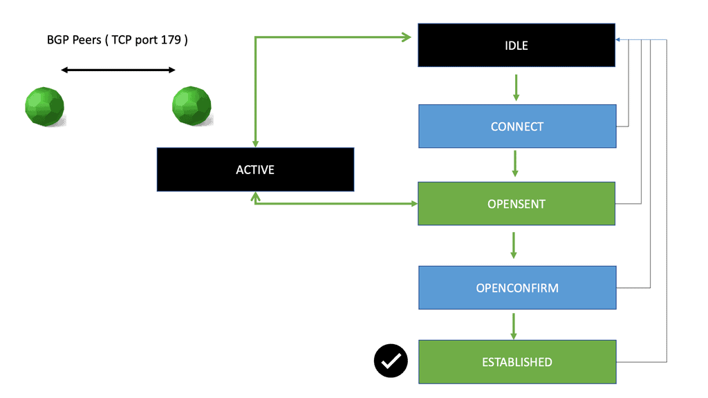
Pod data center: Example of computing resources

Component

Large

Medium

Small

vCPU per VM

 1 vCPU

0.5 vCPU

 0.25 vCPU

Cores per CPU

4

4

4

VM per CPU

4 VM

16 VM

32 VM

VM per vCPU oversubscription

1:1 ( 1 )

2:1 ( 0.5 )

4:1 ( 0.25 )

RAM allocation

16 GB dedicated 

8 GB dedicated

4 GB shared

Compute profiles can also be associated with VMware Distributed Resource Scheduling ( DRS ) profiles to prioritize specific classes of VMs.
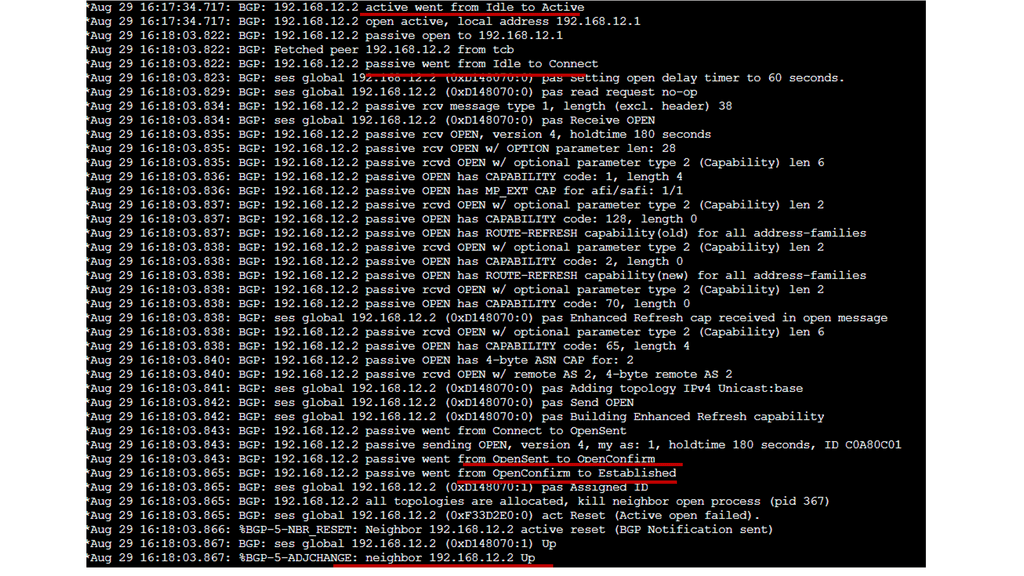
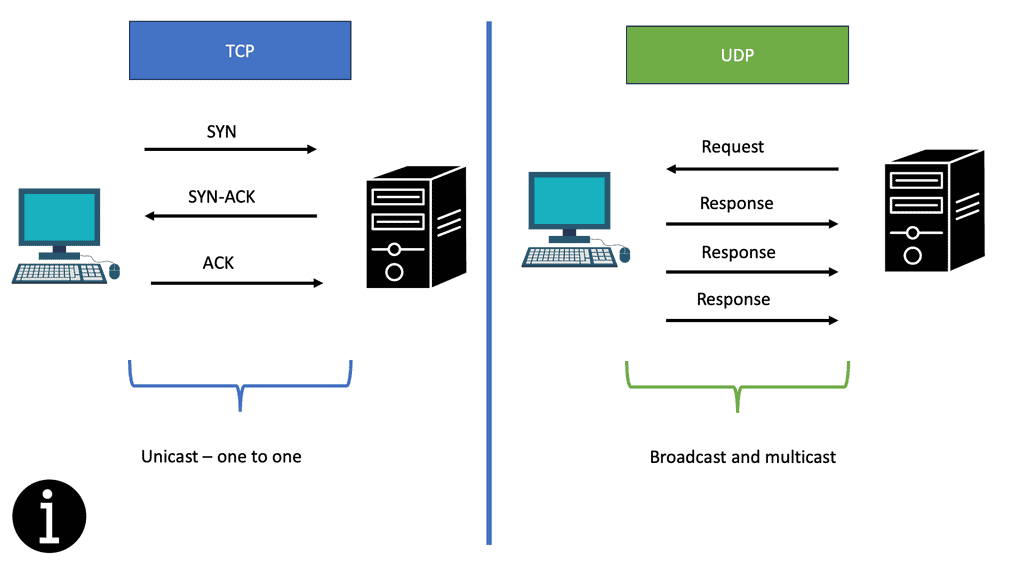
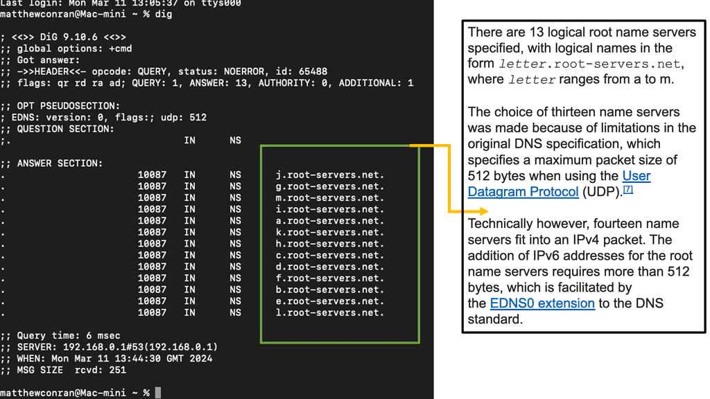
Modular building blocks: Storage Layer

This layer relates to storage allocation and the type of storage protection. For example, a GOLD tier could offer three tiers of RAID-10 storage using 15K rpm FC, 10K rpm FC, and SATA drives. While a BRONZE tier could offer just a single RAID-5 with SATA drives

Google Cloud Security

Understanding Google Compute Resources

Before diving into the importance of securing Google Compute resources, let’s first gain a clear understanding of what they entail. Google Compute Engine (GCE) allows users to create and manage virtual machines (VMs) on Google’s infrastructure. These VMs serve as the backbone of various applications and services hosted on the cloud platform.

As organizations increasingly rely on cloud-based infrastructure, the need for robust security measures becomes paramount. Google Compute resources may contain sensitive data, intellectual property, or even customer information. Without proper protection, these valuable assets are at risk of unauthorized access, data breaches, and other cyber threats. FortiGate provides a comprehensive security solution to mitigate these risks effectively.

FortiGate offers a wide range of features tailored to secure Google Compute resources. Its robust firewall capabilities ensure that only authorized traffic enters and exits the VMs, protecting against malicious attacks and unauthorized access attempts. Additionally, FortiGate’s intrusion prevention system (IPS) actively scans network traffic, detecting and blocking any potential threats in real-time.

Beyond traditional security measures, FortiGate leverages advanced threat prevention techniques to safeguard Google Compute resources. Its integrated antivirus and antimalware solutions continuously monitor the VMs, scanning for any malicious files or activities. FortiGate’s threat intelligence feeds and machine learning algorithms further enhance its ability to detect and prevent sophisticated cyber threats.
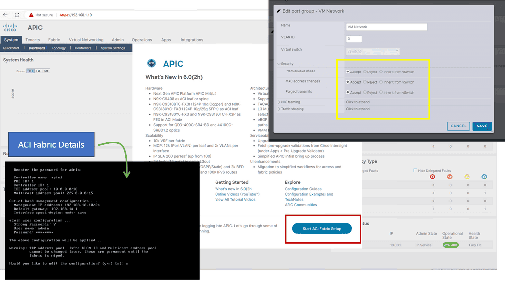
Summary: Cloud Data Centers

In the rapidly evolving digital age, data centers play a crucial role in storing and processing vast amounts of information. Traditional data centers have long been associated with high costs, inefficiencies, and limited scalability. However, a new paradigm has emerged – modular data center design. This innovative approach offers many benefits, revolutionizing how we think about data centers. This blog post explored the fascinating world of modular data center design and its impact on the industry.

Understanding Modular Data Centers

Modular data centers, also known as containerized data centers, are self-contained units that house all the essential components required for data storage and processing. These pre-fabricated modules are built off-site and can be easily transported and deployed. The modular design encompasses power and cooling systems, racks, servers, networking equipment, and security measures. This plug-and-play concept allows for rapid deployment, flexibility, and scalability, making it a game-changer in the data center realm.
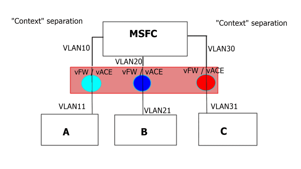
Benefits of Modular Data Center Design

Scalability and Flexibility

One key advantage of modular data center design is its scalability. Traditional data centers often face challenges in accommodating growth or adapting to changing needs. However, modular data centers offer the flexibility to scale up or down by simply adding or removing modules as required. This modular approach allows organizations to seamlessly align their data center infrastructure with their evolving business demands.

Cost Efficiency

Modular data center design brings notable cost advantages. Traditional data centers often involve significant upfront investments in construction, power distribution, cooling infrastructure, etc. In contrast, modular data centers reduce these costs by utilizing standardized modules that are pre-engineered and pre-tested. Additionally, scalability ensures that organizations only invest in what they currently need, avoiding unnecessary expenses.

Rapid Deployment

Time is of the essence in today’s fast-paced world. Traditional data centers can design, build, and deploy for months or even years. On the other hand, modular data centers can be rapidly deployed within weeks, thanks to their pre-fabricated nature. This accelerated deployment allows organizations to meet critical deadlines, swiftly respond to market demands, and gain a competitive edge.

Enhanced Efficiency and Performance

Optimized Cooling and Power Distribution

Modular data centers are designed with efficiency in mind. They incorporate advanced cooling technologies, such as hot and cold aisle containment, precision cooling, and efficient power distribution systems. These optimizations reduce energy consumption, lower operational costs, and improve performance.

Simplified Maintenance and Upgrades

Maintaining and upgrading traditional data centers can be a cumbersome and disruptive process. Modular data centers simplify these activities by providing a modularized framework. Modules can be easily replaced or upgraded without affecting the entire data center infrastructure. This modularity minimizes downtime and ensures continuous operations.

Conclusion:

In conclusion, modular data center design represents a significant leap forward in data centers. Its scalability, cost efficiency, rapid deployment, and enhanced efficiency make it a compelling choice for organizations looking to streamline their infrastructure. As technology continues to evolve, modular data centers offer the flexibility and agility required to meet the ever-changing demands of the digital landscape. Embracing this innovative approach will undoubtedly shape the future of data centers and pave the way for a more efficient and scalable digital infrastructure.