What Is VXLAN? Understanding Modern Network Overlays
Modern data centres require networks that can scale beyond traditional VLAN boundaries, support virtualised workloads and deliver predictable connectivity across routed infrastructure. Virtual Extensible LAN (VXLAN) addresses these requirements by extending Layer 2 Ethernet segments across a Layer 3 IP network.
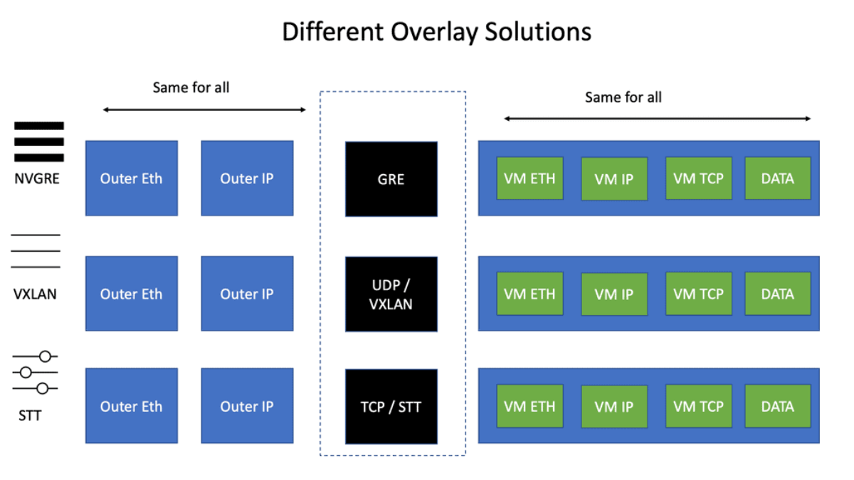
VXLAN separates the logical network from the physical transport infrastructure. Instead of relying on a large switched Layer 2 domain, VXLAN encapsulates Ethernet frames inside UDP/IP packets and transports them between VXLAN Tunnel Endpoints (VTEPs). This enables virtual networks to span multiple physical switches while the underlying fabric continues to use IP routing.
Each VXLAN segment is identified by a 24-bit VXLAN Network Identifier (VNI) . Compared with traditional 12-bit VLAN identifiers, VXLAN provides a substantially larger segmentation space, making it particularly useful for multi-tenant cloud platforms, software-defined data centres and large-scale virtualised environments.
Why VXLAN Matters in Modern Data Centres
Traditional Ethernet networks face practical limitations when stretched across large data centre environments. VLAN identifiers provide a limited segmentation space, large broadcast domains increase operational complexity, and Spanning Tree Protocol can prevent redundant Layer 2 links from forwarding simultaneously.
VXLAN enables a different architectural model. A routed leaf-spine underlay can use Equal-Cost Multi-Path (ECMP) forwarding across multiple active paths, while the VXLAN overlay provides logical Layer 2 connectivity independently of the physical topology. When combined with BGP Ethernet VPN (EVPN), the fabric can distribute MAC and IP reachability information through a control plane, reducing reliance on data-plane flooding.
What You Will Learn
This guide combines technical explanations with interactive network engineering exercises. You will explore VXLAN topology behaviour, examine encapsulated packets, compare forwarding mechanisms and investigate realistic overlay and underlay failures. The objective is not simply to understand what VXLAN is, but to understand how it behaves in a production data centre fabric.
Why VXLAN? Understanding the Limitations of Traditional Layer 2 Networks
Modern data centre networks must support thousands of virtual machines, multiple tenants, dynamic workload placement and high-bandwidth east-west traffic. Traditional Ethernet switching was not originally designed for this degree of scale, segmentation and mobility.
Conventional Layer 2 architectures rely on VLANs, MAC address learning and loop-prevention mechanisms such as Spanning Tree Protocol (STP). These technologies remain useful, but extending large Layer 2 domains across a data centre can introduce operational complexity, inefficient use of redundant links and limitations in the number of logical segments.
VXLAN was introduced to separate logical Layer 2 connectivity from the physical network topology. By encapsulating Ethernet frames inside UDP/IP packets, VXLAN allows a routed IP fabric to transport multiple isolated virtual networks without requiring the entire physical infrastructure to participate in the same Layer 2 broadcast domain.
1.1 — The Traditional Layer 2 Data Centre
In a traditional switched network, Ethernet frames are forwarded using destination MAC addresses. Switches learn source MAC addresses from incoming frames and maintain forwarding tables that associate MAC addresses with physical interfaces.
VLANs provide logical separation within this infrastructure. Each VLAN represents an independent Layer 2 broadcast domain, allowing different applications, departments or tenants to share physical switching hardware while maintaining separate Ethernet segments.
The challenge emerges when these networks grow. More servers create more MAC addresses, more applications require additional VLANs, and redundant physical links require careful loop prevention. Workload mobility can also require Layer 2 connectivity across multiple racks or physical locations.
Limited Segmentation Space
Traditional IEEE 802.1Q VLAN tags use a 12-bit VLAN identifier, providing 4,096 possible values, of which approximately 4,094 are available for normal VLAN use.
Spanning Tree Constraints
STP prevents Ethernet forwarding loops by selecting a loop-free active topology. Some redundant links may be blocked, preventing simultaneous forwarding.
MAC Address Table Growth
Virtualized servers can introduce many MAC addresses per physical switch port. Large Layer 2 domains increase forwarding table requirements and operational scale.
Workload Mobility
Moving workloads between physical hosts may require preserving network connectivity, addressing and policy across different switching locations.
The problem is not that Ethernet switching or VLANs are inherently unsuitable. The challenge is extending large numbers of logical Layer 2 segments across a growing physical network while preserving scalability, resilience and operational simplicity.
1.2 — VLAN Identifier Exhaustion
IEEE 802.1Q uses a 12-bit VLAN Identifier (VID). This provides 212, or 4,096, possible identifier values. VLAN IDs 0 and 4095 are reserved, leaving 4,094 usable VLAN identifiers in the normal VLAN namespace.
For a small enterprise, this may be sufficient. However, large cloud providers and multi-tenant data centres may require thousands of independent network segments for customers, applications, security zones and workload environments.
Logical Network Identifier Capacity
VXLAN introduces a 24-bit VXLAN Network Identifier (VNI). This significantly expands the available logical segment namespace. A VNI identifies an overlay segment, allowing different physical VLANs to map into the same logical VXLAN segment when required.
For example, VLAN 10 on one leaf switch and VLAN 20 on another leaf switch can both map to VNI 10010. The local VLAN numbers do not need to match, provided the VTEPs are configured to associate those VLANs with the same intended overlay bridge domain.
Consider a cloud provider operating infrastructure for 500 customers. Each customer requires eight isolated application networks for development, production, management, databases and supporting services.
This deployment already consumes almost the entire traditional VLAN identifier space if every segment requires a unique VLAN ID in one shared administrative namespace.
Adding more customers, environments or application tiers creates further demand. VXLAN allows the provider to allocate distinct VNIs without relying on a single global 12-bit VLAN namespace.
VLAN IDs can be reused in separate Layer 2 domains, so the 4,094-VLAN limit is not a universal limit on the number of tenants in an entire network. VXLAN is valuable because it provides a much larger overlay namespace and decouples logical segmentation from local physical VLAN assignments.
1.3 — Spanning Tree and Blocked Links
Ethernet networks must prevent forwarding loops. Unlike IP packets, ordinary Ethernet frames do not contain a hop-limit field that automatically expires as frames traverse switches.
A Layer 2 forwarding loop can cause broadcast storms, repeated frame replication, unstable MAC learning and severe network disruption. Spanning Tree Protocol prevents these conditions by selecting a loop-free forwarding topology.
Although this provides stability, a conventional spanning-tree topology may block redundant links. Consequently, installed physical bandwidth is not always available for active forwarding. Convergence following topology changes can also affect application connectivity.
Illustrative blocked redundant path
ECMP distributes eligible flows across available next hops.
Modern leaf-spine architectures commonly replace the large switched core with a routed IP underlay. Each leaf connects to multiple spine switches, and routing protocols maintain reachability across the fabric.
Equal-Cost Multi-Path (ECMP) forwarding allows traffic to use multiple equal-cost routes. Rather than relying on a spanning tree to disable redundant Layer 2 paths, the fabric uses Layer 3 routing and its associated convergence mechanisms.
VXLAN complements this architecture by transporting logical Layer 2 segments over the routed underlay. The physical fabric can therefore remain Layer 3 while connected workloads continue to experience the Layer 2 adjacency required by their applications.
VXLAN does not itself perform ECMP routing. ECMP is provided by the IP underlay. VXLAN enables Layer 2 overlay connectivity to use that routed infrastructure. The VXLAN UDP source port can provide entropy for flow-based ECMP hashing.
1.4 — Server Virtualization and MAC Scale
Server virtualization changes the relationship between physical switch ports and network endpoints. A single physical server can host many virtual machines, each with its own virtual network interface and MAC address.
In a conventional Ethernet design, switches learn the MAC addresses of communicating endpoints and store them in forwarding tables. As virtual machine populations increase, the number of learned addresses can grow substantially.
Large Layer 2 domains also require mechanisms for locating unknown destinations. When a destination MAC address is not known, unknown-unicast frames may be flooded within the relevant broadcast domain.
| Scaling Factor | Traditional Layer 2 Impact | VXLAN Fabric Approach |
|---|---|---|
| More virtual machines | Increasing MAC address learning and forwarding-table requirements | Logical segments distributed across VTEPs; EVPN can advertise remote MAC reachability |
| More application networks | Greater demand for VLAN identifiers and trunk configuration | 24-bit VNI namespace supports many overlay segments |
| Workload relocation | MAC location changes and possible VLAN extension requirements | Remote VTEP mappings can be updated through the overlay control plane |
| Unknown destinations | Flooding within the Layer 2 broadcast domain | BUM replication is still required in some cases; EVPN can reduce unnecessary flooding |
| Redundant fabric links | STP may block selected Layer 2 paths | Routed underlay supports ECMP across active IP paths |
VXLAN does not automatically eliminate MAC table requirements. VTEPs still need forwarding information for local and remote endpoints. However, the overlay architecture allows logical segments to be distributed across a routed fabric.
When combined with BGP EVPN, MAC and IP reachability information can be exchanged through a control plane. This provides more structured endpoint discovery, supports MAC mobility and can reduce reliance on traditional flood-and-learn forwarding.
1.5 — Why Workload Mobility Matters
Virtualization allows workloads to move between physical hosts for maintenance, resource optimisation, resilience and operational flexibility.
In some deployment models, a workload must preserve its IP address and Layer 2 connectivity when it moves. Traditional approaches may require VLANs to be extended across multiple racks or switching domains.
VXLAN enables the same logical overlay segment to be present on different physical leaf switches. A workload attached to VNI 10010 on Leaf A can communicate with another endpoint attached to VNI 10010 on Leaf B, even though the underlying network forwards traffic using IP routing.
In EVPN-based fabrics, control-plane updates can advertise changes in endpoint location. Remote VTEPs can then update their forwarding state to direct traffic toward the appropriate destination VTEP.
VXLAN provides the network mechanism for extending logical segments, but successful workload mobility also depends on application requirements, gateway design, security policy, address management and orchestration. Extending Layer 2 connectivity across distant sites is not always the preferred design.
1.6 — The Transition to Routed Overlay Fabrics
The evolution from traditional Layer 2 networks to VXLAN-based fabrics represents an important architectural shift. Instead of requiring the physical network to provide every logical Ethernet segment, the network separates two responsibilities:
The Underlay Network
Provides IP connectivity between VTEPs. Routing protocols maintain reachability, ECMP enables path diversity, and the physical topology can scale independently of tenant segmentation.
The VXLAN Overlay
Provides logical Ethernet segments identified by VNIs. VTEPs encapsulate and decapsulate traffic, while mechanisms such as BGP EVPN can distribute endpoint reachability.
This separation enables data centre architects to design a resilient routed fabric while delivering logical connectivity to workloads independently of their physical attachment points.
It also introduces new engineering responsibilities. The underlay must provide reliable VTEP reachability, the overlay must maintain correct endpoint mappings, and the fabric must account for encapsulation overhead, MTU, segmentation and control-plane convergence.
| Design Dimension | Traditional Approach | VXLAN-Based Fabric |
|---|---|---|
| Network segmentation | 12-bit VLAN identifiers | 24-bit VXLAN VNIs |
| Core transport | Often extended Layer 2 switching | Routed IP underlay |
| Path redundancy | STP or other L2 redundancy designs | IP routing and ECMP |
| Endpoint learning | Data-plane MAC learning | Flood-and-learn or EVPN control-plane distribution |
| Workload mobility | May require extended VLAN domains | Logical overlay segment extension |
| Operational visibility | Switch ports, VLANs and MAC tables | Underlay routes, VTEPs, VNIs, EVPN state and packet encapsulation |
VXLAN does not replace Ethernet, VLANs or IP routing. It combines them into an overlay architecture in which Ethernet segments are mapped to VNIs and transported across an IP network. Local VLANs still commonly connect endpoints to VTEPs, while the routed underlay transports encapsulated traffic.
1.7 — Design Trade-Offs and Operational Reality
VXLAN solves important scaling and architectural challenges, but it is not a universal replacement for traditional Layer 2 networking.
Overlay fabrics introduce additional headers, forwarding state and control-plane dependencies. Troubleshooting must distinguish between failures in the physical IP underlay and failures in the logical VXLAN overlay.
Engineers must also consider hardware forwarding capacity, VNI scale, EVPN route scale, broadcast replication, security policy, operational tooling and the ability to observe encapsulated traffic across the network.
| VXLAN Advantage | Engineering Responsibility |
|---|---|
| Large logical segment space | VNI allocation, lifecycle management and tenant isolation |
| Routed underlay transport | IP reachability, routing convergence and ECMP path health |
| Flexible workload placement | MAC mobility, gateway consistency and policy enforcement |
| Overlay encapsulation | MTU planning, packet visibility and forwarding performance |
| EVPN control-plane learning | BGP session health, route import/export and endpoint state consistency |
VXLAN also provides segmentation rather than encryption. Security still requires appropriate access controls, isolation policies and protection of the transport infrastructure.
Section 1 — Engineering Takeaways
Why VXLAN? Explore the Limits of Layer 2
Compare a traditional VLAN-based network with a routed VXLAN overlay. Select an engineering challenge, change the architecture and run a packet journey to see what changes.
VXLAN separates logical Layer 2 segments from the physical transport network, enabling Ethernet overlays to operate across a routed IP fabric.
VXLAN Architecture: Understanding the Underlay, Overlay and VTEPs
VXLAN architecture separates the physical network responsible for IP packet transport from the logical network that provides Ethernet connectivity to applications. This separation is the foundation of modern routed data centre fabrics.
In a VXLAN environment, the underlay network provides routed IP connectivity between tunnel endpoints, while the overlay network represents the virtual Layer 2 segments transported across that infrastructure. VXLAN Tunnel Endpoints (VTEPs) connect these two architectural layers.
Understanding the relationship between the underlay, overlay, VTEPs and VXLAN Network Identifiers (VNIs) is essential for designing, operating and troubleshooting VXLAN fabrics. A failure in any of these components can interrupt workload connectivity even when other parts of the network appear healthy.
2.1 — The Three Architectural Layers
A VXLAN fabric can be understood through three primary architectural components: the physical IP underlay, the logical VXLAN overlay and the VTEPs that perform encapsulation and decapsulation.
IP Underlay Network
The routed physical network connecting leaf and spine switches. It provides reachability between VTEP IP addresses and forwards outer IP packets using normal Layer 3 routing.
VXLAN Overlay Network
Logical Ethernet segments identified by VNIs. The overlay allows workloads connected to different physical leaf switches to participate in the same virtual Layer 2 network.
VXLAN Tunnel Endpoint
A VTEP encapsulates local Ethernet frames into VXLAN UDP/IP packets and decapsulates incoming VXLAN traffic before forwarding the inner frames toward connected endpoints.
VXLAN Network Identifier
A 24-bit VNI identifies the logical overlay segment associated with encapsulated traffic. VNIs allow many isolated virtual networks to share the same routed fabric.
The underlay forwards packets using outer IP addresses. The overlay identifies the logical Ethernet segment using the VNI. The VTEP connects both functions by adding or removing the VXLAN encapsulation.
2.2 — VXLAN Leaf-Spine Fabric Architecture
Modern VXLAN deployments commonly use a leaf-spine architecture. Each leaf switch connects to multiple spine switches, creating a routed topology with predictable path diversity and multiple equal-cost forwarding options.
Leaf switches frequently act as VTEPs, connecting local servers or virtual machines to the overlay. Spine switches provide IP transport between leaf VTEPs and do not normally need to inspect the VXLAN headers or tenant Ethernet frames.
The leaf-spine topology is particularly suitable for VXLAN because it provides consistent routed connectivity between VTEPs and can distribute traffic across multiple available paths.
The physical network does not need to extend tenant VLANs through the spines. Instead, each leaf encapsulates local traffic using VXLAN and sends the resulting outer IP packet toward the remote VTEP.
2.3 — The IP Underlay Network
The underlay is responsible for transporting encapsulated VXLAN packets between VTEPs. It must provide reliable IP connectivity between the VTEP source and destination addresses.
In many deployments, each VTEP uses a loopback interface as its VXLAN source address. The underlay routing system advertises reachability to these loopback addresses so that remote VTEPs can forward encapsulated traffic correctly.
Common underlay routing approaches include OSPF, IS-IS and eBGP. The appropriate protocol depends on the fabric architecture, operational requirements and platform capabilities.
| Underlay Component | Engineering Role | Operational Check |
|---|---|---|
| Physical links | Provide connectivity between leaf and spine switches | Interface status, errors, speed and utilization |
| Routing protocol | Advertises reachability to VTEP addresses | OSPF, IS-IS or BGP neighbor and route state |
| VTEP loopback | Stable source or destination address for VXLAN packets | Route lookup and loopback reachability |
| ECMP | Distributes eligible traffic across equal-cost paths | Installed next hops and flow distribution |
| MTU | Accommodates additional VXLAN encapsulation overhead | End-to-end packet size and fragmentation behavior |
If Leaf A cannot route traffic to Leaf B's VTEP address, the VXLAN overlay cannot deliver encapsulated packets between them. The VNI configuration may be correct, but the data plane will still fail because the underlay lacks usable IP reachability.
2.4 — The VXLAN Overlay Network
The overlay represents the logical networks carried across the IP underlay. Each Layer 2 VXLAN segment is identified by a VNI, and participating VTEPs associate local attachment circuits or VLANs with that identifier.
Consider two servers connected to different leaf switches. Both servers belong to the same logical network, represented by VNI 10010. The servers can exchange Ethernet frames even though the physical switches between them operate as Layer 3 routers.
VXLAN encapsulation allows the original Ethernet frame to remain intact as it crosses the underlay. The receiving VTEP removes the outer encapsulation and forwards the inner frame within the appropriate local bridge domain.
Local VLAN 10
Host A connects to VLAN 10. Leaf A maps this VLAN to VNI 10010 and encapsulates traffic destined for remote endpoints in that overlay segment.
Local VLAN 20
Host B connects to VLAN 20. Leaf B maps VLAN 20 to the same VNI 10010, placing both endpoints in the intended logical Layer 2 segment.
Local VLAN identifiers do not have to match across VTEPs. The VNI identifies the shared overlay bridge domain. However, the mappings must be consistent with the intended tenant segmentation and control-plane configuration.
2.5 — The Role of the VTEP
A VXLAN Tunnel Endpoint is the device or software component responsible for converting Ethernet traffic into VXLAN packets and back again.
VTEPs may exist in physical switches, virtual switches, hypervisors or other supported network devices. In a common hardware leaf-spine design, the leaf switches act as VTEPs.
| VTEP Function | Description |
|---|---|
| Encapsulation | Adds VXLAN, UDP, IP and outer Ethernet headers to an original Ethernet frame |
| Decapsulation | Removes the outer headers and restores the original Ethernet frame for local forwarding |
| VNI mapping | Associates local bridge domains or VLANs with VXLAN segment identifiers |
| Remote endpoint forwarding | Determines the destination VTEP for known remote MAC addresses |
| BUM replication | Handles broadcast, unknown unicast and multicast traffic using the configured replication mechanism |
| EVPN integration | Uses advertised MAC/IP reachability information when BGP EVPN is deployed |
A VTEP needs to determine both the logical segment associated with a frame and the remote VTEP that should receive it. The method used to discover remote endpoints depends on whether the fabric uses flood-and-learn or a control plane such as BGP EVPN.
2.6 — Example VTEP Configuration
The following simplified Cisco NX-OS-style example illustrates the relationship between a local VLAN, VNI and NVE interface. The example is conceptual and may require additional platform- specific commands, feature enablement and control-plane configuration.
feature nv overlay

vlan 10
  vn-segment 10010

interface loopback1
  ip address 10.0.0.11/32

interface nve1
  no shutdown
  host-reachability protocol bgp
  source-interface loopback1
  member vni 10010
    ingress-replication protocol bgp
In this example, VLAN 10 maps to VNI 10010. Loopback1 provides the local VTEP source address, and interface NVE1 represents the VXLAN tunnel interface.
The BGP EVPN control plane can advertise reachability information and support ingress replication membership. However, the exact configuration model varies between hardware platforms, operating systems and software versions.
2.7 — Packet Forwarding Across the Fabric
When a local endpoint sends an Ethernet frame to a remote endpoint in the same VNI, the ingress VTEP encapsulates the frame and forwards it across the IP underlay.
The original source and destination MAC addresses remain part of the inner Ethernet frame. The outer IP header identifies the source and destination VTEPs.
Intermediate spine routers forward the packet based on the outer destination IP address. They do not need to learn tenant MAC addresses or participate in the tenant Layer 2 bridge domain.
The VXLAN tunnel is a logical relationship between VTEPs. It is not necessarily a dedicated physical path. Encapsulated packets may traverse different equal-cost underlay routes depending on the ECMP hashing algorithm and network state.
2.8 — ECMP and Underlay Path Diversity
One of the major advantages of a routed leaf-spine underlay is the ability to use multiple equal-cost paths simultaneously.
VXLAN uses UDP encapsulation, allowing the underlay to distinguish flows through outer header fields. Many implementations derive the UDP source port from a hash of inner packet information to provide entropy for ECMP.
This enables different encapsulated flows to be distributed across available underlay next hops. However, ECMP is commonly flow-based, so a single flow may continue to use one selected path rather than being distributed packet by packet.
Multiple Active Paths
Leaf A can reach Leaf B through Spine 1 or Spine 2. The underlay may install both equal-cost next hops and distribute eligible VXLAN flows across them.
Underlay Reconvergence
If one path fails, the routing system removes the unavailable next hop. Traffic can continue over remaining paths, subject to detection, convergence and forwarding updates.
2.9 — Where BGP EVPN Fits
VXLAN defines a data-plane encapsulation mechanism. It does not, by itself, define a complete mechanism for distributing remote endpoint reachability throughout the fabric.
Early VXLAN deployments commonly relied on data-plane learning and multicast-based replication. Modern data centre fabrics frequently combine VXLAN with BGP Ethernet VPN (EVPN) to provide a scalable control-plane mechanism.
EVPN can advertise MAC/IP reachability, identify participating VTEPs and support endpoint mobility. It also enables features such as distributed gateway architectures and inter-subnet routing.
| Component | Responsibility |
|---|---|
| VXLAN | Encapsulates Ethernet traffic inside UDP/IP packets |
| IP Underlay | Provides routed reachability between VTEP addresses |
| BGP EVPN | Distributes endpoint reachability and overlay control-plane information |
| VTEP | Performs encapsulation, decapsulation and overlay forwarding |
| VNI | Identifies the logical overlay segment or routing context |
VXLAN is the data-plane encapsulation technology. BGP EVPN is a control-plane technology used to distribute overlay reachability information. They are commonly deployed together, but they perform different architectural roles.
2.10 — VXLAN Architecture Design Requirements
A successful VXLAN fabric depends on more than enabling an NVE interface and assigning a VNI. The underlay and overlay must be designed as related but independently observable systems.
| Requirement | Why It Matters |
|---|---|
| VTEP IP reachability | Remote tunnel endpoints must be reachable through the routed underlay |
| Consistent VNI mappings | Logical segments must map to the intended bridge domains |
| Appropriate MTU | Encapsulation adds header overhead beyond the original frame size |
| Control-plane stability | EVPN routes and endpoint mappings must remain accurate during changes |
| Resilient underlay | Routing and ECMP must recover from physical path failures |
| Tenant isolation | VNIs, VRFs and security policy must prevent unintended connectivity |
| Operational visibility | Engineers need to inspect routing, NVE peers, VNIs, EVPN routes and forwarding state |
Troubleshooting should begin by determining whether the fault exists in the underlay, overlay or endpoint attachment configuration.
For example, a missing VTEP route indicates an underlay reachability problem, while a VNI mismatch or missing EVPN route may indicate an overlay configuration or control-plane problem.
A healthy BGP EVPN session does not guarantee successful VXLAN forwarding. The fabric must also have correct VNI membership, valid remote endpoint mappings, usable VTEP routes, sufficient MTU and appropriate forwarding policies.
Section 2 — Engineering Takeaways
VXLAN Architecture Explorer: Underlay, Overlay and VTEPs
Investigate a two-leaf, two-spine VXLAN fabric. Select individual devices to inspect their roles, switch between physical and logical network views, and trace the journey of an Ethernet frame across the IP underlay.
Leaf A · VXLAN Tunnel Endpoint
Leaf A is a VTEP. It receives Ethernet frames from Host A, maps the local VLAN to a VNI and encapsulates frames for remote VTEPs.
The underlay transports IP packets between VTEPs. The VXLAN overlay provides logical Ethernet connectivity between workloads. The spines forward on outer IP headers and do not normally need to inspect the inner Ethernet frame.
VXLAN Encapsulation and Packet Forwarding
VXLAN enables an Ethernet frame to cross a routed IP network without requiring intermediate routers to participate in the original Layer 2 broadcast domain. It achieves this by encapsulating the Ethernet frame inside a VXLAN header, UDP datagram and outer IP packet.
The original Ethernet frame remains the inner frame, while the newly added transport headers identify the source and destination VXLAN Tunnel Endpoints (VTEPs). This separation allows the physical network to forward traffic using ordinary IP routing while the overlay preserves logical Ethernet connectivity between workloads.
Understanding the exact encapsulation format is essential for troubleshooting VXLAN fabrics. Engineers must distinguish the inner and outer addressing information, verify the correct VXLAN Network Identifier (VNI), account for encapsulation overhead and confirm that the receiving VTEP can decapsulate and forward the original frame.
3.1 — What Happens During VXLAN Encapsulation?
When Host A sends an Ethernet frame toward Host B in the same logical VXLAN segment, the ingress VTEP first determines the bridge domain and VNI associated with the incoming frame.
If the destination MAC address is reachable through a remote VTEP, the ingress device encapsulates the original Ethernet frame with a VXLAN header and additional UDP/IP transport headers.
The resulting packet is forwarded through the routed underlay toward the destination VTEP. Intermediate routers inspect the outer IP destination address and do not need to understand the tenant's inner Ethernet addressing.
Original Ethernet Frame
Contains the original source and destination MAC addresses, optional VLAN information and the payload generated by the communicating hosts.
VXLAN Transport Headers
Include the VXLAN VNI, UDP header, outer source and destination IP addresses and the Ethernet header used on the current physical link.
The inner Ethernet frame identifies the communicating endpoints. The outer IP header identifies the VTEPs transporting that frame. The VNI identifies the logical overlay segment in which the frame belongs.
3.2 — The Complete VXLAN Packet Structure
A conventional VXLAN packet consists of an original Ethernet frame encapsulated inside an 8-byte VXLAN header, an 8-byte UDP header and an outer IP packet. An outer Ethernet header is also used when the encapsulated packet is transmitted across an Ethernet underlay link.
The outer Ethernet header changes as the encapsulated packet moves between physical Layer 3 hops. By contrast, the outer source and destination VTEP IP addresses normally remain constant across the underlay path.
The inner Ethernet frame is preserved through the VXLAN tunnel, allowing the destination VTEP to deliver it into the corresponding local bridge domain after decapsulation.
3.3 — Understanding the 8-Byte VXLAN Header
The standard VXLAN header defined by RFC 7348 is eight bytes long. Its most important field is the 24-bit VXLAN Network Identifier, which identifies the logical network segment associated with the encapsulated frame.
The header also contains flags and reserved fields. The I flag indicates that the VNI field is valid. In the original VXLAN format, the remaining reserved bits are transmitted as zero.
| Field | Size | Purpose |
|---|---|---|
| Flags | 8 bits | Includes the I flag indicating that the VNI is valid |
| Reserved | 24 bits | Reserved fields in the original VXLAN header |
| VNI | 24 bits | Identifies the logical VXLAN segment |
| Reserved | 8 bits | Reserved final byte |
A VTEP uses the VNI to select the intended overlay bridge domain. If the receiving VTEP does not have the appropriate VNI configured, it cannot correctly deliver the frame into that logical segment.
3.4 — Inner and Outer Addressing
VXLAN packets contain two addressing contexts. The inner headers describe the communicating workloads, while the outer headers describe how the encapsulated packet travels through the physical IP fabric.
| Address Field | Example | Function |
|---|---|---|
| Inner source MAC | 00:11:22:33:44:01 | Original Host A MAC |
| Inner destination MAC | 00:11:22:33:44:02 | Original Host B MAC |
| Inner source IP | 192.168.10.11 | Host A IP address |
| Inner destination IP | 192.168.10.12 | Host B IP address |
| Outer source IP | 10.0.0.11 | Leaf A VTEP address |
| Outer destination IP | 10.0.0.12 | Leaf B VTEP address |
| VXLAN VNI | 10010 | Overlay bridge domain |
Spine routers use the outer destination IP address to forward the encapsulated packet. They do not need routes for the inner host IP addresses when simply providing underlay transport.
The receiving VTEP uses the VXLAN header and local forwarding information to identify the correct bridge domain and deliver the inner frame.
3.5 — End-to-End VXLAN Packet Journey
Consider Host A connected to Leaf A and Host B connected to Leaf B. Both hosts belong to VNI 10010, and the underlay provides IP connectivity between the two VTEPs.
Step 1 — Original Ethernet Frame
Host A creates an Ethernet frame containing Host B's destination MAC address. The frame enters Leaf A through a local access interface associated with the intended bridge domain.
Step 2 — VNI and Remote VTEP Selection
Leaf A identifies the local bridge domain and associated VNI. Its forwarding information indicates that Host B's MAC address is reachable through Leaf B's VTEP.
This remote mapping may have been learned through flood-and-learn forwarding or advertised by BGP EVPN.
Step 3 — Encapsulation and IP Forwarding
Leaf A adds the VXLAN, UDP and outer IP headers. The outer destination becomes Leaf B's VTEP address, 10.0.0.12.
The underlay routing table determines the next hop. If multiple equal-cost paths exist, ECMP hashing may select one of them.
Step 4 — Decapsulation at Leaf B
Leaf B receives the VXLAN packet, validates the relevant encapsulation information and identifies VNI 10010.
It removes the outer headers and processes the original Ethernet frame in the associated local bridge domain.
Step 5 — Delivery to Host B
Leaf B forwards the recovered Ethernet frame toward Host B through the appropriate local attachment interface.
This example assumes that the destination MAC-to-VTEP mapping is already known. If the destination is unknown, the fabric may need to perform BUM replication or another endpoint discovery operation. These mechanisms are covered in Section 4.
3.6 — VXLAN UDP Ports and ECMP Entropy
Standard VXLAN uses UDP destination port 4789. The UDP source port is commonly derived from a hash of the inner packet fields.
This variable source port provides additional entropy for underlay ECMP hashing. Without suitable entropy, many VXLAN flows between the same pair of VTEPs could hash onto the same physical path.
Port 4789
The standard VXLAN destination port. Receiving VTEPs use the configured port to identify VXLAN traffic for processing.
Flow-Based Entropy
A source port chosen using a hash of inner traffic fields can help distribute different flows across ECMP paths.
ECMP is typically flow-based rather than packet-based. A single flow may remain on one underlay path, while different flows can be distributed across other available paths.
Some older VXLAN implementations and lab environments used non-standard or configurable UDP destination ports. Your original VXLAN lab used port 1024 explicitly. Both VTEPs must use compatible port settings. For new standards-based deployments, UDP 4789 is the normal choice.
3.7 — VXLAN Encapsulation Overhead and MTU
Encapsulation increases packet size because additional headers are inserted around the original Ethernet frame.
For a typical VXLAN packet transported over IPv4, the additional headers consist of:
The 50-byte calculation assumes an untagged inner Ethernet frame, a minimum 20-byte outer IPv4 header and no optional extensions. It excludes the outer Ethernet header and FCS, which are link-layer overhead.
If the original host sends a 1,500-byte IP packet, the VXLAN encapsulation produces a 1,550-byte outer IPv4 packet when the inner Ethernet header is included.
Therefore, an underlay IP MTU of at least 1,550 bytes is required for this specific untagged IPv4 example without outer IP fragmentation.
Many data centre operators configure larger MTUs, often using jumbo-frame support, to provide additional headroom for encapsulation, VLAN tags and other transport requirements.
VXLAN does not automatically require a particular jumbo MTU such as 9,000 bytes. The required underlay MTU depends on the inner packet size and encapsulation format. Insufficient MTU can cause fragmentation, packet drops or application-level failures.
3.8 — VXLAN Packet Capture Analysis
Packet captures are one of the most useful tools for understanding VXLAN forwarding. A capture taken on an underlay link reveals the outer Ethernet, IP, UDP and VXLAN headers.
In Wireshark, an engineer can inspect the outer source and destination VTEP addresses, UDP destination port, VNI and encapsulated Ethernet frame.
Frame: VXLAN encapsulated ICMP

Outer Ethernet:
  Source MAC:      Underlay next-hop MAC
  Destination MAC: Underlay next-hop MAC

Outer IPv4:
  Source IP:       10.0.0.11
  Destination IP:  10.0.0.12
  Protocol:        UDP (17)

UDP:
  Source Port:     52341
  Destination:     4789

VXLAN:
  Flags:           0x08 (I flag set)
  VNI:             10010

Inner Ethernet:
  Source MAC:      00:11:22:33:44:01
  Destination MAC: 00:11:22:33:44:02

Inner IPv4:
  Source IP:       192.168.10.11
  Destination IP:  192.168.10.12
  Protocol:        ICMP

ICMP:
  Type:            Echo Request
A useful first check is to confirm that the outer destination IP address matches the expected remote VTEP.
The next check is the VNI. A correct VTEP destination with an incorrect VNI can still result in failed forwarding.
Finally, the inner Ethernet and IP headers should match the expected workload traffic. This helps determine whether the issue exists before encapsulation, inside the overlay or after decapsulation.
3.9 — Common VXLAN Packet Forwarding Failures
| Failure | Likely Symptom | Engineering Check |
|---|---|---|
| Incorrect VNI | Remote VTEP cannot deliver traffic into intended segment | Verify local VLAN-to-VNI mappings and NVE membership |
| Missing VTEP route | Encapsulated packets cannot reach remote VTEP | Check underlay routing and VTEP reachability |
| UDP port mismatch | Receiver may not recognise VXLAN packets | Verify configured VXLAN destination port |
| Insufficient MTU | Large packets fail while smaller packets work | Test end-to-end encapsulated packet sizes |
| Missing remote MAC mapping | Traffic is flooded or cannot be forwarded | Inspect MAC tables and EVPN reachability |
| Underlay path failure | Packet loss or temporary interruption | Verify routing convergence and ECMP next hops |
| Security policy drop | Encapsulated traffic is filtered in transit | Inspect ACLs, firewalls and UDP 4789 reachability |
Follow the packet in order: original host frame, local bridge-domain mapping, remote MAC-to-VTEP resolution, VXLAN encapsulation, underlay IP forwarding, destination VTEP decapsulation and final host delivery. This method helps isolate the failing stage rather than treating the overlay as one opaque tunnel.
3.10 — Operational Verification Commands
On a Cisco NX-OS-based VXLAN fabric, several operational commands can help validate packet forwarding. Exact output and availability vary by platform and release.
show nve interface
show nve peers
show nve vni

show mac address-table
show l2route evpn mac all

show ip route 10.0.0.12
show ip interface brief

show bgp l2vpn evpn summary
show bgp l2vpn evpn

show interface counters errors
A successful troubleshooting investigation should confirm that the local VTEP is operational, the expected VNI is active, the remote VTEP is reachable and the required forwarding information exists.
If the fabric uses BGP EVPN, the engineer should also inspect EVPN routes and their imported reachability information. However, a healthy BGP session alone does not prove successful VXLAN data-plane forwarding.
Section 3 — Engineering Takeaways
VXLAN Encapsulation and Packet Header Explorer
Build and inspect a VXLAN packet. Explore how the original Ethernet frame is wrapped in VXLAN, UDP, IP and Ethernet headers, then trace the packet across the underlay and examine its MTU requirements.
Inner Ethernet Header
The original Ethernet header identifies the source and destination MAC addresses. VXLAN transports this frame across the routed IP network without requiring intermediate spines to inspect its inner MAC addresses.
VXLAN preserves the original Ethernet frame inside a new transport packet. The underlay forwards using the outer IP destination, while the remote VTEP removes encapsulation and delivers the original Ethernet frame. Always account for encapsulation overhead when planning the underlay MTU.
VXLAN Flood-and-Learn and the BGP EVPN Control Plane
VXLAN defines how Ethernet frames are encapsulated and transported across an IP network. However, encapsulation alone does not explain how a VTEP discovers remote MAC addresses, identifies participating tunnel endpoints or determines where unknown traffic should be sent.
These functions are handled through endpoint learning and control-plane mechanisms. Traditional VXLAN deployments commonly relied on flood-and-learn forwarding, while modern data centre fabrics frequently use BGP Ethernet VPN (EVPN) to distribute endpoint reachability and overlay membership information.
Understanding both approaches is important because they solve similar forwarding problems through fundamentally different mechanisms. Flood-and-learn depends heavily on data-plane observation, whereas EVPN enables endpoint information to be advertised through a routing control plane.
4.1 — Why VXLAN Needs Endpoint Discovery
Consider two servers connected to different leaf switches in the same VXLAN segment. Host A is connected to Leaf A, while Host B is connected to Leaf B.
Before Leaf A can send a known-unicast VXLAN packet directly to Leaf B, it must determine which remote VTEP is responsible for Host B's destination MAC address.
This requires a mapping between the remote MAC address and the destination VTEP IP address.
MAC-to-VTEP Mapping
Associates a remote endpoint MAC address with the VTEP IP address through which the endpoint is reachable.
VNI Participation
Identifies the VTEPs participating in a particular VXLAN segment, allowing appropriate forwarding and replication.
VXLAN encapsulation provides a way to transport a frame, but the ingress VTEP must still determine the correct remote VTEP destination. Flood-and-learn and BGP EVPN provide different methods for discovering and maintaining that forwarding information.
4.2 — Traditional VXLAN Flood-and-Learn
Traditional VXLAN flood-and-learn operates in a way that resembles conventional Ethernet switching. A VTEP learns MAC addresses from observed traffic and uses flooding when the destination is unknown.
When an ingress VTEP receives a frame destined for an unknown MAC address, it replicates the frame to other participating VTEPs using the configured BUM delivery mechanism.
When the destination endpoint responds, the receiving VTEPs can learn the association between the source MAC address and the originating VTEP address.
Flood-and-learn is conceptually straightforward, but it introduces operational considerations around flooding scope, replication, MAC aging and endpoint mobility.
4.3 — Understanding BUM Traffic
BUM stands for Broadcast, Unknown Unicast and Multicast. These traffic categories require special handling because the ingress VTEP may not have a single known destination VTEP.
| Traffic Type | Example | Typical VXLAN Handling |
|---|---|---|
| Broadcast | ARP request | Replicated to participating VTEPs unless locally suppressed or otherwise handled |
| Unknown Unicast | Frame with an unknown destination MAC | Flooded within the relevant overlay segment when unknown-unicast flooding is enabled |
| Multicast | Application multicast Ethernet traffic | Delivered according to the configured overlay multicast and replication behavior |
BUM replication must be constrained to the appropriate VXLAN segment. A VTEP should not replicate tenant traffic indiscriminately across unrelated VNIs.
Excessive BUM traffic can consume bandwidth and processing resources. Large VXLAN environments therefore benefit from careful replication design, endpoint learning controls and features such as ARP suppression.
4.4 — Multicast Versus Ingress Replication
VXLAN can distribute BUM traffic through underlay multicast or through ingress replication. Both approaches deliver copies to participating VTEPs, but they differ in where packet replication occurs.
Multicast-Based Replication
VTEPs send VXLAN BUM traffic toward a multicast group. Multicast-capable underlay devices replicate traffic along the distribution tree.
Ingress Replication
The ingress VTEP creates individual VXLAN copies for remote VTEPs in the replication list. Underlay multicast is not required.
| Characteristic | Multicast | Ingress Replication |
|---|---|---|
| Underlay multicast | Required | Not required |
| Replication location | Multicast distribution tree in the network | Ingress VTEP |
| Source VTEP load | Generally fewer source-generated copies | Increases with the number of remote replication destinations |
| Operational dependency | Multicast routing and group membership | Accurate remote VTEP replication list |
| Common deployment | Traditional multicast-based VXLAN fabrics | Frequently used with BGP EVPN |
Ingress replication is popular in EVPN fabrics because the control plane can distribute the information needed to construct replication lists without requiring multicast routing throughout the underlay.
4.5 — Introducing the BGP EVPN Control Plane
BGP EVPN uses Multiprotocol BGP to distribute overlay reachability information between participating network devices.
Rather than relying exclusively on observed VXLAN traffic to learn remote endpoint locations, EVPN allows VTEPs to advertise reachability information through BGP routes.
This separates the control plane, responsible for distributing endpoint information, from the data plane, responsible for carrying encapsulated Ethernet traffic.
A BGP EVPN route reflector can distribute overlay reachability information between leaf VTEPs without becoming part of the VXLAN data path.
This architecture supports scalable endpoint learning and allows network engineers to inspect the control-plane state independently from the forwarding path.
4.6 — EVPN Route Type 2: MAC/IP Advertisement
EVPN Route Type 2 is the MAC/IP Advertisement Route. It allows a VTEP to advertise endpoint MAC reachability and, when applicable, associated IP address information.
For example, Leaf B can advertise that Host B's MAC address is reachable through Leaf B's VTEP.
Leaf A can import the appropriate EVPN route and install forwarding information for Host B without needing to discover the remote MAC location solely through flooding.
EVPN Route Type: 2
Route: MAC/IP Advertisement

MAC Address:
  00:11:22:33:44:02

IP Address:
  192.168.10.12

Advertising VTEP:
  10.0.0.12

Overlay Segment:
  VNI 10010

BGP Next Hop:
  10.0.0.12

Result:
  Remote MAC reachability learned
  through the EVPN control plane
Type 2 routes reduce dependence on data-plane flooding for discovering known remote endpoints. The receiving VTEP can install the advertised MAC-to-VTEP mapping after validating and importing the route.
4.7 — EVPN Route Type 3: Inclusive Multicast Ethernet Tag
EVPN Route Type 3 is the Inclusive Multicast Ethernet Tag (IMET) Route. It advertises information used to establish participation in a broadcast domain and construct BUM delivery state.
In an ingress-replication design, IMET routes can help VTEPs discover the remote peers that should receive replicated BUM traffic for the relevant overlay segment.
Endpoint Reachability
Advertises MAC addresses and optional IP bindings, enabling remote endpoint forwarding information to be installed.
Broadcast Domain Membership
Supports discovery of participating VTEPs and establishment of BUM delivery state, including ingress replication lists.
| Route Type | Primary Role | Operational Importance |
|---|---|---|
| Type 2 | MAC/IP Advertisement | Known-unicast endpoint reachability |
| Type 3 | Inclusive Multicast Ethernet Tag | BUM membership and replication information |
| Type 1 | Ethernet Auto-Discovery | Multihoming procedures and mass withdrawal |
| Type 4 | Ethernet Segment | Ethernet segment discovery and designated forwarder election |
| Type 5 | IP Prefix Advertisement | IP prefix reachability in EVPN-based routing architectures |
Type 2 and Type 3 are particularly important when understanding basic VXLAN EVPN Layer 2 forwarding.
Other EVPN route types support more advanced designs, including multihoming, distributed routing and IP prefix advertisement.
4.8 — EVPN Endpoint Learning Sequence
The following example shows how Host B's reachability can become available to Leaf A through BGP EVPN.
EVPN distributes information about where an endpoint is located. VXLAN carries the actual Ethernet frame. The BGP route reflector normally participates in control-plane distribution but does not need to forward the encapsulated tenant data traffic.
4.9 — ARP Suppression in VXLAN EVPN
In a conventional Layer 2 network, ARP requests are broadcast to discover the MAC address associated with an IPv4 address.
In a VXLAN fabric, uncontrolled ARP broadcasting can create additional BUM traffic across the overlay.
With EVPN-based ARP suppression, a VTEP can use known IP-to-MAC bindings to answer certain ARP requests locally, reducing the need to flood those requests to remote VTEPs.
ARP Flooding
An ARP request may be replicated across the VXLAN segment to discover the destination MAC address.
Local ARP Response
A VTEP with a valid learned IP-to-MAC binding may answer the ARP request locally without flooding it.
ARP suppression reduces unnecessary broadcast traffic when valid endpoint bindings are available. Unknown or unresolved requests may still require flooding or other resolution mechanisms, depending on platform behavior and configuration.
4.10 — MAC Mobility and Endpoint Movement
Virtual machines and workloads may move between hosts or leaf switches while retaining their original MAC and IP addresses.
This creates a forwarding challenge: remote VTEPs must update their endpoint mappings when a MAC address becomes reachable through a different VTEP.
BGP EVPN supports MAC mobility procedures, including a MAC Mobility extended community and sequence numbers used to help distinguish newer endpoint location advertisements.
MAC mobility is especially important in virtualized environments where workload placement can change without requiring the endpoint to obtain a new IP address.
Repeated movement of the same MAC address between VTEPs can indicate legitimate workload migration, but it may also indicate a loop, duplicate MAC address or configuration error. Engineers should inspect mobility events and sequence numbers before assuming the movement is expected.
4.11 — Flood-and-Learn Versus BGP EVPN
| Capability | Flood-and-Learn | BGP EVPN |
|---|---|---|
| Remote MAC learning | Observed data-plane traffic | Control-plane Type 2 advertisements |
| Unknown destinations | Typically flooded | May be flooded or handled by policy and platform features |
| VTEP discovery | Multicast membership or configured peer lists | EVPN membership information and replication state |
| ARP suppression | Not inherent to basic flood-and-learn | Supported when suitable IP/MAC bindings are available |
| MAC mobility | Data-plane relearning | EVPN mobility procedures and sequence numbers |
| Operational visibility | Primarily forwarding and MAC tables | BGP EVPN routes, forwarding state and VTEP tables |
| Typical architecture | Simpler or legacy VXLAN environments | Modern scalable VXLAN EVPN fabrics |
BGP EVPN provides a more structured control plane for endpoint distribution, but it also introduces additional operational dependencies.
Engineers must verify BGP neighbor state, EVPN address-family activation, route import policies, route targets, VNI mappings and underlay reachability.
4.12 — EVPN Control-Plane Verification
A healthy VXLAN EVPN fabric requires consistency between BGP EVPN routes and the actual VXLAN forwarding state installed on the VTEPs.
The following Cisco NX-OS-style commands provide useful starting points for verifying EVPN reachability and replication.
show bgp l2vpn evpn summary

show bgp l2vpn evpn

show bgp l2vpn evpn route-type 2

show bgp l2vpn evpn route-type 3

show nve peers

show nve vni

show l2route evpn mac all

show mac address-table

show ip route 10.0.0.12
| Check | Expected Result |
|---|---|
| BGP EVPN neighbors | Expected sessions are Established |
| Type 2 routes | Remote endpoint reachability is advertised and imported |
| Type 3 routes | Expected overlay membership and BUM replication state exist |
| VNI state | Required VNIs are configured and operational |
| Remote VTEP route | Underlay provides usable reachability to remote VTEP IP |
| MAC forwarding table | Remote MAC addresses resolve to the correct VTEP |
An Established BGP EVPN session does not prove that remote MAC routes have been imported correctly. Route-target mismatches, incorrect VNI mappings, missing endpoint advertisements or unresolved VTEP next hops can prevent forwarding even when the BGP session itself is healthy.
4.13 — Engineering Design Considerations
Selecting the correct VXLAN control-plane design requires consideration of scalability, replication overhead, operational visibility and endpoint mobility.
| Design Area | Engineering Consideration |
|---|---|
| EVPN route reflectors | Provide scalable BGP route distribution with appropriate redundancy and policy |
| Route targets | Control which EVPN routes are imported into the intended overlay contexts |
| BUM replication | Balance source VTEP replication load against underlay multicast complexity |
| ARP suppression | Reduce unnecessary ARP flooding while maintaining accurate endpoint bindings |
| MAC mobility | Ensure endpoint moves converge correctly without persistent stale forwarding state |
| Underlay reachability | Maintain resilient routing between all required VTEPs |
| Monitoring | Correlate EVPN control-plane state with installed forwarding entries and packet delivery |
Verify underlay VTEP reachability first, followed by BGP EVPN neighbor state, imported Type 2 and Type 3 routes, VNI membership, remote MAC forwarding entries and actual VXLAN packet delivery. This sequence helps separate transport failures from control-plane and forwarding-state problems.
Section 4 — Engineering Takeaways
Flood-and-Learn vs BGP EVPN: Explore the VXLAN Control Plane
Investigate how remote endpoint reachability is discovered. Compare data-plane flooding with BGP EVPN route advertisements, inspect the resulting forwarding state and simulate endpoint mobility between VTEPs.
| Destination | Remote VTEP | Source |
|---|---|---|
| No remote entry learned | ||
Flood-and-Learn Mode
Leaf A initially has no remote MAC mapping. Unknown unicast traffic is replicated to other VTEPs participating in the VNI.
| EVPN Route | State |
|---|---|
| Type 2 · MAC/IP | Not used |
| Type 3 · IMET | Not used |
Flood-and-learn discovers remote MAC reachability through data-plane traffic. BGP EVPN can advertise MAC/IP reachability in the control plane, reducing the need for unknown-unicast flooding.
VXLAN EVPN Routing, Anycast Gateways and Inter-VNI Connectivity
VXLAN is often introduced as a technology that extends Layer 2 networks across an IP fabric. However, modern VXLAN EVPN architectures also support distributed Layer 3 routing between different subnets and virtual networks.
This capability allows workloads connected to different leaf switches and different VLANs to communicate through distributed routing gateways rather than sending all inter-subnet traffic to a centralized router.
The main building blocks include distributed anycast gateways, integrated routing and bridging (IRB), Layer 2 VNIs, Layer 3 VNIs, VRFs and EVPN route advertisements. Together, these components enable a scalable routed overlay while the physical underlay continues to provide ordinary IP connectivity between VTEPs.
5.1 — Why Layer 3 Routing Matters in VXLAN Fabrics
A VXLAN bridge domain provides Layer 2 connectivity for endpoints belonging to the same logical network segment.
However, real data centre applications often consist of multiple subnets. Web servers, application servers and databases may be assigned to different VLANs and IP networks.
Communication between those networks requires Layer 3 routing. A modern VXLAN EVPN fabric can perform this routing directly on the leaf switches where workloads connect.
Layer 2 VXLAN Forwarding
Traffic between endpoints in the same bridge domain can be transported across the overlay using the associated L2 VNI.
Layer 3 EVPN Routing
Traffic between IP subnets is routed through an IRB gateway and can cross the overlay using an L3 VNI.
The underlay provides IP transport between VTEPs. The overlay defines tenant Layer 2 and Layer 3 forwarding contexts. Distributed routing allows the leaf fabric to route tenant traffic without requiring a centralized physical router for every inter-subnet flow.
5.2 — Distributed Anycast Gateways
A distributed anycast gateway allows multiple leaf switches to present the same default gateway IP address and virtual gateway MAC address to endpoints in a given subnet.
For example, hosts in subnet 192.168.10.0/24 might use 192.168.10.1 as their default gateway, regardless of which leaf switch they are connected to.
Each participating leaf can perform local routing for traffic that must leave the source subnet. This reduces the need to send packets across the fabric merely to reach a centralized first-hop gateway.
| Gateway Attribute | Example | Purpose |
|---|---|---|
| Subnet | 192.168.10.0/24 | Endpoint IP network |
| Gateway IP | 192.168.10.1 | Shared default gateway address |
| Virtual gateway MAC | 0001.0001.0001 | Common gateway MAC used by participating leaf switches |
| Leaf A | VTEP 10.0.0.11 | Local first-hop routing for its hosts |
| Leaf B | VTEP 10.0.0.12 | Local first-hop routing for its hosts |
The gateway IP and virtual MAC must be consistently configured for the same subnet across participating leaves.
Distributed anycast gateways also support workload mobility: a virtual machine moving to another leaf can continue using the same first-hop gateway identity.
Hosts can reach their default gateway locally on the attached leaf. This can reduce unnecessary hairpinning and allows the fabric to route traffic closer to the source endpoint.
5.3 — Layer 2 VNIs and Layer 3 VNIs
VXLAN EVPN fabrics commonly distinguish between Layer 2 VNIs and Layer 3 VNIs.
An L2 VNI identifies a Layer 2 bridge domain, often associated with a VLAN. An L3 VNI identifies a routed overlay context associated with a VRF.
| Component | Example | Function |
|---|---|---|
| VLAN 10 | 192.168.10.0/24 | Web subnet |
| L2 VNI 10010 | VLAN 10 | Web Layer 2 bridge domain |
| VLAN 20 | 192.168.20.0/24 | Application subnet |
| L2 VNI 10020 | VLAN 20 | Application Layer 2 bridge domain |
| VRF TENANT-A | Tenant routing table | Isolated Layer 3 forwarding context |
| L3 VNI 50000 | VRF TENANT-A | Routed VXLAN overlay context |
In a symmetric IRB design, the L3 VNI is used to transport routed traffic between VTEPs in the relevant tenant VRF.
The L2 VNI continues to provide Layer 2 connectivity for endpoints within the corresponding bridge domain.
L2 and L3 VNI numbers are locally configured design values. The examples here illustrate a common VLAN-to-L2-VNI and VRF-to-L3-VNI mapping; the numbers themselves are not reserved or mandatory.
5.4 — VXLAN EVPN Routed Fabric Architecture
The following example contains two leaf VTEPs, two routed spine switches and endpoints in different IP subnets.
Host A belongs to VLAN 10 / VNI 10010, while Host B belongs to VLAN 20 / VNI 10020. Both subnets are associated with VRF TENANT-A and L3 VNI 50000.
5.5 — Integrated Routing and Bridging (IRB)
Integrated Routing and Bridging combines Layer 2 bridging and Layer 3 routing within a single forwarding architecture.
In a VXLAN EVPN fabric, IRB allows a VTEP to bridge frames within an L2 VNI and route packets between different IP subnets associated with the same tenant VRF.
Two major IRB forwarding models are commonly discussed: asymmetric IRB and symmetric IRB.
Route at Ingress, Bridge at Egress
The ingress VTEP routes into the destination bridge domain and encapsulates traffic using the destination L2 VNI. The egress VTEP then bridges the frame locally.
Route at Both VTEPs
The ingress VTEP routes traffic into the tenant L3 VNI. The egress VTEP performs the corresponding routing lookup and delivers traffic into the destination bridge domain.
5.6 — Asymmetric IRB Explained
In asymmetric IRB, the ingress VTEP performs the Layer 3 routing decision and selects the destination subnet's bridge domain.
The packet is then encapsulated using the destination L2 VNI and transported to the remote VTEP. The egress VTEP bridges the resulting frame to the destination.
Because the ingress leaf may need to route into multiple destination bridge domains, asymmetric designs can require broad distribution of VLAN and L2 VNI configuration across the participating fabric.
In common asymmetric IRB implementations, ingress leaves need the destination subnet's L2 forwarding context. As the number of subnets increases, this can increase the number of VLANs and L2 VNIs that must be provisioned across the fabric.
5.7 — Symmetric IRB Explained
Symmetric IRB performs Layer 3 forwarding at both the ingress and egress VTEPs.
The ingress VTEP routes the packet from the source bridge domain into the tenant VRF and encapsulates it using the L3 VNI.
The egress VTEP decapsulates the routed overlay packet, performs the appropriate destination forwarding operation and delivers it through the local destination bridge domain.
This design allows each leaf to host only the local Layer 2 segments it requires, while participating in the shared tenant Layer 3 routing context.
| Characteristic | Asymmetric IRB | Symmetric IRB |
|---|---|---|
| Ingress VTEP | Routes into destination L2 segment | Routes into tenant L3 VNI |
| Egress VTEP | Bridges to destination | Routes/forwards into destination bridge domain |
| Inter-VTEP VNI | Destination L2 VNI | Tenant L3 VNI |
| Remote L2 VNI presence | Often needed at ingress for destination subnets | Not generally required for every remote subnet |
| Scalability | Can increase L2 state across the fabric | Better separation of local L2 state and tenant routing |
| Common use | Smaller or specific EVPN IRB designs | Large distributed routed EVPN fabrics |
Symmetric IRB is widely used in modern VXLAN EVPN data centre fabrics because it avoids the need for every ingress leaf to instantiate every destination Layer 2 segment. The exact forwarding behavior depends on the platform and EVPN implementation.
5.8 — Symmetric IRB Packet Journey
Consider Host A (192.168.10.11) communicating with Host B (192.168.20.12). Both networks belong to VRF TENANT-A.
The example assumes that the necessary endpoint routes, VNI mappings and underlay reachability are already installed.
Symmetric IRB does not simply preserve the original host Ethernet frame unchanged. The ingress routing operation creates the appropriate routed overlay forwarding context. The exact inner Ethernet header, router MAC information and egress processing depend on the EVPN forwarding model and platform.
5.9 — VRFs and Tenant Isolation
A Virtual Routing and Forwarding instance, or VRF, maintains a separate Layer 3 routing table.
In a VXLAN EVPN fabric, VRFs allow multiple tenants or application environments to use isolated routing contexts over the same physical underlay.
A VRF may contain multiple local subnets and L2 VNIs. A corresponding L3 VNI can provide routed connectivity between VTEPs participating in that VRF.
VRF TENANT-A
Web and application subnets use their own routing table, L2 VNIs and routed L3 VNI.
VRF TENANT-B
A separate tenant can use independent routing and overlay identifiers while sharing the same physical IP fabric.
VRFs provide separate routing contexts, but intentional route leaking, shared services or external connectivity can introduce paths between them. Firewall policy, segmentation controls and route import rules must still be designed appropriately.
5.10 — EVPN Route Type 5: IP Prefix Advertisement
EVPN Route Type 5 is the IP Prefix Advertisement Route. It provides a way to advertise IP prefix reachability through the EVPN control plane.
While Type 2 routes primarily describe MAC reachability and optional host IP bindings, Type 5 routes advertise IP prefixes independently of individual endpoint MAC advertisements.
This is useful for advertising routed networks, external prefixes and aggregate reachability in EVPN-based Layer 3 overlays.
| EVPN Route | Primary Information | Typical Role |
|---|---|---|
| Type 2 | MAC address and optional IP address | Endpoint reachability, host routes and MAC/IP bindings |
| Type 3 | Inclusive multicast Ethernet tag information | Overlay membership and BUM delivery |
| Type 5 | IP prefix | Routed prefix advertisement in EVPN |
EVPN Route Type: 5
Route: IP Prefix Advertisement

Tenant VRF:
  TENANT-A

Advertised Prefix:
  172.16.50.0/24

Advertising VTEP:
  10.0.0.12

Tenant Routed Overlay:
  L3 VNI 50000

Route Import:
  Controlled by EVPN route targets

Result:
  Remote VTEPs can install
  tenant IP prefix reachability
Type 2 can advertise host reachability with MAC/IP bindings, while Type 5 supports IP prefix advertisements. Both can participate in EVPN Layer 3 designs; Type 5 is not mandatory for every symmetric IRB deployment.
5.11 — Route Targets and Route Import
EVPN uses BGP route distinguishers and route targets for different purposes.
A Route Distinguisher (RD) helps make otherwise overlapping VPN routes unique in the BGP control plane.
A Route Target (RT) is an extended community used to control which VPN routes are imported into the appropriate local contexts.
| Attribute | Purpose | Example |
|---|---|---|
| RD | Makes EVPN route identifiers unique | 65001:50000 |
| RT Import | Selects EVPN routes imported into a local context | 65001:50000 |
| RT Export | Marks advertised EVPN routes for intended import | 65001:50000 |
| L3 VNI | Identifies tenant routed VXLAN traffic | 50000 |
Incorrect route targets can cause a VTEP to receive EVPN routes without importing them into the expected VRF or bridge domain.
This is an important troubleshooting distinction: a route visible in the BGP EVPN table is not necessarily installed in the intended tenant forwarding table.
5.12 — VXLAN EVPN Routing Verification
When troubleshooting inter-VNI routing, engineers should verify the tenant routing context, anycast gateway configuration, EVPN reachability and installed forwarding state.
show vrf

show ip route vrf TENANT-A

show ip interface brief vrf TENANT-A

show nve interface

show nve vni

show nve peers

show bgp l2vpn evpn summary

show bgp l2vpn evpn route-type 2

show bgp l2vpn evpn route-type 5

show l2route evpn mac all

show mac address-table
| Verification | Expected State | Possible Failure |
|---|---|---|
| VRF routing table | Destination route installed | Missing or incorrectly imported EVPN route |
| Anycast gateway | Correct gateway IP and MAC | Incorrect SVI or virtual gateway configuration |
| L2 VNI | Local bridge domain mapped correctly | VLAN-to-VNI mismatch |
| L3 VNI | Tenant routed overlay operational | Missing VRF-to-VNI mapping |
| EVPN routes | Correct remote host or prefix reachability | RT mismatch or missing advertisement |
| VTEP reachability | Outer destination reachable through underlay | Underlay routing failure |
| Packet forwarding | Encapsulation, decapsulation and local delivery succeed | Incorrect forwarding entry or policy drop |
5.13 — Common Inter-VNI Routing Failures
A VXLAN fabric may provide successful same-subnet communication while failing to route between different subnets.
This often indicates that the L2 overlay is operational but the distributed Layer 3 forwarding path is incomplete or misconfigured.
Incorrect Anycast Gateway
Inconsistent gateway IP or MAC configuration can prevent reliable first-hop routing.
Wrong Routing Context
The source or destination subnet may be associated with the wrong tenant VRF.
Missing Route Import
EVPN routes may be received but rejected or not imported because of route-target policy.
Incorrect L3 VNI
A routed overlay mismatch can prevent the receiving VTEP from processing the packet in the correct VRF.
Confirm local gateway reachability, verify the source VRF routing table, inspect the imported EVPN route, validate the remote VTEP next hop, confirm L3 VNI encapsulation and finally inspect egress routing and local host delivery.
5.14 — Design Considerations for Distributed Routing
Distributed EVPN routing introduces additional flexibility, but consistent design remains essential.
| Design Area | Recommendation |
|---|---|
| Gateway consistency | Use consistent anycast gateway IP and virtual MAC settings for each subnet across participating leaves |
| VNI planning | Maintain a documented mapping between VLANs, L2 VNIs, VRFs and L3 VNIs |
| IRB model | Select symmetric or asymmetric IRB based on platform support, scale and forwarding requirements |
| EVPN policy | Validate route targets and import/export policy for every tenant context |
| Underlay routing | Provide resilient VTEP reachability with suitable ECMP and MTU design |
| Segmentation | Combine VRF isolation with appropriate security and route leaking controls |
| Operational visibility | Correlate BGP EVPN routes with installed tenant routes and actual packet forwarding |
Section 5 — Engineering Takeaways
VXLAN EVPN Routing: Anycast Gateways and Inter-VNI Connectivity
Follow a packet between tenant workloads. Compare Layer 2 bridging with Layer 3 routing, inspect symmetric and asymmetric IRB, and investigate what happens when the tenant VRF or EVPN reachability is misconfigured.
| Destination | Next Hop / VTEP | Context |
|---|
| Component | Status |
|---|---|
| Tenant VRF | TENANT-A · Active |
| EVPN Reachability | Installed |
| Anycast Gateway | Active on both leaves |
| Routing Model | Symmetric IRB |
With symmetric IRB, the ingress leaf routes traffic into the tenant L3VNI. The remote leaf receives the routed VXLAN packet, performs destination-side forwarding and delivers it through the appropriate L2VNI or local VLAN. Distributed anycast gateways provide consistent default-gateway addresses across the fabric.
VXLAN Deployment, Verification and Troubleshooting
Designing a VXLAN EVPN fabric requires more than configuring a VXLAN tunnel. A successful deployment depends on the interaction between the physical IP underlay, VTEP interfaces, overlay segment mappings, BGP EVPN control-plane advertisements and the forwarding tables installed on each leaf switch.
When a VXLAN network fails, the visible symptom may appear to be a simple connectivity problem. However, the root cause could exist in the underlay routing table, EVPN route distribution, VLAN-to-VNI mapping, tenant VRF or encapsulated packet path.
A structured operational approach separates these layers and verifies each dependency in the correct order.
6.1 — The VXLAN Deployment Model
A typical VXLAN EVPN deployment is built in logical stages. The underlay must first provide reliable IP reachability between the VTEP addresses.
Once the underlay is operational, the overlay can establish VNI mappings and BGP EVPN route distribution.
Tenant forwarding is then enabled through the appropriate Layer 2 and Layer 3 interfaces.
Validate the underlay before introducing overlay complexity. A correctly configured BGP EVPN control plane cannot compensate for missing IP reachability between VTEPs.
6.2 — VXLAN EVPN Reference Topology
The following reference design uses two spine switches and two leaf VTEPs.
The leaf switches advertise their loopback VTEP addresses through the underlay. BGP EVPN distributes overlay reachability information.
6.3 — Underlay Routing Requirements
The VXLAN underlay is the routed IP network that transports encapsulated packets between VTEPs.
The underlay can use routing protocols such as OSPF, IS-IS or BGP, depending on the design and platform.
Its primary purpose is to provide resilient IP reachability to the loopback addresses used as VTEP sources.
| Underlay Requirement | Engineering Check |
|---|---|
| VTEP IP reachability | Remote VTEP loopbacks are present in the routing table |
| Routing convergence | Failed links trigger an appropriate alternate path |
| ECMP | Multiple equal-cost paths are installed where intended |
| MTU | Underlay supports the additional VXLAN encapsulation overhead |
| UDP transport | VXLAN UDP traffic is permitted through relevant network policies |
| Source address | NVE interface uses the intended VTEP loopback address |
show ip interface brief

show ip route 10.0.0.12

show ip ospf neighbors

show ip route

ping 10.0.0.12 source 10.0.0.11

traceroute 10.0.0.12 source 10.0.0.11
VXLAN adds outer Ethernet, IP, UDP and VXLAN headers around the original Ethernet frame. For a common IPv4 transport, this adds approximately 50 bytes of overhead, excluding additional tags or encapsulations. The underlay MTU must accommodate the resulting packet size.
6.4 — Configuring the VTEP and NVE Interface
A VXLAN Tunnel Endpoint, or VTEP, performs VXLAN encapsulation and decapsulation.
On Cisco NX-OS platforms, VXLAN forwarding is commonly configured through a Network Virtualization Edge interface such as NVE1.
The NVE interface references a source loopback and the VNIs that participate in the overlay.
feature nv overlay
feature vn-segment-vlan-based
feature bgp

nv overlay evpn

vlan 10
  vn-segment 10010

interface loopback1
  ip address 10.0.0.11/32

interface nve1
  no shutdown
  host-reachability protocol bgp
  source-interface loopback1
  member vni 10010
    ingress-replication protocol bgp

evpn
  vni 10010 l2
    rd auto
    route-target import auto
    route-target export auto
In this example, VLAN 10 is associated with VNI 10010. Loopback1 provides the local VTEP source address.
The NVE interface enables VXLAN encapsulation and uses BGP EVPN for remote endpoint learning and ingress replication state.
6.5 — Verifying BGP EVPN Control-Plane State
The next step is to verify that BGP EVPN sessions are established and that the expected EVPN routes are being exchanged.
Engineers should inspect both the BGP neighbor state and the actual route information installed for the overlay.
show bgp l2vpn evpn summary

show bgp l2vpn evpn

show bgp l2vpn evpn route-type 2

show bgp l2vpn evpn route-type 3

show bgp l2vpn evpn route-type 5

show nve peers

show nve vni
| Verification | Expected Result | Failure Indicator |
|---|---|---|
| BGP EVPN neighbor | Established | Idle, Active or repeated resets |
| Type 2 route | Remote MAC/IP reachability present | Missing endpoint advertisement |
| Type 3 route | Correct overlay membership state | Missing BUM replication peer |
| Type 5 route | Expected routed prefixes present when used | Missing prefix or import mismatch |
| NVE peers | Expected remote VTEPs operational | Missing or down remote peer |
| VNI status | Required VNIs operational | Inactive VNI or incorrect mapping |
BGP EVPN can be Established while endpoint routes are missing, route targets are incorrect, VNIs are inactive or remote VTEPs are unreachable. Verify the installed forwarding state rather than relying on neighbor status alone.
6.6 — MAC Learning and Forwarding Validation
Once the control plane is operational, inspect the forwarding tables to confirm that endpoint reachability has been programmed correctly.
Local MAC addresses should resolve toward access interfaces. Remote MAC addresses should resolve toward the appropriate remote VTEP.
show mac address-table

show l2route evpn mac all

show nve peers

show nve vni

show ip arp

show ip route vrf TENANT-A
Access-Side Learning
Confirm that the endpoint MAC is associated with the correct VLAN and local interface.
EVPN Remote MAC Learning
Confirm that the remote MAC is associated with the expected VNI and remote VTEP destination.
6.7 — Packet Capture and VXLAN Encapsulation
Packet captures are particularly useful when the control plane appears healthy but data traffic still fails.
A VXLAN packet typically contains an outer Ethernet header, outer IP header, UDP header, VXLAN header and original inner Ethernet frame.
The standard VXLAN UDP destination port is 4789. The VXLAN header carries the VNI identifying the relevant overlay segment.
| Packet Field | Example | What to Verify |
|---|---|---|
| Outer source IP | 10.0.0.11 | Correct ingress VTEP |
| Outer destination IP | 10.0.0.12 | Correct remote VTEP |
| UDP destination | 4789 | VXLAN transport |
| VNI | 10010 | Correct overlay segment |
| Inner source IP | 192.168.10.11 | Original endpoint source |
| Inner destination IP | 192.168.10.12 | Original endpoint destination |
sudo tcpdump -ni eth0 udp dst port 4789

sudo tcpdump -ni eth0 \
  'host 10.0.0.12 and udp port 4789' \
  -vv
Capturing traffic at the server interface normally shows the original tenant packet. Capturing on an underlay link can reveal the VXLAN-encapsulated packet. These views answer different questions during troubleshooting.
6.8 — Common VXLAN Failure Scenarios
VXLAN incidents often fall into recognizable categories. The table below maps typical symptoms to likely areas of investigation.
| Symptom | Possible Cause | Investigation |
|---|---|---|
| Remote VTEP unreachable | Underlay routing or physical link failure | Check routes, interfaces and source-aware ping |
| BGP EVPN neighbor down | BGP configuration, transport or policy issue | Inspect neighbor state, peer addresses and EVPN activation |
| Missing remote MAC | No Type 2 route or route import failure | Check EVPN routes, route targets and MAC learning |
| Broadcast traffic fails | Missing Type 3 membership or replication state | Inspect IMET routes, VNI state and BUM replication |
| Same-subnet works, inter-subnet fails | Gateway, VRF, L3 VNI or routing issue | Check SVI, tenant routes and symmetric IRB |
| Small packets work, large packets fail | MTU mismatch or fragmentation issue | Test path MTU and inspect encapsulated sizes |
| Endpoint intermittently unreachable | MAC mobility, stale state or inconsistent forwarding | Check mobility events and forwarding updates |
| Only one VNI fails | Incorrect VLAN/VNI mapping or route target | Compare affected and healthy VNI configuration |
6.9 — Seven-Stage VXLAN Troubleshooting Workflow
The most effective troubleshooting method is to locate the first point at which expected network state differs from actual state.
Begin with the physical transport and progress toward tenant forwarding.
Avoid changing several configuration elements simultaneously. Identify the failing layer, form a testable hypothesis and compare expected versus observed state before applying a fix.
6.10 — Example Incident: Remote Host Unreachable
Consider a VXLAN fabric where Host A on Leaf A cannot reach Host B on Leaf B.
Both hosts belong to VNI 10010. BGP EVPN sessions are Established, but traffic still fails.
| Investigation Step | Observed Result | Interpretation |
|---|---|---|
| Underlay route to 10.0.0.12 | Present | Remote VTEP route exists |
| BGP EVPN neighbor | Established | Control-plane transport is operational |
| EVPN Type 2 route | Remote Host B MAC advertised | Endpoint information is being distributed |
| Remote MAC forwarding | Entry absent from VNI 10010 | Route not programmed into expected forwarding context |
| Route-target inspection | Import RT mismatch | Likely reason route was not imported |
In this example, the underlay and BGP neighbor state are healthy. The failure occurs when the received EVPN route is not imported into the intended local forwarding context.
Correcting the route-target policy and validating the resulting remote MAC entry would be the appropriate next investigation step.
Restarting BGP or modifying underlay routing would not directly address the route import mismatch identified in this example. The evidence points toward overlay policy and forwarding installation.
6.11 — VXLAN Performance and Scale
Beyond basic connectivity, production VXLAN fabrics must be designed for scale, predictable convergence and operational visibility.
| Design Area | Operational Consideration |
|---|---|
| MAC scale | Monitor local and remote MAC table capacity |
| EVPN route scale | Monitor BGP EVPN routes, memory and route-reflector capacity |
| BUM traffic | Control unnecessary replication and broadcast amplification |
| ECMP | Validate load distribution across available spine paths |
| MTU | Ensure encapsulated packets fit within the supported underlay MTU |
| MAC mobility | Track workload movement and unexpected MAC flapping |
| Convergence | Test link, leaf and control-plane failure recovery |
| Security | Apply segmentation, route policy and appropriate access controls |
6.12 — Pre-Production Validation Checklist
Before a VXLAN EVPN fabric enters production, validate the following operational requirements.
Capture a known-good baseline of underlay routes, BGP EVPN neighbors, VNI state, MAC forwarding entries and tenant routing tables. Comparing healthy and failed states can substantially reduce incident investigation time.
Section 6 — Engineering Takeaways
VXLAN EVPN CLI Verification and Troubleshooting Workbench
Investigate a broken VXLAN fabric using operational commands. Inspect the underlay, BGP EVPN sessions, NVE state, VNI mappings and remote MAC entries. Identify the fault, repair it and verify end-to-end connectivity.
| Check | Operational State |
|---|---|
| Underlay VTEP route | Missing |
| BGP EVPN neighbor | Established |
| NVE interface | Up |
| VNI consistency | Matched |
| Remote MAC route | Installed |
Underlay Reachability Failure
The routed underlay has lost reachability to the remote VTEP. Inspect the route table and test connectivity to 10.0.0.12.
Start with show ip route 10.0.0.12.
Verify VXLAN systematically: underlay IP reachability first, then BGP EVPN control-plane state, NVE peer status, VNI configuration, remote MAC/IP reachability and finally end-to-end traffic. A successful BGP session alone does not guarantee working VXLAN forwarding.
VXLAN Design Best Practices, Security and Production Readiness
VXLAN EVPN provides a scalable framework for extending Layer 2 networks and building distributed Layer 3 overlays. However, deploying the technology successfully requires careful planning around segmentation, resilience, control-plane security, operational scale and automation.
The goal of production design is not simply to establish VXLAN connectivity. It is to build a fabric that remains predictable during failures, supports controlled tenant communication and provides sufficient visibility to diagnose problems quickly.
7.1 — Principles of a Production VXLAN Fabric
A production VXLAN EVPN fabric should separate physical transport from tenant forwarding and use consistent design standards across all participating leaf switches.
This separation allows the underlay to focus on resilient IP transport while the overlay manages tenant segments, endpoint reachability and distributed routing.
Keep the Underlay Simple
Use a predictable routed leaf-spine design with clear loopback addressing, ECMP and resilient VTEP reachability.
Standardize Overlay Mappings
Document VLAN, L2 VNI, VRF, L3 VNI and route-target assignments.
Limit Failure Domains
Avoid unnecessary Layer 2 extension and design explicit boundaries for tenant and application networks.
Engineer for Visibility
Monitor underlay routing, EVPN advertisements, VNI state, endpoint mobility and forwarding behavior.
A well-designed fabric should make failures easier to isolate, not merely provide more network scale. Clear separation between underlay, EVPN control plane and tenant forwarding is central to operational simplicity.
7.2 — Reference Production Fabric Architecture
The following conceptual topology illustrates two tenants sharing a routed leaf-spine underlay while using separate overlay routing contexts.
7.3 — Segmentation and Tenant Isolation
VXLAN enables multiple logical networks to share the same physical infrastructure. VNIs identify Layer 2 segments, while VRFs provide separate Layer 3 routing contexts.
This allows applications or tenants to maintain independent forwarding domains without requiring dedicated physical network hardware for every environment.
| Segmentation Layer | Mechanism | Purpose |
|---|---|---|
| Layer 2 | L2 VNI | Separate Ethernet bridge domains |
| Layer 3 | VRF and L3 VNI | Separate tenant routing contexts |
| EVPN control plane | Route targets | Control which routes are imported |
| Security policy | ACLs / Firewalls | Restrict permitted application flows |
| Inter-tenant services | Controlled route leaking and service insertion | Permit explicitly approved communication |
VXLAN encapsulates Ethernet traffic but does not inherently encrypt the payload or authenticate VTEPs. Where confidentiality or transport integrity is required, additional protections such as IPsec, MACsec or an appropriately secured transport environment must be considered.
7.4 — EVPN Control-Plane Security
BGP EVPN distributes information that influences endpoint reachability and tenant forwarding.
Protecting the EVPN control plane is therefore an important part of fabric security.
Restrict Neighbor Access
Limit EVPN BGP peering to approved network devices and routing endpoints.
Control Route Import
Validate route targets, tenant boundaries and route-leaking requirements.
Protect Management Access
Use authenticated, authorized and monitored access for configuration and operational tools.
Detect Unexpected Changes
Track unusual EVPN advertisements, MAC mobility and unexpected routing changes.
Route targets are route distribution controls, not a substitute for firewall enforcement. A complete security design must also account for endpoint access, policy enforcement and authorized connectivity between routing domains.
7.5 — High Availability and Failure Domains
Leaf-spine architectures are commonly designed with redundant physical paths.
Equal-Cost Multipath routing can distribute underlay traffic across available next hops, while the routing protocol reacts to link or node failures.
VXLAN EVPN overlays depend on this underlay resilience to maintain connectivity between VTEPs.
| Failure Scenario | Expected Design Behavior |
|---|---|
| Single spine link failure | Underlay converges onto remaining valid paths |
| Spine switch failure | Reachability continues through surviving spine paths where capacity permits |
| Leaf failure | Dual-attached endpoints may retain service through an alternate leaf, depending on multihoming design |
| EVPN peer failure | Redundant control-plane peers support route distribution continuity |
| Endpoint migration | EVPN MAC mobility procedures update endpoint reachability |
Redundant topology does not guarantee zero packet loss or instantaneous convergence. Validate actual failure recovery, forwarding behavior, convergence time and available bandwidth during degraded operation.
7.6 — EVPN Scale and Capacity Planning
VXLAN supports a 24-bit VNI field, but the theoretical identifier space should not be confused with the practical scale supported by a specific network platform.
Real fabric scale is influenced by hardware forwarding capacity, EVPN route count, MAC and ARP table resources, tenant VRFs and operational control-plane limits.
| Scale Dimension | What to Measure |
|---|---|
| VNIs | Supported L2 and L3 VNI capacity |
| MAC entries | Local and remote MAC forwarding state |
| EVPN routes | Route count, memory and convergence load |
| ARP / ND entries | Endpoint neighbor resolution state |
| VRFs | Supported tenant routing instances |
| ECMP paths | Hardware path capacity and hash distribution |
| BUM replication | Replication fan-out and bandwidth impact |
7.7 — Automation and Configuration Consistency
Manual VXLAN EVPN deployments can become difficult to maintain when many leaf switches, tenants and VNIs are involved.
Automation helps maintain consistent configuration standards and reduces the risk of mapping or route-target errors.
Configuration deployment is only one part of automation. Production workflows should also validate the resulting network state and detect drift from the intended fabric design.
7.8 — VXLAN Observability and Analytics
Modern data centre operations require visibility across the underlay, EVPN control plane and tenant data plane.
Useful telemetry includes interface utilization, ECMP distribution, route changes, endpoint mobility, packet drops and tunnel health.
| Telemetry Area | Operational Value |
|---|---|
| Underlay interfaces | Detect congestion, errors and link failures |
| Routing adjacencies | Identify unstable underlay or EVPN sessions |
| EVPN route changes | Correlate route withdrawals with service disruption |
| MAC mobility | Detect workload movement or unexpected MAC flapping |
| VNI statistics | Monitor overlay forwarding and traffic distribution |
| Queue depth / drops | Identify congestion and microburst effects |
| Packet traces | Validate actual encapsulation and delivery paths |
Telemetry provides information about network behavior. Automated optimization requires additional control systems, supported platform capabilities and explicit operational policy. VXLAN encapsulation itself does not automatically rebalance or optimize traffic.
7.9 — Recommended Engineering Validation Commands
The following Cisco NX-OS-style commands provide a useful starting point for production-state validation.
show ip route

show ip interface brief

show nve interface

show nve peers

show nve vni

show bgp l2vpn evpn summary

show bgp l2vpn evpn route-type 2

show bgp l2vpn evpn route-type 3

show bgp l2vpn evpn route-type 5

show l2route evpn mac all

show mac address-table

show vrf

show ip route vrf TENANT-A

show interface counters errors
7.10 — Production Architecture Decision Matrix
Not every VXLAN EVPN deployment needs the same design choices. The correct architecture depends on workload mobility, tenant isolation, operational scale and resilience requirements.
| Decision | Recommended Evaluation |
|---|---|
| Underlay protocol | Choose based on operational familiarity, scale and convergence requirements |
| EVPN peering model | Evaluate route reflectors, redundancy and control-plane scale |
| IRB model | Compare symmetric and asymmetric forwarding requirements |
| Tenant segmentation | Define VRF boundaries, route import and firewall enforcement |
| BUM handling | Select supported ingress replication or multicast transport models |
| High availability | Evaluate dual attachment, multihoming and failover behavior |
| Automation | Establish a source of truth and validation workflow |
| Observability | Define operational metrics, baselines and alert thresholds |
7.11 — Production Readiness Checklist
Section 7 — Engineering Takeaways
VXLAN EVPN Fabric Design and Production Readiness
Act as the network architect. Configure resilience, security, routing and observability controls, test failure scenarios and evaluate whether your VXLAN EVPN fabric is ready for production.
1. Configure the VXLAN Fabric
Enable or disable individual design controls. Each decision affects the engineering readiness assessment and selected resilience tests.
Maintain multiple equal-cost routed paths between VTEPs through independent spines.
Distribute MAC/IP reachability and VNI membership through BGP EVPN.
Allow sufficient MTU for VXLAN encapsulation without unwanted fragmentation.
Separate tenant routing domains and control inter-VRF connectivity.
Provide consistent default gateways on participating leaf switches.
Apply explicit filtering and restrict unauthorized tenant-to-tenant traffic.
Monitor BGP, NVE, interfaces, MAC mobility and forwarding health.
Use verified EVPN MAC/IP bindings to reduce unnecessary ARP flooding.
2. Run Production Failure Tests
Select an engineering scenario to assess how your chosen design would behave.
Enable the appropriate engineering controls and run resilience tests to evaluate your VXLAN EVPN fabric.
VXLAN EVPN Multi-Site, Data Centre Interconnect and Migration
VXLAN EVPN is not limited to a single leaf-spine fabric. With an appropriate multi-site architecture, organizations can connect data centres, extend selected network segments, distribute routing information and support workload mobility across geographically separate environments.
However, interconnecting VXLAN fabrics introduces design challenges that do not exist within a single data centre. These include inter-site latency, failure isolation, route distribution, gateway placement, broadcast containment and disaster recovery.
The objective is to extend only the network services that require cross-site connectivity, while preserving predictable routing and independent site operation.
8.1 — Why Extend VXLAN Between Data Centres?
Enterprises often operate multiple data centres for capacity, availability, geographic coverage or disaster recovery.
VXLAN EVPN can form part of a DCI design that supports selected Layer 2 extensions and Layer 3 connectivity between sites.
Workload Mobility
Support workloads that require selected network identities or subnets to remain reachable across sites during planned migration.
Disaster Recovery
Provide network connectivity for applications and services activated in an alternate data centre.
Application Distribution
Enable controlled communication between application components located in different data centres.
Infrastructure Modernization
Connect legacy networks with modern EVPN fabrics during a phased migration.
Prefer routed inter-site connectivity when application requirements allow it. Extend Layer 2 only where there is a clear operational or application dependency. Unnecessary Layer 2 extension increases the scope of broadcast and failure domains.
8.2 — VXLAN EVPN Multi-Site Architecture
A multi-site architecture connects separate data centre fabrics through an inter-site transport network.
Depending on the vendor architecture, dedicated or designated border gateways can exchange overlay reachability and forward VXLAN traffic between sites.
8.3 — The Role of Border Gateways
Border gateways provide a controlled point of connectivity between a local VXLAN fabric and the DCI transport network.
In supported multi-site architectures, they can exchange EVPN reachability information and forward encapsulated traffic between participating sites.
| Border Gateway Function | Engineering Purpose |
|---|---|
| Inter-site forwarding | Carry selected overlay traffic between fabrics |
| EVPN route exchange | Advertise or import permitted endpoint and tenant routes |
| Policy enforcement | Restrict inter-site route distribution and connectivity |
| BUM containment | Control replication behavior between participating sites |
| Failure isolation | Limit the impact of remote site or transport disruptions |
| Redundancy | Support resilient inter-site paths when multiple gateways are deployed |
The term VXLAN EVPN Multi-Site is also used for particular vendor implementations. Border-gateway roles, control-plane behavior, anycast addressing, BUM replication and failure handling vary by platform and design. Verify the supported architecture rather than assuming that two independent EVPN fabrics can simply be connected without additional configuration.
8.4 — Layer 2 Extension Versus Layer 3 Interconnect
One of the most important DCI decisions is whether a subnet must extend across sites.
Layer 2 extension allows endpoints in separate data centres to participate in the same bridge domain.
Layer 3 interconnect instead routes between distinct subnets and routing domains.
| Design Characteristic | Layer 2 Extension | Layer 3 Interconnect |
|---|---|---|
| Subnet model | Shared subnet | Separate subnets |
| Broadcast domain | Extends between sites | Remains site-local |
| Workload mobility | Can preserve an IP subnet during migration | Usually requires address or application-level mobility planning |
| Failure domain | Potentially wider | More clearly bounded |
| Operational complexity | Greater dependency on MAC and BUM behavior | Primarily routed reachability and policy |
| Typical preference | Specific mobility requirements | General-purpose inter-site connectivity |
Use Layer 3 boundaries by default and introduce stretched Layer 2 segments only when justified. This reduces unnecessary broadcast extension and simplifies site-level fault isolation.
8.5 — Distributed Anycast Gateway Across Sites
A distributed anycast gateway allows multiple participating leaf switches to provide a common default gateway identity for a tenant subnet.
In a supported multi-site design, this can allow workloads to use local first-hop routing even when the subnet is present at multiple sites.
Gateway consistency is critical. IP addressing, gateway MAC behavior, EVPN advertisements and tenant routing policies must follow the selected architecture.
First-Hop Gateway
The local leaf can route traffic using the distributed gateway rather than sending every packet to a remote site.
Shared Gateway Identity
Gateway addresses and MAC behavior must be consistent with the supported anycast gateway implementation.
Symmetric IRB
Symmetric integrated routing and bridging can support scalable routed tenant connectivity through L3 VNIs.
Site Independence
Design gateway and route behavior so local services can continue where feasible during DCI failure.
8.6 — Workload Mobility and MAC Mobility
EVPN includes mechanisms for advertising MAC reachability and signaling endpoint mobility.
When a workload moves from one VTEP to another, the control plane must update reachability so remote devices forward traffic toward the new location.
EVPN can update network reachability after endpoint movement, but application continuity also depends on transport sessions, firewall state, load balancing, storage and application architecture. VXLAN alone does not guarantee seamless migration.
8.7 — Inter-Site Failure and Disaster Recovery
DCI failure must be considered separately from failures inside a single data centre fabric.
Each site should have a defined behavior when the inter-site network becomes unavailable.
| Failure | Potential Impact | Design Consideration |
|---|---|---|
| DCI link failure | Remote overlays become unreachable | Local routing independence and alternate paths |
| Border gateway failure | Inter-site forwarding is disrupted | Redundant gateways and convergence |
| Complete site outage | Workloads and network services may be unavailable | Recovery orchestration, route changes and application failover |
| Control-plane instability | EVPN route churn or inconsistent forwarding | Route filtering, monitoring and failure isolation |
| Extended Layer 2 fault | Broadcast or endpoint-learning disruption | Minimize stretched segments and control BUM traffic |
When two sites lose communication but continue operating independently, application and network failover mechanisms must avoid conflicting active ownership. VXLAN EVPN connectivity is not a substitute for application-level quorum, storage consistency or disaster recovery coordination.
8.8 — Migrating from Traditional VLAN Networks
Moving from a traditional Layer 2 network to VXLAN EVPN is usually best performed incrementally.
A phased migration allows engineers to validate the new fabric while preserving existing application connectivity.
8.9 — Example Migration Mapping
A VLAN-to-VNI mapping plan provides a consistent reference when moving network segments into the EVPN fabric.
| Existing VLAN | New L2 VNI | Tenant VRF | Migration Approach |
|---|---|---|---|
| 10 | 10010 | TENANT-A | Pilot application migration |
| 20 | 10020 | TENANT-A | Phased server migration |
| 30 | 20030 | TENANT-B | Separate tenant cutover |
| 40 | 20040 | TENANT-B | Gateway migration after validation |
Moving the default gateway from a traditional switch to a distributed anycast gateway must be planned carefully. Duplicate active gateway ownership, inconsistent ARP behavior or incorrect routing boundaries can disrupt application traffic during cutover.
8.10 — Multi-Site Operational Verification
Engineers should verify both the local EVPN fabric and the inter-site transport.
The following commands illustrate common checks on Cisco NX-OS VXLAN EVPN deployments.
show ip route

show nve interface

show nve peers

show nve vni

show bgp l2vpn evpn summary

show bgp l2vpn evpn route-type 2

show bgp l2vpn evpn route-type 3

show bgp l2vpn evpn route-type 5

show l2route evpn mac all

show mac address-table

show vrf

show ip route vrf TENANT-A
| Validation Layer | What to Confirm |
|---|---|
| Local underlay | VTEP reachability and stable routing adjacencies |
| DCI transport | Border gateway connectivity, MTU and permitted traffic |
| EVPN control plane | Expected inter-site route exchange |
| Route policy | Correct import, export and tenant boundaries |
| Data plane | Encapsulation, remote VTEP forwarding and endpoint delivery |
| Failure recovery | Behavior during DCI or border gateway outage |
8.11 — Multi-Site Design Checklist
Section 8 — Engineering Takeaways
VXLAN EVPN Multi-Site, Data Centre Interconnect and Migration Lab
Connect two data centres, compare inter-site architectures, investigate DCI failures and plan a controlled migration from legacy Layer 2 networking to VXLAN EVPN.
Both DCI paths are operational.
EVPN Multi-Site
Border gateways connect independent EVPN fabrics while maintaining inter-site reachability for selected tenant networks.
Legacy Layer 2 to VXLAN EVPN Migration
Work through five controlled migration stages. Review the required checks before approving each stage.
Discovery and Dependency Mapping
Identify VLANs, gateways, IP subnets, application dependencies and existing failure domains before migration.
Complete the stage checklist before approval.
Extending Layer 2 between data centres increases the scope of broadcast and failure domains. Routed DCI is generally preferable when applications do not require subnet continuity. EVPN Multi-Site can support selected extensions, but border-gateway redundancy, loop prevention, failure isolation and operational validation remain essential.
VXLAN: Engineering Summary, Key Takeaways and Next Steps
VXLAN has become an important building block of modern data centre network architecture. By transporting Ethernet segments across an IP underlay, VXLAN enables scalable overlay networks without requiring the physical fabric to operate as one large Layer 2 domain.
When combined with BGP EVPN, VXLAN supports control-plane distribution of endpoint reachability, multi-tenant segmentation, distributed routing and advanced leaf-spine network designs.
This final section brings together the central engineering concepts explored throughout the article.
9.1 — The Complete VXLAN Architecture
A VXLAN EVPN fabric can be understood through four closely related architectural components.
IP Underlay
The routed physical network provides IP reachability between VTEPs. Routing protocols and ECMP support resilient transport.
VXLAN Overlay
VXLAN encapsulates Ethernet frames in UDP packets. The VNI identifies the associated overlay segment.
BGP EVPN Control Plane
EVPN distributes endpoint and routing information, reducing reliance on traditional data-plane learning across the overlay.
Distributed Tenant Routing
VRFs, L2 VNIs, L3 VNIs and distributed gateways enable tenant-aware forwarding and inter-subnet routing.
9.2 — Traditional VLAN Networks Versus VXLAN EVPN
Traditional VLAN networks and VXLAN EVPN fabrics solve different scaling and operational challenges.
| Characteristic | Traditional VLAN Network | VXLAN EVPN Fabric |
|---|---|---|
| Segmentation identifier | 12-bit VLAN ID | 24-bit VNI |
| Transport model | Ethernet switching | Overlay over routed IP |
| Loop avoidance | Often relies on spanning tree | Routed underlay avoids Layer 2 loops in the core |
| Multipath forwarding | Depends on Layer 2 design | Underlay ECMP can use multiple routed paths |
| Endpoint reachability | Primarily data-plane MAC learning | EVPN control-plane advertisements plus local learning |
| Tenant routing | Traditional SVI/router model | VRFs and distributed IRB |
| Multi-site connectivity | Requires suitable DCI technology | Supported EVPN DCI architectures |
| Operational complexity | Simpler for small deployments | More components and control-plane state to manage |
VXLAN is the data-plane encapsulation technology. BGP EVPN is a separate control-plane technology commonly used to distribute endpoint and routing information. They work together, but they are not the same protocol.
9.3 — The End-to-End Packet Journey
Understanding a complete forwarding sequence is one of the most useful skills for troubleshooting VXLAN networks.
When a VXLAN packet fails, investigate the path in layers: local VLAN and VNI mapping, endpoint learning, EVPN reachability, remote VTEP connectivity, underlay routing, encapsulation and destination forwarding.
9.4 — The Most Important VXLAN Design Decisions
Successful deployments depend on a series of architecture choices rather than VXLAN encapsulation alone.
Underlay Routing
Select a suitable routing protocol, define loopback addressing and validate ECMP and convergence.
VNI and VRF Allocation
Maintain consistent mappings and clear tenant routing boundaries.
EVPN Route Policy
Define route import and export behavior, route reflectors and supported EVPN route types.
Distributed Gateway
Choose a supported IRB architecture and validate first-hop gateway behavior.
Security and Segmentation
Use VRFs, route policy and security enforcement to control tenant connectivity.
Operational Visibility
Monitor EVPN sessions, VTEPs, MAC mobility, underlay health and packet drops.
9.5 — Production Engineering Checklist
Before deploying a VXLAN EVPN fabric into production, validate the following core requirements.
VXLAN does not inherently encrypt traffic or authenticate tunnel endpoints. Route targets are not firewall rules, and logical segmentation alone does not guarantee a complete security boundary. Apply appropriate transport protection and traffic enforcement according to your security requirements.
9.6 — Final Engineering Takeaways
What You Should Remember About VXLAN
9.7 — Continue Your VXLAN Learning Journey
Understanding VXLAN architecture is the first step. The next stage is applying these concepts through topology investigation, packet tracing and realistic network engineering scenarios.
Move from VXLAN Theory to Network Engineering Practice
Explore the wider data centre networking architecture, including leaf-spine design, BGP, routing, traffic investigation and modern overlay technologies.
VXLAN EVPN Engineering Capstone: Diagnose, Repair and Validate
Complete six engineering investigations covering underlay architecture, VXLAN encapsulation, EVPN control-plane routes, distributed routing, troubleshooting and production design. Use the simulated CLI, select your engineering decisions and complete the final assessment.
Verify the VXLAN Underlay
The EVPN overlay depends on routed IP reachability between VTEPs. Investigate the fabric before making your engineering decision.
Review the evidence and select the most appropriate engineering decision.
Use NX-OS-style verification commands
to inspect the current scenario.
Type help for available commands.
VXLAN EVPN Capstone Complete
From VXLAN Theory to Data Centre Engineering
You've explored VXLAN encapsulation, BGP EVPN, distributed routing and fabric design. Now take the next step into an interactive data centre networking environment.
Workspace Explore · Trace · Diagnose
Fabrics
Overlays
Routing
Investigation
Resilience
Explore network architecture, follow packet paths, investigate failures and practise engineering decisions through guided interactive activities.
Explore the Data Centre Network WorkspaceDon't Just Read the Network. Explore It.
You've explored data centre architecture, routing and resilient design. Now take the next step. Use the interactive simulator to investigate how network components and paths work together. Move beyond diagrams and start exploring network behaviour.

- Azure Virtual WAN and Secure Hub Architecture Explained - November 19, 2026
- Azure ExpressRoute and Hybrid Cloud Networking Explained - November 19, 2026
- Azure Private Link and Private Endpoint Architecture Explained - November 19, 2026