**Fostering Innovation**
a) Open Networking refers to a network where networking hardware devices are separated from software code. Enterprises can flexibly choose equipment, software, and networking operating systems (OS) by using open standards and bare-metal hardware. An open network provides flexibility, agility, and programmability.
b) Additionally, open networking effectively separates hardware from software. This approach enhances component compatibility, interoperability, and expandability. In this way, enterprises gain greater flexibility, which facilitates their development.
c) Open networking relies on open standards, which allow for seamless integration between different hardware and software components, regardless of the vendor. This approach not only reduces dependency on single-source suppliers but also encourages a competitive market, fostering innovation and driving down costs.
d) Furthermore, open networking solutions are often built on open-source software, which benefits from the collective expertise of a global community of developers and engineers.
At present, Open Networking is enabled by:
- A. Open Source Software
- B. Open Network Devices
- C. Open Compute Hardware
- D. Software Defined Networks
- E. Network Function Virtualisation
- F. Cloud Computing
- G. Automation
- H. Agile Methods & Processes
Defining Open Networking
Open Networking is much broader than other definitions, but it’s the only definition that doesn’t create more solution silos or bend the solution outcome to a buzzword or competing technology. There is a need for a holistic definition of open networking that is inclusive and holistic and produces the best results.
As a result of these technologies, hardware-based, specific-function, and proprietary components are being replaced by more generic and more straightforward hardware, and software is being migrated to perform more critical functions.
Open Networking in Practice:
Open Networking is already making its mark across various industries. Cloud service providers, for example, rely heavily on Open Networking principles to build scalable and flexible data center networks. Telecom operators also embrace Open Networking to deploy virtualized network functions, enabling them to offer services more efficiently and adapt to changing customer demands.
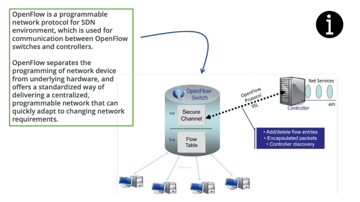
**Role of SDN and NFV**
Moreover, adopting software-defined networking (SDN) and network function virtualization (NFV) further accelerates the realization of the benefits of open networking. SDN separates the control plane from the data plane, providing centralized network management and programmability. NFV virtualizes network functions, allowing for dynamic provisioning and scalability.
A. Use Cases and Real-World Examples:
Data Centers and Cloud Computing: Open networking has gained significant traction in data centers and cloud computing environments. By leveraging open networking principles, organizations can build scalable and flexible data center networks that seamlessly integrate with cloud platforms, enabling efficient data management and resource allocation.
**Separate Control from Data Plane**
Software-Defined Networking (SDN): SDN is an example of open networking principles. By separating the control plane from the data plane, SDN enables centralized network management, automation, and programmability. This approach empowers network administrators to dynamically configure and optimize network resources, improving performance and reducing operational overhead.
B. Key Open Networking Projects:
Open Network Operating System (ONOS): ONOS is a collaborative project that focuses on creating an open-source, carrier-grade SDN (Software-Defined Networking) operating system. It provides a scalable platform for building network applications and services, facilitating innovation and interoperability.
OpenDaylight (ODL): ODL is a modular, extensible, open-source SDN controller platform. It aims to accelerate SDN adoption by providing developers and network operators with a common platform to build and deploy network applications.
FRRouting (FRR): FRR is an open-source IP routing protocol suite that supports various routing protocols, including OSPF, BGP, and IS-IS. It offers a flexible and scalable routing solution, enabling network operators to optimize their routing infrastructure.
The Role of Transformation
Infrastructure: Embrace Transformation:
To undertake an effective SDN data center transformation strategy, we must accept that demands on data center networks come from internal end-users, external customers, and considerable changes in the application architecture. All of these factors put pressure on traditional data center architecture.
Dealing effectively with these demands requires the network domain to become more dynamic, potentially introducing Open Networking and Open Networking solutions. For this to occur, we must embrace digital transformation and the changes it will bring to our infrastructure. Unfortunately, keeping current methods is holding back this transition.
Modern Network Infrastructure:
In modern network infrastructures, as has been the case on the server side for many years, customers demand supply chain diversification regarding hardware and silicon vendors. This diversification reduces the Total Cost of Ownership because businesses can drive better cost savings. In addition, replacing the hardware underneath can be seamless because the software above is standard across both vendors.
Leaf and Spine Architecture:
Further, as architectures streamline and spine leaf architecture increases from the data center to the backbone and the Edge, a typical software architecture across all these environments brings operational simplicity. This perfectly aligns with the broader trend of IT/OT convergence.
Working with Open Source Software
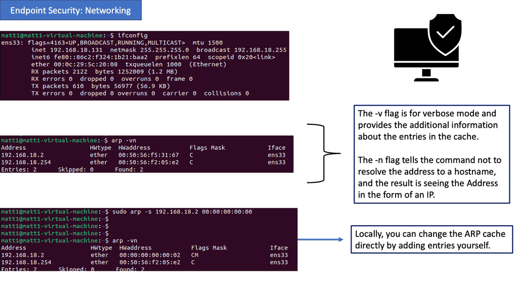
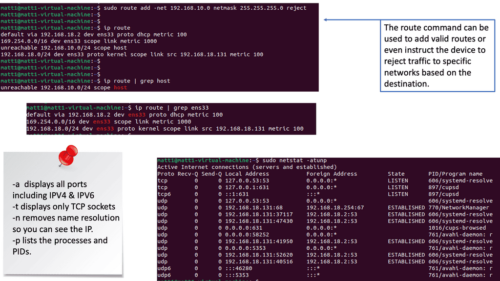
Linux Networking
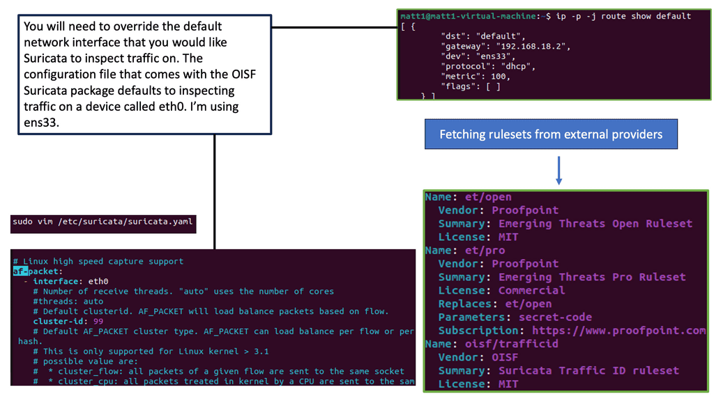
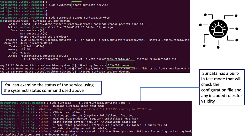
One remarkable aspect of Linux networking is the abundance of powerful tools available for network configuration. From the traditional ifconfig and route commands to the more recent ip command, this section will introduce various tools and their functionalities.
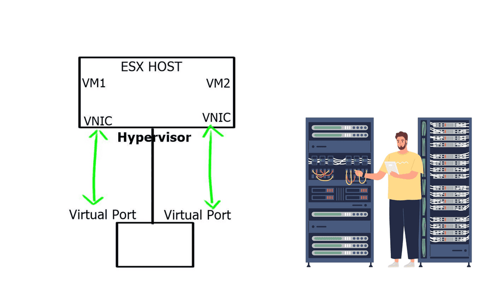
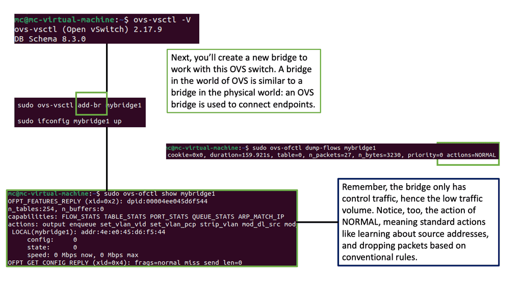
Virtual Switching: Open vSwitch
What is Open vSwitch?
Open vSwitch is a multilayer virtual switch that enables network automation and management in virtualized environments. It bridges virtual machines (VMs) and the physical network, allowing seamless communication and control over network traffic. With its extensible architecture and robust feature set, Open vSwitch offers a flexible and scalable networking solution.
Open vSwitch offers many features, making it a popular choice among network administrators and developers. Some of its key capabilities include:
1. Virtual Network Switching: Open vSwitch can create and manage virtual switches, ports, and bridges, creating complex network topologies within virtualized environments.
2. Flow Control: With Open vSwitch, you can define and control network traffic flow using flow rules. This enables advanced traffic management, filtering, and QoS (Quality of Service) capabilities.
3. Integration with SDN Controllers: Open vSwitch seamlessly integrates with various Software-Defined Networking (SDN) controllers, providing centralized management and control of network resources.
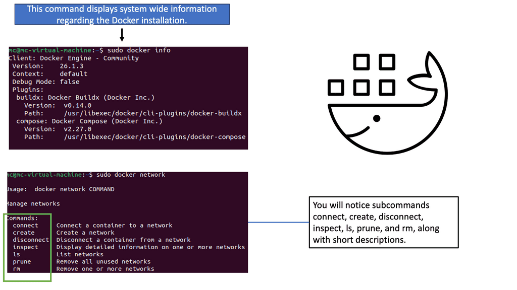
 Containers & Docker Networking
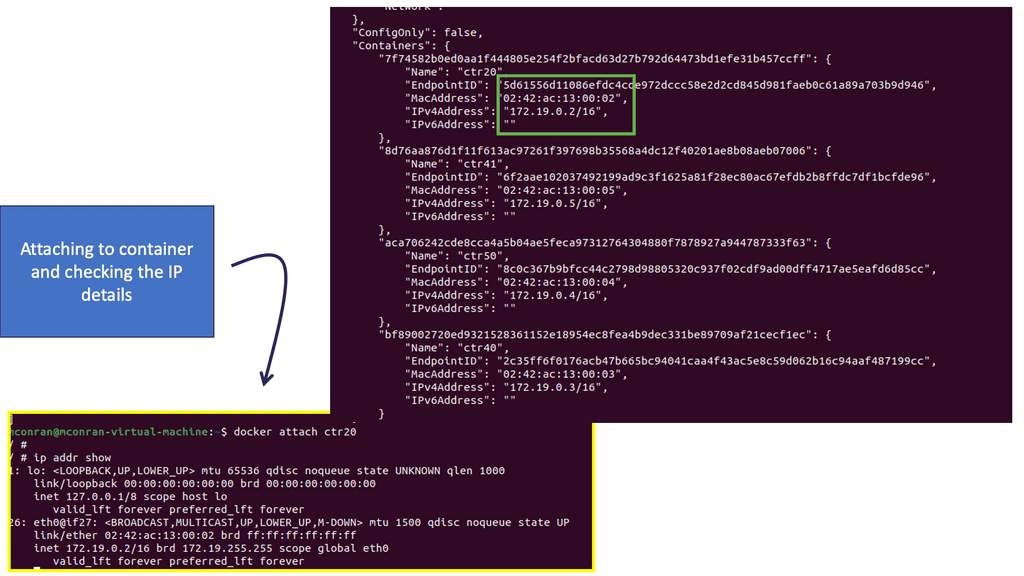
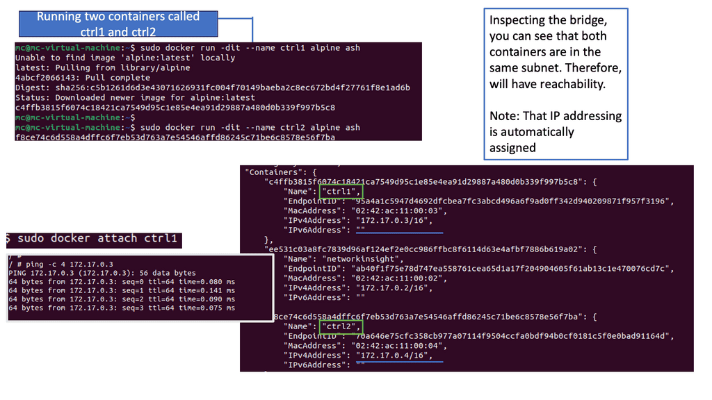
Docker networking revolves around containers, networks, and endpoints. Containers are isolated environments that run applications, while networks act as virtual channels for communication. Endpoints, on the other hand, are unique identifiers attached to containers within a network. Understanding these fundamental concepts is crucial for grasping Docker network connectivity.
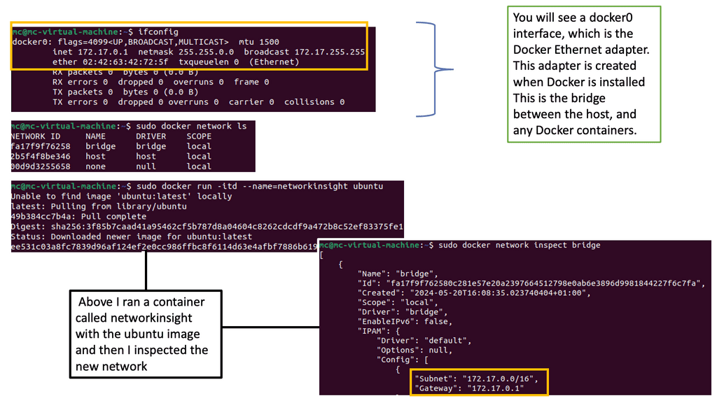
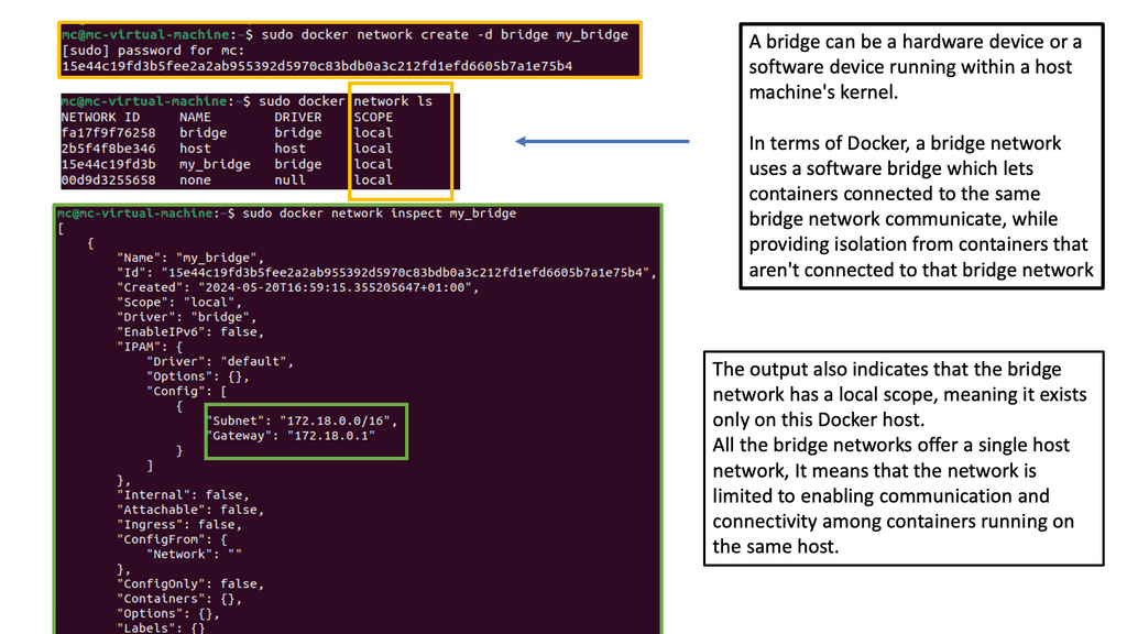
Docker Networking Fundamentals
Docker networking operates on a virtual network that allows containers to communicate securely. Docker creates a bridge network called “docker0” by default and assigns each container a unique IP address. This isolation ensures that containers can run independently without interfering with each other.
The default bridge network in Docker is an internal network that connects containers running on the same host. Containers within this network can communicate with each other using IP addresses. However, containers on different hosts cannot directly communicate over the bridge network.
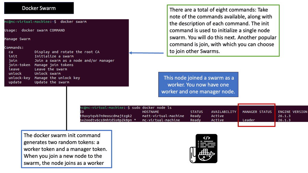
 Orchestrator: Understanding Docker Swarm
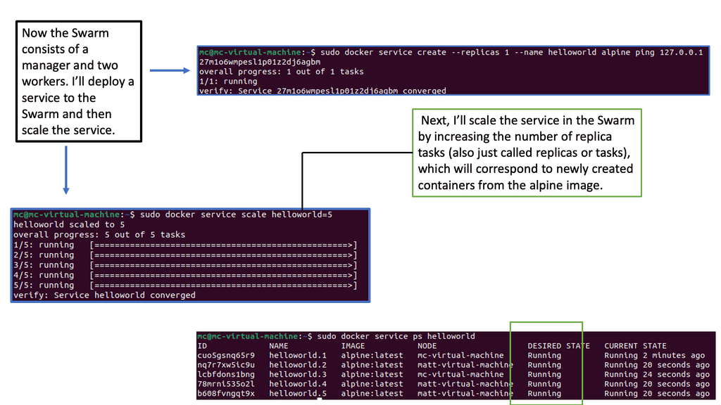
Docker Swarm, a native clustering and orchestration tool for Docker, allows the management of a cluster of Docker nodes as a single virtual system. It provides high availability, scalability, and ease of use for deploying and managing containerized applications. With its intuitive user interface and powerful command-line interface, Docker Swarm simplifies managing container clusters.
Related: For pre-information, you may find the following posts helpful:
Open Networking: The Solutions
Now, let’s look at the evolution of data centers to see how we can achieve this modern infrastructure. To evolve and keep up with current times, you should use technology and your infrastructure as practical tools. You will be able to drive the entire organization to become digital. Of course, the network components will play a key role. Still, the digital transformation process is an enterprise-wide initiative focusing on fabric-wide automation and software-defined networking.
A. Lacking fabric-wide automation:
One central pain point I have seen throughout networking is the necessity to dispense with manual work lacking fabric-wide automation. In addition, it’s common to deploy applications by combining multiple services that run on a distributed set of resources. As a result, configuration and maintenance are much more complex than in the past. You have two options to implement all of this.
Undertaking Manual or Automated Approach
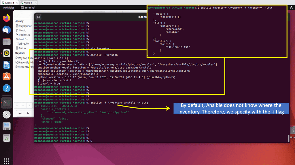
First, you can connect these services by manually spinning up the servers, installing the necessary packages, and SSHing to each one. Alternatively, you can go toward open network solutions with automation, particularly Ansible automation with Ansible Engine or Ansible Tower with automation mesh. As automation best practice, use Ansible variables for flexible playbook creation that can be easily shared and used amongst different environments.
B. Fabric-wide automation and SDN:
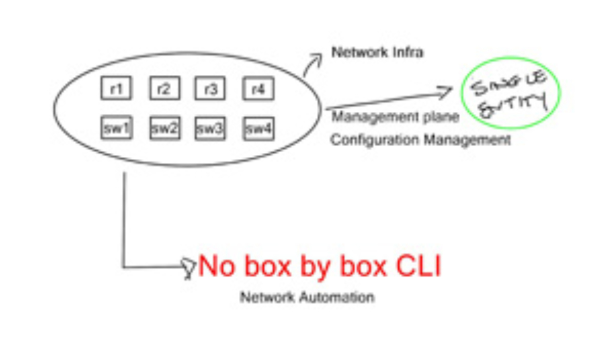
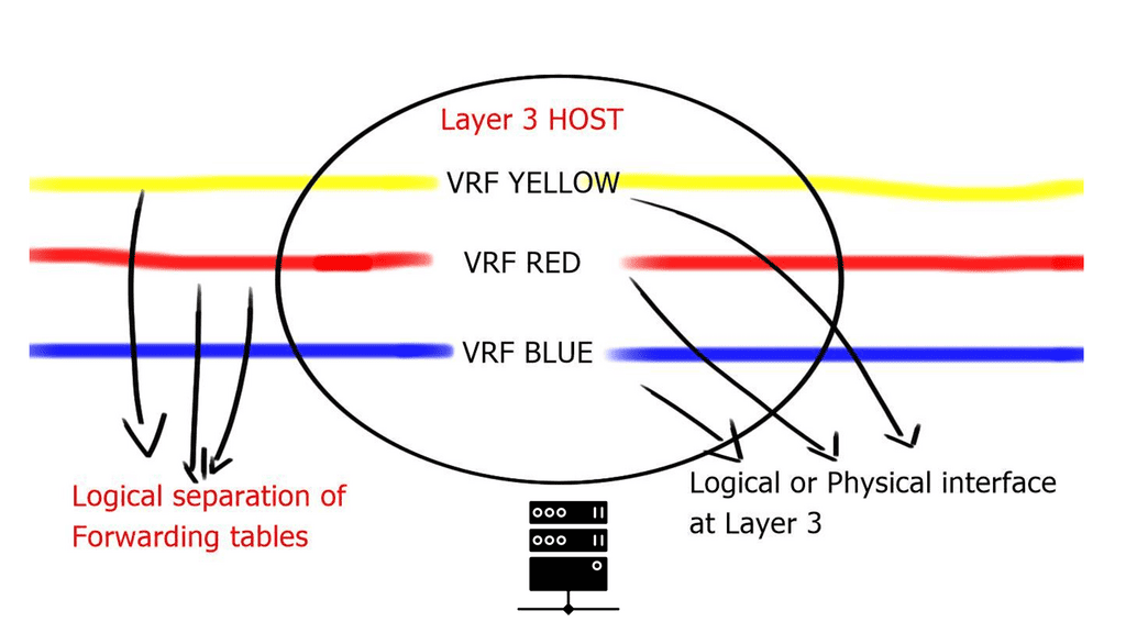
However, deploying a VRF or any technology, such as an anycast gateway, is a dynamic global command in a software-defined environment. We now have fabric-wide automation and can deploy with one touch instead of numerous box-by-box configurations.
We are moving from a box-by-box configuration to the atomic programming of a single entity’s distributing fabric. This allows us to carry out deployments with one configuration point quickly and without human error.
C. Configuration management:
Manipulating configuration files by hand is tedious, error-prone, and time-consuming. Equally, performing pattern matching to make changes to existing files is risky. The manual approach will result in configuration drift, where some servers will drift from the desired state.
Configuration Drift: Configuration drift is caused by inconsistent configuration items across devices, usually due to manual changes and updates and not following the automation path. Ansible architecture can maintain the desired state across various managed assets.
Storing Managed Assets: Managed assets, which can range from distributed firewalls to Linux hosts, are stored in an inventory file, which can be static or dynamic. Dynamic inventories are best suited for a cloud environment where you want to gather host information dynamically. Ansible is all about maintaining the desired state for your domain.
Challenge: The issue of Silos
To date, the networking industry has been controlled by a few vendors. We have dealt with proprietary silos in the data center, campus/enterprise, and service provider environments. The major vendors will continue to provide a vertically integrated lock-in solution for most customers. They will not allow independent, 3rd party network operating system software to run on their silicon.
Required: Modular & Open
Typically, these silos were able to solve the problems of the time. The modern infrastructure needs to be modular, open, and straightforward. Vendors need to allow independent, 3rd party network operating systems to run on their silicon to break from being a vertically integrated lock-in solution. Cisco has started this for the broader industry regarding open networking solutions with the announcement of the Cisco Silicon ONE.
The Rise of Open Networking Solutions
New data center requirements have emerged; therefore, the network infrastructure must break the silos and transform to meet these trending requirements. One can view the network transformation as moving from a static and conservative mindset that results in cost overrun and inefficiencies to a dynamic routed environment that is simple, scalable, secure, and can reach the far edge. For effective network transformation, we need several stages.
**Routed Data Center Design**
Firstly, transition to a routed data center design with a streamlined leaf-spine architecture and a standard operating system across cloud, Edge, and 5G networks. A viable approach would be to do all this with open standards, without proprietary mechanisms. Then, we need good visibility.
**Networking and Visibility**
As part of the transformation, the network is no longer considered a black box that needs to be available and provide connectivity to services. Instead, the network is a source of deep visibility that can aid a large set of use cases: network performance, monitoring, security, and capacity planning, to name a few. However, visibility is often overlooked with an over-focus on connectivity and not looking at the network as a valuable source of information.
**Monitoring at a Flow level**
For efficient network management, we must provide deep visibility for the application at a flow level on any port and device type. You would deploy a redundant monitoring network if you want something comparable today. Such a network would consist of probes, packet brokers, and tools to process the packet for metadata.
**Packet Brokers: Traditional Tooling**
Traditional network monitoring tools like packet brokers require life cycle management. A more viable solution would integrate network visibility into the fabric and would not need many components. This would enable us to do more with the data and aid in agility for ongoing network operations.
Note: Observability: Detecting the unknown
There will always be some requirement for application optimization or a security breach, where visibility can help you quickly resolve these issues. Monitoring is used to detect known problems and is only valid with pre-defined dashboards that show a problem you have seen before, such as capacity reaching its limit.
On the other hand, we have the practices of Observability that can detect unknown situations and are used to aid those in getting to the root cause of any problem, known or unknown:
Example Visibility Technology: sFlow
What is sFlow?
sFlow is a network monitoring technology that allows for real-time, granular network traffic analysis. By sampling packets at high speeds, sFlow provides a comprehensive view of network behavior, capturing key data such as source and destination addresses, port numbers, and traffic volumes. This invaluable information serves as the foundation for network optimization and security.

Evolution of the Data Center
**Several Important Design Phases**
We are transitioning, and the data center has undergone several design phases. Initially, we started with layer 2 silos, suitable for the north-to-south traffic flows. However, layer 2 designs hindered east-west communication traffic flows of modern applications and restricted agility, which led to a push to break network boundaries.
**Layer 3 Routing & Overlay Networking**
Hence, routing at the top of the rack (ToR) with overlays between ToR is moved to drive inter-application communication. This is the most efficient approach, which can be accomplished in several ways.
The demand for leaf and spine “clos” started in the data center and spread to other environments. A closed network is a type of non-blocking, multistage switching architecture.
This network design extends from the central/backend data center to the micro data centers at the EdgeEdge. Various parts of the edge network, PoPs, central offices, and packet core have all been transformed into leaf and spine “clos” designs.
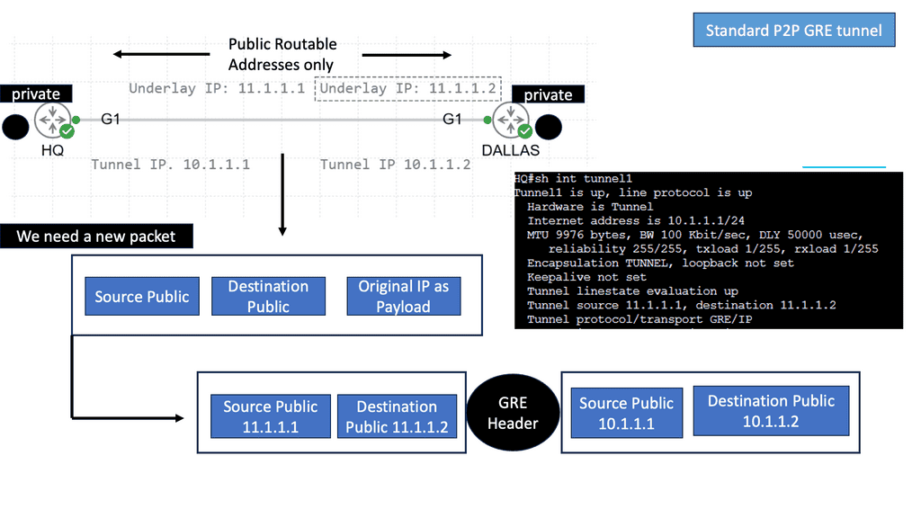
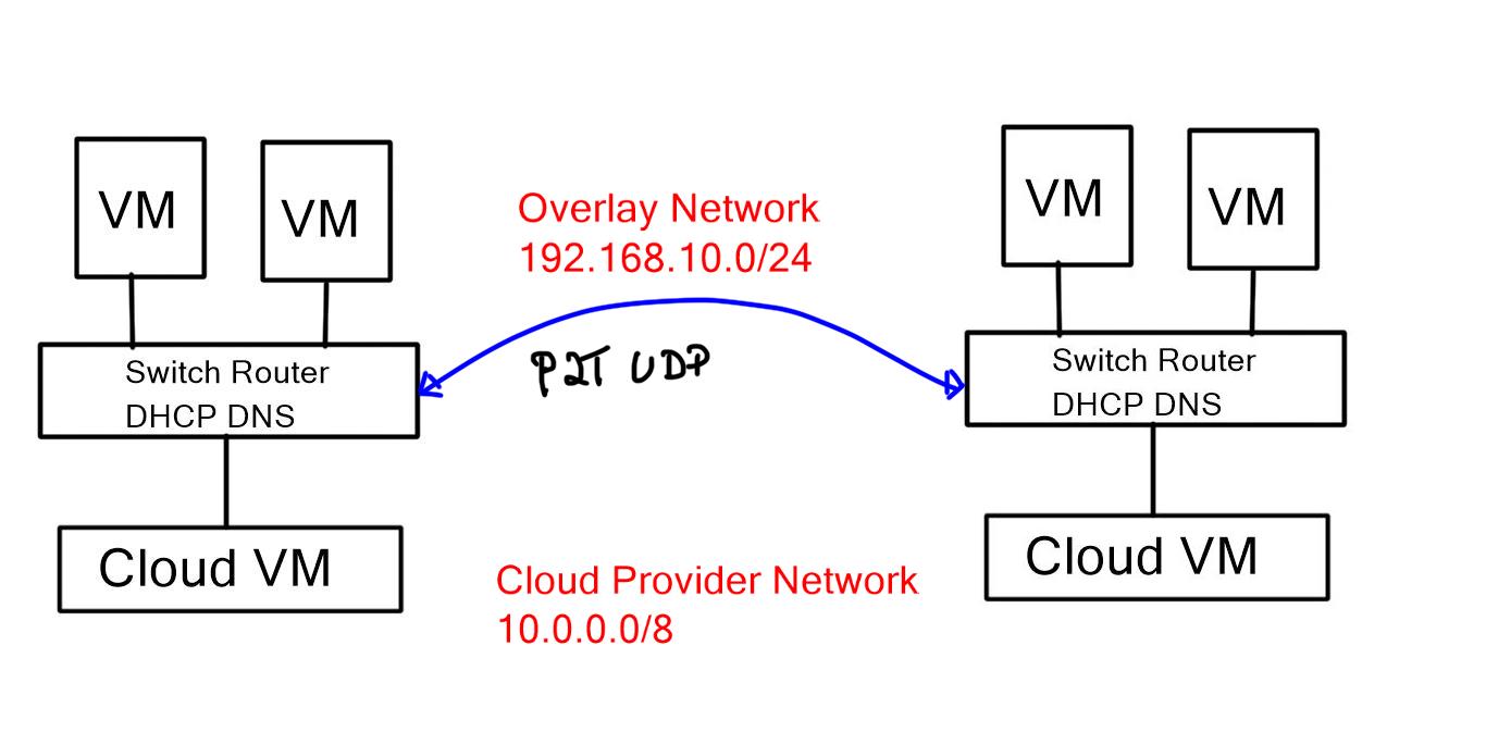
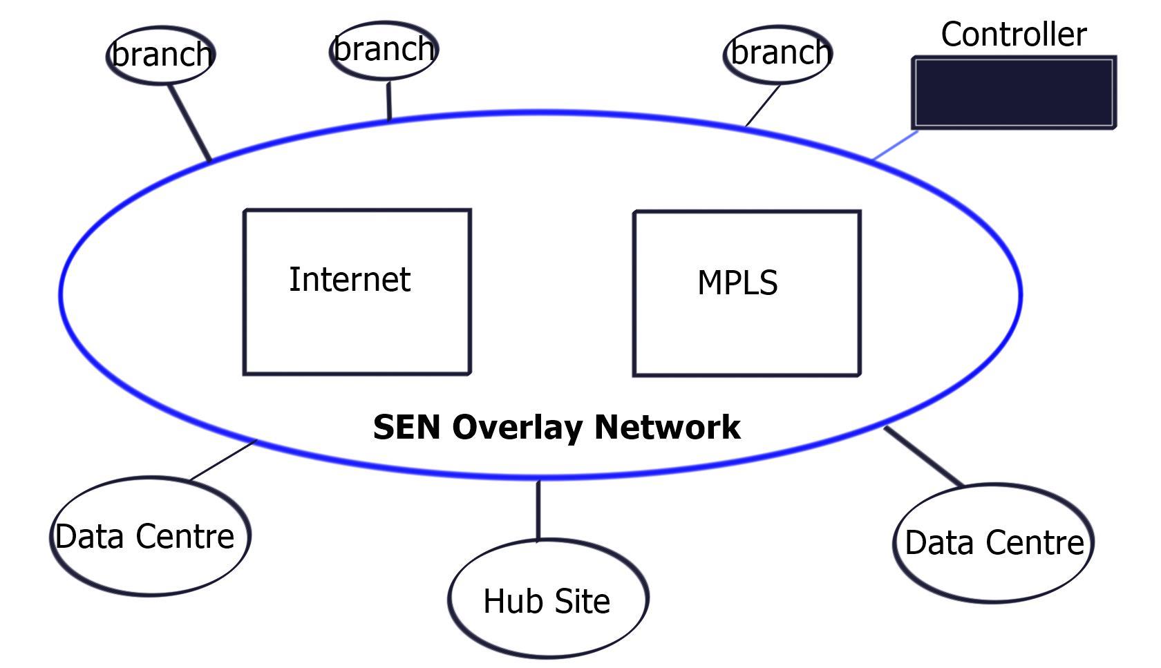
The network overlay
When increasing agility, building a complete network overlay is common to all software-defined technologies. An overlay is a solution abstracted from the underlying physical infrastructure. This means separating and disaggregating the customer applications or services from the network infrastructure. Think of it as a sandbox or private network for each application on an existing network.
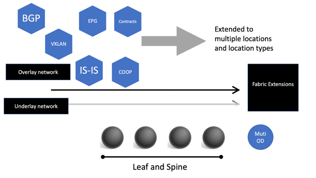
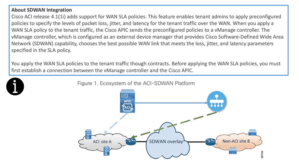
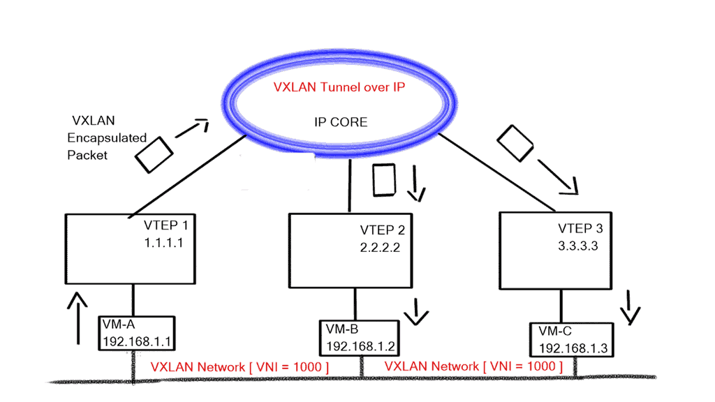
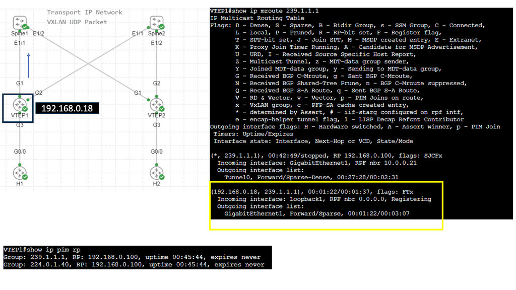
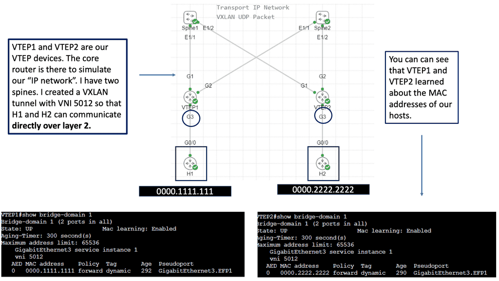
Example: Overlay Networking with VXLAN
The network overlay is more often created with VXLAN. The Cisco ACI uses an ACI network of VXLAN for the overlay, and the underlay is a combination of BGP and IS-IS. The overlay abstracts a lot of complexity, and Layer 2 and 3 traffic separation is done with a VXLAN network identifier (VNI).
The VXLAN overlay
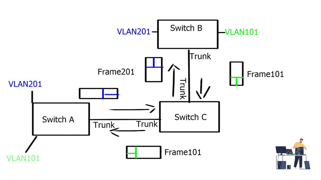
VXLAN uses a 24-bit network segment ID, called a VXLAN network identifier (VNI), for identification. This is much larger than the 12 bits used for traditional VLAN identification. The VNI is just a fancy name for a VLAN ID, but it now supports up to 16 Million VXLAN segments.
Challenge: Traditional VLANs
This is considerably more than the traditional 4094-supported endpoints with VLANs. Not only does this provide more hosts, but it also enables better network isolation capabilities, with many little VXLAN segments instead of one large VLAN domain.
Required: Better Isolation and Scalability
The VXLAN network has become the de facto overlay protocol and brings many advantages to network architecture regarding flexibility, isolation, and scalability. VXLAN effectively implements an Ethernet segment that virtualizes a thick Ethernet cable.
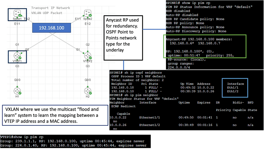
Use Case: – **VXLAN Flood and Learn**
Flood and learn is a crucial mechanism within VXLAN that enables the dynamic discovery of VXLAN tunnels and associated endpoints. When a VXLAN packet reaches a switch, and the destination MAC address is unknown, the switch utilizes flood and learns to broadcast the packet to all its VXLAN tunnels. The receiving tunnel endpoints then examine the packet, learn the source MAC address, and update their forwarding tables accordingly.

Traditional policy deployment
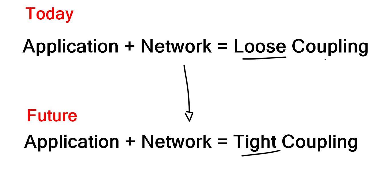
Traditionally, deploying an application to the network involves propagating the policy to work through the entire infrastructure. Why? Because the network acts as an underlay, segmentation rules configured on the underlay are needed to separate different applications and services.
This creates a rigid architecture that cannot react quickly and adapt to changes, therefore lacking agility. The applications and the physical network are tightly coupled. Now, we can have a policy in the overlay network with proper segmentation per customer.
1. Virtual Networking & ToR switches
Virtual networks and those built with VXLAN are built from servers or ToR switches. Either way, the underlying network transports the traffic and doesn’t need to be configured to accommodate the customer application. Everything, including the policy, is done in the overlay network, which is most efficient when done in a fully distributed manner.
2. Flexibility of Overlay Networking
Now, application and service deployment occurs without touching the physical infrastructure. For example, if you need to have Layer 2 or Layer 3 paths across the data center network, you don’t need to tweak a VLAN or change routing protocols. Instead, you add a VXLAN overlay network. This approach removes the tight coupling between the application and network, creating increased agility and simplicity in deploying applications and services.
**Key Point: Extending from the data center**
Edge computing creates a fundamental disruption among the business infrastructure teams. We no longer have the framework where IT only looks at the backend software, such as Office365, and OT looks at the routing and switching product-centric elements. There is convergence.
Therefore, you need many open APIs. The edge computing paradigm brings processing closer to the end devices, reducing latency and improving the end-user experience. It would help if you had a network that could work with this model to support this. Having different siloed solutions does not work.
3. Required: Common software architecture
So the data center design went from the layer 2 silo to the leaf and spine architecture with routing to the ToR. However, there is another missing piece. We need a standard operating software architecture across all the domains and location types for switching and routing to reduce operating costs. The problem remains that even on one site, there can be several different operating systems.
I have experienced the operational challenge of having many Cisco operating systems on one site through recent consultancy engagements. For example, I had an IOS XR for service provider product lines, IOS XE for enterprise, and NS OX for the data center, all on a single site.
4. Challenge: The traditional integrated vendor
Traditionally, networking products were a combination of hardware and software that had to be purchased as an integrated solution. Conversely, open networking disaggregates hardware from software, allowing IT to mix and match at will.
With Open Networking, we are not reinventing how packets are forwarded or routers communicate. With Open Networking solutions, you are never alone and never the only vendor. The value of software-defined networking and Open Networking is doing as much as possible in software so you don’t depend on delivering new features from a new generation of hardware. If you want a new part, it’s quickly implemented in software without swapping the hardware or upgrading line cards.
5. Required: Move intelligence to software.
You want to move as much intelligence as possible into software, thus removing the intelligence from the physical layer. You don’t want to build in hardware features; you want to use the software to provide the new features. This is a critical philosophy and is the essence of Open Networking. Software becomes the central point of intelligence, not the hardware; this intelligence is delivered fabric-wide.
As we have seen with the rise of SASE, customers gain more agility as they can move from generation to generation of services without hardware dependency and without the operational costs of constantly swapping out the hardware.
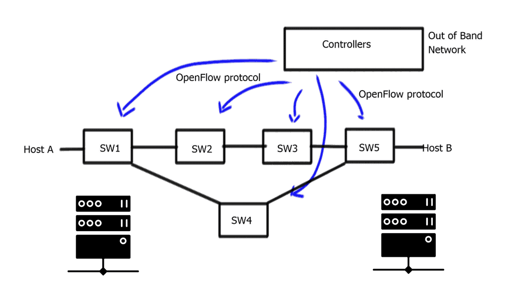
**SDN Network Design Options**
We have both controller and controllerless options. With a controllerless solution, setup is faster, agility increases, and robustness in single-point-of-failure is provided, particularly for out-of-band management, i.e., connecting all the controllers.
SDN Controllerless & Controller architecture:
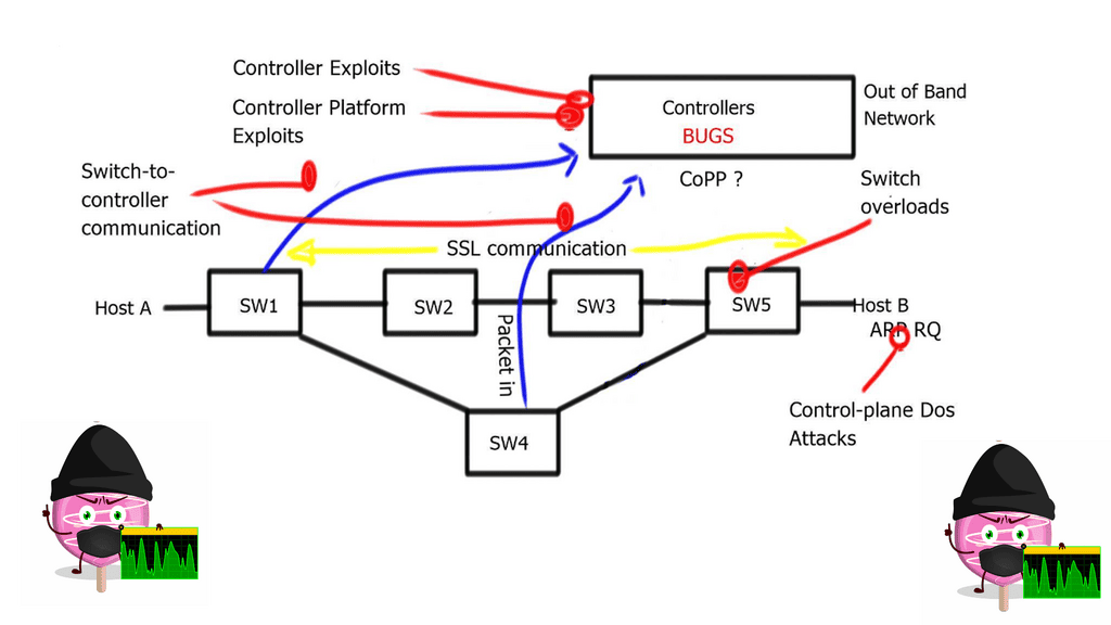
A controllerless architecture is more self-healing; anything in the overlay network is also part of the control plane resilience. An SDN controller or controller cluster may add complexity and impede resiliency. Since the network depends on them for operation, they become a single point of failure and can impact network performance. The intelligence kept in a controller can be a point of attack.
So, there are workarounds where the data plane can continue forward without an SDN controller but always avoid a single point of failure or complex ways to have a quorum in a control-based architecture.
We have two main types of automation to consider: day 0 and days 1-2. First and foremost, day 0 automation simplifies and reduces human error when building the infrastructure. Days 1-2 touch the customer more. This may include installing services quickly, e.g., VRF configuration and building Automation into the fabric.
A. Day 0 automation
As I said, day 0 automation builds basic infrastructures, such as routing protocols and connection information. These stages need to be carried out before installing VLANs or services. Typical tools that software-defined networking uses are Ansible or your internal applications to orchestrate the building of the network.
Fabric Automation Tools
These are known as fabric automation tools. Once the tools discover the switches, the devices are connected in a particular way, and the fabric network is built without human intervention. It simplifies traditional automation, which is helpful in day 0 automation environments.
- Configuration Management: Ansible is a configuration management tool that can help alleviate manual challenges. Ansible replaces the need for an operator to tune configuration files manually and does an excellent job in application deployment and orchestrating multi-deployment scenarios.
- Pre-deployed infrastructure: Ansible does not deploy the infrastructure; you could use other solutions like Terraform that are best suited for this. Terraform is infrastructure as a code tool. Ansible is often described as a configuration management tool and is typically mentioned along the same lines as Puppet, Chef, and Salt. However, there is a considerable difference in how they operate.
Most notably, the installation of agents. Ansible automation is relatively easy to install as it is agentless. The Ansible architecture can be used in large environments with Ansible Tower using the execution environment and automation mesh. I have recently encountered an automation mesh, a powerful overlay feature that enables automation closer to the network’s edge.
Ansible ensures that the managed asset’s current state meets the desired state. It is all about state management. It does this with Ansible Playbooks, more specifically, YAML playbooks. A playbook is a term Ansible uses for a configuration management script that ensures the desired state is met. Essentially, playbooks are Ansible’s configuration management scripts.
B. Day 1-2 automation
With day 1-2 automation, SDN does two things.
Firstly, installing or provisioning services automatically across the fabric is possible. With one command, human error is eliminated. The fabric synchronizes the policies across the entire network. It automates and disperses the provisioning operations across all devices. This level of automation is not classical, as this strategy is built into the SDN infrastructure.
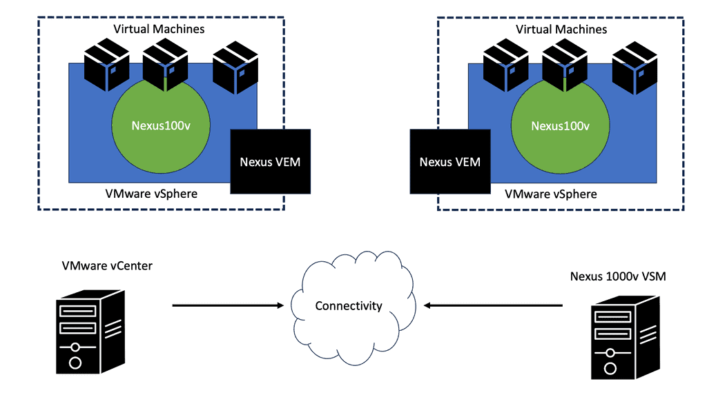
Secondly, it integrates network operations and services with virtualization infrastructure managers such as OpenStack, VCenter, OpenDaylight, or, at an advanced level, OpenShift networking SDN. How does the network adapt to the instantiation of new workloads via the systems? The network admin should not even be in the loop if, for example, a new virtual machine (VM) is created.
A signal that a VM with specific configurations should be created should be propagated to all fabric elements. When the virtualization infrastructure managers provide a new service, you shouldn’t need to touch the network. This represents the ultimate agility as you remove the network components.