6LoWPAN Range

6LoWPAN Range

In the rapidly evolving world of Internet of Things (IoT), one technology that has gained significant attention is 6LoWPAN. Standing for IPv6 over Low-Power Wireless Personal Area Network, 6LoWPAN provides a revolutionary solution for extending the range of IoT devices while maintaining efficiency. This blogpost delves into the various aspects of 6LoWPAN and its impressive range capabilities.

6LoWPAN is a wireless communication protocol that enables the transmission of IPv6 packets over low-power wireless networks. It efficiently compresses IPv6 packets to fit within the constraints of low-power devices, making it ideal for IoT applications. By leveraging existing wireless technologies, such as IEEE 802.15.4, 6LoWPAN offers seamless integration and compatibility with a wide range of devices.

Extending the Range of IoT Devices: One of the key advantages of 6LoWPAN is its ability to extend the range of IoT devices. By utilizing mesh networking, where devices act as routers to relay data, 6LoWPAN creates a robust network infrastructure. This enables devices to communicate with each other even when they are located far apart, effectively expanding the range of IoT deployments.

Overcoming Range Limitations: While 6LoWPAN offers impressive range capabilities, it is important to consider potential limitations. Factors such as physical obstacles, signal interference, and power constraints can impact the effective range of 6LoWPAN networks. However, by strategically placing routers and optimizing network configurations, these limitations can be mitigated, allowing for reliable and extended range connectivity.

The range extension capabilities of 6LoWPAN open up a world of possibilities for IoT applications. Smart cities, industrial automation, and agricultural monitoring are just a few examples of domains that can greatly benefit from the extended range offered by 6LoWPAN. By connecting devices across vast areas, valuable data can be collected, analyzed, and utilized to enhance efficiency and improve decision-making processes.

6LoWPAN is a game-changer in the realm of IoT connectivity, offering an extensive range that revolutionizes the way devices communicate and interact. With its ability to overcome range limitations and its wide range of real-world applications, 6LoWPAN paves the way for innovative IoT deployments. As the IoT landscape continues to evolve, 6LoWPAN stands as a powerful tool in creating a connected world.

Highlights: 6LoWPAN Range

Wireless Communication Protocol

– 6LoWPAN, at its core, is a wireless communication protocol that enables the transmission of IPv6 packets over low-power and constrained networks. It leverages the power of IPv6 to provide unique addresses to each device, facilitating seamless connectivity and interoperability. With its efficient compression techniques, 6LoWPAN optimizes data transmission, making it suitable for resource-constrained devices and networks.

– The adoption of 6LoWPAN brings forth a multitude of benefits. Firstly, it enables the integration of a vast number of devices into the IoT ecosystem, creating a rich network of interconnected systems. Additionally, 6LoWPAN’s low-power characteristics make it ideal for battery-operated devices, extending their lifespan. Moreover, its compatibility with IPv6 ensures scalability and future-proofing, allowing for easy integration with existing infrastructure.

– 6LoWPAN finds its applications in various domains, ranging from smart homes and industrial automation to healthcare and agriculture. In smart homes, 6LoWPAN enables seamless communication between different devices, enabling automation and enhanced user experiences. Similarly, in industrial automation, 6LoWPAN plays a vital role in connecting sensors and actuators, enabling real-time monitoring and control. In healthcare, 6LoWPAN facilitates the deployment of wearable devices and remote patient monitoring systems, improving healthcare outcomes.

– While 6LoWPAN has immense potential, it also faces certain challenges. The limited bandwidth and range of low-power networks can pose constraints on data transmission and coverage. Interoperability between different 6LoWPAN implementations also needs to be addressed to ensure seamless communication across various systems. However, ongoing research and development efforts aim to overcome these challenges and further enhance the capabilities of 6LoWPAN.

Key Point: IPv6 and IoT

An IPv6 protocol called 6LoWPAN extends IPv6 to low-power personal area networks. Wireless Personal Area Networks, or WPANs, are the target of this protocol. WPANs are wireless personal area networks (PANs) that connect devices in a person’s workspace. IPv6 is supported by 6LoWPAN. IPv6, or Internet Protocol Version 6, enables communication over the Internet. Besides providing a large number of addresses, it is also faster and more reliable.

6LoWPAN was initially designed to replace conventional methods of transmitting information. However, due to its limited processing capabilities, IPv6 is not efficient. It only enables smaller devices with minimal processing capabilities to communicate. Furthermore, it has a low bit rate, a short range, and a memory requirement. Edge routers and sensor nodes make up the system. Almost any IoT device, such as streetlights with LEDs, can now connect to the network and transmit data, such as streetlights with LEDs, for instance.

6LoWPAN’s key Features and Applications

One of 6LoWPAN’s key features is its ability to compress IPv6 packets, reducing their size and conserving valuable network resources. This compression technique allows IoT devices with limited resources, such as low-power sensors, to operate efficiently within the network. Additionally, 6LoWPAN supports mesh networking, enabling devices to relay data for improved coverage and network resilience. With its lightweight nature and adaptability, 6LoWPAN provides a cost-effective and scalable solution for IoT connectivity.

6LoWPAN’s applications are vast and diverse. Its low power consumption and support for IPv6 make it particularly suitable for smart home automation systems, where numerous IoT devices need to communicate with each other seamlessly. Furthermore, 6LoWPAN finds applications in industrial settings, enabling efficient monitoring and control of various processes. From healthcare and agriculture to transportation and environmental monitoring, 6LoWPAN empowers many IoT applications.

**The Role of Connectivity Requirements**

Consistent connectivity with Internet of Things access technologies locally among IoT things and to remote cloud or on-premise IoT platforms requires having the correct type of network infrastructure that suits the characteristics of IoT devices. It is expensive, and we are seeing short-range Low-Power and long-range Low-Power networks deployment in the IoT world. 6LoWPAN IoT, IPv6, and 6LoWPAN range compression and IPv6 fragmentation techniques enable IP on even the smallest devices, offering direct IP addressing and a NAT-free world.

**New Design Approaches**

Depending on device requirements and characteristics, the Internet of Things networking design might consist of several “type” centric design approaches. For example, we can select thing-centric, gateway-centric, smartphone-centric, and cloud-centric designs based on IoT device requirements.

If slow and expensive satellite links result in a thing-centric design, some processing may need to be performed locally. Other device types require local gateway support, while others communicate directly to the IoT platform.

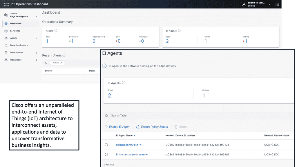
Example Product: Cisco IoT Operations Dashboard

### Introduction to Cisco IoT Operations Dashboard

In an era where the Internet of Things (IoT) is revolutionizing industries, the Cisco IoT Operations Dashboard stands out as a crucial tool for managing and optimizing IoT deployments. This powerful platform offers real-time insights, enhanced security, and streamlined operations, making it indispensable for businesses looking to harness the full potential of their IoT solutions.

### Real-Time Monitoring and Insights

One of the standout features of the Cisco IoT Operations Dashboard is its ability to provide real-time monitoring and insights. With this tool, businesses can keep an eye on their IoT devices and networks around the clock. This continuous monitoring allows for immediate detection of issues, enabling swift responses that minimize downtime and maintain operational efficiency. The dashboard presents data in an intuitive and accessible format, making it easier for teams to stay informed and make data-driven decisions.

### Enhanced Security for IoT Deployments

Security is a paramount concern in the world of IoT, where devices are often spread across various locations and networks. The Cisco IoT Operations Dashboard addresses this challenge by offering robust security features. It includes advanced threat detection and response capabilities, ensuring that any potential vulnerabilities are quickly identified and mitigated. This proactive approach to security helps protect sensitive data and maintain the integrity of IoT systems, giving businesses peace of mind.

### Streamlined Operations and Management

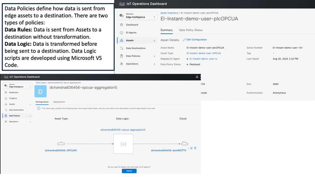
Managing a large number of IoT devices can be a daunting task. The Cisco IoT Operations Dashboard simplifies this process by providing a centralized platform for device management. Whether it’s onboarding new devices, updating software, or configuring settings, the dashboard makes these tasks straightforward and efficient. This streamlining of operations not only saves time but also reduces the risk of errors, leading to smoother and more reliable IoT deployments.

### Scalability and Flexibility

As businesses grow and their IoT needs evolve, scalability becomes a critical factor. The Cisco IoT Operations Dashboard is designed with scalability in mind, allowing companies to easily expand their IoT deployments without compromising performance. Additionally, the platform’s flexibility means it can be tailored to meet the specific needs of various industries, from manufacturing to healthcare. This adaptability ensures that businesses can continue to leverage the dashboard’s capabilities as their IoT initiatives mature.

Before you proceed, you may find the following helpful post for pre-information:

  1. Internet of Things Theory
  2. IPv6 Host Exposure
  3. Technology Insights for Microsegmentation


6LoWPAN Range

The two dominant modern network architectures are cloud computing and the Internet of Things (IoT), sometimes called fog computing. The future of the Internet will involve many IoT objects that use standard communications architectures to provide services to end users.

Tens of billions of such devices are envisioned to be interconnected. This will introduce interactions between the physical world and computing, digital content, analysis, applications, and services. The resulting networking paradigm is called the Internet of Things (IoT).

Factors Influencing 6LoWPAN Range:

a) Transmission Power: The transmission power of a 6LoWPAN device plays a significant role in determining its range. Higher transmission power allows devices to communicate over considerable distances and consumes more energy, impacting battery life.

b) Environment: The physical environment in which 6LoWPAN devices operate can affect their effective range. Obstacles such as walls, buildings, and interference from other wireless devices can attenuate the signal strength, reducing the range.

c) Antenna Design: The design and placement of antennas in 6LoWPAN devices can impact their range. Optimized antenna designs can enhance signal propagation and improve the network’s overall range.

Extending 6LoWPAN Range:

While 6LoWPAN networks have a limited range by design, there are several techniques to extend their coverage:

a) Mesh Topology: Implementing a mesh topology allows devices to relay messages to each other, expanding the network’s coverage. By relaying packets, devices can communicate beyond their direct range, effectively extending the overall range of the network.

b) Signal Amplification: Using signal amplification techniques, such as increasing the transmission power or employing external amplifiers, can boost the signal strength and extend the range of 6LoWPAN devices.

c) Repeater Nodes: Deploying additional repeater nodes within the network can help bridge communication gaps and extend the range. These nodes receive and retransmit packets, allowing devices to communicate with each other even when they are out of direct range.

Considerations for 6LoWPAN Range Optimization:

To optimize the range of a 6LoWPAN network, it is essential to consider the following factors:

a) Power Consumption: Increasing the transmission power to extend the range can lead to higher power consumption. Balancing range and power efficiency is essential to ensure optimal device performance and battery life.

b) Network Density: The number of devices within a 6LoWPAN network can impact the overall range. Higher device density may require additional repeater nodes or signal amplification to maintain effective communication across the network.

c) Environmental Constraints: Understanding the physical environment and any potential obstacles is crucial for optimizing the range of a 6LoWPAN network. Conducting site surveys and considering the placement of devices and repeaters can significantly enhance network coverage.

**6LoWPAN Range: IoT Networking**

The Internet of Things networking design is device-type-driven and depends on the devices’ memory and processing power. These devices drive a new network paradigm, a paradigm no longer well-defined with boundaries. It is dynamic and extended to the edge where IoT devices are located. It is no longer static, as some of these devices and sensors move and sleep as required. 

There are many factors to consider when selecting wireless infrastructure. It would be best if you took into consideration

  • Range,
  • Power consumption and battery life,
  • Data requirements,
  • Security, and
  • Endpoint and operational costs of IoT devices.

These characteristics will dictate the type of network and may even result in a combination of technologies.

Similar to how applications drive the network design in a non-IoT network, the IoT device and the application it serves drive the network design in the IoT atmosphere. 

Cellular connectivity is the most widely deployed network. Still, the Internet of Things networking is expensive per node and has poor battery life as there will be way more IoT endpoints than cellular phones. New types of networks are needed.

Cellular networks are not agile enough, and provisioning takes ages. Smart IoT devices require more signaling than what traditional cellular networks are used to carrying. Devices require bi-directional signaling between each other or remote servers, which needs to be reliable. Reach is also a challenge when connecting far-flung IoT devices. 

  • Two types of networks are commonly deployed in the IoT world: short-range Low-Power and long-range Low-Power networks.

Internet of Things networking: Short-range low-power

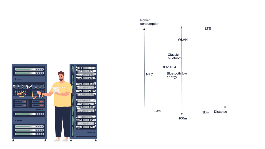
New devices, data types, and traffic profiles result in new access networks for the “last 100 meters of connectivity”. As a result, we see the introduction of many different types of technologies at this layer – Z-Wave, ZigBee, Bluetooth, IEEE 802.15.46LoWPAN Range, RFID, Edge, and Near Field Communication ( NFC ).

Devices that live on short-range networks have particular characteristics:

  1. Low cost.
  2. With low power consumption, energy is potentially harvested from another power source.
  3. It is short-range and has the potential for extension with a router or repeater.

These networks usually offer a range of around 10 – 100 meters, 5 – 10 years of battery life, low bandwidth requirements, and low endpoint costs. Potentially consist of 100 – 150 adjacent devices, usually deployed in the smart home/office space.

The topologies include point-to-point, star, and mesh. A gateway device usually acts as a bridge or interface linking the outside network to the internal short-range network. A gateway could be as simple as a smartphone or mobile device. For example, a smartphone could be the temporary gateway when it approaches the sensor or device in an access control system. 

Short-range low-power technologies

    • Bluetooth low energy ( BLE ) or Bluetooth smart

Bluetooth Smart has the most extensive ecosystem with widespread smartphone integration. It fits into many sectors, including home and building, health and fitness, security, and remote control. Most smart devices, including adult toys, use Bluetooth technology.

That being said, when using Bluetooth technology, there is always a risk of being targeted by hackers. In recent years, more and more people have started to worry about Bluetooth toys getting hacked.

Nonetheless, as long as people take necessary precautions, their chances of getting hacked are relatively low. Moreover, Bluetooth has the potential for less power consumption than IEEE 802.15.4 and looks strong as a leader in the last 100 meters.

Recently, with Bluetooth 4.2, BLE devices can directly access the Internet with 6LoWPAN IoT. It has a similar range to Classic Bluetooth and additional functionality to reduce power consumption. In addition, BLE is reliable because of its support for adaptive frequency hopping ( AFH ). 

The data rate and range depict whether you can use BLE or not. If your application sends small chunks of data, you’re fine, but if you want to send large file transfers, you should look for an alternative technology. The range is suited for 50 – 150 meters, and the max data rate is 1 Mbps.

6LoWPAN Range

6LoWPAN IoT

6LoWPAN Range: IEEE 802.15.4 wireless

IEEE 802.15.4 will be the niche wireless technology of the future. It already has an established home and building automation base—the IEEE 802.15.4 market targets small battery-powered devices that wake up for some time and return to sleep. IEEE 802.15.4 consists of low-bit, low-power, and low-cost endpoints. The main emphasis is on low-cost communication between nearby devices.

It is only the physical and MAC layers and doesn’t provide anything on top of that. This is where, for example, ZigBee and 6LoWPAN IoT come into play. Specifications such as 6LoWPAN IoT and ZigBee are built on the IEEE 802.15.4 standard and add additional functionality to the upper layers. 15.4 has simple addressing with no routing. It has star and peer-to-peer topologies. Mesh topologies are supported, but you must add layers not defined by default in IEEE.

ZigBee

ZigBee is suited for applications with infrequent data transfers of around 250 kbps and a low range between 10 – 100m. It’s a very low-cost and straightforward network compared to Bluetooth and Wi-Fi. However, it is a proprietary solution, and there is no ZigBee support for the Linux kernel, resulting in a significant performance hit for userspace interaction.

This is one of the reasons why the 6LoWPAN range would be a better option, which also runs on top of IEEE 802.15.4. NFC ( Near Field Communication ) has low power but is very short-range, enabling a simple 2-way interaction. An example would be a contactless payment transaction. WLAN (Wi-Fi) has a large ecosystem but high power consumption.

Low-power wide-area network (LPWAN) or low-power network (LPN)

BLE, ZigBee, and Wi-Fi are not designed for long-range performance, and traditional Cellular networks are costly and consume much power. On the other hand, power networks are a class of wireless networks consisting of constrained devices that process power, memory, and battery life. The battery’s length depends on the power consumption, and low power consumption enables devices to last up to 10 years on a battery.

Receiver Sensitivity

When a device transmits a signal, it needs energy from the receiving side to detect it. As always, a certain amount of power is lost during transmission. One of the reasons for LPWAN’s long reach is high receiver sensitivity. Receiver sensitivities in LPWAN operate at -130 dBm; typically, in other wireless technologies, this would be 90 – 110 dBm. Receiver sensitivity operating at -130 can detect 10,000 times quicker than at -90.

It offers long-range communication at a meager bit rate. LPWAN has a much longer range than Wi-Fi and is more cost-effective than cellular networks. Each node can be up to 10 km from the gateway. Data rates are low. Usually, only 20 – 256 bytes per message are sent daily.

These networks are optimized for specific types of data transfers consisting of small, intermittent data blocks. Not all IoT applications transmit large amounts of data. For example, a parking garage sensor only transmits when a parking space is occupied or empty. Devices within these networks are generally cheap at £5 per module and optimized for low throughput.

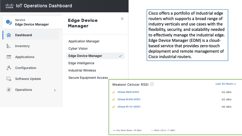
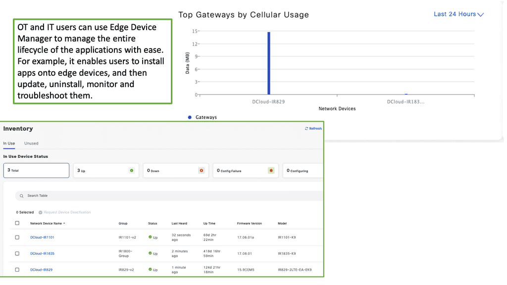
Example Product: Cisco Edge Device Manager

**Understanding Cisco Edge Device Manager**

Cisco Edge Device Manager is a robust solution that provides centralized management for edge devices connected to your network. It offers a user-friendly interface that allows administrators to monitor, configure, and troubleshoot devices remotely. This means less time spent on manual configurations and more time focusing on strategic initiatives. Key features include real-time monitoring, automated updates, and secure connectivity, all designed to ensure your edge devices operate efficiently and securely.

**Seamless Integration with Cisco IoT Operations Dashboard**

One of the standout features of Cisco Edge Device Manager is its seamless integration with the Cisco IoT Operations Dashboard. This integration allows for a holistic view of your IoT ecosystem, providing valuable insights into device performance and network health. The dashboard offers advanced analytics, alerting systems, and reporting tools that help you make data-driven decisions. By combining these two powerful tools, businesses can achieve greater operational efficiency and improved device management.

**Key Benefits of Using Cisco Edge Device Manager**

1. **Enhanced Visibility**: Gain real-time insights into the status and performance of your edge devices, allowing for proactive management and swift issue resolution.

2. **Increased Security**: With built-in security features, Cisco Edge Device Manager ensures that your devices and data remain protected from cyber threats.

3. **Scalability**: As your IoT network grows, Cisco Edge Device Manager scales with it, accommodating an increasing number of devices without compromising performance.

4. **Cost Efficiency**: Reduce operational costs by automating routine tasks and minimizing the need for on-site maintenance.

**Practical Applications**

Cisco Edge Device Manager is not just a tool for IT departments; it has practical applications across various industries. For example, in manufacturing, it can monitor and manage IoT-enabled machinery to optimize production lines. In retail, it can ensure that connected devices, such as smart shelves and digital signage, operate seamlessly. In healthcare, it can manage medical IoT devices to ensure patient safety and operational efficiency. The versatility of Cisco Edge Device Manager makes it a valuable asset for any organization leveraging IoT technology.

IPv6 and IoT

All the emerging IoT standards are moving towards IPv6 and 6LoWPAN IoT. There is a considerable adoption of IPv6 in the last mile of connectivity. Deploying IPv6 brings many benefits. However, take note of IPv6 attacks. It overcomes problems with NAT, providing proper end-to-end connectivity and directly addressing end hosts. It has mobility support and stateless address autoconfiguration.

The fundamental problem with NAT is performance. Performance gets very painful when everything is NAT’d for an IoT device to be contacted from the outside. NAT also breaks flexibility in networking as an IoT device can only be accessed if it first contacts.

This breaks proper end-to-end connectivity, and sharing IoT infrastructure among providers is challenging. We need a NAT-free, scalable network that IPv4 cannot offer, a solution that does not require gateways or translation devices and only adds to network complexity.

It’s far better to use IPv6 and 6LowPANn IoT than proprietary protocols. It’s proven to work, and we have much operational experience. With 6LoWPAN, IPv6 can be compressed into a couple of bytes of data, which is helpful for small and power-constrained devices.

6LoWPAN Range on IEEE 802.15.4 networks

6LoWPAN is all about transmitting IP over IEEE 802.15.4 networks. As the name suggests, its IPv6 over LoWPAN ( IEEE 802.15.4 ) enables IP to be used on the smallest devices. Rather than using an IoT application protocol like Bluetooth and ZigBee, 6LoWPAN IoT is a network layer protocol with frequency band and physical layer freedom. It’s suitable for small nodes ( 10 kilobytes of RAM ) and sensor networks for machine-to-machine communication. 

15.4 has four types of frames 1) Beacon, 2) MAC command, 3) ACK, and 4) Data – this is where the IPv6 RA packets must be carried.

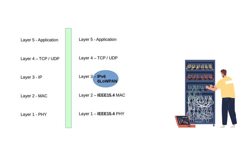
6LoWPAN is an adaption layer between the data link and network layer ( RFC 4944 ). It becomes part of the network layer. So, instead of using IPv6 natively on the MAC layer, they have a shim layer that adapts between the data and network layer. As a network layer protocol, it doesn’t provide any functionality above layer 3. As a result, it is often used in conjunction with Constrained Application protocols ( CoAP ) and MQTT ( machine-to-machine (M2M)/”Internet of Things ) protocols.
6LoWPAN Range
Diagram: 6LoWPAN

6LoWPAN Range: Header compression and fragmentation

IPv6 allows a maximum packet size of 1280 bytes. However, the maximum transfer size 802.15.4 is a 127-byte MTU, meaning a complete IPv6 packet does not fit in a 15.4 frame. By default, a 127-byte 15.4 frame only leaves 33 bytes for the payload. This small frame-size support is one of the reasons why deploying a full IP stack would be challenging. A couple of things must be done to make this work and compliant with IPv6 standards. To use IPv6, we need to adjust header overhead and adaptations for MTU size.

The first thing we must do is bring fragmentation back to IPv6. To allow such packets, we define a fragmentation scheme. The 11-bit fragmentation header allows for a 2048-byte packet size with fragmentation. However, many tables in the IPv6 header are static, and you might not need them. So, the version will always be 0, and so will the traffic class and flow label. 

Finally, for the Internet of Things networking, remember that the entire TCP/IP stack is not one size fits all and would certainly reach hardware limitations on small devices. It’s better to use UDP ( DTLS ) instead of TCP. Packet loss on the lossy network may invoke additional latencies while TCP carries out retransmissions. You can still use TCP, but it won’t be optimized, and the headers will not be compressed.

6LoWPAN technology offers a low-power and cost-effective solution for IoT deployments. By understanding the factors influencing its range, implementing range-extending techniques, and optimizing network parameters, organizations can ensure reliable connectivity and seamless communication within their IoT ecosystems. As the IoT landscape continues to evolve, 6LoWPAN will remain a vital connectivity option, enabling innovative applications and driving the growth of the IoT industry.

Summary: 6LoWPAN Range

In the vast Internet of Things (IoT) technologies, 6LoWPAN (IPv6 over Low-power Wireless Personal Area Network) stands out for its remarkable range of capabilities. This blog post delved into the fascinating world of the 6LoWPAN range, highlighting its benefits, limitations, and real-world applications.

Understanding 6LoWPAN Range

6LoWPAN, built on the IPv6 protocol, enables low-power devices to connect and communicate over wireless networks. One of its key features is its impressive range, which allows devices to transmit data over considerable distances without compromising power efficiency. Using mesh networking and efficient routing protocols, 6LoWPAN extends its reach beyond traditional wireless technologies.

Benefits of Extended Range

The extensive range of 6LoWPAN opens up many possibilities for various IoT applications. From smart agriculture to industrial automation, the ability to connect devices over long distances provides unprecedented flexibility and scalability. This extended range enables seamless connectivity even in challenging environments like large-scale industrial sites or expansive agricultural fields.

Limitations and Challenges

While 6LoWPAN offers impressive range capabilities, it is essential to acknowledge its limitations. Factors like physical obstacles, interference, and signal attenuation can affect the range experienced in real-world deployments. Additionally, power consumption may increase when devices need to transmit data over longer distances. Understanding these limitations is crucial for optimizing 6LoWPAN deployments and ensuring reliable connectivity.

Real-World Applications

The extensive range of 6LoWPAN has found applications in various industries. Intelligent cities enable efficient monitoring and control of infrastructure across vast urban areas. In healthcare, 6LoWPAN facilitates remote patient monitoring, connecting medical devices over extended distances. Additionally, environmental monitoring allows for comprehensive data collection across expansive regions.

Conclusion:

The remarkable range capabilities of 6LoWPAN make it a compelling choice for IoT deployments. Its ability to connect low-power devices over long distances opens up endless possibilities for industries and applications. However, it is crucial to consider the limitations and optimize deployments accordingly. As technology continues to evolve, we can expect further advancements in the 6LoWPAN range, unlocking even more opportunities for the future of IoT.

nominum

Nominum Security Report

I had the pleasure to contribute to Nominum’s Security Report. Kindly click on the link to register and download – Matt Conran with Nominum

“Nominum Data Science just released a new Data Science and Security report that investigates the largest threats affecting organizations and individuals, including ransomware, DDoS, mobile device malware, IoT-based attacks and more. Below is an excerpt:

October 21, 2016, was a day many security professionals will remember. Internet users around the world couldn’t access their favorite sites like Twitter, Paypal, The New York Times, Box, Netflix, and Spotify, to name a few. The culprit: a massive Distributed Denial of Service (DDoS) attack against a managed Domain Name System (DNS) provider not well-known outside technology circles. We were quickly reminded how critical the DNS is to the internet as well as its vulnerability. Many theorize that this attack was merely a Proof of Concept, with far bigger attacks to come”


Kubernetes PetSets

Kubernetes PetSets

Kubernetes PetSets

In the rapidly evolving landscape of container orchestration, Kubernetes has emerged as a powerful tool for managing and scaling applications. While it excels at handling stateless workloads, managing stateful applications has traditionally been more complex. However, with the introduction of Kubernetes Petsets, a new paradigm has emerged to simplify the management of stateful applications.

Stateful applications, unlike their stateless counterparts, require persistent storage and unique network identities. They maintain data and state across restarts, making them crucial for databases, queues, and other similar workloads. However, managing stateful applications in a distributed environment can be challenging, leading to potential data loss and inconsistencies.

Introducing Kubernetes Petsets: Kubernetes Petsets provide a solution for managing stateful applications within a Kubernetes cluster. Petsets ensure that each pod in the set has a unique identity, stable network hostname, and ordered deployment. This allows for predictable scaling, rolling updates, and seamless recovery in case of failures. With Petsets, you can now easily manage stateful applications in a declarative manner, leveraging the power of Kubernetes.

Petsets offer several key features that simplify the management of stateful applications. Firstly, they ensure ordered pod creation and scaling, guaranteeing that pods are created and deleted in a predictable sequence. This is crucial for maintaining data consistency and avoiding race conditions. Secondly, Petsets provide stable network identities, allowing other applications within the cluster to easily discover and communicate with the pods. Lastly, Petsets support rolling updates and automated recovery, minimizing downtime and ensuring high availability.

While Petsets bring simplicity to managing stateful applications, it's important to follow best practices for optimal usage. One key practice is to carefully plan and configure storage for your Petset pods, ensuring that you use appropriate volume types and storage classes. Additionally, monitoring and observability play a crucial role in identifying any issues with your Petsets and taking proactive actions.

Kubernetes Petsets have revolutionized the management of stateful applications within a Kubernetes cluster. With their unique features and benefits, Petsets enable developers to focus on building robust and scalable stateful applications, without the complexity of manual management. As Kubernetes continues to evolve, Petsets remain a valuable tool for simplifying the deployment and scaling of stateful workloads.

Highlights: Kubernetes PetSets

Stateful Applications with Kubernetes PetSets

a) PetSets, introduced in Kubernetes version 1.3, provides a higher-level abstraction for managing stateful applications. Unlike traditional Kubernetes deployments, which focus on stateless workloads, PetSets offer features like stable network identities, ordered deployment, and automated scaling while considering the application’s stateful nature.

b) One key challenge in scaling stateful applications is ensuring stable network identities. PetSets addresses this by providing stable hostnames and domain names for each replica of the stateful application. This allows clients to consistently connect to the same replica, even when scaling or restarting instances.

c) PetSets enable ordered deployment and scaling of stateful applications. This is crucial when dealing with applications that rely on specific ordering or coordination between instances. With PetSets, you can define a startup order for your replicas, ensuring that each replica is fully operational before the next one starts.

Benefits of PetSets

PetSets offer several advantages over traditional Kubernetes deployments:

1. Stable Network Identity: PetSets assigns each pod a stable hostname and DNS identity, enabling seamless communication between pods and external services. This stability is essential for applications relying on peer-to-peer communication or distributed databases.

2. Ordered Deployment: PetSets ensure the ordered deployment and scaling of pods. This is particularly useful for applications where the order of creation or scaling matters, such as databases or distributed systems.

3. Persistent Volumes: PetSets facilitate the association of persistent volumes with pods, ensuring data durability and allowing applications to retain their state even if the pods are rescheduled.

4. Rolling Updates: PetSets supports rolling updates, enabling you to update your stateful applications without downtime. This process ensures that each pod is gracefully terminated and replaced by a new one with the updated configuration, minimizing service interruptions.

Understanding Kubernetes PetSet

A – ) Kubernetes PetSet, also known as StatefulSet in more recent versions, is designed to manage stateful applications that require stable network identities and persistent storage. Unlike traditional Kubernetes Deployments, PetSet ensures that each pod in a set has a unique and stable hostname, allowing applications to maintain their identity and communicate effectively with other components in the cluster.

B – ) PetSet offers several key features that make it a valuable tool for managing stateful applications. One of its primary benefits is the ability to automatically provision and manage persistent volumes for each pod in the set. This ensures data durability and allows applications to seamlessly recover from pod failures without losing critical data. Additionally, PetSet provides ordered pod creation and termination, allowing for smooth scaling and rolling updates while preserving the application’s state.

C – ) Kubernetes PetSet finds application in various scenarios where stateful workloads are involved. One common use case is running databases, such as MySQL or PostgreSQL, in a distributed fashion. PetSet ensures that each replica of the database has a stable and unique identity, enabling seamless replication and failover. Other use cases include running distributed file systems, message queues, and other stateful applications that require stable network identities and persistent storage.

D – ) To effectively utilize Kubernetes PetSet, it’s essential to follow some best practices. Firstly, carefully design your application to ensure it can handle pod failures and rescheduling. Leveraging persistent volumes and configuring appropriate storage classes is crucial for data durability and availability. Additionally, monitoring the health and performance of your PetSet pods and implementing proper scaling strategies will help optimize the overall performance of your stateful application.

PetSets Use Cases: – 

PetSets are ideal for various stateful applications, including databases, distributed systems, and legacy applications that require stable network identities and persistent storage. Some everyday use cases for PetSets include:

1. Running a replicated database cluster, such as MySQL or PostgreSQL, where each pod corresponds to a separate database node.

2. Managing distributed messaging systems, like Apache Kafka or RabbitMQ, where each pod represents a separate broker or message queue.

3. Deploying legacy applications that rely on stable network identities and persistent storage, such as content management systems or enterprise resource planning software.

**Example: Detera and stateful applications**

In Kubernetes, persistent volumes are critical as customers migrate from stateless workloads to stateful applications. Pet Sets have significantly improved Kubernetes’ support for stateful applications like MySQL, Kafka, Cassandra, and Couchbase. It was possible to automate the scaling of the “Pets” (applications that need persistent placement and consistent handling) using sequencing provisioning and startup procedures.

The Role of FlexVolume:

Datera integrates seamlessly with Kubernetes using FlexVolume, an elastic block storage system for cloud deployments. Based on the first principles of containers, Datera decouples the provisioning of application resources from the underlying physical infrastructure. Clean contracts (i.e., not dependent on physical infrastructure), declarative formats, and declarative formats can eventually make stateful applications portable.

YAML Configurations:

With Datera, Kubernetes allows the underlying application infrastructure to be defined through YAML configurations, which are passed to the storage infrastructure. Datara AppTemplates can automate the scaling of stateful applications in a Kubernetes environment.

**The Role of Kubernetes**

Kubernetes Pets and PetSets are core components of Kubernetes operations. Firstly, Kubernetes is a container orchestration platform that runs and manages containers. It changes the focus of container deployment to an application level, not the machine. The shift of focus point enables an abstraction level and the removal of dependencies between the application and its physical deployment.

**The Role of Decoupling**

This act of decoupling services from the details of low-level physical deployment enables better service management. For anything to scale, you need to provide some abstraction. For container networking, we have seen this in the overlay world with underlay and abstraction enabling networks to support millions of tenants.  

**Kubernetes Networking 101**

Kubernetes Networking 101 allows the deployment of applications to a “sea of abstracted computes,” enabling a self-healing orchestrated infrastructure. While this scaling and deployment have been helpful for stateless services, they fall short in the stateful world with the base Kubernetes distribution. Most of this has been solved today with Red Hat products, including OpenShift networking, which has several new network and security constructs that aid with stateful application support.

For pre-information, you may find the following useful

  1. SASE Model
  2. Chaos Engineering Kubernetes
  3. Kubernetes Security Best Practices
  4. OpenShift SDN 
  5. Hands On Kubernetes
  6. Kubernetes Namespace
  7. Container Scheduler


Kubernetes PetSets

Discussing StatefulSets

Kubernetes started providing a resource to manage stateful workloads with the alpha release of PetSets in the 1.3 release. This capability has matured and is now known as StatefulSets. A StatefulSet has some similarities to a ReplicaSet in that it is responsible for managing the lifecycle of a set of Pods, but how it goes about this management has some noteworthy differences. PetSet might seem like an odd name for a Kubernetes resource, and it has since been replaced.

Still, it provides fascinating insights into the Kubernetes community’s thought process for supporting stateful workloads. The fundamental idea is that there are two ways of handling servers: to treat them as pets that require care, feeding, and nurturing or to treat them as cattle to which you don’t develop an attachment or provide much individual attention. If you’re logging into a server regularly to perform maintenance activities, you treat it as a pet.

**Contrasting Application Models**

As applications serve a growing user base around the globe, single cluster and data center solutions are no longer satisfying. Clustered applications and federations enable workloads to spread across multiple locations and container clusters for improved efficiency and scale. You will find contrasting deployment models when you examine the application types and scaling modes (for example, scale-up and scale-out clustering ).

There are substantial differences between deploying and running single applications to applications that operate within a cluster. Different application architectures require different deployment solutions and network identities. For example, a database node requires persistent volumes, or a node within a cluster uses specific elections where identity is essential. 

**Kubernetes Pets **

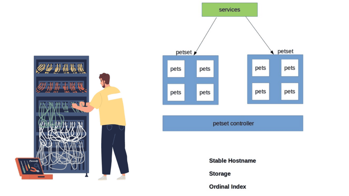
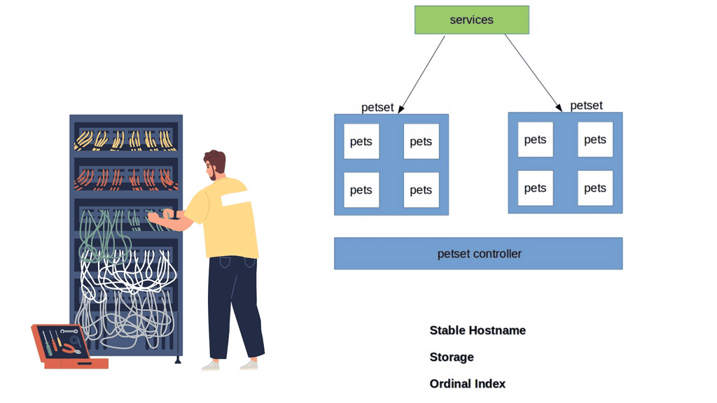
Kubernetes has recently ramped up by introducing a new Kubernetes object called PetSets. PetSets is geared towards improving stateful support and is currently an alpha resource in Kubernetes release 1.3. It holds a group of Kubernetes Pets, aka stateful applications that require stable hostnames, persistent disks, a structured lifecycle process, and group identity. 

PetSets are used for non-homogenous instances where each POD has a stable distinguishable identity. A different identity is viewed in terms of stable network and storage. 

A ) Stable network identities such as DNS and hostname.

B ) Stable storage identity.

Before PetSets, stateful applications were supported but exceedingly challenging to deploy and manage, especially regarding distributed stateful clusters. In addition, PODs had random names that could not be relied upon. With the introduction of PetSets controllers and Kubernetes Pets, Kubernetes has sharpened its support for stateful and distributed stateful applications.

Kubernetes PetSets
Diagram: Kubernetes PetSets

Challenges: PODs and their shortcomings 

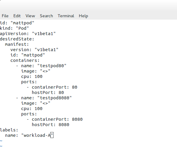
Kubernetes enables the specification of applications as a POD file, expressed in YAML or JSON format. The file specifies what containers are to be in a POD. PODs are the smallest deployment unit in Kubernetes and present several challenges for some stateful services. They do not offer a singleton pattern and are temporary by design.

Their constructs are mortal as they are born and die but never resurrected. When a POD dies, it’s permanently gone and replaced with a new instance and fresh identity. This operation model may suit some applications but falls short for others who want to retain identity and storage across restart / reschedule. 

Challenges: Replication Controllers and their shortcomings

If you want a POD to resurrect, you need a Replication Controller ( RC ). The RC enables a singleton pattern to set replication patterns to a specific number of PODs.

The introduction of the RC is undoubtedly a step in the right direction, as it ensures the correct number of replicas are always running at any given time. The RC works alongside services before the RC, using labels to map inbound requests to certain PODs.

Services provide a level of abstraction so that the application endpoint never changes. RC is suitable for application deployments requiring weak uncoupled identities, and when naming individual PODs doesn’t matter to the application architecture.

However, they lack certain functionalities that the new PetSet controller provides. So you could say that a PetSet controller is an enhanced RC controller in shiny new clothes.

A key point: “Pets and Cattle.” 

The best way to understand Kubernetes Pets and PetSets is to perceive the cloud infrastructure with the “Pets and Cattle” metaphor. A“Pet” is a special snowflake you have emotional ties towards and requires special handling, for example, when it’s sick, unlike “Cattle,” which is viewed as an easily replaceable commodity.

Cattle are similar enough to each other that you can treat them all as equals. Therefore, the application does not suffer much if a cattle dies or needs replacement.

  • Cattle refers to stateless applications, and Pets refer to stateful, “build once, run anywhere” applications.

Discussing Stateless applications

A stateless application takes in a request and responds, but nothing is left behind to fulfill subsequent connections. The stateless pattern derives from another independent system’s ability to satisfy subsequent requests/responses. Stateful applications store data for further use. These types of applications can be inspected with a stateful inspection firewall.

Note: PetSet Objects

Stateful applications are grouped into what’s known as a PetSet object. The PetSet controller has a family-orientated approach, as opposed to the traditional RC, which is mainly concerned with the number of replicas. PODs are stateless disposable units that can be removed and interchanged without affecting the application. The Pets, conversely, are groups of stateful PODs requiring stronger different identities.

Note: PetSet Identities 

Within a PetSet, Pets ( stateful applications ) have a unique, distinguishable identity. The identities stick and do not change when restarting/rescheduling. They have an explicit purpose/role in life that is known throughout the family—a definitive startup carried out in a structured order that fits within its responsibility in the application’s framework.

Initially, the cattle approach forced us to view cloud components as anonymous resources. However, this approach does not fit all application requirements. Stateful applications require us to rethink the new pet-style approach. 

Workloads and Application Types Suitable for Pets:

Stateful application within a PetSet object requires unique identities such as : 

  1. Storage
  2. Ordinal index
  3. Stable Hostname

The PetSet object supports clustered applications that require stricter membership and identity requirements, such as : 

  1. Discovery of peers for quorum
  2. Startup and Teardown

Workloads that benefit from PetSets include, for example :

  1. NoSQL databases – clustered software like Cassandra, Zookeeper, etcd, requiring regular membership.
  2. Relationshional Databases – MySQL or PostgreSQL requiring persistent volumes. 

Application Roles & Responsibilities 

Applications have different roles and responsibilities, requiring different deployment models. For example, a Cassandra cluster has strict membership and identity requirements; specific nodes are designated seed nodes used during startup to discover the cluster.

They come first and act as the contact points for all other nodes to get information about the cluster. All nodes require one seed node, and all nodes within a cluster must have the same seed node. No node can join the cluster without a seed node, meaning their role is vital for the application framework.

Note: Zookeeper – Identification of Peers

Zookeeper or etcd requires the identification of peers and instances clients should contact. Other databases have a master/slave model where the master has unidirectional control over the slave. The “primary” server has a different role and identity requirements than the “slave.” Properly running these types of services requires more complex features in Kubernetes.

Closing Points on Kubernetes PetSets

PetSets, now more commonly known as StatefulSets, are a Kubernetes resource designed to manage stateful applications. Unlike the standard ReplicaSets that manage stateless applications by treating all replicas as identical, PetSets offer a more sophisticated way to manage pods. Each pod in a PetSet has a guaranteed unique identity, stable networking, and persistent storage, making them ideal for databases, caches, and other applications that require stable identities.

One of the standout features of PetSets is their ability to maintain a stable identity for each pod, which is crucial for stateful applications. This includes:

– **Persistent Storage:** Each pod in a PetSet can have its own persistent volume, ensuring that data is retained across restarts.

– **Ordered Deployment and Scaling:** PetSets ensure that pods are deployed or scaled up in a specific order, which is essential for applications with interdependencies.

– **Stable Network Identity:** Each pod retains its network identity, which is important for applications that rely on consistent access to resources.

Deploying a stateful application using PetSets involves defining a StatefulSet resource in your Kubernetes cluster. This resource specifies the desired number of replicas, the template for the pods, and any associated persistent volumes. By following best practices in your configurations, you can ensure that your stateful applications benefit from the stability and reliability that PetSets offer.

PetSets are particularly beneficial for applications like databases (e.g., MySQL, Cassandra), distributed file systems (e.g., HDFS), and other systems that require stable identities and persistent storage. By utilizing PetSets, organizations can ensure high availability and resilience for their critical stateful applications, even in dynamic environments.

Summary: Kubernetes PetSets

Kubernetes has revolutionized container orchestration, enabling developers to manage and scale their applications efficiently. Among its many features, Kubernetes PetSets offers a powerful way to manage stateful applications. In this blog post, we delved into the intricacies of Kubernetes PetSets, exploring their functionality, use cases, and best practices.

Understanding PetSets

PetSets, introduced in Kubernetes 1.3, are a higher-level abstraction built on top of StatefulSets. They provide a way to deploy and manage stateful applications in a Kubernetes cluster. PetSets allow you to assign stable hostnames and persistent storage to each pod replica, making them ideal for applications requiring unique identities and data persistence.

Use Cases for PetSets

PetSets are particularly beneficial for applications like databases, message queues, and distributed file systems, which require stable network identities and persistent storage. Using PetSets, you can ensure that each replica of your stateful application has its unique hostname and storage, enabling seamless scaling and failover.

How to Create a PetSet

Creating a PetSet involves defining a template for the pods that make up the replica set. This template specifies attributes such as the container image, resource requirements, and volume claims. Additionally, you can define the ordering and readiness requirements for the pods within the PetSet. We’ll walk you through the step-by-step process of creating a PetSet and highlight important considerations.

Scaling and Updating PetSets

One of PetSets’ key advantages is its ability to scale and update stateful applications seamlessly. We’ll explore the different scaling strategies, including vertical and horizontal scaling, and discuss how to handle rolling updates without compromising your PetSet’s availability and data integrity.

Monitoring and Troubleshooting PetSets

Monitoring and troubleshooting are crucial for managing any application in a production environment. We’ll cover the best practices for monitoring the health and performance of your PetSets and standard troubleshooting techniques to help you identify and resolve issues quickly.

Conclusion:

Kubernetes PetSets provides a powerful solution for managing stateful applications in a Kubernetes cluster. By combining stable hostnames and persistent storage with the benefits of container orchestration, PetSets offers a reliable and scalable approach to deploying and scaling your stateful workloads. Understanding the nuances of PetSets and following best practices will empower you to harness the full potential of Kubernetes for your applications.

Event Stream Processing

Event Stream Processing

Event Stream Processing

Event Stream Processing (ESP) has emerged as a groundbreaking technology, transforming the landscape of real-time data analytics. In this blog post, we will delve into the world of ESP, exploring its capabilities, benefits, and potential applications. Join us on this exciting journey as we uncover the untapped potential of event stream processing.

ESP is a cutting-edge technology that allows for the continuous analysis of high-velocity data streams in real-time. Unlike traditional batch processing, ESP enables organizations to harness the power of data as it flows, making instant insights and actions possible. By processing data in motion, ESP empowers businesses to react swiftly to critical events, leading to enhanced decision-making and improved operational efficiency.

Real-Time Data Processing: ESP enables organizations to process and analyze data as it arrives, providing real-time insights and enabling immediate actions. This capability is invaluable in domains such as fraud detection, IoT analytics, and financial market monitoring.

Scalability and Performance: ESP systems are designed to handle massive volumes of data with low latency. The ability to scale horizontally allows businesses to process data from diverse sources and handle peak loads efficiently.

Complex Event Processing: ESP platforms provide powerful tools for detecting patterns, correlations, and complex events across multiple data streams. This enables businesses to uncover hidden insights, identify anomalies, and trigger automated actions based on predefined rules.

Financial Services: ESP is revolutionizing the financial industry by enabling real-time fraud detection, algorithmic trading, risk management, and personalized customer experiences.

Internet of Things (IoT): ESP plays a crucial role in IoT analytics by processing massive streams of sensor data in real-time, allowing for predictive maintenance, anomaly detection, and smart city applications.

Supply Chain Optimization: ESP can help organizations optimize their supply chain operations by monitoring and analyzing real-time data from various sources, including inventory levels, logistics, and demand forecasting.

Event stream processing has opened up new frontiers in real-time data analytics. Its ability to process data in motion, coupled with features like scalability, complex event processing, and real-time insights, make it a game-changer for businesses across industries. By embracing event stream processing, organizations can unlock the true value of their data, gain a competitive edge, and drive innovation in the digital age.

Highlights: Event Stream Processing

Real-time Data Streams

Event Stream Processing, also known as ESP, is a computing paradigm that allows for analyzing and processing real-time data streams. Unlike traditional batch processing, where data is processed in chunks or batches, event stream processing deals with data as it arrives, enabling organizations to respond to events in real time. ESP empowers businesses to make timely decisions, detect patterns, and identify anomalies by continuously analyzing and acting upon incoming data.

Event Stream Processing is a method of analyzing and deriving insights from continuous streams of data in real-time. Unlike traditional batch processing, ESP enables organizations to process and respond to data as it arrives, enabling instant decision-making and proactive actions. By leveraging complex event processing algorithms, ESP empowers businesses to unlock actionable insights from high-velocity, high-volume data streams.

ESP Key Points: 

  • Real-time Insights: One critical advantage of event stream processing is gaining real-time insights. By processing data as it flows in, organizations can detect and respond to essential events immediately, enabling them to seize opportunities and mitigate risks promptly.
  • Scalability and Flexibility: Event stream processing systems are designed to handle massive amounts of real-time data. These systems can scale horizontally, allowing businesses to process and analyze data from multiple sources concurrently. Additionally, event stream processing offers flexibility regarding data sources, supporting various input streams such as IoT devices, social media feeds, and transactional data.
  • Fraud Detection: Event stream processing plays a crucial role in fraud detection by enabling organizations to monitor and analyze real-time transactions. By processing transactional data as it occurs, businesses can detect fraudulent activities and take immediate action to prevent financial losses.
  • Predictive Maintenance: With event stream processing, organizations can monitor and analyze sensor data from machinery and equipment in real time. By detecting patterns and anomalies, businesses can identify potential faults or failures before they occur, allowing for proactive maintenance and minimizing downtime.
  • Supply Chain Optimization: Event stream processing helps optimize supply chain operations by providing real-time visibility into inventory levels, demand patterns, and logistics data. By continuously analyzing these data streams, organizations can make data-driven decisions to improve efficiency, reduce costs, and enhance customer satisfaction.

Example: Apache Flink and Stateful Stream Processing

a) Apache Flink provides an intuitive and expressive API for implementing stateful stream processing applications. These applications can be run fault-tolerantly on a large scale. The Apache Software Foundation incubated Flink in April 2014, and it became a top-level project in January 2015. Since its inception, Flink’s community has been very active.

b) Thanks to the contributions of more than five hundred people, Flink has evolved into one of the most sophisticated open-source stream processing engines. Flink powers large-scale, business-critical applications across various industries and regions.

c) In addition to offering superior solutions for many established use cases, such as data analytics, ETL, and transactional applications, stream processing technology facilitates new applications, software architectures, and business opportunities for companies of all sizes.

d) Data and data processing have been ubiquitous in businesses for decades. Companies are designing and building infrastructures to manage data, which has increased over the years. Transactional and analytical data processing are standard in most businesses.

**Massive Amounts of Data**

It’s a common theme that the Internet of Things is all about data. IoT represents a massive increase in data rates from multiple sources that need to be processed and analyzed from various Internet of Things access technologies.

In addition, various heterogeneous sensors exhibit a continuous stream of information back and forth, requiring real-time processing and intelligent data visualization with event stream processing (ESP) and IoT stream processing.

This data flow and volume shift may easily represent thousands to millions of events per second. It is the most significant kind of “big data” and will exhibit considerably more data than we have seen on the Internet of humans. Processing large amounts of data from multiple sources in real time is crucial for most IoT solutions, making reliability in distributed systems a pivotal factor to consider in the design process.

**Data Transmission**

Data transmitted between things instructs how to act and react to certain conditions and thresholds. Analysis of this data turns data streams into meaningful events, offering unique situational awareness and insight into the thing transmitting the data. This analysis allows engineers and data science specialists to track formerly immeasurable processes. 

Before you proceed, you may find the following helpful:

  1. Docker Container Security
  2. Network Functions
  3. IP Forwarding
  4. OpenContrail
  5. Internet of Things Theory
  6. 6LoWPAN Range

Event Stream Processing

Stream processing technology is increasingly prevalent because it provides superior solutions for many established use cases, such as data analytics, ETL, and transactional applications. It also enables novel applications, software architectures, and business opportunities. With traditional data infrastructures, data and data processing have been omnipresent in businesses for many decades.

Over the years, data collection and usage have grown consistently, and companies have designed and built infrastructures to manage that data. However, the traditional architecture that most businesses implement distinguishes two types of data processing: transactional processing and analytical processing.

Analytics and Data Handling are Changing.

All this type of new device information enables valuable insights into what is happening on our planet, offering the ability to make accurate and quick decisions. However, analytics and data handling are challenging. Everything is now distributed to the edge, and new ways of handling data are emerging.

To combat this, IoT uses emerging technologies such as stream data processing with in-stream analytics, predictive analytics, and machine learning techniques. In addition, IoT devices generate vast amounts of data, putting pressure on the internet infrastructure. This is where the role of cloud computing comes in useful. Cloud computing assists in storing, processing, and transferring data in the cloud instead of connected devices.

Organizations can utilize various technologies and tools to implement event stream processing (ESP). Some popular ESP frameworks include Apache Kafka, Apache Flink, and Apache Storm. These frameworks provide the infrastructure and processing capabilities to handle high-speed data streams and perform real-time analytics. 

IoT Stream Processing: Distributed to the Edge

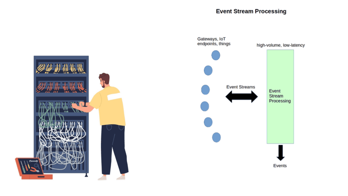
1: IoT represents a distributed architecture. Analytics are distributed from the IoT platform, either cloud or on-premise, to network edges, making analytics more complicated. A lot of the filtering and analysis is carried out on the gateways and the actual things themselves. These types of edge devices process sensor event data locally.

2: Some can execute immediate local responses without contacting the gateway or remote IoT platform. A device with sufficient memory and processing power can run a lightweight version of an Event Stream Processing ( ESP ) platform.

3: For example, Raspberry PI supports complex-event processing ( CEP ). Gateways ingest event streams from sensors and usually carry out more sophisticated steam processing than the actual thing. Some can send an immediate response via a control signal to actuators, causing a state change.

Technicality is only one part of the puzzle; data ownership and governance are the other. 

Time Series Data – Data in Motion

In specific IoT solutions, such as traffic light monitoring in intelligent cities, reaction time must be immediate without delay. This requires a different type of big data solution that processes data while it’s in motion. In some IoT solutions, there is too much data to store, so the analysis of data streams must be done on the fly while being transferred.

It’s not just about capturing and storing as much data as possible anymore. The essence of IoT is the ability to use the data while it is still in motion. Applying analytical models to data streams before they are forwarded enables accurate pattern and anomaly detection while they are occurring. This analysis offers immediate insight into events, enabling quicker reaction times and business decisions. 

Traditional analytical models are applied to stored data, offering analytics for historical events only. IoT requires the examination of patterns before data is stored, not after. The traditional store and process model does not have the characteristics to meet the real-time analysis of IoT data streams.

In response to new data handling requirements, new analytical architectures are emerging. The volume and handling of IoT traffic require a new type of platform known as Event Stream Processing ( ESP ) and Distributed Computing Platforms ( DCSP )

Event Stream Processing
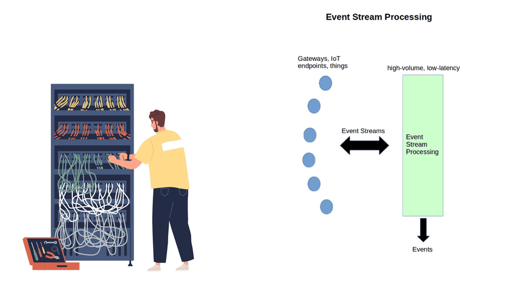
Diagram: Event Stream Processing.

Event Stream Processing ( ESP ) 

ESP is an in-memory, real-time process technique that enables the analysis of continuously flowing events in data streams. Assessing events in motion is known as “event streams.” This reveals what is happening now and can be used with historical data to predict future events accurately. Predictive models are embedded into the data streams to predict future events.

This type of processing represents a shift in data processing. Data is no longer stored and processed; it is analyzed while still being transferred, and models are applied.

ESP & Predictive Analytics Models

ESP applies sophisticated predictive analytics models to data streams and then takes action based on those scores or business rules. It is becoming popular in IoT solutions for predictive asset maintenance and real-time fault detection.

For example, you can create models that signal a future unplanned condition. This can then be applied to ESP, quickly detecting upcoming failures and interruptions. ESP is also commonly used in network optimization of the power grid and traffic control systems.

ESP – All Data in RAM

ESP is in-memory, meaning all data is loaded into RAM. It does not use hard drives or substitutes, resulting in fast processing, enhanced scale, and analytics. In-memory can analyze terabytes of data in just a few seconds and can ingest from millions of sources in milliseconds. All the processing happens at the system’s edge before data is passed to storage.

How you define real-time depends on the context. Your time horizon will depict whether you need the full power of ESP. Events with ESP should happen close together in time and frequency. However, if your time horizon is over a relatively long period and events are not close together, your requirements might be fulfilled with Batch processing. 

**Batch vs Real-Time Processing**

With Batch processing, files are gathered over time and sent together as a batch. It is commonly used when fast response times are not critical and for non-real-time processing. Batch jobs can be stored for an extended period and then executed; for example, an end-of-day report is suited for batch processing as it does not need to be done in real-time.

They can scale, but the batch orientation limits real-time decision-making and IoT stream requirements. Real-time processing involves a continual input, process, and output of data. Data is processed in a relatively short period. When your solution requires immediate action, real-time is the one for you. Examples of batch and real-time solutions include Hadoop for batch and Apache Spark, focusing on real-time computation.

**Hadoop vs. Apache Spark** 

Hadoop is a distributed data infrastructure that distributes data collections across nodes in a cluster. It includes a storage component called Hadoop Distributed File System ( HDFS ) and a processing component called MapReduce. However, with the new requirements for IoT, MapReduce is not the answer for everything.

MapReduce is fine if your data operation requirements are static and you can wait for batch processing. But if your solution requires analytics from sensor streaming data, then you are better off using Apache Spark. Spark was created in response to MapReduce’s limitations.

Apache Spark does not have a file system and may be integrated with HDFS or a cloud-based data platform such as Amazon S3 or OpenStack SwiftIt is much faster than MapReduce and operates in memory and real-time. In addition, it has machine learning libraries to gain insights from the data and identify patterns. Machine learning can be as simple as a Python event and anomaly detection script.

Closing Points on Event Stream Processing 

Event Stream Processing is a computing paradigm focused on the real-time analysis of data streams. Unlike traditional batch processing, which involves collecting data and analyzing it periodically, ESP allows for immediate insights as data flows in. This capability is crucial for applications that demand instantaneous action, such as fraud detection in financial transactions or monitoring network security.

The architecture of an Event Stream Processing system typically comprises several key components:

1. **Event Sources**: These are the origins of the data streams, which could be sensors, user actions, or any system generating continuous data.

2. **Stream Processor**: The core of ESP, where the actual computation and analysis occur. It processes the data in real-time, applying various transformations and detecting patterns.

3. **Data Sink**: This is where the processed data is delivered, often to databases, dashboards, or triggering subsequent actions.

4. **Messaging System**: A crucial part of ESP, it ensures that data flows seamlessly from the source to the processor and finally to the sink.

The versatility of ESP makes it applicable across numerous industries:

– **Finance**: ESP is used in algorithmic trading, risk management, and fraud detection, providing real-time insights that drive decisions.

– **Healthcare**: In monitoring patient vitals and managing hospital operations, ESP enables timely interventions and improved resource allocation.

– **Telecommunications**: ESP helps in network monitoring, ensuring optimal performance and quick resolution of issues.

– **E-commerce**: Companies use ESP to personalize user experiences by analyzing browsing and purchasing behaviors in real-time.

Implementing ESP can be challenging due to the need for reliable and scalable infrastructure. Key considerations include:

– **Latency**: Minimizing the delay between data generation and analysis is crucial for effectiveness.

– **Scalability**: As data volumes increase, the system must efficiently handle larger streams without performance degradation.

– **Data Quality**: Ensuring data accuracy and consistency is essential for meaningful analysis.

Summary: Event Stream Processing

In today’s fast-paced digital world, the ability to process and analyze data in real time has become crucial for businesses across various industries. Event stream processing is one technology that has emerged as a game-changer in this realm. In this blog post, we will explore the concept of event stream processing, its benefits, and its applications in different domains.

Understanding Event Stream Processing

Event stream processing is a method of analyzing and acting upon data generated in real time. Unlike traditional batch processing, which deals with static datasets, event stream processing focuses on continuous data streams. It involves capturing, filtering, aggregating, and analyzing events as they occur, enabling businesses to gain immediate insights and take proactive actions.

Benefits of Event Stream Processing

Real-Time Insights: Event stream processing processes data in real time, allowing businesses to derive insights and make decisions instantly. This empowers them to respond swiftly to changing market conditions, customer demands, and emerging trends.

Enhanced Operational Efficiency: Event stream processing enables businesses to automate complex workflows, detect anomalies, and trigger real-time alerts. This leads to improved operational efficiency, reduced downtime, and optimized resource utilization.

Seamless Integration: Event stream processing platforms seamlessly integrate existing IT systems and data sources. This ensures that businesses can leverage their existing infrastructure and tools, making implementing and scaling event-driven architectures easier.

Applications of Event Stream Processing

Financial Services: Event stream processing is widely used in the financial sector for real-time fraud detection, algorithmic trading, and risk management. By analyzing vast amounts of transactional data in real time, financial institutions can identify suspicious activities, make informed trading decisions, and manage risks.

Internet of Things (IoT): With the proliferation of IoT devices, event stream processing has become crucial for managing and extracting value from the massive amounts of data generated by these devices. It enables real-time monitoring, predictive maintenance, and anomaly detection in IoT networks.

Retail and E-commerce: Event stream processing lets retailers personalize customer experiences, optimize inventory management, and detect fraudulent transactions in real time. By analyzing customer behavior data in real time, retailers can deliver targeted promotions, ensure product availability, and prevent fraudulent activities.

Conclusion: Event stream processing is revolutionizing how businesses harness real-time data’s power. Providing instant insights, enhanced operational efficiency, and seamless integration empowers organizations to stay agile, make data-driven decisions, and gain a competitive edge in today’s dynamic business landscape.

Internet of Things Theory

Internet of Things Theory

The Internet of Things (IoT) is a concept that has rapidly gained momentum in recent years, transforming the way we live and interact with technology. With the proliferation of smart devices, interconnected sensors, and advanced data analytics, IoT is revolutionizing various industries and reshaping our daily lives. In this blog post, we will explore the fundamental aspects of the Internet of Things and its potential impact on our future.

The Internet of Things refers to the interconnectivity of physical devices, vehicles, appliances, and other objects embedded with sensors, software, and network connectivity. These devices are capable of collecting and exchanging data, enabling them to communicate and interact with each other without human intervention. IoT is transforming how we perceive and utilize technology, from smart homes and cities to industrial applications.

Sensors and Actuators: At the heart of the Internet of Things lies a network of sensors and actuators. Sensors collect data from the physical world, ranging from temperature and humidity to motion and light. These devices are equipped with the ability to detect and measure specific parameters, providing valuable real-time information.

Actuators, on the other hand, enable physical actions based on the data received from sensors. They can control various mechanisms, such as opening and closing doors, turning on and off lights, or regulating the temperature in a room.

Communication Protocols: For the IoT to function seamlessly, effective communication protocols are essential. These protocols enable devices to transmit data between each other and to the cloud. Some popular communication protocols in the IoT realm include Wi-Fi, Bluetooth, Zigbee, and LoRaWAN. Each protocol possesses unique characteristics that make it suitable for specific use cases. For instance, Wi-Fi is ideal for high-speed data transfer, while LoRaWAN offers long-range connectivity with low power consumption.

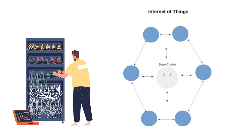
Cloud Computing and Data Analytics: The massive amount of data generated by IoT devices requires robust storage and processing capabilities. Cloud computing plays a pivotal role in providing scalable infrastructure to handle this data influx. By leveraging cloud services, IoT devices can securely store and access data, as well as utilize powerful computational resources for advanced analytics. Data analytics, in turn, enables organizations to uncover valuable insights, optimize operations, and make data-driven decisions.

Edge Computing: While cloud computing offers significant advantages, some IoT applications demand real-time responsiveness, reduced latency, and enhanced privacy. This is where edge computing comes into play. Edge devices, such as gateways and edge servers, bring computational power closer to the data source, enabling faster processing and decision-making at the edge of the network. Edge computing minimizes the need for constant data transmission to the cloud, resulting in improved efficiency and reduced bandwidth requirements.

Highlights: Internet of Things Theory

IoT Theory

IoT: The Fundamentals:

The IoT theory is built on the foundation of connectivity and intercommunication. It involves the integration of sensors, software, and networks to enable data exchange between devices. This section will delve into the core components of the IoT, including sensors, actuators, connectivity protocols, and cloud platforms that form the backbone of this interconnected ecosystem.

IoT has already made a significant impact on various aspects of our daily lives. In homes, smart devices like voice-activated assistants, security cameras, and lighting systems enhance convenience and security. In the healthcare sector, IoT enables remote patient monitoring, improving healthcare delivery and patient outcomes. Meanwhile, in industries such as agriculture, IoT is revolutionizing farming practices through precision agriculture, where sensors and analytics help optimize crop yields and resource management.

The Internet Transformation:

The Internet is transforming, and this post discusses the Internet of Things Theory and highlights Internet of Things access technologies. Initially, we started with the Web and digitized content. The market then moved to track and control the digitized world with, for example, General Packet Radio Service ( GPRS ). 

Machine-to-machine ( M2M ) connectivity introduces a different connectivity model and application use case. Now, we embark on Machine Learning, where machines can make decisions with supervised or unsupervised controls. This transformation requires new architecture and technologies to support IoT connectivity, including event stream processing and the 6LoWPAN range.

Note: IoT Theory Key Points:

– The IoT theory revolves around the concept of connecting everyday objects to the internet, enabling them to send and receive data. This section will explain the fundamental principles behind IoT, including sensors, connectivity, and data analysis.

– IoT has permeated various aspects of our daily lives, making activities more convenient and efficient. From smart homes that automate tasks to wearable devices that track health and fitness, this section will explore the numerous applications of IoT in our routines.

– Industries across the board have embraced IoT to streamline operations, enhance productivity, and reduce costs. We will take a closer look at how IoT is transforming manufacturing, transportation, healthcare, and agriculture, among other sectors.

– With the immense potential of IoT come significant impacts and challenges. This section will discuss the positive effects of IoT on sustainability, data analysis, and urban planning, as well as the concerns surrounding privacy, security, and data breaches.

**Distributed Edge Intelligence**

Traditional networks start with a group of network devices and a box-by-box mentality. The perimeter was more or less static. The move to Software-Defined Networking ( SDN ) implements a central controller, pushing networking into the software with the virtual overlay network. As we introduce the Internet of Things theory, the IoT world steadily progresses, and we require an application-centric model with distributed intelligence and time series data.

The Internet of Things theory connects everyday objects to the Internet, allowing them to communicate and share data. This section will provide a comprehensive overview of IoT’s fundamental concepts and components, including sensors, actuators, connectivity, and data analysis.

**Real-world Applications**

IoT has permeated various industries, from smart homes to industrial automation, bringing significant advancements. There are a showcase a range of practical applications, such as smart cities, wearable devices, healthcare systems, and transportation networks. By exploring these examples, readers will understand how IoT reshapes our lives.

**IoT Challenges and Concerns**

While the potential of IoT is immense, some challenges and concerns need to be addressed. This section will delve into data privacy, security vulnerabilities, ethical considerations, and the impact on the workforce. By understanding these challenges, we can work towards creating a safer and more sustainable IoT ecosystem.

The evolution of IoT theory is an ongoing process. In this section, we will explore the future implications of IoT, including the integration of artificial intelligence, machine learning, and blockchain technologies. Additionally, we will discuss the potential benefits and risks that lie ahead as the IoT landscape continues to expand.

Example Product: Cisco IoT Operations Dashboard

**What is the Cisco IoT Operations Dashboard?**

The Cisco IoT Operations Dashboard is a cloud-based platform designed to simplify the management and monitoring of IoT devices. With its user-friendly interface and robust features, this dashboard allows businesses to seamlessly integrate, manage, and secure their IoT deployments. Whether you’re overseeing a small network of sensors or a vast array of connected devices, the Cisco IoT Operations Dashboard offers a scalable solution that grows with your needs.

**Key Features and Benefits**

1. **Comprehensive Device Management**

The dashboard provides a centralized view of all connected devices, enabling administrators to monitor device status, performance, and connectivity. This holistic approach ensures that any issues can be quickly identified and resolved, minimizing downtime and enhancing productivity.

2. **Enhanced Security**

Security is paramount in any IoT deployment. The Cisco IoT Operations Dashboard incorporates advanced security features, including end-to-end encryption, secure boot, and firmware updates. These measures protect your network from potential threats and ensure the integrity of your data.

3. **Scalability and Flexibility**

As your IoT network expands, the Cisco IoT Operations Dashboard scales effortlessly to accommodate new devices and applications. Its flexible architecture supports a wide range of protocols and standards, making it compatible with diverse IoT ecosystems.

**Real-World Applications**

The versatility of the Cisco IoT Operations Dashboard makes it suitable for various industries. In manufacturing, for instance, it can monitor machinery health and predict maintenance needs, reducing downtime and operational costs. In agriculture, the dashboard can track soil moisture levels and weather conditions, optimizing irrigation and improving crop yields. The potential applications are vast, underscoring the dashboard’s value across different sectors.

**Getting Started with Cisco IoT Operations Dashboard**

Implementing the Cisco IoT Operations Dashboard is straightforward. Businesses can begin by identifying their IoT needs and selecting the appropriate devices and sensors. Once the hardware is in place, the dashboard provides guided setup instructions to connect and configure devices. With its intuitive interface, users can quickly familiarize themselves with the platform and start leveraging its features to enhance their operations.

Related: Before you proceed, you may find the following helpful.

  1. OpenShift Networking
  2. OpenStack Architecture

Internet of Things Theory

Internet of Things Theory and Use Cases

Applications of IoT:

The applications of IoT are vast and encompass various sectors, including healthcare, agriculture, transportation, manufacturing, and more. IoT is revolutionizing patient care in healthcare by enabling remote monitoring, wearable devices, and real-time health data analysis.

The agricultural industry benefits from IoT by utilizing sensors to monitor soil conditions and weather patterns and optimize irrigation systems. IoT enables intelligent traffic management, connected vehicles, and advanced navigation systems in transportation, enhancing efficiency and safety.

**Benefits and Challenges**

The Internet of Things offers numerous benefits, such as increased efficiency, improved productivity, enhanced safety, and cost savings. Smart homes, for instance, enable homeowners to control and automate various aspects of their living spaces, resulting in energy savings and convenience. IoT allows predictive maintenance, optimizes operations, and reduces downtime in the industrial sector.

However, with the vast amount of data generated by IoT devices, privacy and security concerns arise. Safeguarding sensitive information and protecting against cyber threats are critical challenges that must be addressed to ensure IoT’s widespread adoption and success.

**Enhanced Efficiency and Productivity**

With IoT, massive automation and real-time data collection have become possible. This translates into increased efficiency and productivity across industries. From smart factories optimizing production processes to automated inventory management systems, IoT streamlines operations and minimizes human intervention.

**Improved Quality of Life**

IoT has the potential to enhance our daily lives significantly. Smart homes with IoT devices allow seamless control of appliances, lighting, and security systems. Imagine waking up to a house that adjusts the temperature to your preference, brews your morning coffee, and even suggests the most efficient route to work based on real-time traffic data.

Leveraging IoT can significantly enhance safety and security measures. Smart surveillance systems can detect and react to potential threats in real-time. IoT-enabled wearable devices can monitor vital signs and send alerts during emergencies, ensuring timely medical assistance.

**Environmental Sustainability**

IoT plays a crucial role in promoting environmental sustainability. Smart grids enable efficient energy management and reduce wastage. IoT devices can monitor ecological parameters like air quality and water levels, facilitating proactive measures to protect our planet.

**The Future of IoT**

The Internet of Things has only scratched the surface of its potential. As technology advances, we can expect IoT to become more sophisticated and integrated into our daily lives.

The emergence of 5G networks will enable faster and more reliable connectivity, unlocking new possibilities for IoT applications. From intelligent cities that optimize energy consumption to personalized healthcare solutions, the future of IoT holds immense promise.

Example Product: Cisco Edge Device Manager

### What is Cisco Edge Device Manager?

Cisco Edge Device Manager is a cloud-based platform that provides centralized management for edge devices. It allows network administrators to monitor, configure, and troubleshoot devices remotely, thereby reducing the need for on-site interventions. This tool is particularly beneficial for businesses with distributed networks, where maintaining consistent performance can be challenging.

### Key Features and Benefits

#### Centralized Management

One of the standout features of Cisco Edge Device Manager is its ability to provide a single pane of glass for network management. Administrators can oversee all edge devices from a unified interface, making it easier to implement updates, monitor performance, and address issues promptly.

#### Enhanced Security

Security is a top priority in today’s digital age. Cisco Edge Device Manager integrates advanced security protocols to ensure that all managed devices are protected against potential threats. Features such as automated firmware updates and real-time security alerts help maintain a robust security posture.

#### Scalability and Flexibility

Whether you’re managing a small network or a vast array of devices across multiple locations, Cisco Edge Device Manager scales effortlessly to meet your needs. Its flexible architecture supports a wide range of applications, making it an ideal choice for businesses of all sizes.

### Integration with Cisco IoT Operations Dashboard

Cisco Edge Device Manager is a key component of the Cisco IoT Operations Dashboard, a holistic platform designed to streamline IoT operations. This integration allows for seamless data flow and enhanced visibility across all connected devices. By leveraging the capabilities of both tools, businesses can achieve greater operational efficiency and drive innovation.

### Real-World Applications

#### Smart Cities

In smart city deployments, managing a multitude of connected devices can be daunting. Cisco Edge Device Manager simplifies this task by providing centralized control, ensuring that all devices operate optimally and securely.

#### Industrial Automation

In industrial settings, downtime can be costly. With Cisco Edge Device Manager, companies can proactively monitor equipment, perform predictive maintenance, and minimize disruptions, thereby enhancing productivity and reducing operational costs.

Back to Basics With the Internet of Things Theory

When introducing the Internet of Things theory, we need to examine use cases. We know that IoT enables everyday physical objects, such as plants, people, animals, appliances, objects, buildings, and machines, to transmit and receive data—the practical use case for IoT is bound only to the limits of our imagination.

The devices section is where we will see the most innovation and creativity. For example, there has been plenty of traction in the car industry as IoT introduces a new era of hyperconnected vehicles. Connected cars in a mesh of clouds form a swarm of intelligence.

The ability to retrieve data from other vehicles opens up new types of safety information, such as black ice and high winds detection.

Internet of things theory
Diagram: Internet of Things theory.

A: – ) No one can doubt that the Internet has a massive impact on society. This digital universe enables all types of mediums to tap into and communicate. In one way or another, it gets woven into our lives, maybe even to the point where people decide to use the Internet as a base point in starting their businesses. More importantly, the Internet is a product made by “people.” 

B: – ) we are heading into a transformation stage that will make our current connectivity model look trivial. The Internet of Things drives a new Internet, a product made by “things,” not just people. These things or smart objects consist of billions or even trillions of non-heterogeneous devices. The ability of devices to sense, communicate, and acquire data helps build systems that manage our lives better.

C: – ) are beginning to see the introduction of IoT into what’s known as smart cities. In Boston, an iPhone app called Catchthebusapp informs application owners of public transport vehicles’ location and arrival times. GPRS trackers installed on each car inform users when they are running late.

D: – ) example proves that we are about to connect our planet, enabling a new way to interact with our world. The ability to interact, learn, and observe people and physical objects is a giant leap forward. Unfortunately, culture is one of the main factors for resistance.

 Internet of thing Theory and IoT security

Due to IoT’s immaturity, concerns about its security and privacy are raised. The Internet of Things Security Foundation started in 2015 in response to these concerns. Security is often an afterthought because there is a rush to market with these new devices.

This leaves holes and gaps for cybercriminals to exploit. It’s not just cybercriminals who can access information and data; it’s so easy to access personal information nowadays. This explains the rise in people utilizing Proxy Services to protect their identity and allow for some privacy while protecting against hackers and those wanting to obtain personal data. The IoT would benefit from this proxy service.

A recent article on the register claims that a Wi-Fi baby heart monitor may have the worst IoT security of 2016. All data between the sensor and base station is unencrypted, meaning an unauthenticated command over HTTP can compromise the system. Channels must be encrypted to overcome information and physical tampering.

Denial-of-sleep attacks

IoT also opens up a new type of DDoS attack called denial-of-sleep attacks that drain a device’s battery. Many of these devices are so simplistic in design that they don’t support sophisticated security approaches from a hardware and software perspective. Many IoT processors are not capable of supporting strong security and encryption.

IoT opens up the back door to potentially billions of unsecured devices used as a resource to amplify DDoS attacks. The Domain Name System ( DNS ) is an existing lightweight protocol that can address IoT security concerns. It can tightly couple the detection and remediation of DDoS tasks. In addition, analyzing DNS queries with machine-learning techniques predicts malicious activity.

 Internet of Things Theory: How Does it Work?

IoT is a concept, not a new technology. It connects data so applications can derive results from viewing the analytics. However, it’s a complex environment and not a journey a single company can take. Partnerships must be formed to offer a total data center-to-edge solution for a complete end-to-end solution.

Sense & Communicate

To have something participate in the Internet of Things, we must follow a few steps. At a fundamental level, we have intelligent objects that can “sense and communicate.” These objects must then be able to interact and collaborate with other things on the Internet.

These things or smart objects comprise a physical entity and a digital function. The physicals include sensory capabilities to measure temperature, vibration, and pollution data.

Sensors transmit valuable data to an Internet of Things Platform. The central IoT platform integrates data from many heterogeneous devices and shares the analytics with various applications addressing use cases that solve specific issues. The actuators perform a particular task – opening a window or a lock, changing traffic lights, etc.

Data Flow & Network Connectivity

The type of device depicts the chosen network connectivity. We have two categories: wireless and Wired. For example, a hospital would connect to the control center with a wired connection ( Ethernet or Serial ), while other low-end devices might use a Low-Power, Short-Range network.

Low-power short-range networks are helpful for intelligent homes with point-to-point, star, and mesh topologies. Devices using this type of network range between tens and hundreds of meters. They require long battery life, medium density, and low bandwidth. The device type does depict the network. If you want the battery to last ten years, you need the correct type of network for that.

Fog computing

Machine learning and IoT go hand in hand. With the sheer scale of IoT devices, there is too much data for the human mind to crunch. This results in the analysis carried out on the fly between devices or distributed between gateways at the edge. Fog computing pushes processing and computation power down to the actual device.

This is useful if there are expensive satellite links and when it is cost-effective to keep computation power at the device level instead of sending it over network links to the control center.

It’s also helpful when network communications increase the battery consumption in the sensor node. We expect to see a greater demand for fog computing systems as the IoT becomes more widely accepted and incorporated.

 6LoWPAN

Gartner released a report stating over 20 billion devices will participate in the Internet of Things by 2020. A person may have up to 5,000 devices to interact with. This type of scale would not be possible without the adoption of IPv6 and 6LoWPAN. 6LoWPAN Range stands for Low-power Wireless Personal Area Networks. It enables small, low-powered, memory-constrained devices to connect and participate in IoT.
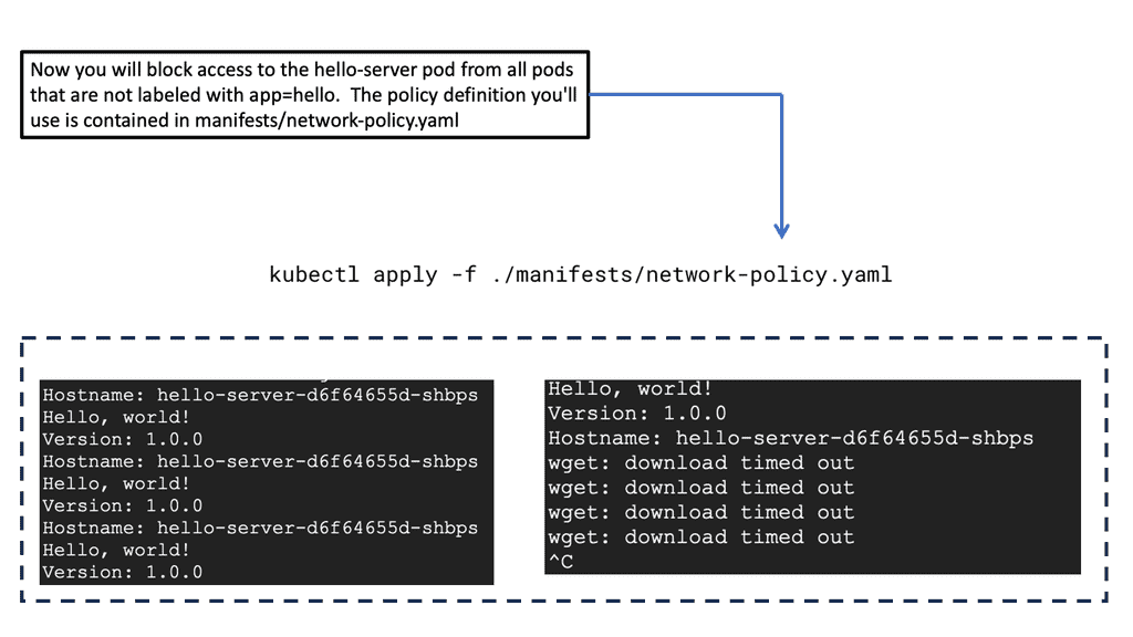
Its base topology has several mesh-type self-healing 6LoWPAN nodes connected to the Edge router for connectivity and integration to the Internet. The edge routers act as a bridge between the RF and Ethernet networks.

Closing Points on IoT Theory

To understand IoT theory, it’s essential to grasp the fundamental components that make it tick. The primary elements include sensors, connectivity, and data processing. Sensors are embedded in devices to collect data, which is then transmitted via various connectivity options such as Wi-Fi, Bluetooth, or cellular networks. Once the data reaches its destination, advanced processing systems analyze and interpret this information, leading to actionable insights. These building blocks create a seamless network of communication between devices, paving the way for smart solutions across industries.

The applications of IoT are vast and varied, extending across multiple sectors. In healthcare, IoT devices can monitor patients’ vital signs in real-time, ensuring timely intervention when necessary. In agriculture, sensors can track soil moisture levels and adjust irrigation systems accordingly, optimizing water usage. Meanwhile, in smart cities, IoT-powered infrastructure can improve traffic management and reduce energy consumption. These innovations demonstrate the transformative potential of IoT theory, driving efficiency and innovation in countless fields.

Despite its promising potential, IoT theory is not without its challenges. Security remains a top concern, as the proliferation of connected devices increases the risk of cyberattacks. Ensuring data privacy and protecting sensitive information are critical priorities for developers and users alike. Additionally, the sheer volume of data generated by IoT devices presents challenges in terms of storage and processing. Addressing these issues requires ongoing research and development to ensure the secure and efficient implementation of IoT solutions.

Summary: Internet of Things Theory

In this digital age, the Internet of Things (IoT) has become integral to our lives. IoT has revolutionized how we interact with technology, from smart homes to connected devices. In this blog post, we explored the various aspects of the Internet of Things and its impact on our daily lives.

What is the Internet of Things?

The Internet of Things refers to the network of interconnected devices and objects that can communicate and exchange data. These devices, equipped with sensors and connectivity, can range from smartphones and wearables to household appliances and industrial machinery. The IoT enables seamless communication and automation, making our lives more convenient and efficient.

Applications of the Internet of Things

The applications of IoT are vast and diverse. Smart homes, for instance, leverage IoT technology to control lighting, temperature, and security systems remotely. Healthcare systems also benefit from IoT, with wearable devices monitoring vital signs and transmitting real-time health data to healthcare professionals. Furthermore, industries are utilizing IoT to optimize production processes, track inventory, and enhance overall efficiency.

Challenges and Concerns

While the Internet of Things offers numerous advantages, it presents certain challenges and concerns. Security and privacy issues arise due to the vast amount of data being generated and transmitted by IoT devices. As more devices connect to the internet, the potential for cyber-attacks and data breaches increases. Additionally, the sheer complexity of managing and securing a large-scale IoT network poses a significant challenge.

The Future of IoT

The Internet of Things is poised for even more significant growth and innovation as technology advances. With the advent of 5G networks, the connectivity and speed of IoT devices will vastly improve, opening up new possibilities. Moreover, integrating artificial intelligence and machine learning with IoT promises smarter and more autonomous systems that can adapt to our needs.

Conclusion:

The Internet of Things has undoubtedly transformed how we live and interact with our surroundings. IoT has become an integral part of our digital ecosystem, from enhancing convenience and efficiency to driving innovation across industries. However, as we embrace this connected future, it is crucial to address security and privacy challenges to ensure a safe and trustworthy IoT landscape.

netyce

Automating Networks with netYCE

I recently completed a two-part post for notice on the challenges of Network Automation. Kindly click the link to view Part 1 – Matt Conran and netYCE. Part 2 – Matt Conran and netYCE

“Even with all the buzz and hype over the last few years circulating network automation, only a small proportion of customers seem to realize the true benefits of proper end-to-end network automation from both a business and technology standpoint. Looking closer, there is a crucial topic not addressed in the many discussions on network automation. It gets kicked to the side by the introduction of glossy technologies and vendor solutions. When you remove all the fancy ideas pushed by networking vendors and NFV/SDN evangelists and focus on the core automation challenge, we are talking about how to achieve network programmability with improved manageability.”

“There seems to be a common fear amongst network engineers when talking about network automation. This is understandable as network engineers understand the complexities and diversities of networking as no others. But if you adopt the approach that netYCE offers you, there is nothing to fear. In fact, it turns out to be risk-free, fully transparent, extremely powerful & scalable. This blog will explain How.”


ns1

NS1 – Adding Intelligence to the Internet

I recently completed a two-part guest post for DNS-based company NS1. It discusses Internet challenges and introduces the NS1 traffic management solution – Pulsar. Part 1, kindly click – Matt Conran with NS1, and Part 2, kindly click – Matt Conran with NS1 Traffic Management. 

Application and service delivery over the public Internet is subject to various network performance challenges. This is because the Internet comprises different fabrics, connection points, and management entities, all of which are dynamic, creating unpredictable traffic paths and unreliable conditions. While there is an inherent lack of visibility into end-to-end performance metrics, for the most part, the Internet works, and packets eventually reach their final destination. In this post, we’ll discuss key challenges affecting application performance and examine the birth of new technologies,multi-CDNN designs, and how they affect DNS. Finally, we’ll look at Pulsar and our real-time telemetry engine developed specifically for overcoming many performance challenges by adding intelligence at the DNS lookup stage.”


Kubernetes PetSets

Kubernetes Networking 101

Kubernetes Networking 101

Kubernetes, the popular container orchestration platform, has revolutionized the way applications are deployed and managed. However, for newcomers, understanding Kubernetes networking can be a daunting task. In this blog post, we will delve into the basics of Kubernetes networking, demystifying concepts and shedding light on how communication flows between pods and services.

In order to understand Kubernetes networking, it's crucial to grasp the concept of pods and nodes. Pods are the basic building blocks of Kubernetes, comprising one or more containers that work together. Nodes, on the other hand, are the individual machines in a Kubernetes cluster that run these pods. We'll explore how pods and nodes interact and communicate with each other.

Container Networking Interface (CNI): To enable communication between pods, Kubernetes relies on a plugin called the Container Networking Interface (CNI). This section will explain the role of CNI and how it facilitates networking in Kubernetes clusters. We'll also discuss popular CNI plugins like Calico, Flannel, and Weave, highlighting their features and use cases.

Service Discovery and Load Balancing: One of the key features of Kubernetes networking is service discovery and load balancing. Services act as an abstraction layer, providing a stable endpoint for accessing pods. We'll delve into how services are created, how they discover pods, and how load balancing is achieved to distribute traffic effectively.

Network Policies and Security: In a production environment, network security is of utmost importance. Kubernetes offers network policies to control traffic flow and enforce security rules. This section will cover how network policies work, how to define them, and how they can be used to restrict communication between pods or namespaces.

Kubernetes networking forms the backbone of a well-functioning cluster, enabling seamless communication between pods and services. By understanding the basics of pods, nodes, CNI, service discovery, load balancing, and network policies, you can unlock the full potential of Kubernetes. Whether you're just starting out or seeking to deepen your knowledge, mastering Kubernetes networking is a valuable skill for any DevOps engineer or Kubernetes enthusiast.

Highlights: Kubernetes Networking 101

## The Basics of Kubernetes Networking

At its core, Kubernetes networking ensures that your containers can communicate with each other and with the outside world. Each pod in Kubernetes is assigned its own IP address, and these addresses are used to set up direct communication paths. Unlike traditional networking, there are no port mappings required, and every pod can communicate with every other pod without any NAT (Network Address Translation). This flat networking model simplifies communication but comes with its own set of challenges and considerations.

## Network Policies: Controlling Traffic Flow

Kubernetes allows you to control the traffic flow to and from your pods using Network Policies. These policies act as a firewall for your Kubernetes cluster, enabling you to define rules that dictate how pods can communicate with each other and with external services. By default, all communications are allowed, but you can create Network Policies to restrict access based on security requirements. Implementing these policies is crucial for maintaining a secure and efficient Kubernetes environment.

## Service Discovery and Load Balancing

In Kubernetes, services are used to expose your applications to the outside world and to enable communication within the cluster. Each service is assigned a unique IP address and acts as a load balancer, distributing traffic across the pods in the service. Kubernetes provides built-in service discovery, making it easy to locate other services using DNS. This seamless integration simplifies the process of deploying scalable applications, ensuring that your services are always reachable and responsive.

## Advanced Networking: CNI Plugins and Ingress Controllers

For more advanced networking requirements, Kubernetes supports CNI (Container Network Interface) plugins. These plugins allow you to extend the networking capabilities of your cluster, providing additional features such as custom IPAM (IP Address Management) and advanced routing. In addition to CNI plugins, Ingress Controllers are used to manage external HTTP and HTTPS traffic, offering more granular control over how your services are exposed to the outside world. Understanding and configuring these advanced networking features is key to leveraging the full potential of Kubernetes.

Kubernetes Components

To comprehend Kubernetes networking, we must first delve into the world of Pods. A Pod represents the smallest unit in the Kubernetes ecosystem, encapsulating one or more containers. Despite sharing the same network namespace, each Pod possesses a unique IP address, enabling inter-Pod communication. However, it is crucial to understand how Pods communicate with each other within a cluster.

Services act as an abstraction layer, facilitating the discovery and load balancing of Pods. By defining a Service, developers can decouple applications from specific Pod IP addresses, as Services provide a stable endpoint for internal communication. Furthermore, Services enable external access to Pods through the use of NodePorts or LoadBalancers, making them an essential component for networking in Kubernetes.

Ingress, a powerful Kubernetes resource, allows for the exposure of HTTP and HTTPS routes to external traffic. By implementing Ingress, developers can define rules and routes, effectively managing inbound traffic to their applications. This flexible and scalable approach simplifies networking complexities and provides a seamless experience for end-users accessing Kubernetes services.

Kubernetes Clusters in GKE

#### Why Choose Google Cloud for Your Kubernetes Cluster?

Google Cloud offers a unique advantage when it comes to running Kubernetes clusters. As the original creators of Kubernetes, Google offers deep integration between Kubernetes and its cloud services. Google Kubernetes Engine (GKE) provides a fully managed Kubernetes service, allowing developers to focus more on building and less on managing infrastructure. With GKE, you get the benefit of automatic upgrades, patching, and scaling, all backed by Google’s robust infrastructure. This ensures high availability and security for your applications, making it an ideal choice for businesses looking to leverage Kubernetes without the operational overhead.

#### Setting Up Your Kubernetes Cluster on Google Cloud

Setting up a Kubernetes cluster on Google Cloud is a straightforward process, thanks to the streamlined interface and comprehensive documentation provided by Google. First, you need to create a Google Cloud project and enable the Kubernetes Engine API. After that, you can use the Google Cloud Console or the `gcloud` command-line tool to create a new cluster. Google Cloud provides various configuration options, allowing you to customize the cluster to fit your specific needs, whether that’s optimizing for cost, performance, or a balance of both.

#### Best Practices for Managing Kubernetes Clusters

Once your Kubernetes cluster is up and running, managing it effectively becomes crucial. Google Cloud offers several tools and features to help with this. It’s recommended to use Google Cloud’s monitoring and logging services to keep track of your cluster’s performance and health. Implementing automated scaling helps you handle varying workloads without manual intervention. Additionally, consider using Kubernetes namespaces to organize your resources efficiently, enabling better resource allocation and access control across your teams.

Google Kubernetes EngineUnderstanding Pods and Services

One of the fundamental building blocks of Kubernetes networking is the concept of Pods and Services. Pods are the smallest unit in the platform and house one or more containers. Understanding how Pods communicate with each other and external entities is crucial. On the other hand, services provide a stable endpoint for accessing a group of Pods. 

– Cluster Networking: A robust networking solution is required for Pods and Services to communicate seamlessly within a Kubernetes cluster. We’ll dive into the inner workings of cluster networking, discussing popular networking plugins such as Calico, Flannel, and Cilium. 

– Ingress and Load Balancing: Kubernetes offers Ingress and load-balancing capabilities when exposing applications to the outside world. In this section, we’ll demystify Ingress, its role in routing external traffic to Services, and how to configure it effectively. We’ll also explore load-balancing options to ensure optimal traffic distribution across Pods.

– Network Security and Policies: With the increasing complexity of modern applications, network security becomes paramount. Kubernetes provides robust mechanisms to enforce network policies and secure communication between Pods. We’ll discuss how to define and apply network policies effectively, ensuring only authorized traffic flows within the cluster.

**Kubernetes networking aims to solve the following problems**

  1. Container-to-container communications with high coupling
  2. A pod-to-pod communication system
  3. Communicating from a pod to a service
  4. External-to-service communications

A virtual bridge network is a private network that containers attach to in the Docker networking model. Containers are allocated private IP addresses, so containers running on different machines cannot communicate. Docker allows developers to proxy traffic across nodes by mapping host ports to container ports. Docker administrators, usually system administrators, avoid port clashes in this scenario. In Kubernetes networking, it is handled differently.

The Kubernetes Networking Model

Kubernetes’ native networking model is capable of supporting multi-host cluster networking. Pods can communicate with each other by default, regardless of their hosts. Kubernetes relies on the CNI project to comply with the following requirements:

  • Without NAT, all containers must be able to communicate with each other.
  • Containers and nodes can communicate without NAT.
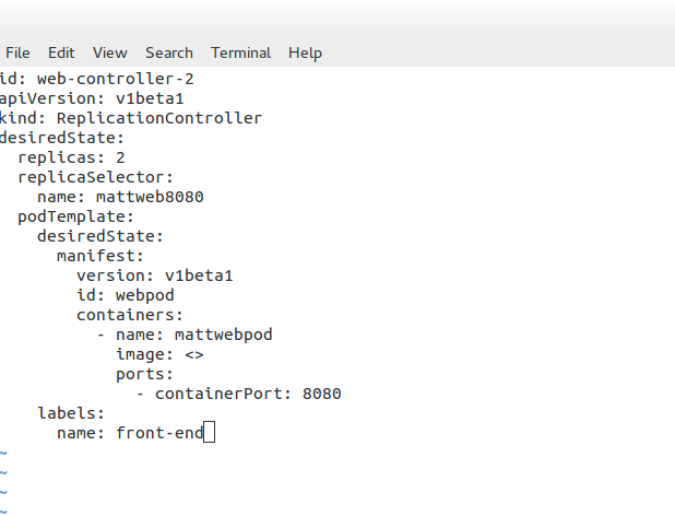
  • The IP address of a container matches the IP address of those outside the container.
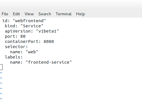
A pod is a unit of work in Kubernetes. Containers in pods are always scheduled and run “together” on the same node. It is possible to separate instances of a service into distinct containers using this connectivity. Developers may run services in one container and log forwarders in another. Having processes running in separate containers allows them to have separate resource quotas (e.g., “the log forwarder cannot use more than 512 MB of memory”). Reducing the scope necessary to build a container also separates container build and deployment machinery.

The Kubernetes History

Google released Kubernetes, an open-source cluster management tool, in June 2014. Google has said it launches over 2 billion containers per week, and Kubernetes was designed to control and manage the orchestration of all these containers and container networking. Initially, they built a Borg and Omega system, resulting in Kubernetes.

All lessons learned from Borg to Kubernetes are now passed to the open-source community. Kubernetes went 1.0 in July 2015 and is now at version 1.3.0. The Kubernetes deployment supports GCE, AWS, Azure, vSphere, and bare metal, and there are a variety of Kubernetes networking configuration parameters. Kubernetes forms the base for OpenShift networking

Kubernetes information check.

For additional information, before you go with Kubernetes networking 101, the post on Kubernetes chaos engineering discusses the need to stress and break a system, which is the only way to understand and optimize fully. Chaos Engineering starts with a baseline and introduces several controlled experiments. Then we have Kubernetes security best practice discuss the Kubernetes attack vectors and how to protect against them.

Understanding Pods & Service 

Before diving into deploying pods and services, it’s crucial to understand what a pod is within the context of Kubernetes. A pod is the smallest deployment unit in Kubernetes and can consist of one or more containers. Pods are designed to run a single instance of a specific application, sharing the same network and storage resources. By grouping containers, pods enable efficient communication and coordination between them.

Note: Deploying Pods

Now that we have a basic understanding of pods let’s explore the process of deploying one. To deploy a pod, you must create a YAML file describing its specifications, including the container image, resource requirements, and any necessary environment variables. Once the YAML file is created, you can use the `kubectl` command-line tool to apply the configuration and create the pod. It’s essential to verify the pod’s status using `kubectl get pods` and ensure it runs successfully.

While pods enable the deployment of individual containers, services expose these pods to the external world. Services act as an abstraction layer, allowing applications to communicate with pods without knowing their specific IP addresses or ports. Kubernetes offers various services, such as ClusterIP, NodePort, and LoadBalancer, each catering to different networking requirements.

Note: YAML File Specifications 

You must create another YAML file defining its specifications to deploy a service. This includes selecting the appropriate service type, specifying the target port and protocol, and associating it with the corresponding pod using labels. Once the YAML file is ready, you can use `kubectl` to create the service. By default, services are assigned a ClusterIP, which enables communication within the cluster. Depending on your needs, you may expose the service externally using NodePort or LoadBalancer.

Note: Kubernetes Scaling Abilities

One of Kubernetes’ key advantages is its ability to scale applications effortlessly. By adjusting the replica count in the deployment YAML file and applying the changes, Kubernetes automatically creates or terminates pods to maintain the desired replicas. Additionally, Kubernetes provides various commands and tools to monitor and manage deployments, allowing you to upgrade or roll back to previous versions easily.

Kubernetes Networking vs Docker Swarm

### Understanding Kubernetes Networking

Kubernetes, often hailed as the king of container orchestration, offers a robust and flexible networking model. At its core, Kubernetes assigns each pod its own IP address, providing a flat network structure. This means that Kubernetes does not require you to map ports between containers, simplifying communication. The Kubernetes network model supports various plugins through the Container Network Interface (CNI), allowing seamless integration with different cloud providers and on-premise systems. Moreover, Kubernetes supports complex networking policies, enabling fine-grained control over traffic flow and security.

### Docker Swarm’s Networking Simplicity

Docker Swarm, on the other hand, is known for its simplicity and ease of use. It provides an overlay network that enables services to communicate with each other across nodes seamlessly. Swarm’s networking is straightforward to set up and manage, making it appealing for smaller teams or projects with less complex networking needs. Docker Swarm also supports load balancing and service discovery out of the box. However, it lacks the extensive networking plugins and policy features available in Kubernetes, which might limit its scalability in larger, more complex environments.

### Performance and Scalability: A Comparative Analysis

When it comes to performance, both Kubernetes and Docker Swarm have their pros and cons. Kubernetes is designed for scalability, capable of handling thousands of nodes and pods. Its networking model is highly efficient, ensuring minimal latency in communication. Docker Swarm, while efficient for smaller clusters, might face challenges scaling to the level of Kubernetes. The simplicity of Swarm’s networking can become a bottleneck in environments that require more sophisticated networking configurations and optimizations. Thus, choosing between the two often depends on the scale and complexity of the deployment.

### Security Considerations

Security is a paramount concern in any networking setup. Kubernetes offers a range of security features, including network policies, secrets management, and role-based access control (RBAC). These features allow administrators to define and enforce security rules at a granular level. Docker Swarm, though simpler in its networking approach, provides basic security features such as mutual TLS encryption and node certificates. While adequate for many use cases, Swarm’s security features may not meet the needs of organizations with stricter compliance requirements.

Before you proceed, you may find the following posts helpful:

  1. OpenShift SDN
  2. Docker Default Networking 101
  3. OVS Bridge
  4. Hands-On Kubernetes

Kubernetes Networking 101

Google Cloud Data Centers

## Why Google Cloud for Kubernetes?

Google Cloud is a popular choice for running Kubernetes clusters due to its scalability, reliability, and integration with other Google Cloud services. Google Kubernetes Engine (GKE) allows users to quickly and easily deploy Kubernetes clusters, offering features like automatic scaling, monitoring, and seamless updates. With GKE, you can focus on developing your applications while Google handles the underlying infrastructure, ensuring your applications run smoothly.

## Setting Up Your First Kubernetes Cluster on Google Cloud

Deploying a Kubernetes cluster on Google Cloud involves several steps. First, you’ll need to set up a Google Cloud account and enable the Kubernetes Engine API. Then, using the Google Cloud Console or Cloud SDK, you can create a new Kubernetes cluster. Configuring your cluster involves selecting the appropriate machine types, defining node pools, and setting up networking and security policies. Once your cluster is set up, you can deploy applications, manage resources, and scale your infrastructure as needed.

## Best Practices for Managing Kubernetes Clusters

Effectively managing your Kubernetes clusters involves implementing several best practices. These include monitoring cluster performance using Google Cloud’s Stackdriver, automating deployments with CI/CD pipelines, and implementing robust security measures such as role-based access control (RBAC) and network policies. Additionally, regularly updating your clusters and applications ensures that you benefit from the latest features and security patches.

At a very high level, Kubernetes Networking 101 enables a group of hosts to be viewed as a single compute instance. The single compute instance, consisting of multiple physical hosts, is used to deploy containers. This offers an entirely different abstraction level to our single-container deployments.

Users start thinking about high-level application services and the concept of service design only. They are no longer concerned with individual container deployment, as the orchestrator looks after the deployment, scale, and management.

For example, if users specify to the orchestration system they want a specific type of application with defined requirements, now deploy it for me. The orchestrator manages the entire rollout, specifies the targeted hosts, and manages the container lifecycle. The user doesn’t get involved with host selection. This abstraction allows users to focus only on design and workload requirements – the orchestrator takes care of all the low-level deployment and management details.

Kubernetes Networking 101
Diagram: Kubernetes Networking 101

1. Pods:

Pods are the fundamental building blocks of Kubernetes. They consist of one or more containers that share a common network namespace. Each pod receives a unique IP address, allowing containers within the pod to communicate via localhost. However, communication between different pods requires additional networking components.

2. Services:

Services provide a stable and abstracted network endpoint to access a set of pods. By grouping pods based on a standard label, services ensure that applications can discover and communicate with each other seamlessly. Kubernetes offers four types of services: ClusterIP, NodePort, LoadBalancer, and ExternalName. Each service type caters to specific use cases, providing varying levels of accessibility.

3. Ingress:

Ingress is a Kubernetes resource that enables inbound connections to reach services within the cluster. It acts as a traffic controller, routing external requests to the appropriate service based on rules defined in the Ingress resource. Additionally, Ingress supports TLS termination, allowing secure communication with services.

Networking Concepts:

To comprehend Kubernetes networking fully, it is essential to grasp critical concepts that govern its behavior.

1. Cluster Networking:

Cluster networking refers to the communication between pods running on different nodes within a Kubernetes cluster. Kubernetes leverages various networking solutions, such as overlay networks and software-defined networking (SDN) to establish node connectivity. Popular SDN solutions include Calico, Flannel, and Weave.

2. DNS Resolution:

Kubernetes provides a built-in DNS service that enables easy discovery of services within the cluster. Each service is assigned a DNS name, which can be resolved to its corresponding IP address. This allows applications to communicate with services using their DNS names, enhancing flexibility and decoupling.

3. Network Policies:

Network policies define rules that dictate how pods communicate with each other. Administrators can enforce fine-grained access control and secure application traffic using network policies. Policies can be based on various criteria, such as IP addresses, ports, and protocols.

GKE Network Policies 

### Crafting Effective Network Policies

To create effective network policies, you must first grasp the structure and components that define them. Network policies in GKE are expressed in YAML format and consist of specifications that dictate how pods communicate with each other. This section will guide you through the essentials of crafting these policies, focusing on key elements such as pod selectors, ingress and egress rules, and the importance of defining explicit traffic paths.

### Implementing and Testing Your Policies

Once you have crafted your network policies, the next step is to implement and test them within your GKE environment. This section will provide a step-by-step guide on how to apply these policies and verify their effectiveness. We will cover common tools and commands used in testing, as well as strategies for troubleshooting and refining your policies to ensure they meet your desired outcomes.

### Best Practices for Network Policy Management

Managing network policies in a dynamic Kubernetes environment can be challenging. In this section, we’ll discuss best practices to streamline this process, including how to regularly audit and update your policies, integrate them with existing security frameworks, and utilize automation tools for enhanced management. Adopting these practices will help you maintain a secure and efficient network policy strategy in your GKE clusters.

Kubernetes network policy

Discussing Microservices

Distributed systems are more fine-grained now, with Kubernetes driving microservices. Microservices is a fast-moving topic involving the breaking down applications into many specific services. All services have their lifecycles, collaborating. Splitting the Monolith with microservices is not a new idea ( the term is ), but the emergence of new technologies has a profound effect.

The specific domains/containers require constant communication and access to each other’s services. Therefore, a strategy needs to be maintained to manage container interaction. For example, how do we scale containers? What’s the process for container failure? How do we react to container resource limits? 

Although Docker does help with container management, Kubernetes orchestration works on a different scale and looks at the entire application stack, allowing management at a service/application level.

We need a management and orchestration system to utilize containers’ and microservices’ portability fully. Containers can’t just be thrown into a sea of computing and expect to tie themselves together and work efficiently.

A management tool is required to govern and manage the life of containers, where they are placed, and to whom they can talk. Containers have a complicated existence, and many pieces are used to patch up their communication flow and management. We have updates, high availability, service discovery, patching, security, and networking. 

The most important aspect about Kubernetes or any content management system is that they are not concerned with individual container placement. Instead, the focus is on workload placement. Users enter high-level requirements, and the scheduler does the rest—where, when, and how many? 

Kubernetes networking 101 and network proximity.

Looking at workloads to analyze placement optimizes application deployment. For example, some processes that are part of the same service will benefit from network proximity. Front-end tiers sending large chunks of data to a backend database tier should be close to each other, not trombone across the network Kubernetes host for processing.

Likewise, when common data needs to be accessed and processed, it makes sense to put containers “close” to each other in a cluster. The following diagram displays the core Kubernetes architecture.

Kubernetes Networking 101: The Constructs

Kubernetes builds the application stack using four primary constructs: Pods, Services, Labels, and Replication Controllers. All constructs are configured and combined, creating a complete application stack with all management components—pods group similar containers on the same hosts.

Labels tag objects; replication controllers manage the desired state at a POD level, not container level, and services enable Pod-to-Pod communication. These constructs allow the management of your entire application lifecycle instead of individual application components. The construct definition is done through configuration files in YAML or JSON format.

The Kubernetes Pod

Pods are the smallest scheduling unit in Kubernetes and hold a set of closely related containers, all sharing fate and resources. Containers in a Pod share the same Kubernetes network namespace and must be installed on the same host. The main idea of keeping similar or related containers together is that processing is performed locally and does not incur any latency traversing from one physical host to another. As a result, local processing is always faster than remote processing. 

Pods essentially hold containers with related pieces of the application stack. The critical point is that they are ephemeral and follow a specific lifecycle. They should come and go without service interruption as any service-destined traffic directed should be towards the “service” endpoint IP address, not the Pod IP address.

Even Though Pods have a pod-wide-IP address, service reachability is carried out with service endpoints. Services are not as temporary ( although they can be deleted ) and don’t go away as much as Pods. They act as the front-end VIP to back-end Pods ( more on later ). This type of architecture hammers home the level of abstraction Kubernetes seeks.

Pod definition file

The following example displays a Pod definition file. We have basic configuration parameters, such as the Pod’s name and ID. Also, notice that the object type is set to “Pod.” This will be set according to the object we are defining. Later we will see this set as “service” for determining a service endpoint.

In this example, we define two containers – “testpod80” and “testpod8080”. We also have the option to specify the container image and Label. As Kubernetes assigns the same IP to the Pod where both containers live, we should be able to browse to the same IP but different port numbers, 80 or 8080. Traffic gets redirected to the respective container.

Kubernetes Pod

Kubernetes labels

Containers within a Pod share their network namespaces. All containers within can reach each other’s ports on localhost. This reduces the isolation between containers, but any more isolation would go against why we have Pods in the first place. They are meant to group “similar” containers sharing the same resource volumes, RAM, and CPU. For Pod segmentation, we have labels – a Kubernetes tagging system.

Labels offer another level of abstraction by tagging items as a group. They are essentially key-value pairs categorizing constructs. When we create Kubernetes constructs, we can set a label, which acts as a tag for that construct.

This means you can access a group of objects by specifying the label assigned to those objects. For example, labels distinguish containers as part of a web or database tier. The “selector” field tells Kubernetes which labels to use in finding Pods to forward traffic to.

Replication Controller

Container Scheduler

The replication controller ( RC ) manages the lifecycle and state of Pods. It ensures the desired state always matches the actual state. When you create an RC, you define how many copies ( aka replicas) of the Pod you want in the cluster.

The RC maintains that the correct numbers are running by creating or removing Pods at any time. Kubernetes doesn’t care about the number of containers running in a Pod; its only concern is the number of Pods. Therefore, it works at a Pod level.

The following is an example of an RC service definition file. Here, you can see that the desired state of replicas is “2.” A replica of 2 means that the number of pods each controller should maintain is 2. Changing the number up or down will either increase or decrease the number of Pods the replication controller manages.

For example, if the RC notices too many, it will stop some from returning the replication controller to the desired state. The RC keeps track of the desired state and returns it to the state specified in the service definition file. We may also assign a label for grouping replication controllers.

Kubernetes replication controller

Kubernetes Services

Service endpoints enable the abstraction of services and the ability to scale horizontally. Essentially, they are abstractions defining a logical set of Pods. Services represent groups of Pods acting as one, allowing Pods to access services in other Pods without directing service-destined traffic to the Pod IP. Remember, Pods are short-lived!

The service endpoint’s IP address is from the “Portal Net” range defined on the API service. The address is local to the host, so ensure it doesn’t clash with the docker0 bridge IP address.

Pods are targeted by accessing a service that represents a group of Pods. A service can be viewed with a similar analogy to a load balancer, sitting in front of Pods accepting front-end service-destined traffic. Services act as the main hooking point for service / Pod interactions. They offer high-level abstraction to Pods and the containers within.

All traffic gets redirected to the service IP endpoint, which redirects it to the correct backend. Traffic hits the service IP address ( Portal Net ), and a Netfilter IPtable rules forward to a local host high port number.

The proxy service creates a high port number, which forms the basis for load balancing. The load balancing object then listens to that port. The Kub proxy acts as a full proxy, maintaining two different TCP connections.

One separates the connection from the container to the proxy and another from the proxy to the load-balanced destination. The following is an example of a service definition file. The service listens on port 80 and sends traffic to the backend container port on 8080. Notice how the object kind is set to “service” and not “Pods” like in the previous definition file.

Kubernetes Services

Kubernetes Networking 101 Model

The Kubernetes networking model details that each Pod should have a routable IP address. This makes communication between Pods easier by not requiring any NAT or port mappings we had with earlier versions of Docker networking.

With Kubernetes, for example, we can have a web server and database server placed in the same Pod and use the local interface for cross-communication. Furthermore, there is no additional translation, so performance is better than that of a NAT approach.

Kubernetes network proxy

Kubernetes fulfills service -> Pods integration by enabling a network proxy called the Kube-proxy on every node in a cluster. The network proxy is always there, even if Pods are not running. Its main task is to route traffic to the correct Pod and can do TCP, UDP stream forwarding, or round-robin TCP, UDP forwarding.

The Kube proxy captures service-destination traffic and proxies requests from the service endpoint back to the application’s Pod. The traffic is forwarded to the Pods on the target port defined in the definition file, a random port assigned during service creation.

To make all this work, Kubernetes uses IPtables and Virtual IP addresses.

For example, when using Kubernetes alongside OpenContrail, the Kube-proxy is disabled on all hosts, and the OpenContrail router module implements connectivity via overlays ( MPLS over UDP encapsulation ). Another vendor on the forefront is Midokura, the co-founder behind OpenStack Project Kuryr. This project aims to bring any SDN plugin (MidoNet, Dragon flow, OVS, etc.) to Containers—more on these another time.

Kubernetes Pod-IP approach

The Pods IP address is reachable by all other Pods and hosts in the Kubernetes cluster. The address is not usually routable outside of the cluster. This should not be too much of a concern as most traffic stays within application tiers inside the cluster. Mapping external load-balancers achieves any inbound external traffic to services in the cluster.

The Pod-IP approach assumes that all Pods can reach each other without creating specific links. They can access each other by IP rather than through a port mapping on the physical host. Port mappings hide the original address by performing a masquerade – Source NAT.

Like your home residential router hides local PC and laptop IP addresses from the public Internet, cross-node communication is much simpler, as every Pod has an IP address. There isn’t any port mapping or NAT like there is with default docker networking. If the Kube proxy receives traffic for a Pod, not on its host, it simply forwards the traffic to the correct pod IP for that service.

The IP per POD offers a simplified approach to K8 networking. A unique IP per host would potentially need port mappings on the host IP as the number of containers increases. Managing port assignment would become an operational and management burden, similar to earlier versions of Docker. Conversely, a unique IP per container would surely hit scalability limits.

Kubernetes PAUSE container

Kubernetes has what’s known as a PAUSE container, also referred to as a Pod infrastructure container. It handles the networking by holding the networking namespace and IP address for the containers on that Pod. Some refer to the PAUSE container as an implementation detail you can safely ignore.

Each container uses a Pod’s “mapped container” mode to connect to the pause container. The mapped container mode is implemented with a source and target container grouping. The source container is the user-created container, and the target container is the infrastructure pause container.

Destination Pod IP traffic first lands on the pause container and gets translated to the backend containers. The pause container and the user-built containers all share the same network stack. Remember we created a service destination file with two containers – port 80 and port 8080? It is the pause container that listens on these port numbers.

In summary, the Kubernetes model introduces three methods of communication.

  • a) Pod-to-Pod communication directly by IP address. Kubernetes has a Pod-IP-wide metric simplifying communication.
  • b) Pod-to-Service Communication – Clients’ traffic is directed to the virtual service IP, which is then intercepted by the kub-proxy process ( running on all hosts) and directed to the correct Pod.
  • c) External-to-Internal Communication—External access is captured by an external load balancer that targets nodes in a cluster. The Kub proxy determines the correct Pod to send traffic to—more in a separate post.

Docker & Kubernetes networking comparison

Docker uses host-private networking. The Docker engine creates a default bridge, and every container gets a virtual ethernet to that bridge. The veth acts like a pipe – one end is mapped to the docker0 bridge namespace and the other to the container’s Linux namespace. This provides connectivity between containers on the same Docker bridge.

All containers are assigned an address from the 172.17.42.0 range and 172.17.42.1 to the default bridge acting as the container gateway. Any off-host traffic requires port mappings and NAT for communication. Therefore, the container’s IP address is hidden, and the network would see the container traffic coming from the docker nodes’ physical IP address. 

The effect is that containers can only talk to each other by IP address on the same virtual bridge. Any off-host container communication requires messy port allocations. Recently, there have been enhancements to docker networking and multi-host native connectivity without translations. Although there are enhancements to the Docker network, the NAT / Port mapping design is not a clean solution.

Docker Default networking
Diagram: Docker Default networking

The K8 model offers a different approach, and the docker0 bridge gets a routable IP address. Any outside host can access that Pod by IP address rather than through a port mapping on the physical host. Kubernetes has no NAT for container-to-container or container-to-node traffic.

Understanding Kubernetes networking is crucial for building scalable and resilient applications within a containerized environment. By leveraging its flexible architecture and components like Pods, Services, and Ingress, developers can enable seamless container communication and ensure efficient network management.

Moreover, comprehending network concepts like cluster networking, DNS resolution, and network policies empowers administrators to establish robust and secure communication channels within the Kubernetes ecosystem. Embracing Kubernetes networking capabilities unlocks the full potential of this powerful container orchestration platform.

Closing Points on Kubernetes Networking 101

At the heart of Kubernetes networking lies a flat network structure. This unique model ensures that every pod, a basic Kubernetes unit, can communicate with any other pod without NAT (Network Address Translation). This design principle simplifies communication processes, eliminating complex network configurations. However, achieving this simplicity requires comprehending core concepts such as Network Policies, Services, and Ingress, which facilitate and control internal and external traffic.

Services in Kubernetes act as an abstraction layer over a set of pods, providing a stable endpoint for client communication. As pods can dynamically scale or change due to Kubernetes’ orchestration, services ensure that there is a consistent way to access these pods. Services can be of different types, including ClusterIP, NodePort, and LoadBalancer, each serving unique roles and use cases. Understanding how to configure and utilize these services effectively is key to maintaining robust and scalable applications.

Network Policies in Kubernetes provide a mechanism to control the traffic flow to and from pods. They allow you to define rules that specify which connections are allowed or denied, enhancing the security of your applications. By leveraging Network Policies, you can enforce stringent security measures, ensuring that only authorized traffic can interact with your application components. This section will delve into creating and applying Network Policies to safeguard your Kubernetes environment.

Ingress in Kubernetes serves as an entry point for external traffic into the cluster, providing HTTP and HTTPS routing to services within the cluster. It offers functionalities such as load balancing, SSL termination, and name-based virtual hosting. Properly configuring Ingress resources is essential for directing external traffic efficiently and securely to your services. This section will guide you through setting up and managing Ingress controllers and resources to optimize your application’s accessibility and performance.

Summary: Kubernetes Networking 101

Kubernetes has emerged as a powerful container orchestration platform, revolutionizing how applications are deployed and managed. However, understanding the intricacies of Kubernetes networking can be daunting for beginners. In this blog post, we will explore its essential components and concepts and dive into the fundamentals of Kubernetes networking.

Understanding Pods and Containers

To grasp Kubernetes networking, it is essential to comprehend the basic building blocks of this platform. Pods, the most minor deployable units in Kubernetes, consist of one or more containers that share the same network namespace. We will explore how containers within a pod communicate and how they are isolated from other pods.

Cluster Networking

Cluster networking enables communication between pods and services within a Kubernetes cluster. We will delve into different networking models, such as overlay and host-based networking, and discuss how they facilitate seamless communication between pods residing on other nodes.

Services and Service Discovery

Services act as an abstraction layer that enables pods to communicate with each other, regardless of their physical location within the cluster. We will explore various services, including ClusterIP, NodePort, and LoadBalancer, and understand how service discovery simplifies connecting to pods dynamically.

Ingress and Load Balancing

Ingress controllers provide external access to services within a Kubernetes cluster. We will discuss how ingress resources and controllers work together to route incoming traffic to the appropriate services, ensuring efficient load balancing and traffic management.

Conclusion: Kubernetes networking forms the backbone of seamless communication between containers and services within a cluster. By understanding the fundamental concepts and components of Kubernetes networking, beginners can confidently navigate the complexities of this powerful orchestration platform.

rsz_docker_111

Docker Default Networking 101

Docker Default Networking 101

In the vast realm of containerization, Docker has emerged as a powerful tool for application deployment and management. One of the fundamental aspects of Docker is its default networking capabilities, which allow containers to communicate with each other and the outside world. In this blog post, we will dive deep into Docker's default networking, exploring its inner workings and shedding light on key concepts and considerations.

Docker's default networking is a built-in feature that enables containers to communicate seamlessly within a host and with external networks. By default, Docker creates a bridge network on each host, which acts as a virtual switch connecting containers. This bridge network allows containers to communicate with each other using IP addresses.

The Bridge Network and Its Components: Within the realm of Docker's default networking, the bridge network plays a crucial role. It serves as the default network for containers, providing isolation, IP address assignment, and name resolution. The bridge network also acts as a gateway for containers to connect to external networks.

Container Communication within the Bridge Network: Containers within the same bridge network can communicate with each other using their IP addresses. This enables seamless interaction between containers, facilitating the development of complex microservices architectures. Additionally, Docker provides the ability to assign custom names to containers, making communication more manageable and intuitive.

Bridging Containers with the External World: To enable communication between containers and external networks, Docker employs a technique called Network Address Translation (NAT). Through NAT, Docker maps container ports to host ports, allowing external systems to connect to specific containers. This bridging mechanism opens up possibilities for exposing containerized applications to the wider network.

Docker's default networking is a powerful feature that simplifies container communication and enables seamless integration with external networks. Understanding the bridge network and its components provides a solid foundation for building robust and scalable containerized applications. By delving into the intricacies of Docker's default networking, developers and system administrators can harness its capabilities to create dynamic and interconnected container ecosystems.

Highlights: Docker Default Networking 101

### Understanding Docker Networking Basics

Docker’s networking capabilities are one of its most powerful features, allowing containers to communicate with each other and the outside world. At its core, Docker provides users with a default networking setup that simplifies the process of managing container interactions. This default network ensures that containers can access each other and external networks effortlessly, making it an ideal starting point for beginners.

### Exploring Docker’s Bridge Network

When you install Docker, a default bridge network is created automatically. This network allows containers to communicate with each other using private IP addresses. By understanding how the bridge network operates, users can effectively manage container interactions without needing advanced networking knowledge. It acts as a virtual switch, connecting containers in a secure and isolated environment, which is perfect for testing and development purposes.

### Connecting Containers to External Networks

One of the most crucial aspects of Docker networking is connecting containers to external networks, such as the internet. Docker’s default network configuration allows containers to access external networks via Network Address Translation (NAT). This means that while your containers have private IP addresses, they can still initiate outbound connections to the internet, enabling updates, downloads, and communication with external services.

### Advanced Networking with User-Defined Networks

While Docker’s default networking is sufficient for many use cases, there are scenarios where you might need more control over your network configuration. Docker allows users to create custom networks with specific settings, such as defining subnets and IP address ranges. This flexibility is invaluable when building complex, multi-container applications that require specific network configurations for optimal performance and security.

Understanding Docker Default Networking

1 – Docker Default Networking is a built-in networking driver that allows containers to communicate with each other using a shared network. By default, Docker creates a bridge network named “bridge” and assigns it to newly created containers. This bridge network acts as a virtual switch, allowing containers to connect and communicate seamlessly.

2 – One of the key advantages of Docker Default Networking is its simplicity. With a few simple commands, containers can be connected to the default bridge network, enabling them to communicate with each other effortlessly. Moreover, Docker Default Networking provides isolation, as containers connected to the default bridge network are isolated from the host network, ensuring better security and preventing conflicts.

3 – To effectively utilize Docker Default Networking, it’s crucial to understand how to configure and manage it. Docker offers a range of commands and options to manage the default bridge network, including creating custom bridge networks, connecting containers to specific networks, and configuring IP addressing. We will explore these concepts in detail, providing step-by-step instructions and examples.

4 – While Docker Default Networking offers convenience, it’s important to follow best practices to ensure optimal performance and security. Some recommended practices include avoiding the use of the default bridge network for production deployments, creating custom bridge networks for better isolation, and utilizing container orchestration tools like Docker Compose to manage network configurations efficiently.

**Docker Architecture**

Docker is a powerful technology, which means both tools and processes are complex. From the user’s perspective, Docker has a simple client/server architecture despite its complex underpinnings. Several pieces make up the Docker API, including containerd and runc, but the basic interaction takes place over an API between a client and a server. Docker relies heavily on kernel mechanisms, including iptables, virtual bridging, Linux control groups (cgroups), Linux namespaces, secure computing mode, and various filesystem drivers, in addition to its simple appearance.

**Client/Server Model**

A Docker image, along with its metadata and images, is stored in the Docker registry. Using the client, you specify how containers should be built, run, and managed. Docker allows clients to address any number of servers, and the Docker daemon can run on any number. Clients interact directly with image registries when requested by Docker servers, but clients control all communication. Containerized applications are hosted and managed by servers, and clients control them.

docker client server module

Docker differs from some other client/server software in a few ways. The server orchestrates several components behind the scenes, including containerd-shim-runc-v2, which interfaces with runc, rather than being entirely monolithic. In most cases, Docker is just a simple client and server, hiding any complexity behind a simple API. It is common for Docker hosts to run one Docker server that is capable of managing any number of containers. To communicate with the server, the docker command-line tool can be used either from the server or, if properly secured, from a remote client.

Understanding Docker Networks

Docker networks provide a virtual bridge that connects containers, enabling communication between them. We will explore the various types of Docker networks, including the default bridge network, user-defined bridge networks, and overlay networks. Understanding these networks is essential for comprehending the nuances of Docker network connectivity.

Network Ports and Unix Sockets

A ) Dockerd and the command-line tool use Unix sockets and network ports to communicate. For docker daemons and clients, Docker, Inc., has registered three ports with the Internet Assigned Numbers Authority (IANA): TCP port 2375 for unencrypted traffic, TCP port 2376 for encrypted SSL connections, and TCP port 2377 for Docker Swarm mode.

B ) You can use a different port if you need different settings. By default, the Docker installer uses a Unix socket to communicate with the Docker daemon.

C ) Security is configured by default on the system. Due to the lack of user authentication and role-based access controls, Docker should not be used with network ports. Depending on the operating system, the Unix socket is usually located in /var/run/docker.sock.

D ) You can specify this at installation time or change it later by changing the server configuration and restarting the daemon if you have strong preferences. If you don’t, you might be able to get away with the defaults. You’ll save time and hassle if you don’t need to change the defaults.

Docker Orchestration

Understanding Docker Swarm

Docker Swarm, built upon the Docker Engine, allows you to create and manage a cluster of Docker nodes, forming a swarm. These nodes collaborate to run and scale applications across the swarm. With Docker Swarm, you can seamlessly distribute workloads, ensuring high availability and fault tolerance. The swarm manager acts as the control plane while the worker nodes execute the tasks the manager assigns.

One of Docker Swarm’s key advantages is its ability to effortlessly scale applications. By leveraging the swarm’s power, you can easily scale your services up or down based on demand. Docker Swarm intelligently distributes the workload across multiple nodes, ensuring efficient resource utilization. With its built-in load balancing and service discovery mechanisms, scaling becomes seamless and transparent.

Achieving Resilience with Docker Swarm

Resilience is crucial for modern applications, and Docker Swarm excels. By deploying services across multiple nodes, Docker Swarm ensures that the application continues without disruption, even if a node fails. The swarm manager automatically reschedules tasks on healthy nodes, maintaining the desired state of the application. This fault tolerance mechanism and automated health checks guarantee high availability for your services.

Apart from scalability and resilience, Docker Swarm offers a range of advanced features. It supports rolling updates, allowing you to update your services without downtime. Constraints and placement preferences enable you to control where services are deployed within the swarm. Additionally, Docker Swarm integrates with other Docker tools, such as Docker Compose, allowing you to define complex multi-container applications.

Docker Orchestration: Kubernetes

### Why Choose Google Cloud for Your Kubernetes Deployment?

Google Cloud offers a fully managed Kubernetes service called Google Kubernetes Engine (GKE), which simplifies the complex world of Kubernetes. GKE provides a powerful, scalable, and reliable platform that lets you focus on your applications rather than the underlying infrastructure. Its seamless integration with other Google Cloud services, such as Google Cloud Storage and BigQuery, enhances its capabilities, making it an attractive choice for businesses looking to leverage cloud-native architectures.

### Setting Up Your Kubernetes Cluster on Google Cloud

Setting up a Kubernetes cluster on Google Cloud is straightforward with GKE. Begin by creating a Google Cloud project and enabling the Kubernetes Engine API. The next step involves configuring your cluster settings, such as the number of nodes and machine types, through the Google Cloud Console or the gcloud command-line tool. GKE takes care of provisioning the necessary resources and deploying the cluster, allowing you to start deploying your applications within minutes.

### Optimizing Kubernetes Clusters for Performance and Cost

Once your cluster is up and running, optimizing it for performance and cost becomes crucial. Google Cloud offers tools like Stackdriver for monitoring and logging, which help in identifying bottlenecks and anomalies. Additionally, GKE’s autoscaling features ensure that your application can handle varying loads efficiently by automatically adjusting the number of nodes in your cluster. Implementing best practices for resource requests and limits, as well as leveraging preemptible VMs, can significantly reduce costs without sacrificing performance.

### Security Best Practices for Kubernetes on Google Cloud

Security is a top priority when operating Kubernetes clusters. Google Cloud provides several features to enhance the security of your clusters. Role-Based Access Control (RBAC) allows you to define fine-grained permissions, ensuring that users have only the access necessary for their roles. Network policies can be used to control traffic flow between pods, protecting sensitive data from unauthorized access. Regularly updating your clusters and using Google’s Container Registry for vulnerability scanning further bolster your security posture.

**The Starting Points**

Initially, application stacks consisted of per-application server deployments. Single applications require a dedicated server, wasting server resources. Physical servers were never fully utilized, requiring upfront Capex and ongoing Opex costs. Individual servers need management, maintenance, security patches, antivirus software, and licenses, all of which require human intervention and ongoing expenses.

Introducing Virtualization:

Virtualization systems and container based virtualization helped the situation by allowing the Linux kernel and operating systems to run on top of a virtualized layer using virtual machines (VM). The Linux Kernel and the use of namespace and control groups form the base for Docker container security and Docker security options.

**Understanding SELinux**

– SELinux, or Security-Enhanced Linux, is a security module integrated into the Linux kernel. It provides a mandatory access control mechanism beyond traditional discretionary access controls. SELinux enforces strict policies, defining what actions are allowed or denied for processes, files, and other system resources.

– Before delving into SELinux’s role in Docker networking security, it is essential to grasp the basics of Docker networking. Docker allows containers to communicate with each other through virtual networks, enabling seamless interaction. However, this convenience raises concerns about potential security vulnerabilities.

– SELinux plays a crucial role in mitigating security risks within Docker networking. By enforcing policies at the kernel level, SELinux restricts container actions and interactions, minimizing the potential for unauthorized access or malicious activities. It provides an additional layer of defense, complementing Docker’s built-in security features.

Before you proceed, you may find the following helpful:

  1. OVS Bridge
  2. Overlay Virtual Networks
  3. Container Networking


Docker Default Networking 101

Understanding Docker Default Network

Docker is software that runs on Linux and Windows. It creates, manages, and can even orchestrate containers. When most people speak about Docker, they’re guided to the technology that runs containers. However, there are at least three things to be mindful of when referring to Docker as a technology:

  1. The runtime
  2. The daemon (a.k.a. engine)
  3. The orchestrator

Docker runs applications inside containers, which must communicate over many networks. This means Docker needs networking capabilities. Fortunately, Docker has solutions for container-to-container networks and connecting to existing networks and VLANs. The latter is essential for containerized applications interacting with functions and services on external systems such as VMs and physical servers.

Guide on Docker Default Networking

In the following example, notice the IP assignment to Docker0 when we issue the ipconfig command on the docker host. So, this docker host is a Ubuntu server with a fresh install of Docker. The default network, which is “bridge,” has a subnet with the default gateway pointing to the docker0

Docker0 is a virtual Ethernet bridge that serves as Docker’s default bridge network interface. It is created automatically when Docker is installed on a host machine. The docker0 bridge is a central point for communication between containers, allowing them to connect and share information.

Docker0 plays a vital role in container networking by providing a default bridge network for containers to connect. When a container is created, it is attached to the docker0 bridge by default, allowing it to communicate with other containers on the same bridge. This default bridge network enables containers to access the host machine and external networks.

Docker Default networking
Diagram: Docker Default networking

Docker Default Networking:

When a container is created, Docker assigns it a unique IP address and adds it to a default network called “bridge.” The bridge network driver is the default networking driver used by Docker, providing a private internal network for the containers running on the same host. This default networking setup allows containers to communicate with each other using IP addresses within the bridge network.

Container Communication:

Containers within the same bridge network can communicate with each other using their respective IP addresses. Docker automatically assigns a hostname to each container, making it easy to reference and establish communication between containers. This seamless communication between containers is crucial for building microservices architectures, where different containers work together to deliver a complete application.

Exposing Container Ports:

By default, containers within the bridge network can communicate with each other, but they are isolated from the outside world. Docker provides port mapping functionality to expose a container’s services to the host or external networks. With port mapping, you can bind a container’s port to a specific port on the host machine, allowing external systems to access the container’s services.

Container Isolation:

One of Docker’s key features is container isolation, which ensures that containers running on the same host do not interfere with each other. Docker achieves this isolation by assigning unique IP addresses to each container and restricting network access between containers unless explicitly configured. This isolation prevents conflicts and ensures the smooth operation of applications running inside containers.

Custom Networking with Docker:

While Docker’s default networking is sufficient for most use cases, there are scenarios where custom networking configurations are required. Docker provides various networking options that allow you to create custom networks, such as overlay networks for multi-host communication, macvlan networks for assigning MAC addresses to containers, and host networks where containers share the host’s network stack. These advanced networking features offer flexibility and cater to complex networking requirements.

Bridge Network Driver:

By default, Docker uses the bridge network driver, which creates a virtual network bridge on the host machine. This bridge allows containers to communicate with each other and the outside world. Containers within the same bridge network can communicate with each other using their IP addresses or container names.

Understanding Container Connectivity:

When a container is started, it is automatically connected to the default bridge network. Containers on the same bridge network can communicate with each other using their IP addresses or container names. Docker also assigns each container a hostname, making it easier to refer to them within the network.

Exposing Container Ports:

Docker allows you to expose specific container ports to the host machine or the outside world. This is achieved by mapping the container port to a port on the host machine. Docker assigns a random port on the host machine by default, but you can specify a specific port if needed. This enables external access to services running inside containers.

Container Isolation:

Docker default networking provides isolation between containers by assigning each container a unique IP address. This ensures that containers can run independently without interfering with each other. It also adds a layer of security, as containers cannot access each other’s resources by default.

Custom Networks:

While Docker default networking is suitable for most scenarios, Docker also allows you to create custom networks with your desired configurations. Custom networks provide more control over container communication and will enable you to define network policies, assign IP addresses, and manage DNS resolution.

**The Virtualization Layer**

The virtualization layer holding the VM is called the Hypervisor. The VM / Hypervisor approach enables multiple applications to be installed on the same server, which is better for server resources. The VM has no idea. It shares resources with other VMs and operates like a physical server.

Compute virtualization brings many advantages to IT operations and increases the flexibility of data centers. However, individual applications still require their operating system, which is pretty resource-heavy. A new method was needed, and the container with container networking came along.

The hypervisor method gives each kernel distinct resources and defined entry points into the host’s physical hardware. Containers operate differently because they share the same kernel as the host system. You don’t need an operating system as a whole for each application, resulting in one less layer of indirection and elements to troubleshoot when things go wrong.

Docker default networking 101
Diagram: Docker default networking 101

Knowledge check for container Orchestration

Within the native multi-host capabilities, we need an orchestrator. There are two main ones, Kubernetes and Docker Swarn. Both Kubernetes network namespace and Docker Swarm create what is known as a cluster.

A cluster consists of Docker hosts acting as giant machines and Swarm or Kubernetes schedules based on resources. Swarm or Kubernetes presents a single interface to the Docker client tool, with groups of Docker hosts represented by a container cluster.

Containers – Application Philosophy

Linux containers challenge application philosophy. Many isolated applications now share the underlying host operating system. This was leap years better than a single application per VM, maximizing server resources. Technology has a crazy way of going in waves; for containers, we see old technologies revolutionizing applications.

Containers have been around for some time but were initially hindered by layers of complexity. Initially, we had batch processing systems, chroot system calls, Jails, Solaris Zones, Secure Resource Partition for HP-UX, and Linux containers in kernel 2.6.24. Docker is not alone in the world of containers.

Solomon Hykes, the founder and CEO of dotCloud, introduced Docker in 2013. Prior to this, few people outside had played with it. Docker containers completely reshape the philosophy of application delivery and development.

Under the hood, this is achieved by leveraging Linux IPtables, virtual bridges, Linux namespace, cgroupsoverlay networking, and filesystem-based portable imagesBy shrinking all dependencies to individual container images, the application footprint is reduced to megabytes, not gigabytes experienced with the VM.

A key point: Containers are lightweight

Containers are incredibly lightweight, and an image may only take 10 kilobytes of disk space. They are certainly the way forward, especially when it comes to speed. Starting a container takes milliseconds, not seconds or minutes. This is considerably faster than what we have with VMs.

We are not saying the VM is dead, but containers represent a fundamental shift in application consumption and how IT teams communicate. They are far more resource-efficient and can now be used for stateful and stateless services.

**Stateful and Stateless Applications**

Docker default networking works for both stateful and stateless applications. Initially, it was viewed as a tool for stateless applications, but now, with Dockers’ backend plugin architecture, many vendors’ plugins allow the containerization of stateful services. Stateful applications hold state and keep track of data in memory, files, or a database. Files and data can be mounted to a volume of 3rd party solutions. Stateless applications don’t keep track of information between requests.

An example of a stateless application is a web front end passing requests to a backend tier. If you are new to Docker and the container philosophy, it might be better to start with stateless applications. However, the most downloaded images from the docker hub are stateful.

You might also be interested in learning that Docker Compose is a tool for running multi-container applications on Docker that are defined using the Compose file format. A Compose file defines how one or more containers that make up your application are configured. 

While the VM and container achieve the same goal of supporting applications, their use case and practicality differ. Virtual machines are often long-lived in nature and slower to boot. Containers are ephemeral, meaning they come and go more readily and are quick to start.

VM is especially useful for hot migrations and VMotion, where TCP sessions must remain intact. We don’t usually use VMotion containers, but I’m sure someone somewhere is doing this—Brent Salisbury. Containers might only exist for a couple of seconds.

For example, it starts due to a user-specific request, runs some code to a backend, and then is destroyed. This does not mean that all applications are best suited for containers. VM and containerized applications are married and will continue to live with each other for another while.

Docker Default Networking 101

Initially, Docker default networking was only suited for single-host solutions employing Network Address Translation ( NAT ) and Port Mapping techniques for any off-host communication. Docker wasn’t interested in solving the multi-hosts problem as other solutions; for example, Weave overlays tried to solve this.

The default Docker networking uses multiple containers on a host with a single IP address per host. NAT and IPtables enable forwarding an outside port to an inside container port—for example, external port 5050 on Host1 maps to internal port 80 on Container1.

Therefore, the external connection to port 5050 is directed to port 80 on Container 1. We have to use NAT/port mapping because the host only has one IP address, and multiple containers live behind this single IP address. 

Bridged Network Mode

By default, the docker engine uses bridged network mode. Each container gets its networking stack based on the Linux NET namespace. All containers connecting to the same bridge on the host can talk freely by IP address.

Communicating with another Docker host requires special tricks with NAT and port mappings. However, recent Docker releases are packaged with native multi-host support using VXLAN tunnels, as discussed later. Here, we don’t need to use port mappings for host-to-host communication; we use overlays.

The diagram below shows a simple container topology consisting of two containers connected to the same docker0 bridge. The docker0 bridge acts as a standard virtual switch and passes packets between containers on a single host. It is the heart of all communication between containers.

Docker Networking 101 and the Docker Bridge

The docker0 bridge will always have an IP address of 172.17.42.1; containers are assigned an IP from this subnet. The 172.17.42.1 is the container’s default gateway. By default, all container networks are hidden from the underlay network. As a result, containers on different Docker hosts can use the same IP address. Virtual Ethernet Interfaces ( veth ) connect the container to the bridge.

In the preceding diagram, veth Eth0 is in the container namespace, and the corresponding vethxxxx is in the docker0 namespace. Linux namespaces provide that network isolation. The veths is like a pipe – what goes in one end must come out the other.

The default operation allows containers to ping each other and access external devices. Docker defaults don’t give the container a public IP address, so the docker0 bridge acts like a residential router for external access. The port mapping and NAT process has been used for external access, i.e., the host IP tables port masquerade ( aka performs Source NAT ).

Docker Flags

The docker0 bridge can be configured with several flags ( listed below ). The modes are applied at a container level so that you may see a mixture on the same docker host.

  • The –net default mode is the default docker0 bridge mode. All containers are attached to the docker0 bridge with a veth.
  • The –net=none mode puts the container in an isolated environment. The container has its network stack without any network interfaces. If you analyze the IP configuration on the container, it doesn’t display any interfaces, just a default loopback of 127.0.0.1.
  • The –net=container:$container2 mode shares the container’s namespaces. It may also be called a “container in a container .”When you run the second container, the network mode should be set to ‘container’ and specify the container we want to map. All the port mapping is carried out on the first container. Any changes to the port mapping config on the second container have no effect. During the link operation, the docker engine creates container host entries for each container, enabling resolution by name. The most important thing to remember about linking containers is that it allows for access to the linked container on an exposed port only; communication is not freely by IP.
  • The—-net=host mode shares the host’s namespace. The container doesn’t get an IP from the 172.17.0.0/16 space but uses the IP address of the actual host. The main advantage of the host mode is the native performance for high-throughput network services. Containers in host mode should experience a higher level of performance than those traversing the docker0 bridge with IPtable functions. However, it would help if you were careful about allocating port assignments. If ports are already bound, you cannot use them again. 

Docker default networking 101 and container communication.

Even though the containers can cross-communicate, their network stack is in isolation. Their networks are hidden from the underlay. The host’s IPtables perform masquerade for all container traffic for outbound communication. This enables the container to initiate communication to the outside but not the other way – from outside to inside.

Similar to how Source NAT works. To enable outside initiation to an inside container, we must carry out port mappings – map the external reachability port on the host’s network stack to a local container port.

For example, we must map some ports if container A on host 1 wants to talk to anything outside the host one docker0 bridge. Each container has its network namespace in a single host scenario and is attached to the network bridge. Here, you don’t need port mapping. You only need port mapping to expose the container to an external host.

Communication among containers on the same host is enabled via the docker0 bridge. Traffic does not need to trombone externally or get natd, etc. If you have two containers, A and B, connected to the same bridge, you can PING and view each other’s ARP tables.

Containers connected to the same bridge can communicate on any port they like, unlike the “linked” container model with exposed ports. The linking mode only permits communication on exposed ports—as long as the Inter Container Communication ( ICC ) is true.

The ICC value can be changed in ‘/etc/sysconfig/docker. If you set the ICC to false and require two containers to communicate on the same host, you must link them. Once connected, the containers can talk to each other on the container’s exposed ports ONLY. Just because you link containers doesn’t mean they can ping each other.

Linking also gives names of offers and service resolutions. More recently, in Docker 1.9, the introduction of user-defined networks ( bridge and overlay drivers ) uses an embedded DNS server instead of mapping IP to names in host files. This enables the pinging of containers by name without linking them together.

Multi-host connectivity

Initially, they tried to solve multi-host capability by running Open vSwitch at the edges of the hosts. Instead of implementing a central controller, for example, an OpenDaylight SDN controller, they opted for a distributed controller.

Socketplane employed a distributed control plane with VXLAN and Open vSwitch for data forwarding. They experimented with many control planes but used SURF – a gossip protocol. SURF is an application-centric way of distributing states across a cluster of containers.

It’s relatively fast, scales, and is eventually consistent. Similar to routing protocols, SURF would, for example, map the remote VXLAN ID to the IP Next hop and MAC address. They use a key-value store for consistent management functionality ( Consul, Etcd, and ZooKeeper ).

A key-value store is a data storage paradigm; for example, it handles the VXLAN ID. Its role is to store and hold information about discovery, networks, endpoints, and IP addresses; the other type of user-defined network, “bridge,” does not require a key-value store.

Socketplane introduced an Open vSwitch data plane, VXLAN overlay, and distributed control plane, which made Docker natively support multi-host connectivity without the mess of NAT and port mappings. I believe they have now replaced Open vSwitch with Linux Bridge. Communicating externally to the cloud would require port mappings / NAT, but anything between docker hosts doesn’t need this.

User-defined networks – Bridge and overlay

User-defined networks were a significant addition to Docker 1.9. Docker introduced a “bridge driver” and an “overlay driver .”As you might expect, the bridge driver allows the creation of user-defined bridge networks, working similarly to the docker0 bridge.

The overlay driver enables multi-host connectivity. Configuration is now done with the “docker network” command, which provides more scope for configuration. For example, bypassing the ‘-internal’ flag prevents external communication from the bridge, i.e., restricts containers attached to the bridge from talking outside the host.

The Docker overlay driver supports out-of-the-box multi-host container connectivity. The overlay driver creates a new “docker gw bridge” bridge on each host. This bridge can map host ports to internal container ports that are members of the overlay network. This is used for external access, not host-to-host, as this is done via overlays.

The container now has two interfaces, one to the overlay and one to the gateway bridge.

You can include the “internal” flag during creation to prevent external connectivity to the container. Passing this flag prevents the container from getting an interface to the new “docker gw bridge.” The bridge, however, still gets created.

So now we have an internal overlay setup with the internal flag; all docker containers can communicate internally via VXLAN. We can remove the “internal” flag and configure port mapping on the docker gw bridge to enable external connectivity.

Or we can use an HAProxy container and connect to the native docker0 bridge. This will accept and direct external front-end requests to backend containers according to the load-balancing algorithm selected. Check out Jon Langemak’s posts on user-defined networks and HAProxy

Closing Points on Docker Default Networking 

By default, Docker uses a bridge network named `bridge`. This network acts as a private internal network for containers running on the same host. When a container is launched without specifying a network, Docker automatically connects it to this default bridge network. This setup allows containers to communicate with each other using their IP addresses or container names. However, it’s important to note that this network is isolated from the host machine and external networks, providing a layer of security.

Another networking option available in Docker is the host network mode. When a container is run in this mode, it shares the network stack of the host system. This means that the container can directly use the host’s network interfaces and IP address. While this can result in higher performance due to reduced overhead, it comes with security trade-offs as the container is not isolated from the host network.

Port mapping is a key concept in Docker networking that allows services running inside a container to be accessible from outside the host. By default, Docker does not expose any container ports to the host. To make a service accessible, you need to publish a container’s port to the host using the `-p` flag when starting the container. For example, `docker run -p 8080:80` maps port 80 in the container to port 8080 on the host, making the service available at `localhost:8080`.

Docker Compose simplifies the process of managing multi-container applications by allowing you to define and run them using a single YAML file. When using Docker Compose, each service is connected to a default network that is isolated from other applications. This default network provides automatic DNS resolution, which enables services to discover each other by name. Docker Compose also allows you to define custom networks, giving you more control over the network topology of your applications.

Summary: Docker Default Networking 101

Docker has revolutionized the way we develop and deploy applications, and one of its key features is its default networking capability. In this blog post, we will explore Docker’s default networking, exploring its benefits, configuration options, and best practices. So, fasten your seatbelts as we embark on this exciting journey!

Understanding Docker Default Networking

Docker default networking is the built-in networking solution that allows containers to communicate seamlessly with each other and with the external world. By default, Docker assigns a unique IP address and a hostname to each container, enabling easy connectivity and interaction.

Benefits of Docker Default Networking

The default networking in Docker provides several advantages. Firstly, it simplifies the process of container communication, eliminating the need for complex manual configurations. Secondly, it offers isolation, ensuring that containers operate independently without interfering with each other. Lastly, it facilitates scalability, allowing the easy addition or removal of containers without disrupting the overall network.

Configuring Docker Default Networking

Although Docker default networking is automatic, it is essential to understand the different configuration options available. Docker provides bridge, overlay, and host networks, each serving specific purposes. We will explore these options in detail, discussing their use cases and how to configure them effectively.

Best Practices for Docker Default Networking

To maximize Docker default networking, it is crucial to follow some best practices. First, user-defined networks should be created for group-related containers, enhancing clarity and organization. Second, leverage Docker Compose to simplify the management of multi-container applications. Additionally, utilize network segmentation and firewall rules to ensure proper security measures.

Conclusion: In conclusion, Docker default networking is a powerful feature that enhances the connectivity and scalability of containerized applications. Understanding its fundamentals, benefits, and configuration options is essential for maximizing Docker’s potential in your development and deployment workflows. So, embrace the wonders of Docker default networking and unlock a world of possibilities!

Neutron Network

Neutron Network

In today's interconnected world, the importance of a robust and efficient network infrastructure cannot be emphasized enough. One technology that has been making waves in the networking realm is Neutron Network. In this blog post, we will delve into the intricacies of Neutron Network and explore its potential to bridge the digital divide.

Neutron Network, a component of OpenStack, is a software-defined networking (SDN) project that provides networking capabilities as a service for other OpenStack services. It enables the creation and management of virtual networks, routers, and security groups, offering a flexible and scalable solution for network infrastructure.

Neutron Network offers a wide range of features that make it an ideal choice for modern network deployments. From network segmentation and isolation to load balancing and firewall services, Neutron Network empowers administrators with granular control and enhanced security. Additionally, its integration with other OpenStack components allows for seamless management and orchestration of the entire infrastructure.

The versatility of Neutron Network opens up a plethora of use cases across various industries. In the realm of cloud computing, Neutron Network enables the creation of virtual networks for tenants, ensuring isolation and security. It also finds applications in data centers, enabling efficient traffic routing and load balancing. Moreover, with the rise of edge computing, Neutron Network plays a crucial role in connecting distributed devices and facilitating real-time data transfer.

While Neutron Network offers a plethora of advantages, it is essential to acknowledge and address the challenges it may pose. Some common limitations include complex initial setup, scalability concerns, and potential performance bottlenecks. However, with proper planning, optimization, and ongoing development, these challenges can be mitigated, ensuring a smooth and efficient network infrastructure.

Neutron Network emerges as a powerful tool in bridging the digital divide, empowering organizations to build robust and flexible network infrastructures. With its extensive features, seamless integration, and diverse applications, Neutron Network paves the way for enhanced connectivity, improved security, and efficient data transfer. Embracing this technology can unlock new possibilities and propel businesses into the future of networking.

Highlights: Neutron Network

Understanding Neutron Network

Neutron Network is an open-source networking project that provides networking services to virtual machines and containers within an OpenStack environment. It serves as the networking component of OpenStack, enabling users to create and manage networks, subnets, routers, and security groups. By abstracting the underlying network infrastructure, Neutron Network offers flexibility, scalability, and simplified network management.

Neutron Network boasts an impressive array of features that empower users to build robust and secure networks. Some of its key features include:

1. Network Abstraction: Neutron Network allows users to define and manage networks using a variety of network types, such as flat, VLAN, VXLAN, or GRE. This flexibility enables seamless integration with existing network infrastructure.

2. Security Groups: With Neutron Network, users can define security groups and associated rules to control traffic flow and enforce security policies. This granular level of security helps protect workloads from unauthorized access and potential threats.

3. Load Balancing: Neutron Network offers built-in load balancing capabilities, allowing users to distribute traffic across multiple instances. This ensures high availability, scalability, and optimal performance for applications and services.

Neutron Network finds application in various scenarios, catering to a wide range of use cases. Some notable use cases include:

1. Multi-Tenant Environments: Neutron Network enables the creation of isolated networks for different tenants within an OpenStack cloud. This segregation ensures secure and independent network environments, making it ideal for service providers and enterprises with multiple clients.

2. NFV (Network Function Virtualization): Neutron Network plays a crucial role in NFV deployments, where network functions are virtualized. It facilitates the creation and management of virtual network functions (VNFs), enabling efficient network service delivery and orchestration.

The need for virtual networking

A: ) Due to the proliferation of devices in data centers, today’s networks contain more devices than ever. Servers, switches, routers, storage systems, and security appliances are now available as virtual machines and virtual network appliances. A scalable, automated approach is needed to manage next-generation networks. Thanks to its flexibility, control, and provisioning time, users can control their infrastructure more easily and quickly with OpenStack.

B: ) OpenStack Networking is a pluggable, scalable, API-driven system that manages networks and IP addresses on OpenStack clouds. Like other core OpenStack components, It allows users and administrators to maximize the value and utilization of existing data center resources. Unlike Nova (computing), Glance (images), Keystone (identity), Cinder (block storage), or Horizon (dashboard), Neutron (Networking) is a stand-alone service. To provide resiliency and redundancy, OpenStack Networking can be configured to run on a single server or distributed across multiple hosts.

C: ) With OpenStack Networking, users can request additional processing through an application programmable interface or API. Cloud operators can enhance and power the cloud by defining network connectivity with different networking technologies. Access to a database is required for Neutron to store network configurations persistently.

Understanding Open vSwitch

Open vSwitch, often called OVS, is a multi-layer virtual switch that enables network automation and virtualization. It is designed to work seamlessly with hypervisors, containers, and cloud environments, providing a flexible and scalable networking solution. By integrating with various virtualization technologies, Open vSwitch allows for efficient network traffic management, ensuring optimal performance and reliability.

Features and Benefits of Open vSwitch

Open vSwitch offers an array of features that make it a preferred choice for network administrators and developers. Some key features include support for standard management interfaces, virtual and physical network integration, VLAN and VXLAN support, and flow-based forwarding. Additionally, OVS supports advanced features like Quality of Service (QoS), network slicing, and load balancing, empowering network operators to create dynamic and efficient networks.

OVS Use Cases

Open vSwitch finds applications in a wide range of use cases. One prominent use case is network virtualization, where OVS enables the creation of virtual networks isolated from the physical infrastructure. This allows for better resource utilization, enhanced security, and simplified network management.

OVS is also extensively used in cloud environments, facilitating seamless connectivity and virtual machine migration across data centers. Furthermore, Open vSwitch is leveraged in Software-Defined Networking (SDN) deployments, enabling centralized network control and programmability.

**Application Program Interface**

Neutron’s pluggable application program interface ( API ) architecture enables the management of network services for container networking in public or private cloud environments. The API allows users to interact with neutron networking constructs, such as routers and switches, enabling instance reachability. The OpenStack Neutron and OpenStack network types were initially built into Nova but lacked flexibility for advanced designs. It was helpful for large Layer 2 networks, but most environments require better multi-tenancy with advanced load balancing and firewalling functionality.

**Decoupled Layer 3 Approach**

The limited networking functionality gave Neutron, which offers a decoupled Layer 3 approach. It operates an Agent-Database model where the API receives and sends calls to agents installed locally on the hosts. Without this efficiency, there won’t be any communication and connectivity between your host’s platforms, which can sometimes affect productivity.

For additional pre-information, you may find the following helpful:

  1. OpenStack Neutron Security Groups
  2. Kubernetes Network Namespace
  3. Service Chaining

Neutron Network

Understanding Neutron’s Architecture

Neutron’s architecture is designed to be highly modular and pluggable, allowing operators to choose from a wide array of network services and plugins. At its core, Neutron consists of several components, including the Neutron server, plugins, and agents. The Neutron server is responsible for managing the high-level network state, while plugins handle the actual configuration of the low-level networking details across different technologies. Agents work as the intermediaries, ensuring that the network state is correctly applied to the physical or virtual network infrastructure.

**Advantages of Using Neutron in OpenStack**

Neutron provides several advantages for cloud administrators and users. Its modular architecture allows for flexibility and customization to meet the specific networking needs of different organizations. Additionally, Neutron supports advanced networking features such as security groups, floating IPs, and VPN services, which enhance the security and functionality of cloud deployments. By utilizing Neutron, organizations can efficiently manage their network resources, ensuring high availability and performance.

**Challenges and Considerations**

While Neutron offers numerous benefits, it also presents some challenges. Configuring and managing Neutron can be complex, especially in large-scale deployments. It’s essential to have a deep understanding of networking concepts and OpenStack’s architecture to avoid potential pitfalls. Additionally, integrating Neutron with existing network infrastructure may require careful planning and coordination.

Key Features and Benefits:

1. Network Virtualization: Neutron Network leverages network virtualization technologies such as VLANs, VXLANs, and GRE tunnels to create isolated virtual networks. This allows tenants to have complete control over their network resources without interference from other tenants.

2. Scalability: Neutron’s distributed architecture can scale horizontally to accommodate many virtual networks and instances. This ensures that cloud environments can handle increased workloads without compromising performance.

3. Network Segmentation: Neutron Network supports network segmentation, allowing tenants to partition their virtual networks based on specific requirements. This enables better network isolation, security, and performance optimization.

4. Flexible Network Topologies: Neutron provides the flexibility to create a variety of network topologies, including flat networks, VLAN-based networks, and overlay networks. This adaptability empowers users to design their networks according to their unique needs.

5. Integration with Security Services: Neutron Network integrates seamlessly with OpenStack’s security services, such as Firewall-as-a-Service (FWaaS) and Virtual Private Network-as-a-Service (VPNaaS). This integration enhances network security by providing additional layers of protection.

6. Load Balancing and VPN Services: Neutron Network offers load balancing services, allowing users to distribute network traffic across multiple instances for improved performance and reliability. Additionally, it supports VPN services to establish secure connections between different networks or remote users.

Neutron Network Architecture:

Under the hood, Neutron Network consists of several components working together to provide a robust networking service. The main elements include:

– Neutron API: Provides a RESTful API for users to interact with Neutron Network and manage their network resources.

– Neutron Core Plugin: The central component responsible for handling network-related requests and managing network plugins.

– Neutron Agents: Various agents, such as the DHCP agent, L3 agent, and OVS agent, ensure the smooth operation of the Neutron Network by handling specific tasks like DHCP allocation, routing, and switching.

– Network Plugins: Neutron supports multiple plugins, such as the Open vSwitch (OVS) plugin and the Linux Bridge plugin, which provide different network virtualization capabilities and integrate with various networking technologies.

OpenStack Network Types

Logical network information is stored in the database. Plugins and agents extract the data and carry out the necessary low-level functions to pin the virtual network, enabling instance connectivity. For example, the Open vSwitch agent converts information in the Neutron database to Open vSwitch flow while maintaining the local flows to match the network design following topology changes. Agents and plugins build the network based on the logical data model. The screenshot below illustrates the agent-to-host installation.

openstack network types

Neutron Networking: Network, Subnets, and Ports

Neutron consists of four elements that form the foundation for OpenStack Network Types. The configuration consists of the following entities: Networks, Subnets, and Ports. A network is a standard Layer 2 broadcast domain in which subnets and ports are assigned. A subnet is an IPv4 or IPv6 address block ( IPAM—IP Address Management) posted to a network.

A port is a connection point with properties similar to those of a physical port, except that it is virtual. Ports have media access control addresses ( MAC ) and IP addresses. All port information is stored in the Neutron database, which plugins/agents use to stitch and build the virtual infrastructure. 

Neutron networking features

Neutron networks enable core networking and the potential for much more once the appropriate extension and plugin are activated. Extensions enhance plugins to provide additional network functionality. Due to its pluggable architecture, Neutron can be extended with third-party open-source or proprietary products, for example, an SDN OpenDaylight controller for advanced centralized functionality. 

While Neutron does offer an API for network interaction, it does not provide an API to manage the network. Integrating an SDN controller with Neutron enables a centralized viewpoint and management entity for the entire network infrastructure, not just individual pieces.

Some vendor plugins complement Neutron, while others completely replace it. Advancements have been made to Neutron in an attempt to make it more “production-ready,” but some of these features are still at the experimental stage. There are bugs in all platforms, but generally, early-release features should be kept in nonproduction environments.

Virtual switches, routing, and advanced services

Virtual switches are software switches that connect VM instances at Layer 2. Any communication outside that boundary requires a Layer 3 router, either physical or virtual. Neutron has built-in support for Linux Bridges and Open vSwitch virtual switches. Overlay networking, the foundation for multi-tenancy for cloud computing, is supported in both. 

Layer 3 routing permits external connectivity and connectivity between VMs in different subnets. Routing is enabled through IP forwarding rules, IPtables, and network namespaces.

IPtables provide ingress/egress filtering throughout different parts of the network (for example, perimeter edge or local compute ), namespaces provide network stack isolation, and IP forwarding rules provide forwarding. Firewalling and security services are based on Security Groups or FWaaS (FireWall-as-a-Service).

They can be used in conjunction for better depth defense. Both operate with IPtables but differ in network placement.

Security group IPtable rules are configured locally on ports corresponding to the compute node hosting the instance. Implementation is close to the actual workload, offering finer-grained filleting. Firewall IPtable rules are at the network’s edge on Neutron routers ( namespaces ), filtering perimeter traffic.

Load balancing enables requests to be distributed to multiple instances. Dispersing load to numerous hosts offers advantages similar to those of the traditional world. The plugin is based on open-source HAProxy. Finally, VPNs allow operators to extend the network securely with IPSec-based VPN tunnels. 

Virtual network preparation

The diagram below displays the initial configuration and physical interface assignments for a standard neutron deployment. The reference model consists of a controller, network, and compute nodes. The compute nodes are restricted to provide compute resources, while the controller/network node may be combined or separated for all other services.

Separating services on the compute nodes allows compute services to be scaled horizontally. It’s common to see the controller and networking node operating on a single host.

Service OpenStack

The number and type of interfaces depend on how good you feel about combining control and data traffic. Networking can function with just one interface, but splitting the different kinds of network traffic into several separate interfaces is good.

OpenStack Network Types uses four types of traffic – Management, API, External, and Guest. If you are going to separate anything, it’s recommended to physically separate management and API traffic from all other types of traffic. Separating the traffic to different interfaces splits the control from data traffic—a tick from the security auditors’ box.

Neutron Reference Design

The preceding diagram, Eth0 is used for the management and API network, Eth1 for overlay traffic, and Eth2 for external and Tenant networks ( depending on the host ). The tenant networks ( Eth2 ) reside on the compute nodes, and the external network resides on the controller node ( Eth2 ).

The controller Eth2 interface uses Neutron routers for external network traffic to instances. In certain Neutron Distributed Virtual Routing ( DVR ) scenarios, the external networks are at the compute nodes.

Plugins and drivers

Neutron networking operates with the concept of plugins and drivers. Neutrons core plugin can be either an ML2 or a vendor plugin. Before ML2, Neutron was limited to a single-core plugin at any given time. The ML2 plugin introduces the concept of type and mechanism drivers.

Type drivers represent type-specific network states and support local, flat, vlan, gre, and vxlan network types. Mechanism drivers take information from the type driver and ensure its implementation correctly.

There are agent-based, controller-based, and Top-of-Rack models of the mechanism driver. The most popular are the L2 population, Open vSwitch, and Linux bridge. In addition, the mechanism driver arena is a popular space for vendors’ products.

Linux Namespaces

The majority of environments require some multi-tenancy. Cloud environments would be straightforward if built for only one customer or department. In reality, this is never the case. Multi-tenancy within Neutron is based on Linux Namespaces. Namespace offers a completely isolated stack to do what you want. They enable a logical copy of the network stack supporting overlapping IP assignments.

A lot of Neutron networking is made possible with the use of namespaces and the ability to connect them.

We have a qdhcp namespace, qrouter namespace, qlbass namespace, and additional namespaces for DVR functionality. Namespaces are present on nodes running the respective agents. The following command displays different routing tables for NAMESPACE-A and the global namespace, illustrating the ability of network stack isolation.

Linux namespace

OpenStack Network Types: Virtual network infrastructure

Local, Flat, VLAN, VXLAN, and GRE networks

Neutron networking supports Local, Flat, VLAN, VXLAN, and GRE networks. Local networks are isolated networks. Flat networks do not incorporate any VLAN tagging. On the other hand, VLAN networks use the standard. Q tagging ( IEEE 802.1Q ) to segregate traffic. VXLAN networks encapsulate Layer 2 traffic over IP using VTEP and VXLAN network identifier ( VNI ).

GRE is another type of Layer 2 over Layer 3 overlay. Both GRE and VXLAN accomplish the same goal of emulation over pure IP but use different methods —VXLAN traffic uses UDP, and GRE traffic uses IP protocol 47.

Layer 2 data is transported from an end host, encapsulated over IP to the egress switch that sends the data to the destination host. With an underlay and overlay approach, you have two layers to debug when something goes wrong.

openstack network types

OpenStack Network Types: Virtual Network Switches

The first step in building a virtual network is to make the virtual switching infrastructure. This acts as the base for any network design, whether virtual or physical. Virtual switching provides connectivity to and from the virtual instances, building the concrete for advanced networking services. The first piece of the puzzle is the virtual network switches.

Neutron networking includes built-in support for the Linux Bridge and Open vSwitch. Both are virtual switches but operate with some significant differences. The Linux bridge uses VLANs to tag traffic, while the Open vSwitch uses flow rules to manipulate traffic before forwarding.

Instead of mapping the local VLAN ID to a physical VLAN ID, the local ID is added or stripped from the Ethernet header by flow rules.

The “brctl show” command displays the Linux bridge. The bridge ID is automatically generated based on the NIC, and the bridge name is based on the UUID of the corresponding Neutron network. The “ovs-vsctl show” command displays the Open vSwtich. It has a slightly more complicated setup, with the br-int ( integration bridge ) acting as the main center point of connections.

openstack network types

Neutron uses the bridge, 802.1q, and vxlan kernel modules to connect instances with the Linux bridge. Bridge and Open vSwitch kernel modules are used for the Open vSwitch. The Open vSwitch uses some userspace utilities to manage the OVS database. Most networking elements are connected with virtual cables, known as veth cables. What goes in one end must come out; the other best describes a virtual cable.

Veths connect many elements, including namespace to the namespace, Open vSwitch to Linux bridge, and Linux bridge to Linux bridge, all combined with veth cables. The Open vSwitch uses additional particular patch ports to connect Open vSwitch bridges. The Linux bridge doesn’t use patch ports.

The Linux Bridge and Open vSwitch can complement each other. For example, when Neutron Security Groups are enabled, instances connect to the Linux and Open vSwitch Integration bridges with a Veth cable. The workaround is caused by the inability to place IPtable rules ( needed by security groups ) on tap interfaces connected to Open vSwitch bridge ports. 

Neutron network and network address translation (NAT)

Neutron employs the concept of Network Address Translation (NAT) to predict inbound and outbound translations. The concept of NAT stays the same in the virtual world, either by modifying an IP packet’s source or destination address. Neutron employs two types of translations – one-to-one and one-to-many.

One-to-one translations utilize floating IP addresses, and many-to-one is a Port Address Translation ( PAT ) style design where floating IP is not used. F

Floating IP addresses are externally routed IP addresses that directly map instances and an external IP address. The term floating comes from the fact that they can be modified on-the-fly between instances. They are associated with a Neutron port logically mapped to an example. Ports can have multiple IP addresses assigned.

    • SNAT refers to source NAT, which changes the source IP address to appear as the externally connected interface.
    • Floating IPs are called Destination NAT ( DNAT ), which change the source and destination IP address depending on traffic direction.

The external network connected to the virtual router is the network from which floating IPs are derived. The default behavior is to source NAT traffic from instances that lack floating IP. Instances that use source NAT can not accept traffic initiated externally. If you want traffic created externally to hit an instance, you must use a one-to-one mapping with a floating IP.

Neutron High Availability

Standalone router

The most accessible type of router to create in Neutron is a standalone router. As the name suggests, it lacks high availability. Routers created with Neutron exist on namespaces that reside on the nodes running the L3 agent. It is the role of the Layer 3 agent to create the network namespace representing the routing function.

A virtual router is essentially a network namespace called the qrouter namespace. The qrouter namespace uses routing tables to forward traffic and IPtable rules to dictate how traffic is translated.

neutron networking

A virtual router can connect to two different types of networks: a single external provider network or one or more tenant networks. The interface to an external provider bridge network is “qg,” and to a tenant network bridge is a “qr” interface. The tenant network traffic is routed from the “qr” interface to the “qg” interface for onward external forwarding.

Virtual router redundancy protocol

VRRP is pretty simple and offers highly available and redundant default gateways or the next hop of a route. The namespaces ( routers ) are spread across multiple hosts running the Layer 3 agent. Multiple router namespaces are created and distributed among the Layer 3 agents. VRRP operates with a Linux keepalive instance. Each runs a “keepalive” service to detect the other’s availability.

The keepalive service is a Linux keepalive tool that uses VRRP internally. It is the role of the L3 agent to start the keepalive instance on every namespace. A dedicated HA network allows the routers to talk to each other. There are split-brain and MAC flapping issues; as far as I understand, it’s still an experimental feature. 

Distributed virtual routing 

DVR eliminates the bottleneck caused by the Layer 3 agent and distributes most of the routing function across multiple compute nodes. This helps isolate failure domains and increases the high availability of the virtual network infrastructure. With DVR, the routing function is not centralized anymore but decentralized to the compute nodes. The compute nodes themselves become one big router.

DVR routers are spawned on the compute nodes, and all the routing gets done closer to the workload. Distributing routing to the compute nodes is much better than having a central element perform the routing function.

There are two types of modes: dvr and dvr_snat. Mode dvr_snat handles north-to-south SNAT traffic. Mode DVR handles north-to-south DNAT traffic ( floating IP) and all east-to-west traffic.

Key Points:

  • East-West traffic ( server to server ) previously went through the centralized network node. DVR pushes this down to the compute nodes hosting the VMs.
  • North-South traffic with floating IPs ( DNAT ) is routed directly by the compute nodes hosting the VMs.
  • North-South traffic without floating IP ( SNAT ) is routed through a central network node. Distributing the SNAT functions to the local compute nodes can be complicated.
  • DNAT is required to compute nodes using floating IPs that require direct external connectivity.

East-west traffic between instances

East-to-west traffic (traditional server-to-server) refers to local communication, such as traffic between a frontend and the backend application tier. DVR enables each compute node to host a copy of the same router. The router namespace created on each compute node has the same interface, MAC, and IP settings.

East West traffic

DVR East to WestNEWDVR East to West

The qr interfaces within the namespaces on each compute node share the same IP and MAC address. But how is this possible?? One can assume the distribution of ports would raise IP clashes and MAC flapping. Neutron cleverly uses routing tables and Open vSwitch flow rules to enable this type of forbidden sharing.

Neutron allocates each compute node a unique MAC address, which is used whenever traffic leaves the node.

Once traffic leaves the virtual router, Open vSwitch rules rewrite the source MAC address with the unique MAC address allocated to the source node. All the manipulation is done before and after traffic leaves or enters, so the VM is unaware of any rewriting and operates as usual.

Centralized SNAT 

Source SNAT is used when instances do not have a floating IP address. Neutron decided not to distribute SNAT to the compute nodes and kept it central, similar to the legacy model. Why did they decide to do this when DVR distributes floating IP for north-south traffic?

Decentralizing SNAT would require an address from the external network on every node providing the SNAT service. This would consume a lot of addresses on your external network.

centralized SNAT

The Layer 3 agent configured as dvr_snat server is the centralized SNAT function. Two namespaces are created for the same router—a regular qrouter namespace and an SNAT namespace. The SNAT and qrouter namespaces are created on the centralized nodes, either the controller or the network node.

The qrouter namespaces on the controller and compute nodes are identical. However, even though the router is attached to an external network, there are no qg interfaces. The qg interfaces are now inside the SNAT namespace. There is also now a new interface called the sg. This is used as an extra hop.


Packet Flow

  • A VM without a floating IP sends a packet to an external destination.
  • Traffic arrives at the regular qrouter namespace on the actual node and gets redirected to the SNAT namespace on the central node.
  • To redirect traffic from the qrouter namespace to the SNAT namespace is carried out by clever tricks with source routing and multiple routing tables.

 North-to-south traffic with Neutron floating IP

In the legacy world, floating IPs are configured as /32 prefixes on the router’s external device. The one-to-one mapping between the VM IP address and the floating IP address is used so external devices can initiate external traffic to the internal instance.

North-to-south traffic with floating IP is now handled with another namespace called the fip namespace. The new fip namespace is created by the Layer 3 agent and represents the external network to which the fip belongs.

distributed virtual routing

Every router on the compute node is hooked into the new fip namespace with a veth pair. Veth pairs are commonly used to connect namespaces. One side of the other pair is in the router namespace (rfp), and the other end belongs to the fip namespace (fpr).

Whenever a layer 3 agent creates a new floating IP, a new rule is specific to that IP. Neutron adds the fixed IP of the VM to the rules table with an additional new routing table.

Packet Flow

  • When a VM with a floating IP sends traffic to an external destination, it arrives at the qrouter namespace.
  • The IP rules are consulted, showing a default route for that source to the next hop. IPtables rules kick in, and the source IP is translated to the floating IP.
  • Traffic is forwarded out the rfp interface and arrives at the fpr interface at the fip namespace.
  • The fip namespace uses a default route to forward traffic out the ‘fg’ device to its external destination.

Traffic in the reverse direction requires Proxy ARP, so the fip namespace answers requests for the floating IP configured on the router’s router namespace ( not the fip namespace ). In addition, proxy ARP enables hosts ( fip namespace) to answer ARP requests intended for other hosts ( qrouter namespace ).

Closing Points on Neutron Networking

Neutron is built on a modular architecture that allows for easy integration and customization. At its core, Neutron consists of several components, including the Neutron server, plugins, agents, and a database. The Neutron server handles API requests and manages network states, while plugins and agents manage network configurations on physical devices. This modular design ensures that Neutron can be extended to support new networking technologies and adapt to evolving industry standards.

Neutron offers a wide array of features that empower users to build complex network topologies. Some of the key features include:

– **Network Segmentation**: Neutron supports VLAN, VXLAN, and GRE tunneling technologies, enabling efficient network segmentation and isolation.

– **Load Balancing**: With Neutron, users can deploy load balancers as a service to distribute incoming network traffic across multiple servers, enhancing application availability and reliability.

– **Security Groups**: Neutron’s security groups allow users to define network access control policies, providing an additional layer of security for cloud applications.

– **Floating IPs**: These enable dynamic IP allocation, allowing instances to be accessed from external networks, which is crucial for public-facing applications.

Neutron is seamlessly integrated with other OpenStack services, making it an indispensable part of the OpenStack ecosystem. It works in tandem with Nova, the compute service, to ensure that network resources are allocated efficiently to virtual instances. Neutron also collaborates with Cinder, the block storage service, to provide persistent storage solutions. This integration ensures a cohesive cloud environment where networking, compute, and storage components work harmoniously.


Summary: Neutron Network

Neutron Network, a fundamental component of OpenStack, is pivotal in connecting virtual machines and providing networking services within a cloud infrastructure. In this blog post, we delved into the intricacies of the Neutron Network and explored its key features and benefits.

Understanding Neutron Network Architecture

Neutron Network operates with a modular architecture comprising various components such as agents, plugins, and drivers. These components work together to enable network virtualization, creating virtual networks, subnets, and routers. By understanding the architecture, users can leverage the full potential of the Neutron Network.

Network Virtualization with Neutron

One of the standout features of Neutron Network is its ability to provide network virtualization. By abstracting the underlying physical network infrastructure, Neutron empowers users to create isolated virtual networks tailored to their specific requirements. This flexibility allows for enhanced security, scalability, and agility within cloud environments.

Neutron Network Extensions

Neutron Network offers many extensions that cater to diverse networking needs. From load balancers and firewalls to virtual private networks (VPNs) and quality of service (QoS) policies, these extensions provide additional functionality and customization options. We explored some popular extensions and their use cases.

Section 4: Neutron Network in Action: Use Cases

To truly comprehend the value of Neutron Network, it’s essential to explore real-world use cases where its capabilities shine. This section delved into scenarios such as multi-tenant environments, hybrid cloud deployments, and network function virtualization (NFV). By examining these use cases, readers can envision the practical applications of the Neutron Network.

Conclusion:

Neutron Network is a vital networking component within OpenStack, enabling seamless connectivity and virtualization. With its modular architecture, extensive feature set, and wide range of use cases, Neutron Network empowers users to build robust and scalable cloud infrastructures. As cloud technologies evolve, Neutron Network ensures efficient and reliable networking within cloud environments.

OpenvSwitch Performance

OpenvSwitch Performance

In today's rapidly evolving digital landscape, network performance is a crucial aspect for businesses and organizations. To meet the increasing demands for scalability, flexibility, and efficiency, many turn to OpenvSwitch, an open-source virtual switch that provides advanced network capabilities. In this blog post, we will explore the various ways OpenvSwitch enhances network performance and the benefits it offers.

OpenvSwitch, also known as OVS, is a software-based switch that enables network virtualization and software-defined networking (SDN). It operates at the data link layer and allows for the creation of virtual networks, connecting virtual machines and containers across physical hosts. OVS offers a range of features, including VLAN tagging, tunneling protocols, and flow-based forwarding, making it a powerful tool for network administrators.

Improved Network Throughput: One of the key advantages of OpenvSwitch is its ability to enhance network throughput. By leveraging hardware offloading capabilities and utilizing multiple CPU cores efficiently, OpenvSwitch can handle higher traffic volumes with reduced latency. Additionally, OVS supports advanced packet processing techniques, such as DPDK (Data Plane Development Kit), which further improves performance in high-speed networking scenarios.>

Dynamic Load Balancing: Another notable feature of OpenvSwitch is its support for dynamic load balancing. OVS intelligently distributes network traffic across multiple physical or virtual links, ensuring efficient utilization of available resources. This load balancing capability helps to prevent network congestion, optimize network performance, and improve overall system reliability.

Network Monitoring and Analytics: OpenvSwitch provides comprehensive network monitoring and analytics capabilities. It supports integration with monitoring tools like sFlow and NetFlow, allowing administrators to gain insights into network traffic patterns, identify bottlenecks, and make informed decisions for network optimization. Real-time visibility into network performance metrics enables proactive troubleshooting and facilitates better network management.

OpenvSwitch is a powerful tool for enhancing network performance in modern computing environments. With its advanced features, including improved throughput, dynamic load balancing, and robust monitoring capabilities, OpenvSwitch empowers network administrators to optimize their infrastructure for better scalability, efficiency, and reliability. By adopting OpenvSwitch, organizations can stay ahead in the ever-evolving world of networking.

Highlights: OpenvSwitch Performance

Highlighting the OVS

OVS is an essential part of networking in the OpenStack cloud. Open vSwitch is not a part of the OpenStack project. However, OVS is used in most implementations of OpenStack clouds. It has also been integrated into other virtual management systems, including OpenQRM, OpenNebula, and oVirt. Open vSwitch can support protocols such as OpenFlow, GRE, VLAN, VXLAN, NetFlow, sFlow, SPAN, RSPAN, and LACP. In addition, it can work in distributed configurations with a central controller.

1. High Throughput: OpenvSwitch is known for its high throughput capabilities, which allow it to handle a large volume of network traffic without compromising performance. By leveraging hardware offloading and advanced flow processing techniques, OpenvSwitch ensures optimal packet processing and forwarding, reducing latency and maximizing network efficiency.

2. Flexible Load Balancing: Load balancing is crucial in modern networks to distribute traffic evenly across multiple network paths, preventing congestion and maximizing network utilization. OpenvSwitch supports various load balancing algorithms, including Layer 2, Layer 3, and Layer 4 load balancing, enabling organizations to achieve efficient traffic distribution and enhance network performance.

3. Scalability: OpenvSwitch provides excellent scalability, allowing organizations to expand their network infrastructure seamlessly. With OpenvSwitch, network administrators can easily add new virtual machines, containers, or hosts without disrupting the overall network performance. This flexibility ensures that organizations can adapt to changing network requirements without compromising performance.

4. Network Virtualization: OpenvSwitch supports network virtualization, enabling the creation of virtual network overlays. These overlays help improve network agility and efficiency by allowing organizations to isolate and manage different network segments independently. By leveraging OpenvSwitch’s network virtualization capabilities, organizations can optimize network performance and enhance network security.

5. Integration with SDN Controllers: OpenvSwitch can seamlessly integrate with Software-Defined Networking (SDN) controllers, such as OpenDaylight and OpenStack, providing centralized network management and control. This integration allows organizations to automate network provisioning, configuration, and optimization, improving network performance and operational efficiency.

6. Monitoring and Analytics: OpenvSwitch offers extensive monitoring and analytics capabilities, allowing organizations to gain valuable insights into network performance and traffic patterns. By leveraging these features, network administrators can identify bottlenecks, optimize network configurations, and proactively address performance issues, improving network efficiency.

**Understanding OpenvSwitch Performance**

OpenvSwitch, an open-source multi-layer virtual switch, serves as the backbone of virtualized networks. It provides a flexible and programmable platform for managing network flows, enabling seamless communication between virtual machines and physical networks. By supporting various protocols like OpenFlow, it empowers network administrators with granular control and monitoring capabilities.

To harness the full potential of OpenvSwitch, it is crucial to optimize its performance. Let’s explore some techniques that can enhance OpenvSwitch performance:

1. Kernel Bypass: Leveraging technologies like DPDK (Data Plane Development Kit) or XDP (eXpress Data Path) can bypass the kernel and directly access network interfaces, reducing latency and improving throughput.

2. Offloading: Utilizing hardware offloading capabilities, such as SR-IOV (Single Root I/O Virtualization) or OVS-DPDK (OpenvSwitch with DPDK), can offload packet processing tasks to specialized network interface cards, boosting performance.

3. Flow Table Optimization: Fine-tuning the flow table size, timeouts, and lookup algorithms can significantly impact OpenvSwitch performance. By carefully configuring these parameters, administrators can optimize resource utilization and minimize packet processing overhead.

To evaluate the performance of OpenvSwitch, comprehensive benchmarking is essential. Let’s explore some key metrics and benchmarks employed to gauge OpenvSwitch performance:

1. Throughput: Measuring the amount of data that can be processed by OpenvSwitch per unit of time provides insights into its performance capabilities. Tools like iperf or pktgen can be used to generate synthetic traffic and measure throughput.

2. Latency: Assessing the time taken for packets to traverse through OpenvSwitch is critical for latency-sensitive applications. Tools like ping or DPDK-pktgen can be employed to measure latency and identify potential bottlenecks.

3. Scalability: OpenvSwitch performance should be evaluated under different network loads and configurations. Scalability tests can help identify the maximum number of flows, ports, or virtual machines that OpenvSwitch can handle efficiently.

The virtual world of networking

1: – Virtualization requires an understanding of how virtual networking works. Without virtual networking, justifying the costs would be very difficult. You can run multiple virtual machines using a virtualization host, each with its dedicated physical network port.

2: – By implementing virtual networking, we can consolidate networking in a more manageable way regarding cost and administration. We can use an approximate metaphor if you are familiar with VMware-based networking – Open vSwitch is similar to vSphere Distributed Switch.

3: – The implementation of Open vSwitch consists of the kernel module (the data plane) and the user-space tools (the control panel). The data plane was moved into the kernel to process incoming data packets as fast as possible. The switch daemon implements and manages several OVS switches using the Netlink socket.

There is no specific SDN controller

Unlike VMware’s NSX and vSphere distributed switches, Open vSwitch has no specific SDN controller to manage its capabilities. Several NSX components are used, including vCenter. OVS controls an SDN controller from another company that uses the OpenFlow protocol using ovs-vswitchd. The OVSDB server maintains a switch table database that external clients can access via JSON-RPC. The persistent database ovsdb, designed to survive restarts, currently has around 13 tables.

Many clients prefer VMware’s NSX approach to SDN and Open vSwitch. VMware’s integration with OpenStack and NSX integration with Linux-based KVM hosts (via Open vSwitch and additional agents) can be beneficial.

As an example of the use of Open vSwitch-based technologies in NSX, there are things such as hardware VTEP integration through Open vSwitch Database, GENEVE networks being extended to KVM hosts using Open vSwitch/NSX integration, etc.

OVS Performance

Bridges and Flow Rules

Open vSwitch is a software switch commonly seen in Open Networking used to connect physically to virtual interfaces. When considering OpenvSwitch’s performance, it uses virtual bridges and flow rules to forward packets and consists of several switches, including provider, integration, and tunnel bridge. Each virtual switch has a different role in the network—the tunnel bridge creates the overlay, and the integration switch is the leading connectivity bridge.

OVS Bridge

The terms bridge and switch are used interchangeably with Neutron networking. The OVS bridge has user actions issued in userspace and a set of flows programmed in the Linux kernel with match criteria and actions. The kernel module is where all the packet processing occurs, similar to an ASIC on a standard physical/hardware switch.

The OVS has its daemon as the userspace element, running in userspace, controlling how the kernel gets programmed. It also uses an Open vSwitch Database Server (OVSDB), a network configuration protocol.

For additional information, you may find the following helpful:

  1. ACI Cisco 
  2. OpenFlow Protocol
  3. Network Functions
  4. Testing Packet Loss
  5. Neutron Networks
  6. OpenStack Neutron 
  7. OpenStack Neutron Security Groups

Highlights: OpenvSwitch Performance

Linux Networking Subsystem

– Initially, OpenvSwitch’s performance was good with steady-state traffic. The kernel was multithreaded, so established flows performed excellently. However, specific traffic patterns would give OpenvSwitch a headache and degrade its performance. For example, peer-to-peer applications initiating many quickly generated connections would hit it poorly.

– This is because the kernel contained recently cached flows, and when a packet that wasn’t an exact cache match would result in a cache miss and get sent to userspace. In addition, continuous user-kernel space interaction kills performance. Unlike the kernel, userspace is single-threaded and does not have the performance to process large amounts of packets or set up connections quickly.

– They needed to improve the OpenvSwitch performance of the connection setup. So they added Megaflow and wildcard entries in the kernel, made userspace multithreaded, and introduced various enhancements to the classifier.

– They have spent much time putting mega flows in the kernel and don’t want to undo all that good work. This is a foundation design principle to support stateful service and connection tracking implementation. Anything they add to Open vSwitch must not affect performance.  

Stateless vs. stateful functionality

It’s an excellent stateless flow-forwarding device and supports finer-grained flow fields, but there is a gap in supporting stateful services. They are currently expanding their feature set to include stateful connection tracking, stateful inspection firewall, and deep packet inspection services.

The current matching enables you to match IP and port numbers. Nothing higher up the application stack, such as application ID, is used. Stateless services offer better protection than stateless services as it delves deeper into the packet.

What is a stateless function?

Stateless means once a packet arrives, the device can only affect what’s currently in that packet. It looks at the headers and bases the policy on those it just inspected. Evaluation is performed on packet contents statically and is unaware of any data patterns.

Typically, stateless inspects the following elements within a packet – source/destination IP, source/destination port, and protocol type. No additional Layer 3 or 4 inspection, such as TCP control flags, sequence numbers, and ACK fields, is carried out.

For example, if the requirement involves matching on a TCP window parameter, stateless tracking won’t be able to track if packets are within a specific window. Regarding Network Address Translation (NAT), performing stateless translation from one IP address to another is possible, as well as adjusting the MAC address for external forwarding, but it won’t handle anything complicated.

Today’s security requires more advanced filtering than Layer 3 and 4 headers. The stateful function watches everything end-to-end and knows precisely the TCP connection’s stage. This enables more detailed information than source/destination IP or port numbers. 

Connection tracking is fundamental to the stateful virtual firewall and supports enhanced NAT functionality. We need to consider when traffic is based on sessions and filter according to other parameters, such as a connection’s state.

The stateful inspection goes deeper and tracks every connection, examining the packet headers and the application layer information in the payload. Stateful devices can determine if a connection has been negotiated, reset, established, and closed.

In addition, it provides complete protection against many high-level attacks by allowing administrators to be specific with their filtering, such as not allowing the peer-to-peer (P2P) application to be transferred over HTTP tunnels.

Traditionally, Open vSwitch has two stateless approaches to firewalling:

Match on TCP flags

The ability to match on TCP flags and enforce policy on the SYN packets, permitting ALL ACK and RST. This approach gains in performance due to cached entries existing in the kernel. Keeping as much as possible in the kernel limits cache misses and user space interaction.

What it gains in performance is what it lacks in security. It is not very secure, as you allow ANY packet with an ACK or RST bit set. It will enable non-established flows through with ACT or RST set. An attacker could quickly probe with a standard TCP port scanning tool, sending an ACK in and examining received responses. 

Use the “learn” action.

The Open vSwitch ovs-vswitchd process default acts like a standard bridge and learns MAC addresses. It will continue to connect to the controller in the background, and when it succeeds, it will stop acting like a traditional MAC-learning switch. The userspace element maintains MAC tables and generates flows with matches and actions. This allows new OpenFlow rules to be inserted into userspace.

When a packet arrives, it gets pushed to userspace, and the userspace function uses the “learn” action to create the reverse of the five tuples, inserting a new flow into the OpenFlow table. The process comes at a performance cost and is not as quick as having an existing connection. It forces every new flow into userspace.

These methods are sufficient for some network requirements but don’t carry out any deep actions on TCP to ensure there are no overlapping segments, for example. In addition, they cannot inspect related flows to support complex protocols like FTP and SIP, which have different flows for data and control.

The control channel negotiates with the remote end of the data flow configuration. For example, the client initiates a TCP port 21 control connection with FTP. The remote FTP server then opens up a data socket on port 20.

OpenvSwitch Performance: Contract integration with Open vSwitch

The Open vSwitch team proposes using the conntrack module in Linux to enable stateful services. This is an alternative to using Linux Bridge with IPtables. 

Contract stores the state of all connections and informs the Netfilter framework of the connection state. Transit packets are connection tracked in the PRE_ROUTING chain, and anything locally generated is performed in the OUTPUT chain. Packets may have four userland states: NEW, ESTABLISHED, RELATED, and INVALID. Outside of the userland state, we have packet states in the kernel; for example, TCP SYN_SENT lets us know we have only seen a TCP SYN in one direction.

If the conntrack sees one SYN packet, it considers the packet new. Once it sees a return TCP SYN/ACK, it thinks the connection is established, and data can be transmitted. Once a return packet is received, the packet state changes to ESTABLISHED in the PRE_ROUTING chain of the nat table.

The Open vSwitch can call into the kernel connection tracker. This will allow stateful tracking of flows and also the support of Application Layer Gateway (ALG) to punch holes for related “data” channels needed for protocols like FTP and SIP.

Netfilter Framework

A fundamental part of connection tracking is the Netfilter framework. The Netfilter framework provides a variety of functionalities – packet selection, packet filtering, connection tracking, and NAT. In addition, the Netfilter framework enables callbacks in the packet traversing the network stack.

These callbacks are known as Netfilter hooks, which enable an operation on the packet. The essence of Netfilter is the ability to activate hooks.

They are called upon at distinct points along with packet traversal in the kernel. The five points in the network stack where you can implement hooks include NF_INET_PRE_ROUTING, NF_INET_LOCAL_IN, NF_INET_FORWARD, NF_INET_POST_ROUTING, NF_INET_LOCAL_OUT. Once a packet comes in and passes initial tests ( checksum, etc.), they are passed to the Netfilter framework NF_IP_PRE_ROUTING hook.

Once the packet passes this code, a routing decision is made. If locally destined, the Netfilter framework is called for the NF_IP_LOCAL_IN or externally forwarded via the NF_IP_FORWARD hook. The packet finally goes to the NF_IP_POST_ROUTING before being placed on the wire for transmission. 

Netfilter conntrack integration

Packets arrive at the Open vSwitch flow table and are sent to Netfilter connection tracking. This is the original Linux connection tracker; it hasn’t changed. The connection tracking table enforces the flow and TCP window sizes and makes the flow state available to the Open vSwitch table—NEW, ESTABLISHED, etc. Now, it gets sent back to the Open vSwitch flow tables with the connection bits set. 

Connection tracking allows tracking to set 5 tuples and store some information within the datapath. It exposes generic concepts about those connections or whether they are parts of a related flow, like FTP or SIP.

This functionality enables the steering of microflows based on a policy, whether the packet is part of a NEW or ESTABLISHED flow state, rather than simply applying a policy based on IP or port number. 

OpenvSwitch is an excellent choice for organizations looking to enhance their network performance. Its high throughput, flexible load balancing, scalability, network virtualization, integration with SDN controllers, and monitoring capabilities make it a powerful tool for optimizing network efficiency. By leveraging OpenvSwitch’s performance-enhancing features, organizations can ensure a smooth and efficient network infrastructure that meets their growing demands.

Summary: OpenvSwitch Performance

OpenvSwitch, a virtual switch designed for multi-server virtualization environments, has gained significant popularity due to its flexibility and scalability. In this blog post, we explored OpenvSwitch’s performance aspects and capabilities in enhancing network efficiency and throughput.

Understanding OpenvSwitch Performance

OpenvSwitch is known for efficiently handling large amounts of network traffic. It achieves this through various performance-enhancing features such as flow offloading, hardware acceleration, and parallel processing. OpenvSwitch can reduce CPU overhead and boost overall network performance by offloading flows to the hardware.

Optimizing OpenvSwitch for Maximum Throughput

Several optimization techniques can be employed to achieve maximum throughput with OpenvSwitch. One key aspect is tuning the datapath. By adjusting parameters like buffer sizes, packet queues, and interrupt coalescing, administrators can fine-tune OpenvSwitch to match the specific requirements of their network environment. Additionally, leveraging hardware offloading capabilities and optimizing flow rules can enhance performance.

Benchmarks and Performance Testing

Measuring and benchmarking OpenvSwitch’s performance is crucial to understanding its capabilities and identifying potential bottlenecks. Through rigorous performance testing, administrators can gain insights into packet forwarding rates, latency, and CPU utilization under different workload scenarios. This information can guide network optimization efforts and help identify areas for further improvement.

Real-World Use Cases and Success Stories

OpenvSwitch has been widely adopted in both enterprise and cloud environments. This section will highlight real-world use cases where OpenvSwitch has demonstrated its performance prowess. From high-speed data centers to virtualized network functions, we will explore success stories that showcase OpenvSwitch’s ability to handle diverse workloads while maintaining optimal performance.

Conclusion:

OpenvSwitch proves to be a powerful tool in virtualized networks, offering exceptional performance and scalability. By understanding its performance characteristics, optimizing configurations, and conducting performance testing, administrators can unlock the full potential of OpenvSwitch and build highly efficient network infrastructures.