Routing Protocols
Protocol Algorithms:
Forwarding routing protocols are algorithms and protocols used by routers to determine the best path for routing data packets from source to destination. These protocols use routing tables and various metrics to make intelligent decisions about packet forwarding. They facilitate efficient data transmission by dynamically updating and maintaining routing information.
Forwarding routing protocols are vital for maintaining a reliable and efficient network infrastructure. They enable routers to make intelligent routing decisions, adapt to network topology changes, and handle traffic load balancing. Without forwarding routing protocols, networks would be inefficient, prone to congestion, and lack fault tolerance.
**Types of Forwarding Routing Protocols**
Routing protocols can be broadly categorized into different types, each with unique characteristics and applications. Some of the most common types include:
1. **Distance Vector Protocols**: These protocols, such as RIP (Routing Information Protocol), determine the best path based on the distance to the destination. They are simple but may struggle with larger networks due to slower convergence times.
2. **Link State Protocols**: Protocols like OSPF (Open Shortest Path First) and IS-IS (Intermediate System to Intermediate System) fall under this category. They maintain a complete map of the network topology, allowing for faster convergence and more efficient routing decisions.
3. **Path Vector Protocols**: BGP (Border Gateway Protocol) is a prime example. Used extensively on the internet, BGP is crucial for inter-domain routing, providing robust scalability and policy-based routing.
**Challenges in Implementing Routing Protocols**
Despite their advantages, implementing routing protocols comes with its set of challenges. Network administrators must consider factors like scalability, security, and protocol compatibility. Ensuring that routing decisions are both efficient and secure requires constant monitoring and adjustment. Moreover, with the ever-increasing complexity of networks, the need for more sophisticated and adaptable routing algorithms is more pressing than ever.
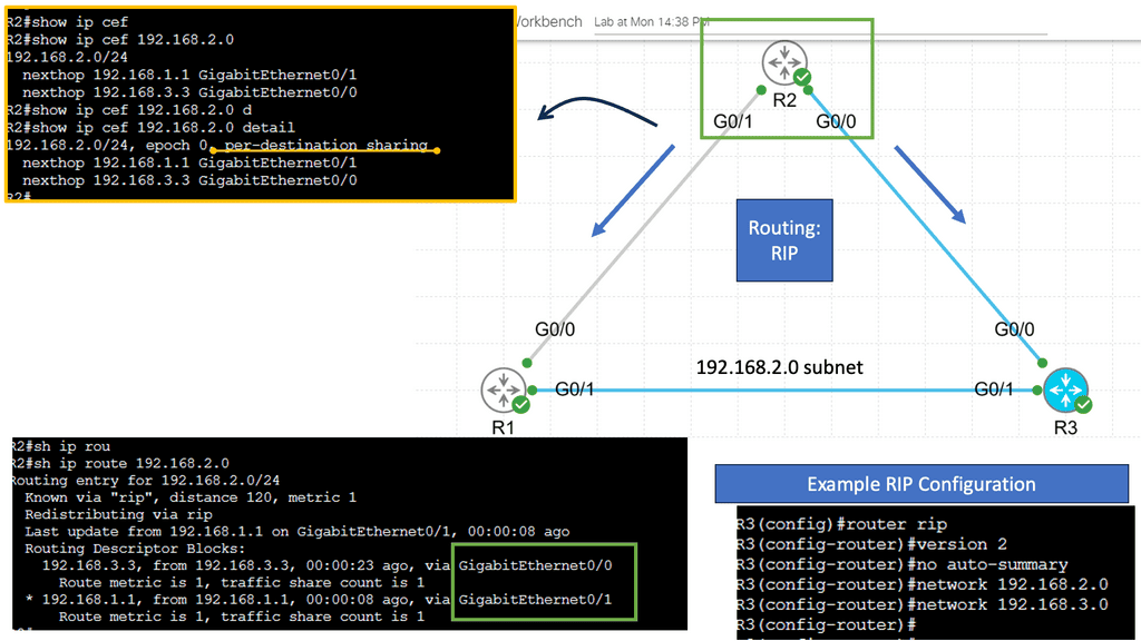
Example: Understanding RIP
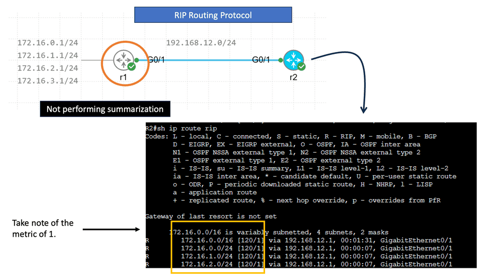
RIP, or Routing Information Protocol, is one of the oldest distance-vector routing protocols that is still in use today. Initially developed for smaller networks, RIP operates by sharing routing information between neighboring routers. It uses the hop count as its metric, representing the number of routers a packet must traverse to reach its destination.
RIP employs a simple approach to routing. Each router periodically broadcasts its routing table to its neighboring routers, which, in turn, update their tables accordingly. This process ensures that every router within the network has up-to-date knowledge of the available routes.
Example: OSPFv3
Understanding OSPFv3
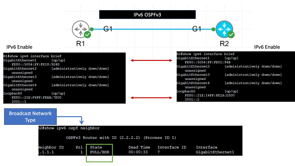
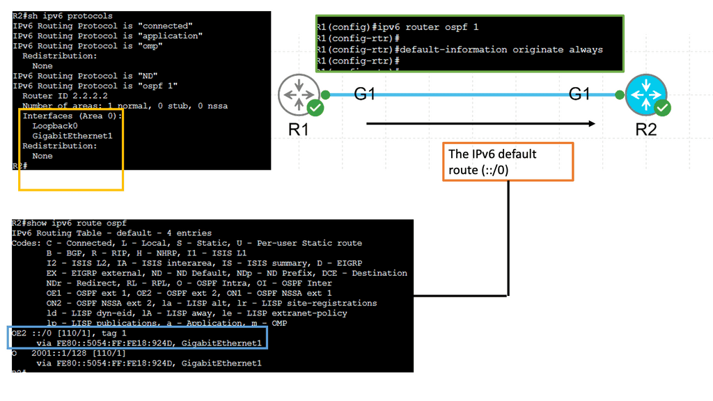
OSPFv3, which stands for Open Shortest Path First version 3, is an extension of OSPF tailored to support IPv6 networks. It operates on the same basic principles as OSPF, such as link-state advertisements and the shortest path first algorithm. However, OSPFv3 introduces several vital enhancements and modifications to accommodate IPv6 addressing and network infrastructure differences.
One of the significant changes in OSPFv3 is the handling of IPv6 addresses. Unlike OSPF for IPv4, OSPFv3 does not rely on network masks for route determination. Instead, It utilizes the IPv6 prefix length information embedded in each IPv6 address. This simplifies the routing process and ensures compatibility with IPv6’s expanded address space.
Starting points: Networking Protocols
Networking protocols facilitate communication between computer systems. Today, computer systems use three main protocols: Ethernet, TCP/IP, and Fibre Channel. Cables are used to connect various networking devices using Ethernet. Wireless computer networks are created using the TCP/IP protocol. Fiber channels are used to transfer large amounts of data between computers.
Routing, forwarding, and switching are network terms used when data is sent from one party to another. Each plays a crucial role in data delivery. Routing is the process of moving data from one device to another. Forwarding involves collecting data from one device and sending it to another. With switching, data is collected from one device and sent to multiple devices based on their MAC addresses.
Moving data between devices
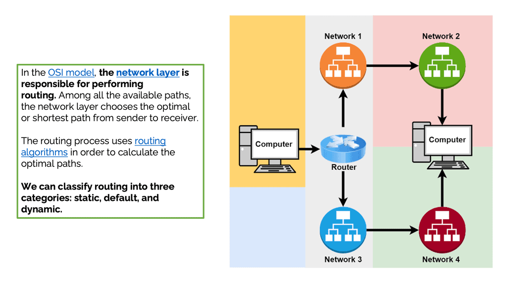
Moving data between devices is known as routing. Networking devices called routers perform routing most of the time. Furthermore, routers can forward connections to other networks. In addition, routers help create and manage networks. Within networks, they move data from one device to another. Routers can also transmit data across different networks in some cases. Routing is done at the network layer in the OSI model. The network layer chooses the optimal or shortest path from sender to receiver. Optimal paths are calculated using routing algorithms.
The forwarding process involves collecting data from one device and sending it to another. Unlike routing, this process does not move data between devices. Forwarding differs from routing because it performs some actions instead of simply forwarding packets. It doesn’t decide the path. The packets are only sent to another network in the forwarding process: The network layer performs routing and forwarding. Forwarding devices collect data and send it to another device. Switches, routers, and hubs are standard forwarding devices.
Forwarding Methods
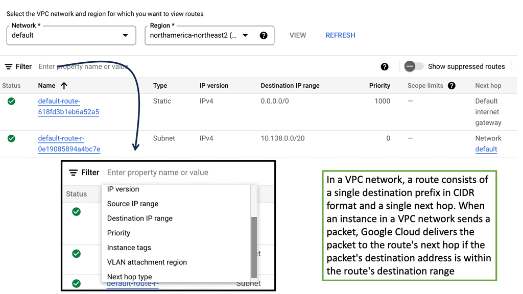
Let’s discuss some popular forwarding methods in networking. In the next hop method, packets are sent from the router to the next gateway in the direction of the destination. Routing tables with network-specific entries contain destinations connected to routers. A routing table is a set of rules, often displayed as a table, that determine where data packets will be directed over an Internet Protocol (IP) network. Routers and switches, as well as all IP-enabled devices, use routing tables. Lastly, when using the host-specific method, the routing table contains information about all the destination hosts in the destination network.
The Role of Switching
Data is switched from one port to another by collecting it from one port and sending it to the destination by switching. There are two types of switching: connectionless and connection-oriented. Connectionless switching does not require handshaking to establish a connection. A forwarding table determines how packets received in a port are sent. Conversely, connection-oriented switching uses a predefined circuit between the sender and receiver and an intermediate node ID.
Switching techniques can be divided into circuit, message, and packet switching. Circuit switching requires establishing a circuit before sending data. The received data is treated as a message when message switching is used and sent to the intermediate switching device. Packet switching breaks the data into small chunks called packets. Each packet is transmitted independently.
IP Routing
Routing is the process of moving IP packets from one network to another. IP routing protocols or static configuration allow routers to learn about nonattached networks. When a network topology change occurs, dynamic IP routing protocols update the network topology without intervention. Depending on the size of the network, IP routing may be limited to static routes due to design or hardware limitations.
Static routes are not accommodating when the topology changes and can be burdensome for network engineers. An IP packet is forwarded to its destination IP address with the help of a router that selects a loop-free path through a network.
Autonomous systems are networks of interconnected routers and related systems managed by a common network administrator. A global network of autonomous systems makes up the Internet.
Rules and Algorithms
Forwarding routing protocols are rules and algorithms determining the best path for data packets to follow within a network. They facilitate the exchange of routing information between routers and ensure that information is forwarded most efficiently. These protocols direct data packets from the source device to the correct destination device, providing reliable and timely delivery.
Example: EIGRP DUAL
DUAL, an abbreviation for Diffusing Update Algorithm, is the decision-making process EIGRP routers use to calculate the best path to reach a destination. It ensures loop-free and efficient routing within a network. To comprehend DUAL, we must explore its key components: the feasible distance (FD), reported distance (RD), and successor and feasible successor routes.
Feasible Distance (FD) is the metric for the best-known path to a destination. It represents the cumulative cost of all the links on that path. Reported Distance (RD) is the metric for a neighbor’s path to the same destination. These two values play a vital role in DUAL’s decision-making process. Successor routes are the best paths chosen by DUAL to reach a destination. A router selects the path with the lowest FD as its successor route.
Feasible Successor routes, on the other hand, are backup paths that have a higher FD but are still loop-free. These routes are pre-calculated and provide fast convergence if the successor route fails. Network convergence refers to the time it takes routers to update their routing tables after a change occurs in the network topology. DUAL plays a crucial role in achieving rapid convergence in EIGRP. DUAL minimizes the time and resources required for network convergence by maintaining successor and feasible successor routes.
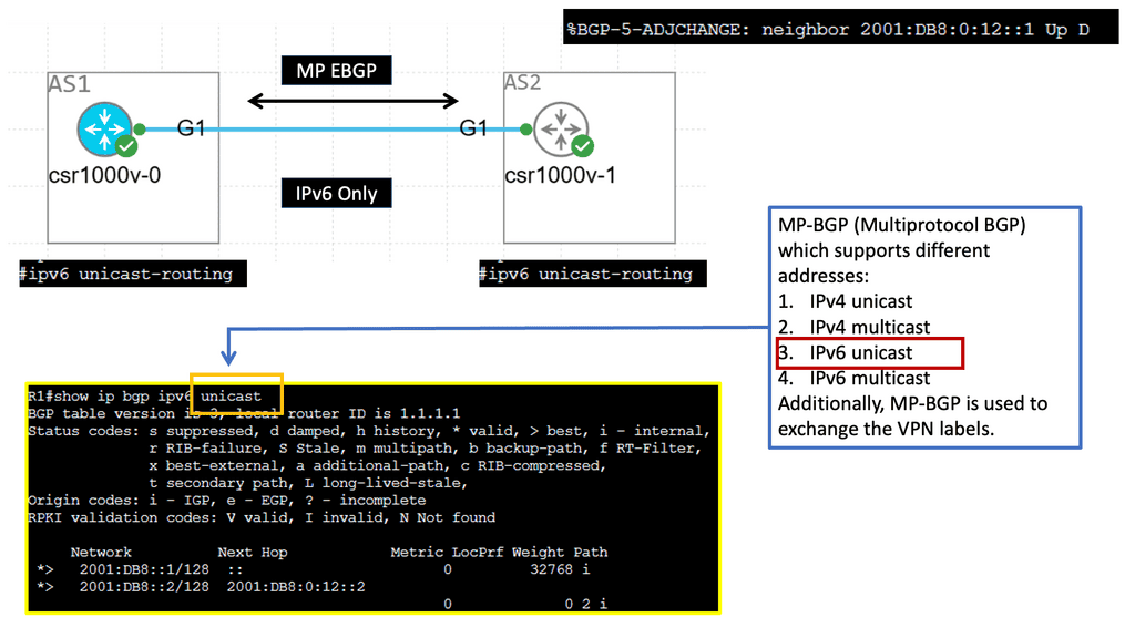
Example: MP-BGP with IPv6 Prefixes
Understanding MP-BGP
MP-BGP, or Multiprotocol Border Gateway Protocol, is a routing protocol that enables the exchange of routing information between networks. Unlike traditional BGP, which primarily deals with IPv4 routes, MP-BGP extends its capabilities to support multiple protocols, including IPv6. MP-BGP provides a flexible and scalable solution for modern network architectures by accommodating various protocols.
IPv6 adjacency refers to establishing connections between neighboring routers that utilize IPv6 addresses. With the depletion of available IPv4 addresses, IPv6 has become increasingly important in ensuring the continued growth and expansion of networks. MP-BGP plays a crucial role in enabling IPv6 adjacency by allowing routers to exchange routing information and establish connectivity efficiently and seamlessly.
**Common Forwarding Routing Protocols**
Two of the most commonly used forwarding routing protocols are Open Shortest Path First (OSPF) and Border Gateway Protocol (BGP). OSPF is an interior gateway protocol (IGP) used within autonomous systems and networks managed by a single administrative entity. It uses a link-state algorithm to determine the best route for data to travel. Conversely, BGP is an exterior gateway protocol (EGP) used to connect autonomous systems. It uses a path vector algorithm to determine the best route for data to travel.
Both protocols are essential for routing data across networks, and they both have their advantages and disadvantages. OSPF is more efficient and supports more features, while BGP is more secure and reliable. However, both protocols are required to communicate data across networks efficiently.
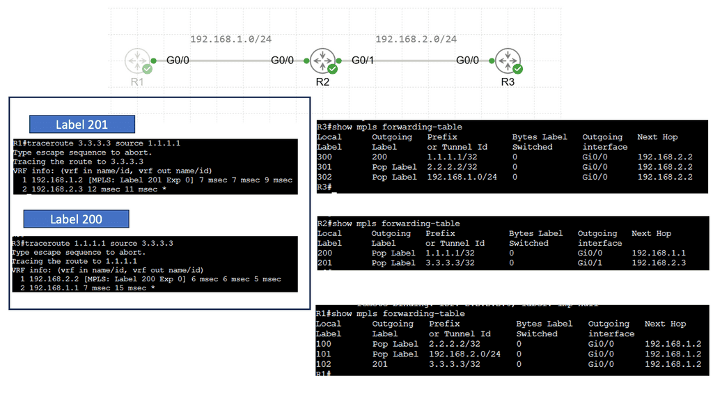
Understanding MPLS Forwarding
MPLS (Multiprotocol Label Switching) forwarding is a technique routers use to efficiently direct data packets through a network. Unlike traditional IP routing, MPLS forwarding employs labels to identify and forward packets along pre-determined paths quickly. By using labels, MPLS forwarding eliminates the need for complex IP lookups, resulting in faster and more streamlined data transmission.
Enhanced Performance: MPLS forwarding improves network performance by reducing latency and packet loss. Labels enable routers to make forwarding decisions more swiftly, resulting in lower transmission delays and increased overall efficiency.
Traffic Engineering: MPLS forwarding allows network administrators to engineer traffic paths based on specific requirements. By defining explicit paths for different types of traffic, MPLS enables better control over bandwidth utilization, ensuring that critical applications receive the necessary resources.
Quality of Service (QoS): MPLS forwarding enables the implementation of QoS policies, prioritizing certain types of traffic over others. This ensures that higher-priority applications, such as voice or video, receive the necessary bandwidth and experience minimal latency.
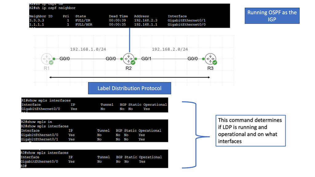
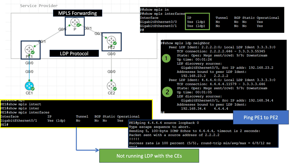
Understanding the Basics of LDP
LDP, or Label Distribution Protocol, is a signaling protocol that operates at the network layer. Its primary function is establishing and maintaining Label Switched Paths (LSPs) in a Multiprotocol Label Switching (MPLS) network. LDP enables routers to forward traffic along predetermined paths by assigning labels to network packets.
LDP Operation and Label Distribution
To comprehend LDP fully, it’s essential to understand how it operates and distributes labels. LDP uses a discovery mechanism to identify neighboring routers and establish peer relationships. Once peers are established, the protocol exchanges label mapping information, allowing routers to build forwarding tables and determine the appropriate paths for incoming packets.
Advanced Topic
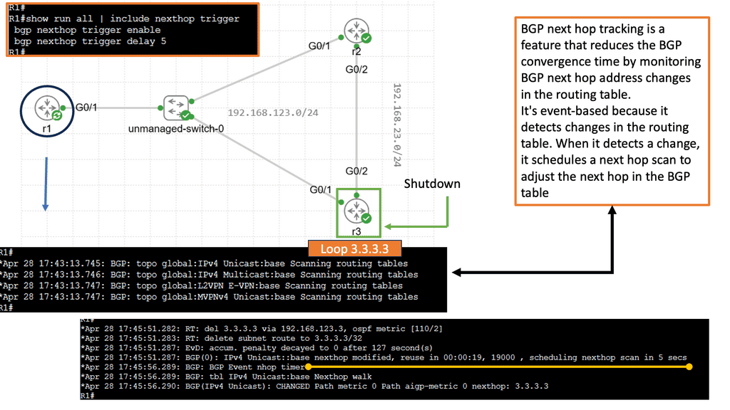
Understanding BGP Next Hop Tracking:
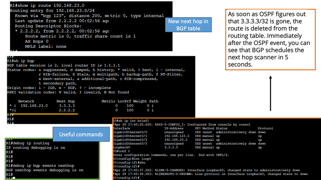
BGP Next Hop Tracking is a mechanism that allows a router to track the reachability of the next hop IP address in the routing table. Essentially, it enables routers to dynamically adjust their routing decisions based on the availability of the next hop. By monitoring the reachability of the next hop, BGP Next Hop Tracking enhances network stability and enables faster convergence during link failures or network changes.
Implementing BGP Next Hop Tracking requires proper configuration on BGP-enabled routers. The specific steps may vary depending on the network equipment and software being used. Generally, it involves enabling the Next Hop Tracking feature and specifying the desired parameters, such as the interval for tracking next hop reachability and the action to be taken upon reachability changes.
BGP Next Hop Tracking is useful in various network architectures. It is commonly used in multi-homed networks, where multiple ISPs are connected to a single network. By tracking the reachability of the next hops, routers can intelligently select the best path for sending traffic and avoid blackholing or suboptimal routing. Additionally, BGP Next Hop Tracking is beneficial when network policies require specific routing decisions based on next-hop reachability.
Understanding BGP Route Reflection
BGP route reflection is a technique to reduce the number of full-mesh peerings required in a BGP network. Network administrators can simplify their network topology and improve scalability by introducing route reflectors. Route reflectors act as centralized points for route distribution, allowing BGP speakers to establish fewer connections while still effectively exchanging routing information.
In a route reflection setup, route reflectors receive BGP updates from their clients and reflect those updates to other clients. The reflection process involves modifying the BGP attributes to preserve the path information while avoiding routing loops. This enables efficient propagation of routing information across the network while reducing the computational overhead associated with maintaining a full mesh of BGP peers.


Related: Before you proceed, you may find the following posts helpful:
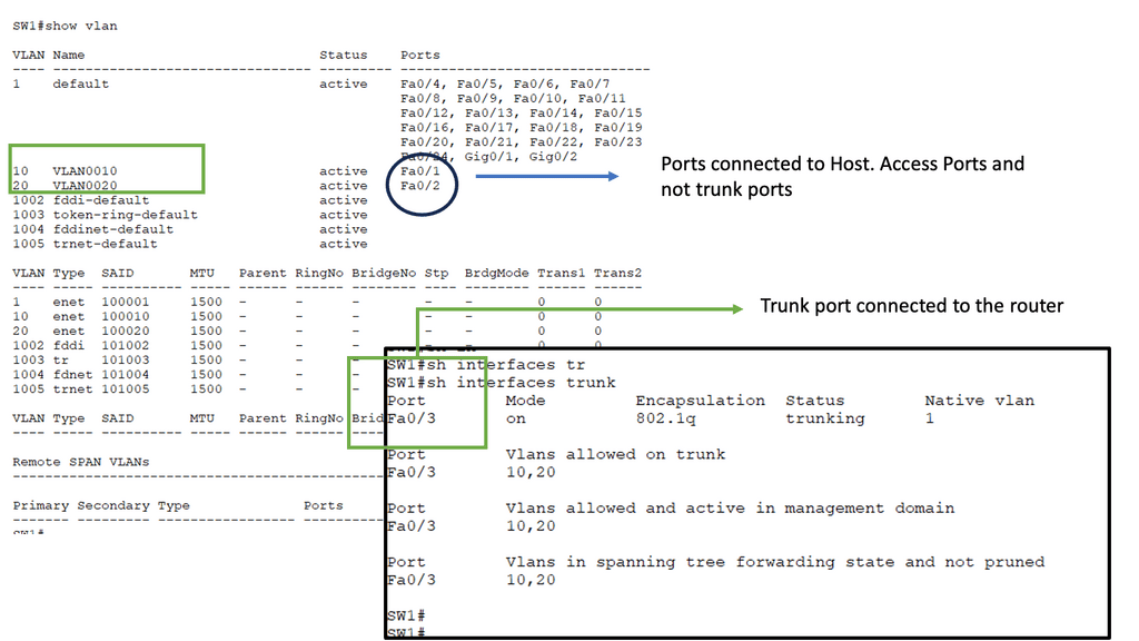
Switching and Routing
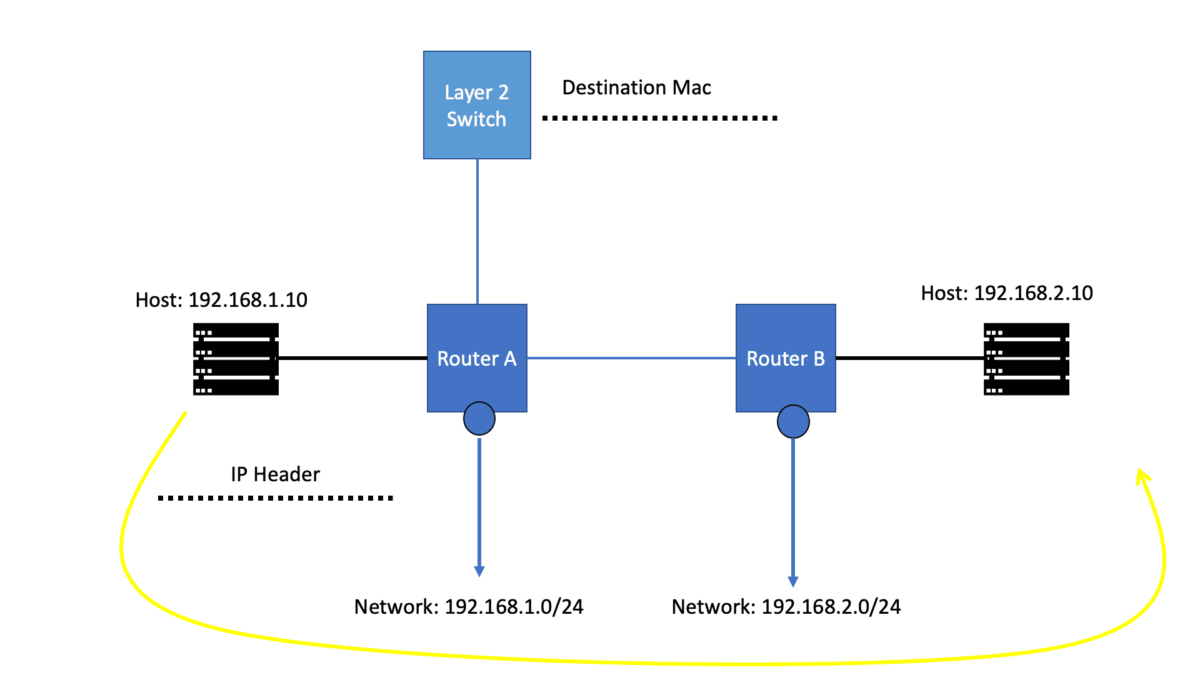
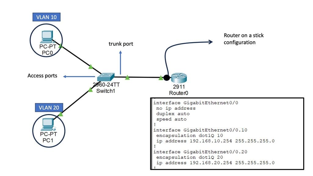
Before we get into the technical details of which protocol routers use to forward messages, let us address the basics. We know we have Layer 2 switches that create Ethernet LANs. So, all endpoints physically connect to a Layer 2 switch. And if you are on a single LAN with one large VLAN, you are prepared with this setup as switches work out of the box, causing conclusions based on Layer 2 MAC addresses. However, what if you want to send data from your network to another, across the Internet, or a different set of VLANs in different IP subnets?
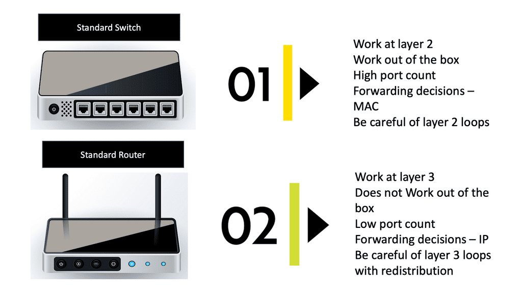
In this case, we need a Layer 3 router and an IP routing process with an IP forwarding algorithm. So, do you want to know which protocol routers forward messages? The Layer 3 router uses the information in the IP header to determine whether and where to forward each received packet and which network interface to send the packet to.
Examples: Forwarding Routing Protocols
- Routing Information Protocol (RIP)
One of the most commonly used forwarding routing protocols is the Routing Information Protocol (RIP). RIP is a distance-vector protocol that uses a metric, typically hop count, to determine the best path for data packets. It exchanges routing information with neighboring routers and updates its routing table accordingly. RIP is suitable for small to medium-sized networks due to its simplicity and ease of configuration.
- Open Shortest Path First (OSPF)
Another widely used forwarding routing protocol is the Open Shortest Path First (OSPF) protocol. OSPF is a link-state protocol that calculates the shortest path to a destination based on various factors, such as bandwidth, delay, reliability, and cost. It advertises link-state information to neighboring routers, allowing them to build a complete network topology. OSPF is commonly implemented in large-scale networks due to its scalability and advanced features.
- Border Gateway Protocol (BGP)
Border Gateway Protocol (BGP) is a forwarding routing protocol commonly used in internet service provider (ISP) networks. BGP is an exterior gateway protocol that facilitates the exchange of routing information between different autonomous systems (ASes). It enables ISPs to select the best path for data packets based on various policies, such as path length, network congestion, and customer preferences. BGP is crucial for maintaining a stable and efficient internet routing infrastructure.
Guide: OSPF
In the following lab guide, we address OSPF. OSPF, developed by the Internet Engineering Task Force (IETF), is an interior gateway protocol (IGP) used for routing within autonomous systems (AS). A link-state routing protocol uses the Shortest Path First (SPF) algorithm to determine the best path for forwarding data packets. OSPF is widely adopted due to its scalability, fast convergence, and support for multiple network types.
Note:
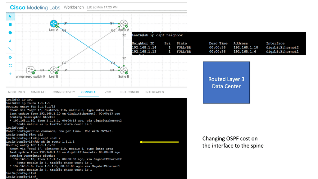
Notice that we have two OSPF neighbors. We use the default broadcast network type and have an OSPF status of FULL/DR. I have changed the OSPF cost on the link Gi1 so that we can perform traffic engineering. Now that the links have the exact OSPF costs, a total metric of 4, we can perform ECMP. You can also bond links; we combine two links for additional bandwidth.
Example: OSPF Routed Core
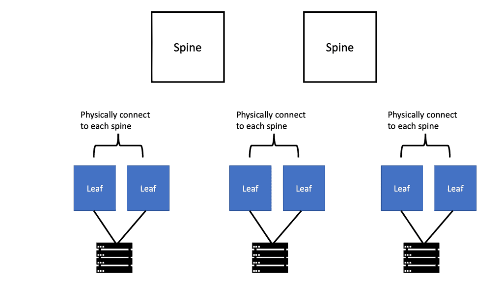
With a leaf and spine, we can have a routed core. So, we gain the benefits of running a routing protocol, such as OSPF, all the way down to the access layer. This has many advantages, such as full use of links. The guide below has three routers: two leaves and two spines. OSPF is the routing protocol with Area 0; we are not running STP.
Therefore, we can have Layer 3 routing for both spines to reach the destinations on Leaf B. I have a loopback configured on Leaf B of 1.1.1.1. Each leaf has an OSPF neighbor relationship to each spine with an OSPF network type of Broadcast. Notice the command: Show IP route 1.1.1.1 on Leaf A.
Note:
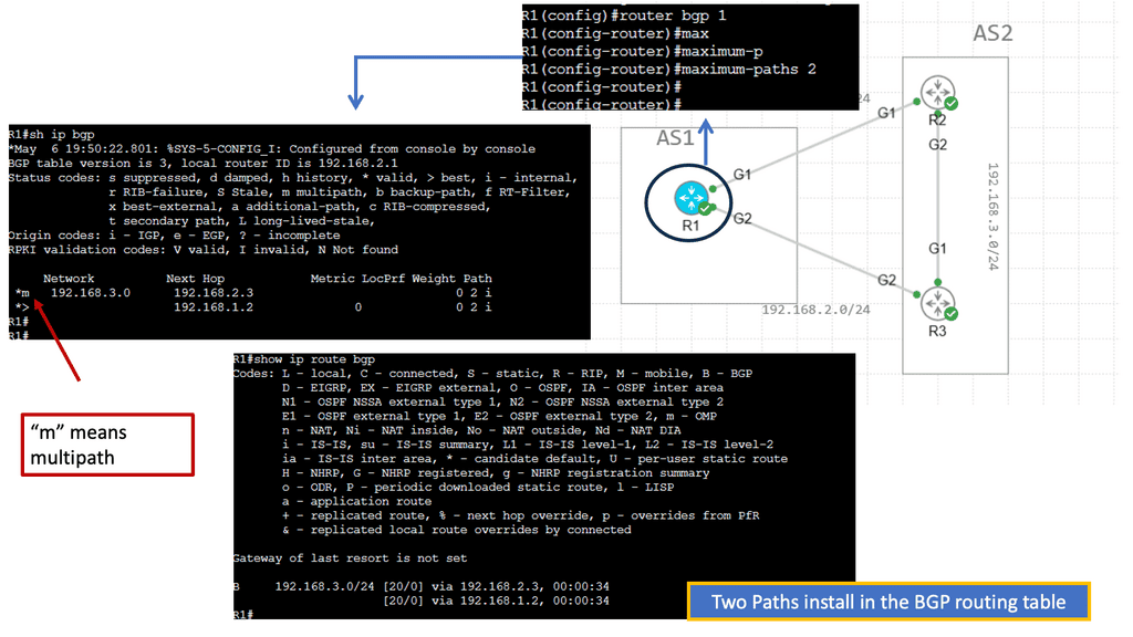
We initially only had one path via Spine B, i.e., the shortest path based on OSPF cost. Once I made the OSPF costs the same for the entire path (Cost of 4, routing metric of 4 ), we installed 2 paths in the routing table and can now rely on the fast convergence of OSPF for link failure detection and recovery.
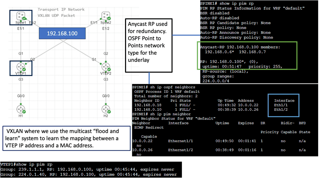
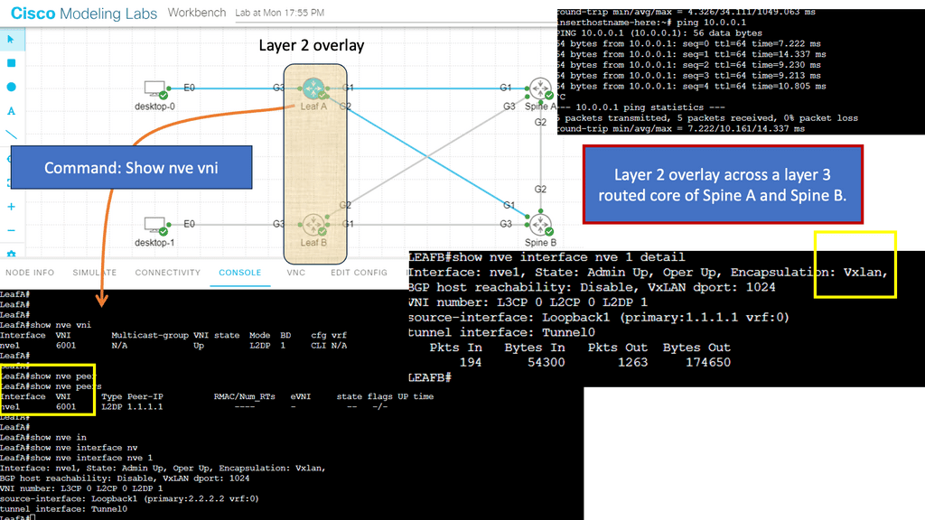
We will expand this with one of the following lab guides in this blog with VXLAN and create a layer 2 overlay. Remember that ACI does not have OSPF and uses IS-IS; it also has a particular configuration for VXLAN, and much of the CLI complexity is abstracted. However, the focus of these lab guides is on illustration and learning.
The process of routing and network stretch
Routing is selecting a path for traffic in a network or between or among multiple networks. Routing is performed for various networks, including the Internet, circuit-switched, and packet-switched networks. The routing process usually directs forwarding based on routing tables, which maintain a record of the routes to various network destinations. Thus, constructing routing tables in the router’s memory is crucial for efficient routing.
Routing is typically based on the shortest path algorithm, which finds the shortest path from source to destination in a network. The shortest path algorithm can be implemented using various techniques, such as Dijkstra’s and Bellman-Ford’s algorithms. In addition, routing can also be based on other criteria, such as least cost, lowest delay, or highest reliability.
Routing Tables:
Routing protocols are used to maintain router routing tables. These protocols enable the routers to exchange information about the network topology, such as which nodes are connected, and then determine the best routes. The most common routing protocols are the Open Shortest Path First (OSPF) and the Routing Information Protocol (RIP).
Routing also ensures that data sent over the Internet reaches its destination. To do this, routers use the Internet Protocol (IP) to forward packets between networks. They examine the packet’s IP header and use this information to determine the best route for the packet.
Guide: EIGRP Configuration
EIGRP stands for Enhanced Interior Gateway Routing Protocol and is a routing protocol created by Cisco. Initially, it was only available on Cisco hardware, but for a few years, it’s now an open standard. EIGRP is called a hybrid or advanced distance vector protocol, and most of the rules that apply to RIP also apply here:
- Split Horizon
- Route Poisoning
- Poison Reverse
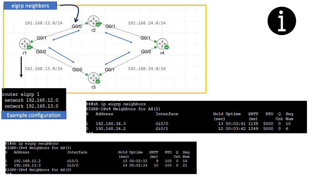
EIGRP routers will send hello packets to other routers like OSPF; if you send and receive them, you will become neighbors. EIGRP neighbors will exchange routing information, which will be saved in the topology table
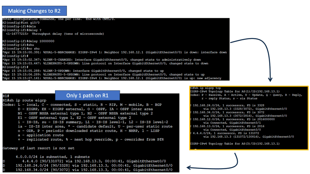
Configuring EIGRP is similar to RIP. The “1” is the AS number, which must be the same on all routers! We require the no auto-summary command because, by default, EIGRP behaves classfully, and we want it to be classless.
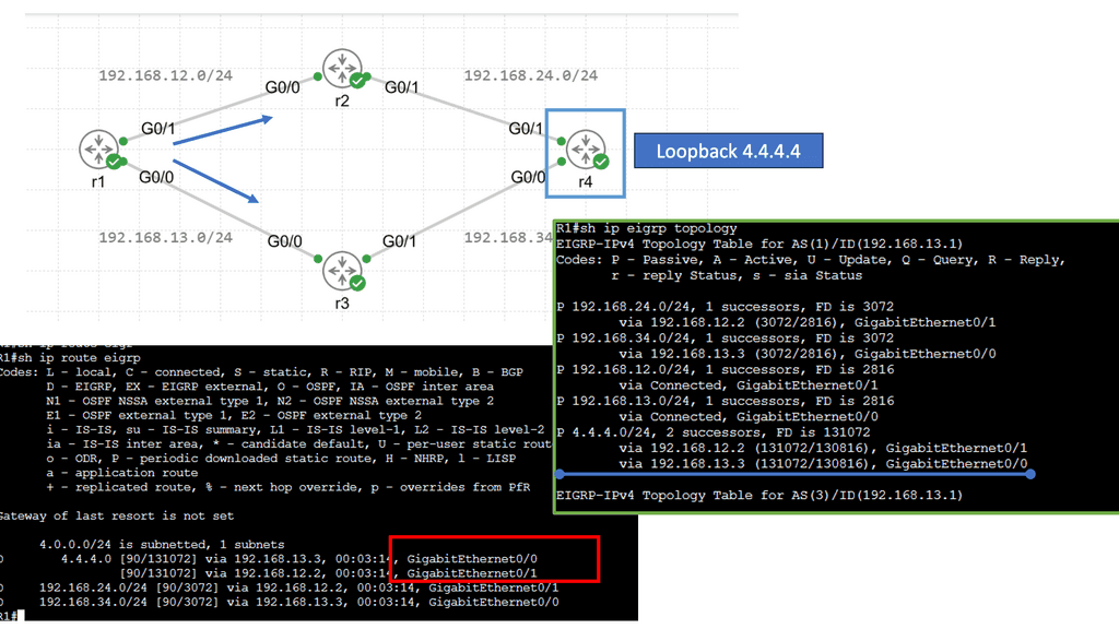
Next, let’s have a look at the routing table below. The first thing you might notice is that you see a “D” for the EIGRP entries. You see a “D” and not an “E” because the last one has already been taken for EGP, an old routing protocol we no longer use. “D” stands for “dual,” which is the mechanism behind EIGRP. The loopback 4.4.4.0 is connected to R4, and R1 has two ways to reach this network. This is because all links are Gigabit Ethernet, and I have not changed any metrics.
Routing vs Forwarding
Often, routing is confused with forwarding, but routing is a different process. When routing data, routers move data between devices. During data forwarding, a device collects data from one device and sends it to another. Let’s take a closer look at the forwarding process.
The forwarding process involves collecting data from one device and sending it to another. Data is not moved from one device to another in this process. In contrast to routing, forwarding performs some actions and forwards packets to intermediate routers. It does not determine the path. We only forward the packets to another attached network in the forwarding process.
The network layer performs both routing and forwarding. A forwarding device collects data and sends it to another. Hubs, routers, and switches are some of the most popular forwarding devices.
Guide: IS-IS Routing Protocol
In the following sample, we have an IS-IS network.
The ISIS routing protocol is a link-state routing protocol that operates at the OSI (Open Systems Interconnection) layer 2. It was initially developed for large-scale networks such as the Internet, where scalability, stability, and efficient routing are paramount.
Note:
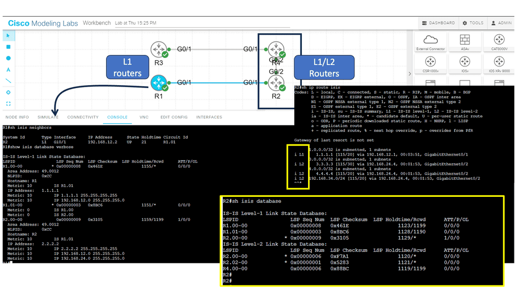
Below, we have four routers. R1 and R2 are in area 12, and R3 and R4 are in area 34. R1 and R3 are intra-area routers so they will be configured as level 1 routers. R2 and R4 form the backbone so these routers will be configured as levels 1-2.
**Key Features of ISIS Routing Protocol**
Hierarchical Design: ISIS employs a hierarchical design, dividing the network into areas to simplify routing and improve scalability. Each region has a designated router, the Intermediate System (IS), which is responsible for exchanging routing information with other ISes.
Link-State Database: ISIS maintains a link-state database that contains information about the network topology and the state of individual links. This database calculates the shortest path to a destination and ensures efficient routing.
Dynamic Updates: ISIS uses a dynamic routing algorithm to exchange routing information between ISes. It continuously updates the link-state database based on network changes, ensuring the routing information is always current.
Support for Multiple Routing Protocols: ISIS is interoperable with protocols such as OSPF (Open Shortest Path First) and BGP (Border Gateway Protocol). This flexibility allows networks to integrate ISIS with existing routing infrastructures seamlessly.
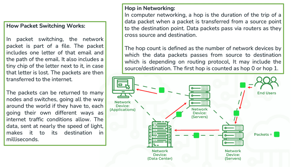
Packet-switching Networks
The Internet is a packet-switching network that enables its attached devices, such as your personal computer ( PC ), to exchange information with other devices. Information exchange could take many different forms. From a user level, it could be checking your bank balance with Internet banking, buying a book on an Amazon website, watching a movie online, or downloading your favorite song.
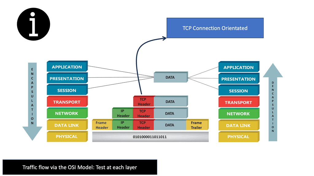
Hypertext Transfer Protocol ( HTTP ) accounts for most Internet traffic and is the protocol behind the World Wide Web ( WWW ). However, for these upper-layer protocols ( HTTP ) to work efficiently and offer a satisfactory user experience, elements lower in the Open Systems Interconnection ( OSI ) communication module must be fine-tuned and operational for data transfers.
Forwarding Protocols
Which protocol is used by routers to forward messages?
- The two transport protocols
The TCP/IP protocol suite supports two transport protocols ( Layer 4 ): Transmission Control Protocol (TCP ) and User Datagram Protocol ( UDP ). TCP reliably provides a host-to-host communication service, while UDP provides host-to-host communication in an unreliable fashion.
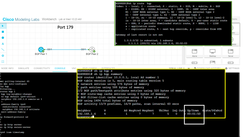
As a result, TCP offers many services better suited for applications requiring certain service guarantees and error correction and detection, such as Border Gateway Protocol, which operates on Port 179. On the other hand, UDP offers fewer services and is helpful for situations where packet loss is less sensitive, but time delays are more problematic.
This information is traversed across the Internet backbone via the Network ( Layer 3 ) and Data Link layer ( Layer 2 ). It is encoded in long strings of bits called packets. Packets describe a chunk of data going from the IP ( Internet Protocol ) layer to the network interface ( Data Link Layer ).
Guide: BGP Next hop tracking
BGP Next Hop Tracking is a feature within the BGP routing protocol that allows routers to track the reachability of next-hop IP addresses. By monitoring the availability of next-hop routers, network administrators can make informed decisions regarding traffic routing and ensure efficient packet transmission.
BGP Next Hop Tracking offers several advantages in terms of network resilience. Firstly, it enables the identification and avoidance of black holes or suboptimal routing paths by detecting unreachable next-hop IP addresses. This ensures traffic is efficiently routed along viable paths, minimizing latency and potential packet loss. Additionally, BGP Next Hop Tracking facilitates faster convergence during network failures by swiftly redirecting traffic to alternate paths, reducing the impact of network disruptions.
The Packet and a Datagram
A packet is not the same as a datagram and can be either an IP datagram or a fragment of an IP datagram. Note: The terminology “packet” refers to the Ethernet payload, which consists of the IP header and the user data. The terminology frame refers to the data link headers and the payload.
As these packets travel through the Internet from their source ( your personal computer ) to their destination ( Amazon website ), certain decisions are made by each device the packet traverses. These are known as routing decisions and determine if the packet should go this way or that way.
The devices making these decisions are called routers. Different routers act at different network points, such as over the WAN with SD-WAN routers: SD WAN tutorial.
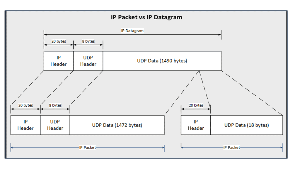
IP Packet versus IP Datagram
The diagram shows the different definitions of an IP packet compared to an IP datagram. It also shows how an IP datagram is fragmented into two IP packets, with the second IP packet being the second part of the first IP packet.
Routing Tables and Routing Protocols
These devices have a routing table that tells them how and where to forward the packets. The routing table is populated by a dynamic or static process called a routing protocol. A static routing protocol is specific to that device, manually configured, and is not automatically populated to other routers.
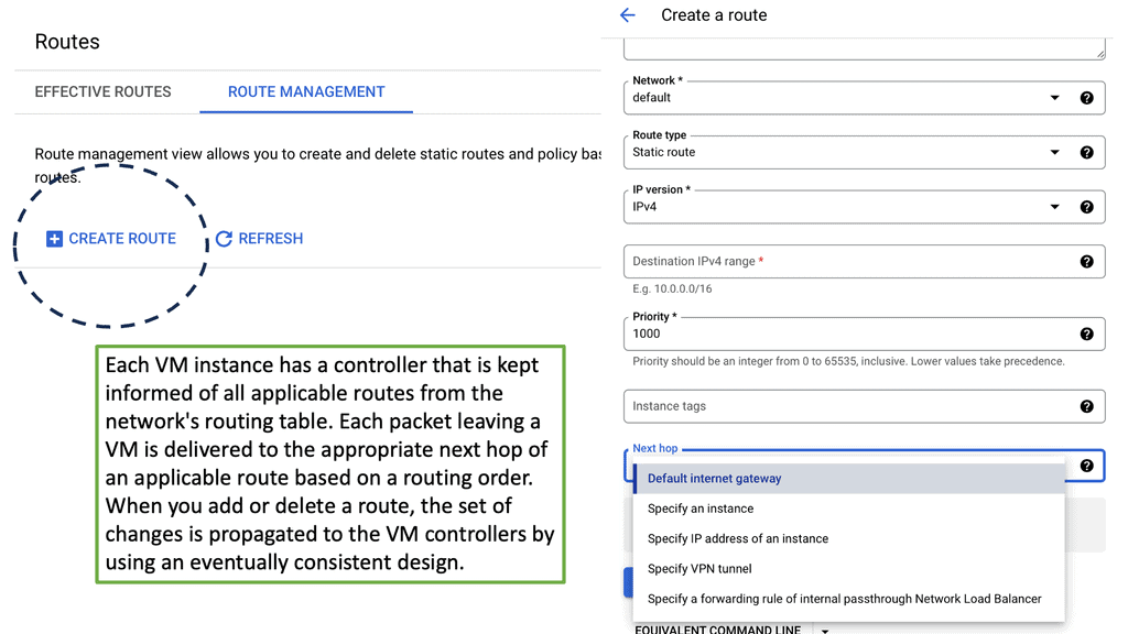
A dynamic process runs distributed algorithms that the routers run among themselves to make the correct routing decision.
An example of a dynamic routing protocol is OSPF, and a static routing protocol would be a static route. A router’s routing protocol may be Distance Vector Algorithms or Link-State Algorithms. Distance Vector Algorithms are more straightforward and usually try to find paths with a simple metric, such as the number of router hops ( devices ) to the destination.
On the WAN side, we have Border Gateway Protocol (BGP) and the use case of BGP SDN. We are enabling WAN virtualization and SDN traffic optimizations.
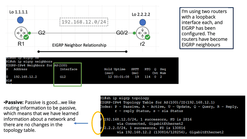
Guide: EIGRP
In the following, we have an EIGRP network that consists of two routers.
Note:
Efficient Exchange of Routing Information
One of EIGRP’s strengths is its ability to exchange routing information with neighboring routers. Using Hello packets and Update packets, EIGRP establishes and maintains neighbor relationships. This dynamic exchange ensures that routers are constantly updated with the latest network topology information, facilitating efficient route computation and decision-making.
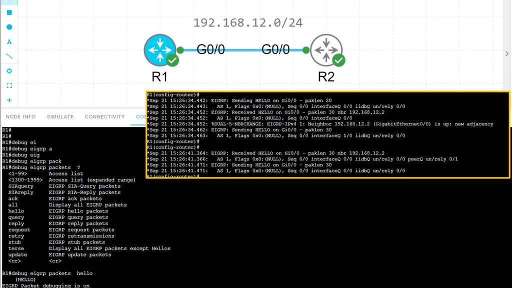
For neighbor discovery and recovery, EIGRP neighbors send hello packets. If you send and receive hello packets, EIGRP will form a neighbor relationship with another router. If you receive hello packets from the other side, EIGRP will assume the other router is still present. When you no longer receive them, you’ll lose the neighbor relationship called adjacency, and EIGRP might have to look for another route.
EIGRP uses RTP (Reliable Transport Protocol) to deliver packets between neighbors in a reliable and orderly manner. There are two ways to send packets, multicast and unicast, and not all packets are sent reliably to keep things efficient. We need acknowledgment from the other side to ensure our packets are reliable.
Analysis:
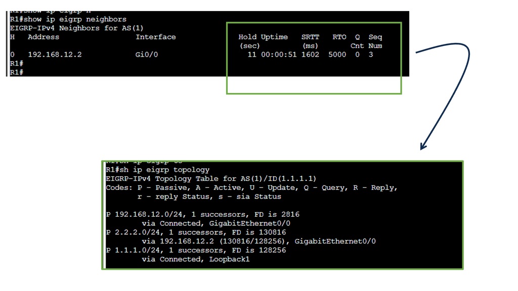
Populating the Topology Table
EIGRP populates its topology table by exchanging Hello and Update packets with neighboring routers. These packets carry information about the network’s topology, such as feasible successors, advertised distances, and reported distances. As EIGRP receives these updates, its topology table will be updated accordingly.
- Computing the Best Paths
Once the topology table is populated, EIGRP utilizes the DUAL algorithm to determine the best paths to reach destination networks. The algorithm considers bandwidth, delay, reliability, and load to calculate each route’s composite metric, the metric value. This metric value aids in selecting the optimal path for packet forwarding.
- Maintaining and Updating the Topology Table
The EIGRP topology table is a dynamic entity that undergoes constant updates. EIGRP ensures that the topology table is kept current as changes occur in the network. When a link or router fails, EIGRP recalculates paths based on the remaining available routes and updates the topology table accordingly.
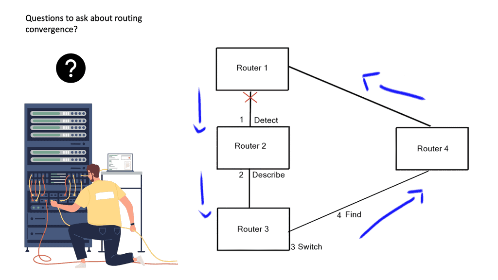
- Routing convergence: Determine the Best Path
A router runs its algorithm and determines the best path to a particular destination; the router then notifies all of the neighboring routers of its current path; concurrently, the router’s neighbors also inform the router of their best paths. All of this occurs in a process known as routing convergence.
Rouitng Convergence | Forwarding in Networking |
After seeing all the other best paths from its neighboring devices, the router may notice a better path through one of its neighbors. If so, the router updates its routing table with better paths. A link-state algorithm employs a replicated database approach compared to a Distance Vector Algorithm ( distributed calculation ).
Each router contributes to database pieces; every device adds an element to create a complete network map. However, instead of advertising a list of distances to each known destination, the router advertises the states of its local links ( interfaces ).
- Link state advertisements
These link-state advertisements are then advertised to the other routers; all these messages combine to complete a network database synchronized between each router at regular intervals.
Essentially, link-state protocols must flood information about the topology to every device in the network, and the distance ( path ) vector protocols must process the topology change information at every hop through the network.
A final note on forwarding protocols: Forwarding routing protocols
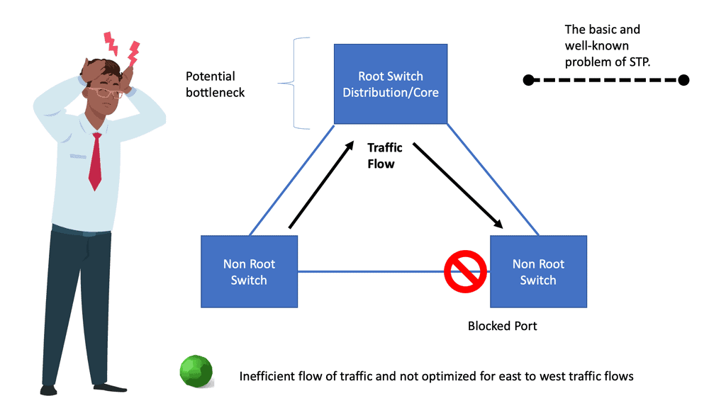
Routing protocols continually reevaluate their contents, and the process of finding new information after a change in the network is called convergence. A network deemed to be highly available must have not only a redundant physical topology but also fast convergence so that service degradation or interruption is avoided. Convergence should be designed efficiently at Layer 2 and Layer 3 levels.
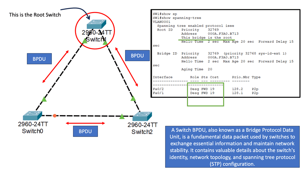
Fast convergence of Layer 2 environments is designed with the Spanning Tree Protocol ( STP ) enhancements, notably PVST+. In L3 environments, we prefer routing protocols that can quickly find new information ( next hops ), with protocols having a short convergence.
You might conclude from the descriptions of both link-state and distance-vector protocols that link-state algorithms will always converge more quickly than distance or path-vector protocols. However, this isn’t the case; both converge exceptionally promptly if the underlying network has been designed and optimized for operation.
Closing Points: Forwarding Routing Protocols
Forwarding routing protocols play a crucial role in efficiently transmitting data across networks. This blog post delved into forwarding routing protocols, exploring their significance, functionality, and types. By the end, you will clearly understand how these protocols enable seamless communication between devices on a network.
Forwarding routing protocols have several key benefits that make them essential in network communication:
1. Scalability: Forwarding routing protocols enable networks to expand and accommodate a growing number of devices. These protocols dynamically adapt to changes in network topology, allowing for the seamless integration of new devices and routes.
2. Redundancy: Forwarding routing protocols continuously exchange routing information to ensure alternative paths are available in case of link failures. This redundancy enhances network reliability and minimizes downtime.
3. Load Balancing: Forwarding routing protocols distribute network traffic across multiple paths, optimizing network performance and preventing congestion. This feature allows for efficient utilization of network resources.
Types of Forwarding Routing Protocols:
Various forwarding routing protocols are designed to cater to specific network requirements. Let’s explore some of the most commonly used types:
1. Distance Vector Protocols:
Distance vector protocols, such as the Routing Information Protocol (RIP), use a simple approach to determining the best path. Routers exchange their routing tables, which contain information about the distance and direction of various network destinations. RIP, for example, evaluates paths using hop count as a metric.
2. Link State Protocols:
Link state protocols, such as Open Shortest Path First (OSPF), build a detailed database of the network’s topology. Routers share information about their directly connected links, allowing each router to construct a complete network view. This comprehensive knowledge enables OSPF to calculate the shortest path to each destination.
3. Hybrid Protocols:
Hybrid protocols, like Enhanced Interior Gateway Routing Protocol (EIGRP), combine elements of both distance vector and link state protocols. These protocols balance simplicity and efficiency, utilizing fast convergence and load-balancing features to optimize network performance.
Forwarding routing protocols are essential for ensuring reliable and efficient data transmission in computer networks. By determining the optimal paths for data packets, these protocols contribute to the overall performance and stability of the network. Understanding different forwarding routing protocols, such as RIP, OSPF, and BGP, is crucial for network administrators and engineers to design and manage robust networks.
Forwarding protocols are vital in modern networking, enabling efficient data routing and seamless network communication. Understanding these protocols’ different types, benefits, and challenges is crucial for network administrators and engineers. Organizations can confidently navigate the digital highway by implementing best practices and staying abreast of advancements in forwarding routing protocols.