Understanding Application Traffic Steering:
A: ) Application traffic steering refers to the strategic routing and distribution of network traffic to different applications or services within a network infrastructure. It involves directing traffic flows based on various factors, such as performance, availability, security, and user-defined policies. This dynamic process optimizes resource utilization and helps deliver an exceptional user experience.
B: ) Application traffic steering, traffic management, or load balancing intelligently distributes network traffic to multiple servers or resources to enhance efficiency and availability. By dynamically redirecting traffic based on predefined rules or algorithms, organizations can ensure seamless user experiences and prevent the overloading of specific servers. A network engineer manipulates your network to suit your traffic.
C: ) Steering policies can be configured for individual applications based on the application name, category, signature, URL, and domain. After classifying traffic, it can be directed along the available paths. The Application Steering strategy provides finer granularity for routing traffic than traditional destination-based routing. Furthermore, multiple applications can be steered from the same port and destination with Application Steering.
-Enhanced Performance: By efficiently distributing network traffic, application traffic steering optimizes resource usage, reduces response times, and improves application performance. Users experience faster loading times, lower latency, and seamless interactions with the application.
-Improved Scalability: Application traffic steering facilitates horizontal scaling, allowing organizations to handle increased traffic loads without sacrificing performance. Organizations can scale their resources by intelligently distributing traffic across multiple servers, ensuring smooth operations during peak usage.
High Availability: Application traffic steering allows organizations to achieve high availability by intelligently routing traffic away from overloaded or malfunctioning servers. By seamlessly redirecting traffic to healthy servers, organizations can minimize downtime and ensure uninterrupted application access.
Traffic Engineering Considerations:
**Key Technologies Enabling Traffic Steering**
Several technologies underpin the effectiveness of application traffic steering. Software-Defined Networking (SDN) and Network Functions Virtualization (NFV) are at the forefront, providing the flexibility and scalability needed to manage complex networks. SDN separates the control plane from the data plane, allowing for centralized network management, while NFV enables the virtualization of network services. Together, these technologies facilitate the dynamic adjustment of traffic paths, ensuring optimal performance and reliability.
**Benefits of Effective Traffic Steering**
The benefits of implementing robust traffic steering mechanisms are vast. Firstly, it enhances the performance of applications by reducing latency and improving response times. Secondly, it increases network reliability by automatically rerouting traffic in case of path failures or congestion. Additionally, traffic steering can enhance security by directing data through secure paths and preventing unauthorized access. For businesses, this translates into improved customer satisfaction, reduced operational costs, and a competitive edge in the market.
**Challenges and Considerations**
Despite its advantages, implementing application traffic steering comes with its own set of challenges. One major concern is the complexity of integrating traffic steering solutions into existing network infrastructures. It requires careful planning and a thorough understanding of network dynamics. Furthermore, businesses must consider the cost implications and ensure they have the necessary technical expertise to manage and maintain these systems. Addressing these challenges is crucial for reaping the full benefits of traffic steering.
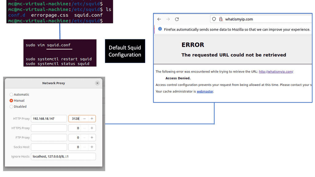
Understanding Squid Proxy
Squid Proxy, an open-source caching and forwarding HTTP web proxy, acts as an intermediary between clients and servers. It enhances performance by caching frequently accessed web content, reducing bandwidth usage, and improving response times. Its versatility and extensive features make it a popular choice for individuals and organizations alike.
1. Enhanced Speed and Performance:
By caching frequently accessed web content, Squid Proxy significantly reduces the load on servers, resulting in faster response times and improved overall browsing speed.
2. Bandwidth Optimization:
Squid Proxy optimizes bandwidth usage by compressing data, filtering out unwanted content, and implementing advanced caching algorithms. This leads to a more efficient utilization of available bandwidth resources.
3. Content Filtering and Security:
One of the notable features of Squid Proxy is its ability to filter web content based on predefined rules. This empowers network administrators to control access tospecific websites, block malicious content, and ensure a safer browsing environment.

Techniques for Application Traffic Steering
Load Balancing: Load balancing is a foundational technique in application traffic steering. It involves distributing incoming network traffic across multiple servers, ensuring optimal resource utilization, and preventing bottlenecks. Load balancing can be achieved through various methods, such as round-robin, least connections, or weighted distribution, depending on the specific needs of the network infrastructure.
Content-based Routing: Content-based routing directs traffic based on specific criteria within the application payload. This technique enables intelligent decision-making by examining the content of incoming requests and routing them to appropriate servers or resources. By leveraging factors such as URL, headers, or session information, content-based routing ensures efficient handling of diverse application traffic.
Geographic Traffic Steering: Geographic traffic steering focuses on redirecting network traffic based on geographic location. By considering factors such as user proximity, latency, or data center availability, organizations can route traffic to the nearest or most suitable servers. This technique minimizes latency, improves response times, and enhances overall user experience.
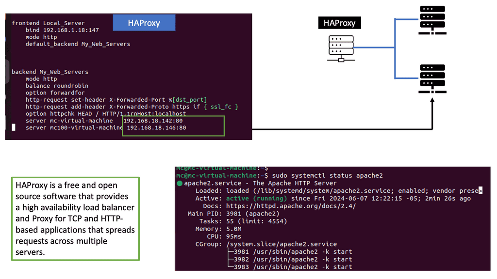
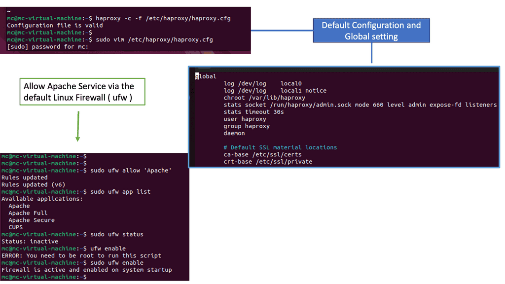
Example: Load Balancing with HAProxy
Understanding HAProxy
HAProxy, which stands for High Availability Proxy, is an open-source load balancer and proxy server. It acts as an intermediary between client requests and backend servers, distributing traffic and optimizing resource utilization. Its lightweight and high-performance nature make it a top choice for many organizations.
HAProxy offers a plethora of features that contribute to its effectiveness in web traffic management. From load balancing algorithms, SSL termination, to health checks and session persistence, HAProxy provides comprehensive solutions to handle diverse traffic scenarios. Its scalability, flexibility, and robustness make it an ideal choice for businesses of all sizes.
One of the notable advantages of HAProxy is its extensive configuration options. Administrators can fine-tune and customize various aspects of traffic management, including routing rules, request and response manipulation, and logging. The flexibility to adapt HAProxy to specific requirements empowers organizations to optimize their web infrastructure efficiently.
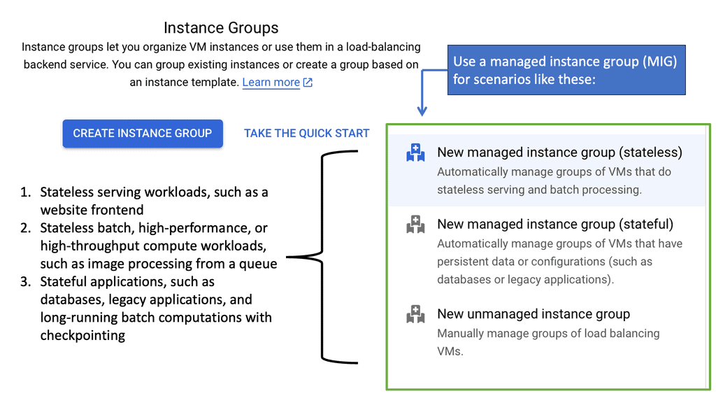
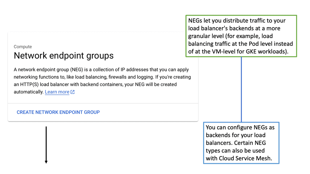
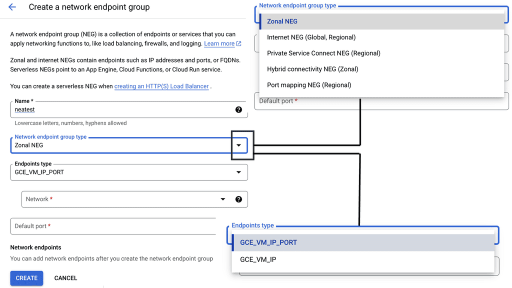
Google Cloud NEGs
**Understanding the Role of Network Endpoint Groups**
Network Endpoint Groups serve as a collection of endpoints that facilitate the distribution and management of network traffic. They come in handy when dealing with applications that require precise traffic steering across distributed environments. In the context of Google Cloud, NEGs can include both VM instances and non-VM endpoints, enabling a versatile approach to traffic management. By defining specific endpoints within a NEG, businesses can ensure that their applications are responsive and resilient, even under varying network conditions.
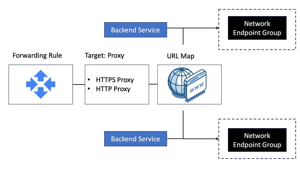
**Application Traffic Steering with Google Cloud**
One of the primary advantages of Network Endpoint Groups is their ability to steer application traffic effectively. Google Cloud provides a robust set of tools to configure and manage NEGs, allowing businesses to dynamically route traffic based on predefined policies. This capability is particularly beneficial for applications that require low latency and high availability. By leveraging NEGs, organizations can direct traffic to the nearest or most responsive endpoints, optimizing user experience and resource utilization.
**Implementing NEGs for Enhanced Scalability**
Scalability is a critical consideration for any business operating in the digital landscape. Network Endpoint Groups offer an efficient way to scale applications by distributing traffic across multiple endpoints. This distribution not only enhances performance but also provides a level of redundancy that can protect against endpoint failures. With Google Cloud’s integrated tools, businesses can easily adjust their network architecture to accommodate increased demand, ensuring that their applications remain available and performant.
**Best Practices for Managing Network Endpoint Groups**
To maximize the benefits of Network Endpoint Groups, it’s important to adhere to best practices in their implementation and management. Start by clearly defining your traffic management goals and configuring NEGs to align with these objectives. Regularly monitor traffic patterns and adjust endpoint configurations as needed to maintain optimal performance. Additionally, take advantage of Google Cloud’s load balancing and health-checking features to ensure that traffic is always directed to healthy endpoints.
Understanding Load Balancing in Google Cloud
Load balancing in GCP is a fundamental concept that allows applications to scale, handle increased traffic, and ensure seamless user experiences. Google Cloud offers two primary types of load balancers: Network Load Balancer and HTTP Load Balancer. Let’s take a closer look at each.
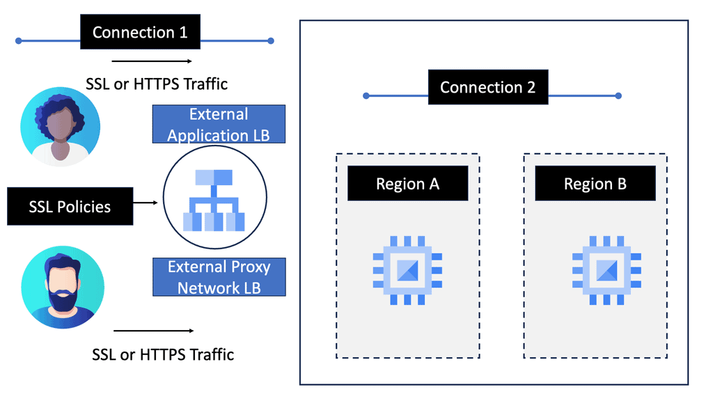
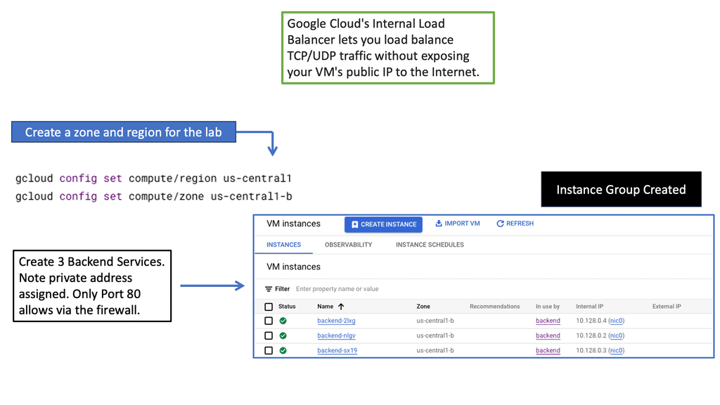
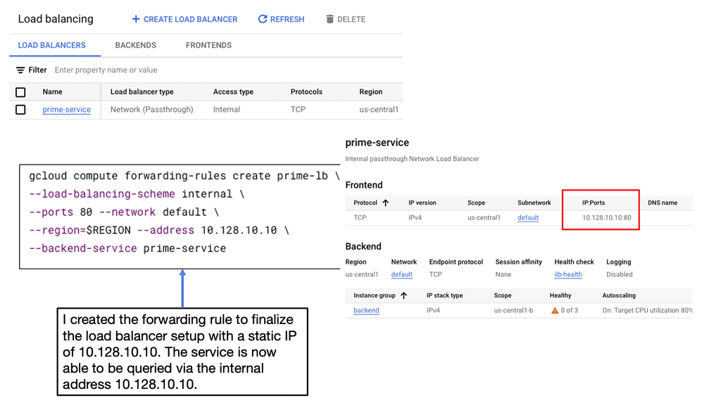
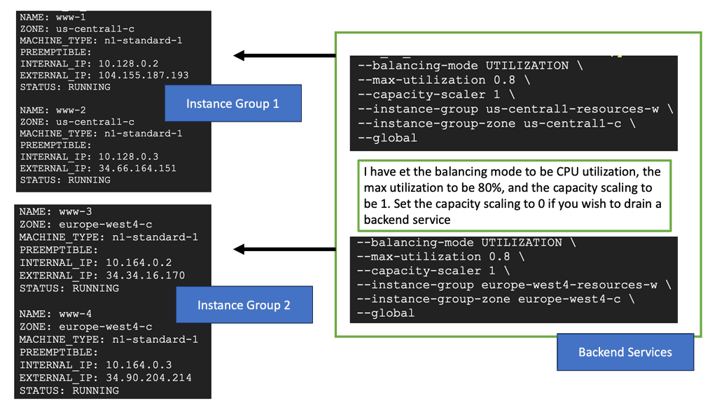
Network Load Balancer: Network Load Balancer is designed to distribute traffic at the transport layer (Layer 4) by forwarding requests to backend instances based on IP address and port. It is suitable for protocols such as TCP and UDP, making it ideal for handling non-HTTP workloads. Setting up a Network Load Balancer involves several steps, including configuring forwarding rules, backend services, and health checks.
HTTP Load Balancer: HTTP Load Balancer operates at the application layer (Layer 7) and provides advanced load balancing features for HTTP and HTTPS traffic. It offers content-based routing, SSL termination, session affinity, and URL mapping capabilities. To set up an HTTP Load Balancer, you need to define backend services, target pools, forwarding rules, and configure SSL certificates if necessary.
### The Need for Cross-Region Load Balancing
Cross-region load balancing is crucial for businesses with a global reach. It enables seamless user experiences by routing traffic to the closest available server, thus reducing latency and improving load times. Additionally, it provides redundancy, ensuring that if one region experiences an outage, traffic can be rerouted to other healthy regions, maintaining the application’s availability.
### Google Cloud’s Approach to Load Balancing
Google Cloud offers a robust suite of load balancing solutions that are designed to handle the complexities of cross-region traffic distribution. Google’s HTTP(S) load balancer is a fully distributed, software-defined, managed service that supports global load balancing with a single anycast IP address. It automatically routes incoming requests to the nearest healthy backend, ensuring optimal performance and high availability.
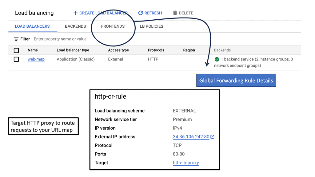
### Setting Up Cross-Region Load Balancing on Google Cloud
To implement cross-region HTTP load balancing on Google Cloud, you need to:
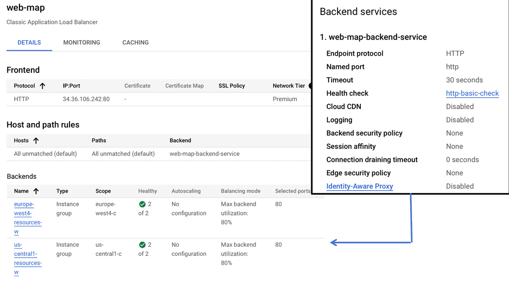
1. **Create a Load Balancer:** Use the Google Cloud Console to set up a new HTTP(S) load balancer. This involves configuring the frontend, backend, and health check settings.
2. **Configure Backend Services:** Define backend services that will distribute traffic to the instances in your chosen regions. You can also set up autoscaling to dynamically adjust the number of instances based on traffic demands.
3. **Set Up URL Maps and Host Rules:** Customize how traffic is routed by setting up URL maps and host rules. This allows you to direct traffic to specific services based on the URL path or host name.
4. **Test and Monitor:** Once your setup is complete, test the load balancer to ensure it’s distributing traffic as expected. Google Cloud provides monitoring tools to help track performance and detect any issues.
Understanding SD-WAN Traffic Steering
SD-WAN traffic steering intelligently directs network traffic across multiple paths to ensure optimal performance and reliability. It involves analyzing network conditions, application requirements, and other factors to make informed routing decisions. SD-WAN traffic steering provides enhanced performance and flexibility by dynamically routing traffic based on real-time conditions.
Load Balancing: Load balancing is a fundamental traffic steering technique in SD-WAN. It involves distributing traffic across multiple paths to avoid congestion and maximize bandwidth utilization. SD-WAN devices intelligently monitor network conditions and dynamically adjust traffic distribution, ensuring efficient utilization of available resources.
Application-Aware Routing: Traditional routing techniques treat all traffic equally, regardless of the application type or priority. However, SD-WAN introduces application-aware routing, where traffic is routed based on application requirements. By prioritizing critical applications and allocating network resources accordingly, SD-WAN optimizes performance and user experience.
Performance-Based Routing: SD-WAN leverages performance-based routing to dynamically select the best path for network traffic. This technique continuously monitors factors such as latency, jitter, and packet loss to assess the quality of each available path. SD-WAN ensures consistent and reliable performance by intelligently routing traffic through the most optimal path.
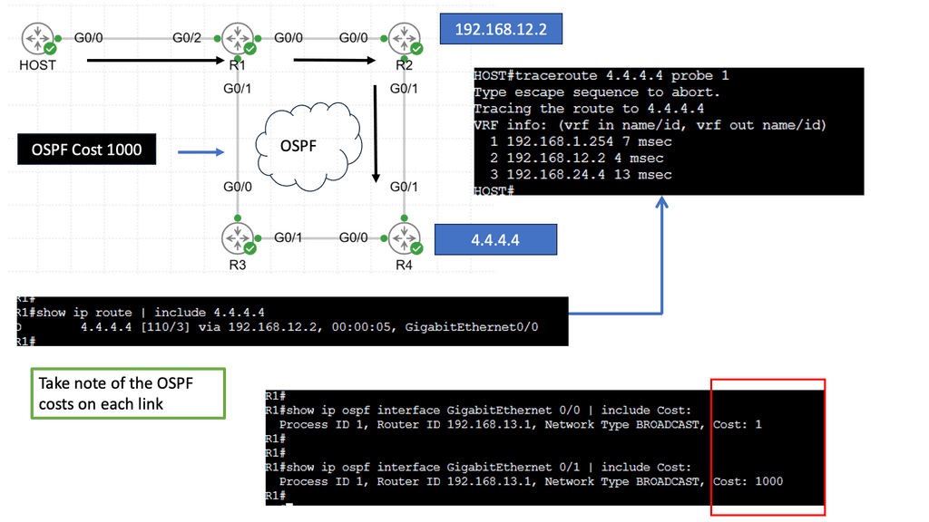
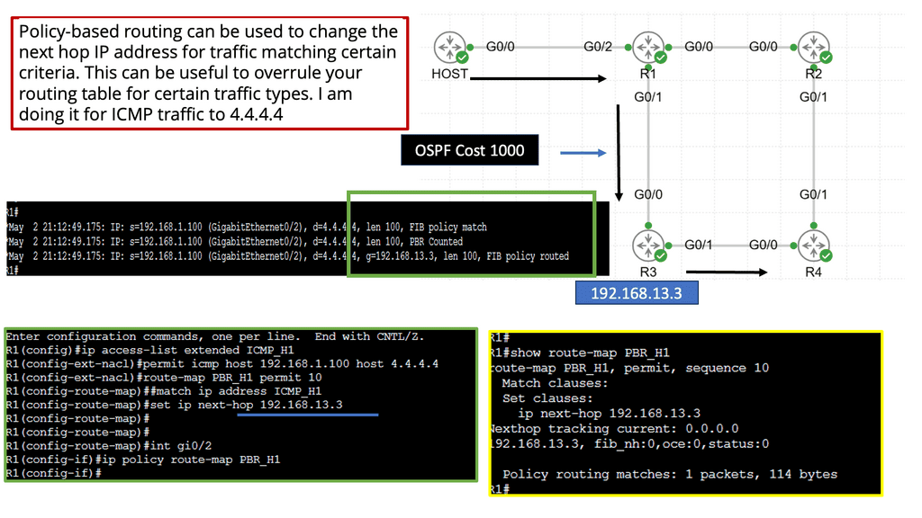
Policy-Based Routing: Policy-based routing allows network administrators to define specific rules and policies for traffic steering. These policies are based on factors such as application type, user groups, or security requirements. SD-WAN devices enforce these policies to route traffic according to the predefined rules, providing granular control over network traffic.
Example Steering Technology with PBR
### How Policy-Based Routing Works
Policy-Based Routing operates by defining a set of rules or policies that determine how packets are forwarded through the network. These policies are applied to traffic flows, allowing for customized routing paths rather than the default routes provided by traditional routing protocols. Network administrators can configure PBR to divert traffic according to specific needs, such as routing certain types of traffic over a high-speed link, bypassing congested paths, or implementing quality of service (QoS) requirements.
### Benefits of Policy-Based Routing
The primary advantage of PBR is its ability to tailor network traffic flows to meet specific business objectives. By customizing routing decisions, organizations can ensure that critical applications receive the necessary bandwidth and low latency, enhancing overall network performance. Moreover, PBR can contribute to cost savings by optimizing the use of available bandwidth and preventing unnecessary upgrades. It also enhances security by allowing sensitive data to be routed through secure paths.
### Implementing Policy-Based Routing
Implementing PBR involves several steps, starting with identifying the traffic that needs special handling. Network administrators must then define the policies that will govern how this traffic is to be routed. These policies are configured on routers or switches within the network. Monitoring and maintaining these policies is crucial to ensure they continue to align with organizational needs and network conditions.
### Challenges and Considerations
While PBR offers significant benefits, it also presents challenges. Configuring and maintaining PBR requires a deep understanding of network topology and traffic patterns. Incorrect configurations can lead to suboptimal routing and increased complexity in troubleshooting network issues. Additionally, PBR can add processing overhead to routers, potentially impacting performance if not managed properly.
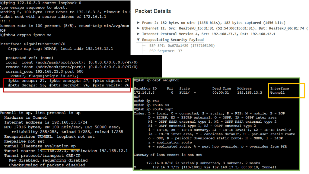
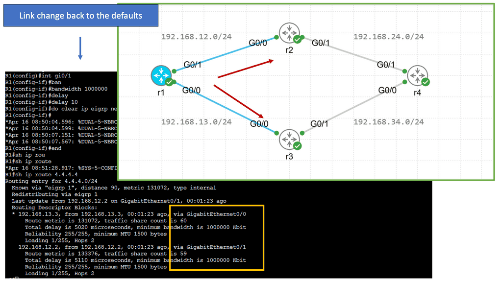
Understanding EIGRP Load Balancing
– EIGRP (Enhanced Interior Gateway Routing Protocol) is a dynamic routing protocol widely used in enterprise networks. Load balancing refers to the distribution of traffic across multiple paths, allowing for efficient utilization of available network resources. EIGRP load balancing achieves this by dividing traffic between numerous equal-cost paths, ensuring optimal utilization and enhancing network performance.
– Several factors must be considered to enable load balancing in EIGRP. First, the network topology must have multiple paths with equal metrics. This can be achieved by adjusting link costs or using equal-cost multipath (ECMP) techniques. Second, the router interfaces involved in load balancing should be configured to support it. This typically involves enabling EIGRP and specifying load-balancing parameters such as maximum-paths and variance.
– EIGRP offers different load-balancing algorithms to distribute traffic across multiple paths. These algorithms include per-packet load balancing, per-destination load balancing, and per-source/destination load balancing. Each algorithm has advantages and considerations, depending on the network requirements and characteristics. Understanding these algorithms is crucial for effective load-balancing implementation.
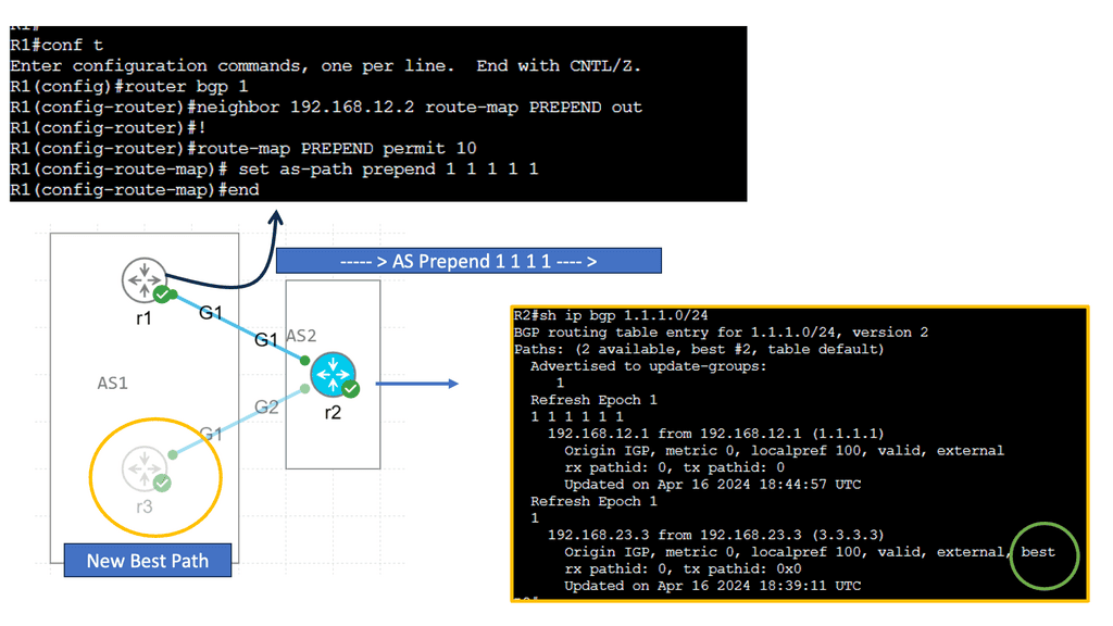
Understanding BGP AS Prepend
AS Prepending is a method for influencing routing path selection by adding additional AS numbers to the AS_PATH attribute. By manipulating the AS_PATH, network administrators can influence BGP routers to prefer specific paths. This technique is beneficial for directing traffic away from congested or underperforming links.
AS Prepending offers several advantages in network optimization. Firstly, distributing traffic across multiple paths allows for better load balancing. By strategically prepending AS numbers, you can encourage BGP routers to select alternate paths, optimizing network performance. Secondly, AS Prepending helps in traffic engineering, enabling you to control traffic flow and avoid congestion. Lastly, this technique improves network resilience by providing redundancy and failover capabilities.
Advanced Topics
Shortest-path routing
Every dynamic network backbone has some congested links, while others still need to be utilized. That’s because shortest-path routing protocols transmit traffic down the shortest path without regarding other network parameters, such as utilization and traffic demands. So, we need to employ application traffic engineering or traffic steering to use our network links.
Using Traffic Engineering (TE), we can redistribute packet flows to attain a more uniform distribution across all links in our network. Forcing traffic onto specific pathways lets you get the most out of your current network capacity while making it easier to deliver consistent service levels.
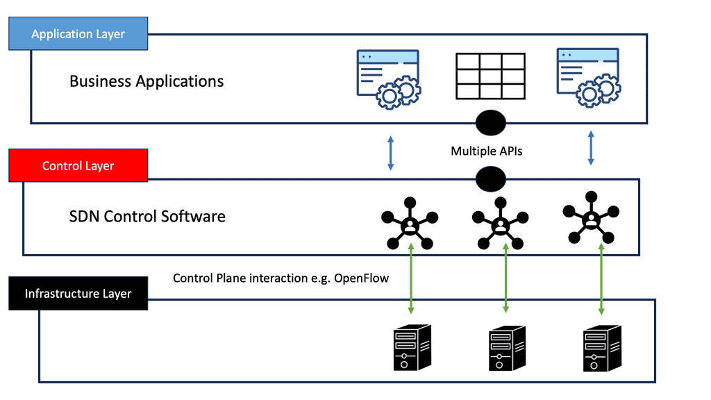
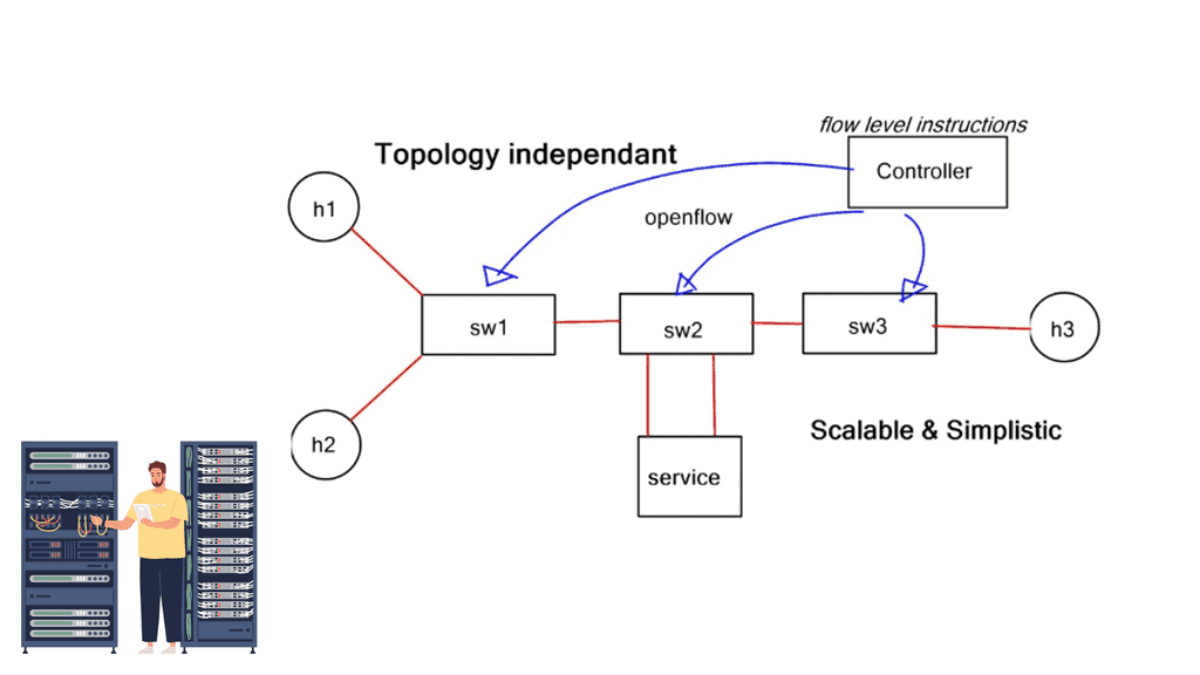
SDN-based Architecture
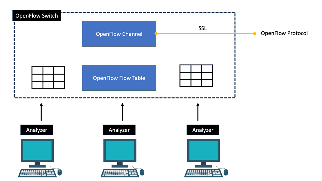
Many protocol combinations produce an SDN-based architecture to enable application traffic steering; native OpenFlow is only one of those protocols. Some companies view OpenFlow as a core SDN design component while others don’t even include it, aka BGP SDN controller and BGP SDN. For example, the Forwarding and Control Element Separation ( ForCES) working group has spent several years working on mechanisms for separating the control and data plane.
The role of OpenFlow
They created their southbound protocol and didn’t use OpenFlow to connect the data and control planes. On the other hand, NEC was one of the first organizations to take full advantage of the OpenFlow protocol. The market’s acceptance of SDN use cases has created products that fall into an OpenFlow or non-OpenFlow bucket. The following post discusses traffic steering that outright requires OpenFlow.
The OpenFlow protocol offers additional granular control to steer traffic through an ordered list of user-specific services. A task that traditional IP destination-based forwarding struggles to do efficiently. OpenFlow offers additional flow granularity and provides topology-independent service insertion required by network overlays, such as a VXLAN.
Understanding OpenFlow Traffic Steering
OpenFlow traffic steering involves intelligently directing network traffic flows within an SDN environment. By separating the control plane from the data plane, OpenFlow allows for centralized management and programmability of network devices. This enables granular control over routing decisions, flow prioritization, and traffic optimization.
Enhanced Network Flexibility: OpenFlow traffic steering empowers administrators to adapt and reconfigure their networks to meet changing demands dynamically. This flexibility improves scalability, reduces network congestion, and enhances overall network performance.
Efficient Traffic Management: With OpenFlow, traffic can be intelligently routed based on specific criteria such as quality of service (QoS), latency requirements, or security policies. This fine-grained control optimizes network utilization, minimizes packet loss, and improves end-to-end performance.
Simplified Network Operations: OpenFlow simplifies network operations by centralizing network control, reducing the complexity associated with traditional distributed routing protocols. Administrators can define traffic policies and implement changes across the network from a single management interface, thus streamlining network management tasks.
Implementing OpenFlow Traffic Steering
Network Infrastructure Requirements: Organizations need compatible network devices that support the OpenFlow protocol to implement OpenFlow traffic steering. These devices include OpenFlow-enabled switches and routers, which can be sourced from various vendors.
OpenFlow Controller Selection: It is crucial to select an appropriate OpenFlow controller. Popular choices include OpenDaylight, Ryu, and Floodlight. The OpenFlow controller acts as the brain of the network, managing traffic and enforcing policies based on predefined rules.
Rule Definition and Flow Configuration: Network administrators must define traffic flow rules within the OpenFlow controller. These rules specify how traffic should be handled, including routing decisions, QoS parameters, and any required packet modifications. Careful planning and rule design are essential to achieving desired traffic steering outcomes.
Related: You may find the following helpful post for pre-information.
The Role of Load Balancers:
Load balancing serves as the backbone of Application Traffic Steering. They act as intermediaries between clients and servers, receiving incoming requests and distributing them across multiple servers based on specific algorithms. These algorithms consider server load, response time, and availability to make informed decisions.
Application Traffic Steering Techniques:
1. Round Robin: This algorithm distributes traffic evenly across all available servers in a cyclic manner. While it is simple and easy to implement, it does not consider server load or response times, which may result in uneven distribution and suboptimal performance.
2. Least Connections: This algorithm directs traffic to the server with the fewest active connections at a given time. It ensures optimal resource utilization by distributing traffic based on the server’s current load. However, it doesn’t consider server response times, which may lead to slower performance on heavily loaded servers.
3. Weighted Round Robin: This algorithm assigns weights to servers based on their capabilities and performance. Servers with higher weights receive a larger share of traffic, enabling organizations to prioritize specific servers over others based on their capacity.
Multicast Traffic Steering
Multicast traffic steering is a technique for efficiently directing data packets to multiple recipients simultaneously. It is beneficial in scenarios where a single source needs to transmit data to various destinations. Instead of sending individual copies of the data to each recipient, multicast traffic steering enables the source to transmit a single copy efficiently distributed to all interested recipients.
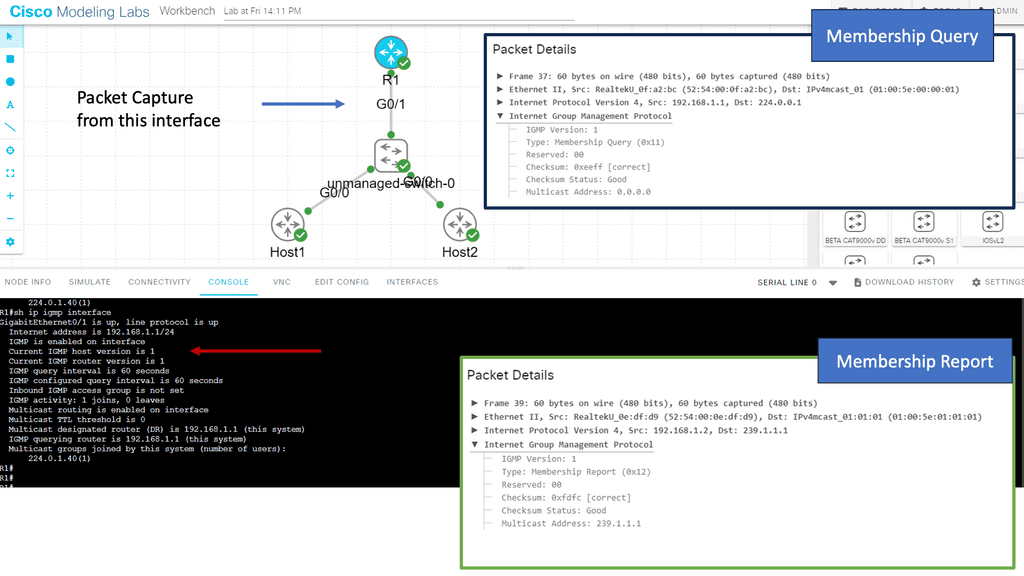
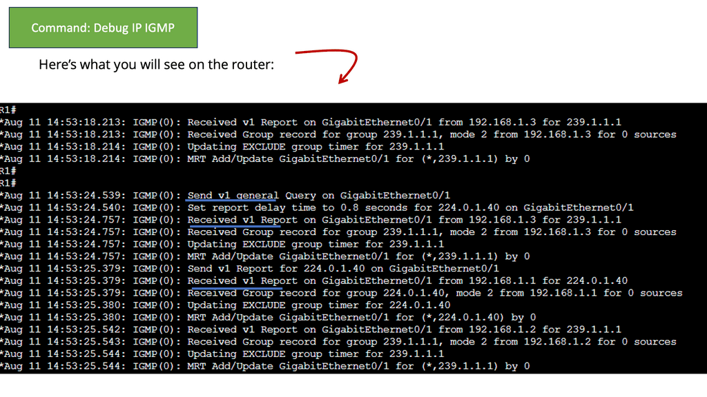
Guide on IGMPv1
IGMPv1 is a communication protocol that enables hosts on an Internet Protocol (IP) network to join and leave multicast groups. Multicast groups allow the simultaneous transmission of data packets from a single sender to multiple recipients.
By utilizing IGMPv1, hosts can efficiently manage their participation in multicast groups and receive relevant data from senders.
Below, we have one router and two hosts. We will enable multicast routing and IGMP on the router’s Gigabit 0/1 interface.
- First, we enabled multicast routing globally; this is required for the router to process IGMP traffic.
- We enabled PIM on the interface. PIM is used for multicast routing between routers and is also required for the router to process IGMP traffic.
**Benefits of Multicast Traffic Steering**
1. Bandwidth Efficiency:
Multicast traffic steering reduces network congestion and optimizes bandwidth utilization. By transmitting a single copy of the data, it minimizes the duplication of data packets, resulting in significant bandwidth savings. This is especially advantageous in scenarios where large volumes of data must simultaneously be transmitted to multiple destinations, such as video streaming or software updates.
2. Scalability:
In networks with many recipients, multicast traffic steering ensures efficient data delivery without overwhelming the network infrastructure. Instead of creating a separate unicast connection for each recipient, multicast traffic steering establishes a single multicast group, reducing the burden on the network and enabling seamless scalability.
3. Reduced Network Latency:
Multicast traffic steering reduces network latency by eliminating the need for multiple unicast connections. Data packets are delivered directly to all interested recipients, minimizing the delay caused by establishing and maintaining individual connections for each recipient. This is particularly crucial for real-time applications, such as video conferencing or live streaming, where low latency is essential for a seamless user experience.
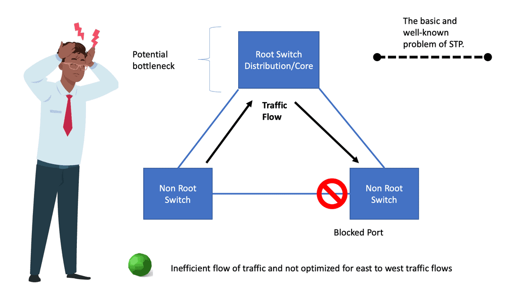
Layer 2 and Layer 3 Service Insertion
Example: Traditional Layer 2
In a flat Layer 2 environment, everybody can reach each other by their MAC address. There is no IP routing. If you want to intercept traffic, the switch in the middle must intercept and forward to a service device, such as a firewall.
The firewall doesn’t change anything; it’s a transparent bump in the wire. You would usually insert the same service in both directions so the firewall will see both directions of the TCP session. Service insertion at Layer 2 is achieved with VLAN chaining.
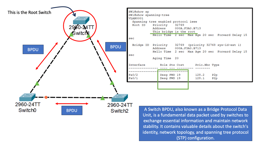
For example, VLAN-1 is used on one side and VLAN-2 on the other; different VLAN numbers link areas. VLAN chaining is limited and impossible to implement for individual applications. It is also an excellent source for creating network loops. You may encounter challenges when firewalls or service nodes do not pass the Bridge Protocol Data Unit (BPDU). Be careful to use this for large-scale service insertion production environments.
Example: Layer 3 Service Insertion
Layer 3 service insertion is much safer as forwarding is based on IP headers, not Layer 2 MAC addresses. Layer 3 IP headers have a “time-to-live” field that prevents loops from looping around the network. Layer 2 frames are redirected to a transparent or inter-subnet appliance.
This means the firewall device can do a MAC header rewrite on layer 2, or if the firewall is placed in different subnets, the MAC rewrite would be automatic as you will be doing layer 3 forwardings. Layer 3 service insertion is typically implemented with Policy-Based Routing (PBR).
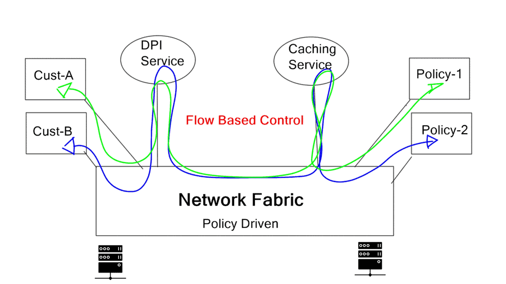
“User-specific services may include firewall, deep packet inspection, caching, WAN acceleration and authentication.”
Application traffic steering, service function chaining, and dynamic service insertion
Application traffic steering, service function chaining, and dynamic service insertion functionally mean the same thing. They want to insert networking functions based on endpoints or applications in the forwarding path.
Service chaining applies a specific list of ordered services (service changing) to individual traffic flows. The main challenge is the ability to steer traffic to various devices. Such devices may be physical appliances or follow the Network Function Virtualization (NFV) format.
Designing with traditional mechanisms leads to cumbersome configurations and multiple device touchpoints. For example, service appliances that need to intercept and analyze traffic could be centralized in a data center or service provider network. Service centralization results in users’ traffic “tromboning” to the central service device for interaction.
Traffic tromboning
Traffic tromboning may not be an issue for data center leaf and spine architecture with equidistant endpoints. However, other aggregated network designs that don’t follow the leaf and spine model may run into interesting problems. A central service network point also represents a “choking point” and may increase path latency. Service integration should be flexible and not designed with a “meet me” architecture.
The requirement for “flow” level granularity
Traditional routing is based on destination-based forwarding and cannot provide the granularity needed for topology-independent traffic steering. You may implement tricks with PBR and ACL, but they increase complexity and have vendor-specific configurations. Efficient traffic steering requires a granular “flow” level of interaction, which is not offered by default destination-based forwarding.
The requirement for large-scale cloud networks drives multitenancy, and network overlays are becoming the defacto technology used to meet this requirement. Network overlays require new services to be topology-independent.
Unfortunately, IP routing is limited, and different types of traffic going to the same destination cannot be distinguished. Traffic steering based on traditional Layer 2 or 3 mechanisms is inefficient and does not allow dynamic capabilities.

SDN Adoption
A single OpenFlow rule pushed down from the central SDN controller provides the same effect as complex PBR and ACL designs. Traffic steering is accomplished with OpenFlow at an IP destination or IP flow layer of granularity. This dramatically simplifies network operations as there is no need for PBR and ACL configurations. There is less network and component state as all the rules and intelligence are maintained at the SDN central controller.
A holistic viewpoint enables singular points for configuration, not numerous touchpoints throughout the network. A virtual switch, such as the Open vSwitch, can be used for data. It is a multi-layered switch that is highly well-featured.
There are alternatives for pushing ACL rules down to network devices, such as RFC 5575 and Dissemination of Flow Specification Rules. It works with a BGP control plane (BGP flow spec) that can install rules and ACL to network devices.
One significant difference between BGP flow spec and OpenFlow for traffic steering is that the OpenFlow method has a central control policy. BGP flow spec consists of several distributed devices, and configuration changes will require multiple touchpoints in the network.
Closing Points: Application Traffic Steering
Application traffic steering plays a pivotal role in this process, acting as a sophisticated guide that directs data packets across networks to optimize performance. This technique ensures that application traffic is evenly distributed and managed effectively, preventing bottlenecks and improving user experience.
At its core, traffic steering involves a range of techniques such as load balancing, Quality of Service (QoS) policies, and intelligent routing. Load balancing distributes incoming network traffic across multiple servers, ensuring no single server becomes overwhelmed. QoS policies prioritize certain types of traffic, ensuring that critical applications receive the bandwidth they need, even during peak times. Intelligent routing, on the other hand, selects the optimal path for data packets based on current network conditions, ensuring efficient data delivery.
Implementing effective traffic steering provides numerous benefits. For one, it enhances application performance by reducing latency and avoiding congestion. This is especially vital for businesses that rely on real-time data processing and cloud-based applications. Additionally, it improves scalability, allowing networks to handle increased loads without compromising performance. Furthermore, traffic steering can lead to cost savings by optimizing resource utilization and minimizing the need for additional infrastructure investments.
Despite its benefits, traffic steering does come with its challenges. One major hurdle is the complexity of managing traffic across hybrid and multi-cloud environments. With data distributed across various platforms, maintaining a cohesive steering strategy can be daunting. However, leveraging automation and AI-driven solutions can significantly streamline this process, providing real-time analytics and adaptive steering capabilities that respond to dynamic network conditions.