Understanding Geographic Routing in Data Centers
In today’s hyper-connected world, data centers play a crucial role in ensuring seamless digital experiences. Geographic routing within data centers refers to the strategic distribution of data across various global locations to optimize performance, enhance reliability, and reduce latency. This process involves directing user requests to the nearest or most efficient data center based on their geographical location. By understanding and implementing geographic routing, companies can significantly improve the speed and quality of their services.
**The Importance of Geographic Proximity**
One of the primary reasons for geographic routing is to minimize latency—the delay between a user’s request and the response from the server. When data centers are geographically closer to the end-users, the time taken for data to travel back and forth is reduced. This proximity not only accelerates the delivery of content and services but also enhances user satisfaction by providing a smoother and faster experience. In a world where milliseconds matter, especially in sectors like finance and gaming, geographic routing becomes a game-changer.
**Challenges and Considerations**
While geographic routing offers numerous benefits, it also presents several challenges. One major consideration is the complexity of managing multiple data centers spread across the globe. Companies must ensure consistent data synchronization, security, and compliance with local regulations. Additionally, unforeseen events such as natural disasters or political instability can impact data center operations. Therefore, businesses need to adopt robust disaster recovery plans and flexible routing algorithms to adapt to changing circumstances.
**Technological Innovations Driving Geographic Routing**
Recent advancements in technology have significantly enhanced geographic routing capabilities. Machine learning algorithms can now predict traffic patterns and dynamically adjust routing paths to optimize performance. Moreover, edge computing—bringing computation and data storage closer to the location of need—further complements geographic routing by reducing latency and bandwidth usage. As these technologies continue to evolve, they promise to make geographic routing even more efficient and reliable.
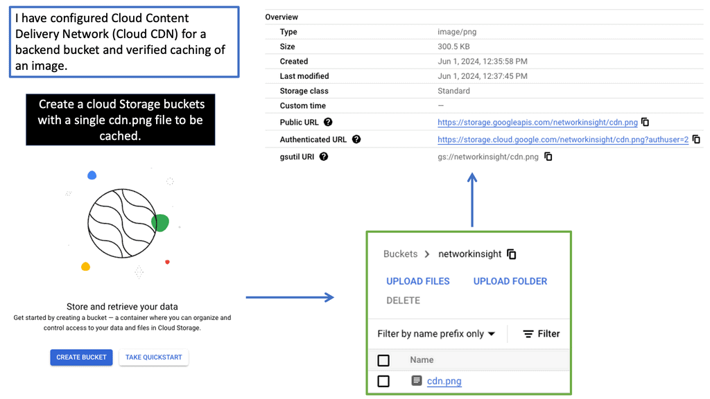
Google Cloud CDN
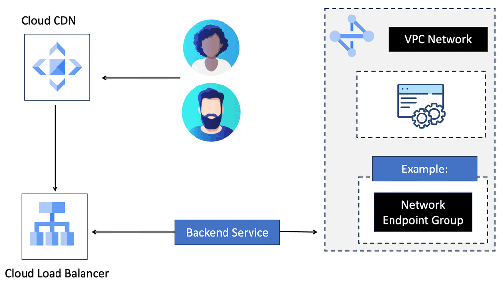
A CDN is a globally distributed network of servers that stores and delivers website content to users based on their geographic location. By caching and serving content from servers closest to the end users, CDNs significantly reduce latency and enhance the overall user experience.
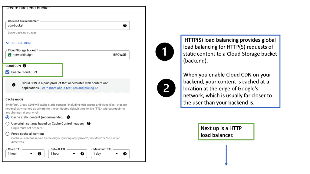
Google Cloud CDN is a robust and scalable CDN solution offered by Google Cloud Platform. Built on Google’s global network infrastructure, it seamlessly integrates with other Google Cloud services, providing high-performance content delivery worldwide. With its vast network of edge locations, Google Cloud CDN ensures low-latency access to content, regardless of the user’s location.
– Global Edge Caching: Google Cloud CDN caches content at edge locations worldwide, ensuring faster retrieval and reduced latency for end-users.
– Security and Scalability: With built-in DDoS protection and automatic scaling, Google Cloud CDN guarantees the availability and security of your content, even during traffic spikes.
– Intelligent Caching: Leveraging machine learning algorithms, Google Cloud CDN intelligently caches frequently accessed content, further optimizing delivery and reducing origin server load.
– Real-time Analytics: Google Cloud CDN provides comprehensive analytics and monitoring tools to help you gain insights into your content delivery performance.
Routing IP addresses: The Process
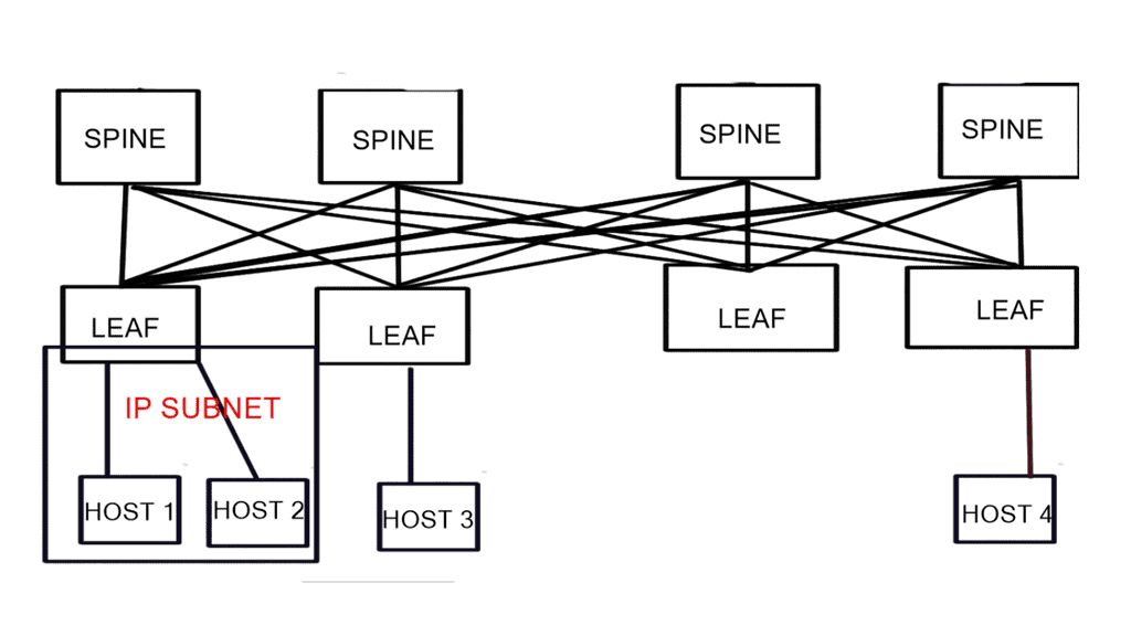
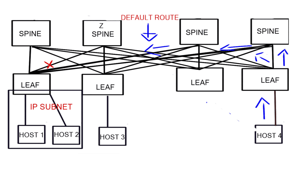
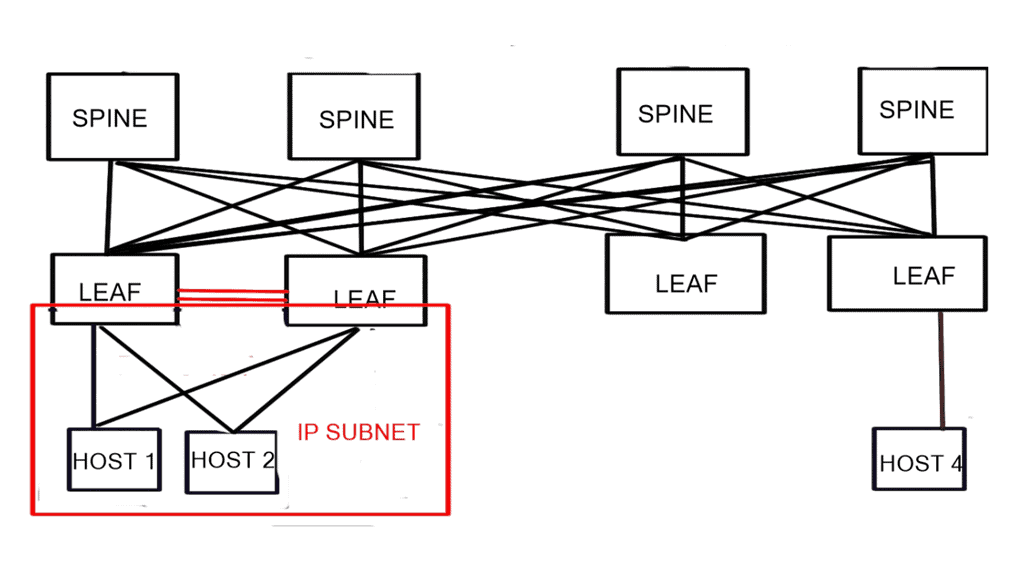
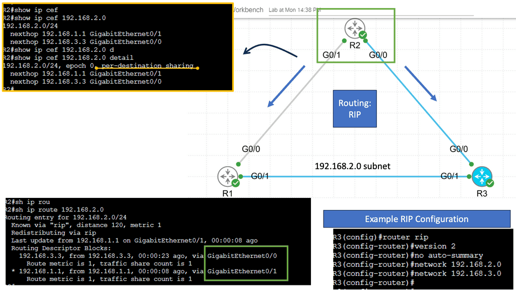
In IP routing, routers must make packet-forwarding decisions independently of each other. Therefore, IP routers are only concerned with finding the next hop to a packet’s final destination. The IP routing protocol is myopic in this sense. IP’s myopia allows it to route around failures easily, but it is also a weakness. In most cases, the packet will be routed to its destination via another router unless the router is on the same subnet (more on this later).
In the routing table, a router looks up a packet’s destination IP address to determine the next hop. A packet is then forwarded to the network interface returned by this lookup by the router.
RIB and the FIB
All the different pieces of information learned from all the other methods (connected, static, and routing protocols) are stored in the RIB. A software component called the RIB manager selects all these different methods. Every routing protocol has a unique number called the distance2. If more than one protocol has the same prefix, the RIB manager picks the protocol with the lowest distance. The shortest distance is found on connected routes. Routes obtained via a routing protocol have a greater distance than static routes.
Routing to a data center
Let us address how users are routed to a data center. Well, there are several data center site selection criteria or even checklists that you can follow to ensure your users follow the most optimal path and limit sub-optimal routing. Distributed workloads with multi-site architecture open up several questions regarding the methods for site selection, path optimization for ingress/egress flows, and data replication (synchronous/asynchronous) for storage.
### Understanding Routing Protocols
Routing protocols are the rules that dictate how data is transferred from one point to another within a network. They are the unsung heroes of the digital world, enabling seamless communication between servers, devices, and users. In data centers, common routing protocols include BGP (Border Gateway Protocol), OSPF (Open Shortest Path First), and EIGRP (Enhanced Interior Gateway Routing Protocol). Each protocol has its unique strengths, making them suitable for different network configurations and requirements.
Border Gateway Protocol (BGP) is a cornerstone of internet routing, and its importance extends to data centers. BGP is designed to manage how packets are routed across the internet by exchanging routing information between different networks. In a data center environment, BGP helps in optimizing paths, ensuring redundancy, and providing failover capabilities. This makes it indispensable for maintaining the robustness and resilience of network infrastructure.
### Understanding Border Gateway Protocol (BGP)
At the heart of data center routing lies the Border Gateway Protocol, or BGP. BGP is the protocol used to exchange routing information across the internet, making it a cornerstone of global internet infrastructure. It enables data centers to communicate with each other and decide the best routes for data packets. What makes BGP unique is its ability to determine paths based on various attributes, which helps in managing network policies and ensuring data is routed through the most efficient paths available.
### How BGP Enhances Data Center Efficiency
BGP doesn’t just facilitate communication between data centers; it enhances their efficiency. By allowing data centers to dynamically adjust routing paths, BGP helps in managing traffic loads, avoiding congestion, and preventing outages. For example, if a particular route becomes congested, BGP can reroute traffic through alternative paths, ensuring that data continues to flow smoothly. This adaptability is essential for maintaining the performance and reliability of data centers.
BGP AS Prepending
AS Path prepending is a simple yet powerful technique for manipulating BGP route selection. By adding additional AS numbers to the AS Path attribute, network administrators can influence the inbound traffic flow to their network. Essentially, the longer the AS Path, the less attractive the route appears to neighboring ASes, leading to traffic routed through alternate paths.
AS Path prepending offers several benefits for network administrators. Firstly, it provides a cost-effective way to balance inbound traffic across multiple links, thereby preventing congestion on a single path. Secondly, it enhances network resilience by providing redundancy and alternate paths in case of link failures. Lastly, AS Path prepending can be used strategically to optimize outbound traffic flow and improve network performance.
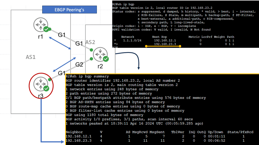
In my example, AS 1 wants to ensure traffic enters the autonomous system through R2. We can add our autonomous system number multiple times, so the as-path becomes longer. Since BGP prefers a shorter AS path, we can influence our routing. This is called AS path pretending. Below, the default behavior is shown without pretending to be configured.
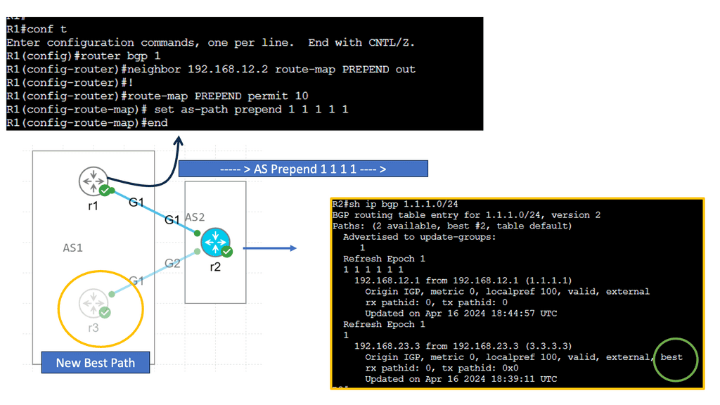
First, create a route map and use set as-path prepend to add your own AS number multiple times. Don’t forget to add the route map to your BGP neighbor configuration. It should be outbound since you are sending this to your remote neighbor! Let’s check the BGP table! Now we see that 192.168.23.3 is our next-hop IP address. The AS Path for the second entry has also become longer. That’s it!
Distributing the load
Furthermore, once the content is distributed to multiple data centers, you need to manage the request for the distributed content and the load by routing users’ requests to the appropriate data center. Routing in the data center is known as content routing. Content routing takes a user’s request and sends it to the relevant data center.
Note on Content Routing
Content routing is a critical subset of data center routing, focusing on directing user requests to the most appropriate server based on various factors such as location, server load, and network conditions. This approach not only enhances user experience by reducing latency but also optimizes resource utilization within the data center. Content routing relies on advanced algorithms and technologies like load balancing and Anycast networking to make real-time decisions about the best path for data to travel.
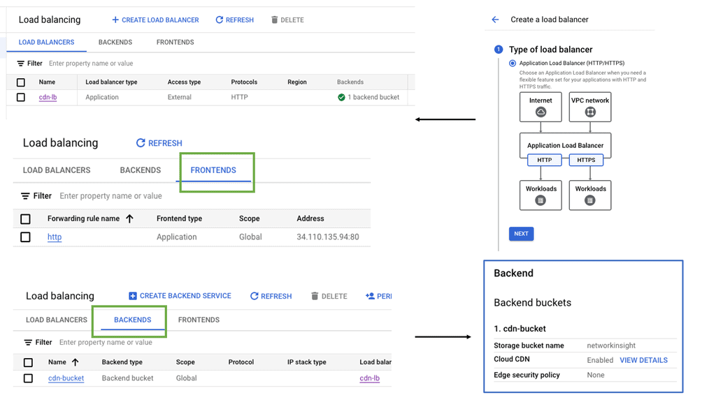
Example: Distributing Load with Load Balancing
**The Role of Load Balancing**
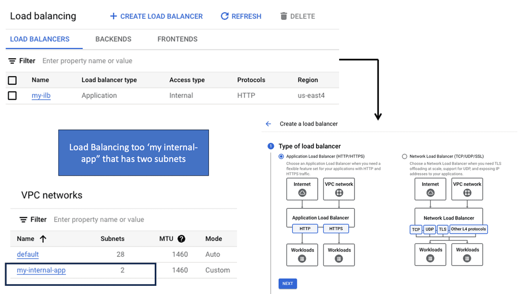
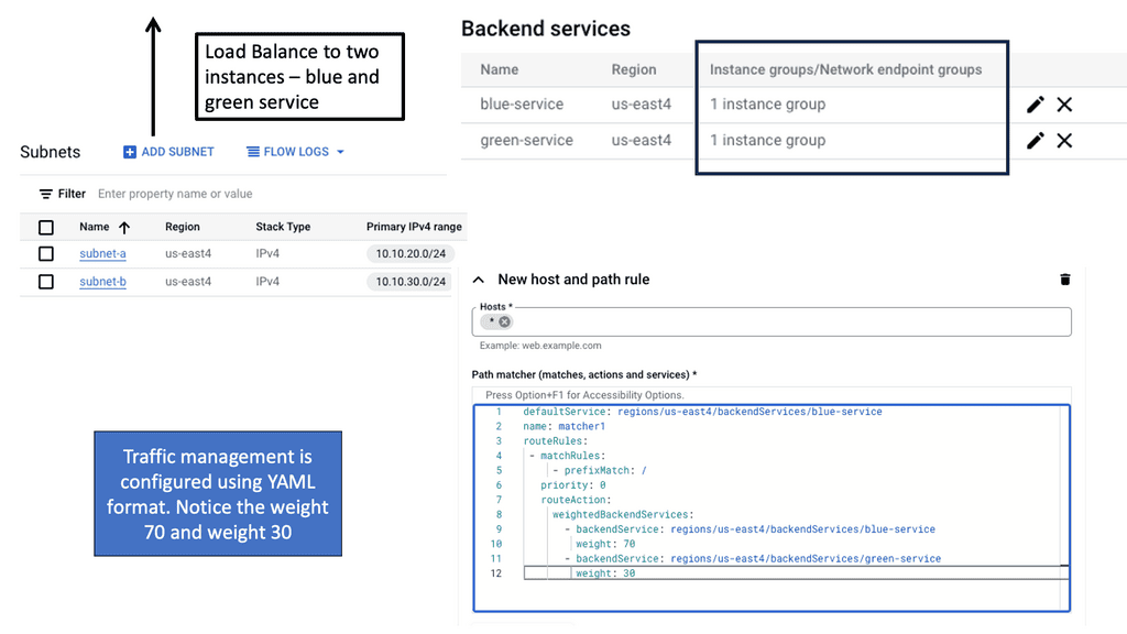
Load balancing is a critical aspect of data center routing. It involves distributing incoming network traffic across multiple servers to ensure no single server becomes overwhelmed. This distribution improves the availability and reliability of applications, enhances user experience, and reduces downtime. Load balancers also monitor server health and reroute traffic if a server becomes unavailable, maintaining seamless connectivity.
**Types of Load Balancing**
There are several types of load balancing methods, each with its own advantages:
1. **Round Robin:** This method distributes requests sequentially across servers, ensuring an even distribution.
2. **Least Connections:** Directs traffic to the server with the fewest connections, optimizing resource use.
3. **IP Hash:** Routes requests based on a unique hash of the client’s IP address, ensuring consistent connections to the same server.
Example Data Center Peering: VPC Peering
**The Importance of Efficient Routing**
Efficient routing to a data center is essential for maintaining the speed and reliability of network services. As businesses increasingly rely on cloud-based applications and services, the demand for seamless connectivity continues to grow. Poor routing can lead to latency issues, bottlenecks, and even outages, which can be detrimental to business operations. By optimizing routing paths, organizations can improve performance and ensure a smooth flow of data.

**VPC Peering: A Key Component**
Virtual Private Cloud (VPC) peering is a vital aspect of data center routing. It allows the interconnection of two VPCs, enabling them to communicate as if they were on the same network. This setup enhances the flexibility and scalability of network architectures, making it easier for businesses to manage workloads across multiple environments. VPC peering eliminates the need for complex gateways, reducing latency and potential points of failure.

Before you proceed, you may find the following post helpful:
Data Center Interconnect (DCI)
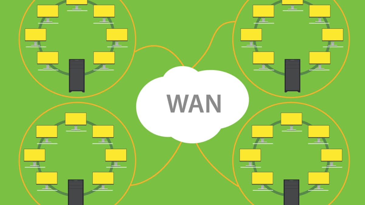
Before we get started on your journey with a data center site selection checklist, it may be helpful to know how data centers interconnect. Data Center Interconnect (DCI) solutions have been known for quite some time; they are mainly used to help geographically separated data centers.
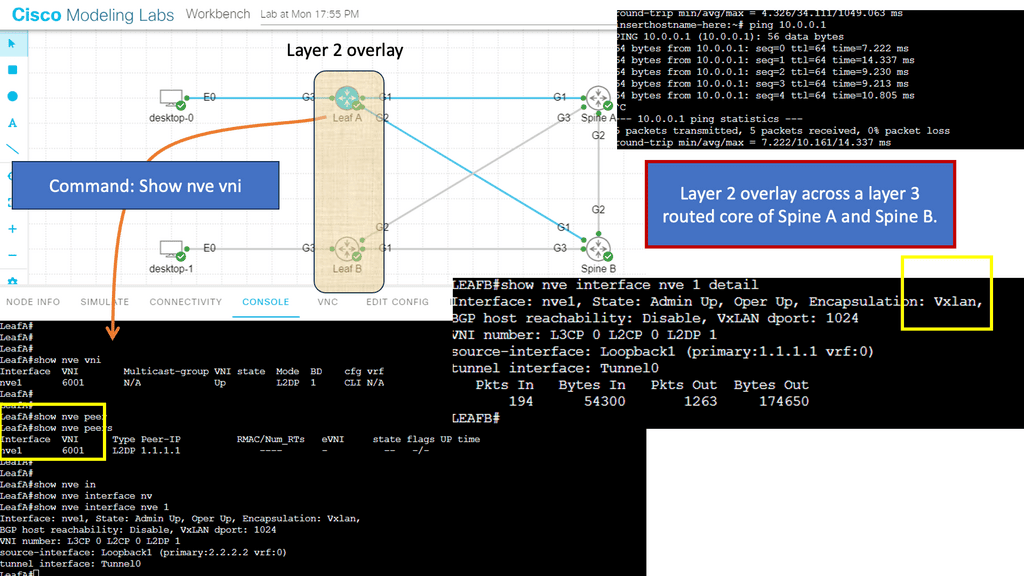
Layer 2 extensions might be required at different layers in the data center to enable the resiliency and clustering mechanisms offered by the other applications. For example, Cisco’s OTV can be used as a DCI solution.
OTV provides Layer 2 extension between remote data centers using MAC address routing. A control plane protocol exchanges MAC address reachability information between network devices, providing the LAN extension functionality. This has a tremendous advantage over traditional data center interconnect solutions, which generally depend on data plane learning and flooding across the transport to learn reachability information.
Data Center Site Selection Criteria
- Proximity-based site selection
Different data center site selection criteria can route users to the most optimum data centers. For example, proximity-based site selection involves selecting a geographically closer data center, which generally improves response time. Additionally, you can route requests based on the data center’s load or application availability.
Things become interesting when workloads want to move across geographically dispersed data centers while maintaining active connections to front-end users and backed systems. All these elements put increasing pressure on the data center interconnect ( DCI ) and the technology used to support workload mobility.
- Multi-site load distribution & site-to-site recovery
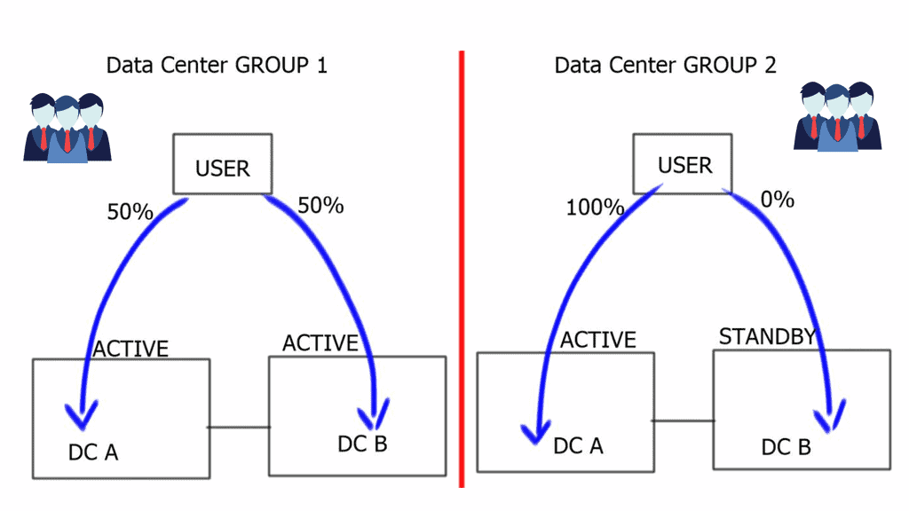
Data center site selection can be used for site-to-site recovery and multi-site load distribution. Multi-site load distribution requires a mechanism that enables the same application to be accessed by both data centers, i.e., an active/active setup.
For site-to-site load balancing, you must use an active/active scenario ( also known as hot standby ) in which both data centers host the same active application. Logically active / standby means that some applications will be active on one site while others will be on standby at the other sites.

Data center site selection is vital, and determining which data center to target your request can be based on several factors, such as proximity and load. Different applications will prefer different site selection mechanisms. For example, video streaming will choose the closest data center ( proximity selection ). Other types of applications would prefer data centers that are least loaded, and others work efficiently with the standard round-robin metric. The three traditional methods for data center site selection criteria are Ingress site selection DNS-based, HTTP redirection, and Route Health Injection.
Data Center Site Selection Checklist
Hypertext Transfer Protocol ( HTTP ) redirection
Applications can have built-in HTTP redirection in their browsers. This enables them to communicate with a secondary server if the primary server is not available. When redirection is required, the server will send an HTTP Redirect ( 307 ) to the client and send the client to the correct site with the required content. One advantage of this mechanism is that you have visibility into the requested content, but as you have probably already guessed, it only works with HTTP traffic.

DNS-based request routing
DNS-based request routing, or DNS load balancing, distributes incoming network traffic across multiple servers or locations based on the DNS responses. Traditionally, DNS has been primarily used to translate human-readable domain names into IP addresses. However, DNS-based request routing can now be vital in optimizing network traffic flow.
**How does it work?**
When a user initiates a request to access a website or application, their device sends a DNS query to a DNS resolver. Instead of providing a single IP address in response, the DNS resolver returns a list of IP addresses associated with the requested domain. Each IP address corresponds to a different server or location that can handle the request.
The control point for geographic load distribution in DNS-based request routing resides within DNS. DNS-based request routing uses DNS for both site-to-site recovery and multi-site load distribution. A DNS request, either recursive or iterative, is accepted by the client and directed to a data center based on configurable parameters. This provides the ability to distribute the load among multiple data centers with an active/active design based on criteria such as least loaded, proximity, round-robin, and round-trip time ( RTT ).
The support for legacy applications
DNS-based request routing becomes challenging if you have to support legacy applications without DNS name resolution. These applications have hard-coded IP addresses used to communicate with other servers. When there is a combination of legacy and non-legacy applications, the solution might be to use DNS-based request routing and IGP/BGP.
Another caveat for this approach is that the refresh rate for the DNS cache may impact the convergence time. Once a VM moves to the secondary site, there will also be increased traffic flow on the data center interconnect link—previously established connections are hairpinned.
Route Health Injection ( RHI )
Route Health Injection (RHI) is a method for improving network resilience by dynamically injecting alternative routes. It involves monitoring network devices and routing protocols to identify potential failures or performance degradation. By preemptively injecting alternative routes, RHI enables networks to reroute traffic and maintain optimal connectivity quickly.
How does Route Health Injection work?
Route Health Injection operates by continuously monitoring the health of network devices and analyzing routing protocol information. It leverages various metrics such as latency, packet loss, and link utilization to assess the overall health of network paths. When a potential issue is detected, RHI dynamically injects alternative routes to bypass the affected network segment, allowing traffic to flow seamlessly.
RHI is implemented in front of the application and, depending on its implementation, allows the same address or a different address to be advertised. It’s a route injected by a local load balancer that influences the ingress traffic path. RHI injects a static route when the VIP ( Virtual IP address ) becomes available and withdraws the static route when the VIP is no longer active. The VIP is used to represent an application.
A key point: Data center active-active scenario
Route Health Injection can be used for an active/active scenario as both data centers can use the same VIP to represent the server cluster for each application. RHI can create a lot of churns as routes are constantly being added and removed. If the number of supported applications grows, the network’s number of network host routes grows linearly. The decision to use RHI should come down to the scale and size of the data center’s application footprint.
RHI is commonly used on Intranets as the propagation of more specifics is not permitted on the Default Free Zone ( DFZ ). Specific requirements require RHI to be used with BGP/IGP for external-facing clients. Due to the drawbacks of DNS caching, RHI is often preferred over DNS solutions for Internet-facing applications.
A quick point: Ansible Automation
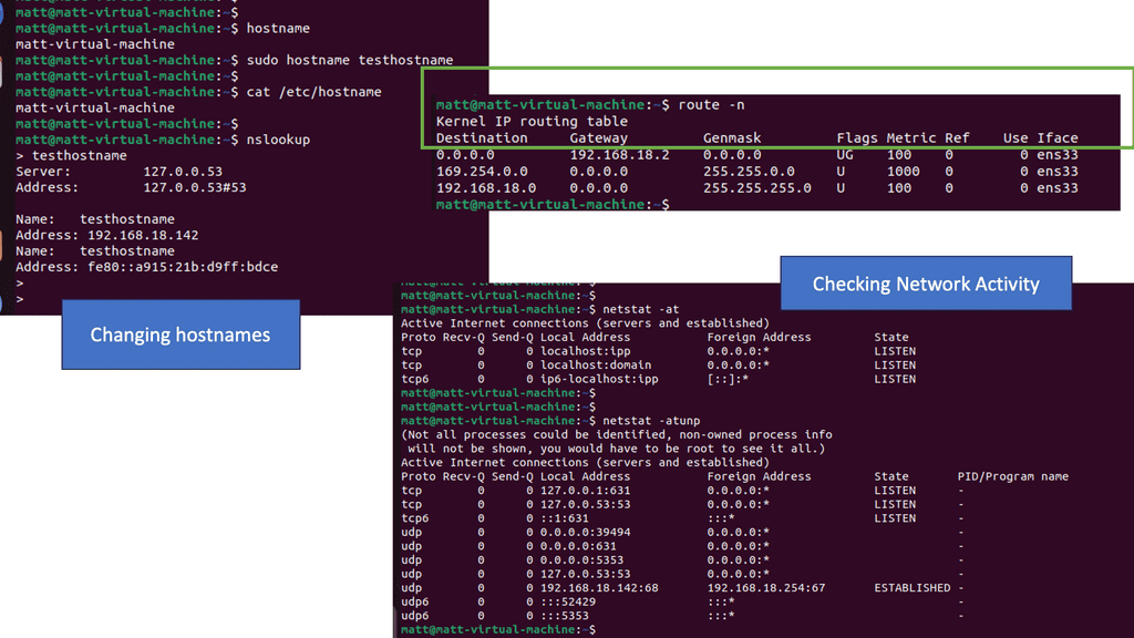
Ansible could be a good automation tool for bringing automation into the data center. Ansible can come from Ansible CLI, with Ansible Core, or a platform approach with Ansible Tower. Can these automation tools assist in our data center operations? Ansible variables can be used to remove site-specific information to make your playbooks more flexible.
For data center configuration or simply checking routing tables, you can have a single playbook that uses Ansible variables to perform operations on both data centers. I use this to check the routing tables of each data center. Once playbook using Ansible variables against one inventory for all my data centers. This can quickly help you when troubleshooting data center site selection.
BGP AS prepending
This can be used for active / standby site selection, not a multi-load distribution method. BGP uses the best path algorithm to determine the best Path to a specific destination. One of those steps that all router manufacturers widely use is AS Path—the lower the number of ASs in the path list, the better the route.
Specific routes are advertised from both data centers, with additional AS Paths added to the secondary site’s routes. When BGP goes through its site selection processes, it will choose the Path with the least AS Paths, i.e., the primary site without AS Prepending.
BGP conditional advertisements
BGP Conditional Advertisements are helpful when you are concerned that some manufacturers may have AS Path explicitly removed. A condition must be met with conditional route advertisement before an advertisement occurs. The routers on the secondary site monitor a set of prefixes located on the first site, and when those prefixes are not reachable at the first site, the secondary sites begin to advertise.
Its configuration is based on community”no-export” and iBGP between the sites. If routes were redistributed between BGP > IGP and advertised to the IBGP peer, the secondary site would advertise those routes, defeating the purpose of a conditional advertisement.
The RHI method used internally or externally with BGP is proper when using IP as the site selection method. For example, this may be the case when you have hard-coded IP addresses in the application used primarily with legacy applications or are concerned about DNS caching issues. Site selection based on RHI and BGP requires no changes to DNS.
However, its main drawback is that it cannot be used for active/active data centers and is primarily positioned as an active / standby method. This is because there is only ever one routing table entry in the routing table.
Additionally, for the final data center site selection checklist. There are designs where you can use IP Anycast in conjunction with BGP, IGP, and RHI to achieve an active/active scenario, and I will discuss this later. With this setup, there is no need for BGP conditional route advertisement or AS Path prepending.
Closing Points: Data Center Selection
Strategic routing is essential for optimizing network performance and ensuring that data reaches its destination quickly and efficiently. With the ever-increasing demand for faster internet speeds and lower latency, data centers need to be strategically located and correctly interconnected. Routing decisions are based on various factors, including geographical proximity, load balancing, and redundancy. By intelligently directing traffic, companies can ensure optimal performance and user satisfaction.
One of the primary considerations in data center routing is load balancing. This technique involves distributing incoming network traffic across multiple servers or data centers to ensure no single server becomes overwhelmed. Load balancing not only enhances the speed and efficiency of data processing but also provides redundancy, ensuring that if one server goes down, others can take over. This seamless transfer of data minimizes downtime and maintains the continuity of services.
Redundancy is a critical factor in ensuring the reliability of data center operations. By having multiple routes to reach a data center, companies can avoid potential disruptions caused by network failures. Redundant pathways ensure that even if one connection is lost, data can still be rerouted through an alternative path. This built-in resilience is vital for maintaining the stability and reliability of data services that businesses and consumers depend on.
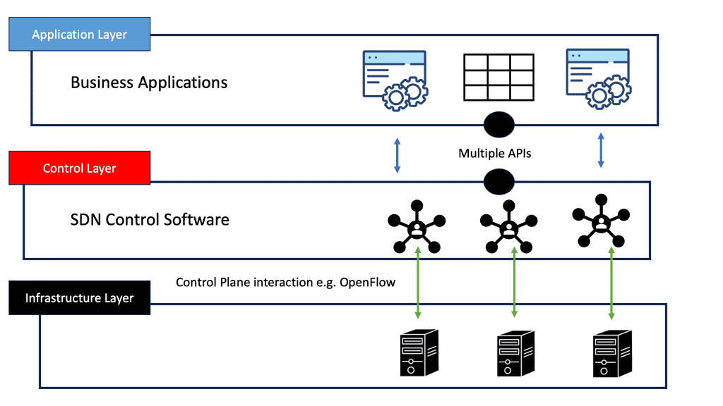
Technological advancements have revolutionized data center routing. Techniques such as Anycast routing allow the same IP address to be used by multiple data centers, directing the data to the nearest or most optimal location. Additionally, software-defined networking (SDN) provides dynamic management of routing policies, enabling rapid responses to changing network conditions. These innovations enhance the flexibility and efficiency of data routing, ensuring that the data highway remains smooth and fast.