The Role of Data Centers
An enterprise’s data center houses the computational power, storage, and applications needed to run its operations. All content is sourced or passed through the data center infrastructure in the IT architecture. Performance, resiliency, and scalability must be considered when designing the data center infrastructure.
Furthermore, the data center design should be flexible so that new services can be deployed and supported quickly. The many considerations required for such a design are port density, access layer uplink bandwidth, actual server capacity, and oversubscription.
A few short years ago, data centers were very different from what they are today. In a multi-cloud environment, virtual networks have replaced physical servers that support applications and workloads across pools of physical infrastructure. Nowadays, data exists across multiple data centers, the edge, and public and private clouds.
Communication between these locations must be possible in the on-premises and cloud data centers. Public clouds are also collections of data centers. In the cloud, applications use the cloud provider’s data center resources.
Redundant data centers
Redundant data centers are essentially two or more in different physical locations. This enables organizations to move their applications and data to another data center if they experience an outage. This also allows for load balancing and scalability, ensuring the organization’s services remain available.
Redundant data centers are generally located in geographically dispersed locations. This ensures that if one of the data centers experiences an issue, the other can take over, thus minimizing downtime. These data centers should also be connected via a high-speed network connection, such as a dedicated line or virtual private network, to allow seamless data transfers between the locations.
Implementing redundant data center BGP involves several crucial steps.
– Firstly, establishing a robust network architecture with multiple data centers interconnected via high-speed links is essential.
– Secondly, configuring BGP routers in each data center to exchange routing information and maintain consistent network topologies is crucial. Additionally, techniques such as Anycast IP addressing and route reflectors further enhance redundancy and fault tolerance.
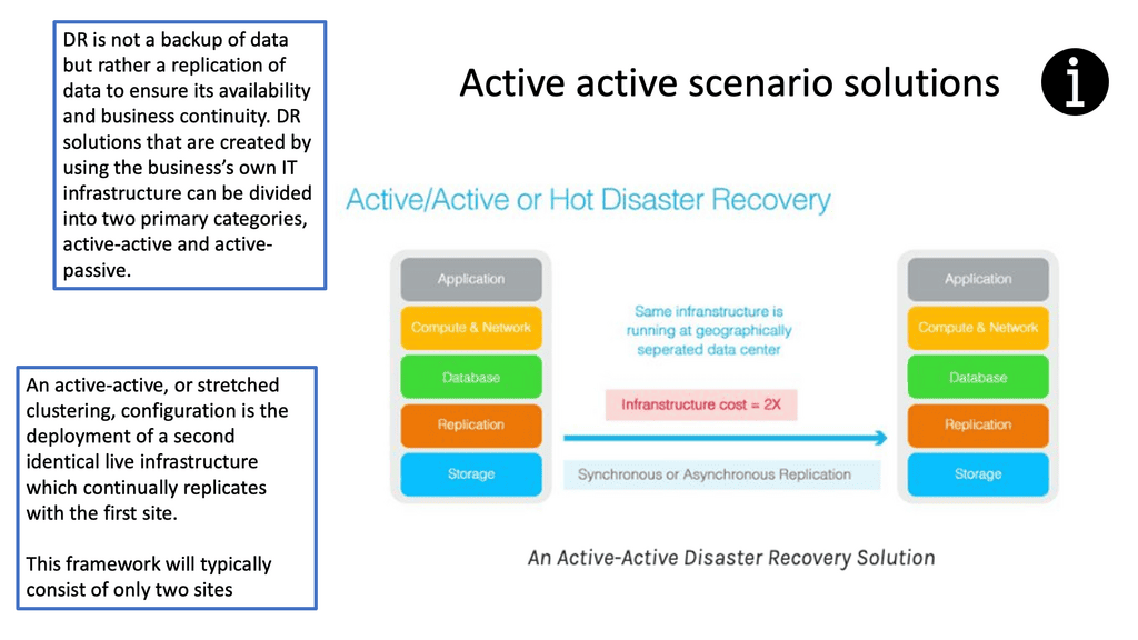
**Benefits of Active-Active Data Center Design**
1. Enhanced Redundancy: With active-active design, organizations can achieve higher levels of redundancy by distributing the workload across multiple data centers. This redundancy ensures that even if one data center experiences a failure or maintenance downtime, the other data center seamlessly takes over, minimizing the impact on business operations.
2. Improved Performance and Scalability: Active-active design enables organizations to scale their infrastructure horizontally by distributing the load across multiple data centers. This approach ensures that the workload is evenly distributed, preventing any single data center from becoming a performance bottleneck. It also allows businesses to accommodate increasing demands without compromising performance or user experience.
3. Reduced Downtime: The active-active design significantly reduces the risk of downtime compared to traditional architectures. In the event of a failure, the workload can be immediately shifted to the remaining active data center, ensuring continuous availability of critical services. This approach minimizes the impact on end-users and helps organizations maintain their reputation for reliability.
4. Disaster Recovery Capabilities: Active-active data center design provides a robust disaster recovery solution. Organizations can ensure that their critical systems and applications remain operational despite a catastrophic failure at one location by having multiple geographically distributed data centers. This design approach minimizes the risk of data loss and provides a seamless failover mechanism.
**Implementation Considerations:**
Implementing an active-active data center design requires careful planning and consideration of various factors. Here are some key considerations:
1. Network Design: A robust and resilient network infrastructure is crucial for active-active data center design. Implementing load balancers, redundant network links, and dynamic routing protocols can help ensure seamless failover and optimal traffic distribution.
2. Data Synchronization: Organizations need to implement effective data synchronization mechanisms to maintain data consistency across multiple data centers. This may involve deploying real-time replication, distributed databases, or file synchronization protocols.
3. Application Design: Applications must be designed to be aware of the active-active architecture. They should be able to distribute the workload across multiple data centers and seamlessly switch between them in case of failure. Application-level load balancing and session management become critical in this context.
Active-active data center design offers organizations a robust solution for high availability and fault tolerance. Businesses can ensure uninterrupted access to critical systems and applications by distributing the workload across multiple data centers. The enhanced redundancy, improved performance, reduced downtime, and disaster recovery capabilities make active-active design an ideal choice for organizations striving to provide seamless and reliable services in today’s digital landscape.
Network Connectivity Center
### What is Google’s Network Connectivity Center?
Google Network Connectivity Center (NCC) is a centralized platform that enables enterprises to manage their global network connectivity. It integrates with Google Cloud’s global infrastructure, offering a unified interface to monitor, configure, and optimize network connections. Whether you are dealing with on-premises data centers, remote offices, or multi-cloud environments, NCC provides a streamlined approach to network management.

### Key Features of NCC
Google’s NCC is packed with features that make it an indispensable tool for network administrators. Here are some key highlights:
– **Centralized Management**: NCC offers a single pane of glass for monitoring and managing all network connections, reducing complexity and improving efficiency.
– **Scalability**: Built on Google Cloud’s robust infrastructure, NCC can scale effortlessly to accommodate growing network demands.
– **Automation and Intelligence**: With built-in automation and intelligent insights, NCC helps in proactive network management, minimizing downtime and optimizing performance.
– **Integration**: Seamlessly integrates with other Google Cloud services and third-party tools, providing a cohesive ecosystem for network operations.


Understanding Network Tiers
Network tiers refer to the different levels of performance and cost offered by cloud service providers. They allow businesses to choose the most suitable network option based on their specific needs. Google Cloud offers two network tiers: Standard and Premium.
The Standard Tier provides businesses with a cost-effective network solution that meets their basic requirements. It offers reliable performance and ensures connectivity within Google Cloud services. With its lower costs, the Standard Tier is an excellent choice for businesses with moderate network demands.
For businesses that demand higher levels of performance and reliability, the Premium Tier is the way to go. This tier offers optimized routes, reduced latency, and enhanced global connectivity. With its advanced features, the Premium Tier ensures optimal network performance for mission-critical applications and services.


Understanding VPC Networking
VPC networking is the backbone of a cloud infrastructure, providing a private and secure environment for your resources. In Google Cloud, a VPC network can be thought of as your own virtual data center in the cloud. It allows you to define IP ranges, subnets, and firewall rules, empowering you with complete control over your network architecture.

Google Cloud’s VPC networking offers a plethora of features that enhance network management and security. From custom IP address ranges to subnet creation and route configuration, you have the flexibility to design your network infrastructure according to your specific needs. Additionally, VPC peering and VPN connectivity options enable seamless communication with other networks, both within and outside of Google Cloud.

 Understanding VPC Peering
VPC Peering enables you to connect VPC networks across projects or organizations. It allows for secure communication and seamless access to resources between peered networks. By leveraging VPC Peering, you can create a virtual network fabric across various environments.

VPC Peering offers several advantages. First, it simplifies network architecture by eliminating the need for complex VPN setups or public IP addresses. Second, it provides low-latency and high-bandwidth connections between VPC networks, ensuring fast and reliable data transfer. Third, it lets you share resources across peering networks, such as databases or storage, promoting collaboration and resource optimization.

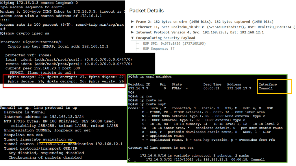
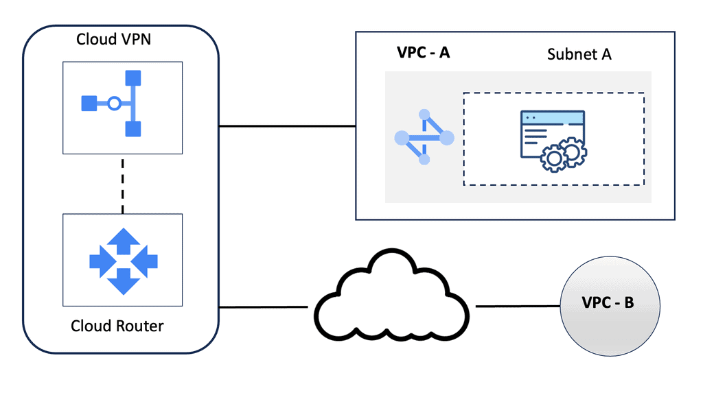
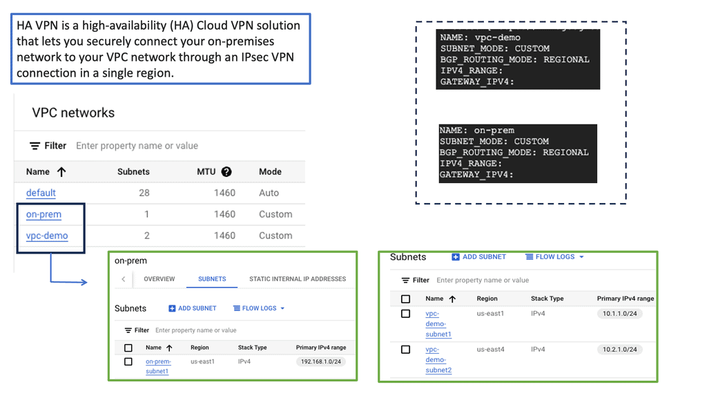
Understanding HA VPN
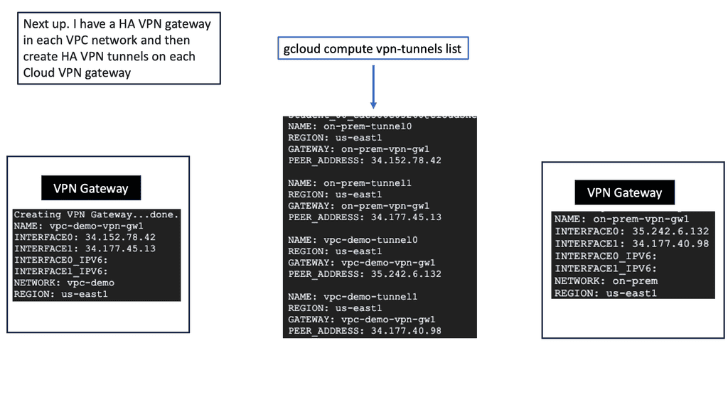
HA VPN, short for High Availability Virtual Private Network, is a feature provided by Google Cloud that ensures continuous and reliable connectivity between your on-premises network and your Google Cloud Virtual Private Cloud (VPC) network. It is designed to minimize downtime and provide fault tolerance by establishing redundant VPN tunnels.
To set up HA VPN, follow a few simple steps. First, ensure that you have a supported on-premises VPN gateway. Then, configure the necessary settings to create a VPN gateway in your VPC network. Next, configure the on-premises VPN gateway to establish a connection with the HA VPN gateway. Finally, validate the connectivity and ensure all traffic is routed securely through the VPN tunnels.
Implementing HA VPN offers several benefits for your network infrastructure. First, it enhances reliability by providing automatic failover in case of VPN tunnel or gateway failures, ensuring uninterrupted connectivity for your critical workloads. Second, HA VPN reduces the risk of downtime by offering a highly available and redundant connection. Third, it simplifies network management by centralizing the configuration and monitoring of VPN connections.
 On-premises Data Centers
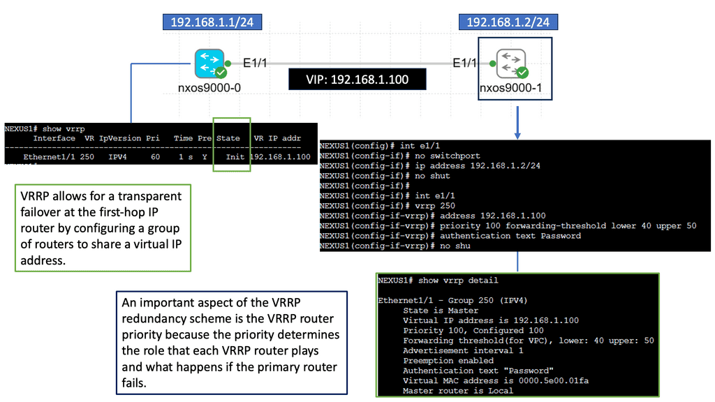
Understanding Nexus 9000 Series VRRP
Nexus 9000 Series VRRP is a protocol that allows multiple routers to work together as a virtual router, providing redundancy and seamless failover in the event of a failure. These routers ensure continuous network connectivity by sharing a virtual IP address, improving network reliability.
With Nexus 9000 Series VRRP, organizations can achieve enhanced network availability and minimize downtime. Utilizing multiple routers can eliminate single points of failure and maintain uninterrupted connectivity. This is particularly crucial in data center environments, where downtime can lead to significant financial losses and reputational damage.
Configuring Nexus 9000 Series VRRP involves several steps. First, a virtual IP address must be defined and assigned to the VRRP group. Next, routers participating in VRRP must be configured with their respective priority levels and advertisement intervals. Additionally, tracking mechanisms can monitor the availability of specific network interfaces and adjust the VRRP priority dynamically.
High Availability and BGP
High availability refers to the ability of a system or network to remain operational and accessible even during failures or disruptions. BGP is pivotal in achieving high availability by employing various mechanisms and techniques.
BGP Multipath is a feature that allows for the simultaneous use of multiple paths to reach a destination. BGP can use various paths to ensure redundancy, load balancing, and enhanced network availability.
BGP Route Reflectors are used in large-scale networks to alleviate the full-mesh requirement between BGP peers. By simplifying the BGP peering configuration, route reflectors enhance scalability and fault tolerance, contributing to high availability.
BGP Anycast is a technique that enables multiple servers or routers to share the same IP address. This method routes traffic to the nearest or least congested node, improving response times and fault tolerance.
Understanding BGP Route Reflection
BGP route reflection is used in large-scale networks to reduce the number of full-mesh peerings required in a BGP network. It allows a BGP speaker to reflect routes received from one set of peers to another set of peers, eliminating the need for every peer to establish a direct connection with every other peer. Using route reflection, network administrators can simplify their network topology and improve its scalability.
The network must be divided into two main components to implement BGP route reflection: route reflectors and clients. Route reflectors serve as the central point for route reflection, while clients are the BGP speakers who establish peering sessions with the route reflectors. It is essential to carefully plan the placement of route reflectors to ensure optimal routing and redundancy in the network.
Route Reflector Hierarchy and Scaling
In large-scale networks, a hierarchy of route reflectors can be implemented to enhance scalability further. This involves using multiple route reflectors, where higher-level route reflectors reflect routes received from lower-level route reflectors. This hierarchical approach distributes the route reflection load and reduces the number of peering sessions required for each BGP speaker, thus improving scalability even further.


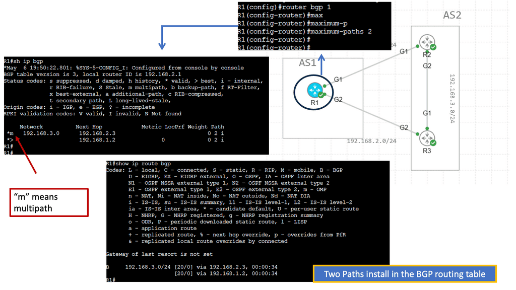
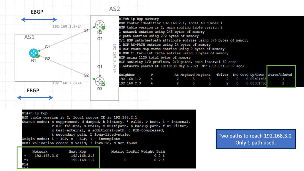
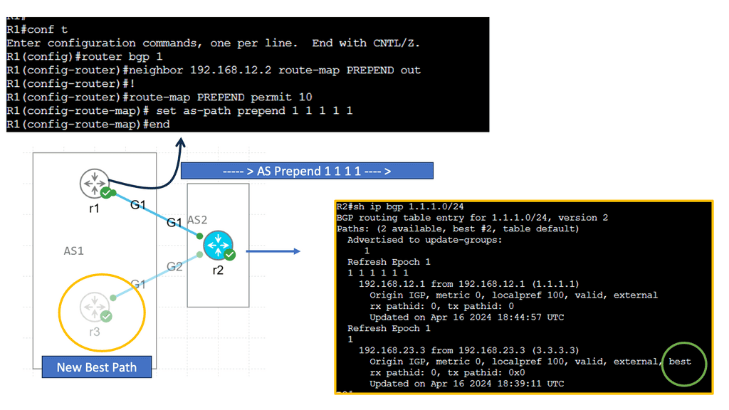
Understanding BGP Multipath
BGP multipath enables the selection and utilization of multiple equal-cost paths for forwarding traffic. Traditionally, BGP would only utilize a single best path, resulting in suboptimal network utilization. With multipath, network administrators can maximize link utilization, reduce congestion, and achieve load balancing across multiple paths.
One of the primary advantages of BGP multipath is enhanced network resilience. By utilizing multiple paths, networks become more fault-tolerant, as traffic can be rerouted in the event of link failures or congestion. Additionally, multipath can improve overall network performance by distributing traffic evenly across available paths, preventing bottlenecks, and ensuring efficient resource utilization.
Expansion and scalability
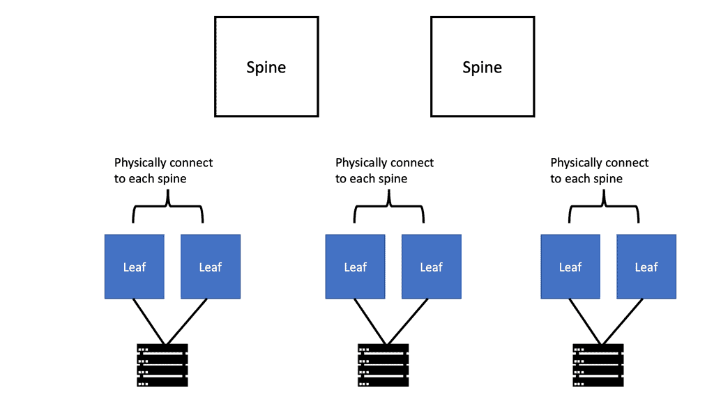
Expanding capacity is straightforward if a link is oversubscribed (more traffic than can be aggregated on the active link simultaneously). Expanding every leaf switch’s uplinks is possible, adding interlayer bandwidth and reducing oversubscription by adding a second spine switch. New leaf switches can be added by connecting them to every spine switch and configuring them as network switches if device port capacity becomes a concern. Scaling the network is made more accessible through ease of expansion. A nonblocking architecture can be achieved without oversubscription between the lower-tier switches and their uplinks.
Defining an active-active data center strategy isn’t easy when you talk to network, server, and compute teams that don’t usually collaborate when planning their infrastructure. An active-active Data center design requires a cohesive technology stack from end to end. Establishing the idea usually requires an enterprise-level architecture drive. In addition, it enables the availability and traffic load sharing of applications across DCs with the following use cases.
- Business continuity
- Mobility and load sharing
- Consistent policy and fast provisioning capability across
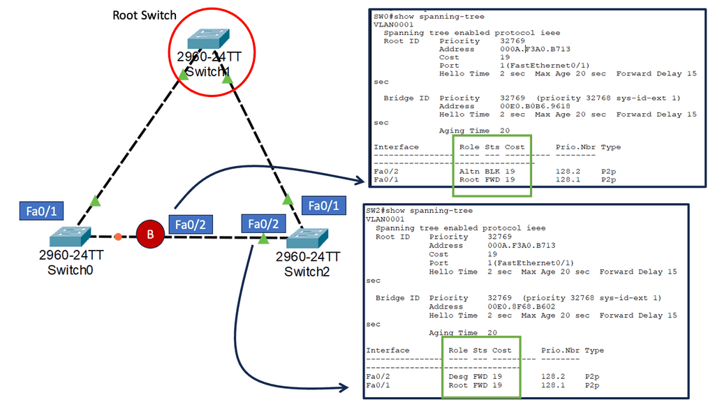
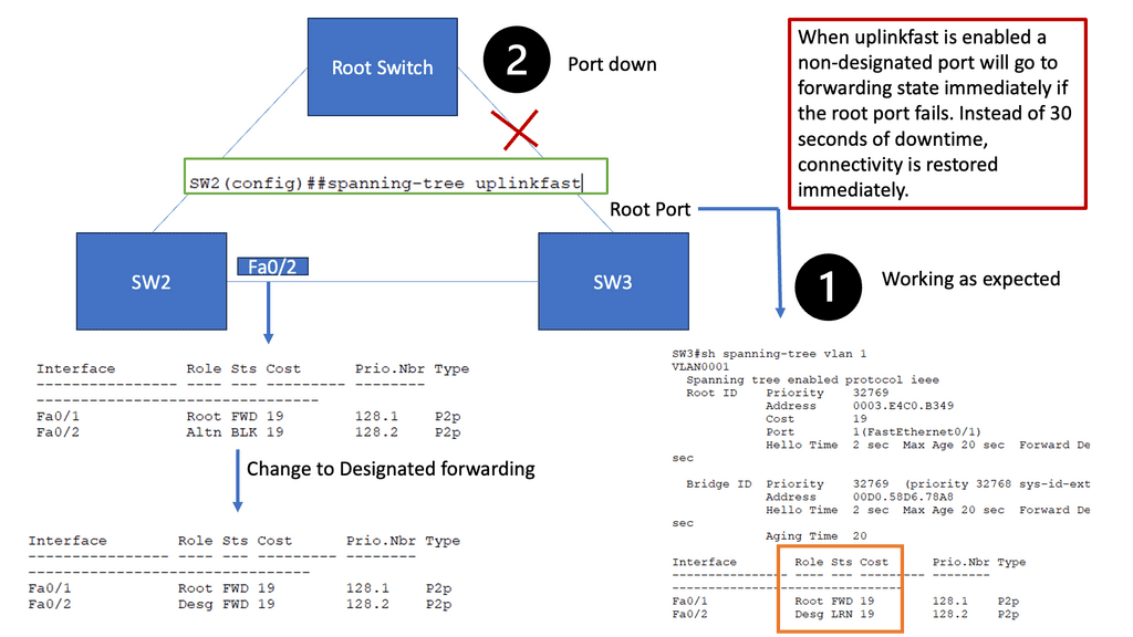
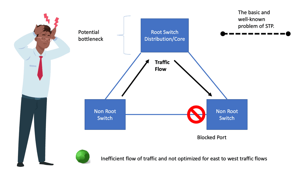
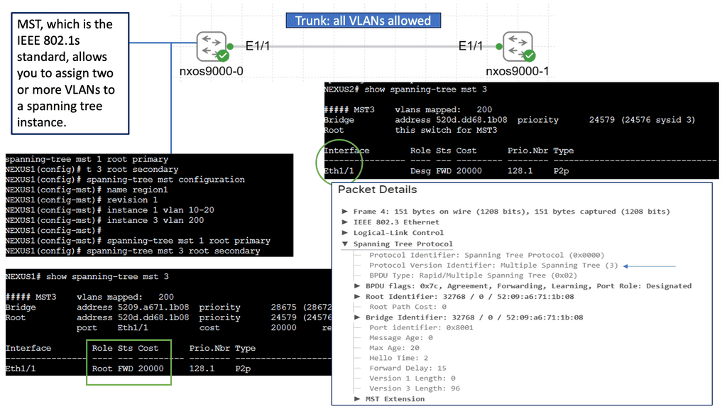
Understanding Spanning Tree Protocol (STP)
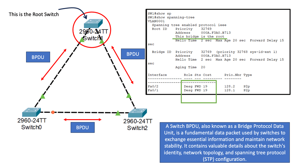
Spanning Tree Protocol (STP) is a fundamental mechanism to prevent loops in Ethernet networks. It ensures that only one active path exists between two network devices, preventing broadcast storms and data collisions. STP achieves this by creating a loop-free logical topology known as the spanning tree. But what about MST? Let’s find out.
As networks grow and become more complex, a single spanning tree may not be sufficient to handle the increasing traffic demands. This is where Spanning Tree MST comes into play. MST allows us to divide the network into multiple logical instances, each with its spanning tree. By doing so, we can distribute the traffic load more efficiently, achieving better performance and redundancy.
MST operates by grouping VLANs into multiple instances, known as regions. Each region has its spanning tree, allowing for independent configuration and optimization. MST relies on the concept of a Root Bridge, which acts as the central point for each instance. By assigning different VLANs to separate cases, we can control traffic flow and minimize the impact of network changes.
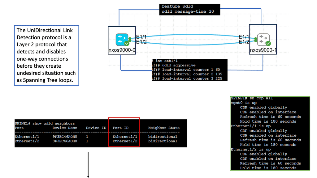
Example: Understanding UDLD
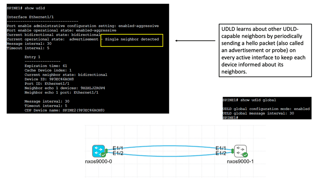
UDLD is a layer 2 protocol designed to detect and mitigate unidirectional links in a network. It operates by exchanging protocol packets between neighboring devices to verify the bidirectional nature of a link. UDLD prevents one-way communication and potential network disruptions by ensuring traffic flows in both directions.
UDLD helps maintain network reliability by identifying and addressing unidirectional links promptly. It allows network administrators to proactively detect and resolve potential issues before they can impact network performance. This proactive approach minimizes downtime and improves overall network availability.
Attackers can exploit unidirectional links to gain unauthorized access or launch malicious activities. UDLD acts as a security measure by ensuring bidirectional communication, making it harder for adversaries to manipulate network traffic or inject harmful packets. By safeguarding against such threats, UDLD strengthens the network’s security posture.
Understanding Port Channel
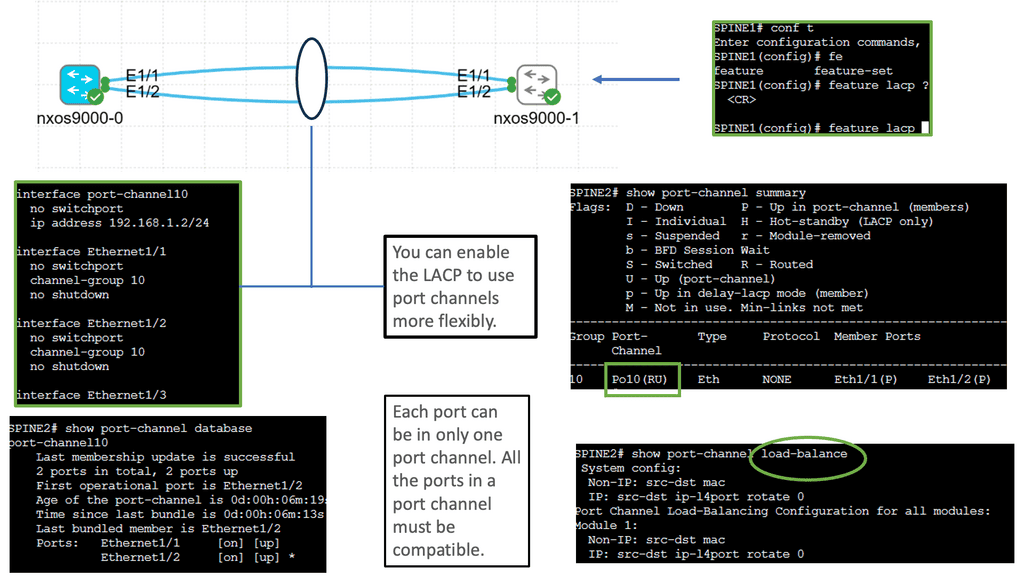
Port Channel, also known as Link Aggregation, is a mechanism that allows multiple physical links to be combined into a single logical interface. This logical interface provides higher bandwidth, improved redundancy, and load-balancing capabilities. Cisco Nexus 9000 Port Channel takes this concept to the next level, offering enhanced performance and flexibility.
a. Increased Bandwidth: By aggregating multiple physical links, the Cisco Nexus 9000 Port Channel significantly increases the available bandwidth, allowing for higher data throughput and improved network performance.
b. Redundancy and High Availability: Port Channel provides built-in redundancy, ensuring network resilience during link failures. With Cisco Nexus 9000, link-level redundancy is seamlessly achieved, minimizing downtime and maximizing network availability.
c. Load Balancing: Cisco Nexus 9000 Port Channel employs intelligent load balancing algorithms that distribute traffic across the aggregated links, optimizing network utilization and preventing bottlenecks.
d. Simplified Network Management: Cisco Nexus 9000 Port Channel simplifies network management by treating multiple links as a logical interface. This streamlines configuration, monitoring, and troubleshooting processes, leading to increased operational efficiency.
Understanding Virtual Port Channel (VPC)
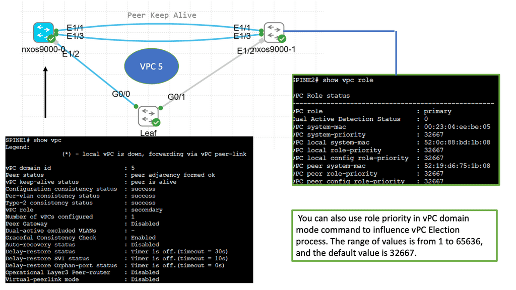
VPC is a link aggregation technique that treats multiple physical links between two switches as a single logical link. This technology enables enhanced scalability, improved resiliency, and efficient utilization of network resources. By combining the bandwidth of multiple links, VPC provides higher throughput and creates a loop-free topology that eliminates the need for Spanning Tree Protocol (STP).
Implementing VPC brings several advantages to network administrators.
First, it enhances redundancy by providing seamless failover in case of link or switch failures.
Second, active-active multi-homing is achieved, ensuring traffic is evenly distributed across all available links.
Third, VPC simplifies network management by treating two switches as single entities, enabling streamlined configuration and consistent policy enforcement.
Lastly, VPC allows for the creation of large Layer 2 domains, facilitating workload mobility and flexibility.

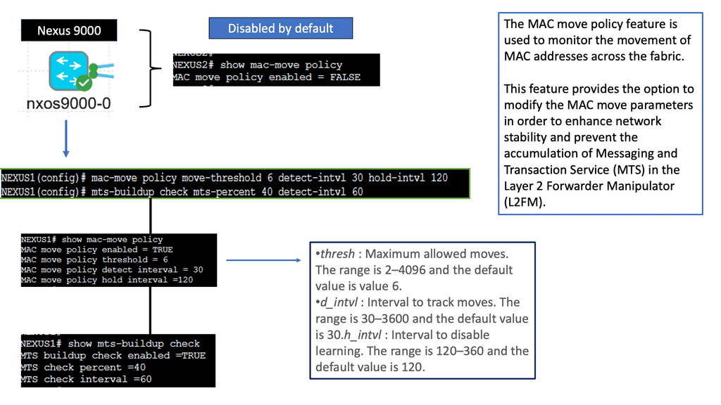
Understanding Nexus Switch Profiles
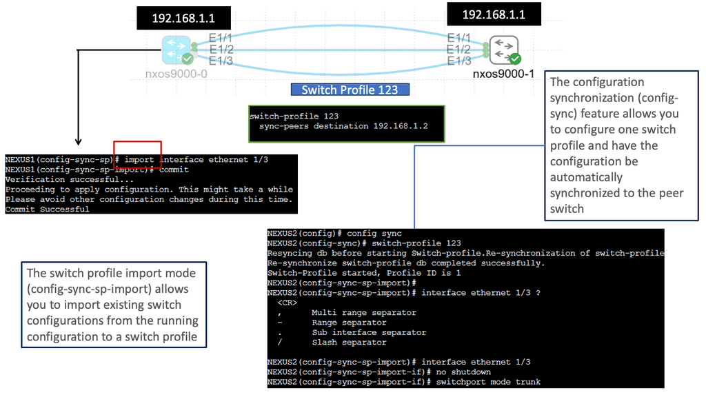
Nexus Switch Profiles are a feature of Cisco’s Nexus switches that enable administrators to define and manage a group of switch configurations as a single entity. This simplifies the management of complex networks by reducing manual configuration tasks and ensuring consistent settings across multiple switches. By encapsulating configurations into profiles, network administrators can achieve greater efficiency and operational agility.
Implementing Nexus Switch Profiles offers a plethora of benefits for network management. Firstly, it enables rapid deployment of new switches with pre-defined configurations, reducing time and effort. Secondly, profiles ensure consistency across the network, minimizing configuration errors and improving overall reliability. Additionally, profiles facilitate streamlined updates and changes, as modifications made to a profile are automatically applied to associated switches. This results in enhanced network security, reduced downtime, and simplified troubleshooting.
A. Active-active Transport Technologies
Transport technologies interconnect data centers. As part of the transport domain, redundancies and links are provided across the site to ensure HA and resiliency. Redundancy may be provided for multiplexers, GPONs, DCI network devices, dark fibers, diversity POPs for surviving POP failure, and 1+1 protection schemes for devices, cards, and links.
In addition, the following list contains the primary considerations to consider when designing a data center interconnection solution.
- Recovery from various types of failure scenarios: Link failures, module failures, node failures, etc.
- Traffic round-trip requirements between DCs based on link latency and applications
- Requirements for bandwidth and scalability
B. Active-Active Network Services
Network services connect all devices in data centers through traffic switching and routing functions. Applications should be able to forward traffic and share load without disruptions on the network. Network services also provide pervasive gateways, L2 extensions, and ingress and egress path optimization across the data centers. Most major network vendors’ SDN solutions also integrate VxLAN overlay solutions to achieve L2 extension, path optimization, and gateway mobility.
Designing active-active network services requires consideration of the following factors:
- Recovery from various failure scenarios, such as links, modules, and network devices, is possible.
- Availability of the gateway locally as well as across the DC infrastructure
- Using a VLAN or VxLAN between two DCs to extend the L2 domain
- Policies are consistent across on-premises and cloud infrastructure – including naming, segmentation rules for integrating various L4/L7 services, hypervisor integration, etc.
- Optimizing path ingresses and regresses.
- Centralized management includes inventory management, troubleshooting, AAA capabilities, backup and restore traffic flow analysis, and capacity dashboards.
C. Active-Active L4-L7 Services
ADC and security devices must be placed in both DCs before active-active L4-L7 services can be built. The major solutions in this space include global traffic managers, application policy controllers, load balancers, and firewalls. Furthermore, these must be deployed at different tiers for perimeter, extranet, WAN, core server farm, and UAT segments. Also, it should be noted that most of the leading L4-L7 service vendors currently offer clustering solutions for their products across the DCs. As a result of clustering, its members can share L4/L7 policies, traffic loads, and failover seamlessly in case of an issue.
Below are some significant considerations related to L4-L7 service design
- Various failure scenarios can be recovered, including link, module, and L4-L7 device failure.
- In addition to naming policies, L4-L7 rules for various traffic types must be consistent across the on-premises infrastructure and in the multiple clouds.
- Network management centralized (e.g., inventory, troubleshooting, AAA capabilities, backups, traffic flow analysis, capacity dashboards, etc.)
D. Active-Active Storage Services
Active-active data centers rely on storage and networking solutions. They refer to the storage in both DCs that serve applications. Similarly, the design should allow for uninterrupted read and write operations. Therefore, real-time data mirroring and seamless failover capabilities across DCs are also necessary. The following are some significant factors to consider when designing a storage system.
- Recover from single-disk failures, storage array failures, and split-brain failures.
- Asynchronous vs. synchronous replication: With synchronized replication, data is simultaneously written for primary storage and replica. It typically requires dedicated FC links, which consume more bandwidth.
- High availability and redundancy of storage: Storage replication factors and the number of disks available for redundancy
- Failure scenarios of storage networks: Links, modules, and network devices
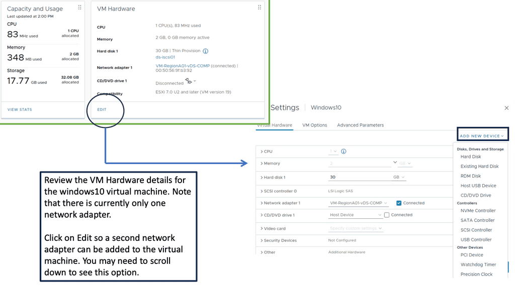
E. Active-Active Server Virtualization
Over the years, server virtualization has evolved. Microservices and containers are becoming increasingly popular among organizations. The primary consideration here is to extend hypervisor/container clusters across the DCs to achieve seamless virtual machine/ container instance movement and fail-over. VMware Docker and Microsoft are the two dominant players in this market. Other examples include KVM, Kubernetes (container management), etc.
Here are some key considerations when it comes to virtualizing servers
- Creating a cross-DC virtual host cluster using a virtualization platform
- HA protects the VM in normal operational conditions and creates affinity rules that prefer local hosts.
- Deploying the same service, VMs in two DCs can take over the load in real time when the host machine is unavailable.
- A symmetric configuration with failover resources is provided across the compute node devices and DCs.
- Managing computing resources and hypervisors centrally
F. Active-Active Applications Deployment
The infrastructure needs to be in place for the application to function. Additionally, it is essential to ensure high application availability across DCs. Applications can also fail over and get proximity access to locations. It is necessary to have Web, App, and DB tiers available at both data centers, and if the application fails in one, it should allow fail-over and continuity.
Here are a few key points to consider
- Deploy the Web services on virtual or physical machines (VMs) by using multiple servers to form independent clusters per DC.
- VM or physical machine can be used to deploy App services. If the application supports distributed deployment, multiple servers within the DC can form a cluster or various servers across DCs can create a cluster (preferred IP-based access).
- The databases should be deployed on physical machines to form a cross-DC cluster (active-standby or active-active). For example, Oracle RAC, DB2, SQL with Windows server failover cluster (WSFC)
Knowledge Check: Default Gateway Redundancy
A first-hop redundancy protocol (FHRP) always provides an active default IP gateway. To transparently failover at the first-hop IP router, FHRPs use two or more routers or Layer 3 switches.
The default gateway facilitates network communication. Source hosts send data to their default gateways. Default gateways are IP addresses on routers (or Layer 3 switches) connected to the same subnet as the source hosts. End hosts are usually configured with a single default gateway IP address when the network topology changes. The local device cannot send packets off the local network segment if the default gateway is not reached. There is no dynamic method by which end hosts can determine the address of a new default gateway, even if there is a redundant router that may serve as the default gateway for that segment.
Advanced Topics:
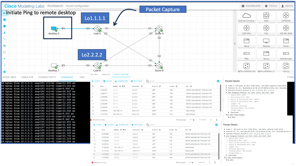
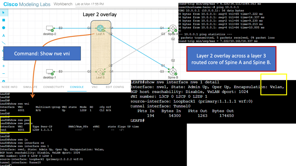
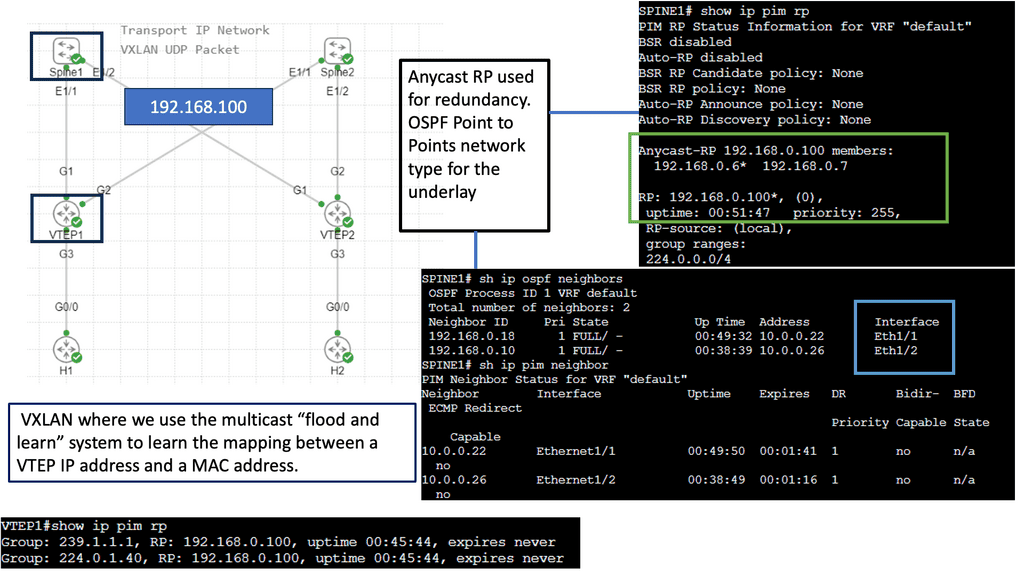
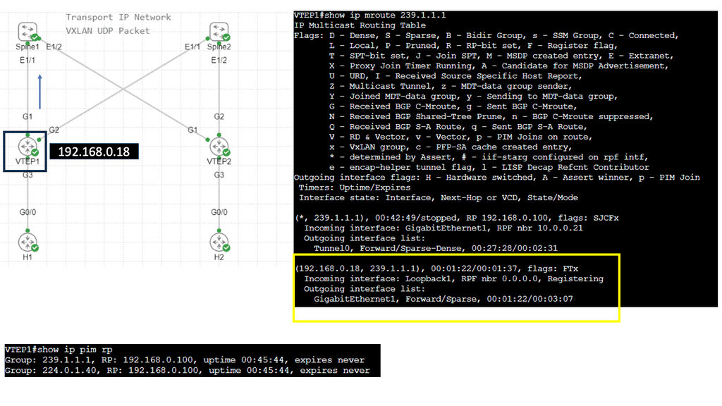
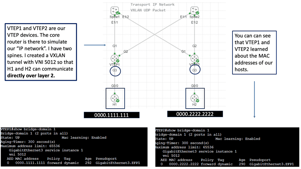
Understanding VXLAN Flood and Learn
The flood and learning process is an essential component of VXLAN networks. It involves flooding broadcast, unknown unicast, and multicast traffic within the VXLAN segment to ensure that all relevant endpoints receive the necessary information. By using multicast, VXLAN optimizes network traffic and reduces unnecessary overhead.
Multicast plays a crucial role in enhancing the efficiency of VXLAN flood and learn. By utilizing multicast groups, the network can intelligently distribute traffic to only those endpoints that require the information. This approach minimizes unnecessary flooding, reduces network congestion, and improves overall performance.
Several components must be in place to enable VXLAN flood and learn with multicast. We will explore the necessary configurations on the VXLAN Tunnel Endpoints (VTEPs) and the underlying multicast infrastructure. Topics covered will include multicast group management, IGMP snooping, and PIM (Protocol Independent Multicast) configuration.

Related: Before you proceed, you may find the following useful:
At its core, an active active data center is based on fault tolerance, redundancy, and scalability principles. This means that the active data center should be designed to withstand any hardware or software failure, have multiple levels of data storage redundancy, and scale up or down as needed.
The data center also provides an additional layer of security. It is designed to protect data from unauthorized access and malicious attacks. It should also be able to detect and respond to any threats quickly and in a coordinated manner.
A comprehensive monitoring and management system is essential to ensure the data center functions correctly. This system should be designed to track the data center’s performance, detect problems, and provide the necessary alerting mechanisms. It should also provide insights into how the data center operates so that any necessary changes can be made.
Cisco Validated Design
Cisco has validated this design, which is freely available on the Cisco site. In summary, they have tested a variety of combinations, such as VSS-VSS, VSS-vPV, and vPC-vPC, and validated the design with 200 Layer 2 VLANs and 100 SVIs or 1000 VLANs and 1000 SVI with static routing.
At the time of writing, the M series for the Nexus 7000 supports native encryption of Ethernet frames through the IEEE 802.1AE standard. This implementation uses Advanced Encryption Standard ( AES ) cipher and a 128-bit shared key.
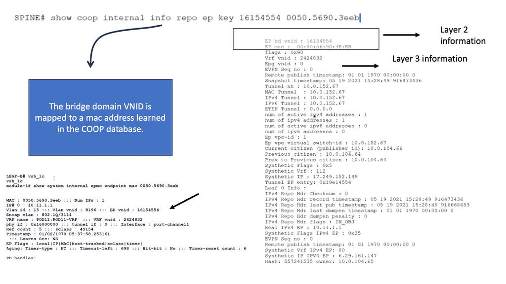
Example: Cisco ACI
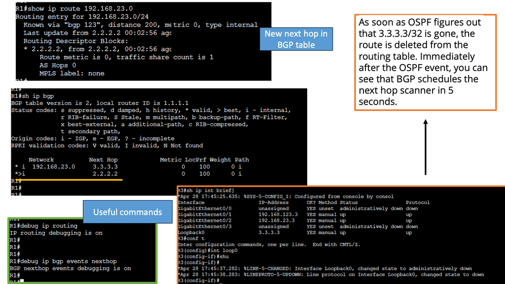
In the following lab guide, we demonstrate Cisco ACI. To extend Cisco ACI, we have different designs, such as multi-site and multi-pod. This type of design overcomes many challenges of raising a data center, which we will discuss in this post, such as extending layer 2 networks.
One crucial value of the Cisco ACI is the COOP database that maps endpoints in the network. The following screenshots show the synchronized COOP database across spines, even in different data centers. Notice that the bridge domain VNID is mapped to the MAC address. The COOP database is unique to the Cisco ACI.
**The Challenge: Layer 2 is Weak**
The challenge of data center design is “Layer 2 is weak & IP is not mobile.” In the past, best practices recommended that networks from distinct data centers be connected through Layer 3 ( routing ), isolating the known Layer 2 turmoil. However, the business is driving the application requirements, changing the connectivity requirements between data centers.
The need for an active data center has been driven by the following. It is generally recommended to have Layer 3 connections with path separation through Multi-VRF, P2P VLANs, or MPLS/VPN, along with a modular building block data center design.
Yet, some applications cannot function over a Layer 3 environment. For example, most geo clusters require Layer 2 adjacency between their nodes, whether for heartbeat and connection ( status and control synchronization ) state information or the requirement to share virtual IP.
MAC addresses to facilitate traffic handling in case of failure. However, some clustering products ( Veritas, Oracle RAC ) support communication over Layer 3 but are a minority and don’t represent the general case.
Defining active data centers
The term active-active refers to using at least two data centers where both can service an application at any time, so each functions as an active application site. The demand for active-active data center architecture is to accomplish seamless workload mobility and enable distributed applications along with the ability to pool and maximize resources.
We must first have active-active data center infrastructure for an active/active application setup. Remember that the network is just one key component of active/active data centers). An active-active DC can be divided into two halves from a pure network perspective:-
- Ingress Traffic – inbound traffic
- Egress Traffic – outbound traffic
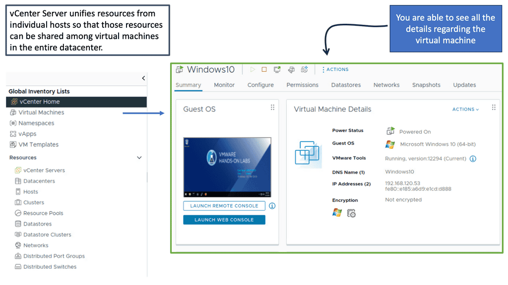
Active Active Data Center and VM Migration
Migrating applications and data to virtual machines (VMs) are becoming increasingly popular as organizations seek to reduce their IT costs and increase the efficiency of their services. VM migration moves existing applications, data, and other components from a physical server to a virtualized environment. This process is becoming increasingly more cost-effective and efficient for organizations, eliminating the need for additional hardware, software, and maintenance costs.
Virtual Machine migration between data centers increases application availability, Layer 2 network adjacency between ESX hosts is currently required, and a consistent LUN must be maintained for stateful migration. In other words, if the VM loses its IP address, it will lose its state, and the TCP sessions will drop, resulting in a cold migration ( VM does a reboot ) instead of a hot migration ( VM does not reboot ).
Due to the stretched VLAN requirement, data center architects started to deploy traditional Layer 2 over the DCI and, unsurprisingly, were faced with exciting results. Although flooding and broadcasts are necessary for IP communication in Ethernet networks, they can become dangerous in a DCI environment.
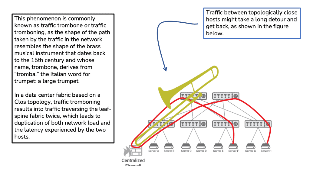
Traffic Tramboning
Traffic tromboning can also be formed between two stretched data centers, so nonoptimal internal routing happens within extended VLANs. Trombones, by their very nature, create a network traffic scalability problem. Addressing this through load balancing among multiple trombones is challenging since their services are often stateful.
Traffic tromboning can affect either ingress or egress traffic. On egress, you can have FHRP filtering to isolate the HSRP partnership and provide an active/active setup for HSRP. On ingress, you can have GSLB, Route Injection, and LISP.
Cisco Active-active data center design and virtualization technologies
Virtualization technologies can overcome many of these problems by being used for Layer 2 extensions between data centers. These include vPC, VSS, Cisco FabricPath, VPLS, OTV, and LISP with its Internet locator design. In summary, different technologies can be used for LAN extensions, and the primary mediums in which they can be deployed are Ethernet, MPLS, and IP.
- Ethernet: VSS and vPC or Fabric Path
- MLS: EoMPLS and A-VPLS and H-VPLS
- IP: OTV
- LISP
Ethernet Extensions and Multi-Chassis EtherChannel ( MEC )
It requires protected DWDM or direct fibers and works only between two data centers. It cannot support multi-datacenter topology, i.e., a full mesh of data centers, but can help hub and spoke topologies.
Previously, LAG could only terminate on one physical switch. VSS-MEC and vPC are port-channeling concepts extending link aggregation to two physical switches. This allows for creating L2 typologies based on link aggregation, eliminating the dependency on STP, thus enabling you to scale available Layer 2 bandwidth by bonding the physical links.
Because vPC and VSS create a single connection from an STP perspective, disjoint STP instances can be deployed in each data center. Such isolation can be achieved with BPDU Filtering on the DCI links or Multiple Spanning Tree ( MST ) regions on each site.
At the time of writing, vPC does not support Layer 3 peering, but if you want an L3 link, create one, as this does not need to run on dark fiber or protected DWDM, unlike the extended Layer 2 links.
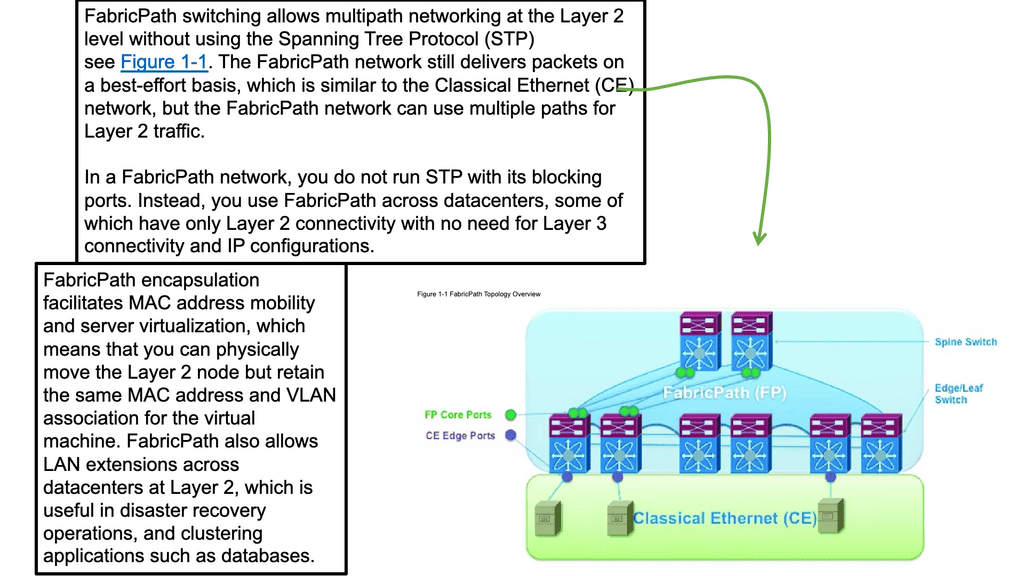
Ethernet Extension and Fabric path
The fabric path allows network operators to design and implement a scalable Layer 2 fabric, allowing VLANs to help reduce the physical constraints on server location. It provides a high-availability design with up to 16 active paths at layer 2, with each path a 16-member port channel for Unicast and Multicast.
This enables the MSDC networks to have flat typologies, separating nodes by a single hop ( equidistant endpoints ). Cisco has not targeted Fabric Path as a primary DCI solution as it does not have specific DCI functions compared to OTV and VPLS.
Its primary purpose is for Clos-based architectures. However, if you need to interconnect three or more sites, the Fabric path is a valid solution when you have short distances between your DCs via high-quality point-to-point optical transmission links.
Your WAN links must support Remote Port Shutdown and microflapping protection. By default, OTV and VPLS should be the first solutions considered as they are Cisco-validated designs with specific DCI features. For example, OTV can flood unknown unicast for particular VLANs.
IP Core with Overlay Transport Virtualization ( OTV ).
OTV provides dynamic encapsulation with multipoint connectivity of up to 10 sites ( NX-OS 5.2 supports 6 sites, and NX-OS 6.2 supports 10 sites ). OTV, also known as Over-The-Top virtualization, is a specific DCI technology that enables Layer 2 extension across data center sites by employing a MAC in IP encapsulation with built-in loop prevention and failure boundary preservation.
There is no data plane learning. Instead, the overlay control plane ( Layer 2 IS-IS ) on the provider’s network facilitates all unicast and multicast learning between sites. OTV has been supported on the Nexus 7000 since the 5.0 NXOS Release and ASR 1000 since the 3.5 XE Release. OTV as a DCI has robust high availability, and most failures can be sub-sec convergence with only extreme and very unlikely failures such as device down resulting in <5 seconds.
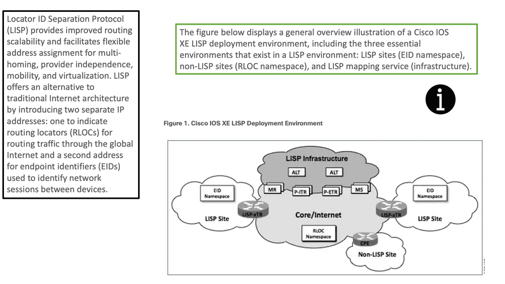
Locator ID/Separator Protocol ( LISP)
Locator ID/Separator Protocol ( LISP) has many applications. As the name suggests, it separates the location and identifier of the network hosts, enabling VMs to move across subnet boundaries while retaining their IP address and enabling advanced triangular routing designs.
LISP works well when you have to move workloads and distribute workloads across data centers, making it a perfect complementary technology for an active-active data center design. It provides you with the following:
- a) Global IP mobility across subnets for disaster recovery and cloud bursting ( without LAN extension ) and optimized routing across extended subnet sites.
- b) Routing with extended subnets for active/active data centers and distributed clusters ( with LAN extension).
LISP answers the problems with ingress and egress traffic tromboning. It has a location mapping table, so when a host move is detected, updates are automatically triggered, and ingress routers (ITRs or PITRs) send traffic to the new location. From an ingress path flow inbound on the WAN perspective, LISP can answer our little problems with BGP in controlling ingress flows. Without LISP, we are limited to specific route filtering, meaning if you have a PI Prefix consisting of a /16.
If you break this up and advertise into 4 x /18, you may still get poor ingress load balancing on your DC WAN links; even if you were to break this up to 8 x /19, the results might still be unfavorable.
LISP works differently than BGP because a LISP proxy provider would advertise this /16 for you ( you don’t advertise the /16 from your DC WAN links ) and send traffic at 50:50 to our DC WAN links. LISP can get a near-perfect 50:50 conversion rate at the DC edge.