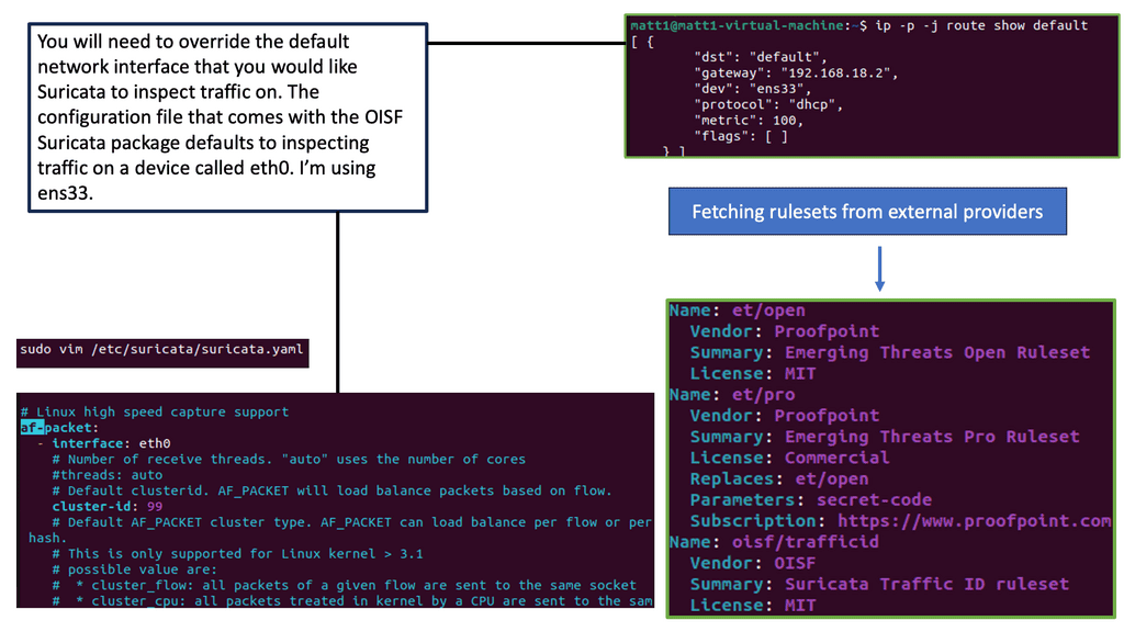
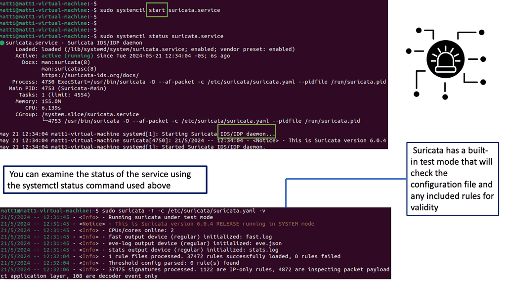
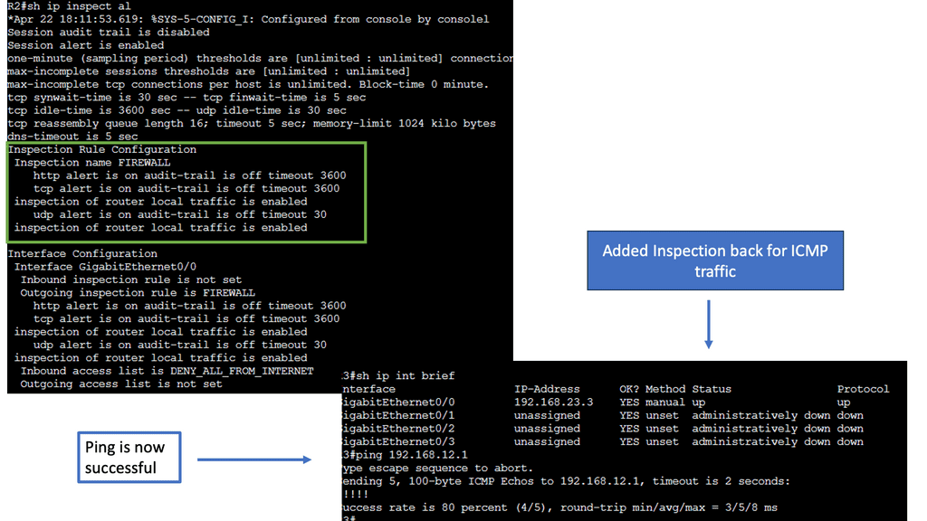
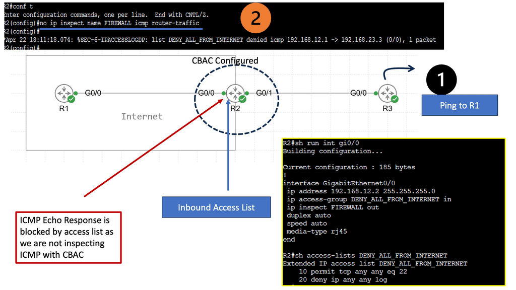
Data Center Network Design
To embark on a successful network design journey, it is essential first to understand the data center’s specific requirements. Factors such as scalability, bandwidth, latency, and reliability need to be carefully assessed. By comprehending the data center’s unique needs, network architects can lay a solid foundation for an optimized design.
Efficiency and resilience are at the core of any well-designed data center network. Building on the requirements identified in the previous section, architects must consider redundancy, load balancing, and fault tolerance principles. The design should minimize single points of failure while maximizing resource utilization and network performance.
Various network topologies and architectures can be employed in data center network design. Each option offers unique advantages and trade-offs, from traditional hierarchical designs to modern approaches like leaf-spine architectures. This section will explore different topologies, highlighting their strengths and considerations.
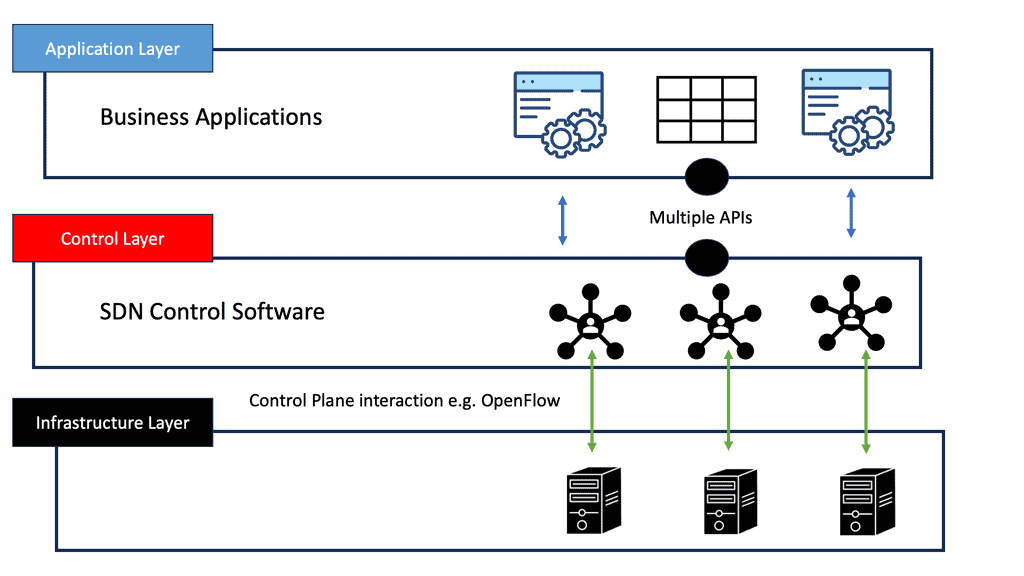
Virtualization and SDN have revolutionized data center network design, offering increased flexibility and agility. By abstracting network functions from physical infrastructure, virtualization allows for dynamic resource allocation and improved scalability. SDN further enhances network programmability, enabling centralized management and automation. This section will delve into the benefits and implementation considerations of these technologies.
Network, security, and computing
– A data center architecture consists of three main components: the data center network, the data center security, and the data center computing architecture. In addition to these three types of architecture, there are also data center physical architectures and data center information architectures. The following are three typical compositions.
– Network architecture for data centers: Data center networks (DCNs) are arrangements of network devices interconnecting data center resources. They are a crucial research area for Internet companies and large cloud computing firms. The design of a data center depends on its network architecture.
– It is common for routers and switches to be arranged in hierarchies of two or three levels. There are three-tier DCNs: fat tree DCNs, DCells, and others. There has always been a focus on scalability, robustness, and reliability regarding data center network architectures.
– Data center security refers to physical practices and virtual technologies for protecting data centers from threats, attacks, and unauthorized access. It can be divided into two components: physical security and software security. A firewall between a data center’s external and internal networks can protect it from attack.
Data Center Network Design Considerations
a. Understanding the Requirements
Before embarking on the design process, it’s crucial to understand the data center’s unique requirements. Factors such as power and cooling, network connectivity, scalability, and security are vital in determining the design approach. By thoroughly assessing these requirements, architects can create a blueprint that aligns with the organization’s current and future needs.
b. Optimizing Physical Layout
The physical layout of a data center significantly impacts its efficiency and performance. This section will delve into rack placement, aisle design, cable management, and airflow optimization. By adopting best practices in physical layout design, data center operators can minimize energy consumption, reduce maintenance costs, and enhance overall operational efficiency.
c. Redundancy and Resilience
Data centers demand high levels of redundancy and resilience to ensure uninterrupted operations. This section will explore the concept of redundancy in power and cooling systems, backup generators, redundant network connectivity, and failover mechanisms. Implementing robust redundancy measures helps mitigate the risk of downtime and ensures continuous availability of critical services.
4. Security and Compliance
Data centers store sensitive and valuable information, making security a top priority. This section will discuss the importance of physical security measures, access controls, surveillance systems, and fire suppression mechanisms. Additionally, we will explore compliance standards and regulations that govern data center operations, such as SOC 2, ISO 27001, and GDPR.
5. Embracing Green Initiatives
As environmental sustainability gains importance, data centers seek ways to minimize their carbon footprint. This section will focus on energy-efficient design practices, including using renewable energy sources, efficient cooling techniques, and server virtualization. Data centers can contribute to a more sustainable future by adopting green initiatives.
Data Center Network Security
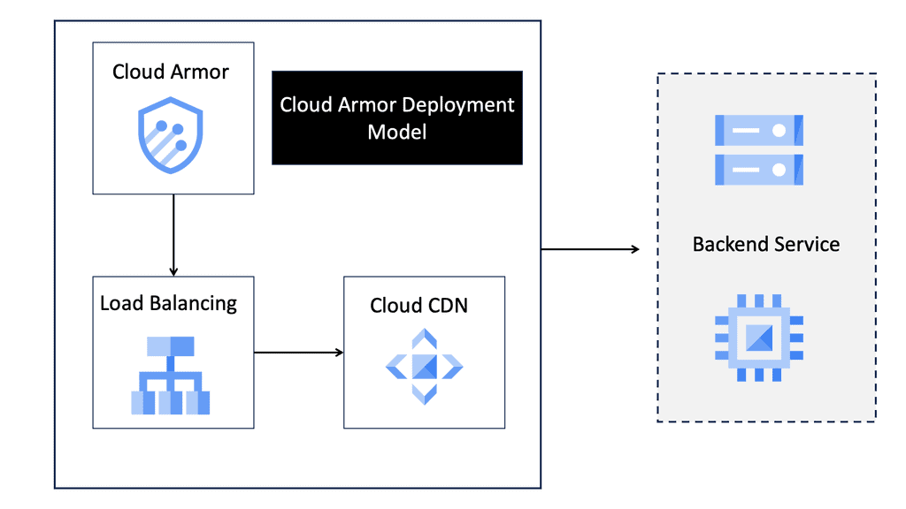
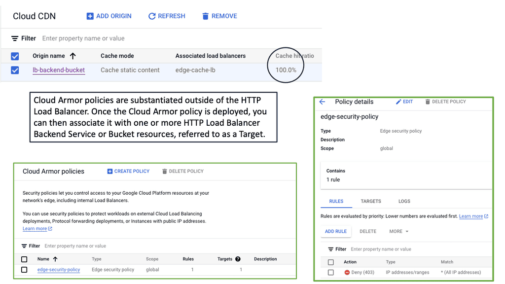
### What is Cloud Armor?
Cloud Armor is a security service offered by Google Cloud that provides protection against distributed denial-of-service (DDoS) attacks and other web-based threats. It leverages Google’s global infrastructure to offer scalable and reliable protection, ensuring that your applications and services remain available and secure even in the face of large-scale attacks.
### Key Features of Cloud Armor
Cloud Armor comes packed with several features that make it an indispensable tool for modern enterprises. Some of its key features include:
– **DDoS Protection:** Automatically detects and mitigates DDoS attacks, ensuring minimal disruption to your services.
– **Web Application Firewall (WAF):** Provides customizable rules to block malicious traffic and protect against common web vulnerabilities.
– **Edge Security Policies:** Allows you to define security policies at the edge of your network, ensuring threats are mitigated before they reach your core infrastructure.
– **Adaptive Protection:** Uses machine learning to identify and respond to evolving threats in real-time.
### Understanding Edge Security Policies
One of the standout features of Cloud Armor is its ability to implement edge security policies. These policies enable organizations to enforce security measures at the periphery of their network, providing an additional layer of defense. By stopping threats at the edge, you can prevent them from penetrating deeper into your network, thereby reducing the risk of data breaches and other security incidents.
Edge security policies can be tailored to your specific needs, allowing you to block traffic based on various criteria such as IP address, geographic location, and request patterns. This granular control helps you enforce stringent security measures while maintaining the performance and availability of your services.
### Benefits of Using Cloud Armor
Deploying Cloud Armor offers several benefits that can significantly enhance your security posture. These include:
– **Scalability:** Designed to handle traffic spikes and large-scale attacks, ensuring your services remain available even under heavy load.
– **Customization:** Flexible rules and policies allow you to tailor security measures to your unique requirements.
– **Proactive Defense:** Real-time threat detection and mitigation keep your applications protected against the latest cyber threats.
– **Cost-Effective:** By leveraging Google’s global infrastructure, you can achieve enterprise-level security without the need for significant upfront investment.
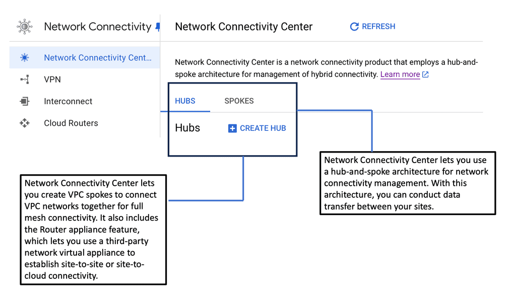
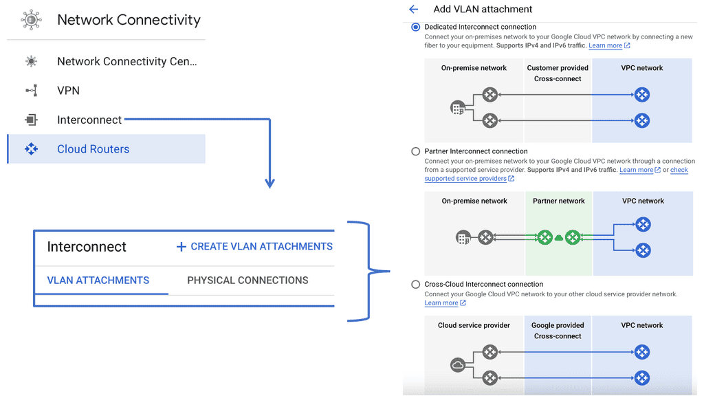
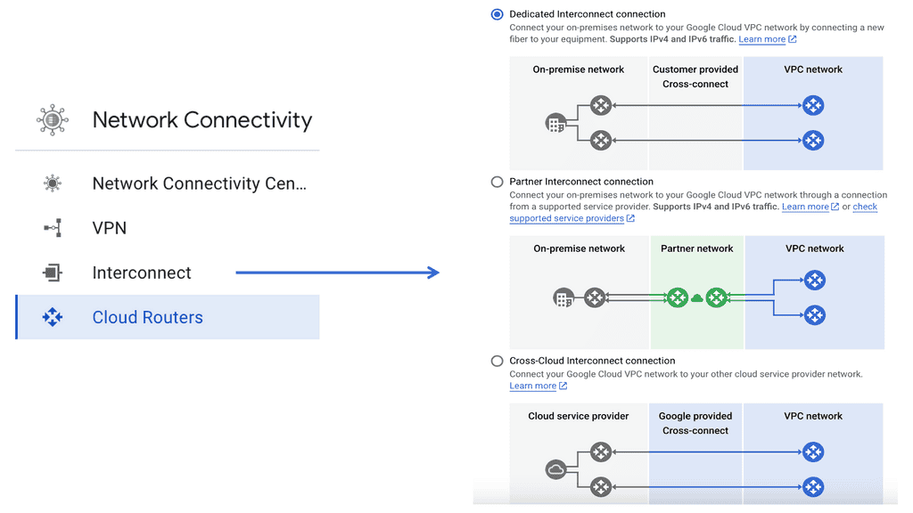
### What is Google Network Connectivity Center?
Google Network Connectivity Center is a unified platform designed to manage and monitor network connections across a variety of environments. Whether you’re dealing with on-premises data centers, cloud environments, or hybrid setups, NCC provides a centralized control point. It simplifies the complexities involved in network management, allowing IT teams to focus on optimizing performance rather than troubleshooting issues.


 ### Key Features of Google NCC
#### Unified Management
NCC offers a single pane of glass for managing network connections, making it easier to oversee and control your entire network infrastructure. This unified management approach reduces the need for multiple tools and interfaces, streamlining operations and increasing efficiency.
#### Flexible Connectivity Options
Google NCC supports a range of connectivity options, including VPNs, interconnects, and peering. This flexibility ensures that you can choose the best connectivity method for your specific needs, whether it’s connecting remote offices or integrating with third-party cloud services.
#### Real-Time Monitoring and Analytics
One of the standout features of NCC is its real-time monitoring and analytics capabilities. With detailed insights into network performance and traffic patterns, you can quickly identify and resolve issues, optimize resource allocation, and ensure consistent network performance.
Understanding Network Tiers
Network tiers are a concept that categorizes network traffic based on its importance and priority. By classifying traffic into different tiers, businesses can allocate resources accordingly and optimize their network usage. In the case of Google Cloud, there are two main network tiers: Premium Tier and Standard Tier.
The Premium Tier is designed to deliver exceptional performance and reliability. It leverages Google’s global network infrastructure, ensuring low latency and high throughput for critical applications. By utilizing the Premium Tier, businesses can enhance user experience, reduce latency-related issues, and improve overall network performance.
While the Premium Tier offers top-tier performance, the Standard Tier provides a cost-effective solution for non-critical workloads. It offers reliable network connectivity at a lower price point, making it an excellent choice for applications that do not require ultra-low latency or high bandwidth. By strategically utilizing the Standard Tier, businesses can optimize their network spend without compromising on reliability.


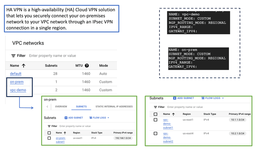
Understanding VPC Networking
VPC, or Virtual Private Cloud, is a virtual network dedicated to a specific Google Cloud project. It allows users to define and manage their network resources, including subnets, IP addresses, and firewall rules. With VPC networking, businesses can create isolated environments and control the flow of traffic within their cloud infrastructure.

Google Cloud’s VPC networking offers a range of powerful features. Firstly, it provides global connectivity, allowing businesses to connect resources across regions seamlessly. Additionally, VPC peering enables secure communication between different VPC networks, facilitating collaboration and data sharing. Moreover, VPC networking offers granular control through firewall rules, ensuring robust security for applications and services.


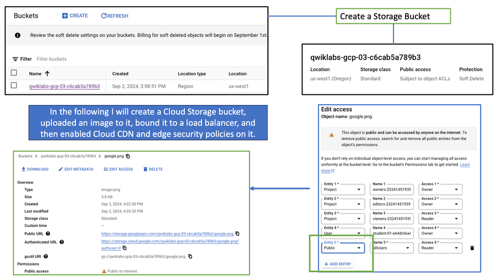
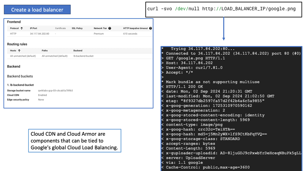
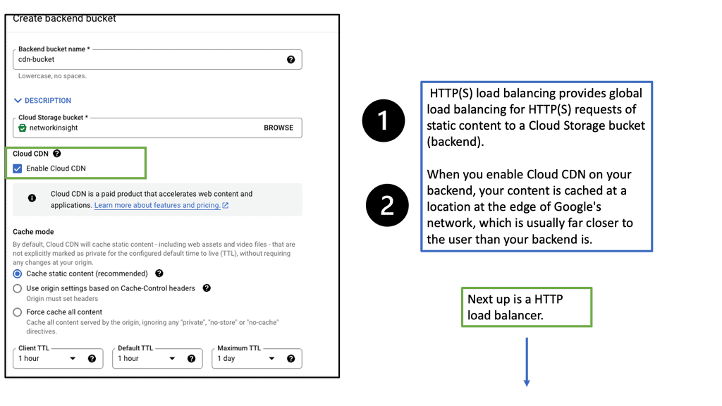
What is Google Cloud CDN?
Google Cloud CDN, short for Content Delivery Network, is a globally distributed network of servers designed to deliver content to users at blazing-fast speed. Cloud CDN minimizes latency and ensures a seamless user experience by caching your content in strategic locations worldwide. Whether it’s static assets, dynamic content, or even streaming media, Cloud CDN optimizes the delivery process, reducing the load on your origin servers and improving overall performance.
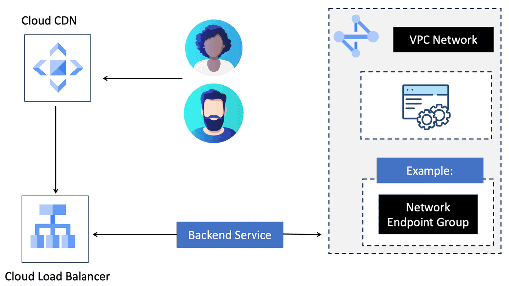
Cloud CDN operates by leveraging Google’s extensive network infrastructure. When a user requests content from your website or application, Cloud CDN intelligently routes the request to the nearest edge location. If the content is already cached at that edge location, it is immediately delivered to the user, eliminating the need for a round trip to the origin server. This not only reduces latency but also saves bandwidth and server resources.
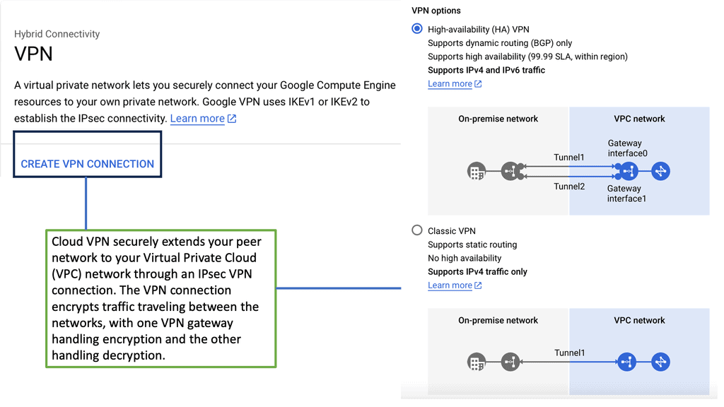
Understanding VPC Network Peering
VPC network peering connects VPC networks from different projects or within the same project within Google Cloud. It enables direct communication between these networks, eliminating the need for complex VPN setups or public IP addresses. This seamless connectivity can significantly enhance collaboration, data sharing, and network management.

Enhanced Security: VPC network peering ensures that communication between peered networks remains isolated from the public internet. This adds an extra layer of security by reducing the exposure to potential cyber threats.
Improved Performance: By leveraging VPC network peering, data can be transferred at incredibly high speeds between peered networks. This enables faster resource access, reduces latency, and enhances overall application performance.
Simplified Network Architecture: VPC network peering allows for a more streamlined and simplified network architecture. Instead of relying on complex gateways or routers, communication between VPCs can be established directly, making network management and troubleshooting more straightforward.

Data Center Network Types
a. The Three-Tier Data Center Network
The three-tier DCN architecture has been a traditional approach in data center networking. It consists of three layers: the access layer, the aggregation layer, and the core layer. Each layer serves a specific purpose, from connecting end devices to aggregating traffic and providing high-speed connectivity. This hierarchical design allows for scalability and redundancy, making it a popular choice for many data centers.
b. Unleashing the Power of Fat Tree Data Center Networks
The fat tree DCN, also known as the Clos network, has gained prominence recently due to its ability to handle large-scale data center deployments. Unlike the three-tier DCN, a fat tree network provides multiple paths between devices, enabling better load balancing and higher bandwidth capacity. Fat tree networks offer low-latency communication and enhanced fault tolerance by utilizing a non-blocking switching fabric, making them ideal for mission-critical applications.
c. Exploring the Revolutionary DCell Approach
The DCell architecture takes a novel approach to data center networking and offers a unique perspective on scalability and fault tolerance. DCell networks are based on a hierarchical structure of cells, where each cell consists of a group of servers connected together. This decentralized design eliminates the need for traditional core switches and enables direct server-to-server communication. With its self-organizing capabilities, DCell networks provide excellent scalability, fault tolerance, and efficient resource utilization.
Composition of Data Center Architecture
Routing and Switching:
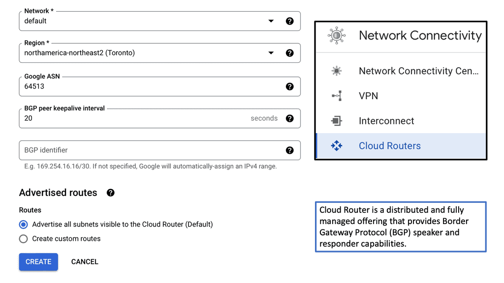
Routing is the backbone of a data center network, guiding data packets through the labyrinthine pathways. It involves determining the optimal path for data to travel from source to destination, considering network congestion, latency, and cost factors. Advanced routing protocols like Border Gateway Protocol (BGP) enable dynamic route selection, ensuring efficient and fault-tolerant data delivery.
Switching complements routing by facilitating efficient data transmission within a local network. At the heart of a data center, switches act as intelligent traffic controllers, directing data packets to their intended destinations. With features like VLANs (Virtual Local Area Networks) and Quality of Service (QoS), switches prioritize and prioritize traffic, optimizing network performance and ensuring seamless communication.
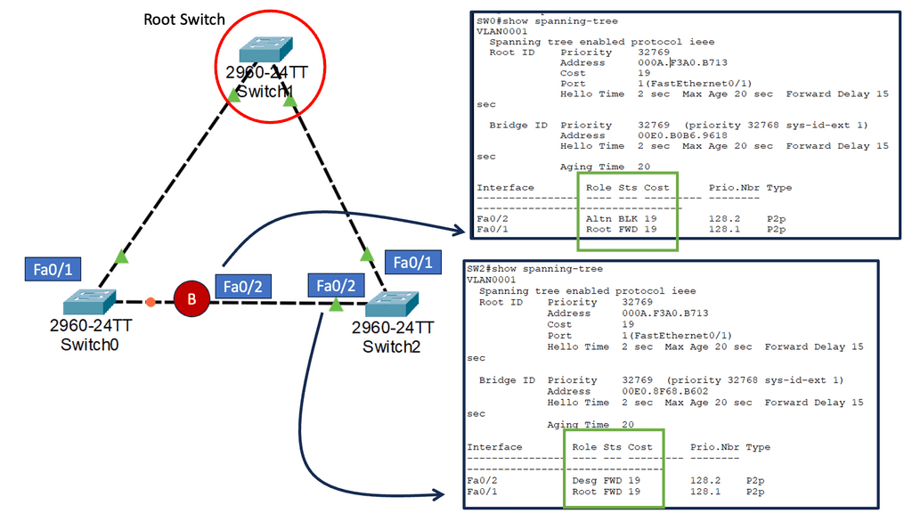
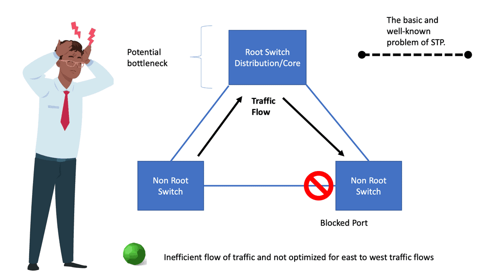
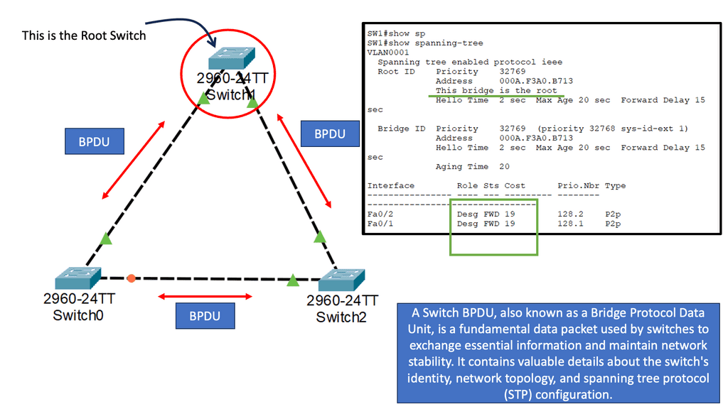
Example: Spanning Tree Uplink Fast
Spanning Tree Protocol (STP) prevents loops in Ethernet networks by creating a loop-free logical topology and blocking redundant paths. While STP ensures network stability, it can also introduce delays in network convergence. Network downtime caused by STP convergence can be a primary concern for businesses. Even a few seconds of downtime can result in significant losses in critical environments. This is where Spanning Tree Uplink Fast comes into play. Uplink Fast is an enhancement to STP that provides faster convergence times, reducing network downtime and improving overall network efficiency.
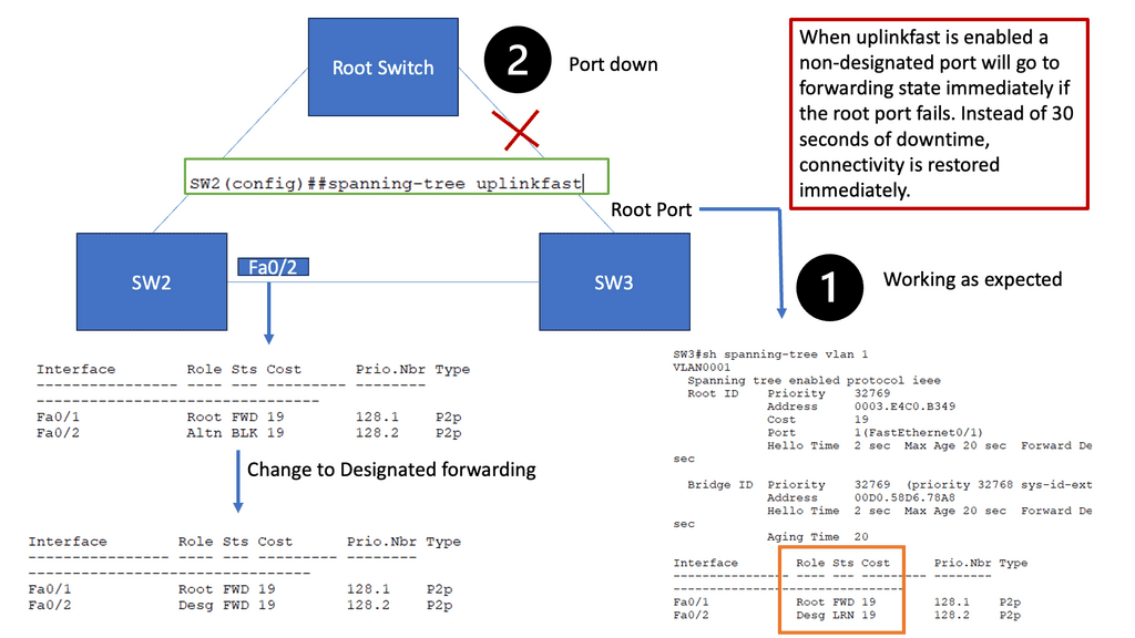
How Uplink Fast Works
Uplink Fast allows a switch to detect a link failure on its designated root port and immediately activate an alternate port. This process eliminates the need for the traditional STP convergence process, resulting in faster network recovery times. Uplink Fast is instrumental when network redundancy is crucial, such as in data centers or enterprise networks.
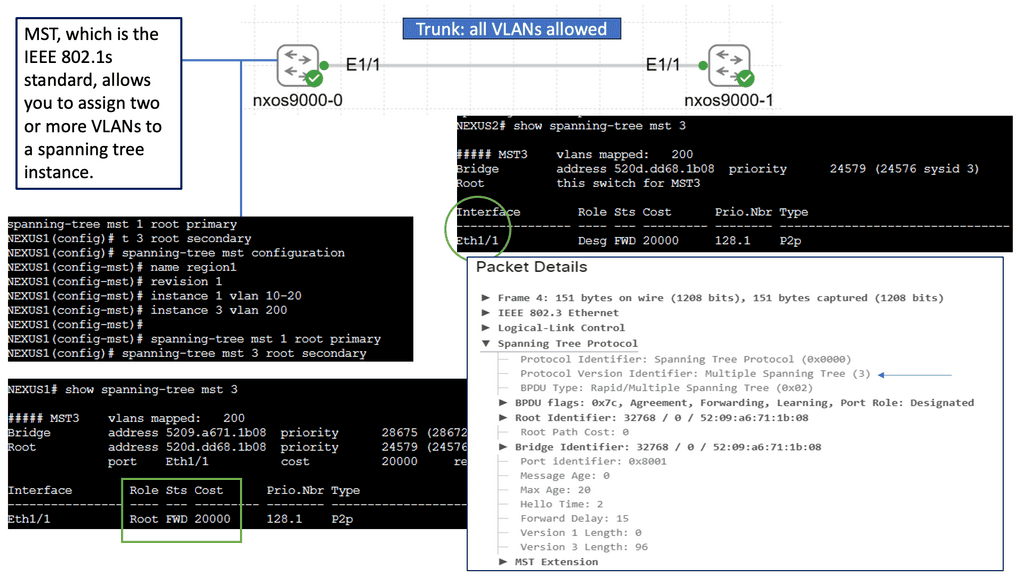
Introducing Spanning Tree MST
Spanning Tree MST enhances the traditional STP, providing a more efficient and flexible solution. MST allows network administrators to divide the network into multiple regions, each with its own Spanning Tree instance. By doing so, MST optimizes network resources and enables load balancing across multiple paths, leading to increased performance and redundancy.
To implement Spanning Tree MST, network switches need to be properly configured. This involves defining regions, assigning VLANs to instances, and configuring parameters such as root bridges and priorities. MST configuration can be complex, but with careful planning and understanding, it offers significant benefits.
Spanning Tree MST offers several key advantages. First, it enables efficient utilization of network resources by load-balancing traffic across multiple paths. Second, it provides enhanced redundancy, ensuring that if one path fails, traffic can automatically reroute through an alternate path. Third, MST simplifies network management by allowing administrators to control traffic flow and prioritize specific VLANs within each instance.
Data Center Security Technologies
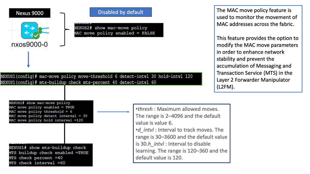
Understanding the MAC Move Policy
The MAC Move Policy is a crucial feature in Cisco NX-OS devices that governs the movement of MAC addresses within a network. By defining specific rules and criteria, administrators can control how MAC addresses are learned, aged, and moved across different interfaces and VLANs.
Configuring the MAC Move Policy
Proper configuration is essential to effectively utilizing the MAC Move Policy. This section will guide you through the step-by-step process of configuring the policy on Cisco NX-OS devices. From defining the MAC move parameters to implementing the policy on specific interfaces or VLANs, we will cover all the necessary commands and considerations to ensure a seamless configuration experience.
Understanding MAC ACLs
MAC ACLs, also known as Ethernet ACLs or Layer 2 ACLs, operate at the data link layer of the OSI model. Unlike traditional IP-based ACLs, which focus on network layer addresses, MAC ACLs allow administrators to filter traffic based on MAC addresses. This enables granular control over network access, providing an additional layer of defense against unauthorized devices.
By implementing MAC ACLs on the Nexus 9000 series, network administrators can exercise enhanced control over their network environment. MAC ACLs prevent MAC address spoofing, mitigating the risk of unauthorized devices gaining access. Furthermore, they enable the isolation of specific devices or groups of devices, ensuring that only designated entities can communicate within a given VLAN or network segment.

Understanding VLANs and ACLs
Before we embark on our journey to explore VLAN ACLs’ potential, let’s establish a solid foundation by understanding VLANs and ACLs individually. VLANs (Virtual Local Area Networks) allow us to logically segment networks, improving performance, scalability, and network management. On the other hand, ACLs (Access Control Lists) act as gatekeepers, controlling traffic flow and enforcing security policies.
VLAN ACLs serve as a crucial layer of defense in protecting our networks from unauthorized access, malicious activities, and potential breaches. By implementing VLAN ACLs, we can define granular rules that filter and restrict traffic between VLANs, ensuring that only desired communication occurs. This level of control empowers network administrators to mitigate risks, maintain data integrity, and enforce compliance.

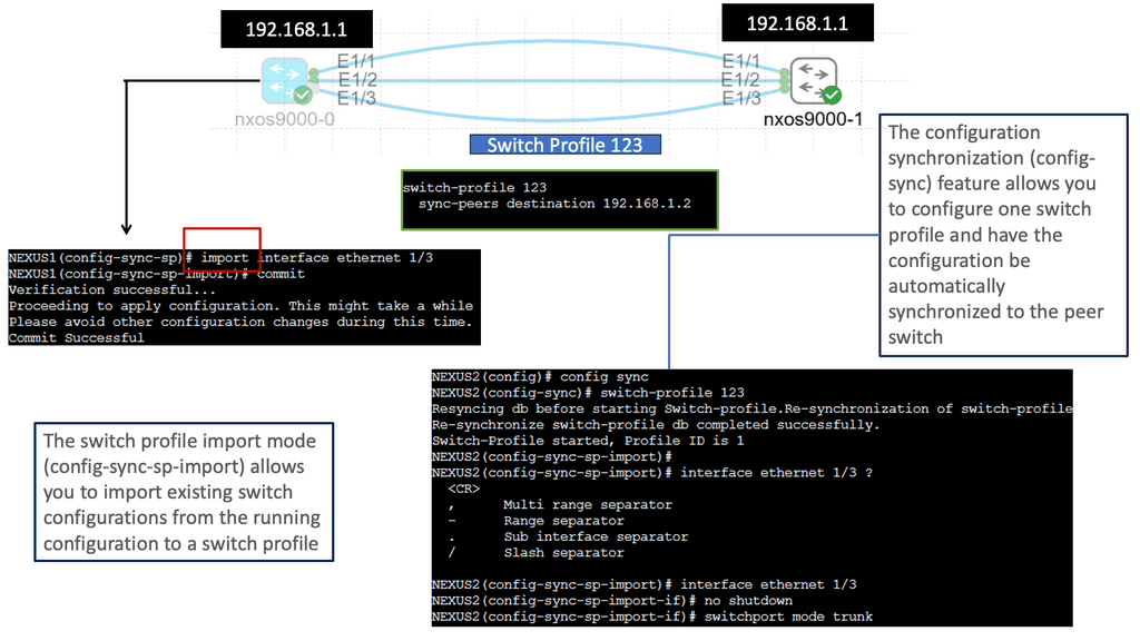
Understanding Nexus Switch Profiles
Nexus switch profiles are a feature of Cisco’s Nexus series switches that allow administrators to define and manage a group of switches as a single entity. By creating a profile, administrators can easily configure and monitor all switches within the group, eliminating the need for repetitive manual configurations. This centralization of management simplifies network administration and saves valuable time and resources.
One of the primary advantages of using Nexus switch profiles is the ability to streamline network operations. With a profile in place, administrators can make changes or updates to configurations across multiple switches simultaneously. This significantly reduces the risk of configuration errors and ensures consistent settings throughout the network. Furthermore, the centralized management approach simplifies troubleshooting and enables faster resolution of network issues.
Data Center Technologies
Understanding Layer 3 Etherchannel
Layer 3 Etherchannel is a link aggregation technique that combines multiple physical links between switches into a single logical channel. By bundling these links together, traffic can be distributed across them, increasing overall bandwidth capacity and providing load-balancing capabilities. Unlike Layer 2 Etherchannel, Layer 3 Etherchannel operates at the network layer, allowing traffic to be routed.
To configure Layer 3 Etherchannel, several steps need to be followed. First, the physical interfaces on the switches need to be identified and grouped into the Etherchannel bundle. Then, a logical interface, the Port-Channel interface, is created and assigned an IP address. Subsequently, routing protocols or static routes can be configured on the Port-Channel interface to enable communication between different networks.
Layer 3 Etherchannel supports various load-balancing algorithms, determining how traffic is distributed across the bundled links. Standard algorithms include source IP, destination IP, and round-robin. Each algorithm has advantages and considerations depending on the network requirements and traffic patterns.

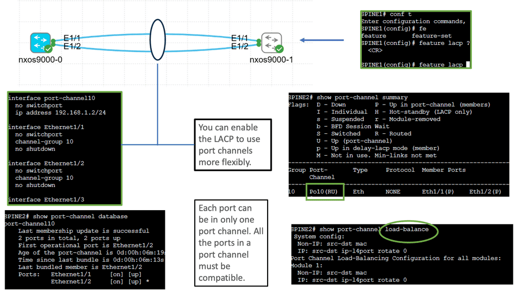
Cisco Nexus 9000 Port Channel
Implementing Port Channels on Cisco Nexus 9000 switches offers several advantages. Firstly, it provides increased link bandwidth, allowing for efficient data transfer and reducing bottlenecks. Secondly, Port Channels enhance network resilience by providing link redundancy. In a link failure, traffic seamlessly switches to the remaining active links. Lastly, Port Channels enable load balancing, distributing network traffic evenly across the aggregated links for optimal utilization.
Setting up a Port Channel on Cisco Nexus 9000 switches is straightforward. Administrators can configure Port Channels using the Link Aggregation Control Protocol (LACP) or the Port Aggregation Protocol (PAgP). Administrators can maximize the benefits of this feature by adequately configuring interfaces and assigning them to the Port Channel.
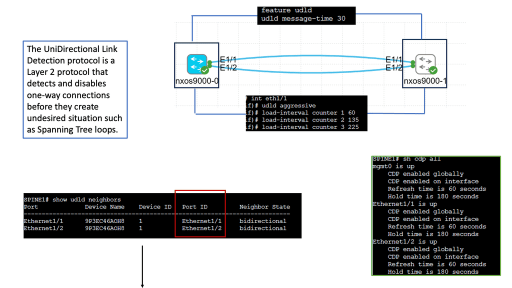
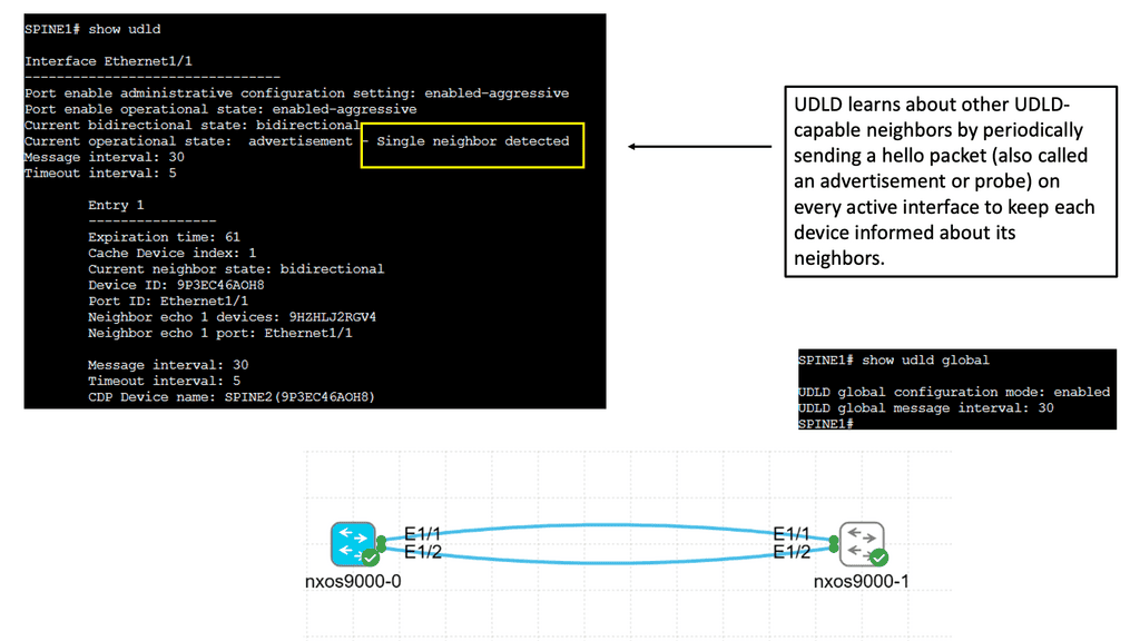
Understanding Unidirectional Link Detection (UDLD)
UDLD is a layer 2 protocol that helps identify and mitigate the presence of unidirectional links in a network. It works by exchanging periodic messages between neighboring switches to verify bidirectional connectivity. By detecting unidirectional links, UDLD helps prevent potential network issues such as black holes, spanning-tree loops, and data loss.
Cisco Nexus 9000 switches offer seamless integration and support for UDLD. To enable UDLD on a Nexus 9000 switch, administrators can utilize simple commands within the switch configuration. By configuring UDLD timers, administrators can customize the frequency of UDLD messages exchanged between switches. Additionally, UDLD can be configured to operate in either standard or aggressive mode, depending on the specific needs of the network environment.
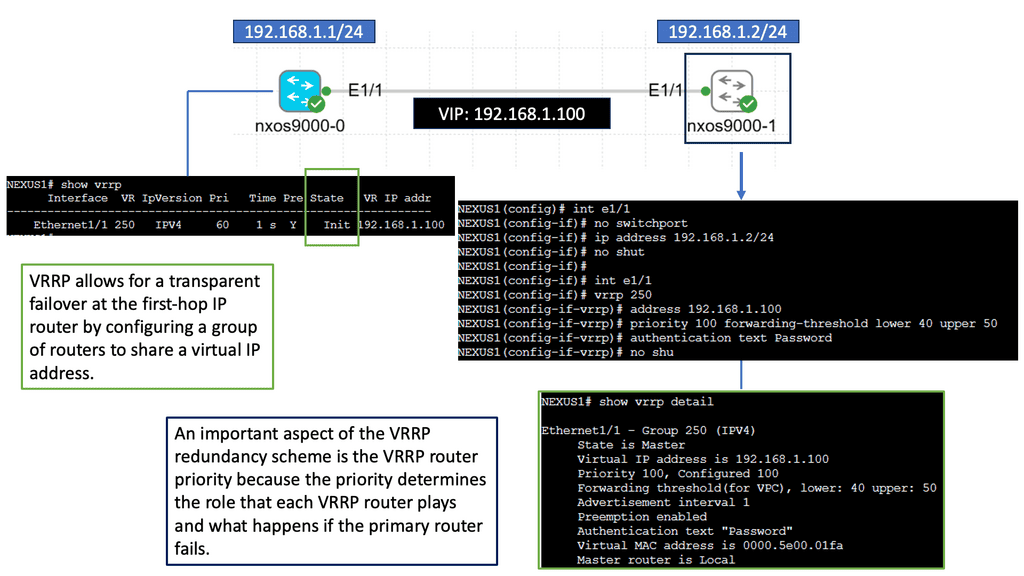
Understanding VRRP
VRRP, an essential networking protocol, provides automatic failover and load-balancing capabilities. It allows multiple routers to work as a virtual group, presenting a single IP address. By intelligently distributing network traffic, VRRP ensures seamless connectivity even in the face of router failures.
The Nexus 9000 Series, Cisco’s flagship product line, offers a range of cutting-edge features, including VRRP. Designed to meet the demands of modern networks, these switches deliver exceptional performance, scalability, and flexibility. With the Nexus 9000 Series, network administrators can harness the power of VRRP to build a robust and highly available network infrastructure.
Example: Data Center WAN Protocol
BGP, also known as the routing protocol of the Internet, is responsible for exchanging routing and reachability information among autonomous systems (AS). It enables routers to make intelligent decisions about the most optimal paths for data transmission. Unlike interior gateway protocols, BGP focuses on routing between different networks rather than within a single network.
BGP operates on a trust-based model, where routers form peer relationships to exchange routing information. These peers establish connections and exchange routing updates, allowing them to build a complete picture of network reachability. BGP uses a sophisticated algorithm that considers multiple factors, such as path length, quality of service, and policy-based decisions, to determine the best route for traffic.
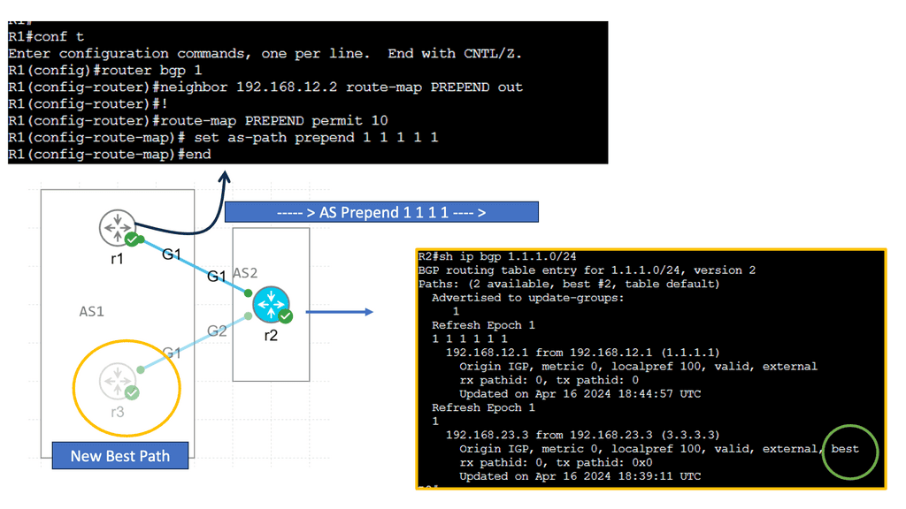
Understanding BGP AS Prepend
AS Prepend involves adding additional Autonomous System (AS) numbers to the AS path attribute of BGP advertisements. By manipulating the AS path, network operators can influence inbound traffic routing decisions by neighboring autonomous systems. This technique makes a specific path appear less desirable, diverting traffic to alternative paths.
AS Prepend holds excellent potential for optimizing network routing in various scenarios. It can achieve load balancing across multiple links, redirect traffic to less congested paths, or prefer specific transit providers. By carefully implementing AS Prepend, network administrators can improve network performance, reduce latency, and enhance overall service quality.
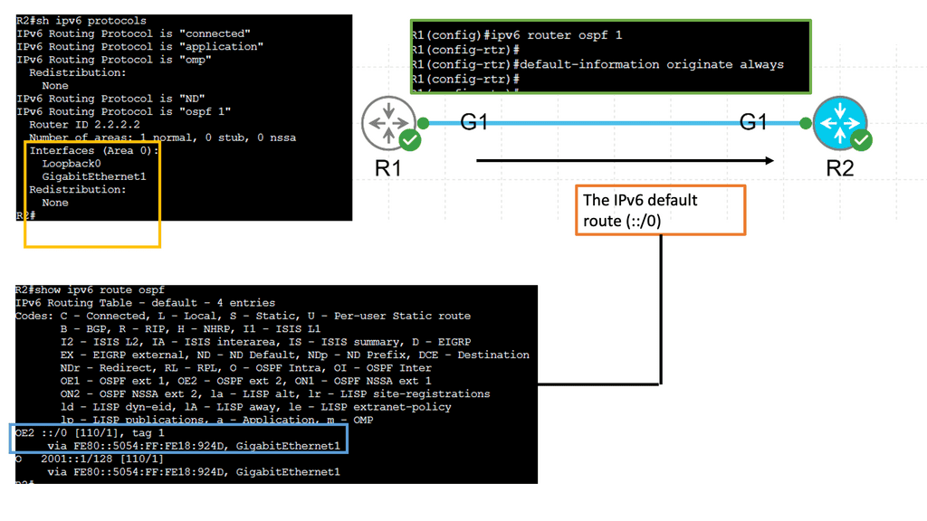
Recap: Border Gateway Protocol (BGP) is data centers’ most commonly used routing protocol. It has been used to connect Internet systems worldwide for decades and can also be used outside a data center. The BGP protocol is a standard-based open-source software package. It’s more common to find BGP peering between data centers over the WAN. However, we see BGP often used purely inside the data center.
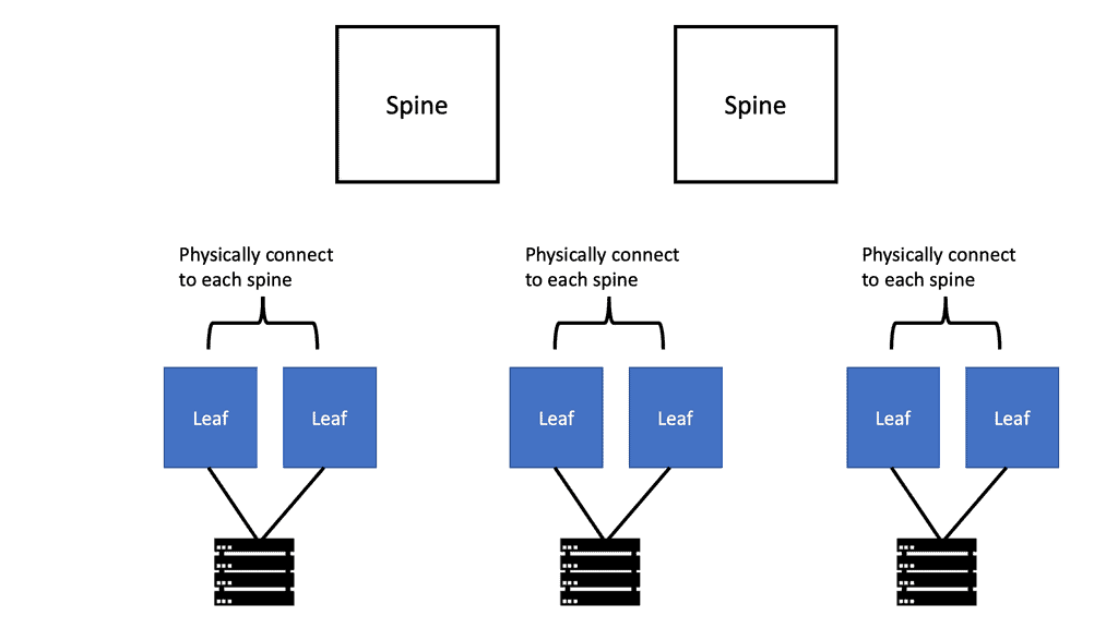
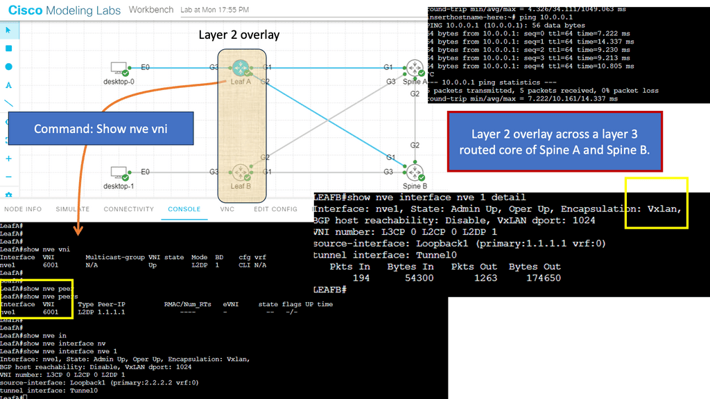
Understanding Leaf and Spine Networks
Leaf and spine networks, also known as Clos networks, are a modern approach to data center architecture. The design revolves around a hierarchical structure consisting of two key components: leaf switches and spine switches. Leaf switches connect directly to endpoints, while spine switches interconnect the leaf switches, forming a non-blocking fabric. This architecture eliminates bottlenecks and enables seamless scalability.
BGP (Border Gateway Protocol) is a crucial routing protocol in leaf and spine networks. It ensures efficient data forwarding between leaf switches using a set of rules known as BGP route advertisements. By default, BGP requires every router to have a full mesh of connections with all other routers in the network, which can be resource-intensive. This is where BGP route reflection comes into play.
Understanding BGP Route Reflection
BGP route reflection, at its core, is a method that allows a BGP speaker to reflect routing information to its peers, alleviating the need for full-mesh connectivity. Designating specific BGP routers as route reflectors streamlines and manages the network structure.
The utilization of BGP route reflection offers several advantages. First, it reduces the number of required BGP peering sessions, resulting in a simplified and less resource-intensive network. Second, route reflection enhances scalability by eliminating the need for full-mesh connectivity, particularly in large-scale networks. Third, it improves convergence time and reduces BGP update processing overhead, enhancing overall network performance.


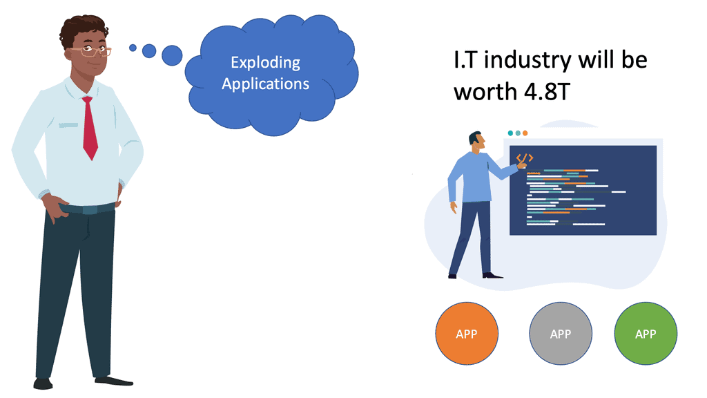
**The third wave of application architectures**
Google and Amazon, two of the world’s leading web-scale pioneers, developed a modern data center. The third wave of application architectures represents these organizations’ search and cloud applications. Towards the end of the 20th century, client-server architectures and monolithic single-machine applications dominated the landscape. This third wave of applications has three primary characteristics:
Unlike client-server architectures, modern data center applications involve a lot of communication between servers. In client-server architectures, clients communicate with monolithic servers, which either handle the request entirely themselves or communicate with fewer than a handful of other servers, such as database servers. Search (or Hadoop, its more popular variant) employs many mappers and reducers instead of search. In the cloud, virtual machines can reside on different nodes but must communicate seamlessly. In some cases, VMs are deployed on servers with the least load, scaled out, or balanced loads.
A microservices architecture also increases server-to-server communication. This architecture is based on separating a single function into smaller building blocks and interacting with them. Each block can be used in several applications and enhanced, modified, and fixed independently in such an architecture. Since diagrams usually show servers next to each other, East-West traffic is often called server communication. Traffic flows north-south between local networks and external networks.
**Scale and resilience**
The sheer size of modern data centers is characterized by rows and rows of dark, humming, blinking machines. As opposed to the few hundred or so servers of the past, a modern data center contains between a few hundred and a hundred thousand servers. To address the connectivity requirements at such scales, as well as the need for increased server-to-server connectivity, network design must be rethought. Unlike older architectures, modern data center applications assume failures as a given. Failures should be limited to the smallest possible footprint. Failures must have a limited “blast radius.” By minimizing the impact of network or server failures on the end-user experience, we aim to provide a stable and reliable experience.
**Data Center Goal: Interconnect networks**
The goal of data center design and interconnection network is to transport end-user traffic from A to B without any packet drops, yet the metrics we use to achieve this goal can be very different. The data center is evolving and progressing through various topology and technology changes, resulting in multiple network designs. The new data center control planes we see today, such as Fabric Path, LISP, THRILL, and VXLAN, are driven by a change in the end user’s requirements; the application has changed. These new technologies may address new challenges, yet the fundamental question of where to create the Layer 2/Layer three boundaries and the need for Layer 2 in the access layer remains the same. The question stays the same, yet the technologies available to address this challenge have evolved.
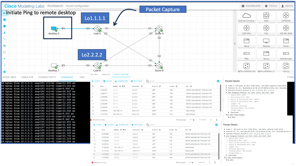
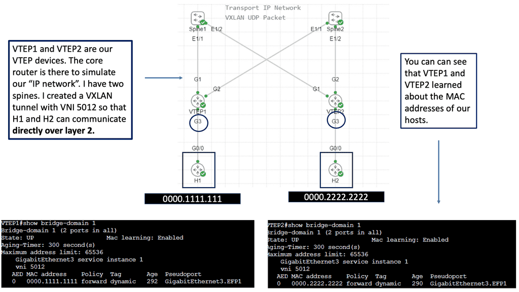
Example Protocol: Understanding VXLAN
VXLAN, an encapsulation protocol, enables the creation of virtualized Layer 2 networks over an existing Layer 3 infrastructure. By extending the Layer 2 domain, VXLAN allows the seamless transfer of network traffic between geographically dispersed data centers. It achieves this by encapsulating Ethernet frames within IP packets, providing flexibility and scalability to network virtualization.
Scalability and Flexibility: VXLAN addresses the limitations of traditional VLANs by allowing for a significantly more significant number of virtual networks—up to 16 million—compared to the 4,096 limit of VLANs. This scalability enables organizations to allocate virtual networks more efficiently while accommodating the growing demands of cloud-based applications and services.
Enhanced Network Segmentation and Isolation: VXLAN provides improved network segmentation by creating logical networks that are isolated from one another, even if they share the same physical infrastructure. This isolation enhances security and enables more granular control over network traffic, facilitating efficient multi-tenancy in cloud environments.
Modern Data Centers
There is a vast difference between modern data centers and what they used to be just a few years ago. Physical servers have evolved into virtual networks that support applications and workloads across pools of physical infrastructure and into a multi-cloud environment. There are multiple data centers, the edge, and public and private clouds where data exists and is connected. Both on-premises and cloud-based data centers must be able to communicate. Data centers are even part of the public cloud. Cloud-hosted applications use the cloud provider’s data center resources.
Unified Fabric
Through Cisco’s fabric-based data center infrastructure, tiered silos and inefficiencies of multiple network domains are eliminated, and a unified, flat fabric is provided instead, which allows local area networks (LANs), storage area networks (SANs), and network-attached storage (NASs) to be consolidated into one high-performance, fault-tolerant network. Creating large pools of virtualized network resources that can be easily moved and rapidly reconfigured with Cisco Unified Fabric provides massive scalability and resiliency to the data center.
This approach automatically deploys virtual machines and applications, thereby reducing complexity. Thanks to deep integration between server and network architecture, secure IT services can be delivered from any device within the data center, between data centers, or beyond. In addition to Cisco Nexus switches, Cisco Unified Fabric uses Cisco NX-OS as its operating system.
The use of Open Networking
We also have the Open Networking Foundation ( ONF ), which provides open networking. Open networking describes a network that uses open standards and commodity hardware. So, consider open networking in terms of hardware and software. Unlike a vendor approach like Cisco, this gives you much more choice with what hardware and software you use to make up and design your network.
Data Center Performance Parameters
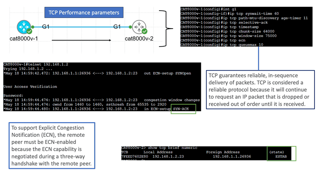
TCP Performance Parameters
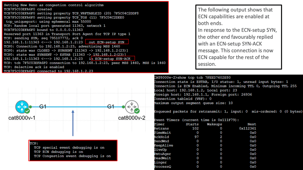
TCP (Transmission Control Protocol) is the backbone of modern Internet communication, ensuring reliable data transmission across networks. However, various parameters that determine TCP’s behavior can influence its performance.
Understanding TCP Window Size: One crucial parameter that affects TCP performance is the window size. The TCP window size refers to the amount of data sent before an acknowledgment is required. A larger window size allows more data to be transmitted without waiting for acknowledgments, thus optimizing throughput. However, substantial window sizes can result in congestion and increased retransmissions.
Congestion Control Mechanisms: Congestion control mechanisms are vital in maintaining network stability and preventing congestion collapse. TCP utilizes algorithms such as Slow Start, Congestion Avoidance, and Fast Recovery to regulate data flow based on network conditions. These mechanisms ensure fairness and efficiency, improving TCP performance and avoiding network congestion.
Timeouts and Retransmission: TCP implements a reliable data transfer mechanism using acknowledgments and timeouts. When a packet is not acknowledged within a specific timeframe, it is considered lost, and TCP initiates retransmission. The selection of appropriate timeout values is crucial to balance reliability and responsiveness. Setting shorter timeouts may lead to unnecessary retransmissions, whereas longer ones can increase latency.
Selective Acknowledgments and SACK Options: Selective acknowledgments (SACK) enhance TCP performance and recovery from packet loss. SACK lets the receiver inform the sender about specific out-of-order packets received successfully. This enables the sender to retransmit only the necessary packets, reducing unnecessary retransmissions and improving overall efficiency.
Maximum Segment Size (MSS): The Maximum Segment Size (MSS) is another crucial TCP performance parameter defining the maximum amount of data encapsulated within a single TCP segment. Optimizing the MSS can significantly impact performance, especially when network links have different MTU (Maximum Transmission Unit) sizes.
Understanding TCP MSS
TCP MSS refers to the maximum amount of data encapsulated within a single TCP segment. It represents the size of the payload, excluding headers and other overhead. The MSS value is negotiated during the TCP handshake process and remains constant throughout the connection.
The TCP MSS value has a direct impact on network performance and efficiency. Setting an appropriate MSS value ensures optimal network resource utilization and avoids unnecessary data packet fragmentation. Properly configuring TCP MSS becomes crucial when networks have different MTU (Maximum Transmission Unit) sizes.
Fragmentation occurs when the MSS value exceeds the MTU of a network path. This fragmentation can lead to performance degradation, increased latency, and potential packet loss. By carefully managing the TCP MSS value, network administrators can prevent or minimize fragmentation issues and enhance overall network performance.
Configuring TCP MSS requires a thorough understanding of the network infrastructure and the devices involved. It involves adjusting the MSS value at various points within the network, such as routers, firewalls, and load balancers. Aligning the TCP MSS value with the MTU of the underlying network ensures efficient data transmission and avoids unnecessary fragmentation.

Advanced Topics
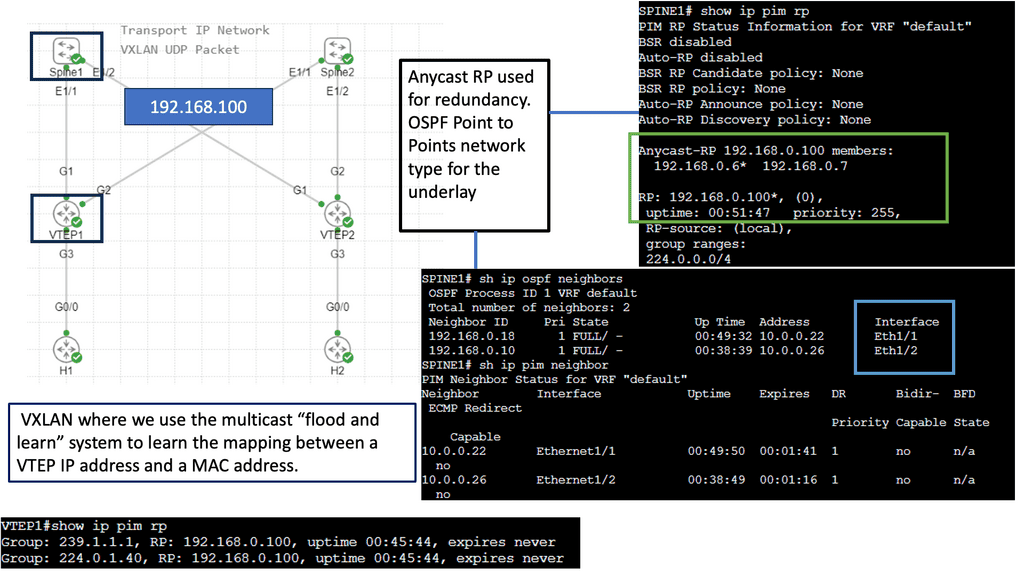
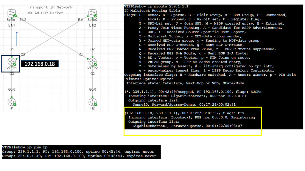
VXLAN Flood and Learn Mechanism
The flood-and-learn mechanism in VXLAN plays a crucial role in facilitating communication between virtual machines within the overlay network. When a virtual machine sends a broadcast or unknown unicast frame, the frame is encapsulated in a VXLAN packet and flooded throughout the network. Each VXLAN tunnel endpoint (VTEP) learns the source MAC address and VTEP association, enabling subsequent unicast traffic to be directly delivered.
Multicast is a fundamental component of VXLAN flood and learn, offering several benefits. First, using multicast VXLAN reduces bandwidth consumption compared to traditional flooding techniques. Second, multicast enables efficient replicating broadcast, multicast, and unknown unicast traffic across the overlay network. Third, it enhances network scalability by eliminating the need to maintain a multicast group per tenant.

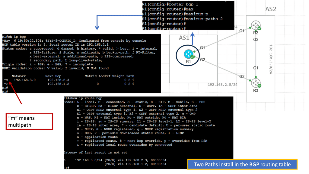
BGP Multipath
Understanding BGP Multipath
BGP multipath is a feature that enables the installation and usage of multiple paths for a single prefix in the routing table. Traditionally, BGP selects a single best path based on factors such as AS path length, origin type, and path attributes. However, with multipath enabled, BGP can utilize multiple paths simultaneously, distributing traffic across them for load balancing and redundancy purposes.
The utilization of BGP multipath brings several advantages to network operators. First, it enhances network resilience by providing redundant paths. In the event of a link failure or congestion, traffic can be automatically rerouted through available alternate paths, ensuring continuous connectivity. Additionally, BGP multipath facilitates load balancing, enabling more efficient utilization of network resources and better traffic distribution across multiple links.
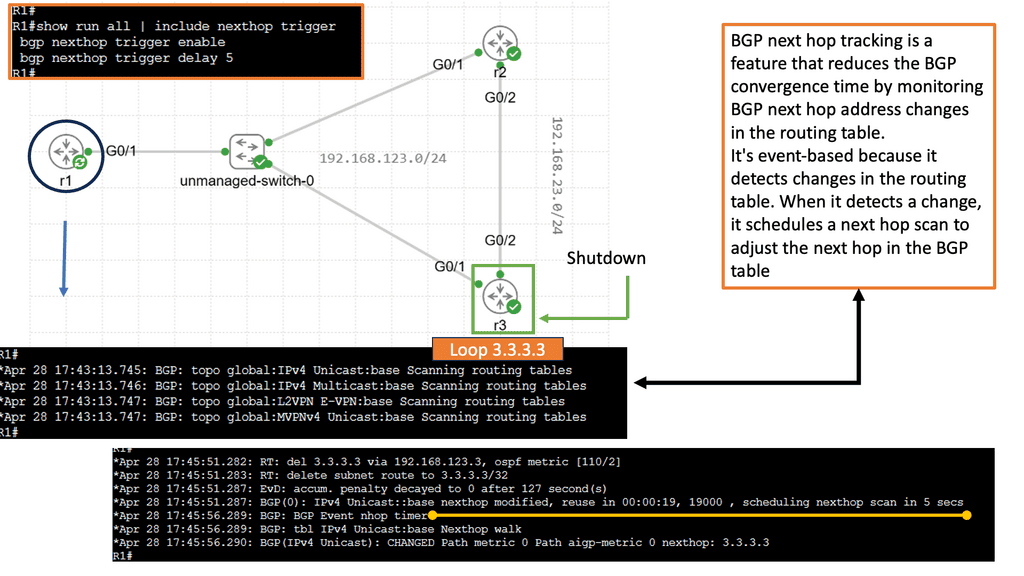
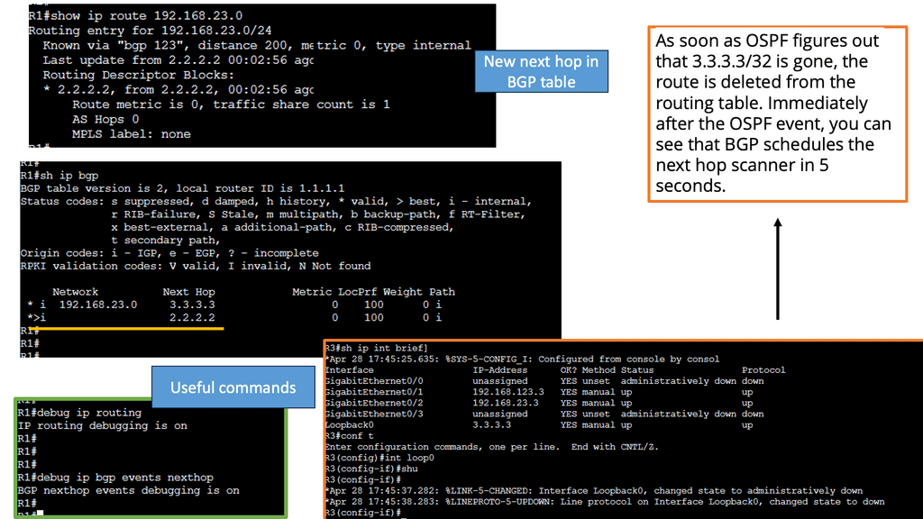
Understanding BGP Next Hop Tracking
BGP next-hop tracking monitors the reachability of the next-hop IP address associated with a particular route. It allows routers to dynamically adjust their routing tables based on changes in the network topology. Routers can make informed decisions about forwarding traffic by continuously tracking the next hop, ensuring optimal path selection.
Enhanced Network Resiliency: BGP next-hop tracking enables routers to detect and respond to network changes quickly. If a next hop becomes unreachable, routers can automatically reroute traffic to an alternative path, minimizing downtime and improving network resiliency.
Load Balancing and Traffic Engineering: Network administrators gain granular control over traffic distribution with BGP next-hop tracking. By monitoring the reachability of multiple next hops, routers can intelligently distribute traffic across different paths, optimizing resource utilization and improving overall network performance.
Improved Network Convergence: Rapid convergence is crucial in dynamic networks. BGP next hop tracking facilitates faster convergence by promptly updating routing tables when next hops become unreachable. This ensures routing decisions are based on current information, reducing packet loss and minimizing network disruptions.
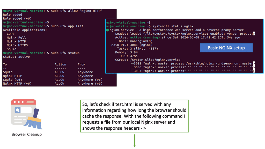
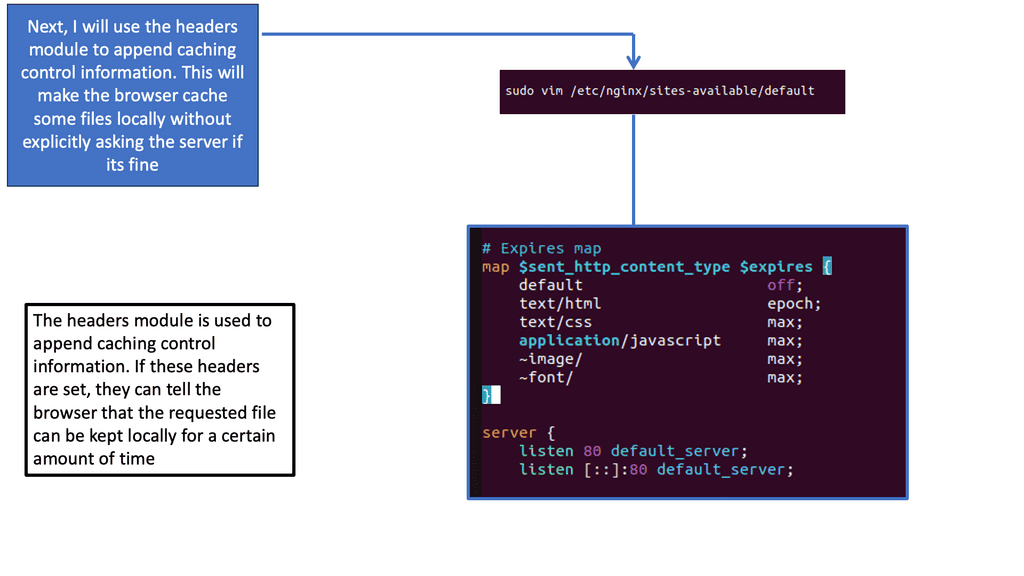
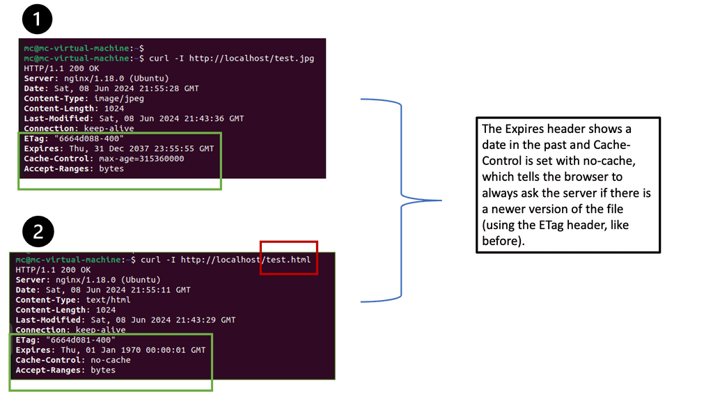
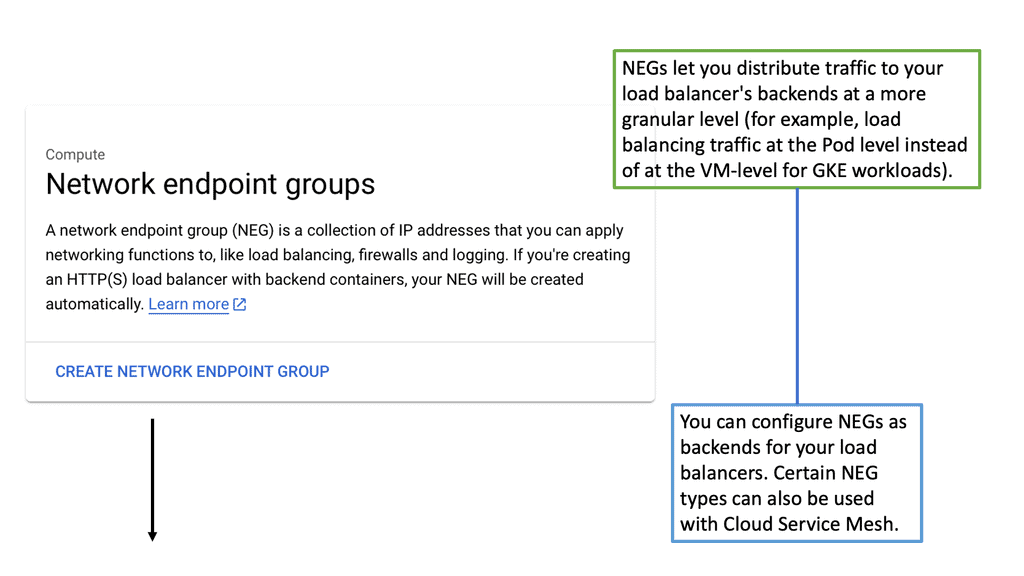
Related: Before you proceed, you may find the following useful:
- ACI Networks
- IPv6 Attacks
- SDN Data Center
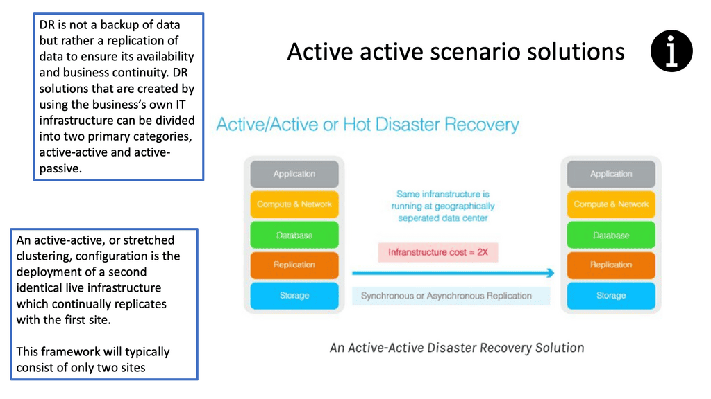
- Active Active Data Center Design
- Virtual Switch