opencontrail

OpenContrail

OpenContrail

In today's fast-paced world, where cloud computing and virtualization have become the norm, the need for efficient and flexible networking solutions has never been greater. OpenContrail, an open-source software-defined networking (SDN) solution, has emerged as a powerful tool. This blog post explores the capabilities, benefits, and significance of OpenContrail in revolutionizing network management and delivering enhanced connectivity in the cloud era.

OpenContrail, initially developed by Juniper Networks, is an open-source SDN platform offering comprehensive network capabilities for cloud environments. It provides a scalable and flexible network infrastructure that enables automation, network virtualization, and secure multi-tenancy across distributed cloud deployments.

OpenContrail, an open-source network virtualization platform, is designed to simplify the management and orchestration of virtual networks. Built on well-established technologies such as OpenStack and SDN, it provides a comprehensive set of tools and APIs to create and manage virtualized network services. With OpenContrail, organizations can achieve greater scalability, security, and performance while reducing operational complexities.

Virtual Network Overlays: OpenContrail leverages virtual network overlays to create isolated and secure network segments, allowing for seamless multi-tenancy and network segmentation.

Network Policy and Security: It offers fine-grained network policies to control traffic flow, implement access control, and enforce security measures at the virtual network level.

Analytics and Monitoring: OpenContrail provides advanced analytics and monitoring capabilities, allowing administrators to gain insights into network performance, troubleshoot issues, and optimize resource allocation.

Cloud Service Providers: OpenContrail empowers cloud service providers to deliver scalable and secure network services to their customers. It enables seamless provisioning of virtual networks, ensuring high-performance connectivity and efficient resource utilization.

Enterprise Networks: Enterprises can leverage OpenContrail to build agile and flexible network infrastructures. It simplifies network management, enables seamless integration with existing infrastructure, and provides enhanced security measures.

Internet of Things (IoT): With the proliferation of IoT devices, OpenContrail offers a robust solution for managing and securing large-scale IoT deployments. It enables efficient communication between devices, ensures data privacy, and provides centralized control over IoT network resources.

OpenContrail proves to be a groundbreaking solution in the realm of network virtualization. Its feature-rich architecture, open-source nature, and diverse real-world applications make it an invaluable tool for organizations seeking to optimize network performance, enhance security, and embrace the future of virtualized networks.

Highlights: OpenContrail

Understanding OpenContrail

OpenContrail is an open-source software-defined networking (SDN) solution that enables the creation and management of virtual networks. It provides a scalable and flexible networking platform that simplifies network provisioning, enhances security, and optimizes network performance. By leveraging OpenContrail, organizations can effectively address the challenges posed by traditional networking approaches.

**Key Features and Benefits**

OpenContrail offers a wide range of powerful features that set it apart from traditional networking solutions. One of its key features is network virtualization, which allows the creation of isolated virtual networks within a physical network infrastructure.

This enables organizations to achieve greater agility and scalability, as well as efficient resource utilization. Additionally, OpenContrail provides advanced security measures, including micro-segmentation, that help protect sensitive data and prevent unauthorized access.

**Use Cases and Industry Applications**

OpenContrail is versatile and can be applied across various industries and use cases. In the telecommunications sector, it supports network slicing and virtual network functions (VNFs), crucial for deploying 5G networks. Enterprises use OpenContrail to create agile and scalable cloud environments, facilitating faster application deployment and improving overall operational efficiency.

Additionally, OpenContrail’s robust security features make it a preferred choice for sectors that require stringent data protection measures, such as finance and healthcare. By providing micro-segmentation and advanced threat detection, OpenContrail helps organizations safeguard their sensitive information.

Open-source network virtualization platform

OpenContrail is an open-source network virtualization platform that enables the creation of virtual networks overlaying physical infrastructure. It provides a scalable and flexible solution for managing network resources, improving security, and enhancing overall network performance. By decoupling the network control plane from the data plane, OpenContrail brings a new level of agility and efficiency to network operations.

1. Virtual Network Creation: OpenContrail allows the creation of virtual networks, each with its own isolated environment, policies, and routing tables. This enables organizations to achieve multi-tenancy and securely isolate their applications and workloads.

2. Network Automation and Orchestration: With OpenContrail, network provisioning and management become automated and orchestrated. This reduces manual configuration efforts and brings more consistency and reliability to network operations.

3. Enhanced Security: OpenContrail provides advanced security features such as micro-segmentation, distributed firewalling, and traffic isolation. These capabilities ensure that applications and data remain protected and isolated, even in complex and dynamic network environments.

Understanding OpenContrail components

Controller Node: At the heart of OpenContrail lies the Controller Node, which acts as the brain of the network. It is responsible for managing and orchestrating all the network services, including configuration, control, and analytics. Through its intuitive and user-friendly interface, network administrators can easily define and enforce policies, monitor network performance, and troubleshoot issues.

vRouter: The vRouter, short for virtual router, is a critical component of OpenContrail that ensures efficient packet forwarding within the network. By combining the power of virtualization and routing, the vRouter enables seamless communication between virtual machines and physical hosts. It provides advanced networking capabilities, such as firewalling, NAT, and VPN, while ensuring high performance and scalability.

Analytics Node: To gain valuable insights into network behavior and performance, OpenContrail incorporates an Analytics Node. This component collects and analyzes network data, generating comprehensive reports and metrics. Network operators can leverage this information to optimize network utilization, identify bottlenecks, and proactively address potential issues. The Analytics Node plays a crucial role in ensuring the reliability and efficiency of the entire network infrastructure.

Web User Interface: OpenContrail offers a user-friendly Web User Interface (UI) that simplifies network management and configuration. With its intuitive design and powerful functionalities, network administrators can easily define network topologies, set up policies, and monitor network performance in real time. The Web UI provides a centralized platform for managing the entire network infrastructure, making deploying, scaling, and maintaining OpenContrail deployments easier.

The traditional network vs. SDN network

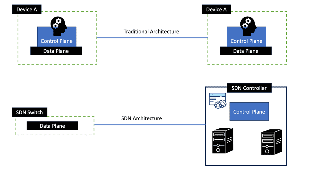
In a traditional network, each switch/router must be programmed individually because applications are loaded. These applications could include a load balancer, intrusion detection, monitoring, or Voice over IP (VoIP). Based on local logic, each switch/router decides where to route packets as traffic flows through the network. Changing applications or flows in this network requires systematically programming each switch/router.

A traditional network includes both a control plane and a forwarding plane. There are also applications loaded on each device, which must be configured separately.

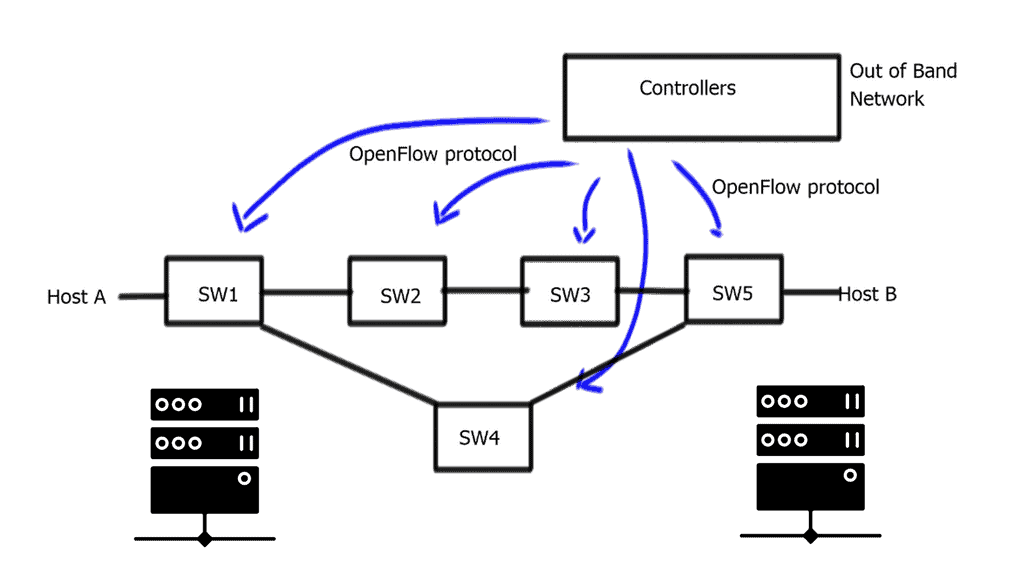
In an SDN network, a switch/router is not connected to any applications or intelligence. By centralized control of all devices, the network becomes programmable. A controller interfaces with applications, which are then executed across a network. Traffic flows are now supervised by a centralized controller that distributes and manages a flow table for each switch/router. Several factors can be used to define very flexible flow tables.

The flow table also collects statistics, which are fed up to the controller. This improves both visibility and control of the network because issues are immediately reported to the controller, which, in turn, can make immediate adjustments across the entire network.

The role of The VM

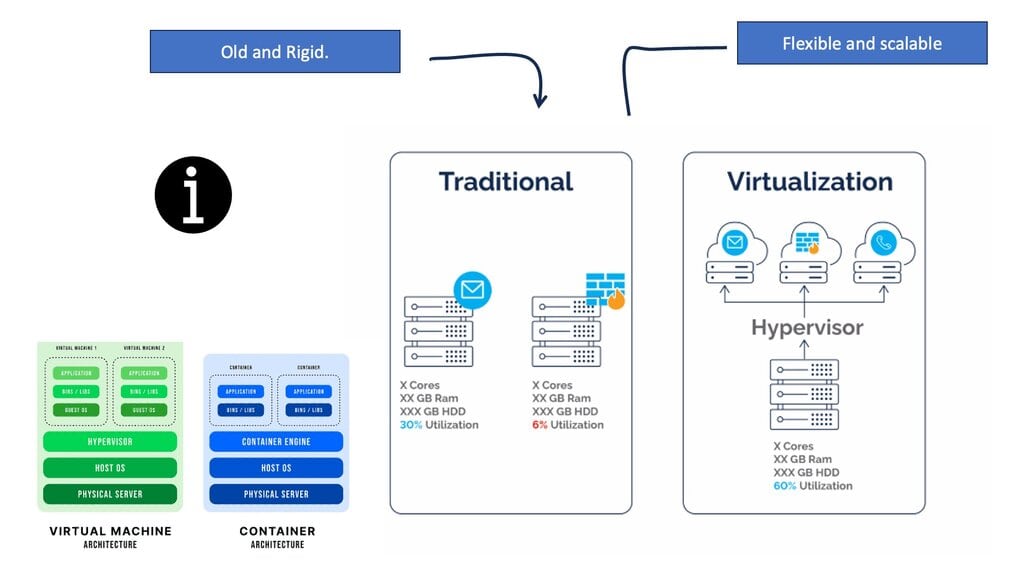
Virtual machines have been around for a long time, but we are beginning to spread our computing workloads in several ways. When you throw in docker containers and bare metal servers, networking becomes more interesting. Network challenges arise when all these components require communication within the same subnet, access to Internet gateways, and Layer 3 MPLS/VPNs.

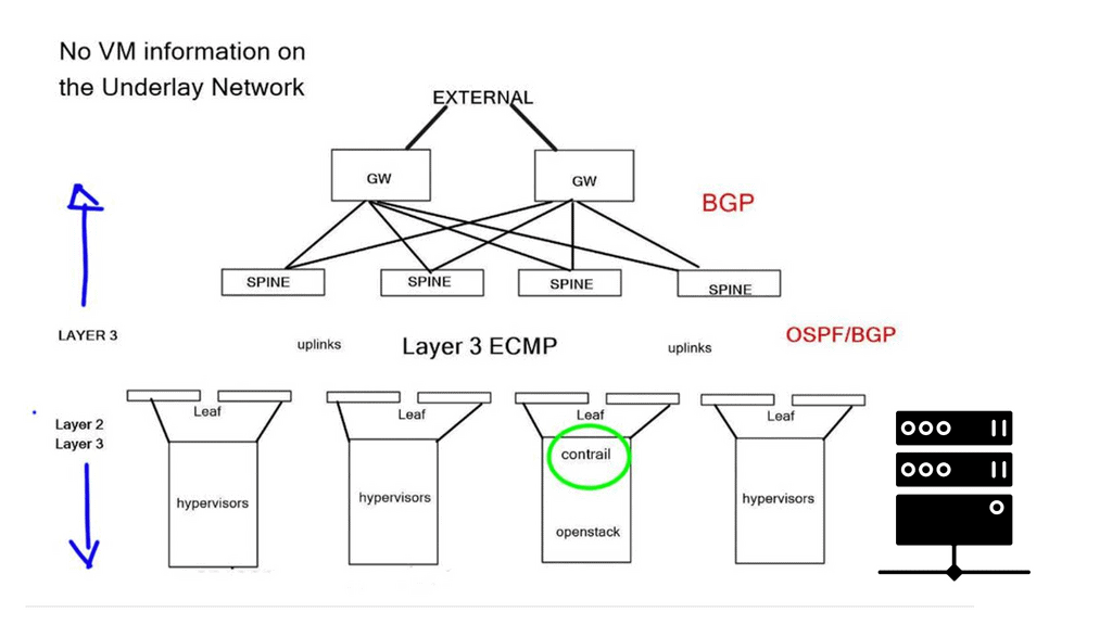
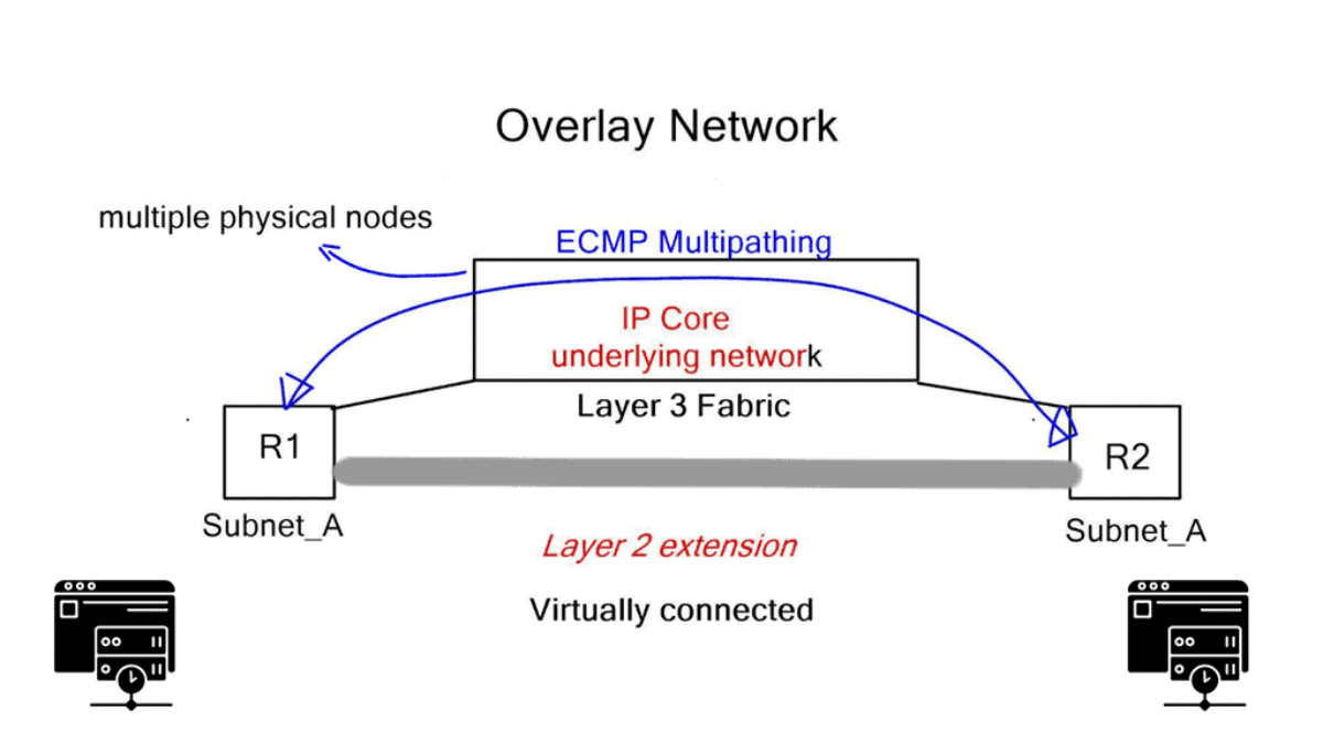
As a result, data center networks are moving towards IP underlay fabrics and Layer 2 overlays. Layer 3 data plane forwarding utilizes efficient Equal-cost multi-path routing (ECMP), but we lack Layer 2 multipathing by default. Now, similar to an SD WAN overlay approach, we can connect dispersed layer 2 segments and leverage all the good features of the IP underlay. To provide Layer 2 overlays and network virtualization, Juniper has introduced an SDN platform called Junipers OpenContrail in direct competition with

Virtualization

For additional pre-information, you may find the following post of use.

  1. ACI Cisco
  2. Network Traffic Engineering
  3. Spine Leaf Architecture
  4. IP Forwarding
  5. SDN Data Center
  6. Network Overlays
  7. Application Traffic Steering
  8. What is BGP Protocol in Networking

Highlights: OpenContrail

Key Features and Benefits:

Network Virtualization:

OpenContrail leverages network virtualization techniques to provide isolated virtual networks within a shared physical infrastructure. It offers a logical abstraction layer, enabling the creation of virtual networks that operate independently, complete with their own routing, security, and quality of service policies. This approach allows for the efficient utilization of resources, simplified network management, and improved scalability.

Secure Multi-Tenancy:

OpenContrail’s security features ensure tenants’ data and applications remain isolated and protected from unauthorized access. It employs micro-segmentation to enforce strict access control policies at the virtual machine level, reducing the risk of lateral movement within the network. Additionally, OpenContrail integrates with existing security solutions, enabling the implementation of comprehensive security measures.

Intelligent Automation:

OpenContrail automates various network provisioning, configuration, and management tasks, reducing manual intervention and minimizing human errors. Its programmable API and centralized control plane simplify the deployment of complex network topologies, accelerate service delivery, and enhance overall operational efficiency.

Scalability and Flexibility:

OpenContrail’s architecture is designed to scale seamlessly, supporting distributed cloud deployments across multiple locations. It offers a highly flexible solution that can adapt to changing network requirements, allowing administrators to dynamically allocate resources, establish new connectivity, and respond to evolving business needs.

OpenContrail in Practice:

OpenContrail has gained significant traction among cloud providers, service providers, and enterprises seeking to build robust, scalable, and secure networks. Its open-source nature has facilitated its adoption, encouraging collaboration, innovation, and customization. OpenContrail’s community-driven development model ensures continuous improvement and the availability of new features and enhancements.
opencontrail
Diagram: OpenContrail.

Highlighting Junipers OpenContrail

OpenContrail is an open-source network virtualization platform. The commercial controller and open-source product are identical; they share the same checksum on the binary image. Maintenance and support are the only difference. Juniper decided to open source to fit into the open ecosystem, which wouldn’t have worked in a closed environment.

OpenContrail offers features similar to VMware NSX, can apply service chaining and high-level security policies, and provides connections to Layer 3 VPNs for WAN integration. OpenContrail works with any hardware, but integration with Juniper’s product sets offers additional rich analytics for the underlay network.

Underlay and overlay network visibility are essential for troubleshooting. You need to look further than the first header of the packet; you need to look deeper into the tunnel to understand what is happening entirely. 

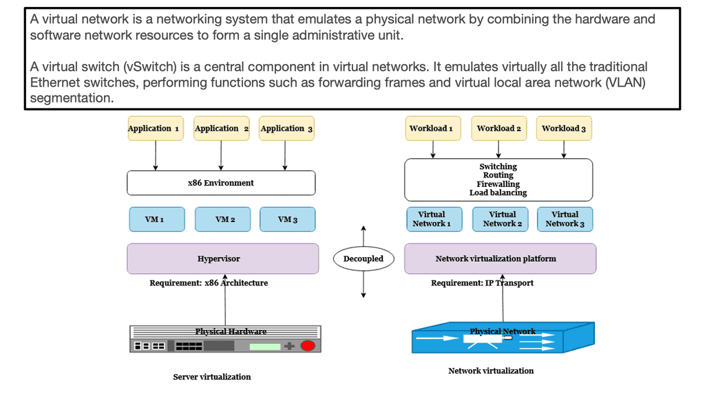
Network virtualization – Isolated networks

With a cloud architecture, network virtualization gives the illusion that each tenant has a separate isolated network. Virtual networks are independent of physical network location or state, and nodes within the physical underlay can fail without disrupting the overlay tenant. A tenant may be a customer or department, depending if it’s a public or private cloud.

The virtual network sits on top of a physical network, the same way the compute virtual machines sit on top of a physical server. Virtual networks are not created with VLANs; Contrail uses a virtual overlay network system for multi-tenancy and cross-tenant communication. Many problems exist with large-scale VLAN deployments for multi-tenancy in today’s networks.

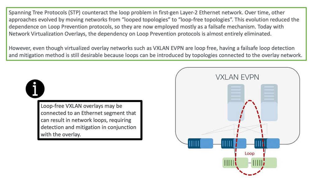
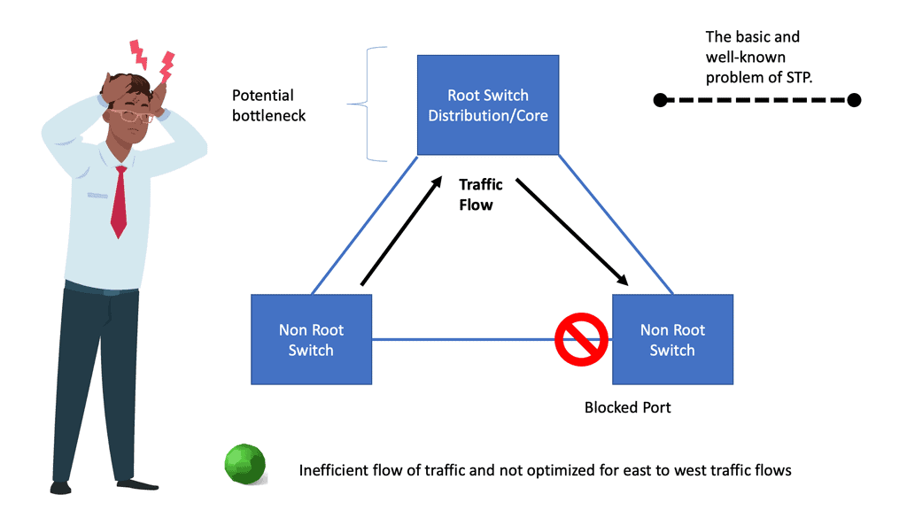
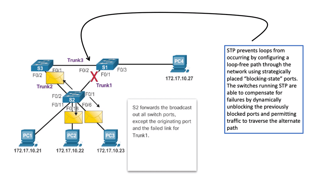
They introduce a lot of states in the physical network, and the Spanning Tree Protocol (STP) also introduces well-documented problems. There are technologies (THRILL, SPB) to overcome these challenges, but they add complexity to the design of the network.

Service Chaining

Customers require the ability to apply policy at virtual network boundaries. Policies may include ACL and stateless firewalls provided within the virtual switch. However, once you require complicated policy pieces between virtual networks, you need a more sophisticated version of policy control and orchestration called service chaining. Service chaining applies intelligent services between traffic from one tenant to another.

For example, if a customer requires content caching and stateful services, you must introduce additional service appliances and force next-hop traffic through these appliances. Once you deploy a virtual appliance, you need a scale-out architecture.

The ability to Scale-out

Scale-out is the ability to instantiate multiple physical and virtual machine instances and load balance traffic across them. Customers may also require the ability to connect with different tenants in dispersed geographic locations or to workloads in a remote private cloud or public cloud. Usually, people build a private cloud for the norm and then burst into a public cloud. 

Juniper has implemented a virtual networking architecture that meets these requirements. It is based on well-known technology, MPLS/layer 3 VPN. MPLS/layer 3 VPN is the base for Juniper designs.

MPLS Overlay

Virtual Network Implementation

A – MPLS Overlay

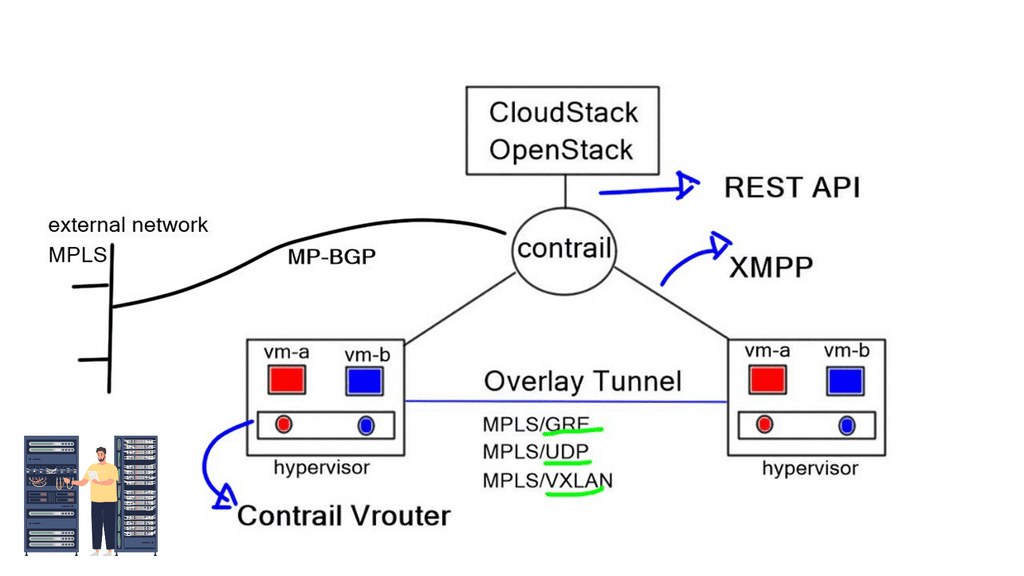
The SDN controller is responsible for the networking aspects of virtualization. When creating virtual networks, initiate the Northbound API and issue an instruction that attaches the VM to the VN. The network responsibilities are delegated from Cloudstack or OpenStack to Contrail. The Contrail SDN controller automatically creates the overlay tunnel between virtual machines. The overlay can be either an MPLS overlay style with MPLS-over-GREMPLS-over-UDP, or VXLAN

L3VPN for routed traffic and EVPN for bridged traffic

Juniper’s OpenContrail is still a pure MPLS overlay of MPLS/VPN, using L3VPN for routed traffic and EVPN for bridged traffic. Traffic forwarding between end nodes has one MPLS label (VPN label), but they use various encapsulation methods to carry labeled traffic across the IP fabric. As mentioned above, this includes MPLS-over-GRE – a traditional encapsulation mechanism, MPLS-over-UDP – a variation of MPLS-over-GRE that replaces the GRE headers with UDP headers. MPLS-over-VXLAN uses VXLAN packet format but stores the MPLS label in the Virtual Network Identifier (VNI) field.

B – The forwarding plane

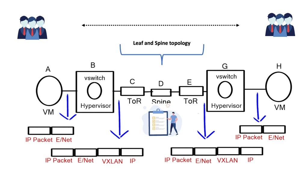
The forwarding plane takes the packet from the VM and gives it to the “Vrouter,” which does a lookup and determines if the destination is a remote network. If it is, it encapsulates the packet and sends it across the tunnel. The underlay that sites between the workloads forward is based on tunnel source and destination only.

No state belongs to end hosts ‘VMs, MAC addresses, or IPs. This type of architecture gives the Core a cleaner and more precise role. Generally, as a best practice, keeping “state” in the Core is a lousy design principle.

C – Northbound and southbound interfaces

To implement policy and service chaining, use the Northbound Interface and express your policy at a high level. For example, you may require HTTP or NAT and force traffic via load balancers or virtual firewalls. Contrail does this automatically and issues instructions to the Vrouter, forcing traffic to the correct virtual appliance. In addition, it can create all the suitable routes and tunnels, causing traffic through the proper sequence of virtual machines.

Contrail achieves this automatically with southbound protocols, such as XMPP (Extensible Messaging and Presence Protocol) or BGP. XMPP is a communications protocol based on XML (Extensible Markup Language).

WAN Integration

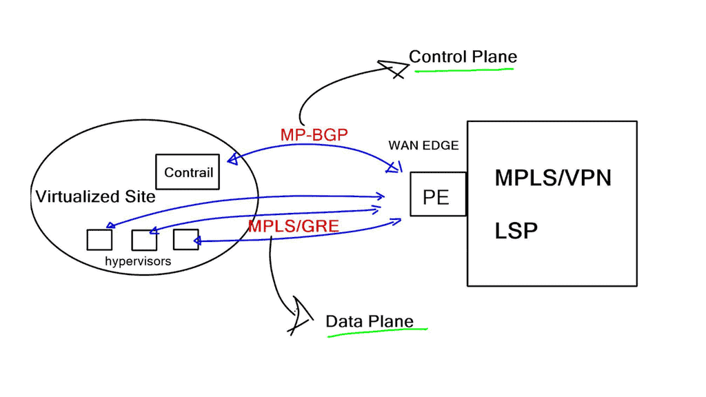
Junipers OpenContrail can connect virtual networks to external Layer 3 MPLS VPN for WAN integration. In addition, they gave the controller the ability to peer BGP to gateway routers. For the data plane, they support MPLS-over-GRE, and for the control plane, they speak MP-BGP.

Contrail communicates directly with PE routers, exchanging VPNv4 routes with MP-BGP and using MPLS-over-GRE encapsulation to pass IP traffic between hypervisor hosts and PE routers. Using standards-based protocols lets you choose any hardware appliance as the gateway node.

mpls overaly

This data and control plane makes integration to an MPLS/VPN backbone a simple task. First, MP-BGP between the controllers and PE-routers should be established. Inter-AS Option B next hop self-approach should be used to demonstrate some demarcation points.

OpenContrail has emerged as a game-changer in software-defined networking, empowering organizations to build agile, secure, and scalable networks in the cloud era. With its advanced features, such as network virtualization, secure multi-tenancy, intelligent automation, and scalability, OpenContrail offers a comprehensive solution that addresses the complex networking challenges of modern cloud environments.

As the demand for efficient and flexible network management continues to rise, OpenContrail provides a compelling option for organizations looking to optimize their network infrastructure and unlock the full potential of the cloud.

Summary: OpenContrail

OpenContrail is a powerful open-source software-defined networking (SDN) solution revolutionizing network management and connectivity. In this blog post, we will explore its key features, benefits, and use cases and showcase how it empowers organizations to build robust and scalable networks.

Understanding OpenContrail

OpenContrail, developed by Juniper Networks, is an open-source SDN controller that provides network virtualization and automation capabilities. It is a single control point for managing and orchestrating network resources, enabling organizations to simplify network operations and enhance flexibility. By decoupling the network control plane from the underlying physical infrastructure, OpenContrail brings agility and scalability to modern networks.

Key Features of OpenContrail

OpenContrail offers a wide range of features, making it a preferred choice for network administrators. Some notable features include:

1. Virtual Network Overlay: OpenContrail creates virtual network overlays, allowing multiple virtual networks to coexist on a shared physical infrastructure. This isolation ensures enhanced security and enables efficient resource utilization.

2. Policy-Driven Automation: With policy-driven automation, network administrators can define and enforce network policies and access controls across the infrastructure. OpenContrail simplifies the management and enforcement of complex policies, reducing operational overhead.

3. Analytics and Monitoring: OpenContrail provides extensive analytics and monitoring capabilities, offering real-time insights into network traffic, performance, and security. These insights help administrators optimize network resources and troubleshoot issues effectively.

Use Cases of OpenContrail

OpenContrail finds applications in various use cases across industries. Some prominent use cases include:

1. Cloud Infrastructure: OpenContrail enables cloud service providers to build and manage scalable and secure cloud infrastructures. It facilitates seamless integration with popular cloud platforms and offers rich networking capabilities.

2. Data Centers: OpenContrail simplifies network management in data center environments. It provides dynamic workload placement, automated provisioning, and seamless connectivity between virtual machines and containers, ensuring efficient resource utilization.

3. Multi-Cloud Networking: OpenContrail supports multi-cloud networking, allowing organizations to connect and manage multiple cloud environments securely. It provides seamless connectivity, consistent policies, and centralized control across cloud providers.

Conclusion:

OpenContrail presents a game-changing solution for organizations seeking to enhance their networking capabilities. With its rich feature set, including virtual network overlays, policy-driven automation, and advanced analytics, OpenContrail empowers organizations to build scalable, secure, and agile networks. Whether it’s cloud infrastructure, data centers, or multi-cloud networking, OpenContrail is a reliable and versatile SDN solution.

rsz_overlay_soltuins

Overlay Virtual Networking | Overlay Virtual Networks

Overlay Virtual Networks

In today's interconnected world, networks enable seamless communication and data transfer. Overlay virtual networking has emerged as a revolutionary approach to network connectivity, offering enhanced flexibility, scalability, and security. This blog post aims to delve into the concept of overlay virtual networking, exploring its benefits, use cases, and potential implications for modern network architectures.

Overlay virtual networking is a network virtualization technique that decouples the logical network from the underlying physical infrastructure. It creates a virtual network on top of the existing physical infrastructure, enabling the coexistence of multiple logical networks on the same physical infrastructure. By abstracting the network functions and services from the physical infrastructure, overlay virtual networking provides a flexible and scalable solution for managing complex network environments.

Scalability and Flexibility: Overlay virtual networks provide the ability to scale network resources on-demand without disrupting the underlying physical infrastructure. This enables organizations to expand their network capabilities swiftly and efficiently, catering to changing business requirements.

Enhanced Security: Overlay virtual networks offer heightened security by isolating traffic and providing secure communication channels. By segmenting the network into multiple virtual domains, potential threats can be contained, preventing unauthorized access to sensitive data.

Cloud Computing: Overlay virtual networks are extensively used in cloud computing environments. They allow multiple tenants to have their own isolated virtual networks, ensuring data privacy and security. Additionally, overlay networks enable seamless migration of virtual machines between physical hosts, enhancing resource utilization.

Software-Defined Networking (SDN): Overlay virtual networks align perfectly with the principles of Software-Defined Networking. By abstracting the logical network from the physical infrastructure, SDN controllers can dynamically manage and provision network resources, optimizing performance and efficiency.

Overlay virtual networks have emerged as a powerful networking solution, providing scalability, flexibility, and enhanced security. Their applications span across various domains, including cloud computing and software-defined networking. As technology continues to evolve, overlay virtual networks are poised to play a vital role in shaping the future of networking.

Highlights: Overlay Virtual Networks

Overlay Network Architecture:

Overlay virtual networks are built on the existing physical network infrastructure, creating a logical network layer that operates independently. This architecture allows organizations to leverage the benefits of virtualization without disrupting their underlying network infrastructure.

The virtual network overlay software is at the heart of an overlay virtual network. This software handles the encapsulation and decapsulation of network packets, enabling communication between virtual machines (VMs) or containers across different physical hosts or data centers. It ensures data flows seamlessly within the overlay network, regardless of the underlying network topology.

To fully comprehend overlay virtual network architecture, it is crucial to understand its key components. These include:

1. Virtual Network Overlay: The virtual network overlay is the logical representation of a virtual network that operates on top of the physical infrastructure. It encompasses virtual switches, routers, and other network elements facilitating network connectivity.

2. Tunneling Protocols: Tunneling protocols play a vital role in overlay virtual network architecture by encapsulating network packets within other packets. Commonly used tunneling protocols include VXLAN (Virtual Extensible LAN), GRE (Generic Routing Encapsulation), and Geneve.

3. Network Virtualization Software: Network virtualization software is a crucial component that enables virtual network creation, provisioning, and management. It provides a centralized control plane and offers network segmentation, traffic isolation, and policy enforcement features.

### The Mechanics Behind the Magic

Overlay virtual networks function by encapsulating packets of data with additional headers, enabling them to traverse across multiple network segments seamlessly. This encapsulation is crucial as it allows for the creation of virtualized network paths that are independent of the physical network. Technologies like Virtual Extensible LAN (VXLAN) and Generic Network Virtualization Encapsulation (GENEVE) are commonly employed to facilitate this process. These technologies not only enhance the network’s scalability but also improve its ability to adapt to complex network demands.

### Benefits Driving Adoption

The benefits of overlay virtual networks are manifold. First and foremost, they offer unparalleled scalability, allowing organizations to expand their network infrastructure without the need for significant physical overhauls. Additionally, they provide enhanced network segmentation and isolation, which are critical for maintaining data privacy and security in a multi-tenant environment. Furthermore, by decoupling the virtual network from the physical infrastructure, overlay networks enable more agile and responsive network management, which is essential for businesses operating in dynamic digital ecosystems.

**Types of Overlay Networks**

1. Virtual Private Networks (VPNs):

VPNs are one of the most common types of overlay networks. They enable secure communication over public networks by creating an encrypted tunnel between the sender and receiver. Individuals and organizations widely use VPNs to protect sensitive data and maintain privacy. Additionally, they allow users to bypass geographical restrictions and access region-restricted content.

2. Software-Defined Networks (SDNs):

In network architecture, SDNs utilize overlay networks to separate the control plane from the data plane. SDNs provide centralized management, flexibility, and scalability by decoupling network control and forwarding functions. Overlay networks in SDNs enable the creation of virtual networks on top of the physical infrastructure, allowing for more efficient resource allocation and dynamic network provisioning.

3. Peer-to-Peer (P2P) Networks:

P2P overlay networks are decentralized systems that facilitate direct communication and file sharing between nodes without relying on a central server. They leverage overlay networks to establish direct connections between peers and enable efficient data distribution. These networks are widely used for content sharing, real-time streaming, and decentralized applications.

4. Content Delivery Networks (CDNs):

CDNs employ overlay networks to optimize content delivery by strategically distributing content across multiple servers in different geographic regions. By bringing content closer to end-users, CDNs reduce latency and improve performance. Overlay networks in CDNs enable efficient content caching, load balancing, and fault tolerance, resulting in faster and more reliable content delivery.

5. Overlay Multicast Networks:

Overlay multicast networks are designed to distribute data to multiple recipients simultaneously efficiently. These networks use overlay protocols to construct multicast trees and deliver data over these trees. Overlay multicast networks benefit applications such as video streaming, online gaming, and live events broadcasting, where data must be transmitted to many recipients in real-time.

Google Cloud CDN

**What is Google Cloud CDN?**

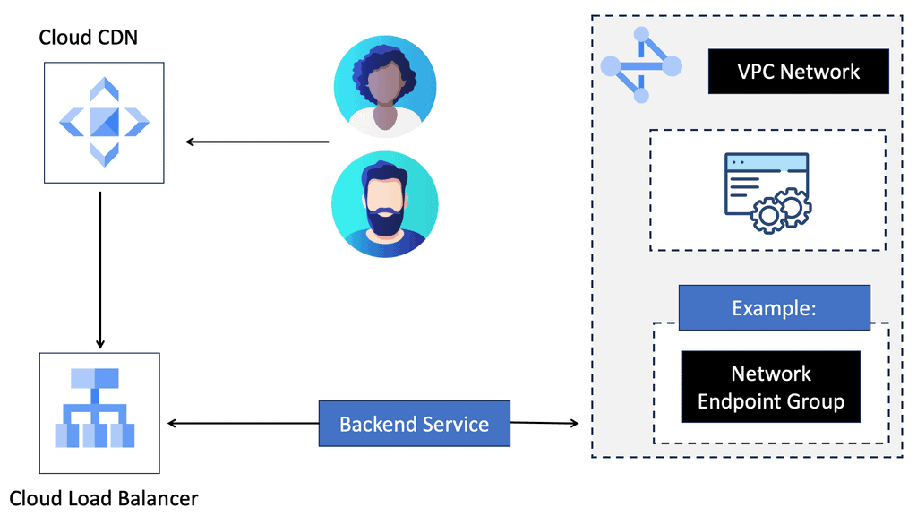
Google Cloud CDN is a globally distributed network of servers designed to cache and deliver content closer to the end-users, reducing latency and improving load times. By leveraging Google’s robust infrastructure, Cloud CDN allows businesses to serve their content quickly and reliably to users all over the world. This service is particularly beneficial for websites, APIs, and applications that experience high traffic or need to operate at peak performance levels.

**Key Features of Google Cloud CDN**

One of the standout features of Google Cloud CDN is its integration with Google Cloud’s services. This seamless connection means you can easily manage your CDN alongside other Google Cloud products, streamlining operations. Additionally, Google Cloud CDN offers features like SSL/TLS support, advanced caching capabilities, and custom domain support, ensuring secure and flexible content delivery.

Another crucial feature is the global reach of Google Cloud CDN. With points of presence (PoPs) strategically located around the world, content is delivered from the nearest server to the user, ensuring quick and reliable access. The network is designed to handle high volumes of traffic, making it ideal for businesses of any size.

**Benefits of Using Google Cloud CDN**

The benefits of adopting Google Cloud CDN are manifold. Firstly, it significantly reduces latency, ensuring that users have a smooth and fast experience. This is particularly vital for businesses that rely on web traffic to drive sales or engagement. Faster load times can lead to increased user satisfaction and higher conversion rates.

Secondly, Google Cloud CDN enhances security. By offloading traffic to edge servers, it acts as a protective layer against DDoS attacks, mitigating threats before they reach your core infrastructure. This added security is invaluable for businesses that handle sensitive data or rely on uptime for operational success.

Lastly, Google Cloud CDN offers cost efficiency. By using caching and strategically distributing content, it reduces the need for expensive bandwidth and server resources. This optimization can lead to significant cost savings, making it an attractive option for businesses looking to maximize their cloud investment.

**How to Get Started with Google Cloud CDN**

Getting started with Google Cloud CDN is straightforward. First, you’ll need to set up a Google Cloud account if you don’t already have one. Once your account is ready, you can enable Cloud CDN through the Google Cloud Console. From there, you can configure your caching rules, secure your content with SSL/TLS, and monitor performance with Google Cloud’s comprehensive analytics tools.

To ensure optimal performance, it’s advisable to familiarize yourself with best practices for content caching and delivery. Google Cloud provides extensive documentation and support to help you make the most out of their CDN service.

Use Cases of Overlay Virtual Networking:

1. Multi-Tenancy: Overlay virtual networking provides an ideal solution for organizations to segregate their network resources securely. By creating virtual overlays, multiple tenants can coexist on a single physical network infrastructure without interference. This enables service providers and enterprises to offer distinct network environments to customers or departments while ensuring isolation and security.

2. Data Center Interconnect: Overlay virtual networking enables efficient and scalable data center interconnect (DCI). With traditional networking, interconnecting multiple data centers across geographies can be complex and costly. However, overlay virtual networking simplifies this process by abstracting the underlying physical infrastructure and providing a unified logical network. It allows organizations to seamlessly extend their networks across multiple data centers, enhancing workload mobility and disaster recovery capabilities.

3. Cloud Computing: Cloud computing heavily relies on overlay virtual networking to deliver agility and scalability. Cloud providers can dynamically provision and manage network resources by leveraging overlay networks, ensuring optimal customer performance and flexibility. Overlay virtual networking enables the creation of virtual networks that are isolated from each other, allowing for secure and efficient multi-tenant cloud environments.

4. Microservices and Containerization: The rise of microservices architecture and containerization has presented new networking challenges. Overlay virtual networking provides a solution by enabling seamless communication between microservices and containers, regardless of their physical location. It ensures that applications and services can communicate with each other, even across different hosts or clusters, without complex network configurations.

5. Network Segmentation and Security: Overlay virtual networking enables granular network segmentation, allowing organizations to implement fine-grained security policies. By creating overlay networks, administrators can isolate different workloads, departments, or applications, ensuring each segment has dedicated network resources and security policies. This enhances security by limiting the lateral movement of threats and reducing the attack surface.

Tunneling Protocols

Tunneling protocols play a crucial role in overlay virtual networks by facilitating the encapsulation and transportation of network packets over the underlying physical network. Popular tunneling protocols such as VXLAN (Virtual Extensible LAN), MPLS (Multiprotocol Label Switching ), NVGRE (Network Virtualization using Generic Routing Encapsulation), and Geneve provide the necessary mechanisms for creating virtual tunnels and encapsulating traffic.

The Network Virtualization Edge (NVE) acts as the endpoint for the overlay virtual network. It connects the physical network infrastructure to the virtual network, ensuring seamless communication between the two. NVEs perform functions like encapsulation, decapsulation, and mapping virtual network identifiers (VNIs) to the appropriate virtual machines or containers.

Example: Point-to-Point GRE 

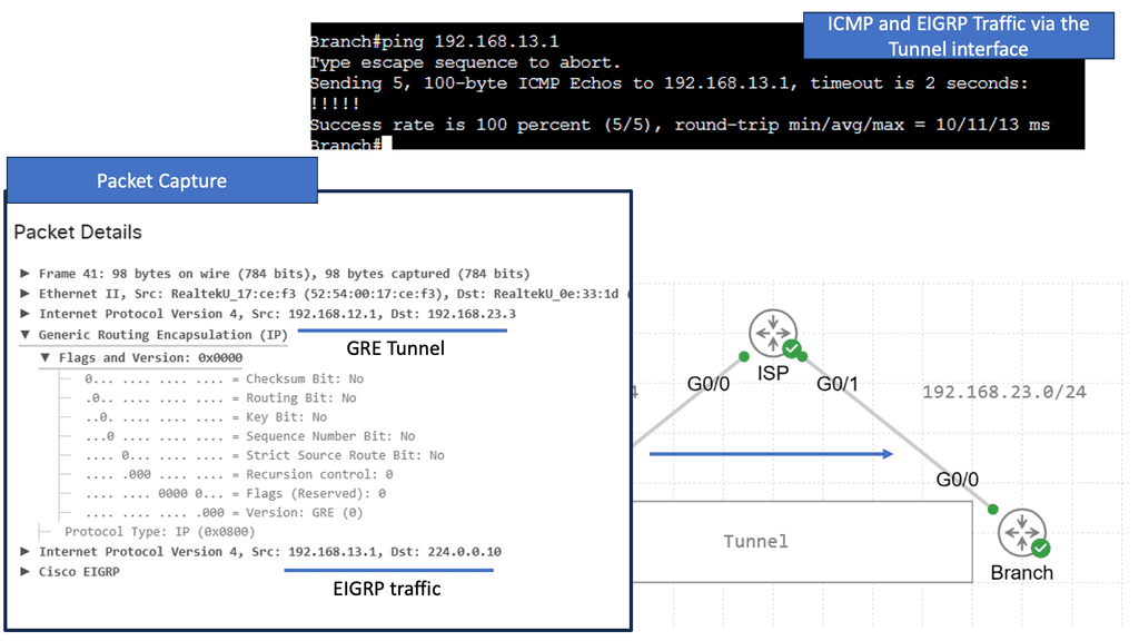
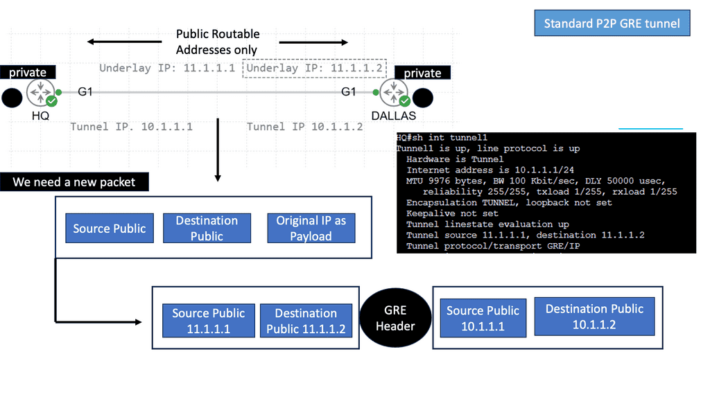
GRE, or Generic Routing Encapsulation, is a tunneling protocol widely used in overlay networks. It encapsulates various network layer protocols within IP packets, enabling virtual point-to-point connections over an existing IP network. GRE provides a mechanism to extend private IP addressing schemes over public networks, facilitating secure and efficient communication between remote locations.GRE without IPsec

Example: GRE and IPSec

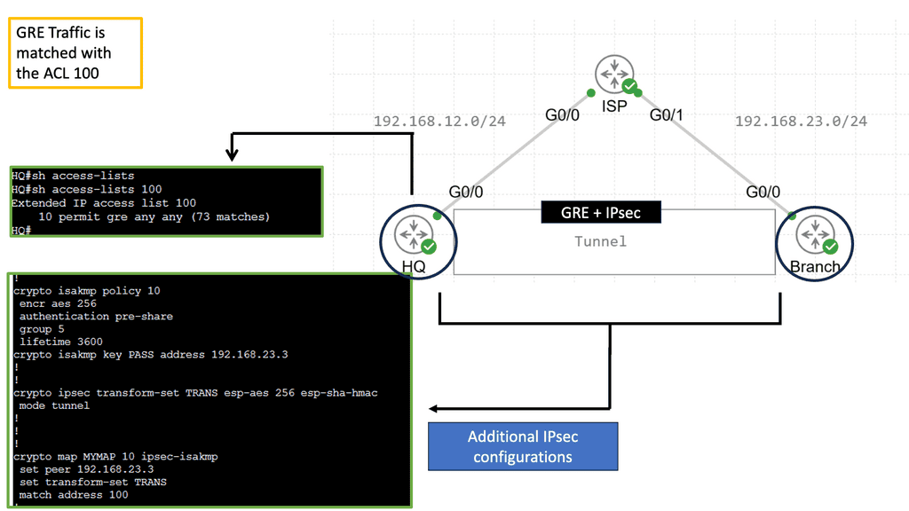
GRE and IPSEC often work together to create secure tunnels across public networks. GRE provides the means for encapsulating and carrying different protocols, while IPSEC ensures the confidentiality and integrity of the encapsulated packets. By combining the strengths of both protocols, organizations can establish secure connections that protect sensitive data and enable secure communication between remote networks.

The combination of GRE and IPSEC offers several benefits and finds applications in various scenarios. Some of the key advantages include enhanced security, scalability, and flexibility. Organizations can utilize this technology to establish secure site-to-site VPNs, remote access VPNs, and even to facilitate secure multicast communication. Whether connecting branch offices, enabling remote employee access, or safeguarding critical data transfers, GRE and IPSEC are indispensable tools.

GRE with IPsec

Example: MPLS Overlay Tunneling

MPLS overlay tunneling is a technique that enables the creation of virtual private networks (VPNs) over existing network infrastructures. It involves encapsulating data packets within additional headers to establish tunnels between network nodes. MPLS, or Multiprotocol Label Switching, is a versatile technique that facilitates the forwarding of network packets. It operates at the OSI (Open Systems Interconnection) model’s layer 2.5, combining the benefits of both circuit-switching and packet-switching technologies. By assigning labels to data packets, MPLS enables efficient routing and forwarding, enhancing network performance.

**Overlay Network Control Plane**

The control plane in an overlay virtual network manages and maintains the overall network connectivity. It handles tasks such as route distribution, network mapping, and keeping the overlay network’s forwarding tables. Border Gateway Protocol (BGP) and Virtual Extensible LAN Segment Identifier (VXLAN VNI) provide the necessary control plane mechanisms. The network can adapt to changing conditions and optimize performance through centralized or distributed control plane architectures.

Components of the Overlay Network Control Plane

a) Controller: The controller serves as the core component of the control plane, acting as a centralized entity that orchestrates network operations. It receives information from network devices, processes it, and then disseminates instructions to ensure proper network functioning.

b) Routing Protocols: Overlay networks employ various routing protocols to determine the optimal paths for data transmission. Protocols like BGP, OSPF, and IS-IS are commonly used to establish and maintain routes within the overlay network.

c) Virtual Network Mapping: This component maps virtual network topologies onto the physical infrastructure. It ensures that virtual network elements are appropriately placed and interconnected, optimizing resource utilization while maintaining network performance.

Underlay and Clos Fabric

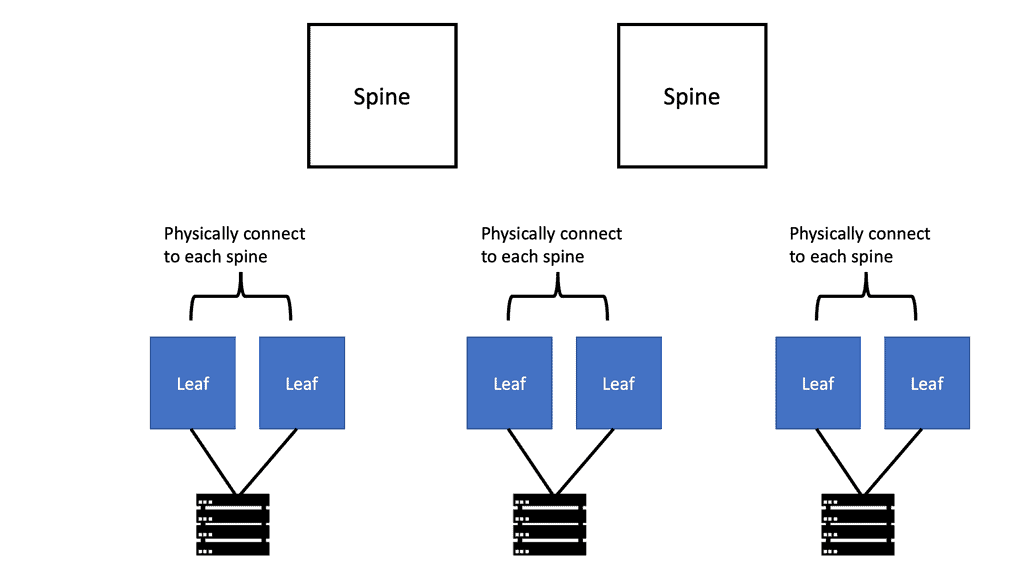
The underlay of most modern data centers is a 3-stage or 5-stage Clos fabric, with the physical infrastructure and point-to-point Layer 3 interfaces between the spines and leaves. Network virtualization can be created by elevating the endpoints and applications connected to the network into this overlay, thus logically carving out different services on top of it.

Traditional data center network architectures, such as the three-tier architecture, were widely used. These architectures featured core, distribution, and access layers, each serving a specific purpose. However, as data traffic increased and workloads became more demanding, these architectures started to show limitations in terms of scalability and performance.

Introducing Leaf and Spine Architecture

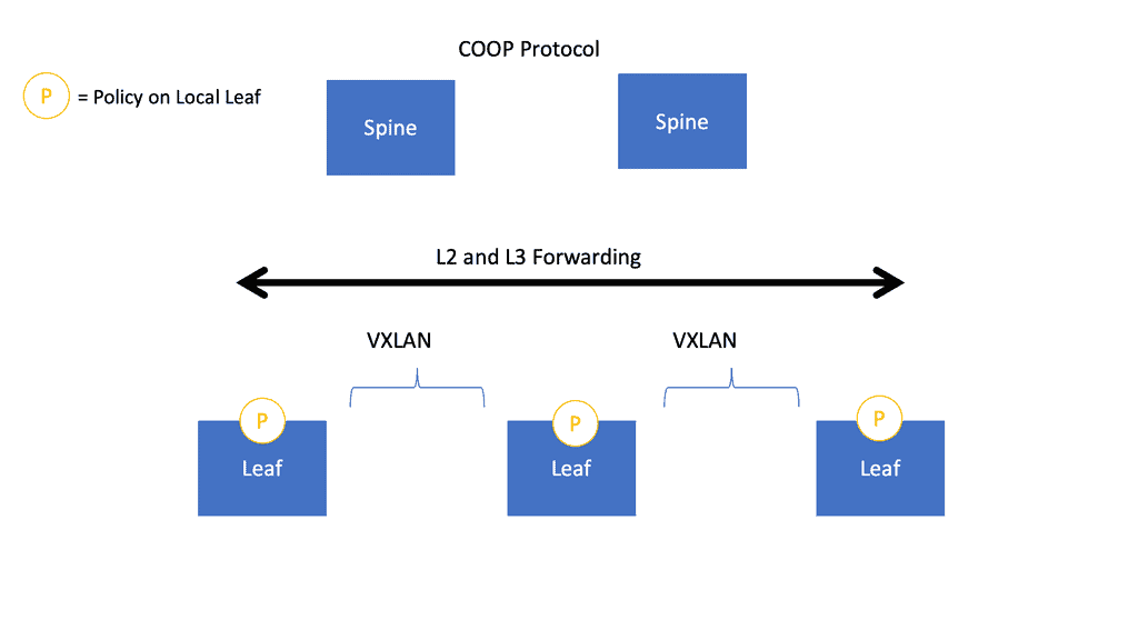
Leaf and spine architecture emerged as a solution to overcome the shortcomings of traditional network architectures. This modern approach reimagines network connectivity by establishing a fabric of interconnected switches. The leaf switches act as access switches, while the spine switches provide high-speed interconnectivity between the leaf switches. This design increases scalability, reduces latency, and improves bandwidth utilization.

Network overlay

VXLAN and Leaf and Spine

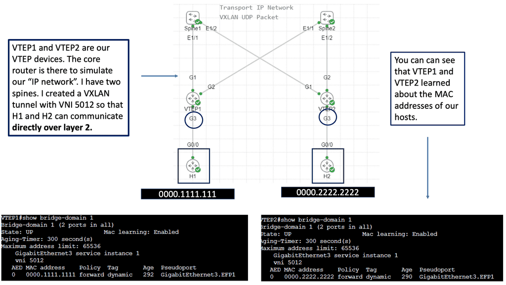
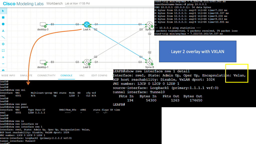
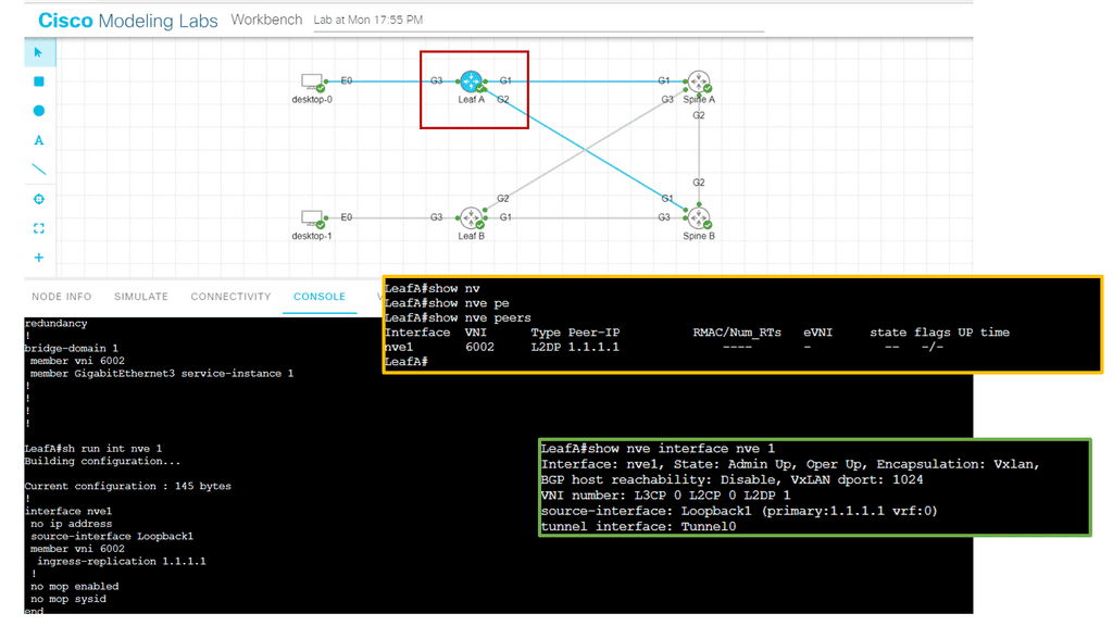
In RFC 7348, a Virtual Extensible LAN (VXLAN) is a data plane encapsulation type capable of supporting Layer 2 and Layer 3 payloads. In addition to logically separating broadcast or bridging domains in a network, virtual LANs (VLANs) are limited in their scalability to 4K VLANs. By contrast, VXLAN provides a 24-bit VXLAN Network Identifier (VNI) in the VXLAN header, allowing the network administrator more flexibility to partition the network logically.

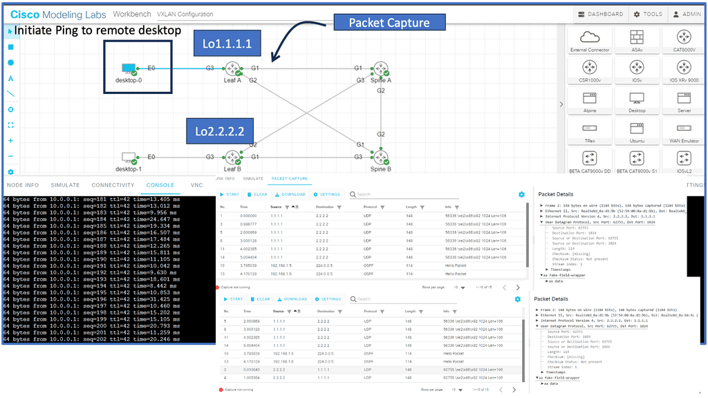
VXLAN is, in essence, a stateless tunnel originating at one endpoint and terminating at another because of its encapsulating trait. The VXLAN Tunnel Endpoints (VTEPs) are the endpoints that encapsulate and decapsulate the VXLAN tunnel. The first thing you need to understand about VXLAN is that these tunnels can originate and terminate on network devices or servers with the help of a virtual switch such as Open vSwitch, with a VXLAN module that is usually accelerated by hardware so that the CPU doesn’t have to process these packets in software.

Example: VXLAN Flood and Learn

Understanding VXLAN Flood and Learn

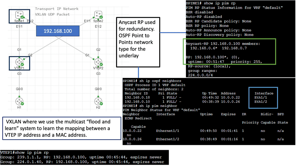
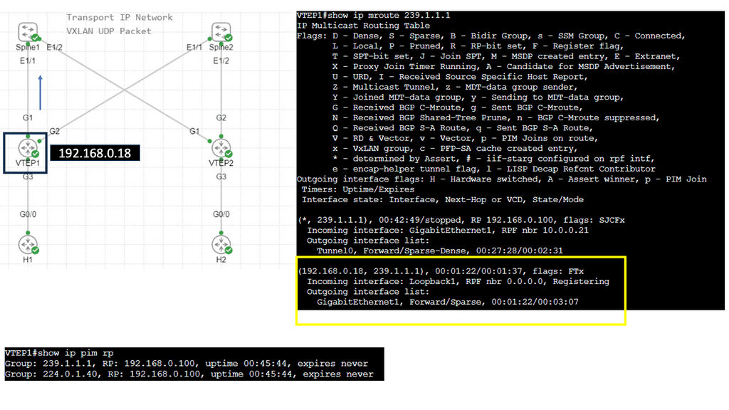
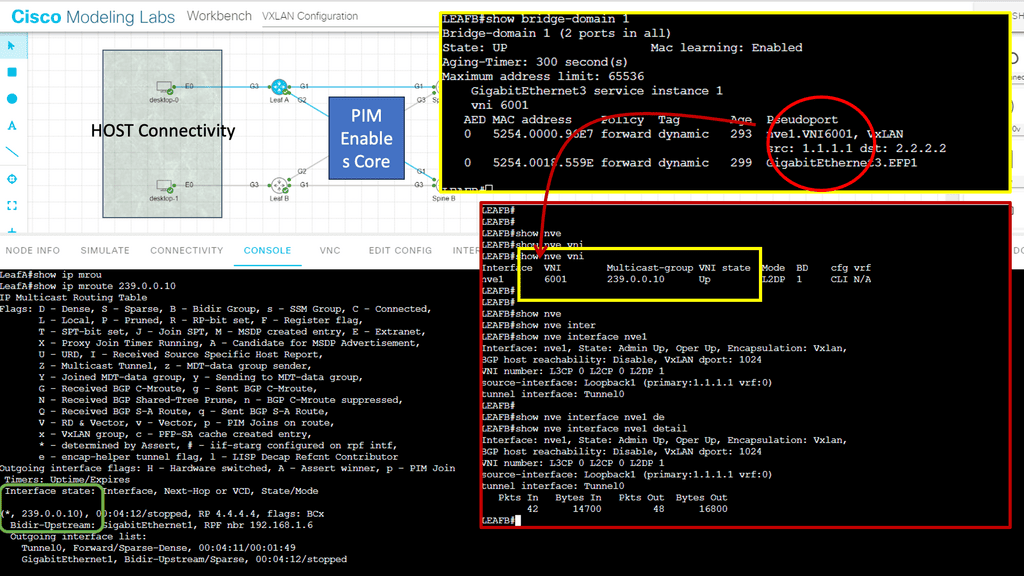
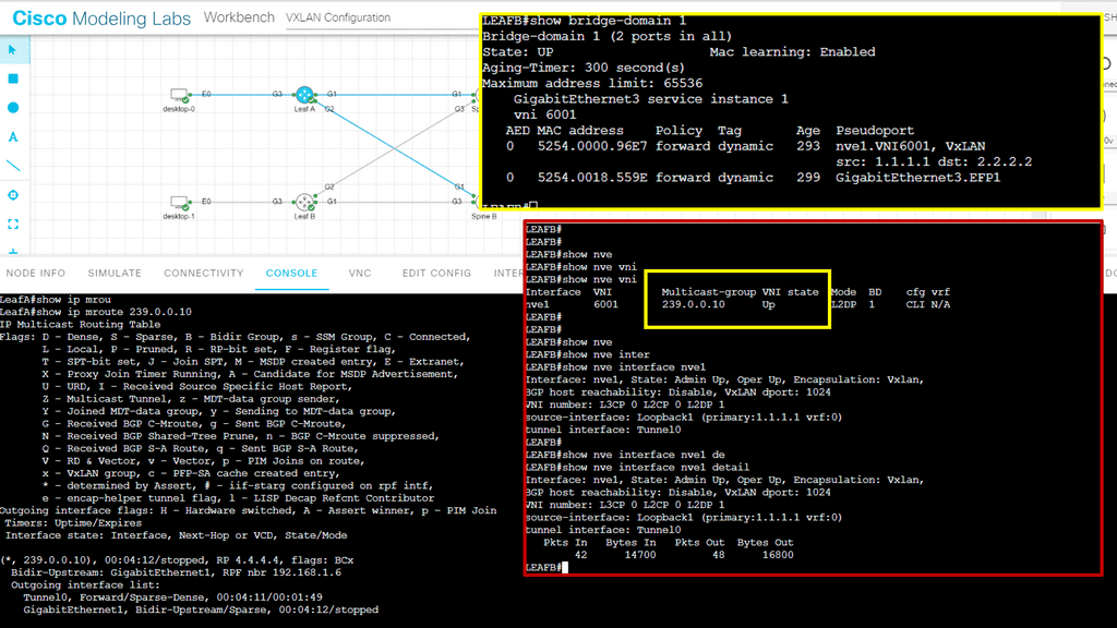
VXLAN Flood and Learn is a mechanism used in VXLAN networks to facilitate the dynamic learning of MAC addresses in a scalable manner. Traditionally, MAC learning relied on control-plane protocols, which could become a bottleneck in larger deployments. With VXLAN Flood and Learn, the burden of MAC address learning is offloaded to the data plane, allowing for greater scalability and efficiency.

Multicast plays a pivotal role in VXLAN Flood and Learn. It serves to transmit broadcast, unknown unicast, and multicast (BUM) traffic within the VXLAN overlay. By utilizing multicast, BUM traffic can be efficiently delivered to interested recipients across the VXLAN fabric, eliminating the need for flooding at Layer 2.

Adopting VXLAN Flood and Learn with Multicast brings several advantages to network operators. Firstly, it reduces the reliance on control-plane protocols, simplifying the network architecture and improving scalability. Additionally, it minimizes unnecessary traffic across the VXLAN fabric, resulting in enhanced efficiency. However, it’s essential to consider the scalability of the multicast infrastructure and the impact of multicast traffic on the underlying network.

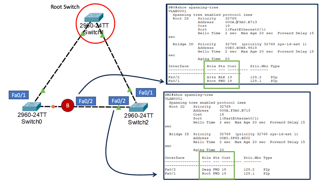
**VXLAN vs. Spanning Tree Protocol**

Now, let’s compare VXLAN and STP across various aspects:

Scalability: VXLAN provides unparalleled scalability by enabling the creation of up to 16 million logical networks, addressing the limitations of traditional VLANs. In contrast, STP suffers from scalability issues due to its limited VLAN range and the potential for network loops.

Efficiency: VXLAN optimizes network utilization by allowing traffic to be load-balanced across multiple paths, resulting in improved performance. STP, on the other hand, blocks redundant paths, leading to underutilization of available network resources.

Convergence Time: VXLAN exhibits faster convergence time compared to STP. With VXLAN, network reconfigurations can be achieved dynamically without service interruption, while STP requires considerable time for convergence, causing potential service disruptions.

stp port states

Multicast Overlay

VXLAN encapsulates Ethernet frames within UDP packets, allowing virtual machines (VMs) to communicate across different physical networks or data centers seamlessly. When combined, multicast and VXLAN offer a robust solution for scaling network virtualization environments. Multicast efficiently distributes traffic across VXLAN tunnels, ensuring optimal delivery to multiple hosts. By leveraging multicast, VXLAN eliminates the need for unnecessary packet replication, reducing network congestion and enhancing overall performance.

VXLAN multicast mode

Advantages of Overlay Virtual Networks

Enhanced Security and Isolation:

One key advantage of overlay virtual networks is their ability to provide enhanced security and isolation. Encapsulating traffic within virtual tunnels allows overlay networks to establish secure communication channels between network segments. This isolation prevents unauthorized access and minimizes the potential for network breaches.

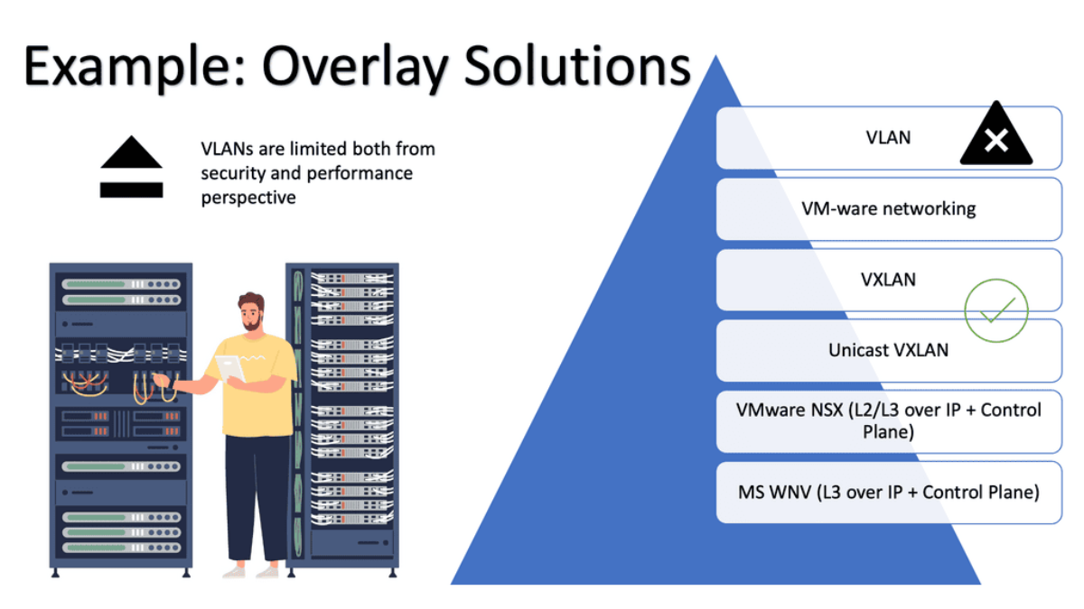
While VLANs offer flexibility and ease of network management, one of their significant disadvantages lies in their limited scalability. As networks expand and the number of VLANs increases, managing and maintaining the VLAN configurations becomes increasingly complex. Network administrators must carefully plan and allocate resources to prevent scalability issues and potential performance bottlenecks.

Simplified Network Management

Overlay virtual networks simplify network management. By decoupling the virtual network from the physical infrastructure, network administrators can easily configure and manage network policies and routing without affecting the underlying physical network. This abstraction layer streamlines network management tasks, resulting in increased operational efficiency.

Scalability and Flexibility

Scalability is a critical requirement in modern networks, and overlay virtual networks excel in this aspect. By leveraging the virtualization capabilities, overlay networks can dynamically allocate network resources based on demand. This flexibility enables seamless scaling of network services, accommodating evolving business needs and ensuring optimal network performance.

Performance Optimization

Overlay virtual networks also offer performance optimization features. By implementing intelligent traffic engineering techniques, overlay networks can intelligently route traffic and optimize network paths. This ensures efficient utilization of network resources and minimizes latency, resulting in improved application performance.

Advanced Topics

1. GETVPN:

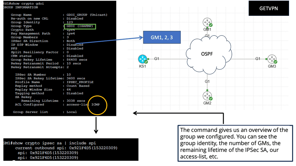
Group Encrypted Transport VPN (GET VPN) is a set of Cisco IOS features that secure IP multicast group and unicast traffic over a private WAN. GET VPN secures IP multicast or unicast traffic by combining the keying protocol Group Domain of Interpretation (GDOI) with IP security (IPsec) encryption. With GET VPN, multicast and unicast traffic are protected without the need for tunnels, as nontunneled (that is, “native”) IP packets can be encrypted.

Key Components of Getvpn

GDOI Key Server: The GDOI Key Server is the central authority for key management in Getvpn. It distributes encryption keys to all participating network devices, ensuring secure communication. By centrally managing the keys, the GDOI Key Server simplifies adding or removing devices from the network.

Group Member: The Group Member is any device that is part of the Getvpn network. It can be a router, switch, or firewall. Group Members securely receive encryption keys from the GDOI Key Server and encrypt/decrypt traffic using these keys. This component ensures that data transmitted within the Getvpn network remains confidential and protected.

Group Domain of Interpretation (GDOI): The GDOI protocol is the backbone of Getvpn. It enables secure exchange and management between the GDOI Key Server and Group Members. Using IPsec for encryption and the Internet Key Exchange (IKE) protocol for key establishment, GDOI ensures the integrity and confidentiality of data transmitted over the Getvpn network.

2. DMVPN

DMVPN is a scalable and flexible networking solution that allows the creation of secure virtual private networks over a public infrastructure. Unlike traditional VPNs, DMVPN dynamically builds tunnels between network endpoints, providing a more efficient and cost-effective approach to network connectivity.

The underlay network forms the foundation of DMVPN. It represents the physical infrastructure that carries IP traffic between different sites. This network can be based on various technologies, such as MPLS, the Internet, or even a mix of both. It provides the necessary connectivity and routing capabilities to establish communication paths between the DMVPN sites.

While the underlay takes care of the physical connectivity, the overlay network is where DMVPN truly shines. This layer is built on top of the underlay and is responsible for creating a secure and efficient virtual network. Through the magic of tunneling protocols like GRE (Generic Routing Encapsulation) or IPsec (Internet Protocol Security), DMVPN overlays virtual tunnels over the underlay network, enabling seamless communication between sites.

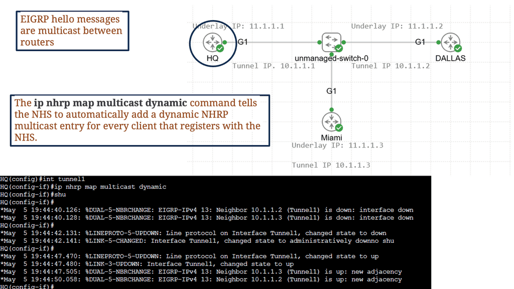
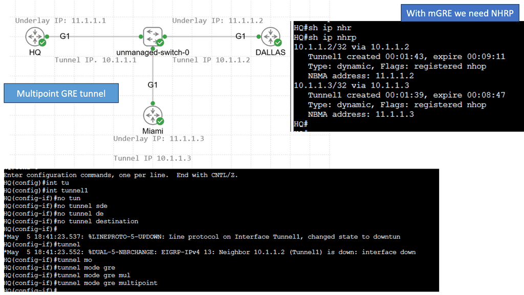
1. Multipoint GRE Tunnels: One key component of DMVPN is the multipoint GRE (mGRE) tunnels. These tunnels allow multiple sites to communicate with each other over a shared IP network. Using a single tunnel interface makes scaling the network easier and reduces administrative overhead.

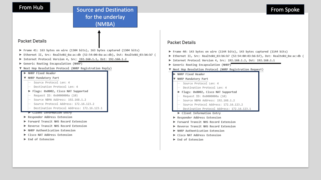
2. Next-Hop Resolution Protocol (NHRP): NHRP is another essential component of DMVPN. It allows mapping the tunnel IP address to the remote site’s physical IP address. This dynamic mapping allows efficient routing and eliminates the need for static or complex routing protocols.

3. IPsec Encryption: To ensure secure communication over the public network, DMVPN utilizes IPsec encryption. IPsec encrypts the data packets traveling between sites, making it nearly impossible for unauthorized entities to intercept or tamper with the data. This encryption provides confidentiality and integrity to the network traffic.

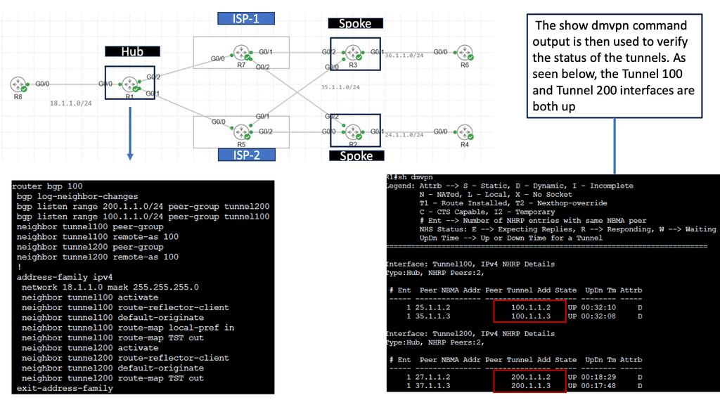
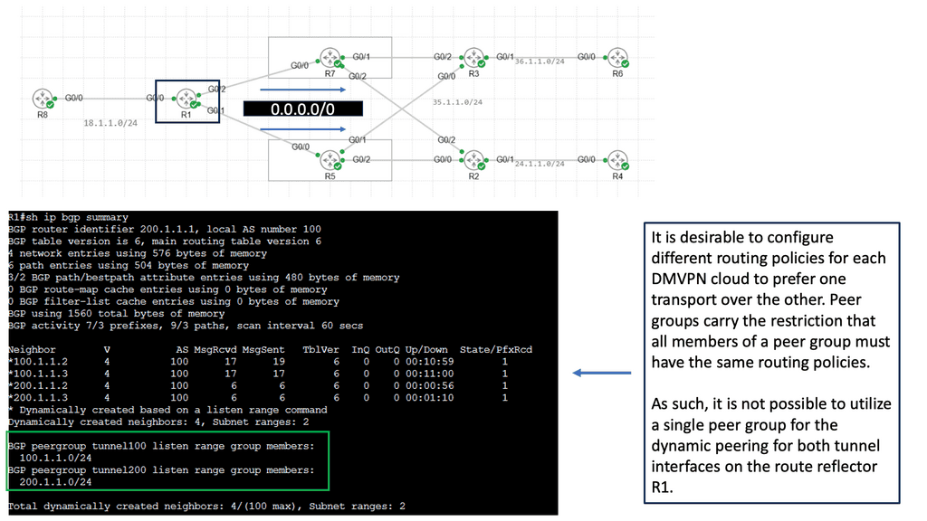
The Single Hub Dual Cloud Architecture

The single-hub dual cloud architecture takes the benefits of DMVPN to the next level. With this configuration, a central hub site is a connection point for multiple cloud service providers (CSPs). This architecture enables businesses to leverage the strengths of different CSPs simultaneously, ensuring high availability and redundancy.

One key advantage of the single hub dual cloud architecture is improved reliability. By distributing traffic across multiple CSPs, businesses can mitigate the risk of service disruption and minimize downtime. Additionally, this architecture provides enhanced performance by leveraging the geographic proximity of different CSPs to various remote sites.

Implementing the single-hub dual cloud architecture requires careful planning and consideration. Factors such as CSP selection, network design, and security measures must all be considered. It is crucial to assess your organization’s specific requirements and work closely with network engineers and CSP providers to ensure a smooth and successful deployment.

**DMVPN vs GETVPN**

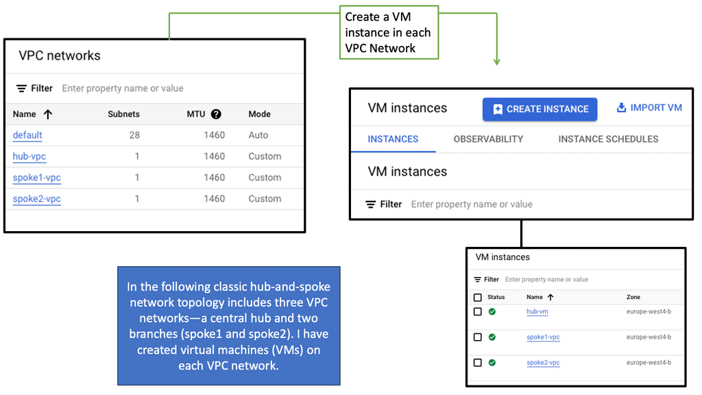
DMVPN and GETVPN are two VPN technologies commonly used in Enterprise WAN setups, especially when connecting many remote sites to one hub. Both GETVPN and DMVPN technologies allow hub-to-spoke and spoke-to-spoke communication. Whenever any of these VPN solutions are deployed, especially on Cisco Routers, a security license is an additional overhead (cost).

Tunnel-less VPN technology, GETVPN, provides end-to-end security for network traffic across fully mesh topologies. DMVPN enables full mesh connectivity with a simple hub-and-spoke configuration. In DMVPN, IPsec tunnels are formed over dynamically/statically addressed spokes.

3. MPLS VPN

At its core, MPLS VPN is a technique that utilizes MPLS labels to route data securely over a shared network infrastructure. It enables the creation of virtual private networks, allowing businesses to establish private and isolated communication channels between their various sites. By leveraging MPLS technology, MPLS VPN ensures optimal performance, service quality, and enhanced data transmission security.

MPLS VPN Components

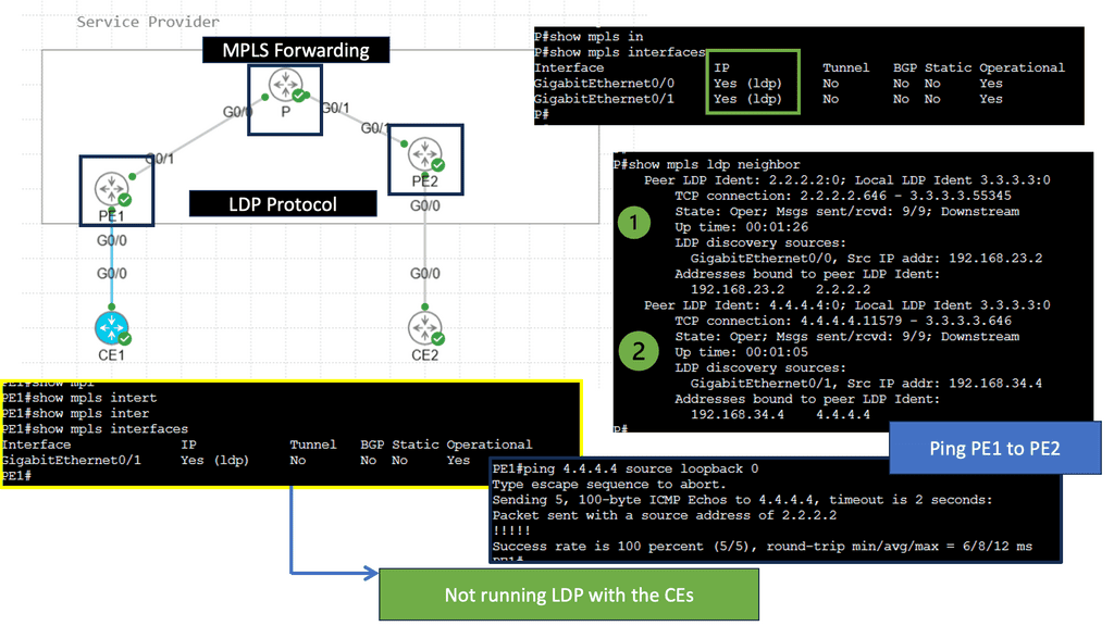
1. Provider Edge (PE) Routers: PE routers are located at the edge of the service provider’s network. They act as the entry and exit points for the customer’s data traffic. PE routers are responsible for applying labels to incoming packets and forwarding them based on the predetermined VPN routes.

2. Customer Edge (CE) Routers: CE routers are located at the customer’s premises and connect the customer’s local network to the service provider’s MPLS VPN network. They establish a secure connection with the PE routers and exchange routing information to ensure proper data forwarding.

3. Provider (P) Routers: P routers are the backbone of the service provider’s network. They form the core network and forward labeled packets between the PE routers. P routers do not participate in VPN-specific functions and only focus on efficient packet forwarding.

**Label Distribution Protocol (LDP)**

LDP is a key component of MPLS VPNs. It distributes labels across the network, ensuring each router has the necessary information to label and forward packets correctly. LDP establishes label-switched paths (LSPs) between PE routers, providing the foundation for efficient data transmission.

**Virtual Routing and Forwarding (VRF)**

VRF is a technology that enables the creation of multiple virtual routing tables within a single physical router. Each VRF instance represents a separate VPN, allowing for isolation and secure communication between different customer networks. VRF ensures that data from one VPN does not mix with another, providing enhanced privacy and security.

Use Case: Understanding Performance-Based Routing

Performance-based routing is a dynamic approach to network routing that considers real-time metrics such as latency, packet loss, and available bandwidth to determine the most optimal path for data transmission. Unlike traditional static routing protocols that rely on predetermined routes, performance-based routing adapts to the ever-changing network conditions, ensuring faster and more reliable data delivery.

Enhanced Network Performance: By leveraging performance-based routing algorithms, businesses can significantly improve network performance. This approach’s dynamic nature allows for intelligent decision-making, routing data through the most efficient paths, and avoiding congested or unreliable connections. This results in reduced latency, improved throughput, and enhanced us.

Cost Savings: Performance-based routing not only improves network performance but also leads to cost savings. Businesses can minimize bandwidth consumption by optimizing data transmission paths, effectively reducing operational expenses. Additionally, organizations can make more efficient use of their network infrastructure by avoiding underperforming or expensive routes.

Related: Before you proceed, you may find the following useful:

  1. SD-WAN Overlay
  2. Open Networking
  3. Segment Routing
  4. SDN Data Center
  5. Network Overlays
  6. Virtual Switch
  7. Load Balancing
  8. OpenContrail
  9. What is BGP Protocol in Networking

Overlay Virtual Networks

Concept of network virtualization

It’s worth mentioning that network virtualization is nothing new. The most common forms of network virtualization are virtual LANs (VLANs), virtual private networks (VPNs), and Multiprotocol Label Switching (MPLS). VLAN has been the first to extract the location of Layer 2 connectivity across multiple Layer 2 switches. VPN enables overlay networks across untrusted networks such as the WAN, while MPLS segments traffic based on labels.

These technologies enable the administrators to physically separate endpoints into logical groups, making them behave like they are all on the same local (physical) segment. The ability to do this allows for much greater efficiency in traffic control, security, and network management.

    • Enhanced Connectivity:

One of the primary advantages of network overlay is its ability to enhance connectivity. By creating a virtual network layer, overlay networks enable seamless communication between devices and applications, irrespective of their physical location.

This means organizations can effortlessly connect geographically dispersed branches, data centers, and cloud environments, fostering collaboration and resource sharing. Moreover, network overlays offer greater flexibility by allowing organizations to dynamically adjust and optimize their network configurations to meet evolving business needs.

    • Improved Scalability:

Traditional network infrastructures often struggle to keep up with the increasing demands of modern applications and services. Network overlay addresses this challenge by providing a scalable solution. By decoupling the virtual network from the physical infrastructure, overlay networks allow for more efficient resource utilization and easier scaling.
Organizations can easily add or remove network elements without disrupting the entire network. As a result, network overlays enable organizations to scale their networks rapidly and cost-effectively, ensuring optimal performance even during peak usage periods.

Tailored load balancing

Some customers may not require cloud load balancing services provided by the cloud services if they have optimized web delivery by deploying something like Squid or NGINX. Squid is a caching proxy that improves web request response times by caching frequently requested web pages. NGINX ( open source reverse proxy ) is used to load balance Hypertext Transfer Protocol ( HTTP ) among multiple servers.

Example: Traffic flow and the need for a virtual overlay

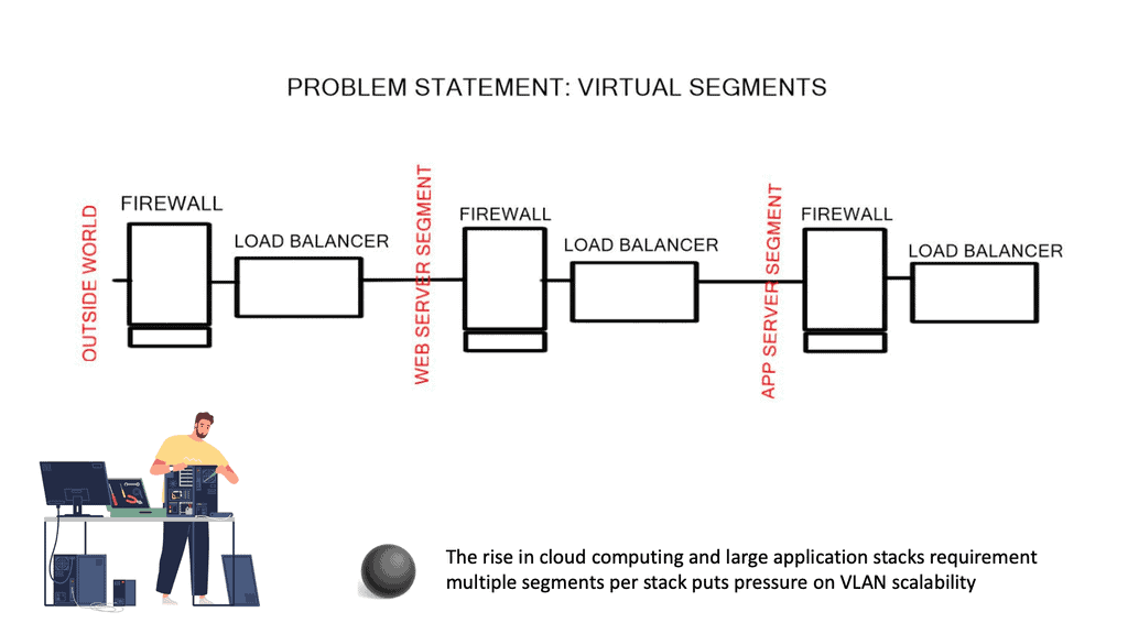
Traffic would flow to Web servers and trigger application and database requests. Each tier requires different segments, and in large environments, the limitations of using VLANs to create these segments will bring both scalability and performance problems.

This is why we need virtual overlay solutions. These subnets require Layer 3 and sometimes Layer 2 ( MAC ). Layer 2 connectivity might be for high availability services that rely on gratuitous Address Resolution Protocol ( ARP ) between devices or some other non-routable packet that can not communicate over IP. If the packet is not Layer 3 routable, it needs to communicate via Layer 2 VLANs.

Virtual overlay networking
Diagram: Virtual overlay networking and complex application tiers.

Scalability and Security Concerns

The weakest link in a security paradigm is the lowest application in that segment. Make each application an independent tenant so all other applications are unaffected if a security breach or misuse occurs in one application stack.

Designers should always attempt to design application stacks to minimize beachheading, i.e., an attacker compromising one box and using it to jump to another quickly. Public and private clouds should support multi-tenancy with each application stack.

However, scalability issues arise when you deploy each application as an individual segment. For example, customer X’s cloud application requires four segments; 4000 VLANs soon become 1000 applications. Media Access Control ( MAC ) visibility has an entire reach throughout Layer 2 domains.

Some switches support a low count number of MAC addresses. When a switch reaches its MAC limit, it starts flooding packets, increasing network load and consuming available bandwidth that should be used for production services.

…current broadcast domains can support … around 1,000 end hosts in a single bridged LAN of 100 bridges” (RFC 5556 – TRILL)

NIC in promiscuous mode and failure domains

Server administrators configure server NICs in promiscuous mode to save configuration time. NICs in promiscuous mode look at all frames passing even when the frame is not destined for them. Network cards acting in promiscuous mode are essentially the same as having one VLAN spanning the entire domain. Sniffer products set promiscuous modes to capture all data on a link and usually only act in this mode for troubleshooting purposes.

A well-known issue with Layer 2 networks is that they present a single failure domain with extreme scalability and operational challenges. This is related to Layer 2 Spanning Tree Protocol ( STP ); THRILL is also susceptible to broadcast storms and network meltdowns.

The rise of overlay virtual networks

Previously discussed scalability and operational concerns force vendors to develop new data center technologies. One of the most prevalent new technologies is overlay virtual networks, tunneling over IP. An overlay is a tunnel between two endpoints, allowing frames to be transported. The beauty of overlay architectures is that they enable switch table sizes not to increase as the number of hosts attached increases.

Vendors’ Answer: Virtual Overlay Solutions

Diagram: Virtual overlay solutions.

Virtual Overlay Solution: Keep complexity to the edges.

Ideally, we should run virtual networks over IP like SKYPE runs Voice over IP. The recommended design retains complexity at the network’s edge; the IP transport network provides IP transport. A transport network does not need to be a Layer 2 network and can have as many IP subnets and router hops.

All data ( storage, vMotion, user traffic ) traffic becomes an IP application. The concept resembles how Border Gateway Protocol ( BGP ) applies to TCP. End hosts carry out encapsulation and use the network for transport. Again, complexity is at the edge, similar to the Internet. Keeping complexity to the edge makes Layer 3 fabrics efficient and scalable.

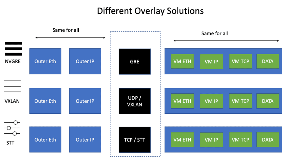
VXLAN, STT, and ( NV ) GRE

Numerous encapsulation methods can tunnel over the IP core. This is known as virtual overlay networking and includes VXLAN, STT, and ( NV ) GRE. The main difference between these technologies is the encapsulation method and minor technological differences with TCP offload and load balancing.

virtual overlay solutions
Diagram: Virtual overlay solution.

The Recommended Design: Leaf and Spine.

Like the ACI network, virtual overlay networks work best with Leaf and Spine fabric architectures. Leaf and Spine designs guarantee any two endpoints get equal bandwidth. VMs on the same Top-of-Rack ( ToR ) switch will have access to more bandwidth than if the VM had to communicate across the Spine layer.

Overlay networks assume that the underlying network has a central endpoint. The transport network should avoid oversubscription as much as possible. If security concerns you, you can always place similar VM appliances on dedicated clusters, one type per physical server.

( NV ) GRE, VXLAN, and STT do not have an built-in security features meaning the transport network MUST be secure.

TCP offload, load balancing & scale-out NAT

TCP can push huge segments down the physical NIC and slice the packet into individual TCP segments, improving TCP performance. For example, you can push 10Gbps from a VM with TCP offload. The problem is that NICs only support VLANs and not VXLANs.

NICIRA added another header in front of TCP segments. TCP is embedded in another TCP. Now, you can use the existing NIC to slice the current TCP segment into smaller TCP segments. It is dramatically improving performance.

STT and VXAN

STT and VXAN can use 5-tuple load balancing as they use port numbers. Therefore, traffic sent between a pair of VMs can use more than one link in the network. Unfortunately, not many switches can load balance based on the GRE payload used by NVGRE.

Scale-out NAT is difficult to implement as an asymmetric path is not guaranteed. Furthermore, the shared state is tied to an outside IP address, which limits scale-out options. To scale out effectively, the state has to be spread across all members of the NAT cluster. The new approach uses floating public IP addresses and one-to-one mapping between floating IP and the private IP address inside—there is no state due to the one-to-one mapping.

Distributed layer 2 & layer 3 forwarding  

They distributed Layer 2 forwarding ( data plane ): Most Overlays offer distributed Layer 2 forwarding. VM can be sent to VM in the same segment. The big question is how they distribute MAC to VTEP – some use multicast and traditional Ethernet flooding, while others use control planes. The big question is how scalable is the control plane.

Distributed Layer 3 forwarding ( data plane ): On the other hand, if you have multiple IP subnets between segments ( not layer 2 ), you need to forward between them. The inter-subnet must not be a choke point. If your data center has lots of intra-traffic ( East to West traffic), avoid centralized inter-subnet forwarding, which will quickly become a traffic choke point.

The router will process ARP if you are doing Layer 3 forwarding. But if you are doing a mix of Layer 2 and 3, make sure you can reduce the flooding by intercepting ARP requests and caching ARP replies, known as distributed ARP Caching.

**Scale-out control plane** 

Initial overlays used multicast and Ethernet-like learning. Now, some vendors are using controller-based overlays. Keep in mind that the controller can now become a scalability bottleneck. However, many vendors, such as Cisco ACI, can scale the controllers and have a quorum.

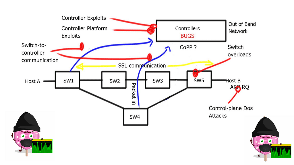
Efficient controller scalability is seen when controllers do not participate in the data plane ( do not reply to ARP ). This type of controller scales better than controllers that intercept data plane packets and perform data plane activity. So, the data plane will not be affected if a controller is offline. In the early days of Sofware-Defined Networking, this was not the case. If the controller was down, the network was down.

Scale-out controllers 

Attempt to design scale-out controllers by building a cluster of controllers and having some protocol running between them. You now have clear failure domains. For example, controller A looks after VM segment A and Controller B, and control looks after VM segment B. For cloud deployments in multiple locations, deploy multiple controller clusters in each location.

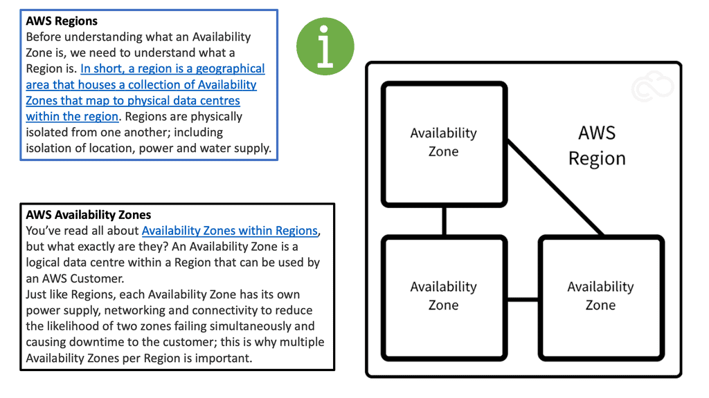
Availability zones

Design availability zones with hierarchical failure domains by splitting infrastructures into regions. Problems arising in one region do not affect all other regions. You have one or more availability zones within an area for physical and logical isolation.

Availability zones limit the impact of a failure in a failure domain. An example of a failure domain could be a VLAN experiencing a broadcast storm. Attempt to determine the span of VLANs across availability zones—define VLANs to one-ToR switch. Never stretch VLANs as you create a single failure domain by merging two zones.

Do not stretch a VLAN across multiple availability zones. This is why we have network overlays in the first place, so we don’t need to stretch VLAN across the data center. For example, VXLAN uses the VNI to differentiate between Layer 2 and Layer 3 traffic over a routed underlay. We can use VXLAN as the overlay network to span large Layer 2 domains over a routed core.

Availability zones
Diagram: Availability zones. The source is cloudconstruct.

Network Overlay Controllers

As a final note on controllers, controller-based SDN networks participate in data planes and perform activities such as MAC learning and ARP replies. As mentioned, this is not common nowadays but was at the start of the SDN days. If the controller performs activities such as MAC learning and APR replies and the controller fails, then you have network failure.

The more involved the controller is in the forwarding decisions, the worse the outage can be. All overlay networking vendors nowadays have controllers that set up the control plane so the data plane can forward traffic without getting involved in data plane activity. This design also allows the controller to be scaled without affecting the data plane activity.

Closing Point: Overlay Virtual Networks

Overlay virtual networking is a method where a virtual network is built on top of an existing physical network. This abstraction allows for greater flexibility in managing and deploying network resources. By decoupling the physical infrastructure from the network’s logical topology, businesses can create complex network architectures without the need to reconfigure physical hardware. This is particularly advantageous in environments like data centers, where dynamic and scalable network configurations are essential.

The primary advantage of overlay virtual networking lies in its ability to simplify and streamline network management. With overlays, network administrators can easily create, modify, and manage network segments without altering the underlying physical infrastructure. Additionally, overlay networks provide enhanced security through network segmentation, allowing for isolated virtual networks within the same physical environment. This capability reduces the risk of unauthorized access and data breaches.

Overlay virtual networking is increasingly being adopted in various sectors, including cloud computing, data centers, and enterprise networks. For cloud service providers, overlays enable the rapid deployment of virtual networks for different customers, ensuring that resources are efficiently utilized while maintaining customer privacy. In data centers, overlay networks facilitate the creation of agile and scalable environments to accommodate fluctuating workloads and demands. Enterprises, on the other hand, leverage overlays to integrate multiple branch offices seamlessly into a cohesive network, enhancing communication and collaboration.

While overlay virtual networking offers numerous benefits, it’s not without its challenges. Network administrators must consider factors such as increased complexity in troubleshooting, potential performance issues due to additional encapsulation, and the need for advanced skills to manage and implement overlay technologies effectively. It’s crucial for organizations to weigh these considerations against the benefits to determine the best approach for their specific needs.

Summary: Overlay Virtual Networks

Overlay networking has revolutionized the way we design and manage modern networks. In this blog post, we will delve into the fascinating world of overlay networking, exploring its benefits, applications, and critical components.

Understanding Overlay Networking

Overlay networking is a technique for creating virtual networks on top of an existing physical network infrastructure. By decoupling the network services from the underlying hardware, overlay networks provide flexibility, scalability, and enhanced security.

Benefits of Overlay Networking

One of the primary advantages of overlay networking is its ability to abstract the underlying physical infrastructure, allowing for seamless integration of different network technologies and protocols. This flexibility empowers organizations to adapt to changing network requirements without significant disruptions. Additionally, overlay networks facilitate the implementation of advanced network services, such as virtual private networks (VPNs) and load balancing, while maintaining a simplified management approach.

Applications of Overlay Networking

Overlay networking finds applications in various domains, ranging from data centers to cloud computing. In data center environments, overlay networks enable efficient multi-tenancy, allowing different applications or departments to operate within isolated virtual networks. Moreover, overlay networking facilitates the creation of hybrid cloud architectures, enabling seamless connectivity between on-premises infrastructure and public cloud resources.

Key Components of Overlay Networking

Understanding overlay networking’s key components is crucial to comprehending it. These include overlay protocols, which establish and manage virtual network connections, and software-defined networking (SDN) controllers, which orchestrate the overlay network. Additionally, virtual tunnel endpoints (VTEPs) play a vital role in encapsulating and decapsulating network packets, ensuring efficient communication within the overlay network.

Overlay networking has genuinely transformed the landscape of modern network architectures. By providing flexibility, scalability, and enhanced security, overlay networks have become indispensable in various industries. Whether it is for data centers, cloud environments, or enterprise networks, overlay networking offers a powerful solution to meet the evolving demands of the digital era.

Conclusion:

In conclusion, overlay networking has emerged as a game-changer in the world of networking. Its ability to abstract and virtualize network services brings immense value to organizations, enabling them to adapt quickly, enhance security, and optimize resource utilization. As technology continues to advance, overlay networking will likely play an even more significant role in shaping the future of network architectures.

Green data center with eco friendly electricity usage tiny person concept. Database server technology for file storage hosting with ecological and carbon neutral power source vector illustration.

LISP Hybrid Cloud Use Case

LISP Hybrid Cloud Use Case

In the world of networking, the ability to efficiently manage and scale networks is of paramount importance. This is where LISP networking comes into play. LISP, which stands for Locator/ID Separation Protocol, is a powerful networking technology that offers numerous benefits to network administrators and operators. In this blog post, we will explore the world of LISP networking and its key features and advantages.

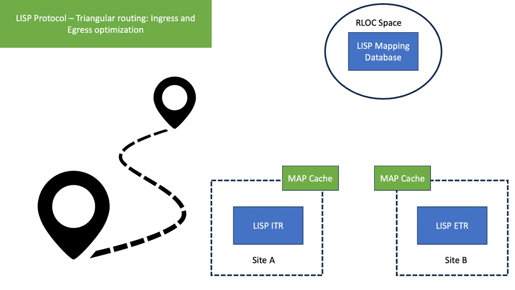
LISP networking is a revolutionary approach to IP addressing and routing that separates the identity of a device (ID) from its location (locator). Traditional IP addressing relies on combining these two aspects, making it challenging to scale networks and manage mobility. LISP overcomes these limitations by decoupling the device's identity and location, enabling more flexible and scalable network architectures.

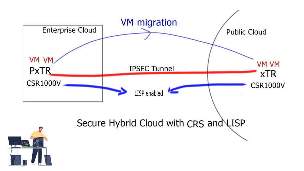
LISP, at its core, is a routing architecture that separates location and identity information for IP addresses. By doing so, it enables scalable and efficient routing across networks. LISP hybrid cloud leverages this architecture to seamlessly integrate multiple cloud environments, including public, private, and on-premises clouds.

Enhanced Scalability: LISP hybrid cloud allows organizations to scale their cloud infrastructure effortlessly. By abstracting location information from IP addresses, it enables efficient traffic routing across cloud environments, ensuring optimal utilization of resources.

Improved Security and Privacy: With LISP hybrid cloud, organizations can establish secure and private connections between different cloud environments. This ensures that sensitive data remains protected while being seamlessly accessed across clouds, bolstering data security and compliance.

Simplified Network Management: By centralizing network policies and control, LISP hybrid cloud simplifies network management for organizations. It provides a unified view of the entire cloud infrastructure, enabling efficient monitoring, troubleshooting, and policy enforcement.

Seamless Data Migration: LISP hybrid cloud enables seamless migration of data between different clouds, eliminating the complexities associated with traditional data migration methods. It allows organizations to transfer large volumes of data quickly and efficiently, minimizing downtime and disruption.

Hybrid Application Deployment: Organizations can leverage LISP hybrid cloud to deploy applications across multiple cloud environments. This enables a flexible and scalable infrastructure, where applications can utilize resources from different clouds based on specific requirements, optimizing performance and cost-efficiency.

The LISP hybrid cloud use case presents a compelling solution for organizations seeking to enhance their cloud infrastructure. With its scalability, security, and simplified network management benefits, LISP hybrid cloud opens up a world of possibilities for seamless integration and optimization of multiple cloud environments. Embracing LISP hybrid cloud can drive efficiency, flexibility, and agility, empowering organizations to stay ahead in today's dynamic digital landscape.

Highlights: LISP Hybrid Cloud Use Case

Understanding LISP

LISP, short for Locator/ID Separation Protocol, is a routing architecture that separates the endpoint identifier (ID) from its location (locator). By doing so, LISP enables efficient routing, scalability, and mobility in IP networks. This protocol has been widely adopted in modern networking to address the challenges posed by the growth of the Internet and the limitations of traditional IP addressing.

Hybrid cloud architecture combines the best of both worlds by integrating public and private cloud environments. It allows organizations to leverage the scalability and cost-effectiveness of public clouds while maintaining control over sensitive data and critical applications in private clouds. This flexible approach provides businesses with the agility to scale their resources up or down based on demand, ensuring optimal performance and cost-efficiency.

The Synergy of LISP and Hybrid Cloud

When LISP and hybrid cloud architecture merge, the result is a powerful combination that offers numerous advantages. LISP’s ability to separate the ID from the locator enables seamless mobility and efficient routing across hybrid cloud environments. By leveraging LISP, organizations can achieve enhanced scalability, simplified network management, and improved performance across their distributed infrastructure.

Highlighting real-world examples of LISP hybrid cloud use cases can shed light on its practical applications. From multinational corporations with geographically dispersed offices to service providers managing cloud-based services, LISP hybrid cloud use cases have demonstrated significant improvements in network performance, reduced latency, simplified network management, and increased overall agility.

Use Case: Hybrid Cloud

The hybrid cloud connects the public cloud provider to the private enterprise cloud. It consists of two or more distinct infrastructures in dispersed locations that remain unique. These unique entities are bound together logically via a network to enable data and application portability. LISP networking performs hybrid cloud and can overcome the negative drawback of stretched VLAN. How do you support intra-subnet traffic patterns among two dispersed cloud locations? Without a stretched VLAN spanning locations, instability may arise from broadcast storms and Layer 2 loops.

Triangular routing

**End to End-to-end connectivity**

Enterprises want the ability to seamlessly insert their application right into the heart of the cloud provider without changing any parameters. Customers want to do this without changing the VM’s IP addresses and MAC addresses. This requires the VLAN to be stretched end-to-end. Unfortunately, IP routing cannot support VLAN extension, which puts pressure on the data center interconnect ( DCI ) link to enable extended VLANs. In reality, and from experience, this is not a good solution.
**LISP Architecture on Cisco Platforms**

There are various Cisco platforms that support LISP, but the platforms are mainly characterized by the operating system software they run. LISP is supported by Cisco’s IOS/IOS-XE, IOS-XR, and NX-OS operating systems. LISP offers several distinctive features and functions, including xTR/MS/MR, IGP Assist, and ESM/ASM Multi-hop. It is not true that all hardware supports all functions or features. Users need to verify that a platform supports key features before implementing it.

IOS-XR and NX-OS do not have distributed architectures, as does Cisco IOS/IOS-XE.RIB and Cisco Express Forwarding (CEF) provide the forwarding architecture for LISP on IOS/IOS-XE platforms using the LISP control process.

Before you proceed, you may find the following helpful:

  1. LISP Protocol
  2. LISP Hybrid Cloud Implementation
  3. Network Stretch
  4. LISP Control Plane
  5. Internet of Things Access Technologies
 

LISP Hybrid Cloud Use Case

The LISP Network

The LISP network comprises a mapping system with a global database of RLOC-EID mapping entries. The mapping system is the control plane of the LISP network decoupled from the data plane. The mapping system is address-family agnostic; the EID can be an IPv4 address mapped to an RLOC IPv6 address and vice versa. Or the EID may be a Virtual Extensible LAN (VXLAN) Layer 2 virtual network identifier (L2VNI) mapped to a VXLAN tunnel endpoint (VTEP) address working as an RLOC IP address.

How Does LISP Networking Work? At its core, LISP networking introduces a new level of indirection between the device’s IP address and location. LISP relies on two key components: the xTR (eXternal Tunnel Router) and the mapping system. The xTR is responsible for encapsulating and forwarding traffic between different LISP sites, while the mapping system stores the mappings between the device’s identity and its current location.

**Benefits of LISP Networking**

Scalability: LISP provides a scalable solution for managing large networks by separating the device’s identity from its location. This allows for efficient routing and reduces the amount of routing table information that needs to be stored and exchanged.

Mobility: LISP networking offers seamless mobility support, enabling devices to change locations without disrupting ongoing communications. This is particularly beneficial in scenarios where mobile devices are constantly moving, such as IoT deployments or mobile networks.

Traffic Engineering: LISP allows network administrators to optimize traffic flow by manipulating the mappings between device IDs and locators. This provides greater control over network traffic and enables efficient load balancing and congestion management.

Security: LISP supports secure communications through the use of cryptographic techniques. It provides authentication and integrity verification mechanisms, ensuring the confidentiality and integrity of data transmitted over the network.

Use Cases for LISP Networking:

A – Data Centers: LISP can significantly simplify the management of large-scale data center networks by providing efficient traffic engineering and seamless mobility support for virtual machines.

B- Internet Service Providers (ISPs): LISP can help ISPs improve their network scalability and handle the increasing demand for IP addresses. It enables ISPs to optimize their routing tables and efficiently manage address space.

C- IoT Deployments: LISP’s mobility support and scalability make it an ideal choice for IoT deployments. It efficiently manages large devices and enables seamless connectivity as devices move across different networks.

LISP Networking and Stretched VLAN

Locator Identity Separation Protocol ( LISP ) can extend subnets without the VLAN. I am creating a LISP Hybrid Cloud. A subnet extension with LISP is far more appealing than a Layer 2 LAN extension. The LISP-enabled hybrid cloud solution allows Intra-subnet communication regardless of where the server is. This means you can have two servers in different locations, one in the public cloud and the other in the Enterprise domain; both servers can communicate as if they were on the same subnet.

LISP acts as an overlay technology

LISP operates like an overlay technology; it encapsulates the source packet with UDP and a header consisting of the source and destination RLOC ( RLOC are used to map EIDS). The result is that you can address the servers in the cloud according to your addressing scheme. There is no need to match your addressing scheme to the cloud addressing scheme.

LISP on the Cloud Service Router ( CRS ) 1000V ( virtual router ) solution provides a Layer-3-based approach to a hybrid cloud. It allows you to stretch subnets from the enterprise to the public cloud without needing a Layer 2 LAN extension.

LISP networking
LISP networking and hybrid cloud

LISP networking deployment key points:

  1. LISP can be deployed with the CRS 1000V in the cloud and either a CRS 1000V or ASR 1000 in the enterprise domain.
  2. The enterprise CRS must have at least two interfaces. One interface is the L3 routed interface to the core. The second interface is a Layer 2 interface to support VLAN connectivity for the servers that require mobility.
  3. The enterprise CRS does not need to be the default gateway, and its interaction with the local infrastructure ( via the Layer 2 interface ) is based on Proxy-ARP. As a result, ARP packets must be allowed on the underlying networks.
  4. The Cloud CRS is also deployed with at least two interfaces. One interface is facing the Internet or MPLS network. The second interface faces the local infrastructure, either by VLANs or Virtual Extensible LAN ( VXLAN ).
  5. The CRS offers machine-level high availability and supports all the VMware high-availability features such as dynamic resource scheduling ( DRS ), vMotion, NIC load balancing, and teaming.
Hybrid Cloud
Hybrid cloud and CRS1000V
  1. LISP is a network-based solution and is independent of the hypervisor. You can have different hypervisors in the Enterprise and the public cloud. No changes to virtual servers or hosts. It’s completely transparent.
  2. The PxTR ( also used to forward to non-LISP sites ) is deployed in the enterprise cloud, and the xTR is deployed in the public cloud.
  3. The CRS1000V deployed in the public cloud is secured by an IPSEC tunnel. Therefore, the LISP tunnel should be encrypted using IPSEC tunnel mode. Tunnel mode is preferred to support NAT.
  4. Each CRS must have one unique outside IP address. This is used to form the IPSEC tunnel between the two endpoints.
  5. Dynamic or static Routing must be enabled over the IPSEC tunnel. This is to announce the RLOC IP address used by the LISP mapping system.
  6. The map-resolver ( MR ) and map server ( MS ) can be enabled on the xTR in the Enterprise or the xTR in the cloud.
  7. Traffic symmetry is still required when you have stateful devices in the path.

 LISP stretched subnets

The two modes of LISP operation are the LISP “Across” subnet and the LISP “Extended” subnet mode. Neither of these modes is used with the LISP-enabled CRS hybrid cloud deployment scenario. The mode of operation utilized is called the LISP stretched subnet model ( SSM ). The same subnet is used on both sides of the network, and mobility is performed between these two segments on the same subnet. You may think that this is the same as LISP “Extended” subnet mode, but in this case, we are not using a LAN extension between sites. Instead, the extended mode requires a LAN extension such as OTV.

LISP stretched subnets

Closing Points on LISP Hybrid Cloud

LISP, or Locator/ID Separation Protocol, is a novel architecture that aims to improve the scalability and manageability of IP networks. By decoupling the location and identity of network devices, LISP enables more efficient routing and simplifies network management. This separation allows for seamless integration between different cloud environments, making it an ideal choice for hybrid cloud implementations. In a LISP-enabled network, endpoints have two addresses: an Endpoint Identifier (EID) that identifies the device and a Routing Locator (RLOC) that identifies its location in the network.

1. **Enhanced Scalability**: One of the key advantages of using LISP in a hybrid cloud setup is its ability to scale effortlessly. By separating identity and location, LISP reduces the complexity of routing tables, allowing networks to grow without the traditional limitations.

2. **Improved Security**: Security is a paramount concern for any cloud implementation. LISP provides improved security features by enabling network segmentation and facilitating the creation of secure communication tunnels between different cloud environments.

3. **Seamless Mobility**: LISP’s architecture supports seamless mobility, which is crucial for hybrid cloud environments where workloads may move between on-premises and cloud-based resources. This mobility ensures minimal disruption and consistent performance.

To successfully implement LISP in a hybrid cloud environment, organizations should follow a structured approach:

1. **Assessment and Planning**: Begin by assessing your current network infrastructure and identifying areas where LISP can bring the most value. Develop a detailed implementation plan that outlines the steps, resources, and timelines required.

2. **Deployment**: Deploy LISP-enabled routers and configure them to support both EIDs and RLOCs. Ensure that your network devices are compatible with the LISP protocol and that they are properly configured to handle LISP traffic.

3. **Testing and Optimization**: Conduct thorough testing to ensure that LISP is functioning as expected. Monitor network performance and make necessary adjustments to optimize routing and security.


Summary: LISP Hybrid Cloud Use Case

In the rapidly evolving world of cloud computing, businesses constantly seek innovative solutions to optimize their operations. One such groundbreaking approach is the utilization of LISP (Locator/ID Separation Protocol) in hybrid cloud environments. In this blog post, we explored the fascinating use case of LISP Hybrid Cloud and delved into its benefits, implementation, and potential for revolutionizing the industry.

Understanding LISP Hybrid Cloud

LISP Hybrid Cloud combines the best of two worlds: the scalability and flexibility of public cloud services with the security and control of private cloud infrastructure. By separating the location and identity of network devices, LISP allows for seamless communication between public and private clouds. This breakthrough technology enables businesses to leverage the advantages of both environments and optimize their cloud strategies.

Benefits of LISP Hybrid Cloud

Enhanced Scalability: LISP Hybrid Cloud offers unparalleled scalability by allowing businesses to scale their operations across public and private clouds seamlessly. This ensures that organizations can meet evolving demands without compromising performance or security.

Improved Flexibility: With LISP Hybrid Cloud, businesses can choose the most suitable cloud resources. They can leverage the vast capabilities of public clouds for non-sensitive workloads while keeping critical data and applications secure within their private cloud infrastructure.

Enhanced Security: LISP Hybrid Cloud provides enhanced security by leveraging the inherent advantages of private clouds. Critical data and applications can remain within the organization’s secure network, minimizing the risk of unauthorized access or data breaches.

Implementation of LISP Hybrid Cloud

Implementing LISP Hybrid Cloud involves several key steps. First, organizations must evaluate their cloud requirements and determine the optimal balance between public and private cloud resources. Next, they must deploy the necessary LISP infrastructure, including LISP routers and mapping servers. Finally, businesses must establish secure communication channels between their public and private cloud environments, ensuring seamless data transfer and interconnectivity.

Conclusion:

In conclusion, LISP Hybrid Cloud represents a revolutionary approach to cloud computing. By harnessing the power of LISP, businesses can unlock the potential of hybrid cloud environments, enabling enhanced scalability, improved flexibility, and heightened security. As the cloud landscape continues to evolve, LISP Hybrid Cloud is poised to play a pivotal role in shaping the future of cloud computing.

What is OpenFlow

What is OpenFlow

What is OpenFlow?

In today's rapidly evolving digital landscape, network management and data flow control have become critical for businesses of all sizes. OpenFlow is one technology that has gained significant attention and is transforming how networks are managed. In this blog post, we will delve into the concept of OpenFlow, its advantages, and its implications for network control.

OpenFlow is an open-standard communications protocol that separates the control and data planes in a network architecture. It allows network administrators to have direct control over the behavior of network devices, such as switches and routers, by utilizing a centralized controller.

Traditional network architectures follow a closed model, where network devices make independent decisions on forwarding packets. On the other hand, OpenFlow introduces a centralized control plane that provides a global view of the network and allows administrators to define network policies and rules from a centralized location.

OpenFlow operates by establishing a secure channel between the centralized controller and the network switches. The controller is responsible for managing the flow tables within the switches, defining how traffic should be forwarded based on predefined rules and policies. This separation of control and data planes allows for dynamic network management and facilitates the implementation of innovative network protocols.

One of the key advantages of OpenFlow is its ability to simplify network management. By centralizing control, administrators can easily configure and manage the entire network from a single point of control. This reduces complexity and enhances the scalability of network infrastructure. Additionally, OpenFlow enables network programmability, allowing for the development of custom networking applications and services tailored to specific requirements.

OpenFlow plays a crucial role in network virtualization, as it allows for the creation and management of virtual networks on top of physical infrastructure. By abstracting the underlying network, OpenFlow empowers organizations to optimize resource utilization, improve security, and enhance network performance. It opens doors to dynamic provisioning, isolation, and efficient utilization of network resources.

Highlights: What is OpenFlow?

How does OpenFlow work?

1: OpenFlow allows network controllers to determine the path of network packets in a network of switches. There is a difference between switches and controllers. With separate control and forwarding, traffic management can be more sophisticated than access control lists (ACLs) and routing protocols.

2: An OpenFlow protocol allows switches from different vendors, often with proprietary interfaces and scripting languages, to be managed remotely. Software-defined networking (SDN) is considered to be enabled by OpenFlow by its inventors.

3: With OpenFlow, Layer 3 switches can add, modify, and remove packet-matching rules and actions remotely. By doing so, routing decisions can be made periodically or ad hoc by the controller and translated into rules and actions with a configurable lifespan, which are then deployed to the switch’s flow table, where packets are forwarded at wire speed for the duration of the rule.

The Role of OpenFlow Controllers

If the switch cannot match packets, they can be sent to the controller. The controller can modify existing flow table rules or deploy new rules to prevent a structural traffic flow. It may even forward the traffic itself if the switch is instructed to forward packets rather than just their headers.

OpenFlow uses Transport Layer Security (TLS) over Transmission Control Protocol (TCP). Switches wishing to connect should listen on TCP port 6653. In earlier versions of OpenFlow, port 6633 was unofficially used. The protocol is mainly used between switches and controllers.

### Origins of OpenFlow

The inception of OpenFlow can be traced back to the early 2000s when researchers at Stanford University sought to create a more versatile and programmable network architecture. Traditional networking relied heavily on static and proprietary hardware configurations, which limited innovation and adaptability. OpenFlow emerged as a solution to these challenges, offering a standardized protocol that decouples the network control plane from the data plane. This separation allows for centralized control and dynamic adjustment of network traffic, fostering innovation and agility in network design.

### How OpenFlow Works

At its core, the OpenFlow protocol facilitates communication between network devices and a centralized SDN controller. It does this by using a series of flow tables within network switches, which are programmed by the controller. These flow tables dictate how packets should be handled, whether they are forwarded to a destination, dropped, or modified in some way. By leveraging OpenFlow, network administrators can deploy updates, optimize performance, and troubleshoot issues with unprecedented speed and precision, all from a single point of control.

Introducing SDN

Recent changes and requirements have driven networks and network services to become more flexible, virtualization-aware, and API-driven. One major trend affecting the future of networking is software-defined networking ( SDN ). The software-defined architecture aims to extract the entire network into a single switch.

Software-defined networking (SDN) is an evolving technology defined by the Open Networking Foundation ( ONF ). It involves the physical separation of the network control plane from the forwarding plane, where a control plane controls several devices. This differs significantly from traditional IP forwarding that you may have used in the past.

The Core Concepts of SDN

At its heart, Software-Defined Networking decouples the network control plane from the data plane, allowing network administrators to manage network services through abstraction of lower-level functionality. This separation enables centralized network control, which simplifies the management of complex networks. The control plane makes decisions about where traffic is sent, while the data plane forwards traffic to the selected destination. This approach allows for a more flexible, adaptable network infrastructure.

The activities around OpenFlow

Even though OpenFlow has received a lot of industry attention, programmable networks and decoupled control planes (control logic) from data planes have been around for many years. To enhance ATM, Internet, and mobile networks’ openness, extensibility, and programmability, the Open Signaling (OPENING) working group held workshops in 1995. A working group within the Internet Engineering Task Force (IETF) developed GSMP to control label switches based on these ideas. June 2002 marked the official end of this group, and GSMPv3 was published.

What is OpenFlow

Data and control plane

Therefore, SDN separates the data and control plane. The main driving body behind software-defined networking (SDN) is the Open Networking Foundation ( ONF ). Introduced in 2008, the ONF is a non-profit organization that wants to provide an alternative to proprietary solutions that limit flexibility and create vendor lock-in.

The insertion of the ONF allowed its members to run proof of concepts on heterogeneous networking devices without requiring vendors to expose their software’s internal code. This creates a path for an open-source approach to networking and policy-based controllers. 

Knowledge Check: Data & Control Plane

### Data Plane: The Highway for Your Data

The data plane, often referred to as the forwarding plane, is responsible for the actual movement of packets of data from source to destination. Imagine it as a network’s highway, where data travels at high speed. This component operates at the speed of light, handling massive amounts of data with minimal delay. It’s designed to process packets quickly, ensuring that the information arrives where it needs to be without interruption.

### Control Plane: The Brain Behind the Operation

While the data plane acts as the highway, the control plane is the brain that orchestrates the flow of traffic. It makes decisions about routing, managing the network topology, and controlling the data plane’s operations. The control plane uses protocols to determine the best paths for data and to update routing tables as needed. It’s responsible for ensuring that the network operates efficiently, adapting to changes, and maintaining optimal performance.

### Interplay Between Data and Control Planes

The synergy between the data and control planes is what enables modern networks to function effectively. The control plane provides the intelligence and decision-making necessary to guide the data plane. This interaction ensures that data packets take the best possible paths, reducing latency and maximizing throughput. As networks evolve, the lines between these planes may blur, but their distinct roles remain pivotal.

### Real-World Applications and Innovations

The concepts of data and control planes are not just theoretical—they have practical applications in technologies such as Software-Defined Networking (SDN) and Network Function Virtualization (NFV). These innovations allow for greater flexibility and scalability in managing network resources, offering businesses the agility needed to adapt to changing demands.

Building blocks: SDN Environment 

As a fundamental building block of an SDN deployment, the controller, the SDN switch (for example, an OpenFlow switch), and the interfaces are present in the controller to communicate with forwarding devices, generally the southbound interface (OpenFlow) and the northbound interface (the network application interface).

In an SDN, switches function as basic forwarding hardware, accessible via an open interface, with the control logic and algorithms offloaded to controllers. Hybrid (OpenFlow-enabled) and pure (OpenFlow-only) OpenFlow switches are available.

OpenFlow switches rely entirely on a controller for forwarding decisions, without legacy features or onboard control. Hybrid switches support OpenFlow as well, in addition to traditional operation and protocols. Today, hybrid switches are the most common type of commercial switch. A flow table performs packet lookup and forwarding in an OpenFlow switch.

### The Role of the OpenFlow Controller

The OpenFlow controller is the brain of the SDN, orchestrating the flow of data across the network. It communicates with the network devices using the OpenFlow protocol to dictate how packets should be handled. The controller’s primary function is to make decisions on the path data packets should take, ensuring optimal network performance and resource utilization. This centralization of control allows for dynamic network configuration, paving the way for innovative applications and services.

### OpenFlow Switches: The Workhorses of the Network

While the controller is the brain, OpenFlow switches are the workhorses, executing the instructions they receive. These switches operate at the data plane, where they forward packets based on the rules set by the controller. Each switch maintains a flow table that matches incoming packets to particular actions, such as forwarding or dropping the packet. This separation of control and data planes is what sets SDN apart from traditional networking, offering unparalleled flexibility and control.

### Flow Tables: The Heart of OpenFlow Switches

Flow tables are the core component of OpenFlow switches, dictating how packets are handled. Each entry in a flow table consists of match fields, counters, and a set of instructions. Match fields identify the packets that should be affected by the rule, counters track the number of packets and bytes that match the entry, and instructions define the actions to be taken. This modular approach allows for precise traffic management and is essential for implementing advanced network policies.

OpenFlow Table & Routing Tables 

### What is an OpenFlow Flow Table?

OpenFlow is a protocol that allows network controllers to interact with the forwarding plane of network devices like switches and routers. At the heart of OpenFlow is the flow table. This table contains a set of flow entries, each specifying actions to take on packets that match a particular pattern. Unlike traditional routing tables, which rely on predefined paths and protocols, OpenFlow flow tables provide flexibility and programmability, allowing dynamic changes in how packets are handled based on real-time network conditions.

### Understanding Routing Tables

Routing tables are a staple of traditional networking, used by routers to determine the best path for forwarding packets to their final destinations. These tables consist of a list of network destinations, with associated metrics that help in selecting the most efficient route. Routing protocols such as OSPF, BGP, and RIP are employed to maintain and update these tables, ensuring that data flows smoothly across the interconnected web of networks. While reliable, routing tables are less flexible compared to OpenFlow flow tables, as changes in network traffic patterns require updates to routing protocols and configurations.

Example of a Routing Table 

RIP Configuration RIP configuration

### Key Differences Between OpenFlow Flow Table and Routing Table

The primary distinction between OpenFlow flow tables and routing tables lies in their approach to network management. OpenFlow flow tables are dynamic and programmable, allowing for real-time adjustments and fine-grained control over traffic flows. This makes them ideal for environments where network agility and customization are paramount. Conversely, routing tables offer a more static and predictable method of packet forwarding, which can be beneficial in stable networks where consistency and reliability are prioritized.

### Use Cases: When to Use Each

OpenFlow flow tables are particularly advantageous in software-defined networking (SDN) environments, where network administrators need to quickly adapt to changing conditions and optimize traffic flows. They are well-suited for data centers, virtualized networks, and scenarios requiring high levels of automation and scalability. On the other hand, traditional routing tables are best used in established networks with predictable traffic patterns, such as those found in enterprise or service provider settings, where reliability and stability are key.

You may find the following useful for pre-information:

  1. OpenFlow Protocol
  2. Network Traffic Engineering
  3. What is VXLAN
  4. SDN Adoption Report
  5. Virtual Device Context

What is OpenFlow?

What is OpenFlow?

OpenFlow was the first protocol of the Software-Defined Networking (SDN) trend and is the only protocol that allows the decoupling of a network device’s control plane from the data plane. In most straightforward terms, the control plane can be thought of as the brains of a network device. On the other hand, the data plane can be considered hardware or application-specific integrated circuits (ASICs) that perform packet forwarding.

Numerous devices also support running OpenFlow in a hybrid mode, meaning OpenFlow can be deployed on a given port, virtual local area network (VLAN), or even within a regular packet-forwarding pipeline such that if there is not a match in the OpenFlow table, then the existing forwarding tables (MAC, Routing, etc.) are used, making it more analogous to Policy Based Routing (PBR).

What is OpenFlow
Diagram: What is OpenFlow? The source is cable solutions.

What is SDN?

Despite various modifications to the underlying architecture and devices (such as switches, routers, and firewalls), traditional network technologies have existed since the inception of networking. Using a similar approach, frames and packets have been forwarded and routed in a limited manner, resulting in low efficiency and high maintenance costs. Consequently, the architecture and operation of networks need to evolve, resulting in SDN.

By enabling network programmability, SDN promises to simplify network control and management and allow innovation in computer networking. Network engineers configure policies to respond to various network events and application scenarios. They can achieve the desired results by manually converting high-level policies into low-level configuration commands.

Often, minimal tools are available to accomplish these very complex tasks. Controlling network performance and tuning network management are challenging and error-prone tasks.

A modern network architecture consists of a control plane, a data plane, and a management plane; the control and data planes are merged into a machine called Inside the Box. To overcome these limitations, programmable networks have emerged.

How OpenFlow Works:

At the core of OpenFlow is the concept of a flow table, which resides in each OpenFlow-enabled switch. The flow table contains match-action rules defining how incoming packets should be processed and forwarded. The centralized controller determines these rules and communicates using the OpenFlow protocol with the switches.

When a packet arrives at an OpenFlow-enabled switch, it is first matched against the rules in the flow table. If a match is found, the corresponding action is executed, including forwarding the packet, dropping it, or sending it to the controller for further processing. This decoupling of the control and data planes allows for flexible and programmable network management.

What is OpenFlow SDN?

The main goal of SDN is to separate the control and data planes and transfer network intelligence and state to the control plane. These concepts have been exploited by technologies like Routing Control Platform (RCP), Secure Architecture for Network Enterprise (SANE), and, more recently, Ethane.

In addition, there is often a connection between SDN and OpenFlow. The Open Networking Foundation (ONF) is responsible for advancing SDN and standardizing OpenFlow, whose latest version is 1.5.0.

An SDN deployment starts with these building blocks.

For communication with forwarding devices, the controller has the SDN switch (for example, an OpenFlow switch), the SDN controller, and the interfaces. An SDN deployment is based on two basic building blocks: a southbound interface (OpenFlow) and a northbound interface (the network application interface).

As the control logic and algorithms are offloaded to a controller, switches in SDNs may be represented as basic forwarding hardware. Switches that support OpenFlow come in two varieties: pure (OpenFlow-only) and hybrid (OpenFlow-enabled).

Pure OpenFlow switches do not have legacy features or onboard control for forwarding decisions. A hybrid switch can operate with both traditional protocols and OpenFlow. Hybrid switches make up the majority of commercial switches available today. In an OpenFlow switch, a flow table performs packet lookup and forwarding.

OpenFlow reference switch

The OpenFlow protocol and interface allow OpenFlow switches to be accessed as essential forwarding elements. A flow-based SDN architecture like OpenFlow simplifies switching hardware. Still, it may require additional forwarding tables, buffer space, and statistical counters that are difficult to implement in traditional switches with integrated circuits tailored to specific applications.

There are two types of switches in an OpenFlow network: hybrids (which enable OpenFlow) and pores (which only support OpenFlow). OpenFlow is supported by hybrid switches and traditional protocols (L2/L3). OpenFlow switches rely entirely on a controller for forwarding decisions and do not have legacy features or onboard control.

Hybrid switches are the majority of the switches currently available on the market. This link must remain active and secure because OpenFlow switches are controlled over an open interface (through a TCP-based TLS session). OpenFlow is a messaging protocol that defines communication between OpenFlow switches and controllers, which can be viewed as an implementation of SDN-based controller-switch interactions.

Openflow switch
Diagram: OpenFlow switch. The source is cable solution.
Identify the Benefits of OpenFlow

Application-driven routing. Users can control the network paths.

The networks paths.A way to enhance link utilization.

An open solution for VM mobility. No VLAN reliability.

A means to traffic engineer without MPLS.

A solution to build very large Layer 2 networks.

A way to scale Firewalls and Load Balancers.

A way to configure an entire network as a whole as opposed to individual entities.

A way to build your own encryption solution. Off-the-box encryption.
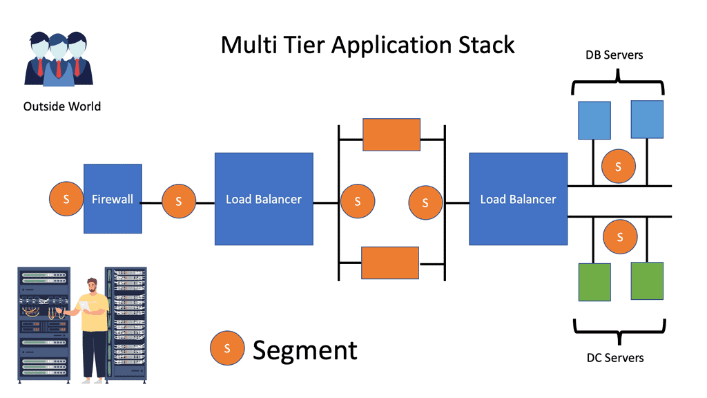
A way to distribute policies from a central controller.

Customized flow forwarding. Based on a variety of bit patterns.

A solution to get a global view of the network and its state. End-to-end visibility.

A solution to use commodity switches in the network. Massive cost savings.

The following table lists the Software Networking ( SDN ) benefits and the problems encountered with existing control plane architecture:

Identify the benefits of OpenFlow and SDN

Problems with the existing approach

Faster software deployment.

Large scale provisioning and orchestration.
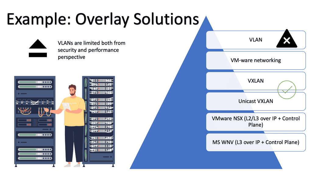
Programmable network elements.

Limited traffic engineering ( MPLS TE is cumbersome )

Faster provisioning.

Synchronized distribution policies.

Centralized intelligence with centralized controllers.

Routing of large elephant flows.

Decisions are based on end-to-end visibility.

Qos and load based forwarding models.

Granular control of flows.

Ability to scale with VLANs.

Decreases the dependence on network appliances like load balancers.

**A key point: The lack of a session layer in the TCP/IP stack**

Regardless of the hype and benefits of SDN, neither OpenFlow nor other SDN technologies address the real problems of the lack of a session layer in the TCP/IP protocol stack. The problem is that the client’s application ( Layer 7 ) connects to the server’s IP address ( Layer 3 ), and if you want to have persistent sessions, the server’s IP address must remain reachable. 

This session’s persistence and the ability to connect to multiple Layer 3 addresses to reach the same device is the job of the OSI session layer. The session layer provides the services for opening, closing, and managing a session between end-user applications. In addition, it allows information from different sources to be correctly combined and synchronized.

The problem is the TCP/IP reference module does not consider a session layer, and there is none in the TCP/IP protocol stack. SDN does not solve this; it gives you different tools to implement today’s kludges.

what is openflow
What is OpenFlow? Lack of a session layer

Control and data plane

When we identify the benefits of OpenFlow, let us first examine traditional networking operations. Traditional networking devices have a control and forwarding plane, depicted in the diagram below. The control plane is responsible for setting up the necessary protocols and controls so the data plane can forward packets, resulting in end-to-end connectivity. These roles are shared on a single device, and the fast packet forwarding ( data path ) and the high-level routing decisions ( control path ) occur on the same device.

What is OpenFlow | SDN separates the data and control plane?

**Control plane**

The control plane is part of the router architecture and is responsible for drawing the network map in routing. When we mention control planes, you usually think about routing protocols, such as OSPF or BGP. But in reality, the control plane protocols perform numerous other functions, including:

Connectivity management ( BFD, CFM )

Interface state management ( PPP, LACP )

Service provisioning ( RSVP for InServ or MPLS TE)

Topology and reachability information exchange ( IP routing protocols, IS-IS in TRILL/SPB )

Adjacent device discovery via HELLO mechanism

ICMP

Control plane protocols run over data plane interfaces to ensure “shared fate” – if the packet forwarding fails, the control plane protocol fails as well.

Most control plane protocols ( BGP, OSPF, BFD ) are not data-driven. A BGP or BFD packet is never sent as a direct response to a data packet. There is a question mark over the validity of ICMP as a control plane protocol. The debate is whether it should be classed in the control or data plane category.

Some ICMP packets are sent as replies to other ICMP packets, and others are triggered by data plane packets, i.e., data-driven. My view is that ICMP is a control plane protocol that is triggered by data plane activity. After all, the “C” is ICMP does stand for “Control.”

**Data plane**

The data path is part of the routing architecture that decides what to do when a packet is received on its inbound interface. It is primarily focused on forwarding packets but also includes the following functions:

ACL logging

 Netflow accounting

NAT session creation

NAT table maintenance

The data forwarding is usually performed in dedicated hardware, while the additional functions ( ACL logging, Netflow accounting ) typically happen on the device CPU, commonly known as “punting.” The data plane for an OpenFlow-enabled network can take a few forms.

However, the most common, even in the commercial offering, is the Open vSwitch, often called the OVS. The Open vSwitch is an open-source implementation of a distributed virtual multilayer switch. It enables a switching stack for virtualization environments while supporting multiple protocols and standards.

Software-defined networking changes the control and data plane architecture.

The concept of SDN separates these two planes, i.e., the control and forwarding planes are decoupled. This allows the networking devices in the forwarding path to focus solely on packet forwarding. An out-of-band network uses a separate controller ( orchestration system ) to set up the policies and controls. Hence, the forwarding plane has the correct information to forward packets efficiently.

In addition, it allows the network control plane to be moved to a centralized controller on a server instead of residing on the same box carrying out the forwarding. Moving the intelligence ( control plane ) of the data plane network devices to a controller enables companies to use low-cost, commodity hardware in the forwarding path. A significant benefit is that SDN separates the data and control plane, enabling new use cases.

A centralized computation and management plane makes more sense than a centralized control plane.

The controller maintains a view of the entire network and communicates with Openflow ( or, in some cases, BGP with BGP SDN ) with the different types of OpenFlow-enabled network boxes. The data path portion remains on the switch, such as the OVS bridge, while the high-level decisions are moved to a separate controller. The data path presents a clean flow table abstraction, and each flow table entry contains a set of packet fields to match, resulting in specific actions ( drop, redirect, send-out-port ).

When an OpenFlow switch receives a packet it has never seen before and doesn’t have a matching flow entry, it sends the packet to the controller for processing. The controller then decides what to do with the packet.

Applications could then be developed on top of this controller, performing security scrubbing, load balancing, traffic engineering, or customized packet forwarding. The centralized view of the network simplifies problems that were harder to overcome with traditional control plane protocols.

A single controller could potentially manage all OpenFlow-enabled switches. Instead of individually configuring each switch, the controller can push down policies to multiple switches simultaneously—a compelling example of many-to-one virtualization.
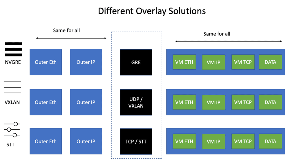
Now that SDN separates the data and control plane, the operator uses the centralized controller to choose the correct forwarding information per-flow basis. This allows better load balancing and traffic separation on the data plane. In addition, there is no need to enforce traffic separation based on VLANs, as the controller would have a set of policies and rules that would only allow traffic from one “VLAN” to be forwarded to other devices within that same “VLAN.”

The advent of VXLAN

With the advent of VXLAN, which allows up to 16 million logical entities, the benefits of SDN should not be purely associated with overcoming VLAN scaling issues. VXLAN already does an excellent job with this. It does make sense to deploy a centralized control plane in smaller independent islands; in my view, it should be at the edge of the network for security and policy enforcement roles. Using Openflow on one or more remote devices is easy to implement and scale.

It also decreases the impact of controller failure. If a controller fails and its sole job is implementing packet filters when a new user connects to the network, the only affecting element is that the new user cannot connect. If the controller is responsible for core changes, you may have interesting results with a failure. New users not being able to connect is bad, but losing your entire fabric is not as bad.

Spanning tree VXLAN
Diagram: Loop prevention. Source is Cisco
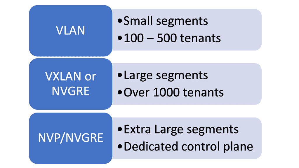
A traditional networking device runs all the control and data plane functions. The control plane, usually implemented in the central CPU or the supervisor module, downloads the forwarding instructions into the data plane structures. Every vendor needs communications protocols to bind the two planes together to download forward instructions. 
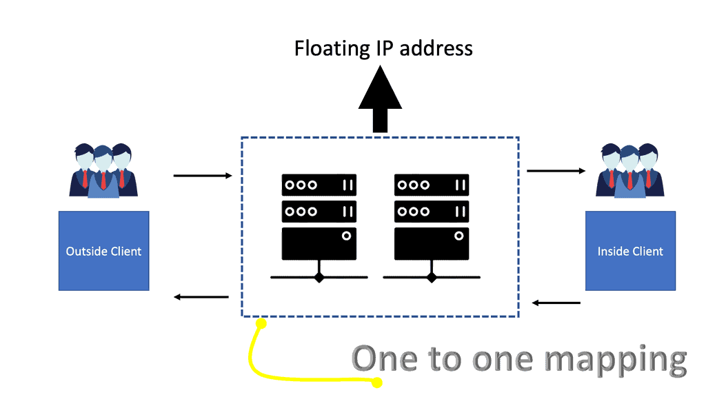
Therefore, all distributed architects need a protocol between control and data plane elements. The protocol binding this communication path for traditional vendor devices is not open-source, and every vendor uses its proprietary protocol (Cisco uses IPC—InterProcess Communication ).

Openflow tries to define a standard protocol between the control plane and the associated data plane. When you think of Openflow, you should relate it to the communication protocol between the traditional supervisors and the line cards. OpenFlow is just a low-level tool.

OpenFlow is a control plane ( controller ) to data plane ( OpenFlow enabled device ) protocol that allows the control plane to modify forwarding entries in the data plane. It enables SDN to separate the data and control planes.

identify the benefits of openflow

Proactive versus reactive flow setup

OpenFlow operations have two types of flow setups: Proactive and Reactive.

With Proactive, the controller can populate the flow tables ahead of time, similar to a typical routing. However, the packet-in event never occurs by pre-defining your flows and actions ahead of time in the switch’s flow tables. The result is all packets are forwarded at line rate. With Reactive, the network devices react to traffic, consult the OpenFlow controller, and create a rule in the flow table based on the instruction. The problem with this approach is that there can be many CPU hits.

OpenFlow protocol

The following table outlines the critical points for each type of flow setup:

Proactive flow setup

Reactive flow setup

Works well when the controller is emulating BGP or OSPF.

 Used when no one can predict when and where a new MAC address will appear.

The controller must first discover the entire topology.

 Punts unknown packets to the controller. Many CPU hits.

Discover endpoints ( MAC addresses, IP addresses, and IP subnets )

Compute forwarding paths on demand. Not off the box computation.

Compute off the box optimal forwarding.

 Install flow entries based on actual traffic.

Download flow entries to the data plane switches.

Has many scalability concerns such as packet punting rate.

No data plane controller involvement with the exceptions of ARP and MAC learning. Line-rate performance.

 Not a recommended setup.

Hop-by-hop versus path-based forwarding

The following table illustrates the key points for the two types of forwarding methods used by OpenFlow: hop-by-hop forwarding and path-based forwarding:

Hop-by-hop Forwarding

 Path-based Forwarding

Similar to traditional IP Forwarding.

Similar to MPLS.

Installs identical flows on each switch on the data path.

Map flows to paths on ingress switches and assigns user traffic to paths at the edge node

Scalability concerns relating to flow updates after a change in topology.

Compute paths across the network and installs end-to-end path-forwarding entries.

Significant overhead in large-scale networks.

Works better than hop-by-hop forwarding in large-scale networks.

FIB update challenges. Convergence time.

Core switches don’t have to support the same granular functionality as edge switches.

Obviously, with any controller, the controller is a lucrative target for attack. Anyone who knows you are using a controller-based network will try to attack the controller and its control plane. The attacker may attempt to intercept the controller-to-switch communication and replace it with its commands, essentially attacking the control plane with whatever means they like.

An attacker may also try to insert a malformed packet or some other type of unknown packet into the controller ( fuzzing attack ), exploiting bugs in the controller and causing the controller to crash. 

Fuzzing attacks can be carried out with application scanning software such as Burp Suite. It attempts to manipulate data in a particular way, breaking the application.

The best way to tighten security is to encrypt switch-to-controller communications with SSL and self-signed certificates to authenticate the switch and controller. It would also be best to minimize interaction with the data plane, except for ARP and MAC learning.

To prevent denial-of-service attacks on the controller, you can use Control Plane Policing ( CoPP ) on Ingress to avoid overloading the switch and the controller. Currently, NEC is the only vendor implementing CoPP.

sdn separates the data and control plane

The Hybrid deployment model is helpful from a security perspective. For example, you can group specific ports or VLANs to OpenFlow and other ports or VLANs to traditional forwarding, then use traditional forwarding to communicate with the OpenFlow controller.

Software-defined networking or traditional routing protocols?

The move to a Software-Defined Networking architecture has clear advantages. It’s agile and can react quickly to business needs, such as new product development. For businesses to succeed, they must have software that continues evolving.

Otherwise, your customers and staff may lose interest in your product and service. The following table displays the advantages and disadvantages of the existing routing protocol control architecture.

+Reliable and well known.

-Non-standard Forwarding models. Destination-only and not load-aware metrics**

+Proven with 20 plus years field experience.

 -Loosely coupled.

+Deterministic and predictable.

-Lacks end-to-end transactional consistency and visibility.

+Self-Healing. Traffic can reroute around a failed node or link.

-Limited Topology discovery and extraction. Basic neighbor and topology tables.

+Autonomous.

-Lacks the ability to change existing control plane protocol behavior.

+Scalable.

-Lacks the ability to introduce new control plane protocols.

+Plenty of learning and reading materials.

** Basic EIGRP IETF originally proposed an Energy-Aware Control Plane, but the IETF later removed this.

Software-Defined Networking: Use Cases

Edge Security policy enforcement at the network edge.

Authenticate users or VMs and deploy per-user ACL before connecting a user to the network.

Custom routing and online TE.

The ability to route on a variety of business metrics aka routing for dollars. Allowing you to override the default routing behavior.

Custom traffic processing.

For analytics and encryption.

Programmable SPAN ports

 Use Openflow entries to mirror selected traffic to the SPAN port.

DoS traffic blackholing & distributed DoS prevention.

Block DoS traffic as close to the source as possible with more selective traffic targeting than the original RTBH approach**. The traffic blocking is implemented in OpenFlow switches. Higher performance with significantly lower costs.

Traffic redirection and service insertion.

Redirect a subset of traffic to network appliances and install redirection flow entries wherever needed.

Network Monitoring.

 The controller is the authoritative source of information on network topology and Forwarding paths.

Scale-Out Load Balancing.

Punt new flows to the Openflow controller and install per-session entries throughout the network.

IPS Scale-Out.

OpenFlow is used to distribute the load to multiple IDS appliances.

**Remote-Triggered Black Hole: RTBH refers to installing a host route to a bogus IP address ( RTBH address ) pointing to NULL interfaces on all routers. BGP is used to advertise the host routes to other BGP peers of the attacked hosts, with the next hop pointing to the RTBH address, and it is mainly automated in ISP environments.

SDN deployment models

Guidelines:

  1. Start with small deployments away from the mission-critical production path, i.e., the Core. Ideally, start with device or service provisioning systems.
  2. Start at the Edge and slowly integrate with the Core. Minimize the risk and blast radius. Start with packet filters at the Edge and tasks that can be easily automated ( VLANs ).
  3. Integrate new technology with the existing network.
  4. Gradually increase scale and gain trust. Experience is key.
  5. Have the controller in a protected out-of-band network with SSL connectivity to the switches.

There are 4 different models for OpenFlow deployment, and the following sections list the key points of each model.

Native OpenFlow 

  • They are commonly used for Greenfield deployments.
  • The controller performs all the intelligent functions.
  • The forwarding plane switches have little intelligence and solely perform packet forwarding.
  • The white box switches need IP connectivity to the controller for the OpenFlow control sessions. If you are forced to use an in-band network for this communication path using an isolated VLAN with STP, you should use an out-of-band network.
  • Fast convergence techniques such as BFD may be challenging to use with a central controller.
  • Many people believe that this approach does not work for a regular company. Companies implementing native OpenFlow, such as Google, have the time and resources to reinvent the wheel when implementing a new control-plane protocol ( OpenFlow ).

Native OpenFlow with Extensions

  • Some control plane functions are handled from the centralized controller to the forwarding plane switches. For example, the OpenFlow-enabled switches could load balancing across multiple links without the controller’s previous decision. You could also run STP, LACP, or ARP locally on the switch without interaction with the controller. This approach is helpful if you lose connectivity to the controller. If the low-level switches perform certain controller functions, packet forwarding will continue in the event of failure.
  • The local switches should support the specific OpenFlow extensions that let them perform functions on the controller’s behalf.

Hybrid ( Ships in the night )

  • This approach is used where OpenFlow runs in parallel with the production network.
  • The same network box is controlled by existing on-box and off-box control planes ( OpenFlow).
  • Suitable for pilot deployment models as switches still run traditional control plane protocols.
  • The Openflow controller manages only specific VLANs or ports on the network.
  • The big challenge is determining and investigating the conflict-free sharing of forwarding plane resources across multiple control planes.

Integrated OpenFlow

  • OpenFlow classifiers and forwarding entries are integrated with the existing control plane. For example, Juniper’s OpenFlow model follows this mode of operation where OpenFlow static routes can be redistributed into the other routing protocols.
  • No need for a new control plane.
  • No need to replace all forwarding hardware
  • It is the most practical approach as long as the vendor supports it.

Closing Points on OpenFlow

OpenFlow is a communication protocol that provides access to the forwarding plane of a network switch or router over the network. It was initially developed at Stanford University and has since been embraced by the Open Networking Foundation (ONF) as a core component of SDN. OpenFlow allows network administrators to program the control plane, enabling them to direct how packets are forwarded through the network. This decoupling of the control and data planes is what empowers SDN to offer more dynamic and flexible network management.

The architecture of OpenFlow is quite straightforward yet powerful. It consists of three main components: the controller, the switch, and the protocol itself. The controller is the brains of the operation, managing network traffic by sending instructions to OpenFlow-enabled switches. These switches, in turn, execute the instructions received, altering the flow of network data accordingly. This setup allows for centralized network control, offering unprecedented levels of automation and agility.

**Advantages of OpenFlow**

OpenFlow brings several critical advantages to network management and control:

1. Flexibility and Programmability: With OpenFlow, network administrators can dynamically reconfigure the behavior of network devices, allowing for greater adaptability to changing network requirements.

2. Centralized Control: By centralizing control in a single controller, network administrators gain a holistic view of the network, simplifying management and troubleshooting processes.

3. Innovation and Experimentation: OpenFlow enables researchers and developers to experiment with new network protocols and applications, fostering innovation in the networking industry.

4. Scalability: OpenFlow’s centralized control architecture provides the scalability needed to manage large-scale networks efficiently.

**Implications for Network Control**

OpenFlow has significant implications for network control, paving the way for new possibilities in network management:

1. Software-Defined Networking (SDN): OpenFlow is a critical component of the broader concept of SDN, which aims to decouple network control from the underlying hardware, providing a more flexible and programmable infrastructure.

2. Network Virtualization: OpenFlow facilitates network virtualization, allowing multiple virtual networks to coexist on a single physical infrastructure.

3. Traffic Engineering: By controlling the flow of packets at a granular level, OpenFlow enables advanced traffic engineering techniques, optimizing network performance and resource utilization.

OpenFlow represents a paradigm shift in network control, offering a more flexible, scalable, and programmable approach to managing networks. By separating the control and data planes, OpenFlow empowers network administrators to have fine-grained control over network behavior, improving efficiency, innovation, and adaptability. As the networking industry continues to evolve, OpenFlow and its related technologies will undoubtedly play a crucial role in shaping the future of network management.

Summary: What is OpenFlow?

In the rapidly evolving world of networking, OpenFlow has emerged as a game-changer. This revolutionary technology has transformed the way networks are managed, offering unprecedented flexibility, control, and efficiency. In this blog post, we will delve into the depths of OpenFlow, exploring its definition, key features, and benefits.

What is OpenFlow?

OpenFlow can be best described as an open standard communications protocol that enables the separation of the control plane and the data plane in network devices. It allows centralized control over a network’s forwarding elements, making it possible to program and manage network traffic dynamically. By decoupling the intelligence of the network from the underlying hardware, OpenFlow provides a flexible and programmable infrastructure for network administrators.

Key Features of OpenFlow

a) Centralized Control: One of the core features of OpenFlow is its ability to centralize network control, allowing administrators to define and implement policies from a single point of control. This centralized control improves network visibility and simplifies management tasks.

b) Programmability: OpenFlow’s programmability empowers network administrators to define how network traffic should be handled based on their specific requirements. Through the use of flow tables and match-action rules, administrators can dynamically control the behavior of network switches and routers.

c) Software-Defined Networking (SDN) Integration: OpenFlow plays a crucial role in the broader concept of Software-Defined Networking. It provides a standardized interface for SDN controllers to communicate with network devices, enabling dynamic and automated network provisioning.

Benefits of OpenFlow

a) Enhanced Network Flexibility: With OpenFlow, network administrators can easily adapt and customize their networks to suit evolving business needs. The ability to modify network behavior on the fly allows for efficient resource allocation and improved network performance.

b) Simplified Network Management: By centralizing network control, OpenFlow simplifies the management of complex network architectures. Policies and configurations can be applied uniformly across the network, reducing administrative overhead and minimizing the chances of configuration errors.

c) Innovation and Experimentation: OpenFlow fosters innovation by providing a platform for the development and deployment of new network protocols and applications. Researchers and developers can experiment with novel networking concepts, paving the way for future advancements in the field.

Conclusion

OpenFlow has ushered in a new era of network management, offering unparalleled flexibility and control. Its ability to separate the control plane from the data plane, coupled with centralized control and programmability, has opened up endless possibilities in network architecture design. As organizations strive for more agile and efficient networks, embracing OpenFlow and its associated technologies will undoubtedly be a wise choice.

What is VXLAN

What is VXLAN

What is VXLAN

In the rapidly evolving networking world, virtualization has become critical for businesses seeking to optimize their IT infrastructure. One key technology that has emerged is VXLAN (Virtual Extensible LAN), which enables the creation of virtual networks independent of physical network infrastructure. In this blog post, we will delve into the concept of VXLAN, its benefits, and its role in network virtualization.

VXLAN is an encapsulation protocol designed to extend Layer 2 (Ethernet) networks over Layer 3 (IP) networks. It provides a scalable and flexible solution for creating virtualized networks, enabling seamless communication between virtual machines (VMs) and physical servers across different data centers or geographic regions.

VXLAN is a technology that creates virtual networks within an existing physical network. A Layer 2 overlay network runs on top of the current Layer 2 network. VXLAN utilizes UDP as the transport protocol, providing a secure, efficient, and reliable way to create a virtual network.

VXLAN encapsulates the original Layer 2 Ethernet frames within UDP packets, using a 24-bit VXLAN Network Identifier (VNI) to distinguish between different virtual networks. The encapsulated packets are then transmitted over the underlying IP network, enabling the creation of virtualized Layer 2 networks across Layer 3 boundaries.

Scalability: VXLAN solves the limitations of traditional VLANs by providing a much larger network identifier space, accommodating up to 16 million virtual networks. This scalability allows for the efficient isolation and segmentation of network traffic in highly virtualized environments.

VXLAN enables the decoupling of virtual and physical networks, providing the flexibility to move virtual machines across different physical hosts or even data centers without the need for reconfiguration. This flexibility greatly simplifies workload mobility and enhances overall network agility.

Multitenancy: With VXLAN, multiple tenants can securely share the same physical infrastructure while maintaining isolation between their virtual networks. This is achieved by assigning unique VNIs to each tenant, ensuring their traffic remains separate and secure.

Underlay Network: VXLAN relies on an IP underlay network, which must provide sufficient bandwidth, low latency, and optimal routing. Careful planning and design of the underlay network are crucial to ensure optimal VXLAN performance.

Network Virtualization Gateway: To enable communication between VXLAN-based virtual networks and traditional VLAN-based networks, a network virtualization gateway, such as a VXLAN Gateway or an overlay-to-underlay gateway, is required. These gateways bridge the gap between virtual and physical networks, facilitating seamless connectivity.

Highlights: What is VXLAN

Understanding VXLAN Basics

It is essential to grasp VXLAN’s fundamental concepts to comprehend it. VXLAN enables the creation of virtualized Layer 2 networks over an existing Layer 3 infrastructure. It uses encapsulation techniques to extend Layer 2 segments over long distances, enabling flexible deployment of virtual machines across physical hosts and data centers.

VXLAN Encapsulation: One of the key components of VXLAN is encapsulation. When a virtual machine sends data across the network, VXLAN encapsulates the original Ethernet frame within a new UDP/IP packet. This encapsulated packet is then transmitted over the underlying Layer 3 network, allowing for seamless communication between virtual machines regardless of their physical location.

VXLAN Tunneling: VXLAN employs tunneling to transport the encapsulated packets between VXLAN-enabled devices. These devices, known as VXLAN Tunnel Endpoints (VTEPs), establish tunnels to carry VXLAN traffic. By leveraging tunneling protocols like Generic Routing Encapsulation (GRE) or Virtual Extensible LAN (VXLAN-GPE), VTEPs ensure the delivery of encapsulated packets across the network.

**Benefits of VXLAN**

VXLAN brings numerous benefits to modern network architectures. It enables network virtualization and multi-tenancy, allowing for the efficient and secure isolation of network segments. VXLAN also provides scalability, as it can support a significantly higher number of virtual networks than traditional VLAN-based networks. Additionally, VXLAN facilitates workload mobility and disaster recovery, making it an ideal choice for cloud environments.

**Implementing VXLAN**

VXLAN Implementation Considerations: While VXLAN offers immense advantages, there are a few considerations to consider when implementing it. VXLAN requires network devices that support the technology, including VTEPs and VXLAN-aware switches. It is also crucial to properly configure and manage the VXLAN overlay network to ensure optimal performance and security.

Data centers evolution

In recent years, data centers have seen a significant evolution. This evolution has brought popular technologies such as virtualization, cloud computing (private, public, and hybrid), and software-defined networking (SDN). Mobile-first and cloud-native data centers must scale, be agile, secure, consolidate, and integrate with compute/storage orchestrators. As well as visibility, automation, ease of management, operability, troubleshooting, and advanced analytics, today’s data center solutions are expected to include many other features.

A more service-centric approach is replacing device-by-device management. Most requests for proposals (RFPs) specify open application programming interfaces (APIs) and standards-based protocols to prevent vendor lock-in. A Cisco Virtual Extensible LAN (VXLAN)-based fabric using Nexus switches2 and NX-OS controllers form Cisco Virtual Extensible LAN (VXLAN).

what is spine and leaf architecture
Diagram: What is spine and leaf architecture. 2-Tier Spine Leaf Design

Issues with STP

When a switch receives redundant paths, the spanning tree protocol must designate one of those paths as blocked to prevent loops. While this mechanism is necessary, it can lead to suboptimal network performance. Blocked ports limit bandwidth utilization, which can be particularly problematic in environments with heavy data traffic.

One significant concern with the spanning tree protocol is its slow convergence time. When a network topology changes, the protocol takes time to recompute the spanning tree and reestablish connectivity. During this convergence period, network downtime can occur, disrupting critical operations and causing frustration for users.

stp port states

What is VXLAN?

The Internet Engineering Task Force (IETF) developed VXLAN, or Virtual eXtensible Local-Area Network, as a network virtualization technology standard. Multi-tenant networks allow multiple organizations to share a physical network without accessing each other’s traffic.

The VXLAN can be compared to individual apartment apartments: each apartment is a separate, private dwelling within a shared physical structure, just as each VXLAN is a discrete, private network segment within a shared physical infrastructure.

With VXLANs, physical networks can be segmented into 16 million logical networks. To encapsulate Layer 2 Ethernet frames, User Datagram Protocol (UDP) packets with a VXLAN header are used. Combining VXLAN with Ethernet virtual private networks (EVPNs), which transport Ethernet traffic over WAN protocols, allows Layer 2 networks to be extended across Layer 3 IP or MPLS networks.

**Benefits of VXLAN:**

– Scalability: VXLAN allows creating up to 16 million logical networks, providing the scalability required for large-scale virtualized environments.

– Network Segmentation: By leveraging VXLAN, organizations can segment their networks into virtual segments, enhancing security and isolating traffic between applications or user groups.

– Flexibility and Mobility: VXLAN enables the movement of VMs across physical servers and data centers without the need to reconfigure network settings. This flexibility is crucial for workload mobility in dynamic environments.

– Interoperability: VXLAN is an industry-standard protocol supported by various networking vendors, ensuring compatibility across different network devices and platforms.

**Use Cases for VXLAN**

– Data Center Interconnect (DCI): VXLAN allows organizations to interconnect multiple data centers, enabling seamless workload migration, disaster recovery, and workload balancing across different locations.

– Multi-Tenant Environments: VXLAN enables service providers to offer virtualized network services to multiple tenants securely and isolatedly. This is particularly useful in cloud computing environments.

– Network Virtualization: VXLAN plays a crucial role in network virtualization, allowing organizations to create virtual networks independent of the underlying physical infrastructure. This enables greater flexibility and agility in managing network resources.

**VXLAN vs. GRE**

VXLAN, an overlay network technology, is designed to address the limitations of traditional VLANs. It enables the creation of virtual networks over an existing Layer 3 infrastructure, allowing for more flexible and scalable network deployments. VXLAN operates by encapsulating Layer 2 Ethernet frames within UDP packets, extending Layer 2 domains across Layer 3 boundaries.

GRE, on the other hand, is a simple IP packet encapsulation protocol. It provides a mechanism for encapsulating arbitrary protocols over an IP network and is widely used for creating point-to-point tunnels. GRE encapsulates the payload packets within IP packets, making it a versatile option for connecting remote networks securely.

GRE without IPsec

Point-to-point GRE networks serve as a foundational element in modern networking. They allow for encapsulation and efficient transmission of various protocols over an IP network. Point-to-point GRE networks enable seamless communication and data transfer by establishing a direct virtual link between two endpoints.

Understanding mGRE

mGRE serves as the foundation for building DMVPN networks. It allows multiple sites to communicate with each other over a shared public network infrastructure while maintaining security and scalability. By utilizing a single mGRE tunnel interface on a central hub router, multiple spoke routers can dynamically establish and tear down tunnels, enabling seamless communication across the network.

The utilization of mGRE within DMVPN offers several key advantages. First, it simplifies network configuration by eliminating the need for point-to-point tunnels between each spoke router. Second, mGRE provides scalability, allowing for the dynamic addition or removal of spoke routers without impacting the overall network infrastructure. Third, mGRE enhances network resiliency by supporting multiple paths and providing load-balancing mechanisms.

Key VXLAN advantages

Because VXLANs are encapsulated inside UDP packets, they can run on any network that can send UDP packets. No matter how physically or geographically far a VTEP is from the decapsulating VTEP, it must forward UDP datagrams. 

VXLAN and EVPN enable operators to create virtual networks from physical ports on any Layer 3 network switch supporting the standard. Connecting a port on switch A to two ports on switch B and another port on switch C creates a virtual network that appears to all connected devices as one physical network. Devices in this virtual network cannot see VXLANs or the underlying network fabric.

**Problems that VXLAN solves**

In the same way, as server virtualization has increased agility and flexibility, decoupling virtual networks from physical infrastructure has done the same. Therefore, network operators can scale their infrastructure rapidly and economically to meet growing demand while securely sharing a single physical network. For privacy and security reasons, networks are segmented to prevent one tenant from seeing or accessing the traffic of another.

In a similar way to traditional virtual LANs (VLANs), VXLANs enable operators to overcome the scaling limitations associated with VLANs.

  • Up to 16 million VXLANs can be created in an administrative domain, compared to 4094 traditional VLANs. Cloud and service providers can segment networks using VXLANs to support many tenants.
  • By using a VXLAN, you can create network segments between different data centers. In traditional VLAN networks, broadcast domains are created by segmenting traffic by VLAN tags, but once a packet containing VLAN tags reaches a router, the VLAN information is removed. There is no limit to the distance VLANs can travel within a Layer 2 network. Layer 3 boundaries, such as virtual machine migration, are generally avoided in certain use cases. Segmenting networks based on VXLAN encapsulates packets as UDP packets, while segmenting networks based on VXLAN encapsulates packets as IP packets. A virtual overlay network can extend as far as the physical Layer 3 routed network can reach when all switches and routers in the path support VXLAN without the applications running on the overlay network having to cross any Layer 3 boundaries. Servers connected to the network are still part of the Layer 2 network, even though UDP packets may have transited one or more routers.
  • Using Layer 2 segmentation on top of an underlying Layer 3 network allows one to segment a Layer 2 network over an underlying Layer 3 network and support many network segments. By providing Layer 2 segmentation on top of an underlying Layer 3 network, Layer 2 networks can remain small even if they are distant. Smaller Layer 2 networks can prevent MAC table overflows on switches.

Primary VXLAN applications

A service provider or cloud provider deploys VXLAN for apparent reasons: they have many tenants or customers, and they must separate the traffic of one customer from another due to legal, privacy, and ethical considerations.

Users, departments, or other groups of network-segmented devices may be tenants in enterprise environments for security reasons. Isolating IoT network traffic from production network applications is a good security practice for Internet of Things (IoT) devices such as data center environmental sensors.

VXLAN has been widely adopted and is now used in many large enterprise networks for virtualization and cloud computing. It provides:

  • A secure and efficient way to create virtual networks.
  • Allowing for the creation of multi-tenant segmentation.
  • Efficient routing.
  • Hardware-agnostic capabilities.

With its widespread adoption, VXLAN has become an essential technology for network virtualization.

Example: VXLAN Flood and Learn

Understanding VXLAN Flood and Learn

VXLAN flood and learn handles unknown unicast, multicast, and broadcast traffic in VXLAN networks. It allows the network to learn and forward traffic to the appropriate destination without relying on traditional flooding techniques. By leveraging multicast, VXLAN flood and learn improves efficiency and reduces the network’s reliance on flooding every unknown packet.

Proper multicast group management is essential to implementing VXLAN flood and learning with multicast. VXLAN uses multicast groups to distribute unknown traffic efficiently within the network. 

VXLAN flood and learn with multicast offers several benefits for data center networks. Firstly, it reduces the flooding of unknown traffic, which helps minimize network congestion and improves overall performance. Additionally, it allows for better scalability by avoiding the need to flood every unknown packet to all VTEPs (VXLAN Tunnel Endpoint). This results in more efficient network utilization and reduced processing overhead.

Related: Before you proceed, you may find the following posts helpful for pre-information:

  1. Data Center Topologies
  2. Segment Routing
  3. What is OpenFlow
  4. Overlay Virtual Networks
  5. Layer 3 Data Center

What is VXLAN

Traditional layer two networks have issues because of the following reasons:

  • Spanning tree: Restricts links.
  • Limited amount of VLANs: Restricts scalability;
  • Large MAC address tables: Restricts scalability and mobility

Spanning-tree avoids loops by blocking redundant links. By blocking connections, we create a loop-free topology and pay for links we can’t use. Although we could switch to a layer three network, some technologies require layer two networking.

VLAN IDs are 12 bits long, so we can create 4094 VLANs (0 and 4095 are reserved). Data centers may need help with only 4094 available VLANs. Let’s say we have a service provider with 500 customers. There are 4094 available VLANs, so each customer can only have eight.

STP Path distribution

The Role of Server Virtualization

Server virtualization has exponentially increased the number of addresses in our switches’ MAC addresses. Before server virtualization, there was only one MAC address per switch port. With server virtualization, we can run many virtual machines (VMs) or containers on a single physical server. Virtual NICs and virtual MAC addresses are assigned to each virtual machine. One switch port must learn many MAC addresses.

A data center could connect 24 or 48 physical servers to a top-of-rack (ToR) switch. Since there may be many racks in a data center, each switch must store the MAC addresses of all VMs that communicate. Networks without server virtualization require much larger MAC address tables.

Guide: VXLAN

In the following lab, I created a Layer 2 overlay with VXLAN over a Layer 3 core. A bridge domain VNI of 6001 must match both sides of the overlay tunnel. What Is a VNI? The VLAN ID field in an Ethernet frame has only 12 bits, so VLAN cannot meet isolation requirements on data center networks. The emergence of VNI specifically solves this problem.

Note: The VNI

A VNI is a user identifier similar to a VLAN ID. A VNI identifies a tenant. VMs with different VNIs cannot communicate at Layer 2. During VXLAN packet encapsulation, a 24-bit VNI is added to a VXLAN packet, enabling VXLAN to isolate many tenants.

In the screenshot below, you will notice that I can ping from desktop 0 to desktop one even though the IP addresses are not in the routing table of the core devices, simulating a Layer 2 overlay. Consider VXLAN to be the overlay and the routing Layer 3 core to be the underlay.

VXLAN overlay
Diagram: VXLAN Overlay

In the following screenshot, notice that the VNI has been changed. The VNI needs to be changed in two places in the configuration, as illustrated below. Once changed, the Peers are down; however, the NVE  interface remains up. The VXLAN layer two overlay is not operational.

Diagram: Changing the VNI

How does VXLAN work?

VXLAN uses tunneling to encapsulate Layer 2 Ethernet frames within IP packets. Each VXLAN network is identified by a unique 24-bit segment ID, the VXLAN Network Identifier (VNI). The source VM encapsulates the original Ethernet frame with a VXLAN header, including the VNI. The encapsulated packet is then sent over the physical IP network to the destination VM and decapsulated to retrieve the original Ethernet frame.

Analysis:

Notice below that it is running a ping from desktop 0 to desktop 1. The IP addresses assigned to this host are 10.0.0.1 and 10.0.0.2. First, notice that the ping is booming. When I do a packet capture on the links Gi1 connected to Leaf A, we see the encapsulation of the ICMP echo request and reply.

Everything is encapsulated into UDP port 1024. In my configurations of Leaf A and Leaf B, I explicitly set the VXLAN port to 1024.

VXLAN unicast mode

XLAN and Network Virtualization.

VXLAN and network virtualization

VXLAN is a form of network virtualization. Network virtualization cuts a single physical network into many virtual networks, often called network overlays. Virtualizing a resource allows it to be shared by multiple users. Virtualization provides the illusion that each user is on his or her resources.

In the case of virtual networks, each user is under the misconception that there are no other users of the network. To preserve the illusion, virtual networks are separated from one another. Packets cannot leak from one virtual network to another.

Network Virtualization
Diagram: Network Virtualization. Source Parallels

VXLAN Loop Detection and Prevention

So, before we dive into the benefits of VXLAN, let us address the basics of loop detection and prevention, which is a significant driver for using network overlays such as VLXAN. The challenge is that data frames can exist indefinitely when loops occur, disrupting network stability and degrading performance.

In addition, loops introduce broadcast radiation, increasing CPU and network bandwidth utilization, which degrades user application access experience. Finally, in multi-site networks, a loop can span multiple data centers, causing disruptions that are difficult to pinpoint. Overlay networking can solve much of this.

VXLAN vs VLAN

However, first-generation Layer-2 Ethernet networks could not natively detect or mitigate looped topologies, while modern Layer-2 overlays implicitly build loop-free topologies. Therefore, overlays do not need loop detection and mitigation as long as no first-gen Layer-2 network is attached. Essentially, there is no need for a VXLAN spanning tree.

So, one of the differences between VXLAN vs VLAN is that the VLAN has a 12-bit VID while VXLAN has a 24-bit VID network identifier, allowing you to create up to 16 million segments. VXLAN has tremendous scale and stable loop-free networking and is a foundation technology in the ACI Cisco.

Spanning tree VXLAN
Diagram: Loop prevention. Source is Cisco

VXLAN and Data Center Interconnect

VXLAN has revolutionized data center interconnect by providing a scalable, flexible, and efficient solution for extending Layer 2 networks. Its ability to enable network segmentation, multi-tenancy support, and seamless mobility makes it a valuable technology for modern businesses.

However, careful planning, consideration of network infrastructure, and security measures are essential for successful implementation. By harnessing the power of VXLAN, organizations can achieve a more agile, scalable, and interconnected data center environment.

VXLAN vs VLAN: The VXLAN Benefits Drive Adoption

Introduced by Cisco and VMware and now heavily used in open networking, VXLAN stands for Virtual eXtensible Local Area Network. It is perhaps the most popular overlay technology for IP-based SDN data centers and is used extensively with ACI networks.

VXLAN was explicitly designed for Layer 2 over Layer 3 tunneling. Its early competition from NVGRE and STT is fading away, and VXLAN is becoming the industry standard. VLXAN brings many advantages, especially in loop prevention, as there is no need for a VXLAN spanning tree.

VXLAN Benefits
VXLAN Benefits: Scale and loop-free networks.

Today, overlays such as VXLAN almost eliminate the dependency on loop prevention protocols. However, even though virtualized overlay networks such as VXLAN are loop-free, having a failsafe loop detection and mitigation method is still desirable because loops can be introduced by topologies connected to the overlay network.

Loop prevention traditionally started with Spanning Tree Protocols (STP) to counteract the loop problem in first-gen Layer-2 Ethernet networks. Over time, other approaches evolved by moving networks from “looped topologies” to “loop-free topologies.

While LAG and MLAG were used, other approaches for building loop-free topologies arose using ECMP at the MAC or IP layers. For example, FabricPath or TRILL is a MAC layer ECMP approach that emerged in the last decade. More recently, network virtualization overlays that build loop-free topologies on top of IP layer ECMP became state-of-the-art.

What is VXLAN
What is VXLAN and the components involved?

VXLAN vs VLAN: Why Introduce VXLAN?

  1. STP issues and scalability constraints: STP is undesirable on a large scale and lacks a proper load-balancing mechanism. A solution was needed to leverage the ECMP capabilities of an IP network while offering extended VLANs across an IP core, i.e., virtual segments across the network core. There is no VXLAN spanning tree.
  2. Multi-tenancy: Layer 2 networks are capped at 4000 VLANs, restricting multi-tenancy design—a big difference in the VXLAN vs VLAN debates.
  3. ToR table scalability: Every ToR switch may need to support several virtual servers, and each virtual server requires several NICs and MAC addresses. This pushes the limits on the ToR switch’s table sizes. In addition, after the ToR tables become full, Layer 2 traffic will be treated as unknown unicast traffic, which will be flooded across the network, causing instability to a previously stable core.
STP Blocking.
Diagram: STP Blocking. Source Cisco Press free chapter.

VXLAN use cases

Use Case 

VXLAN Details

Use Case 1

Multi-tenant IaaS Clouds where you need a large number of segments

Use Case 2

Link Virtual to Physical Servers. This is done via software or hardware VXLAN to VLAN gateway

Use Case 3

HA Clusters across failure domains/availability zones

Use Case 4

VXLAN works well over fabrics that have equidistant endpoints

Use Case 5

VXLAN-encapsulated VLAN traffic across availability zones must be rate-limited to prevent broadcast storm propagation across multiple availability zones

What is VXLAN? The operations

When discussing VXLAN vs VLAN, VXLAN employs a MAC over IP/UDP overlay scheme and extends the traditional VLAN boundary of 4000 VLANs. The 12-bit VLAN identifier in traditional VLANs capped scalability within the SDN data center and proved cumbersome if you wanted a VLAN per application segment model. VXLAN scales the 12-bit to a 24-bit identifier and allows for 16 million logical endpoints, with each endpoint potentially offering another 4,000 VLANs.

While tunneling does provide Layer 2 adjacency between these logical endpoints and allows VMs to move across boundaries, the main driver for its insertion was to overcome the challenge of having only 4000 VLAN.

Typically, an application segment has multiple segments; between each segment, you will have firewalling and load-balancing services, and each segment requires a different VLAN. The Layer 2 VLAN segment transfers non-routable heartbeats or state information that can’t cross an L3 boundary. You will soon reach the 4000k VLAN limit if you are a cloud provider.

vxlan vs vlan
Multiple segments are required per application stack.

The control plane

The control plane is very similar to the spanning tree control plane. If a switch receives a packet destined for an unknown address, the switch will forward the packet to an IP address that floods the packet to all the other switches.

This IP address is, in turn, mapped to a multicast group across the network. VXLAN doesn’t explicitly have a control plane and requires an IP multicast running in the core for forwarding traffic and host discovery.

**Best practices for enabling IP Multicast in the core**

IP Multicast

In the Core

  1. Bidirectional PIM or PIM Sparse Mode
  1. Redundant Rendezvous Points (RP)
  1. Shared trees (reduce the amount of IP multicast state)
  1. Always check the IP multicast table sizes on core and ToR switches
  1. Single IP multicast address for multiple VXLAN segments is OK

The requirement for IP multicast in the core made VXLAN undesirable from an operation point of view. For example, creating the tunnel endpoints is simple, but introducing a protocol like IP multicast to a core just for the tunnel control plane was considered undesirable. As a result, some of the more recent versions of VXLAN support IP unicast.

VXLAN uses a MAC over IP/UDP solution to eliminate the need for a spanning tree. There is no VXLAN spanning tree. This enables the core to be IP and not run a spanning tree. Many people ask why VXLAN uses UDP. The reason is that the UDP port numbers cause VXLAN to inherit Layer 3 ECMP features. The entropy that enables load balancing across multiple paths is embedded into the UDP source port of the overlay header.

2nd Lab Guide: Multicast VLXAN

In this lab guide, we will look at a VXLAN multicast mode. The multicat mode requires both unicast and multicast connectivity between sites. Similar to the previous one, this configuration guide uses OSPF to provide unicast connectivity, and now we have an additional bidirectional Protocol Independent Multicast (PIM) to provide multicast connectivity.

This does not mean that you don’t have a multicast-enabled core. It would be best if you still had multicast enabled on the core. 

So we are not tunneling multicast over an IPv4 core without having multicast enabled on the core. I have multicast on all Layer 3 interfaces, and the mroute table is populated on all Layer 3 routers. With the command: Show ip mroute, we are tunneling the multicast traffic, and with the command: Show nve vni, we have multicast group 239.0.0.10 and a state of UP.

Multicast VXLAN
Diagram: Multicast VXLAN

VXLAN benefits and stability

The underlying control plan network impacts the stability of VXLAN and the applications running within it. For example, if the underlying IP network cannot converge quickly enough, VLXAN packets may be dropped, and an application cache timeout may be triggered.

The rate of change in the underlying network significantly impacts the stability of the tunnels, yet the rate and change of the tunnels do not affect the underlying control plane. This is similar to how the strength of an MPLS / VPN overlay is affected by the core’s IGP.

VXLAN Points

VXLAN benefits

VXLAN drawbacks

Point 1

Runs over IP Transport

 No control plane

Point 2

Offers a large number of logical endpoints 

Needs IP Multicast***

Point 3

Reduced flooding scope

No IGMP snooping ( yet )

Point 4

Eliminates STP

No Pvlan support

Point 5

Easily integrated over existing Core

Requires Jumbo frames in the core ( 50 bytes)

Point 6

Minimal host-to-network integration

No built-in security features **

Point 7

Not a DCI solution ( no arp reduction, first-hop gateway localization, no inbound traffic steering i.e, LISP )

** VXLAN has no built-in security features. Anyone who gains access to the core network can insert traffic into segments. The VXLAN transport network must be secure, as no existing firewall or intrusion prevention system (IPS) equipment can be seen in the VXLAN traffic.

*** Recent versions have Unicast VXLAN. Nexus 1000V release 4.2(1)SV2(2.1)

Updated: VXLAN enhancements

MAC distribution mode is an enhancement to VXLAN that prevents unknown unicast flooding and eliminates data plane MAC address learning. Traditionally, this was done by flooding to locate an unknown end host, but it has now been replaced with a control plane solution.
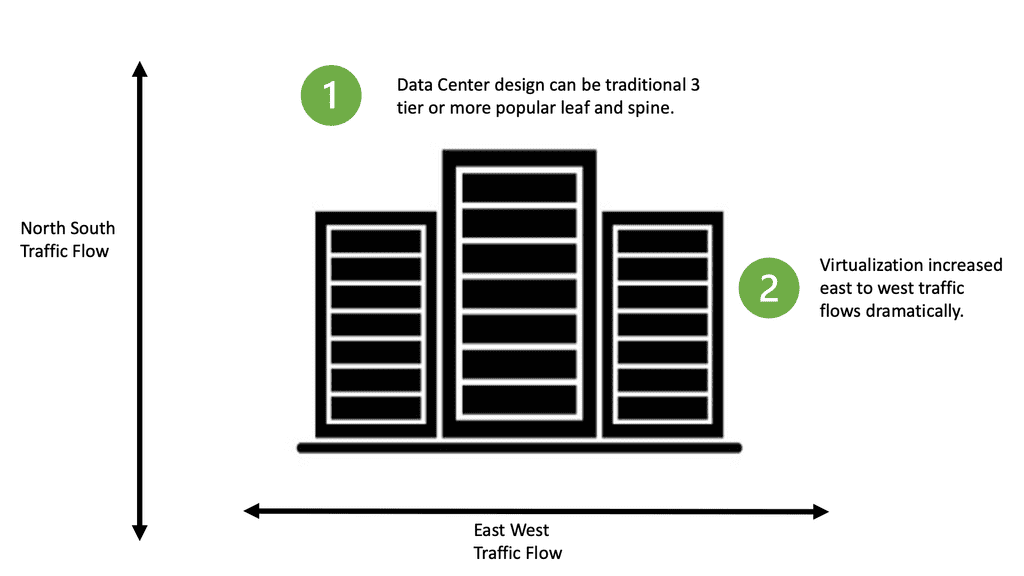
During VM startup, the VSM ( control plane ) collects the list of MAC addresses and distributes the MAC-to-VTEP mappings to all VEMs participating in a VXLAN segment. This technique makes VXLAN more optimal by unicasting more intelligently, similar to Nicira and VMware NVP.

ARP termination works by giving the VSM controller all the ARP and MAC information. This enables the VSM to proxy and respond locally to ARP requests without sending a broadcast. Because 90% of broadcast traffic is ARP requests ( ARP reply is unicast ), this significantly reduces broadcast traffic on the network.

Closing Points on VXLAN

VXLAN is a network virtualization technology that encapsulates Ethernet frames within UDP packets, allowing the creation of a virtual network overlay. This overlay extends beyond traditional VLANs, providing more address space and enabling communication across different physical networks. With a 24-bit segment ID, VXLAN supports up to 16 million unique network segments, compared to the 4096 segments possible with VLANs.

At its core, VXLAN uses tunneling to encapsulate Layer 2 frames within Layer 3 packets. This process involves two key components: the VXLAN Tunnel Endpoint (VTEP) and the VXLAN header. VTEPs are responsible for encapsulating and decapsulating the Ethernet frames. They also handle the communication between different network segments, ensuring seamless data transmission across the network.

The adoption of VXLAN brings several advantages to network management:

1. **Scalability**: VXLAN’s ability to support millions of network segments allows for unprecedented scalability, making it ideal for large-scale data centers.

2. **Flexibility**: By decoupling the network overlay from the physical infrastructure, VXLAN enables flexible network designs that can adapt to changing business needs.

3. **Improved Resource Utilization**: VXLAN optimizes the use of network resources, enhancing performance and reducing congestion by spreading traffic across multiple paths.

VXLAN is particularly beneficial in scenarios where network scalability and flexibility are paramount. Common use cases include:

– **Data Center Interconnect**: Connecting multiple data centers over a single, unified network fabric.

– **Multi-Tenant Environments**: Providing isolated network segments for different tenants in cloud environments.

– **Disaster Recovery**: Facilitating seamless failover and recovery by extending network segments across geographically dispersed locations.

Summary: What is VXLAN

VXLAN, short for Virtual Extensible LAN, is a network virtualization technology that has recently gained significant popularity. In this blog post, we will examine VXLAN’s definition, workings, and benefits. So, let’s dive into the world of VXLAN!

Understanding VXLAN Basics

VXLAN is an encapsulation protocol that enables the creation of virtual networks over existing Layer 3 infrastructures. It extends Layer 2 segments over Layer 3 networks, allowing for greater flexibility and scalability. By encapsulating Layer 2 frames within Layer 3 packets, VXLAN enables efficient communication between virtual machines (VMs) across physical hosts or data centers.

VXLAN Operation and Encapsulation

To understand how VXLAN works, we must look at its operation and encapsulation process. When a VM sends a Layer 2 frame, it is encapsulated into a VXLAN packet by adding a VXLAN header. This header includes information such as the VXLAN network identifier (VNI), which helps identify the virtual network to which the packet belongs. The VXLAN packet is then transported over the underlying Layer 3 network to the destination physical host, encapsulated, and delivered to the appropriate VM.

Benefits and Use Cases of VXLAN

VXLAN offers several benefits that make it an attractive choice for network virtualization. Firstly, it enables the creation of large-scale virtual networks, allowing for seamless VM mobility and workload placement flexibility. VXLAN also helps overcome the limitations of traditional VLANs by providing a much larger address space, accommodating the ever-growing number of virtual machines in modern data centers. Additionally, VXLAN facilitates network virtualization across geographically dispersed data centers, making it ideal for multi-site deployments and disaster recovery scenarios.

VXLAN vs. Other Network Virtualization Technologies

While VXLAN is widely used, it is essential to understand its key differences and advantages compared to other network virtualization technologies. For instance, VXLAN offers better scalability and flexibility than traditional VLANs. It also provides better isolation and segmentation of virtual networks, making it an ideal choice for multi-tenant environments. Additionally, VXLAN is agnostic to the physical network infrastructure, allowing it to be easily deployed in existing networks without requiring significant changes.

Conclusion:

In conclusion, VXLAN is a powerful network virtualization technology that has revolutionized how virtual networks are created and managed. Its ability to extend Layer 2 networks over Layer 3 infrastructures, scalability, flexibility, and ease of deployment make VXLAN a go-to solution for modern data centers. Whether for workload mobility, multi-site implementations, or overcoming VLAN limitations, VXLAN offers a robust and efficient solution. Embracing VXLAN can unlock new possibilities in network virtualization, enabling organizations to build agile, scalable, and resilient virtual networks.
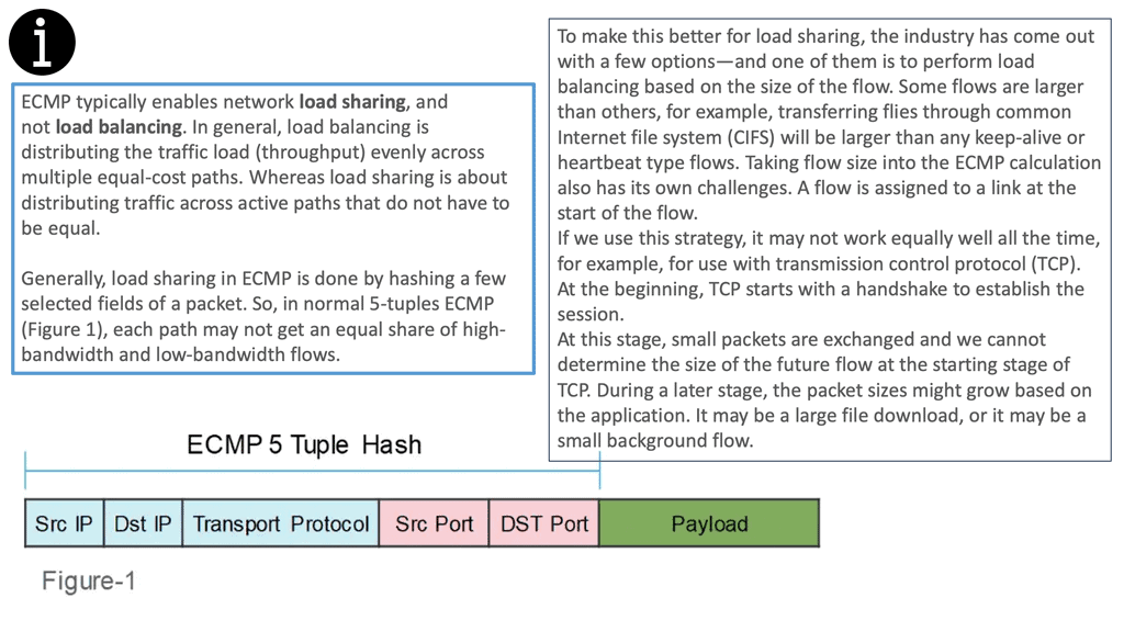
multipath tcp

Data Center Topologies

Data Center Topology

In the world of technology, data centers play a crucial role in storing, managing, and processing vast amounts of digital information. However, behind the scenes, a complex infrastructure known as data center topology enables seamless data flow and optimal performance. In this blog post, we will delve into the intricacies of data center topology, its different types, and how it impacts the efficiency and reliability of data centers.

Data center topology refers to a data center's physical and logical layout. It encompasses the arrangement and interconnection of various components like servers, storage devices, networking equipment, and power sources. A well-designed topology ensures high availability, scalability, and fault tolerance while minimizing latency and downtime. As technology advances, so does the landscape of data center topologies. Here are a few emerging trends worth exploring:

Leaf-Spine Architecture: This modern approach replaces the traditional three-tier architecture with a leaf-spine model. It offers high bandwidth, low latency, and improved scalability, making it ideal for cloud-based applications and data-intensive workloads.

Software-Defined Networking (SDN): SDN introduces a new level of flexibility and programmability to data center topologies. By separating the control plane from the data plane, it enables centralized management, automated provisioning, and dynamic traffic optimization.

The chosen data center topology has a significant impact on the overall performance and reliability of an organization's IT infrastructure. A well-designed topology can optimize data flow, minimize latency, and prevent bottlenecks. By considering factors such as fault tolerance, scalability, and network traffic patterns, organizations can tailor their topology to meet their specific needs.

Highlights: Data Center Topology

A data center consists of the following core infrastructure components:

  • Network infrastructure: Connects physical and virtual servers, data center services, storage, and external connections to end users.
  • Storage Infrastructure: Modern data centers use storage infrastructure to power their operations. Storage systems hold this valuable commodity.
  • A data center’s computing infrastructure is its applications. The computing infrastructure comprises servers that provide processors, memory, local storage, and application network connectivity. In the last 65 years, computing infrastructure has undergone three major waves:
    • In the first wave of replacements of proprietary mainframes, x86-based servers were installed on-premises and managed by internal IT teams.
    • In the second wave, application infrastructure was widely virtualized, improving resource utilization and workload mobility across physical infrastructure pools.
    • The third wave finds us in the present, where we see the move to the cloud, hybrid cloud, and cloud-native (that is, applications born in the cloud).

Common Types of Data Center Topologies:

a) Bus Topology: In this traditional topology, all devices are connected linearly to a common backbone, resembling a bus. While it is simple and cost-effective, a single point of failure can disrupt the entire network.

b) Star Topology: Each device is connected directly to a central switch or hub in a star topology. This design offers centralized control and easy troubleshooting, but it can be expensive due to the requirement of additional cabling.

c) Mesh Topology: A mesh topology provides redundant connections between devices, forming a network where every device is connected to every other device. This design ensures high fault tolerance and scalability but can be complex and costly.

d) Hybrid Topology: As the name suggests, a hybrid topology combines elements of different topologies to meet specific requirements. It offers flexibility and allows organizations to optimize their infrastructure based on their unique needs.

**Considerations in Data Center Topology Design**

a) Redundancy: Redundancy is essential to ensure continuous operation even during component failures. By implementing redundant paths, power sources, and network links, data centers can minimize the risk of downtime and data loss.

b) Scalability: As the data center’s requirements grow, the topology should be able to accommodate additional devices and increased data traffic. Scalability can be achieved through modular designs, virtualization, and flexible network architectures.

c) Performance and Latency: The distance between devices, the quality of network connections, and the efficiency of routing protocols significantly impact data center performance and latency. Optimal topology design considers these factors to minimize delays and ensure smooth data transmission.

Google Cloud NCC

### What is Google Network Connectivity Center?

Google NCC is a centralized platform that provides a holistic view of your network infrastructure. It integrates with Google Cloud, enabling businesses to manage their global networks with ease. The platform is built to support hybrid and multi-cloud environments, ensuring that your data center operations are streamlined and efficient.

### Key Features and Benefits

#### Unified Network Management

One of the standout features of Google NCC is its ability to consolidate various network management tasks into a single interface. This means less time spent juggling multiple tools and more time focusing on core business activities.

#### Enhanced Security

Security is a critical concern for any organization. Google NCC incorporates robust security measures, including end-to-end encryption and advanced threat detection, to safeguard your network against potential risks.

#### Scalability and Flexibility

As your business grows, so does your need for a scalable network solution. Google NCC offers unparalleled scalability, allowing you to expand your network infrastructure effortlessly. Its flexibility ensures that it can adapt to the ever-changing demands of your business.
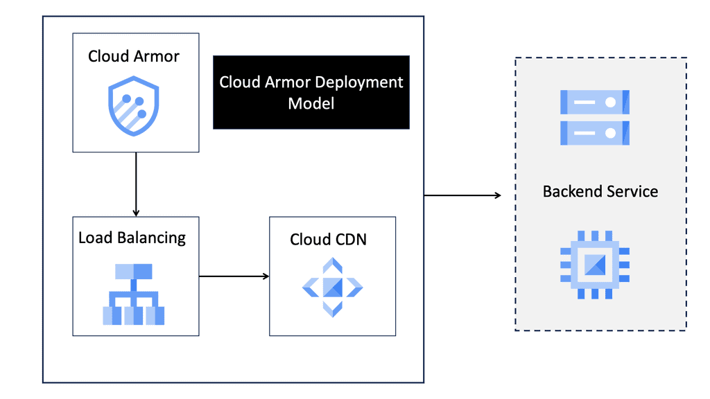
### Integrating with Data Centers

Google NCC is designed to seamlessly integrate with your existing data centers. This integration ensures that you can manage your on-premises and cloud-based resources from a single platform. The result is a more cohesive and efficient network management experience.

### Real-World Applications

#### Enterprise Connectivity

For large enterprises, managing a sprawling network can be a daunting task. Google NCC simplifies this by providing a unified platform that can handle complex network topologies. This makes it easier to connect multiple branch offices, remote workers, and cloud services.

#### Optimized Performance

Google NCC leverages advanced algorithms to optimize network performance. This ensures that your applications run smoothly and that data is transmitted efficiently. Whether you’re running a global e-commerce site or a high-demand application, NCC has you covered.

Impact of Data Center Topology:

Efficient data center topology directly influences the entire infrastructure’s reliability, availability, and performance. A well-designed topology reduces single points of failure, enables load balancing, enhances fault tolerance, and optimizes data flow. It directly impacts the user experience, especially for cloud-based services, where data centers simultaneously cater to many users.

Knowledge Check: Cisco ACI Building Blocks

Before Cisco ACI 4.1, the Cisco ACI fabric supported only a two-tier (leaf-and-spine switch) topology in which leaf switches are connected to spine switches without interconnecting them. Starting with Cisco ACI 4.1, the Cisco ACI fabric allows multitier (three-tier) fabrics and two tiers of leaf switches, allowing vertical expansion. As a result, a traditional three-tier aggregation access architecture can be migrated, which is still required for many enterprise networks.

In some situations, building a full-mesh two-tier fabric is not ideal due to the high cost of fiber cables and the limitations of cable distances. A spine-leaf topology is more efficient in these cases, and Cisco ACI continues to automate and improve visibility.

ACI fabric Details
Diagram: Cisco ACI fabric Details

Choosing a topology

Data centers are the backbone of many businesses, providing the necessary infrastructure to store and manage data and access applications and services. As such, it is essential to understand the different types of available data center topologies.

When choosing a topology for a data center, the organization’s specific needs and requirements must be considered. Each topology offers its advantages and disadvantages, so it is crucial to understand the pros and cons of each before making a decision.

A data center topology refers to the physical layout and interconnection of network devices within a data center. It determines how servers, switches, routers, and other networking equipment are connected, ensuring efficient and reliable data transmission. Topologies are based on scalability, fault tolerance, performance, and cost.

Scalability of the topology

Additionally, it is essential to consider the topology’s scalability, as a data center may need to accommodate future growth. By understanding the different topologies and their respective strengths and weaknesses, organizations can make the best decision for their data centers. For example, in a spine-and-leaf architecture, traffic traveling from one server to another always crosses the same number of devices (unless both servers are located on the same leaf). Payloads need only hop to a spine switch and another leaf switch to reach their destination, thus reducing latency.

what is spine and leaf architecture

Data Center Topology Types

Centralized Model

Smaller data centers (less than 5,000 square feet) may benefit from the centralized model. It is shown that there are separate local area networks (LANs) and storage area networks (SANs), with home-run cables going to each server cabinet and zone. Each server is effectively connected back to the core switches in the main distribution area.

As a result, port switches can be utilized more efficiently, and components can be managed and added more quickly. The centralized topology works well for smaller data centers but does not scale up well, making expansion difficult. Many cable runs in larger data centers cause cable pathways and cabinets congestion and increase costs.

Zoned or top-of-rack topologies may be used in large data centers for LAN traffic, but centralized architectures may be used for SAN traffic. In particular, port utilization is essential when SAN switch ports are expensive.

Zoned Topology

Distributed switching resources make up a zoned topology. Typically, chassis-based switches support multiple server cabinets and can be distributed among end-of-row (EoR) and middle-of-row (MoR) locations. It is highly scalable, repeatable, and predictable and is recommended by the ANS/TIA-942 Data Center Standards.

A zoned architecture provides the highest switch and port utilization level while minimizing cabling costs. Switching at the end of a row can be advantageous in certain situations. Two servers’ local area network (LAN) ports can be connected to the same end-of-row switch for low-latency port-to-port switching.

Having to run cable back to the end-of-row switch is a potential disadvantage of end-of-row switching. It is possible for this cabling to exceed that required for a top-of-rack system if every server is connected to redundant switches.

Top-of-rack (ToR)

Switches are typically placed at the top of a server rack to provide top-of-rack (ToR) switching, as shown below. Using this topology is a good option for dense one-rack-unit (1RU) server environments. For redundancy, both switches are connected to all servers in the rack. There are uplinks to the next layer of switching from the top-of-rack switches.

It simplifies cable management and minimizes cable containment requirements when cables are managed at the top of the rack. Using this approach, servers within the rack can quickly switch from port to port, and the uplink oversubscription is predictable.

In top-of-rack designs, cabling is more efficiently utilized. In exchange, there is usually an increase in the cost of switches and a high cost for under-utilization of ports. There is also the possibility of overheating local area network (LAN) switch gear in server racks when top-of-rack switching is required.

Data Center Architecture Types

Mesh architecture

Mesh networks, known as “network fabrics” or leaf-spine, consist of meshed connections between leaf-and-spine switches.  They are well suited for supporting universal “cloud services” because the mesh of network links enables any-to-any connectivity with predictable capacity and lower latency. The mesh network has multiple switching resources scattered throughout the data center, making it inherently redundant. Compared to huge, centralized switching platforms, these distributed network designs can be more cost-effective to deploy and scale.

Multi-Tier

Multi-tier architectures are commonly used in enterprise data centers. In this design, mainframes, blade servers, 1RU servers, and mainframes run the web, application, and database server tiers.

Mesh point of delivery

Mesh point of delivery (PoD) architectures have leaf switches interconnected within PoDs, and spine switches aggregated in a central main distribution area (MDA). This architecture also enables multiple PoDs to connect efficiently to a super-spine tier. Three-tier topologies that support east-west data flows will be able to support new cloud applications with low latency. Mesh PoD networks can provide a pool of low-latency computing and storage for these applications that can be added without disrupting the existing environment.

Super Spine architectecutre

Hyperscale organizations that deploy large-scale data center infrastructures or campus-style data centers often deploy super spine architecture. This type of architecture handles data passing east to west across data halls.

Cloud Data Centers

Understanding Network Tiers

Network tiers refer to the different levels of service quality and performance that a network can offer. They allow businesses to prioritize and allocate resources based on their specific needs. In the case of Google Cloud, there are two primary network tiers: Premium Tier and Standard Tier.

The Premium Tier in Google Cloud offers businesses a top-of-the-line network experience. It leverages Google’s private global network, which is interconnected with major internet service providers (ISPs) worldwide.

This interconnectivity ensures low latency, high bandwidth, and enhanced reliability for mission-critical workloads. By utilizing the Premium Tier, businesses can deliver an exceptional user experience, reduce downtime, and ensure optimal performance for latency-sensitive applications.

While the Premium Tier provides unparalleled performance, the Standard Tier offers a more cost-effective alternative for businesses with less latency-sensitive workloads. The Standard Tier leverages public internet transit, providing reliable and secure connectivity at a lower price point.

This tier is ideal for applications that can tolerate slightly higher latency, such as batch processing, non-real-time analytics, or backup and recovery tasks. By utilizing the Standard Tier, businesses can achieve significant cost savings without sacrificing overall network reliability.

Understanding VPC Networking

VPC networking forms the foundation of your cloud infrastructure, allowing you to create and manage virtual networks with ease. In Google Cloud, VPC networks provide isolation and connectivity for your resources, ensuring secure communication and data transfer.

Google Cloud’s VPC networking offers a plethora of powerful features. These include custom IP ranges, subnets, firewall rules, routes, and VPN connectivity. Custom IP ranges enable you to define IP addresses for your virtual network, while subnets allow you to divide your network into smaller segments for better organization and control.

Understanding VPC Peering

VPC Peering is a networking arrangement that enables communication between two virtual private clouds (VPCs) in the same or different projects within Google Cloud. It establishes a direct, private connection between VPC networks, allowing them to communicate as if they were part of the same network.

VPC Peering offers numerous benefits to organizations leveraging Google Cloud. First, it enables seamless and secure communication between VPC networks, eliminating the need for complex VPN setups or publicly exposing resources. Second, it allows for low-latency data transfer, ensuring optimal performance for applications and services. Third, it simplifies network management, enabling centralized administration of connected VPCs.

Related: For pre-information, you may find the following post helpful

  1. ACI Cisco
  2. Virtual Switch
  3. Ansible Architecture
  4. Overlay Virtual Networks

Data Center Topology

The Role of Networks

A network lives to serve the connectivity requirements of applications and applications. We build networks by designing and implementing data centers. A common trend is that the data center topology is much bigger than a decade ago, with application requirements considerably different from the traditional client-server applications and with deployment speeds in seconds instead of days. This changes how networks and your chosen data center topology are designed and deployed.

The traditional network design was scaled to support more devices by deploying larger switches (and routers). This is the scale-in model of scaling. However, these large switches are expensive and primarily designed to support only a two-way redundancy.

Today, data center topologies are built to scale out. They must satisfy the three main characteristics of increasing server-to-server traffic, scale ( scale on-demand ), and resilience. The following diagram shows a ToR design we discussed at the start of the blog.

Top of Rack (ToR)
Diagram: Data center network topology. Top of Rack (ToR).

The Role of The ToR

Top of rack (ToR) is a term used to describe the architecture of a data center. It is a server architecture in which servers, switches, and other equipment are mounted on the same rack. This allows for the most efficient use of space since the equipment is all within arm’s reach.

ToR is also the most efficient way to manage power and cooling since the equipment is all in the same area. Since all the equipment is close together, ToR also allows faster access times. This architecture can also be utilized in other areas, such as telecommunications, security, and surveillance.

ToR is a great way to maximize efficiency in any data center and is becoming increasingly popular. In contrast to the ToR data center design, the following diagram shows an EoR switch design.

End of Row (EoR)
Diagram: Data center network topology. End of Row (EoR).

The Role of The EoR

The term end-of-row (EoR) design is derived from a dedicated networking rack or cabinet placed at either end of a row of servers to provide network connectivity to the servers within that row. In EoR network design, each server in the rack has a direct connection with the end-of-row aggregation switch, eliminating the need to connect servers directly with the in-rack switch.

Racks are usually arranged to form a row; a cabinet or rack is positioned at the end of this row. This rack has a row aggregation switch, which provides network connectivity to servers mounted in individual racks. This switch, a modular chassis-based platform, sometimes supports hundreds of server connections. However, a large amount of cabling is required to support this architecture.

Data center topology types
Diagram: ToR and EoR. Source. FS Community.

A ToR configuration requires one switch per rack, resulting in higher power consumption and operational costs. Moreover, unused ports are often more significant in this scenario than with an EoR arrangement.

On the other hand, ToR’s cabling requirements are much lower than those of EoR, and faults are primarily isolated to a particular rack, thus improving the data center’s fault tolerance.

If fault tolerance is the ultimate goal, ToR is the better choice, but EoR configuration is better if an organization wants to save on operational costs. The following table lists the differences between a ToR and an EoR data center design.

data center network topology
Diagram: Data center network topology. The differences. Source FS Community

Data Center Topology Types:

Fabric extenders – FEX

Cisco has introduced the concept of Fabric Extenders, which are not Ethernet switches but remote line cards of a virtualized modular chassis ( parent switch ). This allows scalable topologies previously impossible with traditional Ethernet switches in the access layer.

You should relate an FEX device like a remote line card attached to a parent switch. All the configuration is done on the parent switch, yet physically, the fabric extender could be in a different location. The mapping between the parent switch and the FEX ( fabric extender ) is done via a special VN-Link.

The following diagram shows an example of a FEX in a standard data center network topology. More specifically, we are looking at the Nexus 2000 FEX Series. Cisco Nexus 2000 Series Fabric Extenders (FEX) are based on the standard IEEE 802.1BR. They deliver fabric extensibility with a single point of management.

Cisco FEX
Diagram: Cisco FEX design. Source Cisco.

Different types of Fex solution

FEXs come with various connectivity solutions, including 100 Megabit Ethernet, 1 Gigabit Ethernet, 10 Gigabit Ethernet ( copper and fiber ), and 40 Gigabit Ethernet. They can be synchronized with the following parent switch models: Nexus 5000, Nexus 6000, Nexus 7000, Nexus 9000, and Cisco UCS Fabric Interconnect.

In addition, because of FEX’s simplicity, they have very low latency ( as low as 500 nanoseconds ) compared to traditional Ethernet switches.

Data Center design
Diagram: Data center fabric extenders.

Some network switches can be connected to others and operate as a single unit. These configurations are called “stacks” and are helpful for quickly increasing the capacity of a network. A stack is a network solution composed of two or more stackable switches. Switches that are part of a stack behave as one single device.

Traditional switches like the 3750s still stand in the data center network topology access layer and can be used with stacking technology, combining two physical switches into one logical switch.

This stacking technology allows you to build a highly resilient switching system, one switch at a time. If you are looking at a standard access layer switch like the 3750s, consider the next-generation Catalyst 3850 series.

The 3850 supports BYOD/mobility and offers various performance and security enhancements compared to previous models. However, stacking has a drawback: You can only stack several switches. So, if you want more throughout, you should aim for a different design type.

Data Center Design: Layer 2 and Layer 3 Solutions

Traditional views of data center design

Depending on the data center network topology deployed, packet forwarding at the access layer can be either Layer 2 or Layer 3. A Layer 3 approach would involve additional management and configuring IP addresses on hosts in a hierarchical fashion that matches the switch’s assigned IP address.

An alternative approach is to use Layer 2, which has less overhead as Layer 2 MAC addresses do not need specific configuration. However, it has drawbacks with scalability and poor performance.

Generally, access switches focus on communicating servers in the same IP subnet, allowing any type of traffic – unicast, multicast, or broadcast. You can, however, have filtering devices such as a Virtual Security Gateway ( VSG ) to permit traffic between servers, but that is generally reserved for inter-POD ( Platform Optimized Design ) traffic.

Leaf and Spine With Layer 3

We use a leaf and spine data center design with Layer 3 everywhere and overlay networking. This modern, robust architecture provides a high-performance, highly available network. With this architecture, data center networks are composed of leaf switches that connect to one or more spine switches.

The leaf switches are connected to end devices such as servers, storage devices, and other networking equipment. The spine switches, meanwhile, act as the network’s backbone, connecting the multiple leaf switches.

The leaf and spine architecture provides several advantages over traditional data center networks. It allows for greater scalability, as additional leaf switches can be easily added to the network. It also offers better fault tolerance, as the network can operate even if one of the spine switches fails.

Furthermore, it enables faster traffic flows, as the spine switches to route traffic between the leaf switches faster than a traditional flat network.

Data Center Traffic Flow

Datacenter topologies can have North-South or East-to-West traffic. North-south ( up / down ) corresponds to traffic between the servers and the external world ( outside the data center ). East-to-west corresponds to internal server communication, i.e., traffic does not leave the data center.

Therefore, determining the type of traffic upfront is essential as it influences the type of topology used in the data center.

data center traffic flow
Diagram: Data center traffic flow.

For example, you may have a pair of ISCSI switches, and all traffic is internal between the servers. In this case, you would need high-bandwidth inter-switch links. Usually, an ether channel supports all the cross-server talk; the only north-to-south traffic would be management traffic.

In another part of the data center, you may have data server farm switches with only HSRP heartbeat traffic across the inter-switch links and large bundled uplinks for a high volume of north-to-south traffic. Depending on the type of application, which can be either outward-facing or internal, computation will influence the type of traffic that will be dominant. 

Virtual Machine and Containers.

This drive was from virtualization, virtual machines, and container technologies regarding east-west traffic. Many are moving to a leaf and spine data center design if they have a lot of east-to-west traffic and want better performance.

Network Virtualization and VXLAN

Network virtualization and the ability of a physical server to host many VMs and move those VMs are also used extensively in data centers, either for workload distribution or business continuity. This will also affect the design you have at the access layer.

For example, in a Layer 3 fabric, migrating a VM across that boundary changes its IP address, resulting in a reset of the TCP sessions because, unlike SCTP, TCP does not support dynamic address configuration. In a Layer 2 fabric, migrating a VM incurs ARP overhead and requires forwarding on millions of flat MAC addresses, which leads to MAC scalability and poor performance problems.

VXLAN: stability over Layer 3 core

Network virtualization plays a vital role in the data center. Technologies like VXLAN attempt to move the control plane from the core to the edge and stabilize the core so that it only has a handful of addresses for each ToR switch. The following diagram shows the ACI networks with VXLAN as the overlay that operates over a spine leaf architecture.

Layer 2 and 3 traffic is mapped to VXLAN VNIs that run over a Layer 3 core. The Bridge Domain is for layer 2, and the VRF is for layer 3 traffic. Now, we have the separation of layer 2 and 3 traffic based on the VNI in the VXLAN header.  

One of the first notable differences between VXLAN and VLAN was scale. VLAN has a 12-bit identifier called VID, while VXLAN has a 24-bit identifier called a VID network identifier. This means that with VLAN, you can create only 4094 networks over ethernet, while with VXLAN, you can create up to 16 million.

Whether you can build layer 2 or layer 3 in the access and use VXLAN or some other overlay to stabilize the core, it would help if you modularized the data center. The first step is to build each POD or rack as a complete unit. Each POD will be able to perform all its functions within that POD.

  • A key point: A POD data center design

POD is a design methodology that aims to simplify, speed deployment, optimize resource utilization, and drive the interoperability of three or more data center components: server, storage, and networks.

  • A POD example: Data center modularity

For example, one POD might be a specific human resources system. The second is modularity based on the type of resources offered. For example, a storage pod or bare metal compute may be housed in separate pods.

These two modularization types allow designers to easily control inter-POD traffic with predefined policies. Operators can also upgrade PODs and a specific type of service at once without affecting other PODs.

However, this type of segmentation does not address the data center’s scale requirements. Even when we have adequately modularized the data center into specific portions, the MAC table sizes on each switch still increase exponentially as the data center grows.

Current and Future Design Factors

New technologies with scalable control planes must be introduced for a cloud-enabled data center, and these new control planes should offer the following:

Option

Data Center Feature

Data center feature 1

The ability to scale MAC addresses

Data center feature 2

First-Hop Redundancy Protocol ( FHRP ) multipathing and Anycast HSRP

Data center feature 3

Equal-Cost multipathing

Data center feature 4

MAC learning optimizations

Several design factors need to be considered when designing a data center. First, what is the growth rate for servers, switch ports, and data center customers? This prevents part of the network topology from becoming a bottleneck or linking congested.

**Application bandwidth demand?**

This demand is usually translated into oversubscription. In data center networking, oversubscription refers to how much bandwidth switches are offered to downstream devices at each layer.

Oversubscription is expected in a data center design. Limiting oversubscription to the ToR and edge of the network offers a single place to start when performance problems occur.

A data center with no oversubscription ratio will be costly, especially with a low latency network design. So, it’s best to determine what oversubscription ratio your applications support and work best. Optimizing your switch buffers to improve performance is recommended before you decide on a 1:1 oversubscription rate.

**Ethernet 6-byte MAC addressing is flat**

Ethernet forms the basis of data center networking in tandem with IP. Since its inception 40 years ago, Ethernet frames have been transmitted over various physical media, even barbed wire. Ethernet 6-byte MAC addressing is flat; the manufacturer typically assigns the address without considering its location.

Ethernet-switched networks do not have explicit routing protocols to ensure readability about the flat addresses of the server’s NICs. Instead, flooding and address learning are used to create forwarding table entries.

**IP addressing is a hierarchy**

On the other hand, IP addressing is a hierarchy, meaning that its address is assigned by the network operator based on its location in the network. A hierarchy address space advantage is that forwarding tables can be aggregated. If summarization or other routing techniques are employed, changes in one side of the network will not necessarily affect other areas.

This makes IP-routed networks more scalable than Ethernet-switched networks. IP-routed networks also offer ECMP techniques that enable networks to use parallel links between nodes without spanning tree disabling one of those links. The ECMP method hashes packet headers before selecting a bundled link to avoid out-of-sequence packets within individual flows. 

Equal Cost Load Balancing

Equal-cost load balancing is a method for distributing network traffic among multiple paths of equal cost. It provides redundancy and increases throughput. Sending traffic over numerous paths avoids congestion on any single link. In addition, the load is equally distributed across the paths, meaning that each path carries roughly the same total traffic.

ecmp
Diagam: ECMP 5 Tuple hash. Source: Keysight

This allows for using multiple paths at a lower cost, providing an efficient way to increase throughput.

The idea behind equal-cost load balancing is to use multiple paths of equal cost to balance the load on each path. The algorithm considers the number of paths, each path’s weight, and each path’s capacity. It also considers the number of packets that must be sent and the delay allowed for each packet.

Considering these factors, it can calculate the best way to distribute the load among the paths.

Equal-cost load balancing can be implemented using various methods. One method is to use a Link Aggregation Protocol (LACP), which allows the network to use multiple links and distribute the traffic among the links in a balanced way.

ecmp
Diagam: ECMP 5 Tuple hash. Source: Keysight
  • A keynote: Data center topologies. The move to VXLAN.

Given the above considerations, a solution encompassing the benefits of L2’s plug-and-play flat addressing and IP scalability is needed. Location-Identifier Split Protocol ( LISP ) has a set of solutions that use hierarchical addresses as locators in the core and flat addresses as identifiers in the edges. However, not much is seen in its deployment these days.

Equivalent approaches such as THRILL and Cisco FabricPath create massive scalable L2 multipath networks with equidistant endpoints. Tunneling is also being used to extend down to the server and access layer to overcome the 4K limitation with traditional VLANs. What is VXLAN? Tunneling with VXLAN is now the standard design in most data center topologies with leaf-spine designs. The following video provides VXLAN guidance.

Data Center Network Topology

Leaf and spine data center topology types

This is commonly seen in a leaf and spine design. For example, in a leaf-spine fabric, We have a Layer 3 IP fabric that supports equal-cost multi-path (ECMP) routing between any two endpoints in the network. Then, on top of the Layer 3 fabric is an overlay protocol, commonly VXLAN.

A spine-leaf architecture consists of a data center network topology with two switching layers: a spine and a leaf. The leaf layer comprises access switches that aggregate traffic from endpoints such as servers and connect directly to the spine or network core.

Spine switches interconnect all leaf switches in a full-mesh topology. The leaf switches do not directly connect. The Cisco ACI is a data center topology that utilizes the leaf and spine.

The ACI network’s physical topology is a leaf and spine, while the logical topology is formed with VXLAN. From a protocol side point, VXLAN is the overlay network, and the BGP and IS-IS provide the Layer 3 routing, the underlay network that allows the overlay network to function.

As a result, the nonblocking architecture performs much better than the traditional data center design based on access, distribution, and core designs.

**Closing Points: Data Center Topologies**

A data center topology refers to the physical layout and interconnection of network devices within a data center. It determines how servers, switches, routers, and other networking equipment are connected, ensuring efficient and reliable data transmission. Topologies are based on scalability, fault tolerance, performance, and cost.

  • Hierarchical Data Center Topology:

The hierarchical or tree topology is one of the most commonly used data center topologies. This design consists of multiple core, distribution, and access layers. The core layer connects all the distribution layers, while the distribution layer connects to the access layer. This structure enables better management, scalability, and fault tolerance by segregating traffic and minimizing network congestion.

  • Mesh Data Center Topology:

Every network device is interlinked in a mesh topology, forming a fully connected network with multiple paths for data transmission. This redundancy ensures high availability and fault tolerance. However, this topology can be cost-prohibitive and complex, especially in large-scale data centers.

  • Leaf-Spine Data Center Topology:

The leaf-spine topology is gaining popularity due to its scalability and simplicity. It consists of interconnected leaf switches at the access layer and spine switches at the core layer. This design allows for non-blocking, low-latency communication between any leaf switch and spine switch, making it suitable for modern data center requirements.

  • Full-Mesh Data Center Topology:

As the name suggests, the full-mesh topology connects every network device to every other device, creating an extensive web of connections. This topology offers maximum redundancy and fault tolerance. However, it can be expensive to implement and maintain, making it more suitable for critical applications with stringent uptime requirements.

Summary: Data Center Topology

Data centers are vital in supporting and enabling our digital infrastructure in today’s interconnected world. Behind the scenes, intricate network topologies ensure seamless data flow, allowing us to access information and services easily. In this blog post, we dived into the world of data center topologies, unraveling their complexities and understanding their significance.

Understanding Data Center Topologies

Datacenter topologies refer to a data center’s physical and logical layout of networking components. These topologies determine how data flows between servers, switches, routers, and other network devices. By carefully designing the topology, data center operators can optimize performance, scalability, redundancy, and fault tolerance.

Common Data Center Topologies

There are several widely adopted data center topologies, each with its strengths and use cases. Let’s explore some of the most common ones:

Tree Topology:

Tree topology, or hierarchical topology, is widely used in data centers. It features a hierarchical structure with multiple layers of switches, forming a tree-like network. This topology offers scalability and ease of management, making it suitable for large-scale deployments.

Mesh Topology:

The mesh topology provides a high level of redundancy and fault tolerance. In this topology, every device is connected to every other device, forming a fully interconnected network. While it offers robustness, it can be complex and costly to implement.

Spine-Leaf Topology:

The spine-leaf topology, known as a Clos network, has recently gained popularity. It consists of leaf switches connecting to multiple spine switches, forming a non-blocking fabric. This design allows for efficient east-west traffic flow and simplified scalability.

Factors Influencing Topology Selection

Choosing the right data center topology depends on various factors, including:

Scalability:

A topology must accommodate a data center’s growth. Scalable topologies ensure that additional devices can be seamlessly added without causing bottlenecks or performance degradation.

Redundancy and Fault Tolerance:

Data centers require high availability to minimize downtime. Topologies that offer redundancy and fault tolerance mechanisms, such as link and device redundancy, are crucial in ensuring uninterrupted operations.

Traffic Patterns:

Understanding the traffic patterns within a data center is essential for selecting an appropriate topology. Some topologies excel in handling east-west traffic, while others are better suited for north-south traffic flow.

Conclusion

Datacenter topologies form the backbone of our digital infrastructure, providing the connectivity and reliability needed for our ever-expanding digital needs. By understanding the intricacies of these topologies, we can better appreciate the complexity involved in keeping our data flowing seamlessly. Whether it’s the hierarchical tree, the fully interconnected mesh, or the efficient spine-leaf, each topology has its place in the world of data centers.

Data Center Network Design

Data Center Network Design

Data centers are crucial in today’s digital landscape, serving as the backbone of numerous businesses and organizations. A well-designed data center network ensures optimal performance, scalability, and reliability. This blog post will explore the critical aspects of data center network design and its significance in modern IT infrastructure.

Data center network design involves the architectural planning and implementation of networking infrastructure within a data center environment. It encompasses various components such as switches, routers, cables, and protocols. A well-designed network ensures seamless communication, high availability, and efficient data flow.

The traditional three-tier network architecture is being replaced by more streamlined and flexible designs. Two popular approaches gaining traction are the spine-leaf architecture and the fabric-based architecture. The spine-leaf design offers low latency, high bandwidth, and improved scalability, making it ideal for large-scale data centers. On the other hand, fabric-based architectures provide a unified and simplified network fabric, enabling efficient management and enhanced performance.

Network virtualization, powered by technologies like SDN, is transforming data center network design. By decoupling the network control plane from the underlying hardware, SDN enables centralized network management, automation, and programmability. This results in improved agility, better resource allocation, and faster deployment of applications and services.

With the rising number of cyber threats, ensuring robust security and resilience has become paramount. Data center network design should incorporate advanced security measures such as firewalls, intrusion detection systems, and encryption protocols. Additionally, implementing redundant links, load balancing, and disaster recovery mechanisms enhances network resilience and minimizes downtime.

Highlights: Data Center Network Design

Data Center Network Design

To embark on a successful network design journey, it is essential first to understand the data center’s specific requirements. Factors such as scalability, bandwidth, latency, and reliability need to be carefully assessed. By comprehending the data center’s unique needs, network architects can lay a solid foundation for an optimized design.

Efficiency and resilience are at the core of any well-designed data center network. Building on the requirements identified in the previous section, architects must consider redundancy, load balancing, and fault tolerance principles. The design should minimize single points of failure while maximizing resource utilization and network performance.

Various network topologies and architectures can be employed in data center network design. Each option offers unique advantages and trade-offs, from traditional hierarchical designs to modern approaches like leaf-spine architectures. This section will explore different topologies, highlighting their strengths and considerations.

Virtualization and SDN have revolutionized data center network design, offering increased flexibility and agility. By abstracting network functions from physical infrastructure, virtualization allows for dynamic resource allocation and improved scalability. SDN further enhances network programmability, enabling centralized management and automation. This section will delve into the benefits and implementation considerations of these technologies.

Network, security, and computing

– A data center architecture consists of three main components: the data center network, the data center security, and the data center computing architecture. In addition to these three types of architecture, there are also data center physical architectures and data center information architectures. The following are three typical compositions.

– Network architecture for data centers: Data center networks (DCNs) are arrangements of network devices interconnecting data center resources. They are a crucial research area for Internet companies and large cloud computing firms. The design of a data center depends on its network architecture.

– It is common for routers and switches to be arranged in hierarchies of two or three levels. There are three-tier DCNs: fat tree DCNs, DCells, and others. There has always been a focus on scalability, robustness, and reliability regarding data center network architectures.

– Data center security refers to physical practices and virtual technologies for protecting data centers from threats, attacks, and unauthorized access. It can be divided into two components: physical security and software security. A firewall between a data center’s external and internal networks can protect it from attack.

Data Center Network Design Considerations

a. Understanding the Requirements

Before embarking on the design process, it’s crucial to understand the data center’s unique requirements. Factors such as power and cooling, network connectivity, scalability, and security are vital in determining the design approach. By thoroughly assessing these requirements, architects can create a blueprint that aligns with the organization’s current and future needs.

b. Optimizing Physical Layout

The physical layout of a data center significantly impacts its efficiency and performance. This section will delve into rack placement, aisle design, cable management, and airflow optimization. By adopting best practices in physical layout design, data center operators can minimize energy consumption, reduce maintenance costs, and enhance overall operational efficiency.

c. Redundancy and Resilience

Data centers demand high levels of redundancy and resilience to ensure uninterrupted operations. This section will explore the concept of redundancy in power and cooling systems, backup generators, redundant network connectivity, and failover mechanisms. Implementing robust redundancy measures helps mitigate the risk of downtime and ensures continuous availability of critical services.

4. Security and Compliance

Data centers store sensitive and valuable information, making security a top priority. This section will discuss the importance of physical security measures, access controls, surveillance systems, and fire suppression mechanisms. Additionally, we will explore compliance standards and regulations that govern data center operations, such as SOC 2, ISO 27001, and GDPR.

5. Embracing Green Initiatives

As environmental sustainability gains importance, data centers seek ways to minimize their carbon footprint. This section will focus on energy-efficient design practices, including using renewable energy sources, efficient cooling techniques, and server virtualization. Data centers can contribute to a more sustainable future by adopting green initiatives.

Data Center Network Security 

### What is Cloud Armor?

Cloud Armor is a security service offered by Google Cloud that provides protection against distributed denial-of-service (DDoS) attacks and other web-based threats. It leverages Google’s global infrastructure to offer scalable and reliable protection, ensuring that your applications and services remain available and secure even in the face of large-scale attacks.

### Key Features of Cloud Armor

Cloud Armor comes packed with several features that make it an indispensable tool for modern enterprises. Some of its key features include:

– **DDoS Protection:** Automatically detects and mitigates DDoS attacks, ensuring minimal disruption to your services.

– **Web Application Firewall (WAF):** Provides customizable rules to block malicious traffic and protect against common web vulnerabilities.

– **Edge Security Policies:** Allows you to define security policies at the edge of your network, ensuring threats are mitigated before they reach your core infrastructure.

– **Adaptive Protection:** Uses machine learning to identify and respond to evolving threats in real-time.

### Understanding Edge Security Policies

One of the standout features of Cloud Armor is its ability to implement edge security policies. These policies enable organizations to enforce security measures at the periphery of their network, providing an additional layer of defense. By stopping threats at the edge, you can prevent them from penetrating deeper into your network, thereby reducing the risk of data breaches and other security incidents.

Edge security policies can be tailored to your specific needs, allowing you to block traffic based on various criteria such as IP address, geographic location, and request patterns. This granular control helps you enforce stringent security measures while maintaining the performance and availability of your services.

### Benefits of Using Cloud Armor

Deploying Cloud Armor offers several benefits that can significantly enhance your security posture. These include:

– **Scalability:** Designed to handle traffic spikes and large-scale attacks, ensuring your services remain available even under heavy load.

– **Customization:** Flexible rules and policies allow you to tailor security measures to your unique requirements.

– **Proactive Defense:** Real-time threat detection and mitigation keep your applications protected against the latest cyber threats.

– **Cost-Effective:** By leveraging Google’s global infrastructure, you can achieve enterprise-level security without the need for significant upfront investment.

### What is Google Network Connectivity Center?

Google Network Connectivity Center is a unified platform designed to manage and monitor network connections across a variety of environments. Whether you’re dealing with on-premises data centers, cloud environments, or hybrid setups, NCC provides a centralized control point. It simplifies the complexities involved in network management, allowing IT teams to focus on optimizing performance rather than troubleshooting issues.

### Key Features of Google NCC

#### Unified Management

NCC offers a single pane of glass for managing network connections, making it easier to oversee and control your entire network infrastructure. This unified management approach reduces the need for multiple tools and interfaces, streamlining operations and increasing efficiency.

#### Flexible Connectivity Options

Google NCC supports a range of connectivity options, including VPNs, interconnects, and peering. This flexibility ensures that you can choose the best connectivity method for your specific needs, whether it’s connecting remote offices or integrating with third-party cloud services.

#### Real-Time Monitoring and Analytics

One of the standout features of NCC is its real-time monitoring and analytics capabilities. With detailed insights into network performance and traffic patterns, you can quickly identify and resolve issues, optimize resource allocation, and ensure consistent network performance.

Understanding Network Tiers

Network tiers are a concept that categorizes network traffic based on its importance and priority. By classifying traffic into different tiers, businesses can allocate resources accordingly and optimize their network usage. In the case of Google Cloud, there are two main network tiers: Premium Tier and Standard Tier.

The Premium Tier is designed to deliver exceptional performance and reliability. It leverages Google’s global network infrastructure, ensuring low latency and high throughput for critical applications. By utilizing the Premium Tier, businesses can enhance user experience, reduce latency-related issues, and improve overall network performance.

While the Premium Tier offers top-tier performance, the Standard Tier provides a cost-effective solution for non-critical workloads. It offers reliable network connectivity at a lower price point, making it an excellent choice for applications that do not require ultra-low latency or high bandwidth. By strategically utilizing the Standard Tier, businesses can optimize their network spend without compromising on reliability.

Understanding VPC Networking

VPC, or Virtual Private Cloud, is a virtual network dedicated to a specific Google Cloud project. It allows users to define and manage their network resources, including subnets, IP addresses, and firewall rules. With VPC networking, businesses can create isolated environments and control the flow of traffic within their cloud infrastructure.

Google Cloud’s VPC networking offers a range of powerful features. Firstly, it provides global connectivity, allowing businesses to connect resources across regions seamlessly. Additionally, VPC peering enables secure communication between different VPC networks, facilitating collaboration and data sharing. Moreover, VPC networking offers granular control through firewall rules, ensuring robust security for applications and services.

What is Google Cloud CDN?

Google Cloud CDN, short for Content Delivery Network, is a globally distributed network of servers designed to deliver content to users at blazing-fast speed. Cloud CDN minimizes latency and ensures a seamless user experience by caching your content in strategic locations worldwide. Whether it’s static assets, dynamic content, or even streaming media, Cloud CDN optimizes the delivery process, reducing the load on your origin servers and improving overall performance.

Cloud CDN operates by leveraging Google’s extensive network infrastructure. When a user requests content from your website or application, Cloud CDN intelligently routes the request to the nearest edge location. If the content is already cached at that edge location, it is immediately delivered to the user, eliminating the need for a round trip to the origin server. This not only reduces latency but also saves bandwidth and server resources.

Understanding VPC Network Peering

VPC network peering connects VPC networks from different projects or within the same project within Google Cloud. It enables direct communication between these networks, eliminating the need for complex VPN setups or public IP addresses. This seamless connectivity can significantly enhance collaboration, data sharing, and network management.

Enhanced Security: VPC network peering ensures that communication between peered networks remains isolated from the public internet. This adds an extra layer of security by reducing the exposure to potential cyber threats.

Improved Performance: By leveraging VPC network peering, data can be transferred at incredibly high speeds between peered networks. This enables faster resource access, reduces latency, and enhances overall application performance.

Simplified Network Architecture: VPC network peering allows for a more streamlined and simplified network architecture. Instead of relying on complex gateways or routers, communication between VPCs can be established directly, making network management and troubleshooting more straightforward.

Data Center Network Types

a. The Three-Tier Data Center Network

The three-tier DCN architecture has been a traditional approach in data center networking. It consists of three layers: the access layer, the aggregation layer, and the core layer. Each layer serves a specific purpose, from connecting end devices to aggregating traffic and providing high-speed connectivity. This hierarchical design allows for scalability and redundancy, making it a popular choice for many data centers.

b. Unleashing the Power of Fat Tree Data Center Networks

The fat tree DCN, also known as the Clos network, has gained prominence recently due to its ability to handle large-scale data center deployments. Unlike the three-tier DCN, a fat tree network provides multiple paths between devices, enabling better load balancing and higher bandwidth capacity. Fat tree networks offer low-latency communication and enhanced fault tolerance by utilizing a non-blocking switching fabric, making them ideal for mission-critical applications.

c. Exploring the Revolutionary DCell Approach

The DCell architecture takes a novel approach to data center networking and offers a unique perspective on scalability and fault tolerance. DCell networks are based on a hierarchical structure of cells, where each cell consists of a group of servers connected together. This decentralized design eliminates the need for traditional core switches and enables direct server-to-server communication. With its self-organizing capabilities, DCell networks provide excellent scalability, fault tolerance, and efficient resource utilization.

Composition of Data Center Architecture

Routing and Switching:

Routing is the backbone of a data center network, guiding data packets through the labyrinthine pathways. It involves determining the optimal path for data to travel from source to destination, considering network congestion, latency, and cost factors. Advanced routing protocols like Border Gateway Protocol (BGP) enable dynamic route selection, ensuring efficient and fault-tolerant data delivery.

Switching complements routing by facilitating efficient data transmission within a local network. At the heart of a data center, switches act as intelligent traffic controllers, directing data packets to their intended destinations. With features like VLANs (Virtual Local Area Networks) and Quality of Service (QoS), switches prioritize and prioritize traffic, optimizing network performance and ensuring seamless communication.

stp port states

Example: Spanning Tree Uplink Fast

Spanning Tree Protocol (STP) prevents loops in Ethernet networks by creating a loop-free logical topology and blocking redundant paths. While STP ensures network stability, it can also introduce delays in network convergence. Network downtime caused by STP convergence can be a primary concern for businesses. Even a few seconds of downtime can result in significant losses in critical environments. This is where Spanning Tree Uplink Fast comes into play. Uplink Fast is an enhancement to STP that provides faster convergence times, reducing network downtime and improving overall network efficiency.

How Uplink Fast Works

Uplink Fast allows a switch to detect a link failure on its designated root port and immediately activate an alternate port. This process eliminates the need for the traditional STP convergence process, resulting in faster network recovery times. Uplink Fast is instrumental when network redundancy is crucial, such as in data centers or enterprise networks.

Introducing Spanning Tree MST

Spanning Tree MST enhances the traditional STP, providing a more efficient and flexible solution. MST allows network administrators to divide the network into multiple regions, each with its own Spanning Tree instance. By doing so, MST optimizes network resources and enables load balancing across multiple paths, leading to increased performance and redundancy.
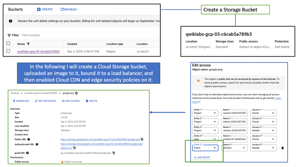
To implement Spanning Tree MST, network switches need to be properly configured. This involves defining regions, assigning VLANs to instances, and configuring parameters such as root bridges and priorities. MST configuration can be complex, but with careful planning and understanding, it offers significant benefits.

Spanning Tree MST offers several key advantages. First, it enables efficient utilization of network resources by load-balancing traffic across multiple paths. Second, it provides enhanced redundancy, ensuring that if one path fails, traffic can automatically reroute through an alternate path. Third, MST simplifies network management by allowing administrators to control traffic flow and prioritize specific VLANs within each instance.

Data Center Security Technologies

Understanding the MAC Move Policy

The MAC Move Policy is a crucial feature in Cisco NX-OS devices that governs the movement of MAC addresses within a network. By defining specific rules and criteria, administrators can control how MAC addresses are learned, aged, and moved across different interfaces and VLANs.

Configuring the MAC Move Policy

Proper configuration is essential to effectively utilizing the MAC Move Policy. This section will guide you through the step-by-step process of configuring the policy on Cisco NX-OS devices. From defining the MAC move parameters to implementing the policy on specific interfaces or VLANs, we will cover all the necessary commands and considerations to ensure a seamless configuration experience.

Understanding MAC ACLs

MAC ACLs, also known as Ethernet ACLs or Layer 2 ACLs, operate at the data link layer of the OSI model. Unlike traditional IP-based ACLs, which focus on network layer addresses, MAC ACLs allow administrators to filter traffic based on MAC addresses. This enables granular control over network access, providing an additional layer of defense against unauthorized devices.

By implementing MAC ACLs on the Nexus 9000 series, network administrators can exercise enhanced control over their network environment. MAC ACLs prevent MAC address spoofing, mitigating the risk of unauthorized devices gaining access. Furthermore, they enable the isolation of specific devices or groups of devices, ensuring that only designated entities can communicate within a given VLAN or network segment.

Understanding VLANs and ACLs

Before we embark on our journey to explore VLAN ACLs’ potential, let’s establish a solid foundation by understanding VLANs and ACLs individually. VLANs (Virtual Local Area Networks) allow us to logically segment networks, improving performance, scalability, and network management. On the other hand, ACLs (Access Control Lists) act as gatekeepers, controlling traffic flow and enforcing security policies.

VLAN ACLs serve as a crucial layer of defense in protecting our networks from unauthorized access, malicious activities, and potential breaches. By implementing VLAN ACLs, we can define granular rules that filter and restrict traffic between VLANs, ensuring that only desired communication occurs. This level of control empowers network administrators to mitigate risks, maintain data integrity, and enforce compliance.

Understanding Nexus Switch Profiles

Nexus switch profiles are a feature of Cisco’s Nexus series switches that allow administrators to define and manage a group of switches as a single entity. By creating a profile, administrators can easily configure and monitor all switches within the group, eliminating the need for repetitive manual configurations. This centralization of management simplifies network administration and saves valuable time and resources.

One of the primary advantages of using Nexus switch profiles is the ability to streamline network operations. With a profile in place, administrators can make changes or updates to configurations across multiple switches simultaneously. This significantly reduces the risk of configuration errors and ensures consistent settings throughout the network. Furthermore, the centralized management approach simplifies troubleshooting and enables faster resolution of network issues.

Data Center Technologies

Understanding Layer 3 Etherchannel

Layer 3 Etherchannel is a link aggregation technique that combines multiple physical links between switches into a single logical channel. By bundling these links together, traffic can be distributed across them, increasing overall bandwidth capacity and providing load-balancing capabilities. Unlike Layer 2 Etherchannel, Layer 3 Etherchannel operates at the network layer, allowing traffic to be routed.

To configure Layer 3 Etherchannel, several steps need to be followed. First, the physical interfaces on the switches need to be identified and grouped into the Etherchannel bundle. Then, a logical interface, the Port-Channel interface, is created and assigned an IP address. Subsequently, routing protocols or static routes can be configured on the Port-Channel interface to enable communication between different networks.

Layer 3 Etherchannel supports various load-balancing algorithms, determining how traffic is distributed across the bundled links. Standard algorithms include source IP, destination IP, and round-robin. Each algorithm has advantages and considerations depending on the network requirements and traffic patterns.

Cisco Nexus 9000 Port Channel

Implementing Port Channels on Cisco Nexus 9000 switches offers several advantages. Firstly, it provides increased link bandwidth, allowing for efficient data transfer and reducing bottlenecks. Secondly, Port Channels enhance network resilience by providing link redundancy. In a link failure, traffic seamlessly switches to the remaining active links. Lastly, Port Channels enable load balancing, distributing network traffic evenly across the aggregated links for optimal utilization.

Setting up a Port Channel on Cisco Nexus 9000 switches is straightforward. Administrators can configure Port Channels using the Link Aggregation Control Protocol (LACP) or the Port Aggregation Protocol (PAgP). Administrators can maximize the benefits of this feature by adequately configuring interfaces and assigning them to the Port Channel.

Understanding Unidirectional Link Detection (UDLD)

UDLD is a layer 2 protocol that helps identify and mitigate the presence of unidirectional links in a network. It works by exchanging periodic messages between neighboring switches to verify bidirectional connectivity. By detecting unidirectional links, UDLD helps prevent potential network issues such as black holes, spanning-tree loops, and data loss.

Cisco Nexus 9000 switches offer seamless integration and support for UDLD. To enable UDLD on a Nexus 9000 switch, administrators can utilize simple commands within the switch configuration. By configuring UDLD timers, administrators can customize the frequency of UDLD messages exchanged between switches. Additionally, UDLD can be configured to operate in either standard or aggressive mode, depending on the specific needs of the network environment.

Understanding VRRP

VRRP, an essential networking protocol, provides automatic failover and load-balancing capabilities. It allows multiple routers to work as a virtual group, presenting a single IP address. By intelligently distributing network traffic, VRRP ensures seamless connectivity even in the face of router failures.

The Nexus 9000 Series, Cisco’s flagship product line, offers a range of cutting-edge features, including VRRP. Designed to meet the demands of modern networks, these switches deliver exceptional performance, scalability, and flexibility. With the Nexus 9000 Series, network administrators can harness the power of VRRP to build a robust and highly available network infrastructure.

Example: Data Center WAN Protocol

BGP, also known as the routing protocol of the Internet, is responsible for exchanging routing and reachability information among autonomous systems (AS). It enables routers to make intelligent decisions about the most optimal paths for data transmission. Unlike interior gateway protocols, BGP focuses on routing between different networks rather than within a single network.

BGP operates on a trust-based model, where routers form peer relationships to exchange routing information. These peers establish connections and exchange routing updates, allowing them to build a complete picture of network reachability. BGP uses a sophisticated algorithm that considers multiple factors, such as path length, quality of service, and policy-based decisions, to determine the best route for traffic.

Understanding BGP AS Prepend

AS Prepend involves adding additional Autonomous System (AS) numbers to the AS path attribute of BGP advertisements. By manipulating the AS path, network operators can influence inbound traffic routing decisions by neighboring autonomous systems. This technique makes a specific path appear less desirable, diverting traffic to alternative paths.

AS Prepend holds excellent potential for optimizing network routing in various scenarios. It can achieve load balancing across multiple links, redirect traffic to less congested paths, or prefer specific transit providers. By carefully implementing AS Prepend, network administrators can improve network performance, reduce latency, and enhance overall service quality.

BGP AS Prepend

Recap: Border Gateway Protocol (BGP) is data centers’ most commonly used routing protocol. It has been used to connect Internet systems worldwide for decades and can also be used outside a data center. The BGP protocol is a standard-based open-source software package. It’s more common to find BGP peering between data centers over the WAN. However, we see BGP often used purely inside the data center.

 Understanding Leaf and Spine Networks

Leaf and spine networks, also known as Clos networks, are a modern approach to data center architecture. The design revolves around a hierarchical structure consisting of two key components: leaf switches and spine switches. Leaf switches connect directly to endpoints, while spine switches interconnect the leaf switches, forming a non-blocking fabric. This architecture eliminates bottlenecks and enables seamless scalability.

BGP (Border Gateway Protocol) is a crucial routing protocol in leaf and spine networks. It ensures efficient data forwarding between leaf switches using a set of rules known as BGP route advertisements. By default, BGP requires every router to have a full mesh of connections with all other routers in the network, which can be resource-intensive. This is where BGP route reflection comes into play.

Understanding BGP Route Reflection

BGP route reflection, at its core, is a method that allows a BGP speaker to reflect routing information to its peers, alleviating the need for full-mesh connectivity. Designating specific BGP routers as route reflectors streamlines and manages the network structure.

The utilization of BGP route reflection offers several advantages. First, it reduces the number of required BGP peering sessions, resulting in a simplified and less resource-intensive network. Second, route reflection enhances scalability by eliminating the need for full-mesh connectivity, particularly in large-scale networks. Third, it improves convergence time and reduces BGP update processing overhead, enhancing overall network performance.

**The third wave of application architectures**

Google and Amazon, two of the world’s leading web-scale pioneers, developed a modern data center. The third wave of application architectures represents these organizations’ search and cloud applications. Towards the end of the 20th century, client-server architectures and monolithic single-machine applications dominated the landscape. This third wave of applications has three primary characteristics:

Unlike client-server architectures, modern data center applications involve a lot of communication between servers. In client-server architectures, clients communicate with monolithic servers, which either handle the request entirely themselves or communicate with fewer than a handful of other servers, such as database servers. Search (or Hadoop, its more popular variant) employs many mappers and reducers instead of search. In the cloud, virtual machines can reside on different nodes but must communicate seamlessly. In some cases, VMs are deployed on servers with the least load, scaled out, or balanced loads.

A microservices architecture also increases server-to-server communication. This architecture is based on separating a single function into smaller building blocks and interacting with them. Each block can be used in several applications and enhanced, modified, and fixed independently in such an architecture. Since diagrams usually show servers next to each other, East-West traffic is often called server communication. Traffic flows north-south between local networks and external networks.

**Scale and resilience**

The sheer size of modern data centers is characterized by rows and rows of dark, humming, blinking machines. As opposed to the few hundred or so servers of the past, a modern data center contains between a few hundred and a hundred thousand servers. To address the connectivity requirements at such scales, as well as the need for increased server-to-server connectivity, network design must be rethought. Unlike older architectures, modern data center applications assume failures as a given. Failures should be limited to the smallest possible footprint. Failures must have a limited “blast radius.” By minimizing the impact of network or server failures on the end-user experience, we aim to provide a stable and reliable experience.

**Data Center Goal: Interconnect networks**

The goal of data center design and interconnection network is to transport end-user traffic from A to B without any packet drops, yet the metrics we use to achieve this goal can be very different. The data center is evolving and progressing through various topology and technology changes, resulting in multiple network designs.  The new data center control planes we see today, such as Fabric Path, LISP, THRILL, and VXLAN, are driven by a change in the end user’s requirements; the application has changed. These new technologies may address new challenges, yet the fundamental question of where to create the Layer 2/Layer three boundaries and the need for Layer 2 in the access layer remains the same. The question stays the same, yet the technologies available to address this challenge have evolved.

Example Protocol: Understanding VXLAN

VXLAN, an encapsulation protocol, enables the creation of virtualized Layer 2 networks over an existing Layer 3 infrastructure. By extending the Layer 2 domain, VXLAN allows the seamless transfer of network traffic between geographically dispersed data centers. It achieves this by encapsulating Ethernet frames within IP packets, providing flexibility and scalability to network virtualization.

Scalability and Flexibility: VXLAN addresses the limitations of traditional VLANs by allowing for a significantly more significant number of virtual networks—up to 16 million—compared to the 4,096 limit of VLANs. This scalability enables organizations to allocate virtual networks more efficiently while accommodating the growing demands of cloud-based applications and services.

Enhanced Network Segmentation and Isolation: VXLAN provides improved network segmentation by creating logical networks that are isolated from one another, even if they share the same physical infrastructure. This isolation enhances security and enables more granular control over network traffic, facilitating efficient multi-tenancy in cloud environments.

VXLAN unicast mode

Modern Data Centers

There is a vast difference between modern data centers and what they used to be just a few years ago. Physical servers have evolved into virtual networks that support applications and workloads across pools of physical infrastructure and into a multi-cloud environment. There are multiple data centers, the edge, and public and private clouds where data exists and is connected. Both on-premises and cloud-based data centers must be able to communicate. Data centers are even part of the public cloud. Cloud-hosted applications use the cloud provider’s data center resources.

Unified Fabric

Through Cisco’s fabric-based data center infrastructure, tiered silos and inefficiencies of multiple network domains are eliminated, and a unified, flat fabric is provided instead, which allows local area networks (LANs), storage area networks (SANs), and network-attached storage (NASs) to be consolidated into one high-performance, fault-tolerant network. Creating large pools of virtualized network resources that can be easily moved and rapidly reconfigured with Cisco Unified Fabric provides massive scalability and resiliency to the data center.

This approach automatically deploys virtual machines and applications, thereby reducing complexity. Thanks to deep integration between server and network architecture, secure IT services can be delivered from any device within the data center, between data centers, or beyond. In addition to Cisco Nexus switches, Cisco Unified Fabric uses Cisco NX-OS as its operating system.

The use of Open Networking

We also have the Open Networking Foundation ( ONF ), which provides open networking. Open networking describes a network that uses open standards and commodity hardware. So, consider open networking in terms of hardware and software. Unlike a vendor approach like Cisco, this gives you much more choice with what hardware and software you use to make up and design your network.

Data Center Performance Parameters

TCP Performance Parameters

TCP (Transmission Control Protocol) is the backbone of modern Internet communication, ensuring reliable data transmission across networks. However, various parameters that determine TCP’s behavior can influence its performance. 

Understanding TCP Window Size: One crucial parameter that affects TCP performance is the window size. The TCP window size refers to the amount of data sent before an acknowledgment is required. A larger window size allows more data to be transmitted without waiting for acknowledgments, thus optimizing throughput. However, substantial window sizes can result in congestion and increased retransmissions.

Congestion Control Mechanisms: Congestion control mechanisms are vital in maintaining network stability and preventing congestion collapse. TCP utilizes algorithms such as Slow Start, Congestion Avoidance, and Fast Recovery to regulate data flow based on network conditions. These mechanisms ensure fairness and efficiency, improving TCP performance and avoiding network congestion.

Timeouts and Retransmission: TCP implements a reliable data transfer mechanism using acknowledgments and timeouts. When a packet is not acknowledged within a specific timeframe, it is considered lost, and TCP initiates retransmission. The selection of appropriate timeout values is crucial to balance reliability and responsiveness. Setting shorter timeouts may lead to unnecessary retransmissions, whereas longer ones can increase latency.

 Selective Acknowledgments and SACK Options: Selective acknowledgments (SACK) enhance TCP performance and recovery from packet loss. SACK lets the receiver inform the sender about specific out-of-order packets received successfully. This enables the sender to retransmit only the necessary packets, reducing unnecessary retransmissions and improving overall efficiency.

Maximum Segment Size (MSS): The Maximum Segment Size (MSS) is another crucial TCP performance parameter defining the maximum amount of data encapsulated within a single TCP segment. Optimizing the MSS can significantly impact performance, especially when network links have different MTU (Maximum Transmission Unit) sizes.

Understanding TCP MSS

TCP MSS refers to the maximum amount of data encapsulated within a single TCP segment. It represents the size of the payload, excluding headers and other overhead. The MSS value is negotiated during the TCP handshake process and remains constant throughout the connection.

The TCP MSS value has a direct impact on network performance and efficiency. Setting an appropriate MSS value ensures optimal network resource utilization and avoids unnecessary data packet fragmentation. Properly configuring TCP MSS becomes crucial when networks have different MTU (Maximum Transmission Unit) sizes.

Fragmentation occurs when the MSS value exceeds the MTU of a network path. This fragmentation can lead to performance degradation, increased latency, and potential packet loss. By carefully managing the TCP MSS value, network administrators can prevent or minimize fragmentation issues and enhance overall network performance.

Configuring TCP MSS requires a thorough understanding of the network infrastructure and the devices involved. It involves adjusting the MSS value at various points within the network, such as routers, firewalls, and load balancers. Aligning the TCP MSS value with the MTU of the underlying network ensures efficient data transmission and avoids unnecessary fragmentation.

Advanced Topics

VXLAN Flood and Learn Mechanism

The flood-and-learn mechanism in VXLAN plays a crucial role in facilitating communication between virtual machines within the overlay network. When a virtual machine sends a broadcast or unknown unicast frame, the frame is encapsulated in a VXLAN packet and flooded throughout the network. Each VXLAN tunnel endpoint (VTEP) learns the source MAC address and VTEP association, enabling subsequent unicast traffic to be directly delivered.

Multicast is a fundamental component of VXLAN flood and learn, offering several benefits. First, using multicast VXLAN reduces bandwidth consumption compared to traditional flooding techniques. Second, multicast enables efficient replicating broadcast, multicast, and unknown unicast traffic across the overlay network. Third, it enhances network scalability by eliminating the need to maintain a multicast group per tenant.

BGP Multipath

Understanding BGP Multipath

BGP multipath is a feature that enables the installation and usage of multiple paths for a single prefix in the routing table. Traditionally, BGP selects a single best path based on factors such as AS path length, origin type, and path attributes. However, with multipath enabled, BGP can utilize multiple paths simultaneously, distributing traffic across them for load balancing and redundancy purposes.

The utilization of BGP multipath brings several advantages to network operators. First, it enhances network resilience by providing redundant paths. In the event of a link failure or congestion, traffic can be automatically rerouted through available alternate paths, ensuring continuous connectivity. Additionally, BGP multipath facilitates load balancing, enabling more efficient utilization of network resources and better traffic distribution across multiple links.

Understanding BGP Next Hop Tracking

BGP next-hop tracking monitors the reachability of the next-hop IP address associated with a particular route. It allows routers to dynamically adjust their routing tables based on changes in the network topology. Routers can make informed decisions about forwarding traffic by continuously tracking the next hop, ensuring optimal path selection.

Enhanced Network Resiliency: BGP next-hop tracking enables routers to detect and respond to network changes quickly. If a next hop becomes unreachable, routers can automatically reroute traffic to an alternative path, minimizing downtime and improving network resiliency.

Load Balancing and Traffic Engineering: Network administrators gain granular control over traffic distribution with BGP next-hop tracking. By monitoring the reachability of multiple next hops, routers can intelligently distribute traffic across different paths, optimizing resource utilization and improving overall network performance.

Improved Network Convergence: Rapid convergence is crucial in dynamic networks. BGP next hop tracking facilitates faster convergence by promptly updating routing tables when next hops become unreachable. This ensures routing decisions are based on current information, reducing packet loss and minimizing network disruptions.

next hop tracking

Related: Before you proceed, you may find the following useful:

  1. ACI Networks
  2. IPv6 Attacks
  3. SDN Data Center
  4. Active Active Data Center Design
  5. Virtual Switch

Data Center Network Design

The Rise of Overlay Networking

What has the industry introduced to overcome these limitations and address the new challenges? – Network virtualization and overlay networking. In its simplest form, an overlay is a dynamic tunnel between two endpoints that enables Layer 2 frames to be transported between them. In addition, these overlay-based technologies provide a level of indirection that allows switching table sizes to not increase in the order of the number of supported end hosts.

Today’s overlays are Cisco FabricPath, THRILL, LISP, VXLAN, NVGRE, OTV, PBB, and Shorted Path Bridging. They are essentially virtual networks that sit on top of a physical network, and often, the physical network is unaware of the virtual layer above it.

Traditional Data Center Network Design

How do routers create a broadcast domain boundary? Firstly, using the traditional core, distribution, and access model, the access layer is layer 2, and servers served to each other in the access layer are in the same IP subnet and VLAN. The same access VLAN will span the access layer switches for east-to-west traffic, and any outbound traffic is via a First Hop Redundancy Protocol ( FHRP ) like Hot Standby Router Protocol ( HSRP ).

Servers in different VLANs are isolated from each other and cannot communicate directly; inter-VLAN communications require a Layer 3 device. Virtualization’s humble beginnings started with VLANs, which were used to segment traffic at Layer 2. It was expected to find single VLANs spanning an entire data center fabric.

VLAN and Virtualization

The virtualization side of VLANs comes from two servers physically connected to different switches. Assuming the VLAN spans both switches, the same VLAN can communicate with each server. Each VLAN can be defined as a broadcast domain in a single Ethernet switch or shared among connected switches.

Whenever a switch interface belonging to a VLAN receives a broadcast frame (the destination MAC is ffff.ffff.ffff), the device must forward it to all other ports defined in the same VLAN.

This approach is straightforward in design and is almost like a plug-and-play network. The first question is, why not connect everything in the data center into one large Layer 2 broadcast domain? Layer 2 is a plug-and-play network, so why not? STP also blocks links to prevent loops.

The issues of Layer 2

The reason is that there are many scaling issues in large layer 2 networks. Layer 2 networks don’t have controlled / efficient network discovery protocols. Address Resolution Protocol ( ARP ) is used to locate end hosts and uses Broadcasts and Unicast replies. A single host might not generate much traffic, but imagine what would happen if 10,000 hosts were connected to the same broadcast domain. VLANs span an entire data center fabric, which can bring a lot of instability due to loops and broadcast storms.

**No hierarchy in MAC addresses**

MAC addressing also lacks hierarchy. Unlike Layer 3 networks, which allow summarization and hierarchy addressing, MAC addresses are flat. Adding several thousand hosts to a single broadcast domain will create large forwarding information tables.

Because end hosts are potentially not static, they are likely to be attached and removed from the network at regular intervals, creating a high rate of change in the control plane. Of course, you can have a large Layer 2 data center with multiple tenants if they don’t need to communicate with each other.

The shared services requirements, such as WAAS or load balancing, can be solved by spinning up the service VM in the tenant’s Layer 2 broadcast domain. This design will hit scaling and management issues. There is a consensus to move from a Layer 2 design to a more robust and scalable Layer 3 design.

But why is Layer 2 still needed in data center topologies? One solution is Layer 2 VPN with EVPN. But first, let us look at Cisco DFA.

The Requirement for Layer 2 in Data Center Network Design

  • Servers that perform the same function might need to communicate with each other due to a clustering protocol or simply as part of the application’s inner functions. If the communication is clustering protocol heartbeats or some server-to-server application packets that are not routable, then you need this communication layer to be on the same VLAN, i.e., Layer 2 domain, as these types of packets are not routable and don’t understand the IP layer.

  • Stateful devices such as firewalls and load balancers need Layer 2 adjacency as they constantly exchange connection and session state information.

  • Dual-homed servers: Single server with two server NICs and one NIC to each switch will require a layer 2 adjacency if the adapter has a standby interface that uses the same MAC and IP addresses after a failure. In this situation, the active and standby interfaces must be on the same VLAN and use the same default gateway.

  • Suppose your virtualization solutions cannot handle Layer 3 VM mobility. In that case, you may need to stretch VLANs between PODS / Virtual Resource Pools or even data centers so you can move VMs around the data center at Layer 2 ( without changing their IP address ).

Data Center Design and Cisco DFA

Cisco took a giant step and recently introduced a data center fabric with Dynamic Fabric Automaton ( DFA ), similar to Juniper QFabric. This fabric offers Layer 2 switching and Layer 3 routing at the access layer / ToR. Firstly, it has a Fabric Path ( IS-IS for Layer 2 connectivity ) in the core, which gives optimal Layer 2 forwarding between all the edges.

Then they configure the same Layer 3 address on all the edges, which gives you optimal Layer 3 forwarding across the whole Fabric.

On the edge, you can have Layer 3 Leaf switches, such as the Nexus 6000 series, or integrate with Layer 2-only devices, like the Nexus 5500 series or the Nexus 1000v. You can connect external routers, USC, or FEX to the Fabric. In addition to running IS-IS as the data center control plane, DFA uses MP-iBGP, with some Spine nodes being the Route Reflector to exchange IP forwarding information.

Cisco FabricPath

DFA also employs a Cisco FabricPath technique called “Conversational Learning.” The first packet triggers a full RIB lookup, and the subsequent packets are switched in the hardware-implemented switching cache.

This technology provides Layer 2 mobility throughout the data center while providing optimal traffic flow using Layer 3 routing. Cisco commented, “DFA provides a scale-out architecture without congestion points in the network while providing optimized forwarding for all applications.”

Terminating Layer 3 at the access / ToR has clear advantages and disadvantages. Other benefits include reducing the size of the broadcast domain, which comes at the cost of reducing the mobility domain across which VMs can be moved.

Terminating Layer 3 at the accesses can also result in sub-optimal routing because there will be hair pinning or traffic tromboning of across-subnet traffic, taking multiple and unnecessary hops across the data center fabric.

The role of the Cisco Fabricpath

Cisco FabricPath is a Layer 2 technology that provides Layer 3 benefits, such as multipathing the classical Layer 2 networks using IS-IS at Layer 2. This eliminates the need for spanning tree protocol, avoiding the pitfalls of having large Layer 2 networks. As a result, Fabric Path enables a massive Layer 2 network that supports multipath ( ECMP ). THRILL is an IEEE standard that, like Fabric Path, is a Layer 2 technology that provides the same Layer 3 benefits as Cisco FabricPath to the Layer 2 networks using IS-IS.

LISP is popular in Active data centers for DCI route optimization/mobility. It separates the host’s location from the identifier ( EID ), allowing VMs to move across subnet boundaries while keeping the endpoint identification. LISP is often referred to as an Internet locator. 

That can enable some triangular routing designs. Popular encapsulation formats include VXLAN ( proposed by Cisco and VMware ) and STT (created by Nicira but will be deprecated over time as VXLAN comes to dominate ).

The role of OTV

OTV is a data center interconnect ( DCI ) technology enabling Layer 2 extension across data center sites. While Fabric Path can be a DCI technology with dark fiber over short distances, OTV has been explicitly designed for DCI. In contrast, the Fabric Path data center control plane is primarily used for intra-DC communications.

Failure boundary and site independence are preserved in OTV networks because OTV uses a data center control plane protocol to sync MAC addresses between sites and prevent unknown unicast floods. In addition, recent IOS versions can allow unknown unicast floods for certain VLANs, which are unavailable if you use Fabric Path as the DCI technology.

The Role of Software-defined Networking (SDN)

Another potential trade-off between data center control plane scaling, Layer 2 VM mobility, and optimal ingress/egress traffic flow would be software-defined networking ( SDN ). At a basic level, SDN can create direct paths through the network fabric to isolate private networks effectively.

An SDN network allows you to choose the correct forwarding information on a per-flow basis. This per-flow optimization eliminates VLAN separation in the data center fabric. Instead of using VLANs to enforce traffic separation, the SDN controller has a set of policies allowing traffic to be forwarded from a particular source to a destination.

The ACI Cisco borrows concepts of SDN to the data center. It operates over a leaf and spine design and traditional routing protocols such as BGP and IS-IS. However, it brings a new way to manage the data center with new constructs such as Endpoint Groups (EPGs). In addition, no more VLANs are needed in the data center as everything is routed over a Layer 3 core, with VXLAN as the overlay protocol.

**Closing Points: Data Center Design**

Data centers are the backbone of modern technology infrastructure, providing the foundation for storing, processing, and transmitting vast amounts of data. A critical aspect of data center design is the network architecture, which ensures efficient and reliable data transmission within and outside the facility.  1. Scalability and Flexibility

One of the primary goals of data center network design is to accommodate the ever-increasing demand for data processing and storage. Scalability ensures the network can grow seamlessly as the data center expands. This involves designing a network that supports many devices, servers, and users without compromising performance or reliability. Additionally, flexibility is essential to adapt to changing business requirements and technological advancements.

Redundancy and High Availability

Data centers must ensure uninterrupted access to data and services, making redundancy and high availability critical for network design. Redundancy involves duplicating essential components, such as switches, routers, and links, to eliminate single points of failure. This ensures that if one component fails, there are alternative paths for data transmission, minimizing downtime and maintaining uninterrupted operations. High availability further enhances reliability by providing automatic failover mechanisms and real-time monitoring to promptly detect and address network issues.

Traffic Optimization and Load Balancing

Efficient data flow within a data center is vital to prevent network congestion and bottlenecks. Traffic optimization techniques, such as Quality of Service (QoS) and traffic prioritization, can be implemented to ensure that critical applications and services receive the necessary bandwidth and resources. Load balancing is crucial in evenly distributing network traffic across multiple servers or paths, preventing overutilizing specific resources, and optimizing performance.

Security and Data Protection

Data centers house sensitive information and mission-critical applications, making security a top priority. The network design should incorporate robust security measures, including firewalls, intrusion detection systems, and encryption protocols, to safeguard data from unauthorized access and cyber threats. Data protection mechanisms, such as backups, replication, and disaster recovery plans, should also be integrated into the network design to ensure data integrity and availability.

Monitoring and Management

Proactive monitoring and effective management are essential for maintaining optimal network performance and addressing potential issues promptly. The network design should include comprehensive monitoring tools and centralized management systems that provide real-time visibility into network traffic, performance metrics, and security events. This enables administrators to promptly identify and resolve network bottlenecks, security breaches, and performance degradation.

Data center network design is critical in ensuring efficient, reliable, and secure data transmission within and outside the facility. Scalability, redundancy, traffic optimization, security, and monitoring are essential considerations for designing a robust, high-performance network. By implementing best practices and staying abreast of emerging technologies, data centers can build networks that meet the growing demands of the digital age while maintaining the highest levels of performance, availability, and security.

Example Product: Data Center Monitoring

#### Understanding Cisco ThousandEyes

Cisco ThousandEyes is a comprehensive network intelligence platform that offers deep insights into the performance and health of your data center. By leveraging cloud-based agents and on-premises appliances, ThousandEyes provides end-to-end visibility across your entire network, from your data center to the cloud and beyond. This holistic approach allows IT teams to quickly identify and resolve issues, ensuring that your data center operates at peak efficiency.

#### Key Features of Cisco ThousandEyes

One of the standout features of Cisco ThousandEyes is its ability to deliver real-time insights into network performance. With its advanced monitoring capabilities, ThousandEyes can detect anomalies, pinpoint bottlenecks, and provide actionable data to help you optimize your data center operations. Here are some of the key features that make ThousandEyes a valuable asset:

– **End-to-End Visibility:** Monitor the entire network path, from the user to the application, ensuring no blind spots.

– **Cloud and On-Premises Integration:** Seamlessly integrate with both cloud-based and on-premises infrastructure for comprehensive coverage.

– **Real-Time Alerts:** Receive instant notifications of any performance issues, allowing for swift resolution.
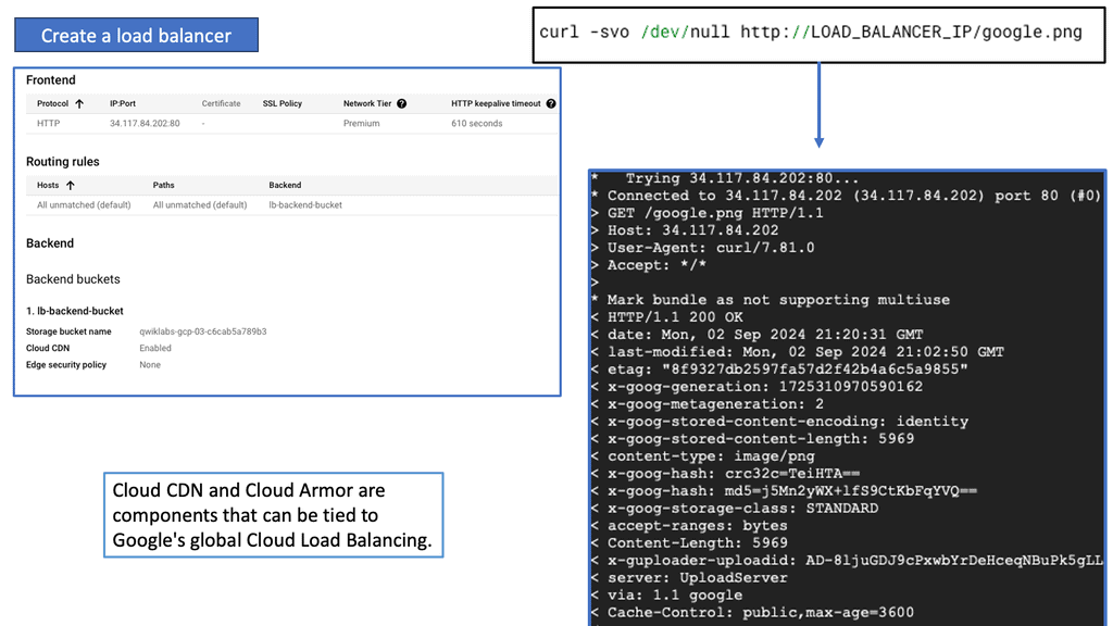
– **Detailed Reporting:** Generate in-depth reports that provide insights into network performance trends and potential areas for improvement.

#### Benefits of Using Cisco ThousandEyes for Data Center Performance

Implementing Cisco ThousandEyes in your data center can deliver a range of benefits that contribute to enhanced performance and reliability. Some of the key advantages include:

– **Proactive Issue Resolution:** By identifying potential problems before they escalate, ThousandEyes helps prevent downtime and ensures continuous service delivery.

– **Improved User Experience:** With optimized network performance, users enjoy faster, more reliable access to applications and services.

– **Cost Efficiency:** By reducing downtime and improving operational efficiency, ThousandEyes can help lower overall IT costs.

– **Scalability:** As your business grows, ThousandEyes can scale with you, providing consistent performance monitoring across expanding networks.

#### Real-World Applications

Many organizations have successfully leveraged Cisco ThousandEyes to boost their data center performance. For example, a global financial services company used ThousandEyes to monitor their network and quickly identify a latency issue affecting their trading platform. By resolving the issue promptly, they were able to maintain their competitive edge and deliver a seamless experience to their clients. Similarly, an e-commerce giant utilized ThousandEyes to ensure their website remained responsive during peak shopping seasons, resulting in increased customer satisfaction and sales.


Summary: Data Center Network Design

In today’s digital age, data centers are the backbone of countless industries, powering the storage, processing, and transmitting massive amounts of information. However, the efficiency and scalability of data center network design have become paramount concerns. In this blog post, we explored the challenges traditional data center network architectures face and delved into innovative solutions that are revolutionizing the field.
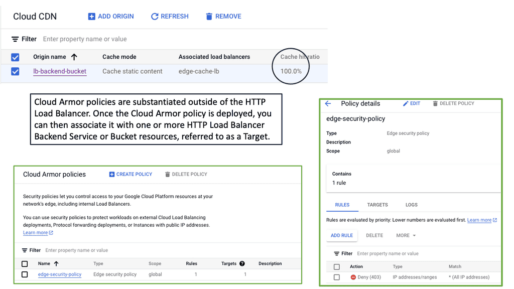
The Limitations of Traditional Designs

Traditional data center network designs, such as three-tier architectures, have long been the industry standard. However, these designs come with inherent limitations that hinder performance and flexibility. The oversubscription of network links, the complexity of managing multiple layers, and the lack of agility in scaling are just a few of the challenges that plague traditional designs.

Enter the Spine-and-Leaf Architecture

The spine-and-leaf architecture has emerged as a game-changer in data center network design. This approach replaces the hierarchical three-tier model with a more scalable and efficient structure. The spine-and-leaf design comprises spine switches, acting as the core, and leaf switches, connecting directly to the servers. This non-blocking, high-bandwidth architecture eliminates oversubscription and provides improved performance and scalability.

Embracing Software-Defined Networking (SDN)

Software-defined networking (SDN) is another revolutionary concept transforming data center network design. SDN abstracts the network control plane from the underlying infrastructure, allowing centralized network management and programmability. With SDN, data center administrators can dynamically allocate resources, optimize traffic flows, and respond rapidly to changing demands.

The Rise of Network Function Virtualization (NFV)

Network Function Virtualization (NFV) complements SDN by virtualizing network services traditionally implemented using dedicated hardware appliances. By decoupling network functions, such as firewalls, load balancers, and intrusion detection systems, from specialized hardware, NFV enables greater flexibility, scalability, and cost savings in data center network design.

Conclusion:

The landscape of data center network design is undergoing a significant transformation. Traditional architectures are being replaced by more scalable and efficient models like the spine-and-leaf architecture. Moreover, concepts like SDN and NFV empower administrators with unprecedented control and flexibility. As technology evolves, data center professionals must embrace these innovations and stay at the forefront of this paradigm shift.