Computer Networks

Computer Networking: Building a Strong Foundation for Success

Computer Networking

Computer networking has revolutionized how we communicate and share information in today's digital age. Computer networking offers many possibilities and opportunities, from the Internet to local area networks. This blog post will delve into the fascinating world of computer networking and discover its key components, benefits, and prospects.

Computer networking is essentially the practice of connecting multiple devices to share resources and information. It involves using protocols, hardware, and software to establish and maintain these connections. Understanding networking fundamentals, such as IP addresses, routers, and switches, is crucial for anyone venturing into this field.

The Birth of Networking: In the early days of computer networking, it was primarily used for military and scientific purposes. The advent of ARPANET in the late 1960s laid the foundation for what would eventually become the internet. This pioneering effort allowed multiple computers to communicate with each other, setting the stage for the interconnected world we know today.

The Internet Era Begins: The 1990s marked a significant turning point in computer networking with the emergence of the World Wide Web. Tim Berners-Lee's creation of the HTTP protocol and the first web browser fueled the rapid growth and accessibility of the internet. Suddenly, information could be shared and accessed with just a few clicks, transforming the way we gather knowledge, conduct business, and connect with others.

From Dial-Up to Broadband: Remember the days of screeching dial-up modems? As technology progressed, so did our means of connecting to the internet. The widespread adoption of broadband internet brought about faster speeds and more reliable connections. With the introduction of DSL, cable, and fiber-optic networks, users could enjoy seamless online experiences, paving the way for streaming media, online gaming, and the rise of cloud computing.

Wireless Networking and Mobility: Gone are the days of being tethered to a desktop computer. The advent of wireless networking technologies such as Wi-Fi and Bluetooth opened up a world of mobility and convenience. Whether it's connecting to the internet on our smartphones, laptops, or IoT devices, wireless networks have become an indispensable part of our daily lives, enabling us to stay connected wherever we go.

Highlights: Computer Networking

Network Components

Creating a computer network requires a lot of preparation and knowledge of the right components used. One of the first steps in computer networking is identifying what features to use and where to place them. This includes selecting the proper hardware, such as the Layer 3 routers, Layer 2 switches, and Layer 1 hubs if you are on an older network. Along with the right software, such as operating systems, applications, and network services. Or if any advanced computer networking techniques, such as virtualization and firewalling, are required.
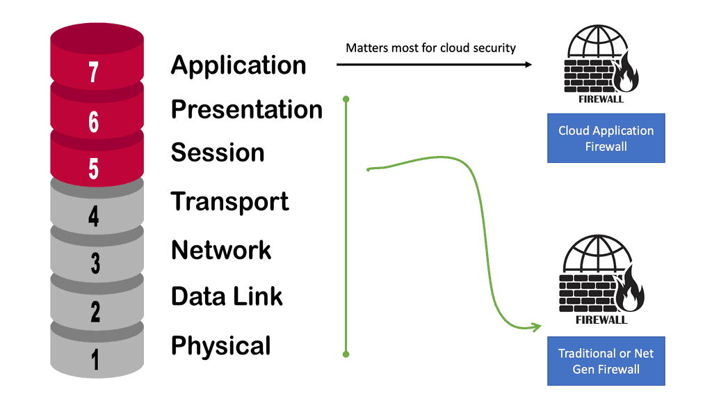
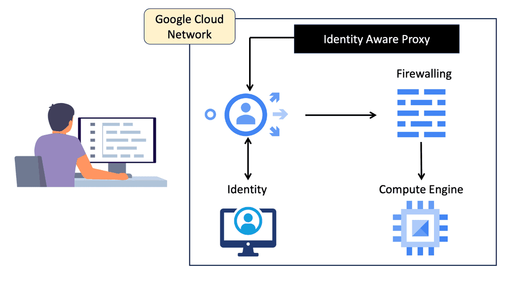
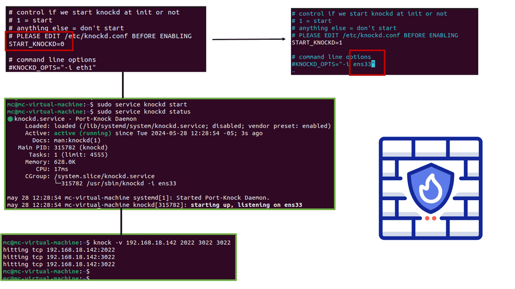
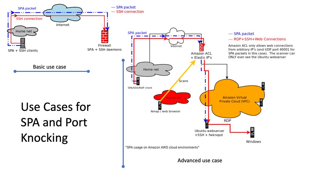
Diagram: Cloud Application Firewall.

Network Structure

Once the network components are identified, it’s time to plan the network’s structure. This involves deciding where each piece will be placed and how they will be connected. The majority of networks you will see today will be Ethernet-based. You will need a design process for more extensive networks. Still, for smaller networks, such as your home network, once physically connected, you are ready as all the network services are set up for you on the WAN router by the local service provider.

Network Design

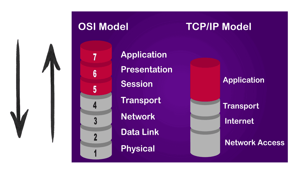
To embark on our journey into network design, it’s crucial to grasp the fundamental concepts. This section will cover topics such as network topologies, protocols, and the different layers of the OSI model. By establishing a solid foundation, you’ll be better equipped to make informed decisions in your network design endeavors.

Assessing Requirements and Goals

Before exploring the technical aspects of network design, it’s essential to identify your specific requirements and goals. This section will explore the importance of conducting a thorough needs analysis, considering factors such as scalability, security, and bandwidth. By aligning your network design with your objectives, you can build a robust and future-proof infrastructure.

Choosing the Right Equipment and Technologies

With a clear understanding of your requirements, it’s time to select the appropriate equipment and technologies for your network. We’ll delve into the world of routers, switches, firewalls, and wireless access points, discussing the criteria for evaluating different options. Additionally, we’ll explore emerging technologies like Software-Defined Networking (SDN) and Network Function Virtualization (NFV) that can revolutionize network design.

Designing for Efficiency and Redundancy

Efficiency and redundancy are vital aspects of network design that ensure reliable and optimized performance. This section will cover load balancing, fault tolerance, and network segmentation strategies. We’ll explore techniques like VLANs (Virtual Local Area Networks), link aggregation, and the implementation of redundant paths to minimize downtime and enhance network resilience.

Securing Your Network

Network security is paramount in an era of increasing cyber threats. This section will address best practices for securing your network, including firewalls, intrusion detection systems, and encryption protocols. We’ll also touch upon network access control mechanisms and the importance of regular updates and patches to safeguard against vulnerabilities.
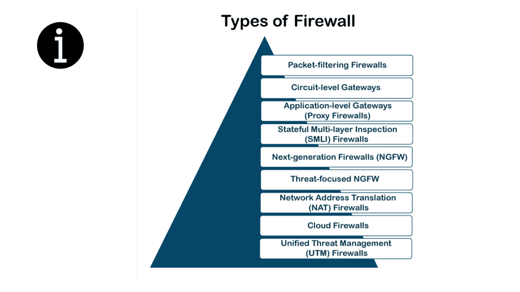
Firewall types
Diagram: Displaying the different firewall types.


Related: Additional links to internal content for pre-information:

  1. Data Center Topologies
  2. Distributed Firewalls
  3. Internet of Things Access Technologies
  4. LISP Protocol and VM Mobility.
  5. Port 179
  6. IP Forwarding
  7. Forwarding Routing Protocols
  8. Technology Insight for Microsegmentation
  9. Network Security Components
  10. Network Connectivity

Computer Networks

Key Computer Networking Discussion Points:


  • Introduction to computer networks and what is involved.

  • Highlighting the details of how you connect up networks.

  • Technical details on approaching computer networking and the importance of security.

  • Scenario: The main network devices: Are Layer 2 switches and Layer 3 routers.

  • The different types of protocols sued in computer networks.

Back to Basics: Computer Networks

A network is a collection of interconnected systems that share resources. Networks connect IoT (Internet of Things) devices, desktop computers, laptops, and mobile phones. A computer network will consist of standard devices such as APs, switches, and routers, the essential network components.

Network services

You can connect your network’s devices to other computer networks and the Internet, a global system of interconnected networks. So when we connect to the Internet, we secure the Local Area Network (LAN) to the Wide Area Network (WAN). As we move between computer networks, we must consider security.

You will need a security device between these segments for a stateful inspection firewall. You are probably running IPv4, so you will need a network service called Network Address Translation (NAT). IPv6, the latest version of the IP protocol, does not need NAT but may need a translation service to communicate with IPv4-only networks.

Network Address Translation

♦Types of Networks

There are various types of computer networks, each serving different purposes. Local Area Networks (LANs) connect devices within a limited geographical area, such as homes or offices. Wide Area Networks (WANs) span larger areas, connecting multiple LANs. The internet itself can be considered the most extensive WAN, connecting countless networks across the globe.

Computer networking brings numerous benefits to individuals and businesses. It enables seamless communication, file sharing, and resource access among connected devices. In industry, networking enhances productivity and collaboration, allowing employees to work together efficiently regardless of physical location. Moreover, networking facilitates company growth and expansion by providing access to global markets.

Computer Networking

Computer Networking Main Components


  •  A network is a collection of interconnected systems that share resources. The primary use case of a network was to share printers.

  • A network must offer a range of network services such as NAT.

  • Various types of computer networks, each serving different purposes. LAN vs WAN.

  • Protecting sensitive data, preventing unauthorized access, and mitigating potential threats are constant challenges.

Security and Challenges

With the ever-increasing reliance on computer networks, security becomes a critical concern. Protecting sensitive data, preventing unauthorized access, and mitigating potential threats are constant challenges. Network administrators employ various security measures such as firewalls, encryption, and intrusion detection systems to safeguard networks from malicious activities.

As technology continues to evolve, so does computer networking. Emerging trends such as cloud computing, the Internet of Things (IoT), and software-defined networking (SDN) are shaping the future of networking. The ability to connect more devices, handle massive amounts of data, and provide faster and more reliable connections opens up new possibilities for innovation and advancement.

Local Area Network

A Local Area Network (LAN) is a computer network that connects computers and other devices in a limited geographical area such as a home, school, office building, or closely positioned group of buildings. Ethernet cables typically connect LANs but may also be connected through wireless connections. LANs are usually used within a single organization or business but may connect multiple locations. The equipment in your LAN is in your control.

computer networking

Wide Area Network

Then, we have the Wide Area Network (WAN). In contrast to the LAN, a WAN is a computer network covering a wide geographical area, typically connecting multiple locations. Your LAN may only consist of Ethernet and a few network services.

However, a WAN may consist of various communications equipment, protocols, and media that provide access to multiple sites and users. WANs usually use private leased lines, such as T-carrier lines, to connect geographically dispersed locations. The equipment in the WAN is out of your control.
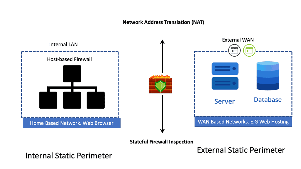
Computer Networks
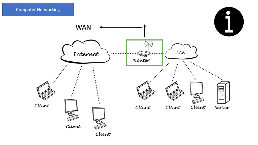
Diagram: Computer Networks with LAN and WAN.

LAN

WAN

  • LAN means local area network.

  •   Itconnect users and applications in close geographical proximity (same building).

  •  LANs use OSI Layer 1 and Layer 2 data connection equipment for transmission.

  •   LANs use local connections like Ethernet cables and wireless access points.

  • LANs are faster, because they span less distance and have less congestion.

  • LANs are good for private IoT networks, bot networks, and small business networks. LANs use OSI Layer 1 and Layer 2 data connection equipment for transmission.

  • WAN means wide area network.

  • Itconnect users and applications in geographically dispersed locations (across the globe).

  • WANs use Layer 1, 2, and 3 network devices for data transmission.

  • WANs use wide area connections like MPLS, VPNs, leased lines, and the cloud.

  • WANs are slightly slower, but that may not be perceived by your users.

  • WANs use Layer 1, 2, and 3 network deviceWANs are good for disaster recovery, applications with global users, and large corporate networks.s for data transmission.

Virtual Private Network ( VPN )

We use a VPN to connect LAN networks over a WAN. A virtual private network (VPN) is a secure and private connection between two or more devices over a public network such as the Internet. Its purpose is to provide fast, encrypted communication over an untrusted network.

VPNs are commonly used by businesses and individuals to protect sensitive data from prying eyes. One of the primary benefits of using a VPN is that it can protect your online privacy by masking your IP address and encrypting your internet traffic. This means that your online activities are hidden from your internet service provider (ISP), hackers, and other third parties who may be trying to eavesdrop on your internet connection.

Example: VPN Technology

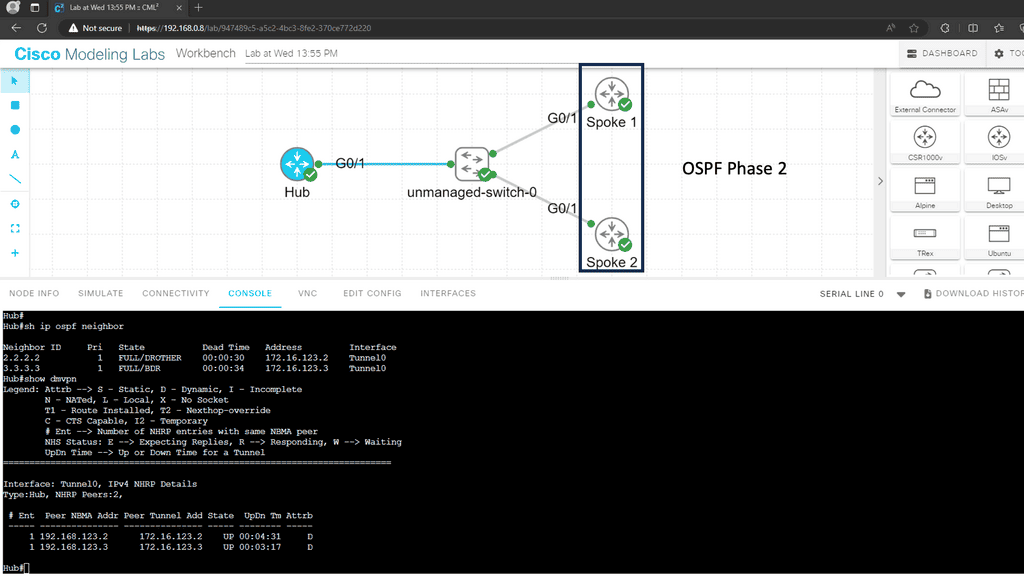
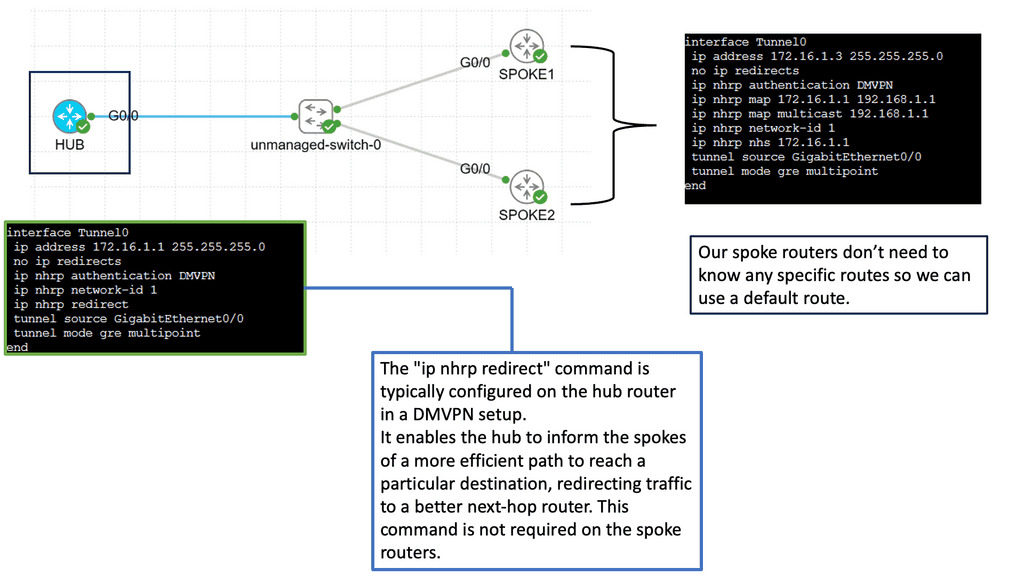
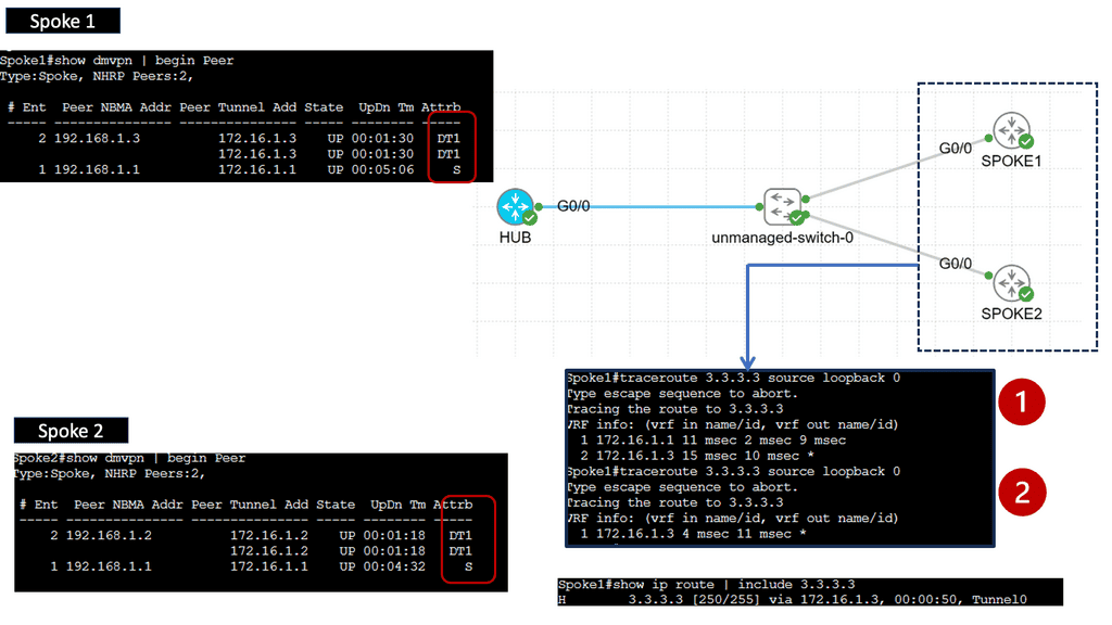
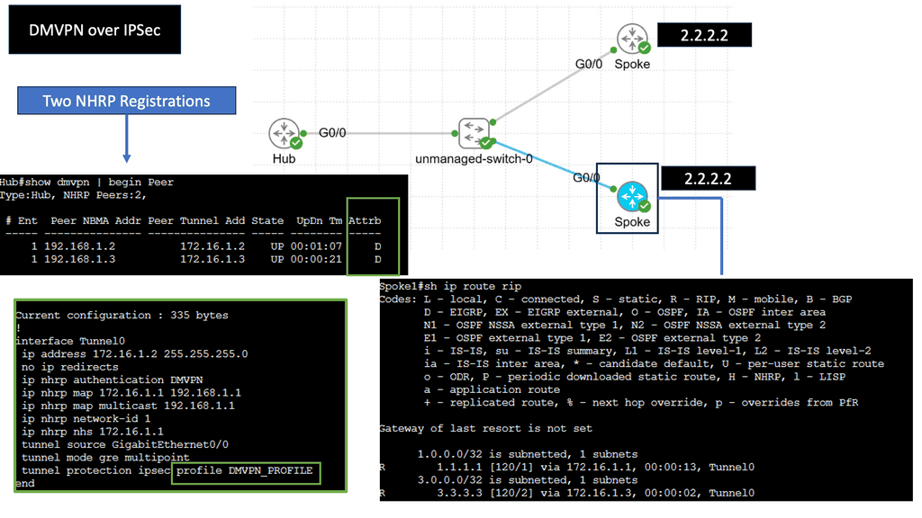
An example of a VPN technology is Cisco DMVPN. DMVPN operates in phases; there is DMVPN Pashe 1 to 3. For true hub and spoke, you would implement Phase 1; however, today, Phase 3 is the most popular, offering spoke-to-spoke tunnels. The screenshot below is an example of DMVPN Phase 1 running an OSPF network type of broadcast.

DMVPN

Computer Networking

Once the network’s components and structure have been determined, the next step is configuring computer networking. This involves setting up network parameters, such as IP addresses and subnets, and configuring routing tables.

Remember that security is paramount, especially when connecting to the Internet, an untrusted network with a lot of malicious activity. Firewalls help you create boundaries and secure zones for your networks. Different firewall types exist for the other network parts, making a layered approach to security.

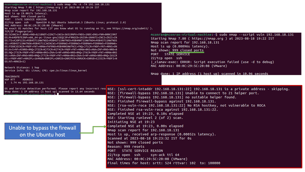
Once the computer networking is completed, the next step is to test the network. This can be done using tools such as network analyzers, which can detect any errors or issues present. You can conduct manual tests using Internet Control Message Protocol (ICMP) protocols, such as ping and traceroute. Testing for performance is only half of the pictures. It’s also imperative to regularly monitor the network for potential security vulnerabilities. So, you must have antivirus software, a computer firewall, and other endpoint security controls.

Finally, it’s critical to keep the network updated. This includes updating the operating system and applications and patching any security vulnerabilities as soon as possible. It’s also crucial to watch for upcoming or emerging technologies that may benefit the network.
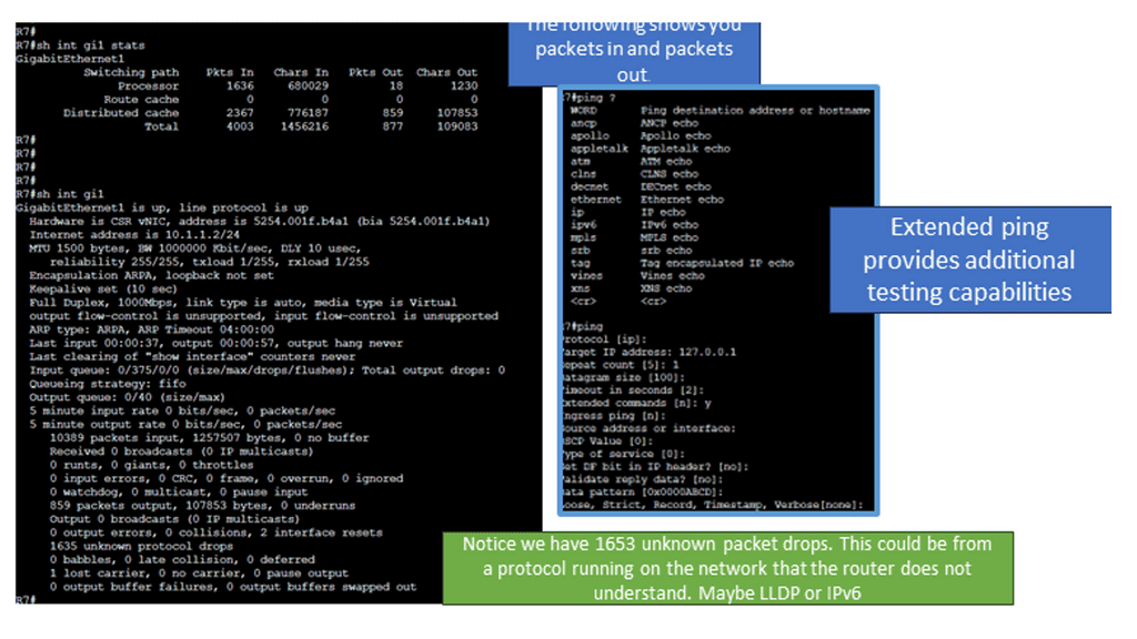
packet loss testing
Diagram: Packet loss testing.

Lab Guide: Endpoint Networking and Security

Address Resolution Protocol (ARP)

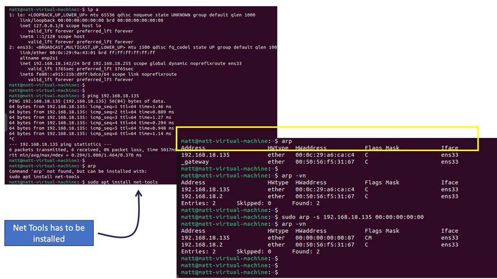
The first command you will want to become familiar with is arp

At its core, ARP is a protocol that maps an IP address to a corresponding MAC address. It enables devices within a local network to communicate with each other by resolving the destination MAC address for a given IP address. Devices store these mappings in an ARP table for efficient and quick communication.

Analysis: What you see are 5 column headers explained as follows:

  • Address: The IP address of a device on the network identified through the ARP protocol is resolved to the hostname.

  • HWtype: This describes the type of hardware facilitating the network connection. In this case, it is an ethernet rather than a Wi-Fi interface.

  • HW address: The MAC address assigned to the hardware interface responding to ARP requests.

  • Flags Mask: A hex value translated into ASCII defines how the interface was set.

  • Iface: Lists the interface’s name associated with the hardware and IP address.


Analysis: The output contains the same columns and information, with additional information about the contents of the cache. The -v flag is for verbose mode and provides additional information about the entries in the cache. Focus on the Address. The -n flag tells the command not to resolve the address to a hostname; the result is seeing the Address as an IP.

Note: The IP and Mac address returned is an additional VM running Linux in this network. This is significant because if a device is within the same subnet or layer two broadcast domain as a device identified by its local ARP cache, it will simply address traffic to the designated MAC address. In this way, if you can change the ARP cache, you can change where the device sends traffic within its subnet.

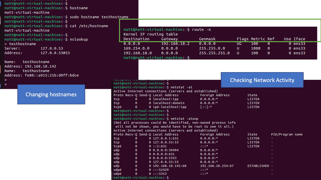
Locally, you can change the ARP cache directly by adding entries yourself.  See the screenshot above:

Analysis: Now you see the original entry and the entry you just set within the local ARP cache. When your device attempts to send traffic to the address 192.168.18.135, the packets will be addressed at layer 2 to the corresponding MAC address from this table. Generally, MAC address to IP address mappings are learned dynamically through the ARP network protocol activity, indicated by the “C” under the Flags Mask column. The CM reflects that the entry was manually added.

Note: Additional Information on ARP

  • ARP Request and Response

When a device needs to communicate with another device on the same network, it initiates an ARP request. The requesting device broadcasts an ARP request packet containing the target IP address for which it seeks the MAC address. The device with the matching IP address responds with an ARP reply packet, providing its MAC address. This exchange allows the requesting device to update its ARP table and establish a direct communication path.

  • ARP Cache Poisoning

While ARP serves a critical purpose in networking, it is vulnerable to attacks like ARP cache poisoning. In this type of attack, a malicious entity spoofs its MAC address, tricking devices on the network into associating an incorrect MAC address with an IP address. This can lead to various security issues, including interception of network traffic, data manipulation, and unauthorized access.

  • Address Resolution Protocol in IPv6

While ARP is predominantly used in IPv4 networks, IPv6 networks utilize a similar protocol called Neighbor Discovery Protocol (NDP). NDP performs functions identical to ARP but with additional features such as stateless address autoconfiguration and duplicate address detection. Although NDP differs from ARP in several ways, its purpose of mapping IP addresses to link-layer addresses remains the same.

Computer Networking & Data Traffic

Computer networking aims to carry data traffic so we can share resources. The first use case of computer networks was to share printers; now, we have a variety of use cases that evolve around data traffic. Data traffic can be generated from online activities such as streaming videos, downloading files, surfing the web, and playing online games. It is also generated from behind-the-scenes activities such as system updates and background and software downloads.

The Importance of Data Traffic

Data traffic is the amount transmitted over a network or the Internet. It is typically measured in bits, bytes, and packets per second. Data traffic can be both inbound and outbound. Inbound traffic is data coming into a network or computer, and outbound traffic is data leaving a network or computer. Inbound data traffic should be inspected by a security device, such as a firewall, which can either be at the network’s perimeter or on your computing device. At the same time, outbound traffic is generally unfiltered.

To keep up with the increasing demand, companies must monitor data traffic to ensure the highest quality of service and prevent network congestion. With the right data traffic monitoring tools and strategies, organizations can improve network performance and ensure their data is secure.


The Issues of Best Efforts or FIFO

Network devices don’t care what kind of traffic they have to forward. Ethernet frames are received by your switch, which looks for the destination MAC address before forwarding them. Your router does the same thing: it gets an IP packet, checks the routing table for the destination, and forwards the packet.

Would the frame or packet contain data from a user downloading the latest songs from Spotify or significant speech traffic from a VoIP phone? It doesn’t matter to the switch or router. This forwarding logic is called best effort or FIFO (First In, First Out). Sometimes, this can be an issue when applications are hungry for bandwidth. 

Example: Congestion

The serial link is likely congested when the host and IP phone transmit data and voice packets to the host and IP phone on the other side. Packets queued for transmission will not be indefinitely held by the router.

When the queue is full, how should the router proceed? Are data packets being dropped? Voice packets? If voice packets are dropped, there will be complaints about poor voice quality on the other end. If data packets are dropped, users may complain about slow transfer speeds.

You can change how the router or switch handles packets using QoS tools. For example, the router can prioritize voice traffic over data traffic.

The Role of QoS

Quality of Service (QoS) is a popular technique used in computer networking. QoS can segment applications so that different types will have different priority levels. For example, Voice traffic is often considered more critical than web surfing traffic. Especially as it is sensitive to packet loss. So, when there is congestion on the network, QoS allows administrators to prioritize network traffic so users have the best experience.

Quality of Service (QoS) refers to techniques and protocols prioritizing and managing network traffic. By allocating resources effectively, QoS ensures that critical applications and services receive the necessary bandwidth, low latency, and minimal packet loss while maintaining a stable network connection. This optimization process considers factors such as data type, network congestion, and the specific requirements of different applications.

Expedited Forwarding (EF)

Expedited Forwarding (EF) is a network traffic management model that provides preferential treatment to certain types of traffic. The EF model prioritizes traffic, specifically real-time traffic such as voice, video, and streaming media, over other types of traffic, such as email and web browsing. This allows these real-time applications to function more reliably and efficiently by reducing latency and jitter.

The EF model works by assigning a traffic class to each data packet based on the type of data it contains. The assigned class dictates how the network treats the packet. The EF model has two categories: EF for real-time traffic and Best Effort (BE) for other traffic. EF traffic is given preferential treatment, meaning it is prioritized over BE traffic, resulting in a higher quality of service for the EF traffic.

The EF model is an effective and efficient way to manage computer network traffic. By prioritizing real-time traffic, the EF model allows these applications to function more reliably, with fewer delays and a higher quality of service. Additionally, the EF model is more efficient, reducing the amount of traffic that needs to be managed by the network.

Lab Guide: QoS and Marking Traffic

TOS ( Type of Service )

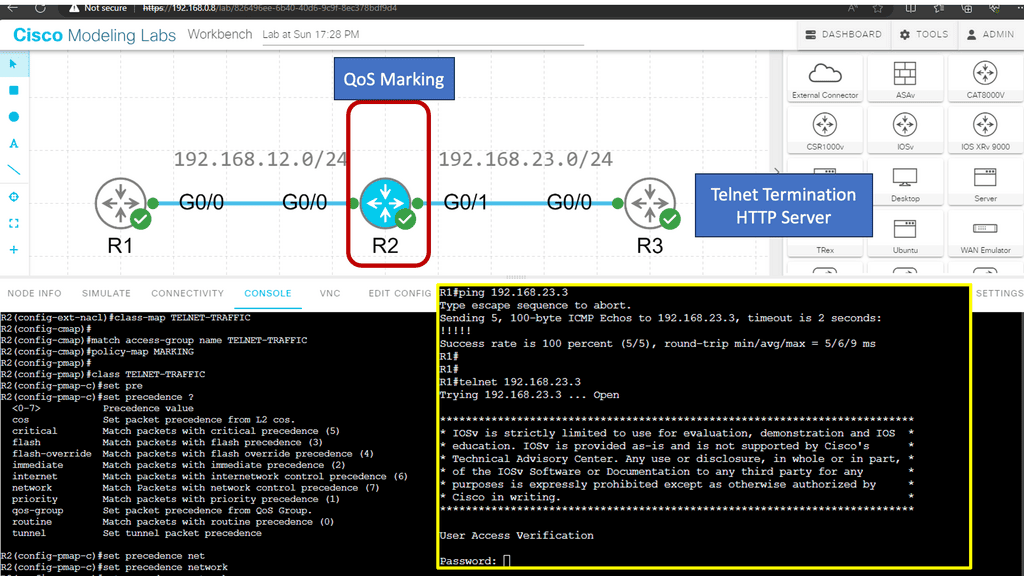
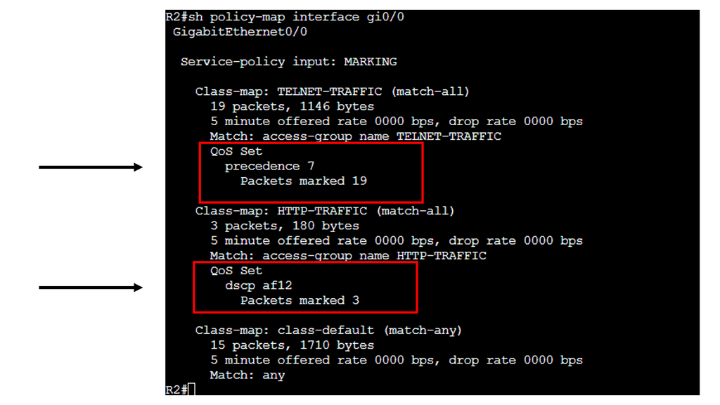
In this Lab, we’ll take a look at marking packets. Marking means we set the TOS (Type of Service) byte with an IP Precedence or DSCP value.

Marking and Classifcaiton take place on R2. R1 is the source of the ICMP and HTTP Traffic. R3 has an HTTP server installed. As traffic, both telnet and HTTP packets get sent from R1 and traverse R2, classification takes place.

Note:

To ensure each application gets the treatment it requires, we must implement QoS (Quality of Service). The first step when implementing QoS is classification,

QoS classification

We will mark the traffic and apply a QoS policy once it has been classified. Marking and configuring QoS policies are a whole different story, so we’ll stick to classification in this lesson.

On IOS routers, there are a couple of methods we can use for classification:

  • Header inspection
  • Payload inspection

We can use some fields in our headers to classify applications. For example, telnet uses TCP port 23, and HTTP uses TCP port 80. Using header inspection, you can look for:

  • Layer 2: MAC addresses
  • Layer 3: source and destination IP addresses
  • Layer 4: source and destination port numbers and protocol

QoS

♦Benefits of Quality of Service

A) Bandwidth Optimization:

One of the primary advantages of implementing QoS is the optimized utilization of available bandwidth. By classifying and prioritizing traffic, QoS ensures that bandwidth is allocated efficiently, preventing congestion and bottlenecks. This translates into smoother and uninterrupted network experiences, especially when multiple users or devices access the network simultaneously.

B) Enhanced User Experience:

With QoS, users can enjoy a seamless experience across various applications and services. Whether streaming high-quality video content, engaging in real-time online gaming, or participating in video conferences, QoS helps maintain low latency and minimal jitter, resulting in a smooth and immersive user experience.

♦Implementing Quality of Service

To implement QoS effectively, network administrators need to understand the specific requirements of their network and its users. This involves:

A) Traffic Classification:

Different types of network traffic require different levels of priority. Administrators can allocate resources by classifying traffic based on its nature and importance.

B) Traffic Shaping and Prioritization:

Once traffic is classified, administrators can prioritize it using various QoS mechanisms such as traffic shaping, packet queuing, and traffic policing. These techniques ensure critical applications receive the necessary resources while preventing high-bandwidth applications from monopolizing the network.

C) Monitoring and Fine-Tuning:

Regular monitoring and fine-tuning of QoS parameters are essential to maintain optimal network performance. By analyzing network traffic patterns and adjusting QoS settings accordingly, administrators can adapt to changing demands and ensure a consistently high level of service.

Computer Networking Components – Devices:

First, the devices. Media interconnect devices provide the channel over which the data travels from source to destination. Many devices are virtualized today, meaning they no longer exist as separate hardware units.

One physical device can emulate multiple end devices. In addition to having its operating system and required software, an emulated computer system operates as a separate physical unit. Devices can be further divided into endpoints and intermediary devices.

Endpoint: 

Endpoint is a device part of a computer network, including PCs, laptops, tablets, smartphones, video game consoles, and televisions. Endpoints can be physical hardware units, such as file servers, printers, sensors, cameras, manufacturing robots, and smart home components. Nowadays, we have virtualized endpoints.

Computer Networking Components – Intermediate Devices

Layer 2 Switches:

These devices enable multiple endpoints, such as PCs, file servers, printers, sensors, cameras, and manufacturing robots, to connect to the network. Switches allow devices to communicate on the same network. Switches attempt to forward messages from the sender so the destination can only receive them, unlike a hub that floods traffic out of all ports. The switch operates with MAC addresses and works at Layer 2 of the OSI model.

Usually, all the devices that connect to a single switch or a group of interconnected switches belong to a standard network. They can, therefore, exchange information directly with each other. If an end device wants to communicate with a device on a different network, it requires the “services” of a device known as a router. Routers connect other networks and work higher up in the OSI model at Layer 3. They use the IP protocol.

Routers

Routers’ primary function is to route traffic between computer networks. For example, you need a router to connect your office network to the Internet. Routers connect computer networks and intelligently select the best paths between them, and they hold destinations in what is known as a routing table. There are different routing protocols for different-sized networks, and each will have other routing convergence times.
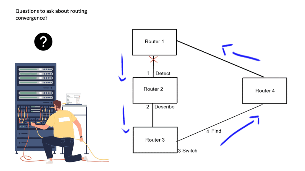
routing convergence
The well-known steps in routing convergence.

We recently combined Layer 2 and Layer 3 functionality. So we have a Layer 3 router with a Layer 2 switch module inserted, or we can have a multilayer switch that combines the functions of Layer 3 routing and Layer 2 switch functionality on a single device.
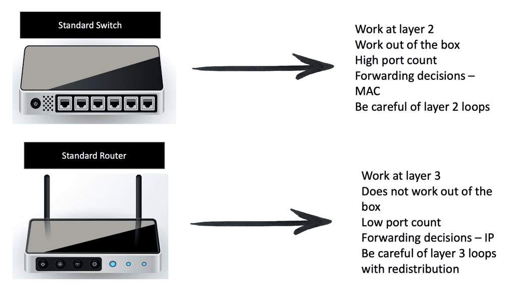
Computer Networks
Diagram: Computer Networks with Switch and Routers.

Wi-Fi access points

These devices allow wireless devices to connect. They usually connect to switches but can also be integrated into routers. My WAN router has everything in one box: Wi-Fi, Ethernet LAN, and network services such as NAT and WAN. Wi-Fi access points provide wireless internet access within a specified area.

Wi-Fi access points are typically found in coffee shops, restaurants, libraries, and airports in public settings. These access points allow anyone with a Wi-Fi-enabled device to access the Internet without needing additional hardware. 

WLAN controllers: 

WLAN controllers are devices used to automate the configuration of wireless access points. They provide centralized management of wireless networks and act as a gateway between wireless and wired networks. Administrators can monitor and manage the entire WLAN, set up security policies, and configure access points through the controller. WLAN controllers also authenticate users, allowing them to access the wireless network.

In addition, the WLAN controller can also detect and protect against malicious activities such as unauthorized access, denial-of-service attacks, and interference from other wireless networks. By using the controller, administrators can also monitor the usage of the wireless network and make sure that the network is secure.

Network firewalls:

Then, we have firewalls, which are the cornerstone of security. Depending on your requirements, there will be different firewall types. Firewalls range from basic packet filtering to advanced next-generation firewalls and come in virtual and physical forms.

Generally, a firewall monitors and controls incoming and outgoing traffic according to predefined security rules. The firewall will have a default rule set so that some firewall interfaces are more trusted than others, blankly restricting traffic from outside to inside, but you need to set up a policy for firewalls to work.

A firewall typically establishes a barrier between a trusted, secure internal network and another outside network, such as the Internet, which is assumed not to be secure or trusted. Firewalls are typically deployed in a layered approach, meaning multiple security measures are used to protect the network. Firewalls provide application, protocol, and network layer protection.
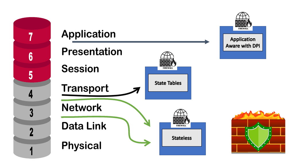
data center firewall
Diagram: The data center firewall.
  • Application layer protection:

The next layer is the application layer, designed to protect the network from malicious applications, such as viruses and malware. The application layer also includes software like firewalls to detect and block malicious traffic.

  • Protocol layer protection: 

The third layer is the protocol layer. This layer focuses on ensuring that the data traveling over a network is encrypted and that it is not allowed to be modified or corrupted in any way. This layer also includes authentication protocols that prevent unauthorized users from accessing the network.

  • Network Layer protection

Finally, the fourth layer is network layer protection. This layer focuses on controlling access to the network and ensuring that users cannot access resources or applications they are not authorized to use.

A network intrusion protection system (IPS): 

An IPS or IDS analyzes network traffic to search for signs that a particular behavior is suspicious or malicious. If the IPS detects such behavior, it can take protective action immediately. In addition, the IPS and firewall can work together to protect a network. So, if an IPS detects suspicious behavior, it can trigger a policy or rule for the firewall to implement.

An intrusion protection system can alert administrators of suspicious activity, such as attempts to gain unauthorized access to confidential files or data. Additionally, it can block malicious activity if necessary; it provides a layer of defense against malicious actors and cyber attacks. Intrusion protection systems are essential to any organization’s security plan.
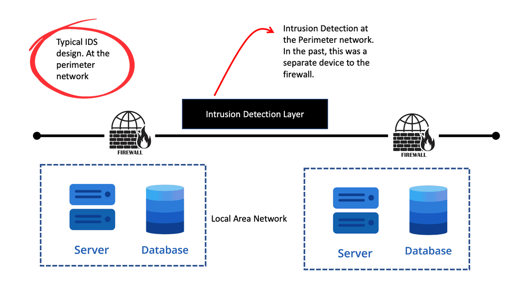
Cisco IPS
Diagram: Traditional Intrusion Detection. With Cisco IPS.

Computer Networking Components – Media

Next, we have the media. The media connects network devices. Different media have different characteristics, and selecting the most appropriate medium depends on the circumstances, including the environment in which the media is used and the distances that need to be covered.

The media will need some connectors. A connector makes it much easier to connect wired media to network devices. A connector is a plug attached to each end of the cable. RJ-45 connector is the most common type of connector on an Ethernet LAN.

Ethernet: Wired LAN technology.

The term Ethernet refers to an entire family of standards. Some standards define how to send data over a particular type of cabling and at a specific speed. Other standards define protocols or rules that the Ethernet nodes must follow to be a part of an Ethernet LAN. All these Ethernet standards come from the IEEE and include 802.3 as the beginning of the standard name.

Introducing Copper and Fiber

Ethernet LANs use cables for the links between nodes on a computer network. Because many types of cables use copper wires, Ethernet LANs are often called wired LANs. Ethernet LANs also use fiber-optic cabling, which includes a fiberglass core that devices use to send data using light. 

Materials inside the cable: UTP and Fiber

The most fundamental cabling choice concerns the materials used inside the cable to transmit bits physically: either copper wires or glass fibers. 

  • Unshielded twisted pair (UTP) cabling devices transmit data over electrical circuits via the copper wires inside the cable.
  • Fiber-optic cabling, the more expensive alternative, allows Ethernet nodes to send light over glass fibers in the cable’s center. 

Although more expensive, optical cables typically allow longer cabling distances between nodes. So you have UTP cabling in your LAN and Fiber-optic cabling over the WAN.

UTP and Fiber

The most common copper cabling for Ethernet is UTP. An unshielded twisted pair (UTP) is cheaper than the other two and is easier to install and troubleshoot. Many UTP-based Ethernet standards can use a cable length of up to 100 meters, which means that most Ethernet cabling in an enterprise uses UTP cables.

The distance from an Ethernet switch to every endpoint on a building’s floor will likely be less than 100m. In some cases, however, an engineer might prefer to use fiber cabling first for some links in an Ethernet LAN to reach greater distances.

Fiber Cabling

Then we have fiber-optic cabling, a glass core that carries light pulses and is immune to electrical interference. Fiber-optic cabling is typically used as a backbone between buildings. So fiber cables are high-speed transmission mediums. It contains tiny glass or plastic filaments as the medium to which light passes.

Cabling types: Multimode and Single Mode

There are two main types of fiber optic cables. We have single-mode fiber ( SMF) and multimode fiber ( MMF). Two implementations of fiber-optic include MMF for shorter distances and SMF for longer distances. Multimode improves the maximum distances over UTP and uses less expensive transmitters than single-mode. Standards vary; for instance, the criteria for 10 Gigabit Ethernet over Fiber allow for distances up to 400m, often allowing for connecting devices in different buildings in the same office park.

Network Services and Protocols

We need to follow these standards and the rules of the game. We also need protocols so we have the means to communicate. If you use your web browser, you use the HTTP protocol. If you send an email, you use other protocols, such as IMAP and SMTP.

A protocol establishes a set of rules that determine how data is transmitted between different devices in the network. The two protocols must talk to each other, such as HTTP at one end and HTTP at the other.

Consider protocol the same way you would speak the same language. We need to communicate in the same language. Then, we have standards that we need to follow for computer networking, such as the TCP/IP suite.

Types of protocols

We have different types of protocols. The following are the main types of protocols used in computer networking.

  • Communication Protocols

For example, we have routing protocols on our routers that help you forward traffic. This would be an example of a communication protocol that allows different devices to communicate with each other. Another example of a communication protocol would be instant messaging.

Instant messaging is instantaneous, text-based communication you probably have used on your smartphone. So here we have several instant messaging network protocols. Short Message Service (SMS): This communications protocol was created to send and receive text messages over cellular networks.  

  • Network Management

Network management protocols define and describe the various operating procedures of a computer network. These protocols affect multiple devices on a single network—including computers, routers, and servers—to ensure that each one and the network as a whole perform optimally.

  • Security Protocols

Security protocols, also called cryptographic protocols, ensure that the network and the data sent over it are protected from unauthorized users. Security protocols are implemented on more than just your network security devices. They are implemented everywhere. The standard functions of security network protocols include encryption: Encryption protocols protect data and secure areas by requiring users to input a secret key or password to access that information.

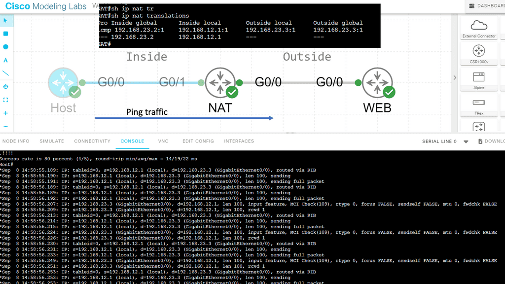
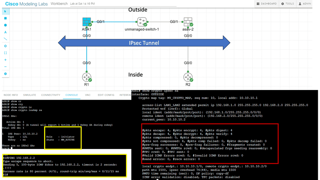
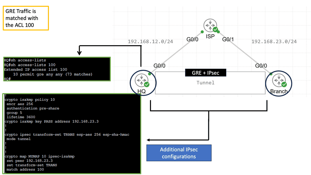
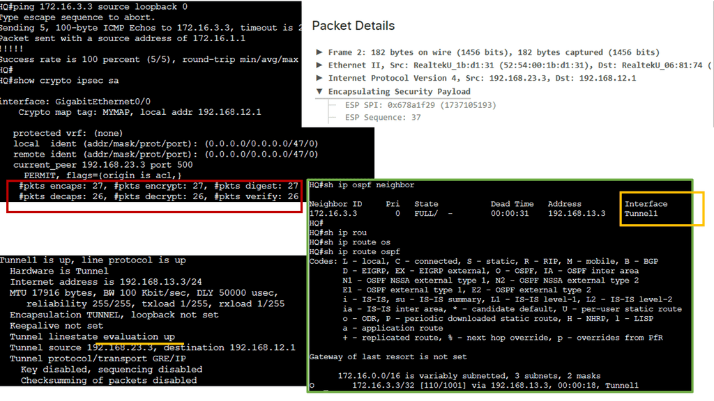
The following screenshot is an example of an IPsec tunnel offering end-to-end encryption. Notice that the first packet in the ping ( ICMP request ) was lost due to ARP working in the background. Five pings are sent, but only four are encapsulated/decapsulated.

Site to Site VPN

Characteristics of a network

Network Topology:

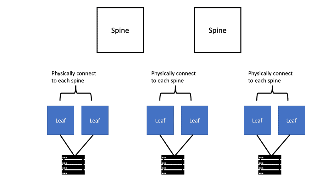
In a carefully designed network, data flows are optimized, and the network performs as intended based on the network topology. Network topology is the arrangement of a computer network’s elements (links, nodes, etc.). It can be used to illustrate a network’s physical and logical layout and how it functions. 

what is spine and leaf architecture

Bitrate or Bandwidth:

It is often referred to as bandwidth or speed in device configurations, sometimes considered speed. Bitrate measures the data rate in bits per second (bps) of a given link in the network. The number of bits transmitted in a second is more important than the speed at which one bit is transmitted over the link – which is determined by the physical properties of the medium that propagates the signal. Many link bit rates are commonly encountered today, including 1 and 10 gigabits per second (1 and 10 billion bits per second). Some links can reach 100 and even 400 gigabits per second.

Network Availability: 

Network availability is determined by several factors, including the type of network being used, the number of users, the complexity of the network, the physical environment, and the availability of network resources. Network availability should also be addressed in terms of redundancy and backup plans. Redundancy helps to ensure that the system is still operational even if one or more system components fail. Backup plans should also be in place in the event of a system failure.

A network’s availability is calculated based on the percentage of time it is accessible and operational. To calculate this percentage, divide the number of minutes the network is available by the total number of minutes it is available for over an agreed period and divide it by 100. In other words, availability is the ratio of uptime and full-time, expressed in percentage. 

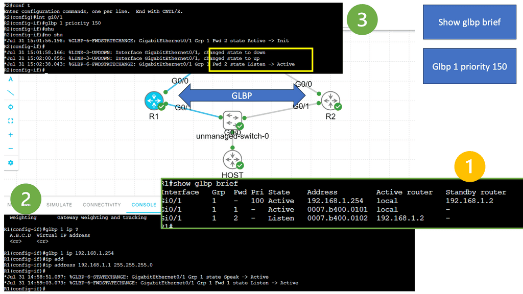
Gateway Load Balancer Protocol

Network High Availability: 

High availability is a critical component of a successful IT infrastructure. It ensures that systems and services remain available and accessible to users and customers. High availability is achieved by using redundancies, such as multiple servers, systems, and networks, to ensure that if one component fails, a backup component is available.

High availability is also achieved through fault tolerance, which involves designing systems that respond to failures without losing data or becoming unavailable. Various strategies, such as clustering, virtualization, and replication, can achieve high availability.

Network Reliability:

Network reliability can be achieved by implementing a variety of measures, often through redundancy. Redundancy is a crucial factor in ensuring a reliable network. Redundancy has multiple components to provide a backup in case of failure. Redundancy can include having multiple servers, routers, switches, and other hardware devices. Redundancy can also involve having numerous sources of power, such as various power supplies or batteries, and multiple paths for data to travel through the network.

For adequate network reliability, you also need to consider network monitoring. Network monitoring involves using software and hardware tools to monitor the network’s performance continuously. Monitoring can detect and alert administrators of potential performance issues or failures. We have a new term called Observability, which accurately reflects tracking in today’s environment.
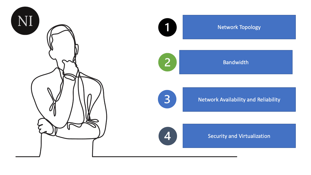
Network Characteristics
Diagram: Network Characteristics

Network Scalability:

A network’s scalability indicates how easily it can accommodate more users and data transmission requirements without affecting performance. Designing and optimizing a network only for the current conditions can make it costly and challenging to meet new needs when the network grows.

Several factors must be taken into account in terms of network scalability. First and foremost, the network must be designed with the expectation that the number of devices or users will increase over time. This includes hardware and software components, as the network must support the increased traffic. Additionally, the network must be designed to be flexible so that it can easily accommodate changes in traffic or user count. 

Network Security: 

Network security is protecting the integrity and accessibility of networks and data. It involves a range of protective measures designed to prevent unauthorized access, misuse, modification, or denial of a computer network and its processing data. These measures include physical security, technical security, and administrative security. A network’s security tells you how well it protects itself against potential threats.

The subject of security is essential, and defense techniques and practices are constantly evolving. The network infrastructure and the information transmitted over it should also be protected. Whenever you take actions to affect the network, you should consider security. An excellent way to view network security is to take a zero-trust approach.
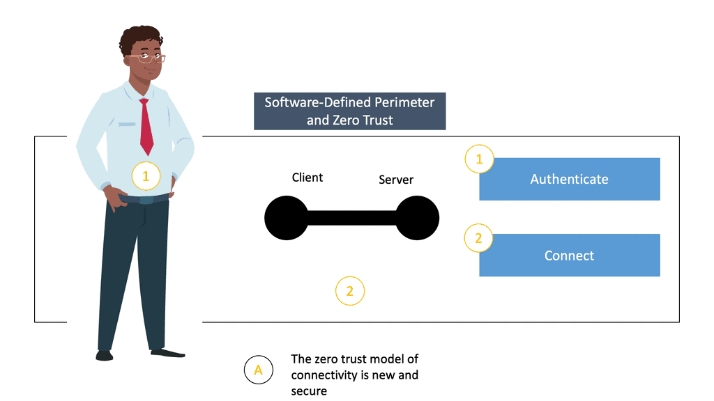
Software Defined Perimeter and Zero Trust

Virtualization: 

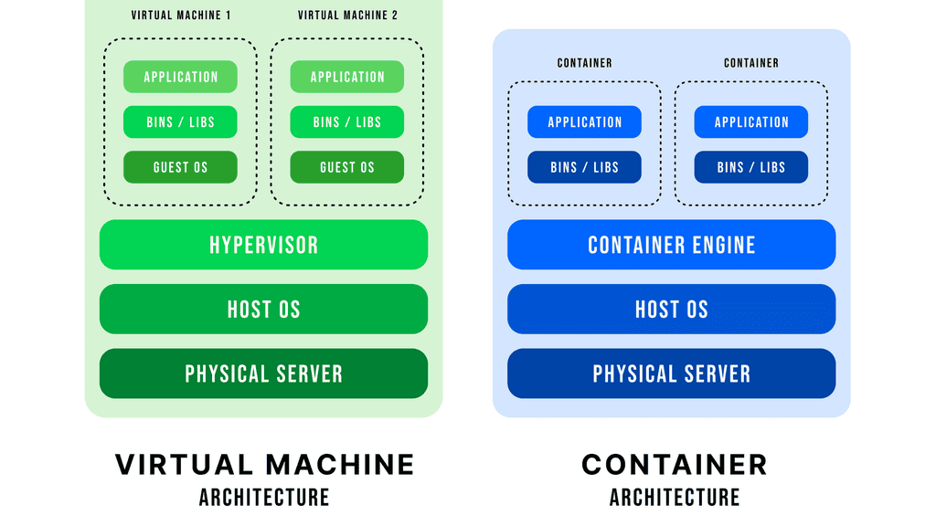
Virtualization can be done at the hardware, operating system, and application level. At the hardware level, physical hardware can be divided into multiple virtual machines, each running its operating system and applications.

At the operating system level, virtualization can run multiple operating systems on the same physical server, allowing for more efficient resource use. At the application level, multiple applications can run on the same operating system, allowing for better resource utilization and scalability. 

container based virtualization

Overall, virtualization can provide several benefits, including improved efficiency, utilization, flexibility, security, and scalability. It can consolidate and manage hardware or simplify application movement between different environments. Virtualization can also make it easier to manage other settings and provide better security by isolating various applications.

Computer Networking

Characteristics of a Network


  • Network Topology– It is the arrangement of a computer network’s elements (links, nodes, etc.)

  • Bitrate or Bandwidth– Bitrate measures the data rate in bits per second (bps) of a given link in the network.

  • Network Availability– It calculate based on the percentage of time it is accessible and operational..

  •  High Availability– It ensures that systems and services remain available and accessible to users and customers.

  • Reliability– It can be achieved by implementing a variety of measures, often through redundancy.

  • Scalability– Indicates how easily it can accommodate more users and data transmission needs without affecting performance.

  • Security– It protect the integrity, accessibility of networks & data, tells you how well it protects itself against potential threats..

  • Virtualization– It helps to improved efficiency, utilization & flexibility, as well as improved security and scalability.

Computer Networking and Network Topologies

Physical and logical topologies exist in networks. The physical topology describes the physical layout of the devices and cables. A physical topology may be the same in two networks but may differ in distances between nodes, physical connections, transmission rates, or signal types.

There are various types of physical topologies you may encounter in wired networks. Identifying the kind of cabling used is essential when describing the physical topology. Physical topology can be categorized into the following categories:

Bus Topology:

In a bus topology, every workstation is connected to a common transmission medium, a single cable called a backbone or bus. In a previous bus topology, computers and other network devices were connected to a central coaxial cable via connectors, resulting in direct connectivity.

Ring Topology:

In a ring topology, computers and other network devices are cabled in succession, with the last device connected to the first to form a circle or ring. There are two neighbors for every device in the network, and there are no direct connections between them. When one node sends data to another, it passes through each node between them until it reaches its destination.

  • Star Topology

A star topology is the most common physical topology, where network devices are connected to a central device through point-to-point connections. It is also known as the hub and spoke topology. A spoke device does not have a direct physical connection to another. This topology can also be called the extended star topology. A device with its spokes replaces one or more spoke devices in an extended star topology.

Mesh Topology

One device can be connected to more than one other in a mesh topology. Multiple paths are available for one node to reach another. Redundant links enhance reliability and self-healing. In a full mesh topology, all nodes are connected. In partial mesh, some nodes do not connect to all other nodes.

Introducing Switching Technologies

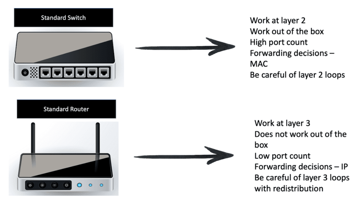
All Layer 2 devices connect to switches to communicate with one another. Switches work at layer two of the Open Systems Interconnection (OSI) model, the data link layer. Switches are ready to use right out of the box. In contrast to a router, a switch doesn’t require configuration settings by default. When you unbox the switch, it does not need to be configured to perform its role, which is to provide connectivity for all devices on your network. After putting power on the switch and connecting the systems, the switch will forward traffic to each connected device as needed.

Switch vs. Hubs

Moreover, you learned that switches had replaced hubs since they provide more advanced capabilities and are better suited to today’s computer networks. Advanced functionality includes filtering traffic by sending data only to the destination port (while a hub always sends data to all ports).

Full Duplex vs. Half Duplex

With a full duplex, both parties can talk and listen simultaneously, making it more efficient than half-duplex communication, where only one can speak simultaneously. Full duplex transmission is also more reliable since it is less likely to experience interference or distortion. Until switches became available, communication devices were only half-duplexed with hubs. A half-duplex device can send and receive simultaneously, but not simultaneously send and receive.

VLAN: Logical LANs

Virtual Local Area Networks (VLANs) are computer networks that divide a single physical local area network (LAN) into multiple logical networks. This partitioning allows for the segmentation of broadcast traffic, which helps to improve network performance and security.

VLANs enable administrators to set up multiple networks within a single physical LAN without needing separate cables or ports. These benefits businesses need to separate data and applications between various teams, departments, or customers.

In a VLAN, each segment is identified by a unique identifier or VLAN ID. The VLAN ID is used to associate traffic with a particular VLAN segment. For example, if a user needs to access an application on a different VLAN, the packet must be tagged with the VLAN ID of the destination segment to be routed correctly.

In the screenshot below, we have an overlay with VXLAN. VXLAN, short for Virtual Extensible LAN, is an overlay network technology that enables the creation of virtual Layer 2 networks over an existing Layer 3 infrastructure. It addresses traditional VLANs’ limitations by extending network virtualization’s scalability and flexibility. By encapsulating Layer 2 frames within UDP packets, VXLAN allows for creating up to 16 million logical networks, overcoming the limitations imposed by the 12-bit VLAN identifier field.
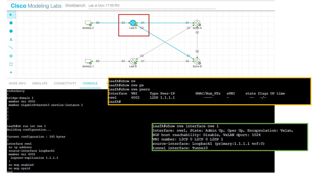
VXLAN
Diagram: Changing the VNI

VLANs also provide security benefits. A VLAN can help prevent malicious traffic from entering a segment by segmenting traffic into logical networks. This helps prevent attackers from gaining access to the entire network. Additionally, VLANs can isolate critical or confidential data from other users on the same network. VLANs can be implemented on almost any network, including wired and wireless networks. They can also be combined with other network technologies, such as routing and firewalls, to improve security further.

Overall, VLANs are powerful tools for improving performance and security in a local area network. With the right implementation and configuration, businesses can enjoy improved performance and better protection.

Switching Technologies

Switching Technologies


  •  Switch vs. Hubs- Switches replaced hubs since they provide more advanced capabilities and are better suited to today’s computer networks.

  • Full Duplex vs. Half Duplex- In Half Duplex mode, Sender can send the data and also can receive the data but one at a time. In Full Duplex mode, Sender can send the data and also can receive the data simultaneously.

  •  VLAN: Logical LANs- VLANs are a powerful tool to help improve performance and security in a local area network.

IP Routing Process

IP routing works by examining the IP address of each packet and determining where it should be sent. Routers are responsible for this task and use routing protocols such as RIP, OSPF, EIGRP, and BGP to decide the best route for each packet. In addition, each router contains a routing table, which includes information on the best path to a given destination.

When a router receives a packet, it looks up the destination in its routing table. If the destination is known, the router will make a forwarding decision based on the routing protocol. The router will use a default gateway to forward the packet if the destination is unknown.
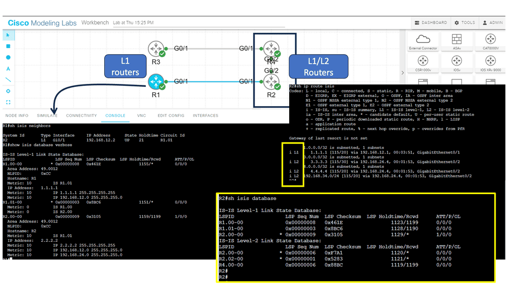
Routing Protocol
Diagram: Routing Protocol. ISIS.

To route packets successfully, routers must be configured appropriately and able to communicate with one another. They must also be able to detect any changes to the network, such as link failures or changes in network topology.

IP routing is essential to any network, ensuring packets are routed as efficiently as possible. Therefore, it is crucial to ensure that routers are correctly configured and maintained.
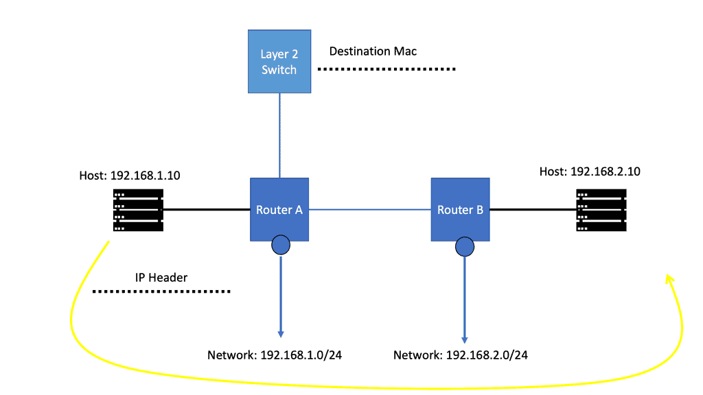
IP Forwarding Example
Diagram: IP Forwarding Example.

Routing Table

A routing table is a data table stored in a router or a networked computer that lists the possible routes a packet of data can take when traversing a network. The routing table contains information about the network’s topology and decides which route a packet should take when leaving the router or computer. Therefore, the routing table must be updated to ensure data packets are routed correctly.

The routing table usually contains entries that specify which interface to use when forwarding a packet. Each entry may have network destination addresses and associated metrics, such as the route’s cost or hop count. In addition to the destination address, each entry can include a subnet mask, a gateway address, and a list of interface addresses.

Routers use the routing table to determine which interface to use when forwarding packets. When a router receives a packet, it looks at the packet’s destination address and compares it to the entries in the routing table. Once it finds a match, it forwards the packet to the corresponding interface.

Lab Guide: Networking and Security

Routing Tables and Netstat

Routing tables are essentially databases stored within networking devices, such as routers. These tables contain valuable information about the available paths and destinations within a network. Each entry in a routing table consists of various fields, including the destination network address, next-hop address, and interface through which the data packet should be forwarded.

One of the fundamental features of Netstat is its ability to display active connections. Using the appropriate flags, you can view the list of established connections, their local and remote IP addresses, ports, and the protocol being used. This information is invaluable for identifying suspicious or unauthorized connections.

Get started by running the route command.

Analysis: Seem familiar? Yet another table with the following column headers:

    • Destination: This refers to the destination of traffic from this device. The default refers to anything not explicitly set.

    • Gateway: The next hop for traffic headed to the specific destination.

    • Genmask: The netmask of the destination.

      Note: For more detailed explanations of all the columns and results, run man route.

Run netstat to get a stream of information relating to network socket connections and UNIX domain sockets.

Note: UNIX domain sockets are a mechanism that allows processes local to the devices to exchange data.

  1. To clean this up, you can view just the network traffic using. netstat -at.

    • -a displays all ports, including IPV4 & IPV6

    • -t displays only TCP sockets

Analysis: When routes are created in different ways, they display differently. In the most recent rule, you can see that no metric is listed, and the scope is different from the other automatic routes. That is the kind of information we can use for detection.

The route table will send traffic to the designated gateway regardless of the route’s validity. Threat actors can use this to intercept traffic destined for another location, making it a crucial place to look for indicators of compromise.

How Routing Tables Work:

Routing tables utilize various routing protocols, such as OSPF (Open Shortest Path First) or BGP (Border Gateway Protocol), to gather information about network topology and make informed decisions about the best paths for data packets. These protocols exchange routing information between routers, ensuring that each device has an up-to-date understanding of the network’s structure.

Routing Table Entries and Metrics:

Each entry in a routing table contains specific metrics that determine the best path for forwarding packets. Metrics can include hop count, bandwidth, delay, or reliability. By evaluating these metrics, routers can select the most optimal route based on network conditions and requirements.

Summary: Computer Networking

It’s the backbone of modern communication, from browsing the internet to sharing files across devices. In this blog post, we delved into the fascinating world of computer networking, exploring its key concepts, benefits, and future prospects.

Section 1: What is Computer Networking?

Computer networking refers to connecting multiple computers and devices to facilitate data sharing and communication. It involves hardware components such as routers, switches, cables, and software protocols that enable seamless data transmission.

Section 2: The Importance of Computer Networking

Computer networking has revolutionized how we work, communicate, and access information. It enables efficient collaboration, allowing individuals and organizations to share resources, communicate in real-time, and access data from anywhere in the world. Whether a small local network or a global internet connection, networking plays a pivotal role in our digital lives.

Section 3: Types of Computer Networks

There are various types of computer networks, each serving different purposes. Local Area Networks (LANs) connect devices such as homes, offices, or schools within a limited area. Wide Area Networks (WANs) span larger geographical areas, connecting multiple LANs together. Additionally, there are Metropolitan Area Networks (MANs), Wireless Networks, and the vast Internet itself.

Section 4: Key Concepts in Computer Networking

To understand computer networking, you must familiarize yourself with key concepts like IP addresses, protocols (such as TCP/IP), routing, and network security. These concepts form the foundation of how data is transmitted, received, and protected within a network.

Section 5: The Future of Computer Networking

As technology advances, so does the world of computer networking. Emerging trends such as the Internet of Things (IoT), 5G networks, and cloud computing are reshaping the networking landscape. These developments promise faster speeds, increased connectivity, and enhanced security, paving the way for a more interconnected future.

Conclusion:

In conclusion, computer networking is a fascinating field that underpins our digital world. Its importance cannot be overstated, as it enables seamless communication, resource sharing, and global connectivity. Understanding the key concepts and staying updated with the latest trends in computer networking will empower individuals and organizations to make the most of this ever-evolving technology.

SD WAN Overlay

SD WAN Overlay

SD WAN Overlay

In today's digital age, businesses rely on seamless and secure network connectivity to support their operations. Traditional Wide Area Network (WAN) architectures often struggle to meet the demands of modern companies due to their limited bandwidth, high costs, and lack of flexibility. A revolutionary SD-WAN (Software-Defined Wide Area Network) overlay has emerged to address these challenges, offering businesses a more efficient and agile network solution. This blog post will delve into SD-WAN overlay, exploring its benefits, implementation, and potential to transform how businesses connect.

SD-WAN employs the concepts of overlay networking. Overlay networking is a virtual network architecture that allows for the creation of multiple logical networks on top of an existing physical network infrastructure. It involves the encapsulation of network traffic within packets, enabling data to traverse across different networks regardless of their physical locations. This abstraction layer provides immense flexibility and agility, making overlay networking an attractive option for organizations of all sizes.

- Scalability: One of the key advantages of overlay networking is its ability to scale effortlessly. By decoupling the logical network from the underlying physical infrastructure, organizations can rapidly deploy and expand their networks without disruption. This scalability is particularly crucial in cloud environments or scenarios where network requirements change frequently.

- Security and Isolation: Overlay networks provide enhanced security by isolating different logical networks from each other. This isolation ensures that data traffic remains segregated and prevents unauthorized access to sensitive information. Additionally, overlay networks can implement advanced security measures such as encryption and access control, further fortifying network security.

Highlights: SD WAN Overlay

Understanding Overlay Networking

Overlay networking is a revolutionary approach to network design that enables the creation of virtual networks on top of existing physical networks. By abstracting the underlying infrastructure, overlay networks provide a flexible and scalable solution to meet the dynamic demands of modern applications and services. Whether in cloud environments, data centers, or even across geographically dispersed locations, overlay networking opens up a world of possibilities.

Overlay networks act as a virtual layer on the physical network infrastructure. They enable the creation of logical connections independent of the physical network topology. In the context of SD-WAN, overlay networks facilitate the seamless integration of multiple network connections, including MPLS, broadband, and LTE, into a unified and efficient network.

The advantages of overlay networking are manifold:

– First, it allows for seamless network segmentation, enabling different applications or user groups to operate in isolation while sharing the same physical infrastructure. This enhances security and simplifies network management.

– Secondly, overlay networks facilitate deploying advanced network services such as load balancing, firewalling, and encryption without complex changes to the underlying network infrastructure. This abstraction level empowers organizations to adapt and respond rapidly to evolving business needs.

**So, what exactly is an SD-WAN overlay?**

In simple terms, it is a virtual layer added to the existing network infrastructure. These network overlays connect different locations, such as branch offices, data centers, and the cloud, by creating a secure and reliable network.

1. Tunnel-Based Overlays:

One of the most common types of SD-WAN overlays is tunnel-based overlays. This approach encapsulates network traffic within a virtual tunnel, allowing it to traverse multiple networks securely. Tunnel-based overlays are typically implemented using IPsec or GRE (Generic Routing Encapsulation) protocols. They offer enhanced security through encryption and provide a reliable connection between the SD-WAN edge devices.

Example Technology: IPSec and GRE

Organizations can achieve enhanced network security and improved connectivity by combining GRE and IPSec. The integration allows for creating secure tunnels between networks, ensuring that data transmitted between them remains protected from potential threats. This combination also enables the establishment of Virtual Private Networks (VPNs), enabling secure remote access and seamless connectivity for geographically dispersed teams.

By encrypting GRE tunnels, IPsec provides secure VPN tunnels. This approach offers many benefits, including support for dynamic IGP routing protocols, non-IP protocols, and IP multicast. Furthermore, the headend IPsec termination points can support QoS policies and deterministic routing metrics.

There is built-in redundancy due to the pre-established primary and backup GRE over IPsec tunnels. Static IP addresses are required for the headend site, but dynamic IP addresses are permitted for the remote sites. To differentiate primary tunnels from backup tunnels, routing metrics can be modified slightly to favor one or the other.

GRE with IPsec ipsec plus GRE

2. Segment-Based Overlays:

Segment-based overlays are designed to segment the network traffic based on specific criteria such as application type, user group, or location. This allows organizations to prioritize critical applications and allocate network resources accordingly. By segmenting the traffic, SD-WAN can optimize the performance of each application and ensure a consistent user experience. Segment-based overlays are particularly beneficial for businesses with diverse network requirements.

3. Policy-Based Overlays:

Policy-based overlays enable organizations to define rules and policies that govern the behavior of the SD-WAN network. These overlays use intelligent routing algorithms to dynamically select the most optimal path for network traffic based on predefined policies. By leveraging policy-based overlays, businesses can ensure efficient utilization of network resources, minimize latency, and improve overall network performance.

4. Hybrid Overlays:

Hybrid overlays combine the benefits of both public and private networks. This overlay allows organizations to utilize multiple network connections, including MPLS, broadband, and LTE, to create a robust and resilient network infrastructure. Hybrid overlays intelligently route traffic through the most suitable connection based on application requirements, network availability, and cost. Businesses can achieve high availability, cost-effectiveness, and improved application performance by leveraging mixed overlays.

5. Cloud-Enabled Overlays:

As more businesses adopt cloud-based applications and services, seamless connectivity to cloud environments becomes crucial. Cloud-enabled overlays provide direct and secure connectivity between the SD-WAN network and cloud service providers. These overlays ensure optimized performance for cloud applications by minimizing latency and providing efficient data transfer. Cloud-enabled overlays simplify the management and deployment of SD-WAN in multi-cloud environments, making them an ideal choice for businesses embracing cloud technologies.

**Challenge: The traditional network**

The networks we depend on for business are sensitive to many factors that can result in a slow and unreliable experience. Latency, which refers to the time between a data packet being sent and received, or round-trip time, which is the time it takes for the packet to be sent and for it to get a reply, can be experienced.

We can also experience jitter, the variance in the time delay between data packets in the network, which is a “disruption” in the sending and receiving packets. We have fixed-bandwidth networks that can experience congestion. For example, with five people sharing the same Internet link, each could experience a stable and swift network. Add another 20 or 30 people onto the same link, and the experience will be markedly different.

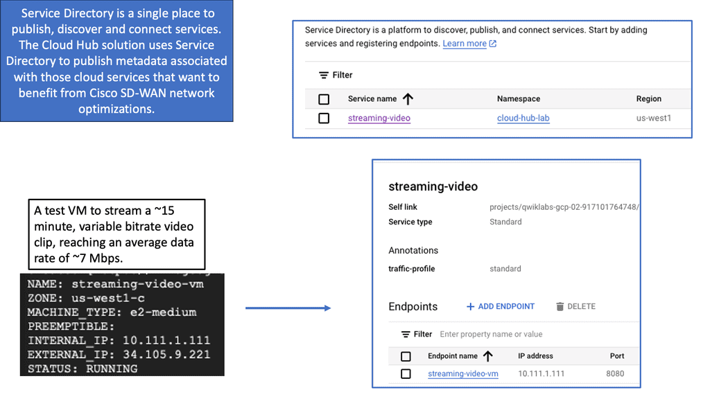
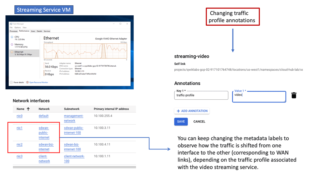
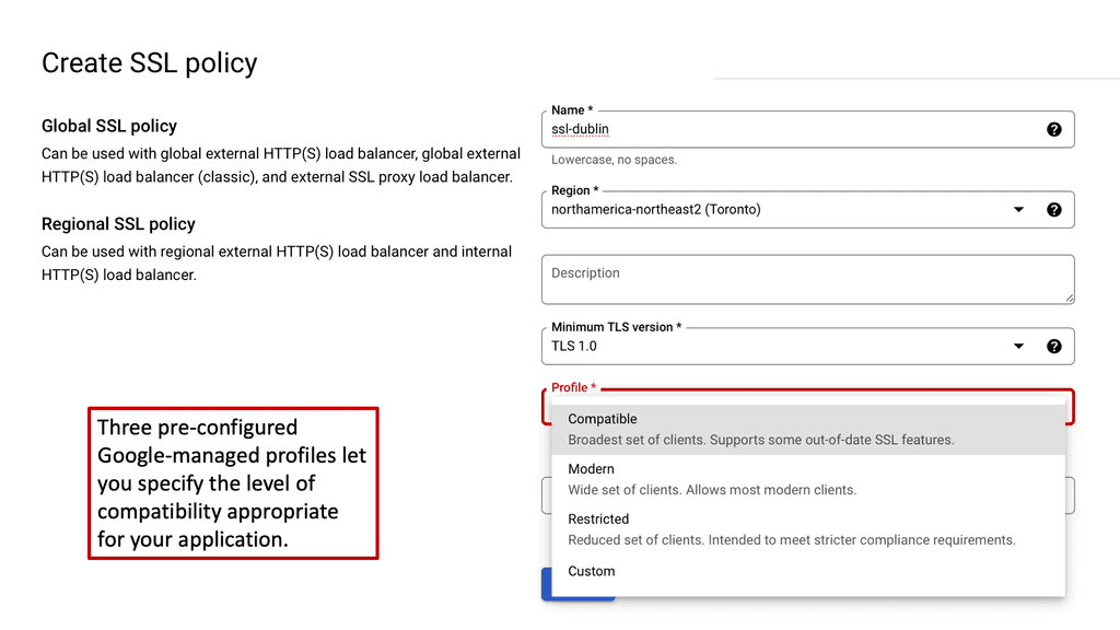
Google Cloud & SD WAN

SD WAN Cloud Hub

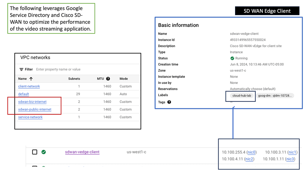
Google Cloud is renowned for its robust infrastructure, scalability, and advanced services. By integrating SD-WAN with Google Cloud, businesses can tap into this powerful ecosystem. They gain access to Google’s global network, enabling optimized routing and lower latency. Additionally, the scalability and flexibility of Google Cloud allow organizations to adapt to changing network demands seamlessly.

Key Advantages:

When SD-WAN Cloud Hub is integrated with Google Cloud, it unlocks a host of advantages. Firstly, it enables organizations to seamlessly connect their branch offices, data centers, and cloud resources, providing a unified network fabric. This integration optimizes traffic flow and enhances application performance, ensuring a consistent user experience.

Key Features and Benefits:

Intelligent Traffic Steering: SD-WAN Cloud Hub with Google Cloud allows organizations to intelligently steer traffic based on application requirements, network conditions, and security policies. This dynamic traffic routing ensures optimal performance and minimizes latency.

Simplified Network Management: The centralized management platform of SD-WAN Cloud Hub simplifies network configuration, monitoring, and troubleshooting. Integration with Google Cloud provides a unified view of the entire network infrastructure, streamlining operations and reducing complexity.

Enhanced Security: SD-WAN Cloud Hub leverages Google Cloud’s security features, such as Cloud Armor and Cloud Identity-Aware Proxy, to protect network traffic and ensure secure communication between branches, data centers, and the cloud.

VPN and Overlay technologies

  • Performance-Based Routing & DMVPN 

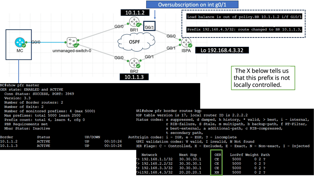
Performance-based routing is a dynamic routing technique beyond traditional static routing protocols. It leverages real-time data and network monitoring to make intelligent routing decisions based on latency, bandwidth availability, and network congestion. By constantly analyzing network conditions, performance-based routing algorithms can adapt and reroute traffic to the most efficient paths, ensuring speedy and reliable data transmission.

  • DMVPN Phase 3

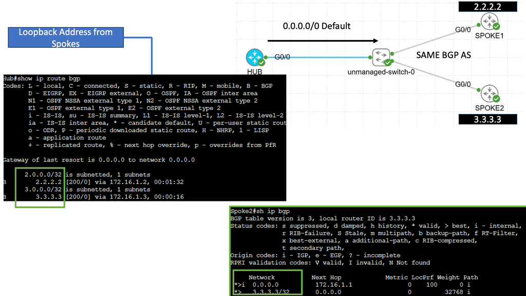
DMVPN Phase 3 is the latest iteration of the DMVPN technology, designed to address the limitations of its predecessors. It introduces significant improvements in scalability, routing protocol support, and encryption capabilities. By utilizing multipoint GRE tunnels, DMVPN Phase 3 enables efficient and dynamic communication between multiple sites securely and efficiently.

One of DMVPN Phase 3’s key advantages is its scalability. The introduction of the NHRP (Next Hop Resolution Protocol) redirect allows for the dynamic and efficient allocation of network resources, making it an ideal solution for large-scale deployments. Additionally, DMVPN Phase 3 supports a wide range of routing protocols, including OSPF, EIGRP, and BGP, providing network administrators with flexibility and ease of integration.

Multipoint GRE (mGRE) is an underlying technology that plays a crucial role in DMVPN’s functionality. It enables the establishment of multiple tunnels over a single GRE interface, maximizing network resource utilization. Encapsulating packets in GRE headers, mGRE facilitates traffic routing between remote sites, creating a secure and efficient communication path.

Configuring spokes to terminate multiple headends at one or more hub locations can achieve redundancy. Cryptographic attributes are typically mapped to the tunnel initiated by the remote peer through IPsec tunnel protection..

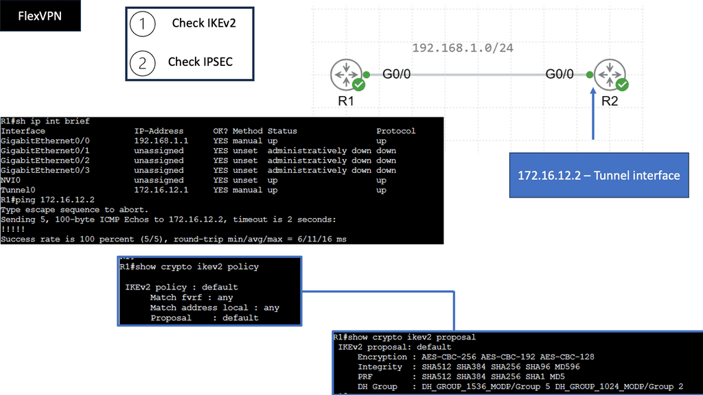
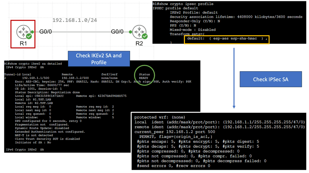
FlexVPN Site-to-Site Smart Defaults

FlexVPN Site-to-Site Smart Defaults is a feature designed to simplify and streamline the configuration process of site-to-site VPN connections. It provides a set of predefined default values for various parameters, eliminating the need for complex manual configurations. Network administrators can save time and effort by leveraging these smart defaults while ensuring robust security.

One key advantage of FlexVPN Site-to-Site Smart Defaults is its ease of use. Network administrators can quickly deploy secure site-to-site VPN connections without extensive knowledge of complex VPN configurations. The predefined defaults ensure that essential security features are automatically enabled, minimizing the risk of misconfigurations and vulnerabilities.

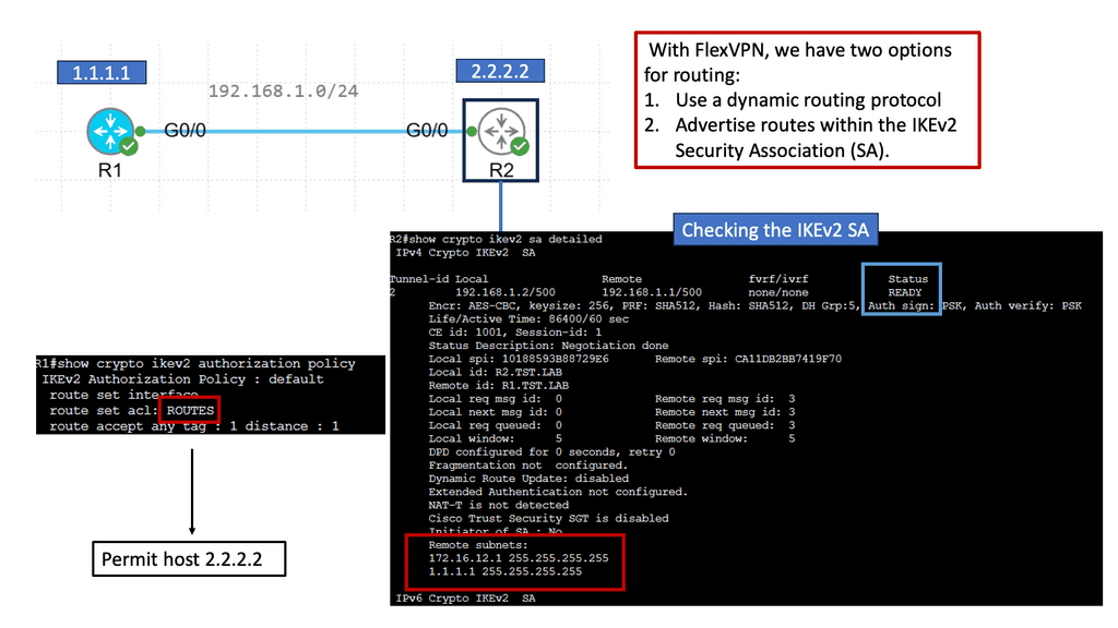
FlexVPN IKEv2 Routing

FlexVPN IKEv2 routing is a robust routing protocol that combines the flexibility of FlexVPN with the security of IKEv2. It allows for dynamic routing between different sites and simplifies the management of complex network infrastructures. By utilizing the power of cryptographic security and advanced routing techniques, FlexVPN IKEv2 routing ensures secure and efficient communication across networks.

FlexVPN IKEv2 routing offers numerous benefits, making it a preferred choice for network administrators. Firstly, it provides enhanced scalability, allowing networks to grow and adapt to changing requirements quickly. Additionally, the protocol ensures end-to-end security by encapsulating data within secure tunnels, protecting it from unauthorized access. Moreover, FlexVPN IKEv2 routing supports multipoint connectivity, enabling seamless communication between multiple sites.

**Transport Fabric Technology**

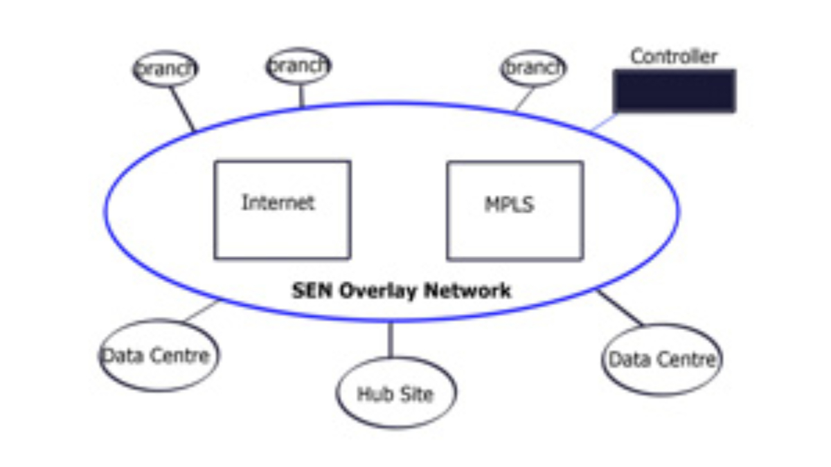
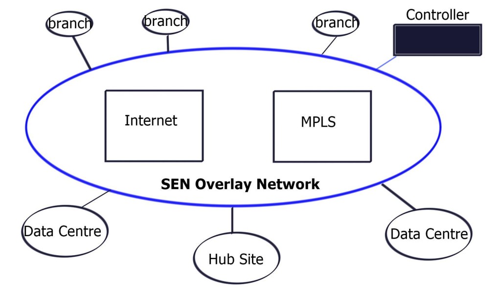
SD-WAN leverages transport-independent fabric technology to connect remote locations. This is achieved by using overlay technology. The SDWAN overlay works by tunneling traffic over any transport between destinations within the WAN environment.
This gives authentic flexibility to routing applications across any network portion regardless of the circuit or transport type. This is the definition of transport independence. Having a fabric SDWAN overlay network means that every remote site, regardless of physical or logical separation, is always a single hop away from another. DMPVN works based on transport agnostic design.

SD-WAN vs Traditional WAN

SD-WAN overlays offer several advantages over traditional WANs, including improved scalability, reduced complexity, and better control over traffic flows. They also provide better security, as each site is protected by its dedicated security protocols. Additionally, SD-WAN overlays can improve application performance and reliability and reduce latency.

Key Point: SD-WAN abstracts the underlay

With SD-WAN, the virtual WAN overlays are abstracted from the physical device’s underlay. Therefore, the virtual WAN overlays can take on topologies independent of each other without being pinned to the configuration of the underlay network. SD-WAN changes how you map application requirements to the network, allowing for the creation of independent topologies per application.

For example, mission-critical applications may use expensive leased lines, while lower-priority applications can use inexpensive best-effort Internet links. This can all change on the fly if specific performance metrics are unmet.

Previously, the application had to match and “fit” into the network with the legacy WAN, but with an SD-WAN, the application now controls the network topology. Multiple independent topologies per application are a crucial driver for SD-WAN.

Example Technology: PTP GRE

Point to Point GRE, or Generic Routing Encapsulation, is a protocol that encapsulates and transports various network layer protocols over an IP network. Providing a virtual point-to-point link enables secure and efficient communication between remote networks. Point to Point GRE offers a flexible and scalable solution for organizations seeking to establish secure connections over public or private networks.

SD-WAN combines transports, SDWAN overlay, and underlay

Look at it this way. With an SD-WAN topology, there are different levels of networking. There is an underlay network, the physical infrastructure, and an SDWAN overlay network. The physical infrastructure is the router, switches, and WAN transports; the overlay network is the virtual WAN overlays.

The SDWAN overlay presents a different network to the application. For example, the voice overlay will see only the voice overlay. The logical virtual pipe the overlay creates and the application sees differs from the underlay.

An SDWAN overlay network is a virtual or logical network created on top of an existing physical network. The internet, which connects many nodes via circuit switching, is an example of an SDWAN overlay network. An overlay network is any virtual layer on top of physical network infrastructure.

  • Consider an SDWAN overlay as a flexible tag.

This may be as simple as a virtual local area network (VLAN) but typically refers to more complex virtual layers from an SDN or an SD-WAN). Think of an SDWAN overlay as a tag so that building the overlays is not expensive or time-consuming. In addition, you don’t need to buy physical equipment for each overlay as the overlay is virtualized and in the software.

Similar to software-defined networking (SDN), the critical part is that SD-WAN works by abstraction. All the complexities are abstracted into application overlays. For example, application type A can use this SDWAN overlay, and application type B can use that SDWAN overlay. 

  • I.P. and port number, orchestrations, and end-to-end

Recent application requirements drive a new type of WAN that more accurately supports today’s environment with an additional layer of policy management. The world has moved away from looking at I.P. addresses and Port numbers used to identify applications and made the correct forwarding decision. 

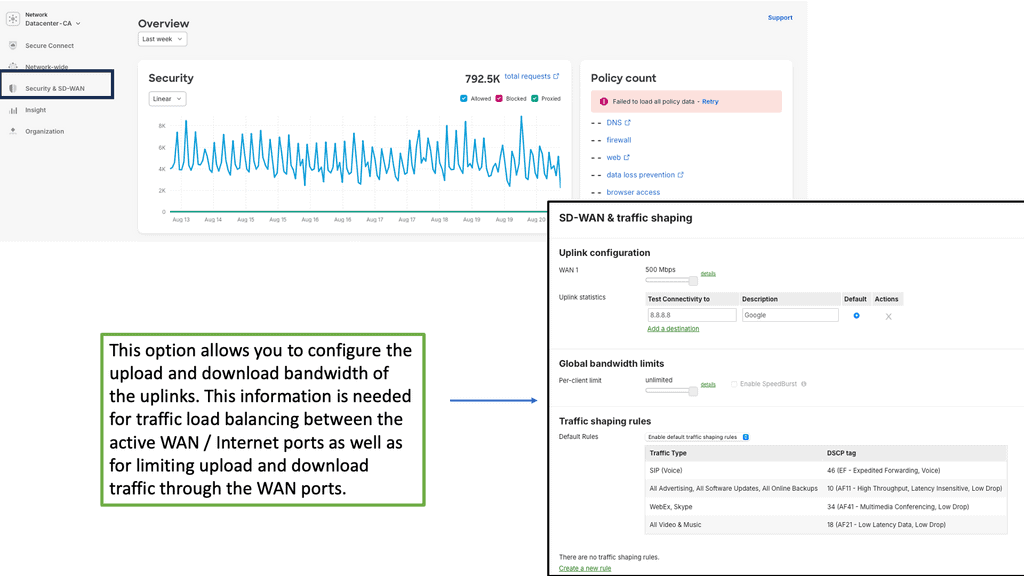
Example Product: Cisco Meraki

**Section 1: Simplified Network Management**

One of the standout features of the Cisco Meraki platform is its user-friendly interface. Gone are the days of complex configurations and cumbersome setups. With Meraki, IT administrators can manage their entire network from a single, intuitive dashboard. This centralized management capability allows for real-time monitoring, troubleshooting, and updates, all from the cloud. The simplicity of the platform means that even those with limited technical expertise can effectively manage and optimize their network.

**Section 2: Robust Security Features**

In today’s digital landscape, security is paramount. Cisco Meraki understands this and has built comprehensive security features into its platform. From advanced malware protection to intrusion prevention and content filtering, Meraki offers a multi-layered approach to cybersecurity. The platform also includes built-in security analytics, providing IT teams with valuable insights to proactively address potential threats. This level of security ensures that your network remains protected against both internal and external vulnerabilities.

**Section 3: Scalability and Flexibility**

Another significant advantage of the Cisco Meraki platform is its scalability. As your business grows, so too can your network. Meraki’s cloud-based nature allows for seamless integration of new devices and locations without the need for extensive hardware upgrades. This flexibility makes it an ideal solution for businesses of all sizes, from small startups to large multinational corporations. The platform’s ability to adapt to changing needs ensures that it can grow alongside your business.

**Section 4: Comprehensive Support and Training**

Cisco Meraki doesn’t just provide a platform; it offers a complete ecosystem of support and training. From comprehensive documentation and online tutorials to live webinars and a dedicated support team, Meraki ensures that you have all the resources you need to make the most of its platform. This commitment to customer success means that you’re never alone in your network management journey.

Challenges to Existing WAN

Traditional WAN architectures consist of private MPLS links complemented with Internet links as a backup. Standard templates in most Service Provider environments are usually broken down into Bronze, Silver, and Gold SLAs. 

However, these types of SLA do not fit all geographies and often should be fine-tuned per location. Capacity, reliability, analytics, and security are all central parts of the WAN that should be available on demand. Traditional infrastructure is very static, and bandwidth upgrades and service changes require considerable time processing and locking agility for new sites.

It’s not agile enough, and nothing can be performed on the fly to meet the growing business needs. In addition, the cost per bit for the private connection is high, which is problematic for bandwidth-intensive applications, especially when the upgrades are too costly and can’t be afforded. 

  • A distributed world of dissolving perimeters

Perimeters are dissolving, and the world is becoming distributed. Applications require a WAN to support distributed environments along with flexible network points. Centralized-only designs result in suboptimal traffic engineering and increased latency. Increased latency disrupts the application performance, and only a particular type of content can be put into a Content Delivery Network (CDN). CDN cannot be used for everything.

Traditional WANs are operationally complex; people likely perform different network and security functions. For example, you may have a DMVPN, Security, and Networking specialist. Some wear all hats, but they are few and far between. Different hats have different ideas, and agreeing on a minor network change could take ages.

  • The World of SD-WAN Static Network-Based

SD-WAN replaces traditional WAN routers that are agnostic to the underlying transport technology. You can use various link types, such as MPLS, LTE, and broadband. All combined. Based on policies generated by the business, SD-WAN enables load sharing across different WAN connections that more efficiently support today’s application environment.
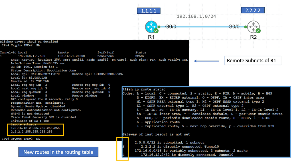
It pulls policy and intelligence out of the network and places them into an end-to-end solution orchestrated by a single pane of glass. SDN-WAN is not just about tunnels. It consists of components that work together to simplify network operations while meeting all bandwidth and resilience requirements.

Centralized network points are no longer adequate; we need network points positioned where they make the most sense for the application and user. Backhauling traffic to a central data center is illogical, and connecting remote sites to a SaaS or IaaS model over the public Internet is far more efficient. The majority of enterprises prefer to connect remote sites directly to cloud services. So why not let them do this in the best possible way?

A new style of WAN and SD-WAN

We require a new WAN style and a shift from a network-based approach to an application-based approach. The new WAN no longer looks solely at the network to forward packets. Instead, it looks at the business application and decides how to optimize it with the correct forwarding behavior. This new style of forwarding is problematic with traditional WAN architecture.

Making business logic decisions with IP and port number information is challenging. Standard routing is packet by packet and can only set part of the picture. They have routing tables and perform forwarding but essentially operate on their little island, losing out on a holistic view required for accurate end-to-end decision-making. An additional layer of information is needed.

A controller-based approach offers the necessary holistic view. We can now make decisions based on global information, not solely on a path-by-path basis. Getting all the routing information and compiling it into a dashboard to make a decision is much more efficient than making local decisions that only see parts of the network. 

From a customer’s viewpoint, what would the perfect WAN look like if you could roll back the clock and start again?   

Related: For additional pre-information, you may find the following helpful:

  1. Transport SDN
  2. SD WAN Diagram 
  3. Overlay Virtual Networking

SD WAN Overlay

Introducing the SD-WAN Overlay

SD-WAN decouples (separates) the WAN infrastructure, whether physical or virtual, from its control plane mechanism and allows applications or application groups to be placed into virtual WAN overlays. The separation will enable us to bring many enhancements and improvements to a WAN that has had little innovation in the past compared to the rest of the infrastructure, such as server and storage modules.

With server virtualization, several virtual machines create application isolation on a physical server. Applications placed in VMs operate in isolation, yet the VMs are installed on the same physical hosts.

Consider SD-WAN to operate with similar principles. Each application or group can operate independently when traversing the WAN to endpoints in the cloud or other remote sites. These applications are placed into a virtual SDWAN overlay.

Overlay Networking

Overlay networking is an approach to computer networking that involves building a layer of virtual networks on top of an existing physical network. This approach improves the underlying infrastructure’s scalability, performance, and security. It also allows for the creation of virtual networks that span multiple physical networks, allowing for greater flexibility in traffic routes.

**Virtualization**

At the core of overlay networking is the concept of virtualization. This involves separating the physical infrastructure from the virtual networks, allowing greater control over allocating resources. This separation also allows the creation of virtual network segments that span multiple physical networks. This provides an efficient way to route traffic and the ability to provide additional security and privacy measures.

**Underlay network**

A network underlay is a physical infrastructure that provides the foundation for a network overlay, a logical abstraction of the underlying physical network. The network underlay provides the physical transport of data between nodes, while the overlay provides logical connectivity.

The network underlay can comprise various technologies, such as Ethernet, Wi-Fi, cellular, satellite, and fiber optics. It is the foundation of a network overlay and essential for its proper functioning. It provides data transport and physical connections between nodes. It also provides the physical elements that make up the infrastructure, such as routers, switches, and firewalls.

Example: DMVPN over IPSec

Understanding DMVPN

DMVPN is a dynamic VPN technology that simplifies establishing secure connections between multiple sites. Unlike traditional VPNs, which require point-to-point tunnels, DMVPN uses a hub-and-spoke architecture, allowing any-to-any connectivity. This flexibility enables organizations to quickly scale their networks and accommodate dynamic changes in their infrastructure.

On the other hand, IPsec provides a robust framework for securing IP communications. It offers encryption, authentication, and integrity mechanisms, ensuring that data transmitted over the network remains confidential and protected against unauthorized access. IPsec is a widely adopted standard that is compatible with various network devices and software, making it an ideal choice for securing DMVPN connections.

The combination of DMVPN and IPsec brings numerous benefits to organizations. Firstly, DMVPN’s dynamic nature allows for easy scalability and improved network resiliency. New sites can be added seamlessly without the need for manual configuration changes. Additionally, DMVPN over IPsec provides strong encryption, ensuring the confidentiality of sensitive data. Moreover, DMVPN’s any-to-any connectivity optimizes network traffic flow, enhancing performance and reducing latency.


Overlay networking
Diagram: Overlay networking. Source Researchgate.

Key Challenges: Driving Overlay Networking & SD-WAN

**Challenge: We need more bandwidth**

Modern businesses demand more bandwidth than ever to connect their data, applications, and services. As a result, we have many things to consider with the WAN, such as regulations, security, visibility, branch, data center sites, remote workers, internet access, cloud, and traffic prioritization. They were driving the need for SD-WAN.

The concepts and design principles of creating a wide area network (WAN) to provide resilient and optimal transit between endpoints have continuously evolved. However, the driver behind building a better WAN is to support applications that demand performance and resiliency.

**Challenge: Suboptimal traffic flow**

The optimal route will be the fastest or most efficient and, therefore, preferred to transfer data. Sub-optimal routes will be slower and, hence, not the selected route. Centralized-only designs resulted in suboptimal traffic flow and increased latency, which will degrade application performance.

A key point to note is that traditional networks focus on centralized points in the network that all applications, network, and security services must adhere to. These network points are fixed and cannot be changed.

**Challenge: Network point intelligence**

However, the network should evolve to have network points positioned where it makes the most sense for the application and user, not based on a previously validated design for a different application era. For example, many branch sites do not have local Internet breakouts.

So, for this reason, we backhauled internet-bound traffic to secure, centralized internet portals at the H.Q. site. As a result, we sacrificed the performance of Internet and cloud applications. Designs that place the H.Q. site at the center of connectivity requirements inhibit the dynamic access requirements for digital business.

**Challenge: Hub and spoke drawbacks**

Simple spoke-type networks are sub-optimal because you always have to go to the center point of the hub and then out to the machine you need rather than being able to go directly to whichever node you need. As a result, the hub becomes a bottleneck in the network as all data must go through it. With a more scattered network using multiple hubs and switches, a less congested and more optimal route could be found between machines.

Cisco SD WAN Overlay
Diagram: Cisco SD-WAN overlay. Source Network Academy

The Fabric:

The word fabric comes from the fact that there are many paths to move from one server to another to ease balance and traffic distribution. SDN aims to centralize the order that enables the distribution of the flows over all the fabric paths. Then, we have an SDN controller device. The SDN controller can also control several fabrics simultaneously, managing intra and inter-datacenter flows.

SD-WAN is used to control and manage a company’s multiple WANs. There are different types of WAN: Internet, MPLS, LTE, DSL, fiber, wired network, circuit link, etc. SD-WAN uses SDN technology to control the entire environment. Like SDN, the data plane and control plane are separated. A centralized controller must be added to manage flows, routing or switch policies, packet priority, network policies, etc. SD-WAN technology is based on overlay, meaning nodes representing underlying networks.

Centralized logic:

In a traditional network, each device’s transport functions and controller layer are resident. This is why any configuration or change must be done box-by-box. Configuration was carried out manually or, at the most, an Ansible script. SD-WAN brings Software-Defined Networking (SDN) concepts to the enterprise branch WAN.

Software-defined networking (SDN) is an architecture, whereas SD-WAN is a technology that can be purchased and built on SDN’s foundational concepts. SD-WAN’s centralized logic stems from SDN. SDN separates the control from the data plane and uses a central controller to make intelligent decisions, similar to the design that most SD-WAN vendors operate.

A holistic view:

The controller and the SD-WAN overlay have a holistic view. The controller supports central policy management, enabling network-wide policy definitions and traffic visibility. The SD-WAN edge devices perform the data plane. The data plane is where simple forwarding occurs, and the control plane, which is separate from the data plane, sets up all the controls for the data plane to forward.

Like SDN, the SD-WAN overlay abstracts network hardware into a control plane with multiple data planes to make up one large WAN fabric. As the control layer is abstracted and decoupled above the physicals and running in software, services can be virtualized and delivered from a central location to any point on the network.

SD-WAN Overlay Features

SD-WAN Overlay Feature 1: Combining the transports:

At its core, SD-WAN shapes and steers application traffic across multiple WAN means of transport. Building on the concept of link bonding to combine numerous means of transport and transport types, the SD-WAN overlay improves the idea by moving the functionality up the stack—first, SD-WAN aggregates last-mile services, representing them as a single pipe to the application.SD-WAN allows you to combine all transport links into one big pipe. SD-WAN is transport agnostic. As it works by abstraction, it does not care what transport links you have. Maybe you have MPLS, private Internet, or LTE. It can combine all these or use them separately.

SD-WAN Overlay Feature 2: location:

From a central location, SD-WAN pulls all of these WAN resources together, creating one large WAN fabric that allows administrators to slice up the WAN to match the application requirements that sit on top. Different applications traverse the WAN, so we need the WAN to react differently. For example, if you’re running a call center, you want a low delay, latency, and high availability with Voice traffic. You may wish to use this traffic to use an excellent service-level agreement path.

SD WAN traffic steering
Diagram: SD-WAN traffic steering. Source Cisco.

SD-WAN Overlay Feature 3: steering:

Traffic steering may also be required: voice traffic to another path if, for example, the first Path is experiencing high latency. If it’s not possible to steer traffic automatically to a link that is better performing, run a series of path remediation techniques to try to improve performance. File transfer differs from real-time Voice: you can tolerate more delay but need more B/W. Here, you may want to use a combination of WAN transports ( such as customer broadband and LTE ) to achieve higher aggregate B/W.

This also allows you to automatically steer traffic over different WAN transports when there is a deflagration on one link. With the SD-WAN overlay, we must start thinking about paths, not links.

SD-WAN Overlay Feature 4: decisions:

At its core, SD-WAN enables real-time application traffic steering over any link, such as broadband, LTE, and MPLS, assigning pre-defined policies based on business intent. Steering policies support many application types, making intelligent decisions about how WAN links are utilized and which paths are taken.

The concept of an underlay and overlay are not new, and SD-WAN borrows these designs. First, the underlay is the physical or virtual world, such as the physical infrastructure. Then, we have the overlay, where all the intelligence can be set. The SDWAN overlay represents the virtual WANs that hold your different applications.

A virtual WAN overlay enables us to steer traffic and combine all bandwidths. Similar to how applications are mapped to V.M. in the server world, with SD-WAN, each application is mapped to its own virtual SD-WAN overlay. Each virtual SD-WAN overlay can have its own SD-WAN security policies, topologies, and performance requirements.

SD-WAN Overlay Feature 5:-Aware Routing Capabilities

Not only do we need application visibility to forward efficiently over either transport, but we also need the ability to examine deep inside the application and look at the sub-applications. For example, we can determine whether Facebook chat is over regular Facebook. This removes the application’s mystery and allows you to balance loads based on sub-applications. It’s like using a scalpel to configure the network instead of a sledgehammer.

SD-WAN Overlay Feature 6: Of Integration With Existing Infrastructure

The risk of introducing new technologies may come with a disruptive implementation strategy. Loss of service damages more than the engineer’s reputation. It hits all areas of the business. The ability to seamlessly insert new sites into existing designs is a vital criterion. With any network change, a critical evaluation is to know how to balance risk with innovation while still meeting objectives.

How aligned is marketing content to what’s happening in reality? It’s easy for marketing materials to implement their solution at Layer 2 or 3! It’s an entirely different ball game doing this. SD-WAN carries a certain amount of due diligence. One way to read between the noise is to examine who has real-life deployments with proven Proof of concept (POC) and validated designs. Proven POC will help you guide your transition in a step-by-step manner.

SD-WAN Overlay Feature 7: Specific Routing Topologies

Every company has different requirements for hub and spoke full mesh and Internet PoP topologies. For example, Voice should follow a full mesh design, while Data requires a hub and spokes connecting to a central data center. Nearest service availability is the key to improved performance, as there is little we can do about the latency Gods except by moving services closer together. 

SD-WAN Overlay Feature 8: Device Management & Policy Administration

The manual box-by-box approach to policy enforcement is not the way forward. It’s similar to stepping back into the Stone Age to request a catered flight. The ability to tie everything to a template and automate enables rapid branch deployments, security updates, and configuration changes. The optimal solutions have everything in one place and can dynamically push out upgrades.

SD-WAN Overlay Feature 9: Available With Automatic Failovers

You cannot apply a singular viewpoint to high availability. An end-to-end solution should address the high availability requirements of the device, link, and site level. WANs can fail quickly, but this requires additional telemetry information to detect failures and brownout events. 

SD-WAN Overlay Feature 10: On All Transports

Irrespective of link type, whether MPLS, LTE, or the Internet, we need the capacity to encrypt on all those paths without the excess baggage of IPsec. Encryption should happen automatically, and the complexity of IPsec should be abstracted.

**Application-Orientated WAN**

Push to the cloud:  

When geographically dispersed users connect back to central locations, their consumption triggers additional latency, degrading the application’s performance. No one can get away from latency unless we find ways to change the speed of light. One way is to shorten the link by moving to cloud-based applications.

The push to the cloud is inevitable. Most businesses are now moving away from on-premise in-house hosting to cloud-based management. Nevertheless, the benefits of moving to the cloud are manifold. It is easier for so many reasons.

The ready-made global footprint enables the usage of SaaS-based platforms that negate the drawbacks of dispersed users tromboning to a central data center. This software is pivotal to millions of businesses worldwide, which explains why companies such as Capsifi are so popular.

Logically positioned cloud platforms are closer to the mobile user. It’s increasingly far more efficient from the technical and business standpoint to host these applications in the cloud, which makes them available over the public Internet.

Bandwidth intensive applications:

Richer applications, multimedia traffic, and growth in the cloud application consumption model drive the need for additional bandwidth. Unfortunately, we can only fit so much into a single link. The congestion leads to packet drops, ultimately degrading application performance and user experience. In addition, most applications ride on TCP, yet TCP was not designed with performance.

Organic growth:

Organic business growth is a significant driver of additional bandwidth requirements. The challenge is that existing network infrastructures are static and unable to respond to this growth in a reasonable period adequately. The last mile of MPLS locks you in and kills agility. Circuit lead times impede the organization’s productivity and create an overall lag.

Costs:

A WAN virtualization solution should be simple. To serve the new era of applications, we need to increase the link capacity by buying more bandwidth. However, nothing is as easy as it may seem. The WAN is one of the network’s most expensive parts, and employing link oversubscription to reduce congestion is too costly.

Furthermore, bandwidth comes at a cost, and the existing TDM-based MPLS architectures cannot accommodate application demands. 

Traditional MPLS is feature-rich and offers many benefits. No one doubts this fact. MPLS will never die. However, it comes at a high cost for relatively low bandwidth. Unfortunately, MPLS’s price and capabilities are not a perfect couple.

Hybrid connectivity:

Since there is not one stamp for the entire world, similar applications will have different forwarding preferences. Therefore, application flows are dynamic and change depending on user consumption. Furthermore, the MPLS, LTE, and Internet links often complement each other since they support different application types.

For example, Storage and Big data replication traffic are forwarded through the MPLS links, while cheaper Internet connectivity is used for standard Web-based applications.

Limitations of protocols:

When left to its defaults, IPsec is challenged by hybrid connectivity. IPSec architecture is point-to-point, not site-to-site. As a result, it doesn’t natively support redundant uplinks. Complex configurations are required when sites have multiple uplinks to multiple providers.

By default, IPsec is not abstracted; one session cannot be used over multiple uplinks, causing additional issues with transport failover and path selection. It’s a Swiss Army knife of features, and much of IPSec’s complexities should be abstracted. Secure tunnels should be torn up and down immediately, and new sites should be incorporated into a secure overlay without much delay or manual intervention. 

Internet of Things (IoT):

Security and bandwidth consumption are key issues when introducing IP-enabled objects and IoT access technologies. IoT is all about Data and will bring a shed load of additional overheads for networks to consume. As millions of IoT devices come online, how efficiently do we segment traffic without complicating the network design further? Complex networks are hard to troubleshoot, and simplicity is the mother of all architectural success. Furthermore, much IoT processing requires communication to remote IoT platforms. How do we account for the increased signaling traffic over the WAN? The introduction of billions of IoT devices leaves many unanswered questions.

Branch NFV:

There has been strong interest in infrastructure consolidation by deploying Network Function Virtualization (NFV) at the branch. Enabling on-demand service and chaining application flows are key drivers for NFV. However, traditional service chaining is static since it is bound to a particular network topology. Moreover, it is typically built through manual configuration and is prone to human error.

 SD-WAN overlay path monitoring:

SD-WAN monitors the paths and the application performance on each link (Internet, MPLS, LTE ) and then chooses the best path based on real-time conditions and the business policy. In summary, the underlay network is the physical or virtual infrastructure above which the overlay network is built. An SDWAN overlay network is a virtual network built on top of an underlying Network infrastructure/Network layer (the underlay).

Controller-based policy:

An additional layer of information is needed to make more intelligent decisions about how and where to forward application traffic. SD-WAN offers a controller-based policy approach that incorporates a holistic view.

A central controller can now make decisions based on global information, not solely on a path-by-path basis with traditional routing protocols.  Getting all the routing information and compiling it into the controller to make a decision is much more efficient than making local decisions that only see a limited part of the network.

The SD-WAN Controller provides physical or virtual device management for all SD-WAN Edges associated with the controller. This includes, but is not limited to, configuration and activation, IP address management, and pushing down policies onto SD-WAN Edges located at the branch sites.

SD-WAN Overlay Case Study:

Personal Note: I recently consulted for a private enterprise. Like many enterprises, they have many applications, both legacy and new. No one knew about courses and applications running over the WAN; visibility was low. For the network design, the H.Q. has MPLS and Direct Internet access. Nothing is new here; this design has been in place for the last decade. All traffic is backhauled to the HQ/MPLS headend for security screening. The security stack, including firewalls, IDS/IPS, and anti-malware, was in the H.Q. The remote sites have high latency and limited connectivity options.

More importantly, they are transitioning their ERP system to the cloud. As apps move to the cloud, they want to avoid fixed WAN, a big driver for a flexible SD-WAN solution. They also have remote branches, which are hindered by high latency and poorly managed IT infrastructure. But they don’t want an I.T. representative at each site location. They have heard that SD-WAN has a centralized logic and can view the entire network from one central location. These remote sites must receive large files from the H.Q.; the branch sites’ transport links are only single-customer broadband links.

Some remote sites have LTE, and the bills are getting more significant. The company wants to reduce costs with dedicated Internet access or customer/business broadband. They have heard that you can combine different transports with SD-WAN and have several path remediations on degraded transports for better performance. So, they decided to roll out SD-WAN. From this new architecture, they gained several benefits.

SD-WAN Visibility

When your business-critical applications operate over different provider networks, troubleshooting and finding the root cause of problems becomes more challenging. So, visibility is critical to business. SD-WAN allows you to see network performance data in real-time and is essential for determining where packet loss, latency, and jitter are occurring so you can resolve the problem quickly.

You also need to be able to see who or what is consuming bandwidth so you can spot intermittent problems. For all these reasons, SD-WAN visibility needs to go beyond network performance metrics and provide greater insight into the delivery chains that run from applications to users.

  • Understand your baselines:

Visibility is needed to complete the network baseline before the SD-WAN is deployed. This enables the organization to understand existing capabilities, the norm, what applications are running, the number of sites connected, what service providers used, and whether they’re meeting their SLAs. Visibility is critical to obtaining a complete picture, so teams understand how to optimize the business infrastructure. SD-WAN gives you an intelligent edge, so you can see all the traffic and act on it immediately.

First, look at the visibility of the various flows, the links used, and any issues on those links. Then, if necessary, you can tweak the bonding policy to optimize the traffic flow. Before the rollout of SD-WAN, there was no visibility into the types of traffic, and different apps used what B.W. They had limited knowledge of WAN performance.

  • SD-WAN offers higher visibility:

With SD-WAN, they have the visibility to control and class traffic on layer seven values, such as what URL you are using and what Domain you are trying to hit, along with the standard port and protocol. All applications are not equal; some run better on different links. If an application is not performing correctly, you can route it to a different circuit. With the SD-WAN orchestrator, you have complete visibility across all locations, all links, and into the other traffic across all circuits. 

  • SD-WAN High Availability:

Any high-availability solution aims to ensure that all network services are resilient to failure. It aims to provide continuous access to network resources by addressing the potential causes of downtime through functionality, design, and best practices. The previous high-availability design was active and passive with manual failover. It was hard to maintain, and there was a lot of unused bandwidth. Now, they use resources more efficiently and are no longer tied to the bandwidth of the first circuit.

There is a better granular application failover mechanism. You can also select which apps are prioritized if a link fails or when a certain congestion ratio is hit. For example, you have LTE as a backup, which can be expensive. So applications marked high priority are steered over the backup link, but guest WIFI traffic isn’t.  

  • Flexible topology:

Before, they had a hub-and-spoke MPLS design for all applications. They wanted a complete mesh architecture for some applications, kept the existing hub, and spoke for others. However, the service provider couldn’t accommodate the level of granularity that they wanted.

With SD-WAN, they can choose topologies that are better suited to the application type. As a result, the network design is now more flexible and matches the application than the application matching a network design it doesn’t want.

Types of SD-WAN

The market for branch office wide-area network functionality is shifting from dedicated routing, security, and WAN optimization appliances to feature-rich SD-WAN. As a result, WAN edge infrastructure now incorporates a widening set of network functions, including secure routers, firewalls, SD-WAN, WAN path control, and WAN optimization, along with traditional routing functionality. Therefore, consider the following approach to deploying SD-WAN.

1. Application-based approach

With SD-WAN, we are shifting from a network-based approach to an application-based approach. The new WAN no longer looks solely at the network to forward packets. Instead, it looks at the business requirements and decides how to optimize the application with the correct forwarding behavior. This new way of forwarding would be problematic when using traditional WAN architectures.

Making business logic decisions with I.P. and port number information is challenging. Standard routing is the most common way to forward application traffic today, but it only assesses part of the picture when making its forwarding decision. 

These devices have routing tables to perform forwarding. Still, with this model, they operate and decide on their little island, losing the holistic view required for accurate end-to-end decision-making.  

2. SD-WAN: Holistic decision

The WAN must start making decisions holistically. It should not be viewed as a single module in the network design. Instead, it must incorporate several elements it has not integrated to capture the correct per-application forwarding behavior. The ideal WAN should be automatable to form a comprehensive end-to-end solution centrally orchestrated from a single pane of glass.

Managed and orchestrated centrally, this new WAN fabric is transport agnostic. It offers application-aware routing, regional-specific routing topologies, encryption on all transports regardless of link type, and high availability with automatic failover. All of these will be discussed shortly and are the essence of SD-WAN.  

3. SD-WAN and central logic        

Besides the virtual SD-WAN overlay, another key SD-WAN concept is centralized logic. Upon examining a standard router, local routing tables are computed from an algorithm to forward a packet to a given destination.

It receives routes from its peers or neighbors but computes paths locally and makes local routing decisions. The critical point to note is that everything is calculated locally. SD-WAN functions on a different paradigm.

Rather than using distributed logic, it utilizes centralized logic. This allows you to view the entire network holistically and with a distributed forwarding plane that makes real-time decisions based on better metrics than before.

This paradigm enables SD-WAN to see how the flows behave along the path. They are taking the fragmented control approach and centralizing it while benefiting from a distributed system. 

The SD-WAN controller, which acts as the brain, can set different applications to run over different paths based on business requirements and performance SLAs, not on a fixed topology. So, for example, if one path does not have acceptable packet loss and latency is high, we can move to another path dynamically.

4. Independent topologies

SD-WAN has different levels of networking and brings the concepts of SDN into the Wide Area Network. Similar to SDN, we have an underlay and an overlay network with SD-WAN. The WAN infrastructure, either physical or virtual, is the underlay, and the SDWAN overlay is in software on top of the underlay where the applications are mapped.

This decoupling or separation of functions allows different application or group overlays. Previously, the application had to work with a fixed and pre-built network infrastructure. With SD-WAN, the application can choose the type of topology it wants, such as a full mesh or hub and spoke. The topologies with SD-WAN are much more flexible.

5. The SD-WAN overlay

SD-WAN optimizes traffic over multiple available connections. It dynamically steers traffic to the best available link. Suppose the available links show any transmission issues. In that case, it will immediately transfer to a better path or apply remediation to a link if, for example, you only have a single link. SD-WAN delivers application flows from a source to a destination based on the configured policy and best available network path. A core concept of SD-WAN is overlaid.

SD-WAN solutions provide the software abstraction to create the SD-WAN overlay and decouple network software services from the underlying physical infrastructure. Multiple virtual overlays may be defined to abstract the underlying physical transport services, each supporting a different quality of service, preferred transport, and high availability characteristics.

6. Application mapping

Application mapping also allows you to steer traffic over different WAN transports. This steering is automatic and can be implemented when specific performance metrics are unmet. For example, if Internet transport has a 15% packet loss, the policy can be set to steer all or some of the application traffic over to better-performing MPLS transport.

Applications are mapped to different overlays based on business intent, not infrastructure details like IP addresses. When you think about overlays, it’s common to have, on average, four overlays. For example, you may have a gold, platinum, and bronze SDWAN overlay, and then you can map the applications to these overlays.

The applications will have different networking requirements, and overlays allow you to slice and dice your network if you have multiple application types. 

SD-WAN & WAN metrics

SD-WAN captures metrics that go far beyond the standard WAN measurements. For example, the traditional method measures packet loss, latency, and jitter metrics to determine path quality. These measurements are insufficient for routing protocols that only make the packet flow decision at layer 3 of the OSI model.

As we know, layer 3 of the OSI model lacks intelligence and misses the overall user experience. We must start looking at application transactions rather than relying on bits, bytes jitter, and latency.

SD-WAN incorporates better metrics beyond those a standard WAN edge router considers. These metrics may include application response time, network transfer, and service response time. Some SD-WAN solutions monitor each flow’s RTT, sliding windows, and ACK delays, not just the I.P. or TCP. This creates a more accurate view of the application’s performance.

Overlay Use Case: DMVPN Dual Cloud

Exploring Single Hub Dual Cloud Configuration

The Single Hub, Dual Cloud configuration, is a DMVPN setup in which a central hub site connects to two or more cloud service providers simultaneously. This configuration offers several advantages, such as increased redundancy, improved performance, and enhanced security.

By connecting to multiple cloud service providers, the Single Hub Dual Cloud configuration ensures redundancy if one provider experiences an outage. This redundancy enhances network availability and minimizes the risk of downtime, providing a robust and reliable network infrastructure.

With the Single Hub Dual Cloud configuration, network traffic can be load-balanced across multiple cloud service providers. This load balancing distributes the workload evenly, optimizing network performance and preventing bottlenecks. It allows for efficient utilization of network resources, resulting in enhanced user experience and improved application performance.

Summary: SD WAN Overlay

In today’s digital landscape, businesses increasingly rely on cloud-based applications, remote workforces, and data-driven operations. As a result, the demand for a more flexible, scalable, and secure network infrastructure has never been greater. This is where SD-WAN overlay comes into play, revolutionizing how organizations connect and operate.

SD-WAN overlay is a network architecture that allows organizations to abstract and virtualize their wide area networks, decoupling them from the underlying physical infrastructure. It utilizes software-defined networking (SDN) principles to create an overlay network that runs on top of the existing WAN infrastructure, enabling centralized management, control, and optimization of network traffic.

Key benefits of SD-WAN overlay 

1. Enhanced Performance and Reliability:

SD-WAN overlay leverages multiple network paths to distribute traffic intelligently, ensuring optimal performance and reliability. By dynamically routing traffic based on real-time conditions, businesses can overcome network congestion, reduce latency, and maximize application performance. This capability is particularly crucial for organizations with distributed branch offices or remote workers, as it enables seamless connectivity and productivity.

2. Cost Efficiency and Scalability:

Traditional WAN architectures can be expensive to implement and maintain, especially when organizations need to expand their network footprint. SD-WAN overlay offers a cost-effective alternative by utilizing existing infrastructure and incorporating affordable broadband connections. With centralized management and simplified configuration, scaling the network becomes a breeze, allowing businesses to adapt quickly to changing demands without breaking the bank.

3. Improved Security and Compliance:

In an era of increasing cybersecurity threats, protecting sensitive data and ensuring regulatory compliance are paramount. SD-WAN overlay incorporates advanced security features to safeguard network traffic, including encryption, authentication, and threat detection. Businesses can effectively mitigate risks, maintain data integrity, and comply with industry regulations by segmenting network traffic and applying granular security policies.

4. Streamlined Network Management:

Managing a complex network infrastructure can be a daunting task. SD-WAN overlay simplifies network management with centralized control and visibility, enabling administrators to monitor and manage the entire network from a single pane of glass. This level of control allows for faster troubleshooting, policy enforcement, and network optimization, resulting in improved operational efficiency and reduced downtime.

5. Agility and Flexibility:

In today’s fast-paced business environment, agility is critical to staying competitive. SD-WAN overlay empowers organizations to adapt rapidly to changing business needs by providing the flexibility to integrate new technologies and services seamlessly. Whether adding new branch locations, integrating cloud applications, or adopting emerging technologies like IoT, SD-WAN overlay offers businesses the agility to stay ahead of the curve.

Implementation of SD-WAN Overlay:

Implementing SD-WAN overlay requires careful planning and consideration. The following steps outline a typical implementation process:

1. Assess Network Requirements: Evaluate existing network infrastructure, bandwidth requirements, and application performance needs to determine the most suitable SD-WAN overlay solution.

2. Design and Architecture: Create a network design incorporating SD-WAN overlay while considering factors such as branch office connectivity, data center integration, and security requirements.

3. Vendor Selection: Choose a reliable and reputable SD-WAN overlay vendor based on their technology, features, support, and scalability.

4. Deployment and Configuration: Install the required hardware or virtual appliances and configure the SD-WAN overlay solution according to the network design. This includes setting up policies, traffic routing, and security parameters.

5. Testing and Optimization: Thoroughly test the SD-WAN overlay solution, ensuring its compatibility with existing applications and network infrastructure. Optimize the solution based on performance metrics and user feedback.

Conclusion: SD-WAN overlay is a game-changer for businesses seeking to optimize their network infrastructure. By enhancing performance, reducing costs, improving security, streamlining management, and enabling agility, SD-WAN overlay unlocks the true potential of connectivity. Embracing this technology allows organizations to embrace digital transformation, drive innovation, and gain a competitive edge in the digital era. In an ever-evolving business landscape, SD-WAN overlay is the key to unlocking new growth opportunities and future-proofing your network infrastructure.

Cyber security threat. Computer screen with programming code. Internet and network security. Stealing private information. Using technology to steal password and private data. Cyber attack crime

Software defined perimeter (SDP) A disruptive technology

Software-Defined Perimeter

In the evolving landscape of cybersecurity, organizations are constantly seeking innovative solutions to protect their sensitive data and networks from potential threats. One such solution that has gained significant attention is the Software Defined Perimeter (SDP). In this blog post, we will delve into the concept of SDP, its benefits, and how it is reshaping the future of network security.

The concept of SDP revolves around the principle of zero trust architecture. Unlike traditional network security models that rely on perimeter-based defenses, SDP adopts a more dynamic approach by providing secure access to users and devices based on their identity and context. By creating individualized and isolated connections, SDP reduces the attack surface and minimizes the risk of unauthorized access.

1. Identity-Based Authentication: SDP leverages strong authentication mechanisms such as multi-factor authentication (MFA) and certificate-based authentication to verify the identity of users and devices.

2. Dynamic Access Control: SDP employs contextual information such as user location, device health, and behavior analysis to dynamically enforce access policies. This ensures that only authorized entities can access specific resources.

3. Micro-Segmentation: SDP enables micro-segmentation, dividing the network into smaller, isolated segments. This ensures that even if one segment is compromised, the attacker's lateral movement is restricted.

1. Enhanced Security: SDP significantly reduces the risk of unauthorized access and lateral movement, making it challenging for attackers to exploit vulnerabilities.

2. Improved User Experience: SDP enables seamless and secure access to resources, regardless of user location or device type. This enhances productivity and simplifies the user experience.

3. Scalability and Flexibility: SDP can easily adapt to changing business requirements and scale to accommodate growing networks. It offers greater agility compared to traditional security models.

As organizations face increasingly sophisticated cyber threats, the need for advanced network security solutions becomes paramount. Software Defined Perimeter (SDP) presents a paradigm shift in the way we approach network security, moving away from traditional perimeter-based defenses towards a dynamic and identity-centric model. By embracing SDP, organizations can fortify their network security posture, mitigate risks, and ensure secure access to critical resources.

Highlights: Software-Defined Perimeter

Understanding Software-Defined Perimeter

1- ) The software-defined perimeter, also known as Zero-Trust Network Access (ZTNA), is a security framework that adopts a dynamic, identity-centric approach to protecting critical resources. Unlike traditional perimeter-based security measures, SDP focuses on authenticating and authorizing users and devices before granting access to specific resources. By providing granular control and visibility, SDP ensures that only trusted entities can establish a secure connection, significantly reducing the attack surface.

2- )  its core, a Software-Defined Perimeter leverages a zero-trust security model, meaning that trust is never assumed simply based on network location. Instead, SDP dynamically creates secure, encrypted connections to applications or data, only after users and devices are authenticated. This approach significantly reduces the attack surface by ensuring that unauthorized entities cannot even see the network resources, let alone access them.

3- ) an SDP can transform the way organizations approach security. One major advantage is the enhanced security posture, as SDPs effectively cloak network resources from potential attackers. Moreover, SDPs are highly scalable, allowing organizations to quickly adapt to changing demands without compromising security. This flexibility is particularly beneficial for businesses with remote workforces, as it facilitates secure access to resources from any location.

Key SDP Components:

To implement an effective SDP, several key components work in tandem to create a robust security architecture. These components include:

1. Identity-Based Authentication: SDP leverages strong identity verification techniques such as multi-factor authentication (MFA) and certificate-based authentication to ensure that only authorized users gain access.

2. Dynamic Provisioning: SDP enables dynamic policy-based provisioning, allowing organizations to adapt access controls based on real-time context and user attributes.

3. Micro-Segmentation: With SDP, organizations can establish micro-segments within their network, isolating critical resources from potential threats and limiting lateral movement.

Example Micro-segmentation Technology:

Network Endpoint Groups (NEGs)

Network Endpoint Groups, or NEGs, are collections of IP address-port pairs that enable you to define how traffic is distributed across your applications. This flexibility makes NEGs a versatile tool, particularly in scenarios involving microsegmentation. Microsegmentation involves dividing a network into smaller, isolated segments to improve security and traffic management. NEGs support both zonal and serverless applications, allowing you to efficiently manage your infrastructure’s traffic flow.


The Role of NEGs in Microsegmentation

One of the standout features of NEGs is their ability to support microsegmentation within Google Cloud. By using NEGs, you can create precise policies that govern the flow of data between different segments of your network. This granular control is vital for security, as it allows you to isolate sensitive data and applications, minimizing the risk of unauthorized access. With NEGs, you can ensure that each microservice in your architecture communicates only with the necessary components, further enhancing your network’s security posture.


network endpoint groups

**A Disruptive Technology**

Over the last few years, there has been tremendous growth in the adoption of software-defined perimeter solutions and zero-trust network design. This has resulted in SDP VPN becoming a disruptive technology, especially when replacing or working with the existing virtual private network. Why? because the steps that software-defined perimeter proposes are needed.

Challenge With today’s Security

Today’s network security architectures, tools, and platforms are lacking in many ways when trying to combat current security threats. From a bird’ s-eye view, the zero-trust software-defined perimeter (SDP) stages are relatively simple. SDP requires that endpoints, both internal and external to an organization, authenticate and then be authorized before being granted network access. Once these steps occur, two-way encrypted connections between the requesting entity and the intended protected resource are created.

Example SDP Technology: VPC Service Controls

**What Are VPC Service Controls?**

VPC Service Controls are a security feature in Google Cloud that help define a secure perimeter around Google Cloud resources. By creating service perimeters, organizations can restrict data exfiltration and mitigate risks associated with unauthorized access to sensitive resources. This feature is particularly useful for businesses that need to comply with strict regulatory requirements, as it provides a framework for managing and protecting data more effectively.

**Key Features and Benefits**

One of the standout features of VPC Service Controls is the ability to set up service perimeters, which act as virtual borders around cloud services. These perimeters help prevent data from being accessed by unauthorized users, both inside and outside the organization. Additionally, VPC Service Controls offer context-aware access, allowing organizations to define access policies based on factors such as user location, device security status, and time of access. This granular control ensures that only authorized users can interact with sensitive data.

VPC Security Controls VPC Service Controls

**Implementing VPC Service Controls in Your Organization**

To effectively implement VPC Service Controls, organizations should begin by identifying the resources that require protection. This involves assessing which data and services are most critical to the business and determining the appropriate level of security needed. Once these resources are identified, service perimeters can be configured using the Google Cloud Console. It’s important to regularly review and adjust these configurations to adapt to changing security requirements and business needs.

**Best Practices for Maximizing Security**

To maximize the security benefits of VPC Service Controls, organizations should follow several best practices. First, regularly audit and monitor access logs to detect any unauthorized attempts to access protected resources. Second, integrate VPC Service Controls with other Google Cloud security features, such as Identity and Access Management (IAM) and Cloud Audit Logs, to create a comprehensive security strategy. Finally, ensure that all employees are trained on security protocols and understand the importance of maintaining data integrity.

Benefits of Software-Defined Perimeter:

1. Enhanced Security: SDP employs a zero-trust approach, ensuring that only authorized users and devices can access the network. This eliminates the risk of unauthorized access and reduces the attack surface.

2. Scalability: SDP allows organizations to scale their networks without compromising security. It seamlessly accommodates new users, devices, and applications, making it ideal for expanding businesses.

3. Simplified Management: With SDP, managing access controls becomes more straightforward. IT administrators can easily assign and revoke permissions, reducing the administrative burden.

4. Improved Performance: By eliminating the need for backhauling traffic through a central gateway, SDP reduces latency and improves network performance, enhancing the overall user experience.

Implementing Software-Defined Perimeter:

**Deploying SDP in Your Organization**

Implementing SDP requires a strategic approach to ensure a seamless transition. Begin by identifying the critical assets that need protection and mapping out access requirements for different user groups.

Next, choose an SDP solution that aligns with your organization’s needs and integrate it with existing infrastructure. It’s crucial to provide training for your IT team to effectively manage and maintain the system.

Additionally, regularly monitor and update the SDP framework to adapt to evolving security threats and organizational changes.

Implementing SDP requires a systematic approach and careful consideration of various factors. Here are the critical steps involved in deploying SDP:

1. Identify Critical Assets: Determine the applications and resources that require enhanced security measures. This could include sensitive data, intellectual property, or customer information.

2. Define Access Policies: Establish granular access policies based on user roles, device types, and locations. This ensures that only authorized individuals can access specific resources.

3. Implement Authentication Mechanisms: To verify user identities, incorporate strong authentication measures such as multi-factor authentication (MFA) or biometric authentication.

4. Implement Encryption: Encrypt all data in transit to prevent eavesdropping or unauthorized interception.

5. Continuous Monitoring: Regularly monitor network activity and analyze logs to identify suspicious behavior or anomalies.

For pre-information, you may find the following post helpful:

  1. SDP Network
  2. Software Defined Internet Exchange
  3. SDP VPN

Software-Defined Perimeter

A software-defined perimeter constructs a virtual boundary around company assets. This separates it from access-based controls, restricting user privileges but allowing broad network access. The three fundamental pillars on which a software-defined perimeter is built are Zero Trust:

It leverages micro-segmentation to apply the principle of least privilege to the network, ultimately reducing the attack surface. Identity-centric: It’s designed around the user identity and additional contextual parameters, not the IP address.

The Software-Defined Perimeter Proposition

Security policy flexibility is offered with fine-grained access control that dynamically creates and removes inbound and outbound access rules. Therefore, a software-defined perimeter minimizes the attack surface for bad actors to play with—a small attack surface results in a small blast radius. So less damage can occur.

A VLAN has a relatively large attack surface, mainly because the VLAN contains different services. SDP eliminates the broad network access that VLANs exhibit. SDP has a separate data and control plane.

A control plane sets up the controls necessary for data to pass from one endpoint to another. Separating the control from the data plane renders protected assets “black,” thereby blocking network-based attacks. You cannot attack what you cannot see.

Example: VLAN-based Segmentation

**Challenges and Considerations**

While VLAN-based segmentation offers many advantages, it also presents challenges that need addressing:

1. **Complexity in Management**: With increased segmentation, the complexity of managing and troubleshooting the network can rise. Proper training and tools are essential.

2. **Compatibility Issues**: Ensure that all network devices support VLANs and are configured correctly to avoid communication breakdowns.

3. **Security Oversight**: While VLANs enhance security, they are not foolproof. Regular audits and updates are necessary to maintain a robust security posture.

Spanning Tree Root Switch stp port states


The IP Address Is Not a Valid Hook

We should know that IP addresses are lost in today’s hybrid environment. SDP provides a connection-based security architecture instead of an IP-based one. This allows for many things. For one, security policies follow the user regardless of location. Let’s say you are doing forensics on an event 12 months ago for a specific IP.

However, that IP address is a component in a test DevOps environment. Do you care? Anything tied to IP is ridiculous, as we don’t have the right hook to hang things on for security policy enforcement.

Example – Firewalling based on Tags & Labels

Firewall tags

Software-defined perimeter; Identity-driven access

Identity-driven network access control is more precise in measuring the actual security posture of the endpoint. Access policies tied to IP addresses cannot offer identity-focused security. SDP enables the control of all connections based on pre-vetting who can connect and to what services.

If you do not meet this level of trust, you can’t, for example, access the database server, but you can access public-facing documents. Users are granted access only to authorized assets, preventing lateral movements that will probably go unnoticed when traditional security mechanisms are in place.

Example Technology: IAP in Google Cloud

### How IAP Works

IAP functions by intercepting user requests before they reach the application. It verifies the user’s identity and context, allowing access only if the user’s credentials match the predefined security policies. This process involves authentication through Google Identity Platform, which leverages OAuth 2.0, OpenID Connect, and other standards to confirm user identity efficiently. Once authenticated, IAP evaluates the context, such as the user’s location or device, to further refine access permissions.

### Benefits of Using IAP on Google Cloud

Implementing IAP on Google Cloud offers several compelling benefits. First, it enhances security by centralizing access control, reducing the risk of unauthorized entry. Additionally, IAP simplifies the user experience by eliminating the need for multiple login credentials across different applications. It also supports granular access control, allowing organizations to tailor permissions based on user roles and contexts, thereby improving operational efficiency.

### Setting Up IAP on Google Cloud

Setting up IAP on Google Cloud is a straightforward process. Administrators begin by enabling IAP in the Google Cloud Console. Once activated, they can configure access policies, determining who can access which resources and under what conditions. The system’s flexibility allows administrators to integrate IAP with various identity providers, ensuring compatibility with existing authentication frameworks. Comprehensive documentation and support from Google Cloud further streamline the setup process.

Identity aware proxy

Information & Infrastructure Hiding 

SDP does a great job of hiding information and infrastructure. The SDP architectural components ( the SDP controller and gateways ) are “dark, ” providing resilience against high- and low-volume DDoS attacks. A low-bandwidth DDoS attack may often bypass traditional DDoS security controls. However, the SDP components do not respond to connections until the requesting clients are authenticated and authorized, allowing only good packets through.

A suitable security protocol for this is single packet authorization (SPA). Single Packet Authorization, or Authentication, gives the SDP components a default “deny-all” security posture.

The “default deny” can be achieved because if an accepting host receives any packet other than a valid SPA packet, it assumes it is malicious. The packet will get dropped, and a notification will not get sent back to the requesting host. This stops the survey at the door, silently detecting and dropping bad packets.

What is Port Knocking?

Port knocking is a security technique that involves sequentially probing a predefined sequence of closed ports on a network to establish a connection with a desired service. It acts as a virtual secret handshake, allowing users to access specific services or ports that would otherwise remain hidden or blocked from unauthorized access.

Port knocking typically involves sending connection attempts to a series of ports in a specific order, which serves as a secret code. Once a listening daemon or firewall detects the correct sequence, it dynamically opens the desired port and allows the connection. This stealthy approach helps to prevent unauthorized access and adds an extra layer of security to network services.

Sniffing a SPA packet

However, SPA can be subject to Man-In-The-Middle (MITM) attacks. If a bad actor can sniff an SPA packet, they can establish the TCP connection to the controller or AH client. However, there is another level of defense: the bad actor cannot complete the mutually encrypted connection (mTLS) without the client’s certificate.

SDP brings in the concept of mutually encrypted connections, also known as two-way encryption. The usual configuration for TLS is that the client authenticates the server, but TLS ensures that both parties are authenticated. Only validated devices and users can become authorized members of the SDP architecture.

We should also remember that the SPA is not a security feature that can be implemented to protect all. It has its benefits but does not take over from existing security technologies. SPA should work alongside them. The main reason for its introduction to the SDP world is to overcome the problems with TCP. TCP connects and then authenticates. With SPA, you authenticate first and then connect only then.


SPA Use Case
Diagram: SPA Use Case. Source mrash Github.

**The World of TCP & SDP**

When clients want to access an application with TCP, they must first set up a connection. There needs to be direct connectivity between the client and the application. So, this requires the application to be reachable and is carried out with IP addresses on each end. Then, once the connect stage is done, there is an authentication phase.

Once the authentication stage is completed, we can pass data. Therefore, we must connect, authenticate, and pass data through a stage. SDP reverses this.

The center of the software-defined perimeter is trust.

In Software-Defined Perimeter, we must establish trust between the client and the application before the client can set up the connection. The trust is bi-directional between the client and the SDP service and the application to the SDP service. Once trust has been established, we move into the next stage, authentication.

Once this has been established, we can connect the user to the application. This flips the entire security model and makes it more robust. The user has no idea of where the applications are located. The protected assets are hidden behind the SDP service, which in most cases is the SDP gateway, or some call this a connector.

Cloud Security Alliance (CSA) SDP

    • With the Cloud Security Alliance SDP architecture, we have several components:

Firstly, the IH & AH are the clients initiating hosts (IH) and the service accepting hosts (AH). The IH devices can be any endpoint device that can run the SDP software, including user-facing laptops and smartphones. Many SDP vendors have remote browser isolation-based solutions without SDP client software. The IH, as you might expect, initiates the connections.

With an SDP browser-based solution, the user accesses the applications using a web browser and only works with applications that can speak across a browser. So, it doesn’t give you the full range of TCP and UDP ports, but you can do many things that speak natively across HTML5.

Most browser-based solutions don’t require additional security posture checks to assess the end-user device rather than an endpoint with the client installed.

Software-Defined Perimeter: Browser-based solution

The AHs accept connections from the IHS and provide a set of services protected securely by the SDP service. They are under the administrative control of the enterprise domain. They do not acknowledge communication from any other host and will not respond to non-provisioned requests. This architecture enables the control plane to remain separate from the data plane, achieving a scalable security system.

The IH and AH devices connect to an SDP controller that secures access to isolated assets by ensuring that the users and their devices are authenticated and authorized before granting network access. After authenticating an IH, the SDP controller determines the list of AHs to which the IH is authorized to communicate. The AHs are then sent a list of IHs that should accept connections.

Aside from the hosts and the controller, we have the SDP gateway component, which provides authorized users and devices access to protected processes and services. The protected assets are located behind the gateway and can be architecturally positioned in multiple locations, such as the cloud or on-premise. The gateways can exist in various locations simultaneously.

**Highlighting Dynamic Tunnelling**

A user with multiple tunnels to multiple gateways is expected in the real world. It’s not a static path or a one-to-one relationship but a user-to-application relationship. The applications can exist everywhere, and the tunnel is dynamic and ephemeral.

For a client to connect to the gateway, latency or SYN SYN/ACK RTT testing should be performed to determine the Internet links’ performance. This ensures that the application access path always uses the best gateway, improving application performance.

Remember that the gateway only connects outbound on TCP port 443 (mTLS), and as it acts on behalf of the internal applications, it needs access to the internal apps. As a result, depending on where you position the gateway, either internal to the LAN, private virtual private cloud (VPC), or in the DMZ protected by local firewalls, ports may need to be opened on the existing firewall.

**Future of Software-Defined Perimeter**

As the digital landscape evolves, secure network access becomes even more crucial. The future of SDP looks promising, with advancements in technologies like Artificial Intelligence and Machine Learning enabling more intelligent threat detection and mitigation.

In an era where data breaches are a constant threat, organizations must stay ahead of cybercriminals by adopting advanced security measures. Software Defined Perimeter offers a robust, scalable, and dynamic security framework that ensures secure access to critical resources.

By embracing SDP, organizations can significantly reduce their attack surface, enhance network performance, and protect sensitive data from unauthorized access. The time to leverage the power of Software Defined Perimeter is now.

Closing Points on SDP

At its core, a Software Defined Perimeter is a security framework designed to protect networked applications by concealing them from external users. Unlike traditional security measures that rely on a perimeter-based approach, SDP focuses on identity-based access controls. This means that users must be authenticated and authorized before they can even see the resources they’re trying to access. By effectively creating a “black cloud,” SDP ensures that only legitimate users can interact with the network, significantly reducing the risk of unauthorized access.

The operation of an SDP is based on a simple yet powerful principle: “Verify first, connect later.” It employs a multi-step process that involves:

1. **User Authentication**: Before any connection is established, SDP verifies the identity of the user or device attempting to connect.

2. **Access Validation**: Once authenticated, the system checks the user’s permissions and determines whether access should be granted.

3. **Dynamic Environment**: SDP dynamically provisions network connections, ensuring that only the necessary resources are exposed to the user.

This approach not only minimizes the attack surface but also adapts to the changing needs of the network, providing a flexible and scalable security solution.

The implementation of a Software Defined Perimeter offers numerous benefits:

– **Enhanced Security**: By hiding network resources and requiring stringent authentication, SDP provides a robust defense against cyber threats.

– **Reduced Attack Surface**: SDP ensures that only authorized individuals have access to specific resources, significantly reducing potential vulnerabilities.

– **Scalability and Flexibility**: As organizations grow, SDP can easily scale to meet their expanding security needs without requiring substantial changes to the existing infrastructure.

– **Improved User Experience**: With its streamlined access process, SDP can improve the overall user experience by reducing the friction often associated with security measures.

Summary: Software-Defined Perimeter

In today’s interconnected world, secure and flexible network solutions are paramount. Traditional perimeter-based security models can no longer protect sensitive data from sophisticated cyber threats. This is where the Software Defined Perimeter (SDP) comes into play, revolutionizing how we approach network security.

Understanding the Software-Defined Perimeter

The concept of the Software Defined Perimeter might seem complex at first. Still, it is a security framework that focuses on dynamically creating secure network connections as needed. Unlike traditional network architectures, where a fixed perimeter is established, SDP allows for granular access controls and encryption at the application level, ensuring that only authorized users can access specific resources.

Key Benefits of Implementing an SDP Solution

Implementing a Software-Defined Perimeter offers numerous advantages for organizations seeking robust and adaptive security measures. First, it provides a proactive defense against unauthorized access, as resources are effectively hidden from view until authorized users are authenticated. Additionally, SDP solutions enable organizations to enforce fine-grained access controls, reducing the risk of internal breaches and data exfiltration. Moreover, SDP simplifies the management of access policies, allowing for centralized control and greater visibility into network traffic.

Overcoming Network Limitations with SDP

Traditional network architectures often struggle to accommodate the demands of modern business operations, especially in scenarios involving remote work, cloud-based applications, and third-party partnerships. SDP addresses these challenges by providing secure access to resources regardless of their location or the user’s device. This flexibility ensures employees can work efficiently from anywhere while safeguarding sensitive data from potential threats.

Implementing an SDP Solution: Best Practices

When implementing an SDP solution, certain best practices should be followed to ensure a successful deployment. Firstly, organizations should thoroughly assess their existing network infrastructure and identify the critical assets that require protection. Next, selecting a reliable SDP solution provider that aligns with the organization’s specific needs and industry requirements is essential. Lastly, a phased approach to implementation can help mitigate risks and ensure a smooth transition for both users and IT teams.

Conclusion:

The Software Defined Perimeter represents a paradigm shift in network security, offering organizations a dynamic and scalable solution to protect their valuable assets. By adopting an SDP approach, businesses can achieve a robust security posture, enable seamless remote access, and adapt to the evolving threat landscape. Embracing the power of the Software Defined Perimeter is a proactive step toward safeguarding sensitive data and ensuring a resilient network infrastructure.

Cyber security threat. Young woman using computer and coding. Internet and network security. Stealing private information. Person using technology to steal password and private data. Cyber attack crime

SDP Network

SDP Network

The world of networking has undergone a significant transformation with the advent of Software-Defined Perimeter (SDP) networks. These innovative networks have revolutionized connectivity by providing enhanced security, flexibility, and scalability. In this blog post, we will explore the key features and benefits of SDP networks, their impact on traditional networking models, and the future potential they hold.

SDP networks, also known as "Black Clouds," are a paradigm shift in how we approach network security. Unlike traditional networks that rely on perimeter-based security, SDP networks adopt a "Zero Trust" model. This means that every user and device is treated as untrusted until verified, reducing the attack surface and enhancing security.


Another benefit of SDP networks is their flexibility. These networks are not tied to physical locations, allowing users to securely connect from anywhere in the world. This is especially beneficial for remote workers, as it enables them to access critical resources without compromising security.

SDP networks challenge the traditional hub-and-spoke networking model by introducing a decentralized approach. Instead of relying on a central point of entry, SDP networks establish direct connections between users and resources. This reduces latency, improves performance, and enhances the overall user experience.

As technology continues to evolve, the future of SDP networks looks promising. The rise of Internet of Things (IoT) devices and the increasing reliance on cloud-based services necessitate a more secure and scalable networking solution. SDP networks offer precisely that, with their ability to adapt to changing network demands and provide robust security measures.

In conclusion, SDP networks have emerged as a game-changer in the world of connectivity. By focusing on security, flexibility, and scalability, they address the limitations of traditional networking models. As organizations strive to protect their valuable data and adapt to evolving technological landscapes, SDP networks offer a reliable and future-proof solution.

Highlights: SDP Network

**The Core Principles of SDP Networks**

At the heart of an SDP network are three core principles: identity-based access, dynamic provisioning, and the principle of least privilege. Identity-based access ensures that only authenticated users can access the network, a significant shift from traditional models that rely on IP addresses. Dynamic provisioning allows the network to adapt in real-time, creating secure connections only when necessary, thus reducing the attack surface. Lastly, the principle of least privilege ensures that users receive only the access necessary to perform their tasks, minimizing potential security risks.

**How SDP Networks Work**

SDP networks function by utilizing a multi-stage process to verify user identity and device health before granting access. The process begins with an initial trust assessment where users are authenticated through a secure channel. Once authenticated, the user’s device undergoes a health check to ensure it meets security requirements. Following this, access is granted on a need-to-know basis, with micro-segmentation techniques used to isolate resources and prevent lateral movement within the network. This layered approach significantly enhances network security by ensuring that only verified users gain access to the resources they need.

Black Clouds – SDP

SDP networks, also known as ” Black Clouds,” represent a paradigm shift in network security. Unlike traditional perimeter-based security models, SDP networks focus on dynamically creating individualized perimeters around each user, device, or application. By adopting a Zero-Trust approach, SDP networks ensure that only authorized entities can access resources, reducing the attack surface and enhancing overall security.

SDP networks are a paradigm shift in network security. Unlike traditional perimeter-based approaches, SDP networks adopt a zero-trust model, where every user and device must be authenticated and authorized before accessing resources. This eliminates the vulnerabilities of a static perimeter and ensures secure access from anywhere.

Benefits of Software-Defined Perimeter:

1. Enhanced Security: SDP provides an additional layer of security by ensuring that only authenticated and authorized users can access the network. By implementing granular access controls, SDP reduces the attack surface and minimizes the risk of unauthorized access, making it significantly harder for cybercriminals to breach the system.

2. Improved Flexibility: Traditional network architectures often struggle to accommodate the increasing number of devices and the demand for remote access. SDP enables businesses to scale their network infrastructure effortlessly, allowing seamless connectivity for employees, partners, and customers, regardless of location. This flexibility is precious in today’s remote work environment.

3. Simplified Network Management: SDP simplifies network management by centralizing access control policies. This centralized approach reduces complexity and streamlines granting and revoking access privileges. Additionally, SDP eliminates the need for VPNs and complex firewall rules, making network management more efficient and cost-effective.

4. Mitigated DDoS Attacks: Distributed Denial of Service (DDoS) attacks can cripple an organization’s network infrastructure, leading to significant downtime and financial losses. SDP mitigates the impact of DDoS attacks by dynamically rerouting traffic and preventing the attack from overwhelming the network. This proactive defense mechanism ensures that network resources remain available and accessible to legitimate users.

5. Compliance and Regulatory Requirements: Many industries are bound by strict regulatory requirements, such as healthcare (HIPAA) or finance (PCI-DSS). SDP helps organizations meet these requirements by providing a secure framework that ensures data privacy and protection. Implementing SDP can significantly simplify the compliance process and reduce the risk of non-compliance penalties.

Example: Understanding Port Knocking

Port knocking is a technique in which a sequence of connection attempts is made to specific ports on a remote system. In a predetermined order, these attempts serve as a secret “knock” that triggers the opening of a closed port. Port knocking acts as a virtual doorbell, allowing authorized users to access a system that would otherwise remain invisible and protected from potential threats.

The Process: Port Knocking

To delve deeper, let’s explore how port knocking works. When a connection attempt is made to a closed port, the firewall silently drops it, leaving no trace of the effort. However, when the correct sequence of connection attempts is made, the firewall recognizes the pattern and dynamically opens the desired port, granting access to the authorized user. This sequence can consist of connections to multiple ports, further enhancing the system’s security.

**Understand your flows**

Network flows are time-bound communications between two systems. A single flow can be directly mapped to an entire conversation using a bidirectional transport protocol, such as TCP. However, a single flow for unidirectional transport protocols (e.g., UDP) might capture only half of a network conversation. Without a deep understanding of the application data, an observer on the network may not associate two UDP flows logically.

A system must capture all flow activity in an existing production network to move to a zero-trust model. The new security model should consider logging flows in a network over a long period to discover what network connections exist. Moving to a zero-trust model without this up-front information gathering will lead to frequent network communication issues, making the project appear invasive and disruptive.

Example: VPC Flow Logs

### What are VPC Flow Logs?

VPC Flow Logs are a feature in Google Cloud that captures information about the IP traffic going to and from network interfaces in your VPC. These logs offer detailed insights into network activity, helping you to identify potential security risks, troubleshoot network issues, and analyze the impact of network traffic on your applications.

### How VPC Flow Logs Work

When you enable VPC Flow Logs, Google Cloud begins collecting data about each network flow, including source and destination IP addresses, protocols, ports, and byte counts. This data is then stored in Google Cloud Storage, BigQuery, or Pub/Sub, depending on your configuration. You can use this data for real-time monitoring or historical analysis, providing a comprehensive view of your network’s behavior.

### Benefits of Using VPC Flow Logs

1. **Enhanced Security**: By monitoring network traffic, VPC Flow Logs help you detect suspicious activity and potential security threats, enabling you to take proactive measures to protect your infrastructure.

2. **Troubleshooting and Performance Optimization**: With detailed traffic data, you can easily identify bottlenecks or misconfigurations in your network, allowing you to optimize performance and ensure seamless operations.

3. **Cost Management**: Understanding your network traffic patterns can help you manage and predict costs associated with data transfer, ensuring you stay within budget.

4. **Compliance and Auditing**: VPC Flow Logs provide a valuable record of network activity, assisting in compliance with industry regulations and internal auditing requirements.

### Getting Started with VPC Flow Logs on Google Cloud

To start using VPC Flow Logs, you’ll need to enable them in your Google Cloud project. This process involves configuring the logging settings for your VPC, selecting the desired storage destination for the logs, and setting any filters to narrow down the data collected. Google Cloud provides detailed documentation to guide you through each step, ensuring a smooth setup process.

**Creating a software-defined perimeter**

With a software-defined perimeter (SDP) architecture, networks are logically air-gapped, dynamically provisioned, on-demand, and isolated from unprotected networks. An SDP system enhances security by requiring authentication and authorization before users or devices can access assets concealed by the SDP system. Additionally, by mandating connection pre-vetting, SDP will restrict all connections into the trusted zone based on who may connect, from those devices to what services, infrastructure, and other factors.

Zero Trust – Google Cloud Data Centers

**The Essence of Zero Trust Network Design**

Before delving into VPC Service Controls, it’s essential to grasp the concept of zero trust network design. Unlike traditional security models that rely heavily on perimeter defenses, zero trust operates on the principle that threats can exist both outside and inside your network. This model requires strict verification for every device, user, and application attempting to access resources. By adopting a zero trust approach, organizations can minimize the risk of security breaches and ensure that sensitive data remains protected.

**How VPC Service Controls Enhance Security**

VPC Service Controls are a critical component of Google Cloud’s security offerings, designed to bolster the protection of your cloud resources. They enable enterprises to define a security perimeter around their services, preventing data exfiltration and unauthorized access. With VPC Service Controls, you can:

– Create service perimeters to restrict access to specific Google Cloud services.

– Define access levels based on IP addresses and device attributes.

– Implement policies that prevent data from being transferred to unauthorized networks.

These controls provide an additional layer of security, ensuring that your cloud infrastructure adheres to the zero trust principles.

VPC Security Controls


Creating a Zero Trust Environment

Software-defined perimeter is a security framework that shifts the focus from traditional perimeter-based network security to a more dynamic and user-centric approach. Instead of relying on a fixed network boundary, SDP creates a “Zero Trust” environment, where users and devices are authenticated and authorized individually before accessing network resources. This approach ensures that only trusted entities gain access to sensitive data, regardless of their location or network connection.

Implementing SDP Networks:

Implementing SDP networks requires careful planning and execution. The first step is to assess the existing network infrastructure and identify critical assets and access requirements. Next, organizations must select a suitable SDP solution and integrate it into their network architecture. This involves deploying SDP controllers, gateways, and agents and configuring policies to enforce access control. It is crucial to involve all stakeholders and conduct thorough testing to ensure a seamless deployment.

Zero trust framework:

The zero-trust framework for networking and security is here for a good reason. There are various bad actors, ranging from opportunistic and targeted to state-level, and all are well prepared to find ways to penetrate a hybrid network. As a result, there is now a compelling reason to implement the zero-trust model for networking and security.

SDP network brings SDP security, also known as software defined perimeter, which is heavily promoted as a replacement for the virtual private network (VPN) and, in some cases, firewalls for ease of use and end-user experience.

Dynamic tunnel of 1:

It also provides a solid SDP security framework utilizing a dynamic tunnel of 1 per app per user. This offers security at the segmentation of a micro level, providing a secure enclave for entities requesting network resources. These are micro-perimeters and zero-trust networks that can be hardened with technology such as SSL security and single packet authorization.

For pre-information, you may find the following useful:

  1. Remote Browser Isolation
  2. Zero Trust Network

SDP Network

A software-defined perimeter is a security approach that controls resource access and forms a virtual boundary around networked resources. Think of an SDP network as a 1-to-1 mapping, unlike a VLAN, which can have many hosts within, all of which could be of different security levels.

Also, with an SDP network, we create a security perimeter via software versus hardware; an SDP can hide an organization’s infrastructure from outsiders, regardless of location. Now, we have a security architecture that is location-agnostic. As a result, employing SDP architectures will decrease the attack surface and mitigate internal and external network bad actors. The SDP framework is based on the U.S. Department of Defense’s Defense Information Systems Agency’s (DISA) need-to-know model from 2007.

Feature 1: Dynamic Access Control

One of the primary features of SDP is its ability to dynamically control access to network resources. Unlike traditional perimeter-based security models, which grant access based on static rules or IP addresses, SDP employs a more granular approach. It leverages context-awareness and user identity to dynamically allocate access rights, ensuring only authorized users can access specific resources. This feature eliminates the risk of unauthorized access, making SDP an ideal solution for securing sensitive data and critical infrastructure.

Feature 2: Zero Trust Architecture

SDP embraces zero-trust, a security paradigm that assumes no user or device can be trusted by default, regardless of their location within the network. With SDP, every request to access network resources is subject to authentication and authorization, regardless of whether the user is inside or outside the corporate network. By adopting a zero-trust architecture, SDP eliminates the concept of a network perimeter and provides a more robust defense against internal and external threats.

Feature 3: Application Layer Protection

Traditional security solutions often focus on securing the network perimeter, leaving application layers vulnerable to targeted attacks. SDP addresses this limitation by incorporating application layer protection as a core feature. By creating micro-segmented access controls at the application level, SDP ensures that only authenticated and authorized users can interact with specific applications or services. This approach significantly reduces the attack surface and enhances the overall security posture.

Example Technology: Web Security Scanner

**How Web Security Scanners Work**

Web security scanners function by crawling through web applications and testing for known vulnerabilities. They analyze various components, such as forms, cookies, and headers, to identify potential security flaws. By simulating attacks, these scanners provide insights into how a malicious actor might exploit your web application. This information is crucial for developers to patch vulnerabilities before they can be exploited, thus fortifying your web defenses.

security web scanner

Feature 4: Scalability and Flexibility

SDP offers scalability and flexibility to accommodate the dynamic nature of modern business environments. Whether an organization needs to provide secure access to a handful of users or thousands of employees, SDP can scale accordingly. Additionally, SDP seamlessly integrates with existing infrastructure, allowing businesses to leverage their current investments without needing a complete overhaul. This adaptability makes SDP a cost-effective solution with a low barrier to entry.

**SDP Security**

Authentication and Authorization

So, how can one authenticate and authorize themselves when creating an SDP network and SDP security?

First, trust is the main element within an SDP network. Therefore, mechanisms that can associate themselves with authentication and authorization to trust at a device, user, or application level are necessary for zero-trust environments.

When something presents itself to a zero-trust network, it must go through several SDP security stages before access is granted. The entire network is dark, meaning that resources drop all incoming traffic by default, providing an extremely secure posture. Based on this simple premise, a more secure, robust, and dynamic network of geographically dispersed services and clients can be created.

Example: Authentication with Vault

### Understanding Authentication Methods

Vault offers a variety of authentication methods, allowing it to integrate seamlessly into diverse environments. These methods determine how users and applications prove their identity to Vault before gaining access to secrets. Some of the most common methods include:

– **Token Authentication**: The simplest form of authentication, where tokens are used as a bearer of identity. Tokens can be created with specific policies that define what actions can be performed.

– **AppRole Authentication**: This method is designed for applications and automated processes. It uses a role-based approach to issue secrets, providing enhanced security through role IDs and secret IDs.

– **LDAP Authentication**: Ideal for organizations already using LDAP directories, this method allows users to authenticate using their existing LDAP credentials, streamlining the authentication process.

– **OIDC and OAuth2**: These methods support single sign-on (SSO) capabilities, integrating with identity providers to authenticate users based on their existing identities.

Understanding these methods is crucial for configuring Vault in a way that best suits your organization’s security needs.

### Implementing Secure Access Control

Once you’ve chosen the appropriate authentication method, the next step is to implement secure access control. Vault uses policies to define what authenticated users and applications can do. These policies are written in a domain-specific language (DSL) and can be as fine-grained as required. For instance, you might create a policy that allows a specific application to read certain secrets but not modify them.

By leveraging Vault’s policy framework, organizations can ensure that only authorized entities have access to sensitive data, significantly reducing the risk of unauthorized access.

### Automating Secrets Management

One of Vault’s standout features is its ability to automate secrets management. Traditional secrets management involves manually rotating keys and credentials, a process that’s not only labor-intensive but also prone to human error. Vault automates this process, dynamically generating and rotating secrets as needed. This automation not only enhances security but also frees up valuable time for IT teams to focus on other critical tasks.

For example, Vault can dynamically generate database credentials for applications, ensuring that they always have access to valid and secure credentials without manual intervention.

Vault

  • A key point: The difference between Authentication and Authorization.

Before we go any further, it’s essential to understand the difference between authentication and authorization. In the zero-trust world, upon examining an end host, a device, and a user from an agent. Device and user authentication are carried out first before agent formation. The user will authenticate the device first and then against the agent. Authentication confirms your identity, while authorization grants access to the system.

**The consensus among SDP network vendors**

Generally, with most zero-trust and SDP VPN network vendors, the agent is only formed once valid device and user authentication has been carried out. The authentication methods used to validate the device and user can be separate. A device that needs to identify itself to the network can be authenticated with X.509 certificates.

A user can be authenticated by other means, such as a setting from an LDAP server if the zero-trust solution has that as an integration point. The authentication methods between the device and users don’t have to be tightly coupled, providing flexibility.

SDP Security with SDP Network: X.509 certificates

IP addresses are used for connectivity, not authentication, and don’t have any fields to implement authentication. The authentication must be handled higher up the stack. So, we need to use something else to define identity, and that would be the use of certificates. X.509 certificates are a digital certificate standard that allows identity to be verified through a chain of trust and is commonly used to secure device authentication. X.509 certificates can carry a wealth of information within the standard fields that can fulfill the requirements to carry particular metadata.

To provide identity and bootstrap encrypted communications, X.509 certificates use two cryptographic keys, mathematically related pairs consisting of public and private keys. The most common are RSA (Rivest–Shamir–Adleman) key pairs.

The private key is secret and held by the certificate’s owner, and the public key, as the names suggest, is not secret and distributed. The public key can encrypt the data; the private key can decrypt it, and vice versa. If the correct private key is not held, it is impossible to decrypt encrypted data using the public key.

SDP Security with SDP Network: Private key storage

Before we discuss the public key, let’s examine how we secure the private key. Device authentication will fail if bad actors access the private key. Once the device presents a signed certificate, one way to secure the private key is to configure access rights. However, if a compromise occurs, we are left in the undesirable world of elevated access, exposing the unprotected key.

The best way to secure and store private device keys is to use crypto processors, such as a trusted platform module (TPM). A cryptoprocessor is essentially a chip embedded in the device.

The private keys are bound to the hardware without being exposed to the system’s operating system, which is far more vulnerable to compromise than the actual hardware. TPM binds the private software key to the hard, creating robust device authentication.

SDP Security with SDP Network: Public Key Infrastructure (PKI)

How do we ensure that we have the correct public key? This is the role of the public key infrastructure (PKI). There are many types of PKI, with certificate authorities (CA) being the most popular. In cryptography, a certificate authority is an entity that issues digital certificates.

A certificate can be a pointless blank paper unless it is somehow trusted. This is done by digitally signing the certificate to endorse the validity. It is the responsibility of the certificate authorities to ensure all details of the certificate are correct before signing it. PKI is a framework that defines a set of roles and responsibilities used to distribute and validate public keys securely in an untrusted network.

For this, a PKI leverages a registration authority (RA). You may wonder what the difference between an RA and a CA is. The RA interacts with the subscribers to provide CA services. The CA subsumes the RA, which is responsible for all RA actions.

The registration authority accepts requests for digital certificates and authenticates the entity making the request. This binds the identity to the public key embedded in the certificate, cryptographically signed by the trusted 3rd party.

Not all certificate authorities are secure!

However, not all certificate authorities are bulletproof against attack. Back in 2011, DigiNotar was at the mercy of a security breach. The bad actor took complete control of all eight certificate-issuing servers, and they issued rogue certificates that had not yet been identified. It is estimated that over 300,000 users had their private data exposed by rogue certificates.

Browsers immediately blacklist DigiNotar’s certificates, but it does highlight the issues of using a 3rd party. While Public Key Infrastructure is used at large on the public internet backing X.509 certificates, it’s not recommended for zero trust SDP. At the end of the day, when you think about it, you are still using 3rd party for a pretty important task. It would be best if you were looking to implement a private PKI system for a zero-trust approach to networking and security.

If you are not looking for a fully automated process, you could implement a temporary one-time password (TOTP). This allows for human control over the signing of the certificates. Remember that much trust must be placed in whoever is responsible for this step.

SDP Closing Points:

– As businesses continue to face increasingly sophisticated cyber threats, the importance of implementing robust network security measures cannot be overstated. Software Defined Perimeter offers a comprehensive solution that addresses the limitations of traditional network architectures.

– By adopting SDP, organizations can enhance their security posture, improve network flexibility, simplify management, mitigate DDoS attacks, and meet regulatory requirements. Embracing this innovative approach to network security can safeguard sensitive data and provide peace of mind in an ever-evolving digital landscape.

– Organizations must adopt innovative security solutions to protect their valuable assets as cyber threats evolve. Software-defined perimeter offers a dynamic and user-centric approach to network security, providing enhanced protection against unauthorized access and data breaches.

– With enhanced security, granular access control, simplified network architecture, scalability, and regulatory compliance, SDP is gaining traction as a trusted security framework in today’s complex cybersecurity landscape. Embracing SDP can help organizations stay one step ahead of the ever-evolving threat landscape and safeguard their critical data and resources.

Example Technology: SSL Policies

**What Are SSL Policies?**

SSL policies are configurations that determine the security settings for SSL/TLS connections between clients and servers. These policies ensure that data is encrypted during transmission, protecting it from unauthorized access. On Google Cloud, SSL policies allow you to specify which SSL/TLS protocols and cipher suites can be used for your services. This flexibility enables you to balance security and performance based on your specific requirements.


SSL Policies

Closing Points on SDP Network

At its core, SDP operates on a zero-trust model, where network access is granted based on user identity and device verification rather than mere IP addresses. This ensures that each connection is authenticated before any access is granted. The process begins with a secure handshake between the user’s device and the SDP controller, which verifies the user’s identity against a predefined set of policies. Once authenticated, the user is granted access to specific network resources based solely on their role, ensuring a minimal access approach. This not only enhances security but also simplifies network management.

The adoption of SDP brings numerous benefits. Firstly, it significantly reduces the attack surface by making network resources invisible to unauthorized users. This means that potential attackers cannot even see the resources, let alone access them. Secondly, SDP provides a seamless and secure experience for users, as it adapts to their needs without compromising security. Additionally, SDP is highly scalable and can be easily integrated with existing security frameworks, making it a cost-effective solution for businesses of all sizes.

While the advantages of SDP are compelling, there are challenges to consider. Implementing SDP requires an initial investment in terms of time and resources to set up the infrastructure and train personnel. Organizations must also ensure that their identity and access management (IAM) systems are robust and capable of supporting SDP’s zero-trust model. Furthermore, as with any technology, staying updated with the latest developments and threats is crucial to maintaining a secure environment.

Summary: SDP Network

In today’s rapidly evolving digital landscape, the Software-Defined Perimeter (SDP) Network concept has emerged as a game-changer. This blog post aimed to delve into the intricacies of the SDP Network, its benefits, implementation, and the potential it holds for securing modern networks.

What is the SDP Network?

SDP Network, also known as a “Black Cloud,” is a revolutionary approach to network security. It creates a dynamic and invisible perimeter around the network, allowing only authorized users and devices to access critical resources. Unlike traditional security measures, the SDP Network offers granular control, enhanced visibility, and adaptive protection.

Key Components of SDP Network

To understand the functioning of the SDP Network, it’s crucial to comprehend its key components. These include:

1. Client Devices: The devices authorized users use to connect to the network.

2. SDP Controller: The central authority managing and enforcing security policies.

3. Zero Trust Architecture: This is the foundation of the SDP Network, which assumes that no user or device can be trusted by default.

4. Identity and Access Management: This system governs user authentication and authorization, ensuring only authorized individuals gain network access.

Implementing SDP Network

Implementing an SDP Network requires careful planning and execution. The process involves several steps, including:

1. Network Assessment: Evaluating the network infrastructure and identifying potential vulnerabilities.

2. Policy Definition: Establishing comprehensive security policies that dictate user access privileges, device authentication, and resource protection.

3. SDP Deployment: Implementing the SDP solution across the network infrastructure and seamlessly integrating it with existing security measures.

4. Continuous Monitoring: Regularly monitoring and analyzing network traffic, promptly identifying and mitigating potential threats.

Benefits of SDP Network

SDP Network offers a plethora of benefits when it comes to network security. Some notable advantages include:

1. Enhanced Security: The SDP Network adopts a zero-trust approach, significantly reducing the attack surface and minimizing the risk of unauthorized access and data breaches.

2. Improved Visibility: SDP Network provides real-time visibility into network traffic, allowing security teams to identify suspicious activities and respond proactively and quickly.

3. Simplified Management: With centralized control and policy enforcement, managing network security becomes more streamlined and efficient.

4. Scalability: SDP Network can quickly adapt to the evolving needs of modern networks, making it an ideal solution for organizations of all sizes.

Conclusion:

In conclusion, the SDP Network has emerged as a transformative solution, revolutionizing network security practices. Its ability to create an invisible perimeter, enforce strict access controls, and enhance visibility offers unparalleled protection against modern threats. As organizations strive to safeguard their sensitive data and critical resources, embracing the SDP Network becomes a crucial step toward a more secure future.

viptela1

Viptela Software Defined WAN (SD-WAN)


viptela sd wan

Viptela SD WAN

Why can’t enterprise networks scale like the Internet? What if you could virtualize the entire network?

Wide Area Network (WAN) connectivity models follow a hybrid approach, and companies may have multiple types – MPLS and the Internet. For example, branch A has remote access over the Internet, while branch B employs private MPLS connectivity. Internet and MPLS have distinct connectivity models, and different types of overlay exist for the Internet and MPLS-based networks.

The challenge is to combine these overlays automatically and provide a transport-agnostic overlay network. The data consumption model in enterprises is shifting. Around 70% of data is; now Internet-bound, and it is expensive to trombone traffic from defined DMZ points. Customers are looking for topological flexibility, causing a shift in security parameters. Topological flexibility forces us to rethink WAN solutions for tomorrow’s networks and leads towards Viptela SD-WAN.


Before you proceed, you may find the following helpful:

  1. SD WAN Tutorial
  2. SD WAN Overlay
  3. SD WAN Security 
  4. WAN Virtualization
  5. SD-WAN Segmentation


Solution: Viptela SD WAN

Viptela created a new overlay network called Secure Extensible Network (SEN) to address these challenges. For the first time, encryption is built into the solution. Security and routing are combined into one solution. Enables you to span environments, anywhere-to-anywhere in a secure deployment. This type of architecture is not possible with today’s traditional networking methods.

Founded in 2012, Viptela is a Virtual Private Network (VPN) company utilizing concepts of Software Defined Networking (SDN) to transform end-to-end network infrastructure. Based in San Jose, they are developing an SDN Wide Area Network (WAN) product offering any-to-any connectivity with features such as application-aware routing, service chaining, virtual Demilitarized Zone (DMZ), and weighted Equal Cost Multipath (ECMP) operating on different transports.

The key benefit of Viptela is any-to-any connectivity product offering. Connectivity was previously found in Multiprotocol Label Switching (MPLS) networks. They purely work on the connectivity model and not security frameworks. They can, however, influence-traffic paths to and from security services.

Viptela sd wan


Ubiquitous data plane

MPLS was attractive because it had a single control plane and a ubiquitous data plane. As long as you are in the MPLS network, connection to anyone is possible. Granted, you have the correct Route Distinguisher (RD) and Route Target (RT) configurations. But why can’t you take this model to Wide Area Network? Invent a technology that can create a similar model and offer ubiquitous connectivity regardless of transport type ( Internet, MPLS ).


Why Viptela SDN WAN?

The business today wants different types of connectivity modules. When you map service to business logic, the network/service topology is already laid out. It’s defined. Services have to follow this topology. Viptela is changing this concept by altering the data and control plane connectivity model using SDN to create an SDN WAN technology.
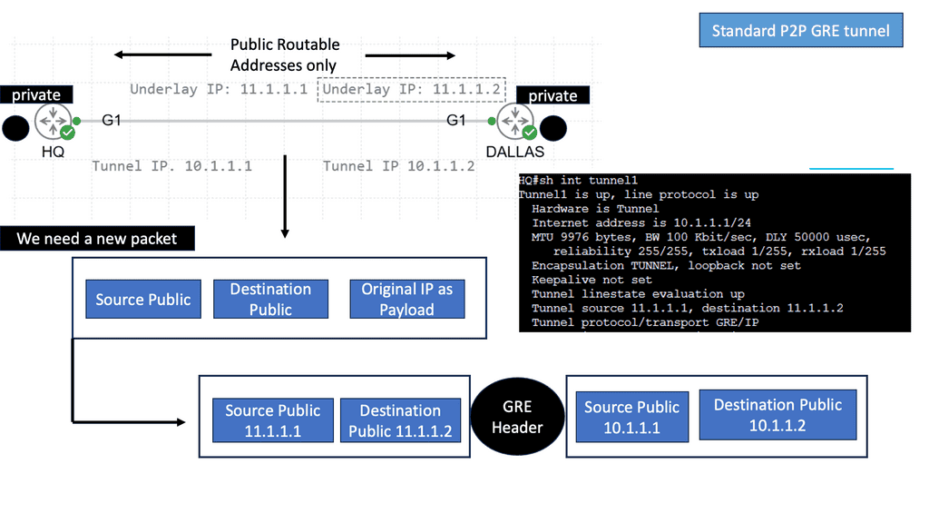
SDN is all about taking intensive network algorithms out of the hardware. Previously, in traditional networks, this was in individual hardware devices using control plane points in the data path. As a result, control points may become congested (for example – OSPF max neighbors reached). Customers lose capacity on the control plane front but not on the data plane. SDN is moving the intensive computation to off-the-shelf servers. MPLS networks attempt to use the same concepts with Route-Reflector (RR) designs.

They started to move route reflectors off the data plane to compute the best-path algorithms. Route reflectors can be positioned anywhere in the network and do not have to sit on the data path. Controller-based SDN approach, you are not embedding the control plane in the network. The controller is off the path. Now, you can scale out and SDN frameworks centrally provision and push policy down to the data plane.

Viptela can take any circuit and provide the ubiquitous connectivity MPLS provided, but now, it’s based on a policy with a central controller. Remote sites can have random transport methods. One leg could be the Internet, and the other could be MPLS. As long as there is an IP path between endpoint A and the controller, Viptela can provide the ubiquitous data plane.


Viptela SD WAN and Secure Extensible Network (SEN)

Managed overlay network

If you look at the existing WAN, it is two-part: routing and security. Routing connects sites, and security secures transmission. We have too many network security and policy configuration points in the current model. SEN allows you to centralize control plane security and routing, resulting in data path fluidity. The controller takes care of routing and security decisions.

It passes the relevant information between endpoints. Endpoints can pop up anywhere in the network. All they have to do is set up a control channel for the central controller. This approach does not build excessive control channels, as the control channel is between the controller and endpoints. Not from endpoint to endpoint. The data plane can flow based on the policy in the center of the network.

Viptela SD WAN


Viptela SD WAN: Deployment considerations

Deployment of separate data plane nodes at the customer site is integrated into existing infrastructure at Layer 2 or 3. So you can deploy incrementally, starting with one node and ending with thousands. It is so scalable because it is based on routed technology. The model allows you to deploy, for example, a guest network and then integrate it further into your network over time. Internally they use Border Gateway Protocol (BGP). One the data plane, they use standard IPSec between endpoints. It also works over Network Address Translation (NAT), meaning IPSec over UDP.
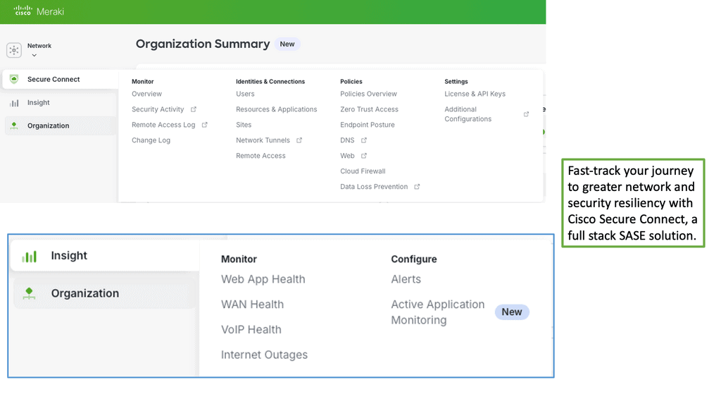
When an attacker gets access to your network, it is easy for them to reach the beachhead and hop from one segment to another. Viptela enables per-segment encryption, so even if they get to one segment, they will not be able to jump to another. Key management on a global scale has always been a challenge. Viptela solves this with a propitiatory distributed manager based on a priority system. Currently, their key management solution is not open to the industry.


SDN controller

You have a controller and VPN termination points i.e data plane points. The controller is the central management piece that assigns the policy. Data points are modules that are shipped to customer sites. The controller allows you to dictate different topologies for individual endpoint segments. Similar to how you influence-routing tables with RT in MPLS.

The control plane is at the controller.


Data plane module

Data plane modules are located at the customer site. They connect this data plane module, which could be a PE hand-off to the internal side of the network. The data plane module must be in the data plane path on the customer site. Internal side, they discover the routing protocols and participate in prefix learning. At Layer 2, they discover the VLANs. Their module can either be the default gateway or perform the router neighbor relationship function. WAN side, data plane module registers uplink IP address to WAN controller/orchestration system. The controller builds encrypted tunnels between the data endpoints. The encrypted control channels are only needed when you build over untrusted third parties.

If the problem occurs with controller connectivity, the on-site module can stop being the default gateway and usually participate in Layer 3 forwarding for existing protocols. It backs off from being the primary router for off-net traffic. It’s like creating VRF for different businesses and default routes for each VRF with a single peering point to the controller; Policy-Based Routing (PBR) for each VRF for data plane activity. The PBR is based on information coming from the controller. Each control segment can have a separate policy (for example – modifying the next hop). From a configuration point of view, you need an IP on the data plane module and the remote controller IP. The controller pushes down the rest.


  • Viptela SD WAN: Use cases

For example, you have a branch office with three distinct segments, and you want each endpoint to have its independent topology. The topology should be service driven, and the service should not follow existing defined topology. Each business should depict how they want their business to connect to the network team should not say this is how the topology is, and you must obey our topology.
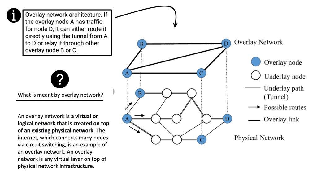
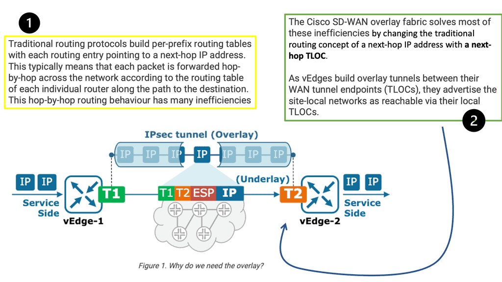
From a carrier’s perspective, they can expand their MPLS network to areas they do not have a physical presence. And bring customers with this secure overlay to their closest pop where they have an MPLS peering. MPLS providers can expand their footprint to areas where they do not have service. If MPLS has customers in region X and wants to connect to the customer in region Y, they can use Viptela. Having those different data plane endpoints through a security framework would be best before entering the MPLS network.

Viptela allows you to steer traffic based on the SLA requirements of the application, aka Application-Aware Routing. For example, if you have two sites with dual connectivity to MPLS and Internet, data plane modules (located at customer sites) nodes can steer traffic over either the MPLS or Internet transport based on end-to-end latency or drops. They do this by maintaining the real-time loss, latency, and jitter characteristics and then applying policies on the centralized controller. As a result, critical traffic is always steered to the most reliable link. This architecture can scale to 1000 nodes in a full mesh topology.
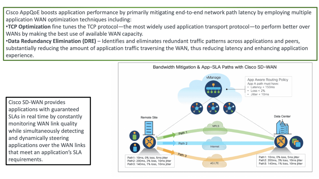
 

viptela sd wan