data center design

Open Networking

Open Networking

In today's digital age, connectivity is at the forefront of our lives. From smart homes to autonomous vehicles, the demand for seamless and reliable network connectivity continues to grow. This is where Open Networking comes into play. In this blog post, we will explore the concept of Open Networking, its benefits, and its impact on the future of technology.

Open Networking refers to separating hardware and software components of a network infrastructure. Traditionally, network equipment vendors provided closed, proprietary systems that limited flexibility and innovation.

However, with Open Networking, organizations can choose the hardware and software components that best suit their needs, fostering greater interoperability and driving innovation.

Table of Contents

Highlights: Open Networking

The Role of Transformation

To undertake an effective SDN data center transformation strategy, we must accept that demands on data center networks come from internal end-users, external customers, and considerable changes in the application architecture. All of which put pressure on traditional data center architecture.

Dealing effectively with these demands requires the network domain to become more dynamic, potentially introducing Open Networking and Open Networking solutions. We must embrace digital transformation and the changes it will bring to our infrastructure for this to occur. Unfortunately, keeping current methods is holding back this transition.

Modern Network Infrastructure

In modern network infrastructures, as has been the case on the server side for many years, customers demand supply chain diversification regarding hardware and silicon vendors. This diversification reduces the Total Cost of Ownership because businesses can drive better cost savings. In addition, replacing the hardware underneath can be seamless because the software above is standard across both vendors.

Further, as architectures streamline and spine leaf architecture increases from the data center to the backbone and the Edge, a typical software architecture across all these environments brings operational simplicity. This perfectly aligns with the broader trend of IT/OT convergence.  

Related: For pre-information, you may find the following posts helpful:

  1. OpenFlow Protocol
  2. Software-defined Perimeter Solutions
  3. Network Configuration Automation
  4. SASE Definition
  5. Network Overlays
  6. Overlay Virtual Networking


Open Networking Solutions

Key Open Networking Discussion points:


  • Popularity of Spine Leaf architecture.

  • Lack of fabric-wide automation.

  • Automation and configuration management.

  • Open networking vs open protocols.

  • Challenges with integrated vendors.

Back to Basics: Open Networking

SDN and an SDN Controller

SDN’s three concepts are:

  • Programmability.
  • The separation of the control and data planes.
  • Managing a temporary network state in a centralized control model, regardless of the degree of centralization.

So, we have an SDN controller. In theory, an SDN controller provides services that can realize a distributed control plane and abet temporary state management and centralization concepts. 

open networking
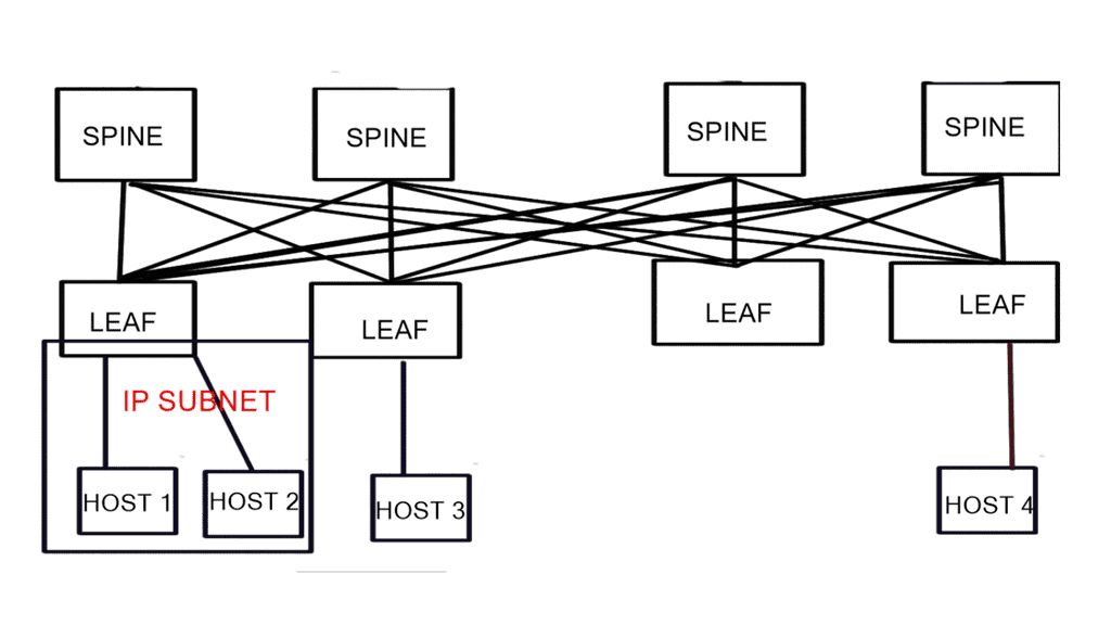
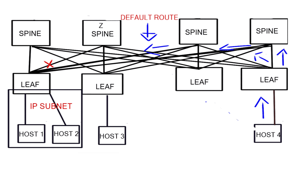
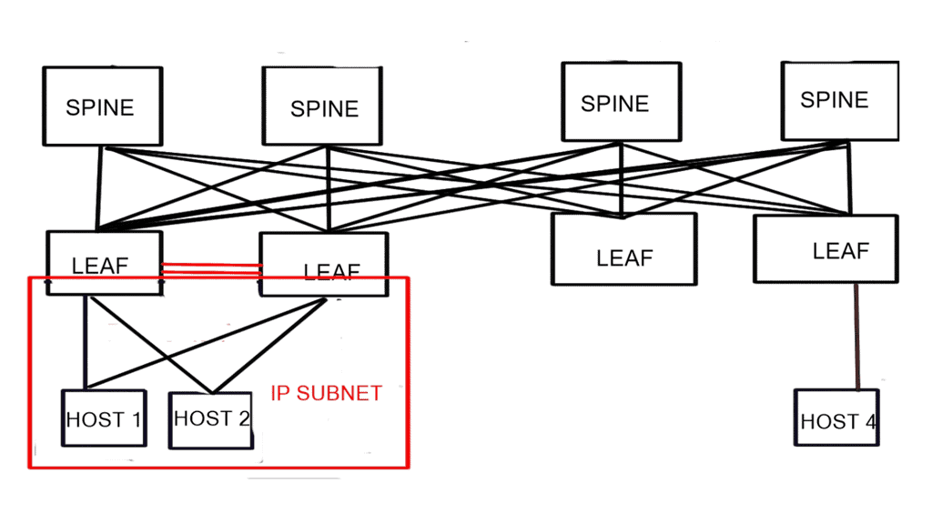
Diagram: Open Networking for a data center topology.

The Role of Zero Trust

Zero Trust Security Strategy

Zero Trust Security Main Components

  • Zero trust security is a paradigm shift in the way organizations approach their cybersecurity.

  • Every user, device, or application, regardless of its location, must undergo strict verification and authorization processes.

  • Organizations can fortify their defenses, protect sensitive data, and mitigate the risks associated with modern cyber threats.

♦ Benefits of Open Networking:

1. Flexibility and Customization: Open Networking enables organizations to tailor their network infrastructure to their specific requirements. By decoupling hardware and software, businesses can choose the best-of-breed components and optimize their network for performance, scalability, and cost-effectiveness.

2. Interoperability: Open Networking promotes interoperability by fostering open standards and compatibility between different vendors’ equipment. This allows organizations to build multi-vendor networks, reducing vendor lock-in and enabling seamless integration of network components.

3. Cost Savings: With Open Networking, organizations can lower their networking costs by leveraging commodity hardware and open-source software. This reduces capital expenditures and allows for more efficient network management and more effortless scalability.

4. Innovation and Collaboration: Open Networking encourages collaboration and innovation by providing a platform for developers to create and contribute to open-source networking projects. The community’s collective effort drives continuous improvements, leading to faster adoption of new technologies and features.

Open Networking in Practice:

Open Networking is already making its mark across various industries. Cloud service providers, for example, rely heavily on Open Networking principles to build scalable and flexible data center networks. Telecom operators also embrace Open Networking to deploy virtualized network functions, enabling them to offer services more efficiently and adapt to changing customer demands.

Moreover, adopting Software-Defined Networking (SDN) and Network Functions Virtualization (NFV) further accelerates the realization of Open Networking’s benefits. SDN separates the control plane from the data plane, providing centralized network management and programmability. NFV virtualizes network functions, allowing for dynamic provisioning and scalability.

Open Networking in Practice

Cloud service providers

Virtualized Network Function

Virtual Private Networks

Software-Defined Networking (SDN

Network Function Virtualization

Dynamic Provisioning and Scalability

Open-source network operating systems (NOS)

Leveraging White-box Switches

Reducing Vendor Lock-in

Freedom to choose best-of-breed components

Intent-based Networking

Network Virtualization


Open Networking Solutions

Open networking solutions: Data center topology

Now, let’s look at the evolution of data centers to see how we can achieve this modern infrastructure. So, to evolve and to be in line with current times, you should use technology and your infrastructure as practical tools. You will be able to drive the entire organization to become digital.

Of course, the network components will play a key role. Still, the digital transformation process is an enterprise-wide initiative focusing on fabric-wide automation and software-defined networking.

Open networking solutions: Lacking fabric-wide automation

One central pain point I have seen throughout networking is the necessity to dispense with manual work lacking fabric-wide automation. In addition, it’s common to deploy applications by combining multiple services that run on a distributed set of resources. As a result, configuration and maintenance are much more complex than in the past. You have two options to implement all of this.

First, you can connect up these services by, for example, manually spinning up the servers, installing the necessary packages, SSHing to each one, or you can go down the path of open network solutions with automation, in particular, Ansible automation with Ansible Engine or Ansible Tower with automation mesh. As automation best practice, use Ansible variables for flexible playbook creation that can be easily shared and used amongst different environments.  

Agility and the service provider

For example, in the case of a service provider that has thousands of customers, it needs to deploy segmentation to separate different customers. Traditionally, the technology of choice would be VRFs or even full-blown MPLS, which requires administrative touchpoints for every box.

As I was part of a full-blown MPLS design and deployment for a more significant service provider, the costs and time were extreme. Even when it is finally done, the design lacks agility compared to what you could have done with Open Networking.

This would include Provider Edge (PE) Edge routers at the Edge, to which the customer CPE would connect. And then, in the middle of the network, we would have what is known as P ( Provider ) routers that switch the traffic based on a label.

Although the benefits of label switching were easy to implement IPv6 with 6PE ( 6PE is a technique that provides global IPv6 reachability over IPv4 MPLS ) that overcomes many IPv6 fragmentation issues, we could not get away from the manual process without investing heavily again. It is commonly a manual process.

Fabric-wide automation and SDN

However, deploying a VRF or any technology, such as an anycast gateway, is a dynamic global command in a software-defined environment. We now have fabric-wide automation and can deploy with one touch instead of numerous box-by-box configurations.

Essentially, we are moving from a box-by-box configuration to the atomic programming of a distributing fabric of a single entity. The beauty is that we can carry out deployments with one configuration point quickly and without human error.

fabric wide automation
Diagram: Fabric wide automation.

Open networking solutions: Configuration management

Manipulating configuration files by hand is a tedious and error-prone task. Not to mention time-consuming. Equally, performing pattern matching to make changes to existing files is risky. The manual approach will result in configuration drift, where some servers will drift from the desired state.

Configuration drift is caused by inconsistent configuration items across devices, usually due to manual changes and updates and not following the automation path. Ansible architecture can maintain the desired state across various managed assets.

The managed assets that can range from distributed firewalls to Linux hosts are stored in what’s known as an inventory file, which can be static or dynamic inventory. Dynamic inventories are best suited for a cloud environment where you want to gather host information dynamically. Ansible is all about maintaining the desired state for your domain.

ansible automation
Diagram: Ansible automation.

The issue of Silos

To date, the networking industry has been controlled by a few vendors. We have dealt with proprietary silos in the data center, campus/enterprise, and service provider environments. The major vendors will continue to provide a vertically integrated lock-in solution for most customers. They will not allow independent, 3rd party network operating system software to run on their silicon.

Typically, these silos were able to solve the problems of the time. The modern infrastructure needs to be modular, open, and straightforward. Vendors need to allow independent, 3rd party network operating systems to run on their silicon to break from being a vertically integrated lock-in solution.

Cisco has started this for the broader industry regarding open networking solutions with the announcement of the Cisco Silicon ONE. 

network overlay
Diagram: The issue of vendor lock-in.

The Rise of Open Networking Solutions

New data center requirements have emerged; therefore, the network infrastructure must break the silos and transform to meet these trending requirements. One can view the network transformation as moving from a static and conservative mindset that results in cost overrun and inefficiencies to a dynamic routed environment that is simple, scalable, secure, and can reach the far edge. For effective network transformation, we need several stages. 

Firstly, transition to a routed data center design with a streamlined leaf-spine architecture. Along with a standard operating system across cloud, Edge, and 5G networks. A viable approach would be for all of this to be done with open standards, without proprietary mechanisms. Then, we need good visibility.

The need for visibility

As part of the transformation, the network is no longer considered a black box that needs to be available and provide connectivity to services. Instead, the network is a source of deep visibility that can aid a large set of use cases: network performance, monitoring, security, and capacity planning, to name a few. However, visibility is often overlooked with an over-focus on connectivity and not looking at the network as a valuable source of information.

Network management
Diagram: The requirement for deep visibility.

Monitoring a network: Flow level

For efficient network management, we must provide deep visibility for the application at a flow level on any port and device type. Today, you would deploy a redundant monitoring network if you want anything comparable. Such a network would consist of probes, packet brokers, and tools to process the packet for metadata.

The traditional network monitoring tools, such as packet brokers, require life cycle management. A more viable solution would integrate network visibility into the fabric and would not need many components. This enables us to do more with the data and aids with agility for ongoing network operations.

There will always be some requirement for application optimization or a security breach, where visibility can help you quickly resolve these issues.

Monitoring is used to detect known problems and is only valid with pre-defined dashboards with a problem you have seen before, such as capacity reaching its limit. On the other hand, we have the practices of Observability that can detect unknown situations and is used to aid those in getting to the root cause of any problem, known or unknown: Observability vs Monitoring

Evolution of the Data Center

We are transitioning, and the data center has undergone several design phases. Initially, we started with layer 2 silos, suitable for the north-to-south traffic flows. However, layer 2 designs hindered east-west communication traffic flows of modern applications and restricted agility, which led to a push to break network boundaries.

Hence, there is a move to routing at the Top of the Rack (ToR) with overlays between ToR to drive inter-application communication. This is the most efficient approach, which can be accomplished in several ways. 

The leaf spine “clos” popularity

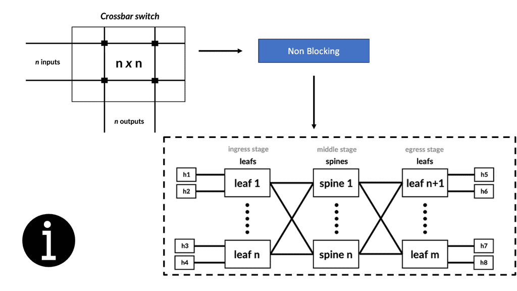
The demand for leaf and spine “clos” started in the data center and spread to other environments. A clos network is a type of non-blocking, multistage switching architecture. This network design extends from the central/backend data center to the micro data centers at the EdgeEdge. Various parts of the edge network, PoPs, central offices, and packet core have all been transformed into leaf and spine “clos” designs. 

leaf spine
Diagram: Leaf Spine.

The network overlay

Building a complete network overlay is common to all software-defined technologies when increasing agility. An overlay is a solution that is abstracted from the underlying physical infrastructure. This means separating and disaggregating the customer applications or services from the network infrastructure. Think of it as a sandbox or private network for each application that is on an existing network.

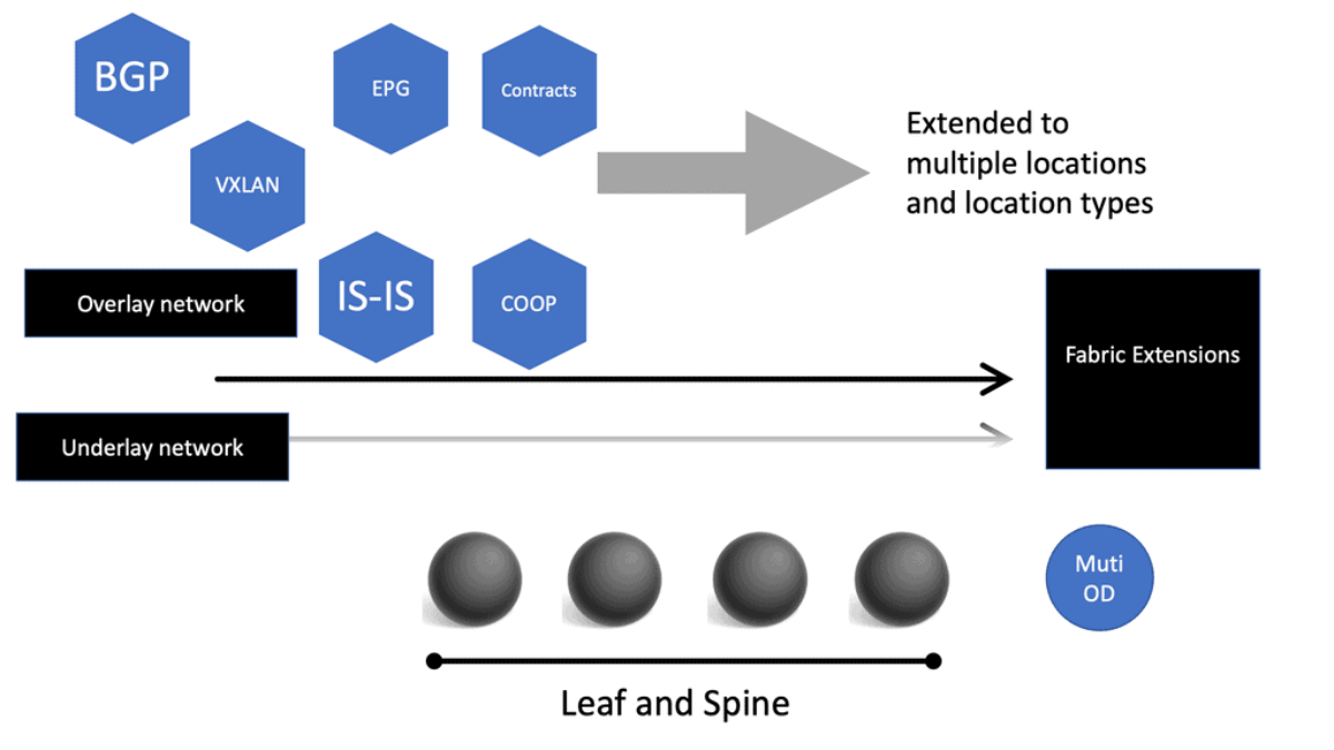
More often, the network overlay will be created with VXLAN. The Cisco ACI uses an ACI network of VXLAN for the overlay, and the underlay is a combination of BGP and IS-IS. The overlay abstracts a lot of complexity, and Layer 2 and 3 traffic separation is done with a VXLAN network identifier (VNI).

The VXLAN overlay

VXLAN uses a 24-bit network segment ID, called a VXLAN network identifier (VNI), for identification. This is much larger than the 12 bits used for traditional VLAN identification. The VNI is just a fancy name for a VLAN ID, but it now supports up to 16 Million VXLAN segments. 

This is considerably more than the traditional 4094 supported endpoints with VLANs. Not only does this provide more hosts, but it enables better network isolation capabilities, having many little VXLAN segments instead of one large VLAN domain.

The VXLAN network has become the de facto overlay protocol and brings many advantages to network architecture regarding flexibility, isolation, and scalability. VXLAN effectively implements an Ethernet segment virtualizing a thick Ethernet cable.

VXLAN unicast mode

Traditional policy deployment

Traditionally, deploying an application to the network involves propagating the policy to work through the entire infrastructure. Why? Because the network acts as an underlay, segmentation rules configured on the underlay are needed to separate different applications and services.

This creates a rigid architecture that cannot react quickly and adapt to changes, therefore lacking agility. The applications and the physical network are tightly coupled. Now, we can have a policy in the overlay network with proper segmentation per customer.

How VXLAN works: ToR

What is VXLAN? Virtual networks and those built with VXLAN are built from servers or ToR switches. Either way, the underlying network transports the traffic and doesn’t need to be configured to accommodate the customer application. That’s all done in the overlay, including the policy. Everything happens in the overlay network, which is most efficient when done in a fully distributed manner.

Overlay networking
Diagram: Overlay Networking with VXLAN

Now, application and service deployment occurs without touching the physical infrastructure. For example, if you need to have Layer 2 or Layer 3 paths across the data center network, you don’t need to tweak a VLAN or change routing protocols.

Instead, you add a VXLAN overlay network. This approach removes the tight coupling between the application and network, creating increased agility and simplicity in deploying applications and services.

the network overlay
Diagram: The VXLAN overlay network.

Extending from the data center

Edge computing creates a fundamental disruption among the business infrastructure teams. We no longer have the framework where IT only looks at the backend software, such as Office365, and OT looks at the routing and switching product-centric elements. There is convergence.

Therefore, you need a lot of open APIs. The edge computing paradigm brings processing closer to the end devices. This reduces the latency and improves the end-user experience. It would help if you had a network that could work with this model to support this. Having different siloed solutions does not work. 

Common software architecture

So the data center design went from the layer 2 silo to the leaf and spine architecture with routing to the ToR. However, there is another missing piece. We need a standard operating software architecture across all the domains and location types for switching and routing to reduce operating costs. The problem remains that even on one site, there can be several different operating systems.

Through recent consultancy engagements, I have experienced the operational challenge of having many Cisco operating systems on one site. For example, I had an IOS XR for service provider product lines, IOS XE for enterprise, and NS OX for the data center, all on a single site.

Open networking solutions and partially open-source 

Some major players, such as Juniper, started with one operating system and then fragmented significantly. It’s not that these are not great operating systems. Instead, it would be best if you partitioned into different teams, often a team for each operating system.

Standard operating system software provides a seamless experience across the entire environment. Therefore, your operational costs go down, your ability to use software for the specific use cases you want goes up, and you can reduce the cost of ownership. In addition, this brings Open Networking and partially open source.

What Is Open Networking

The traditional integrated vendor

Traditionally, networking products were a combination of hardware and software that had to be purchased as an integrated solution. Open networking, on the other hand, disaggregates hardware from software. They were allowing IT to mix and match at will.

With Open Networking, we are not reinventing how packets are forwarded or routers communicate. With Open Networking solutions, you are never alone and never the only vendor. The value of software-defined networking and Open Networking is doing as much as possible in software so you don’t depend on delivering new features from a new generation of hardware. If you want a new part, it’s quickly implemented in software without swapping the hardware or upgrading line cards.

Move intelligence to software.

You want to move as much intelligence as possible into software, thus removing the intelligence from the physical layer. You don’t want to build in hardware features; you want to use the software to provide the new features. This is a critical philosophy and is the essence of Open Networking. Software becomes the central point of intelligence, not the hardware; this intelligence is delivered fabric-wide.

As we have seen with the rise of SASE. From the customer’s point of view, they get more agility as they can move from generation to generation of services without having hardware dependency and don’t have the operational costs of constantly swapping out the hardware.

SDN network

Open Networking Solutions and Open Networking Protocols

Some vendors build into the hardware the differentiator of the offering. For example, with different hardware, you can accelerate the services. With this design, the hardware level is manipulated to make improvements but does not use standard Open Networking protocols. 

When you look at your hardware to accelerate your services, the result is that you are 100% locked and unable to move as the cost of moving is too much. You could have numerous generations of, for example, line cards, and all have different capabilities, resulting in a complex feature matrix.

It is not that I’m against this, and I’m a big fan of the prominent vendors, but this is the world of closed networking, which has been accepted as the norm until recently. So you must adapt and fit; we need to use open protocols.

Open networking is a must; open source is not.

The proprietary silo deployments led to proprietary alternatives to the prominent vendors. This meant that the startups and options offered around ten years ago were playing the game on the same pitch as the incumbents. Others built their software and architecture by, for example, saying the Linux network subsystem and the OVS bridge are good enough to solve all data center problems.

With this design, you could build small PoPs with layer 2. But the ground shifts as the design requirements change to routing. So, let’s glue the Linux kernel and Quagga FRRouting (FRR) and devise a routing solution. Unfortunately, many didn’t consider the control plane architecture or the need for multiple data center use cases.

Limited scale

Gluing the operating system and elements of open-source routing provides a limited scale and performance and results in operationally intensive and expensive solutions. The software is built to support the hardware and architectural demands.

Now, we see a lot of open-source networking vendors tackling this problem from the wrong architectural point of view, at least from where the market is moving to. It is not composable, microservices-based, or scalable from an operational viewpoint.

There is a difference between open source and Open Networking. The open-source offerings (especially the control plane) have not scaled because of sub-optimal architectures. 

On the other hand, Open Networking involves building software from first principles using modern best practices, with Open API (e.g., OpenConfig/NetConf) for programmatic access without compromising on the massive scale-up and scale-out requirements of modern infrastructure.

SDN Network Design Options

We have both controller and controllerless options. With a controllerless solution, setup is faster, increases agility, and provides robustness in single-point-of-failure, particularly for out-of-band management, i.e., connecting all the controllers.

A controllerless architecture is more self-healing; anything in the overlay network is also part of the control plane resilience. An SDN controller or controller cluster may add complexity and impede resiliency. Since the network depends on them for operation, they become a single point of failure and can impact network performance. The intelligence kept in a controller can be a point of attack.

So, there are workarounds where the data plane can continue forward without an SDN controller but always avoid a single point of failure or complex ways to have a quorum in a control-based architecture.

software defined architecture
Diagram: Software defined architecutre.

Software Defined Architecture & Automation

We have two main types of automation to consider. Day 0 and days 1-2. First and foremost, day 0 automation simplifies and reduces human error when building the infrastructure. Days 1-2 touch the customer more. This may include installing services quickly on the fabric, e.g., VRF configuration and building Automation into the fabric. 

Day 0 automation

As I said, day 0 automation builds basic infrastructures, such as routing protocols and connection information. These stages need to be carried out before installing VLANs or services. Typical tools software-defined networking uses are Ansible or your internal applications to orchestrate the build of the network.

These are known as fabric automation tools. Once the tools discover the switches, the devices are connected in a particular way, and the fabric network is built without human intervention. It simplifies traditional automation, which is helpful in day 0 automation environments.

Configuration Management

Ansible is a configuration management tool that can help alleviate manual challenges. Ansible replaces the need for an operator to tune configuration files manually and does an excellent job in application deployment and orchestrating multi-deployment scenarios.  

Ansible configuration
Diagram: Ansible Configuration

Pre-deployed infrastructure

Ansible does not deploy the infrastructure; you could use other solutions like Terraform that are best suited for this. Terraform is infrastructure as a code tool. Ansible is often described as a configuration management tool and is typically mentioned along the same lines as Puppet, Chef, and Salt. However, there is a considerable difference in how they operate.

Most notably, the installation of agents. Ansible automation is relatively easy to install as it is agentless. The Ansible architecture can be used in large environments with Ansible Tower using the execution environment and automation mesh. I have recently encountered an automation mesh, a powerful overlay feature that enables automation closer to the network’s edge.

Current and desired stage [ YAML playbooks, variables ]

Ansible ensures that the managed asset’s current state meets the desired state. Ansible is all about state management. It does this with Ansible Playbooks, more specifically, YAML playbooks. A playbook is a term Ansible uses for a configuration management script and ensuring the desired state is met. Essentially, playbooks are Ansible’s configuration management scripts. 

open networking solutions
Diagram: Configuration management.

Day 1-2 automation

With day 1-2 automation, SDN does two things.

Firstly, the ability to install or provision services automatically across the fabric. With one command, human error is eliminated. The fabric synchronizes the policies across the entire network. It automates and disperses the provisioning operations across all devices. This level of automation is not classical, as this strategy is built into the SDN infrastructure. 

Secondly, it integrates network operations and services with virtualization infrastructure managers such as OpenStack, VCenter, OpenDaylight, or, at an advanced level, OpenShift networking SDN. How does the network adapt to the instantiation of new workloads via the systems? The network admin should not even be in the loop if, for example, a new virtual machine (VM) is created. 

There should be a signal that a VM with specific configurations should be created, which is then propagated to all fabric elements. You shouldn’t need to touch the network when the virtualization infrastructure managers provide a new service. This represents the ultimate in agility as you are removing the network components. 

The first steps of creating a software-defined data center

It is agreed that agility is a necessity. So, what is the prime step? One critical step is creating a software-defined data center that will allow the rapid deployment of computing and storage for workloads. In addition to software-defined computing and storage, the network must be automated and not be an impediment. 

The five critical layers of technology

To achieve software-defined agility for the network, we need an affordable solution that delivers on four essential layers of technology:

  1. Comprehensive telemetry/granular visibility into endpoints and traffic traversing the network fabric for performance monitoring and rapid troubleshooting.
  2. Network virtualization overlay, like computer virtualization, abstracts the network from the physical hardware for increased agility and segmentation.
  3. Software-defined networking (SDN) involves controlling and automating the physical underlay to eliminate the mundane AND error-prone box-by-box configuration.
  4. Open network underlay is a cost-effective physical infrastructure with no proprietary hardware lock-in that can leverage open source.
  5. Open Networking solutions are a must, as understanding the implications of open source in large, complex data center environments is essential.

The Future of Open Networking:

Open Networking will be crucial in shaping the future as technology evolves. The rise of 5G, the Internet of Things (IoT), and artificial intelligence (AI) will require highly agile, scalable, and intelligent networks. Open Networking’s flexibility and interoperability will meet these demands and enable a connected future.

Summary: Open Networking

Networking is vital in bringing people and ideas together in today’s interconnected world. Traditional closed networks have their limitations, but with the emergence of open networking, a new era of connectivity and collaboration has dawned. This blog post explored the concept of open networking, its benefits, and its impact on various industries and communities.

Section 1: What is Open Networking?

Open networking uses open standards, open-source software, and open APIs to build and manage networks. Open networking promotes interoperability, flexibility, and innovation, unlike closed networks that rely on proprietary systems and protocols. It allows organizations to customize and optimize their networks based on their unique requirements.

Section 2: Benefits of Open Networking

2.1 Enhanced Scalability and Agility

Open networking enables organizations to scale their networks more efficiently and adapt to changing needs. Decoupling hardware and software makes adding or removing network components easier, making the network more agile and responsive.

2.2 Cost Savings

With open networking, organizations can choose hardware and software components from multiple vendors, promoting competition and reducing costs. This eliminates vendor lock-in and allows organizations to use cost-effective solutions without compromising performance or reliability.

2.3 Innovation and Collaboration

Open networking fosters innovation by encouraging collaboration among vendors, developers, and users. Developers can create new applications and services that leverage the network infrastructure with open APIs and open-source software. This leads to a vibrant ecosystem of solutions that continually push the boundaries of what networks can achieve.

Section 3: Open Networking in Various Industries

3.1 Telecommunications

Open networking has revolutionized the telecommunications industry. Telecom operators can now build and manage their networks using standard hardware and open-source software, reducing costs and enabling faster service deployments. It has also paved the way for adopting virtualization technologies like Network Functions Virtualization (NFV) and Software-Defined Networking (SDN).

3.2 Data Centers

In the world of data centers, open networking has gained significant traction. Data center operators can achieve greater agility and scalability by using open standards and software-defined networking. Open networking also allows for better integration with cloud platforms and the ability to automate network provisioning and management.

3.3 Enterprise Networks

Enterprises are increasingly embracing open networking to gain more control over their networks and reduce costs. Open networking solutions offer greater flexibility regarding hardware and software choices, enabling enterprises to tailor their networks to meet specific business needs. It also facilitates seamless integration with cloud services and enhances network security.

Conclusion:

Open networking has emerged as a powerful force in today’s digital landscape. Its ability to promote interoperability, scalability, and innovation makes it a game-changer in various industries. Whether revolutionizing telecommunications, transforming data centers, or empowering enterprises, open networking connects the world in ways we never thought possible.

Cisco ACI

Cisco ACI | ACI Infrastructure

Cisco ACI | ACI Infrastructure

The ACI Cisco stands for Cisco Application Centric Infrastructure and is based on a spine leaf architecture. It is a software-defined networking solution that provides a holistic approach to network management. ACI offers a centralized policy-driven framework for managing and automating network infrastructure.

One of the critical features of ACI Cisco is its ability to create a virtualized network environment using the Application Network Profiles (ANPs) concept. ANPs allow administrators to define and manage network policies based on the requirements of specific applications.

This simplifies the deployment and management of applications, as network policies can be easily applied across the entire infrastructure.

Table of Contents

Highlights: ACI Cisco

Example: ACI Networks

ACI Networks also introduces the concept of the Application Policy Infrastructure Controller (APIC), which acts as the central point of control for the network. The APIC allows administrators to define and enforce network policies, monitor performance, and troubleshoot issues.

In addition to network virtualization and policy management, ACI Cisco offers a range of other features. These include integrated security, intelligent workload placement, and seamless integration with other Cisco products and technologies.

COOP Protocol in ACI

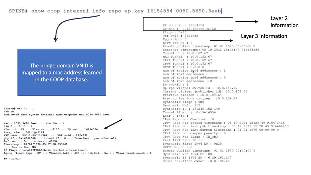
The spine proxy receives mapping information (location and identity) via the Council of Oracle Protocol (COOP). Using Zero Message Queue (ZMQ), leaf switches forward endpoint address information to spine switches. As part of COOP, the spine nodes maintain a consistent copy of the endpoint address and location information and maintain the distributed hash table (DHT) database for mapping endpoint identity to location.

Micro-segmentation

Integrated security is achieved through micro-segmentation, which allows administrators to define fine-grained security policies at the application level. This helps to prevent the lateral movement of threats within the network and provides better protection against attacks.

Intelligent workload placement ensures that applications are placed in the most appropriate locations within the network based on their specific requirements. This improves application performance and resource utilization.

Related: For pre-information, you may find the following helpful:

  1. Data Center Security
  2. Data Center Topologies
  3. Dropped Packet Test
  4. DMVPN
  5. Stateful Inspection Firewall
  6. Cisco ACI Components


ACI Network


Key Cisco ACI Blog Discussion Points:


  • Operates over a Leaf and Spine design.

  • New ACI network components e.g Bridge Domain and Contracts.

  • Intelligence at the edge.

  • Overcomes many DC challenges.

  • VXLAN transport network.

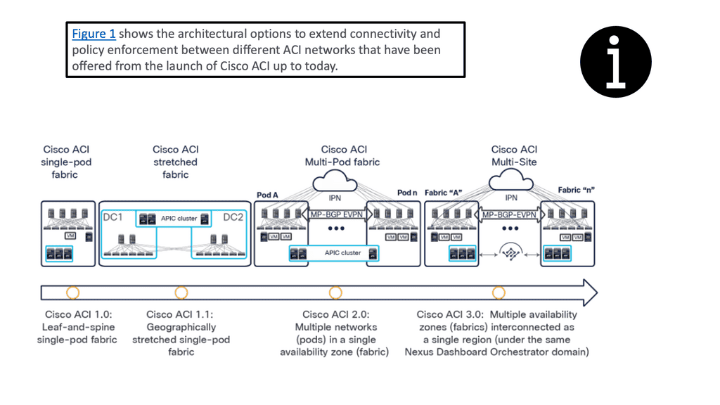
  • Extend with Mutli Pod and Multi Site.


ACI Components

Key components that make up the ACI Cisco architecture. By understanding these components, network administrators and IT professionals can harness the power of ACI to optimize their data center operations.

Cisco ACI Components

Main ACI Components

Cisco Application Centric Infrastructure (ACI) 

  • Application Policy Infrastructure Controller

  • Spine Switches

  • Leaf Switches

  • Application Network Profiles

  • Endpoint Groups 

1. Application Policy Infrastructure Controller (APIC):

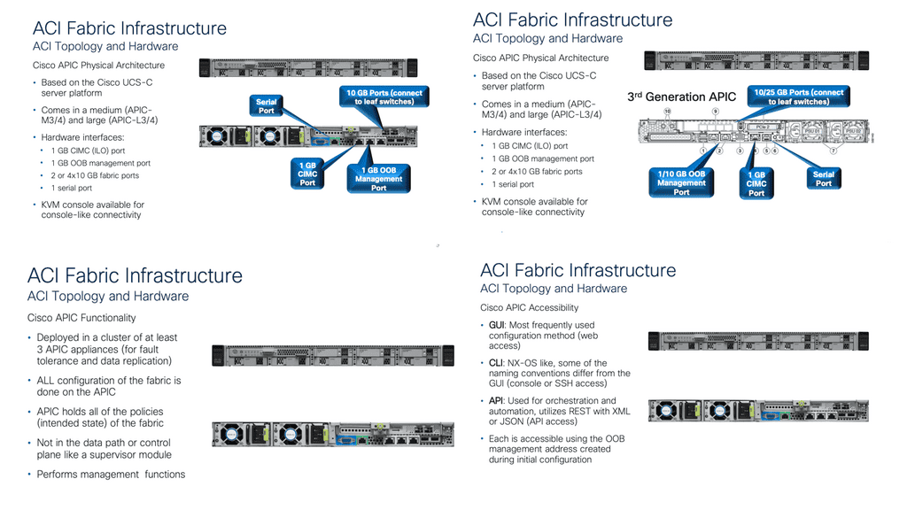
The cornerstone of the Cisco ACI architecture is the Application Policy Infrastructure Controller (APIC). APIC is the central management and policy engine for the entire ACI fabric. It provides a single point of control, enabling administrators to define and enforce policies that govern the behavior of applications and services within the data center. APIC offers a user-friendly interface for policy configuration, monitoring, and troubleshooting, making it an essential component for managing the ACI fabric.

2. Spine Switches:

Spine switches form the backbone of the ACI fabric. These high-performance switches provide connectivity between leaf switches and facilitate east-west traffic within the fabric. Spine switches operate at Layer 3 and use routing protocols to distribute traffic across the fabric efficiently. With the ability to handle massive amounts of data, spine switches ensure high-speed connectivity and optimal performance in the ACI environment.

3. Leaf Switches:

Leaf switches act as the access layer switches in the ACI fabric. They connect directly to the endpoints, such as servers, storage devices, and other network devices, and serve as the entry and exit points for traffic entering and leaving the fabric. Leaf switches provide Layer 2 connectivity for endpoint devices and Layer 3 connectivity for communication between endpoints within the fabric. They also play a crucial role in implementing policy enforcement and forwarding traffic based on predefined policies.


Lab Guide: IS-IS

Example: IS-IS

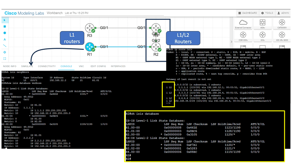
Cisco ACI under the covers runs ISIS. The ISIS routing protocol is an Interior Gateway Protocol (IGP) that enables routers within a network to exchange routing information and make informed decisions on the best path to forward packets. It operates at the OSI model’s Layer 2 (Data Link Layer) and Layer 3 (Network Layer).

ISIS organizes routers into logical groups called areas, simplifying network management and improving scalability. It allows for hierarchical routing, reducing the overhead of exchanging routing information across large networks.

Note:

Below, we have four routers. R1 and R2 are in area 12, and R3 and R4 are in area 34. R1 and R3 are intra-area routers, so that they will be configured as level 1 routers. R2 and R4 form the backbone, so that these routers will be configured as levels 1-2.

Network administrators need to configure ISIS parameters on each participating router to implement ISIS. These parameters include the router’s ISIS system ID, area assignments, and interface settings. ISIS uses the reliable transport protocol (RTP) to exchange routing information between routers.

Routing Protocol
Diagram: Routing Protocol. ISIS.

4. Application Network Profiles (ANPs):

Application Network Profiles (ANPs) are a key component of the Cisco ACI policy model. ANPs define the policies and configurations required for specific applications or application groups. ANPs encapsulate all the necessary information, including network connectivity, quality of service (QoS) requirements, security policies, and service chaining.

By associating endpoints with ANPs, administrators can easily manage and enforce consistent policies across the ACI fabric, simplifying application deployment and ensuring compliance.

5. Endpoint Groups (EPGs):

Endpoint Groups (EPGs) are logical containers that group endpoints with similar network requirements. EPGs provide a way to define and enforce policies at a granular level—endpoints within an EPG share standard policies, such as security, QoS, and network connectivity.

This grouping allows administrators to apply policies consistently to specific endpoints, regardless of their physical location within the fabric. EPGs enable seamless application mobility and simplify policy enforcement within the ACI environment.


Specific ACI Cisco architecture.

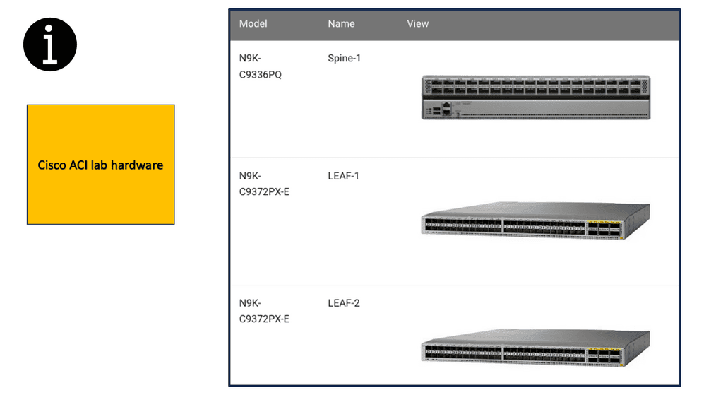
In some of the lab guides we have in this blog post. We are using the following hardware from a rack rental from Cloudmylabs. Remember that the ACI Fabric is built on the Nexus 9000 Product Family.

The Cisco Nexus 9000 Series Switches are designed to meet the increasing demands of modern networks. With high-performance capabilities, these switches deliver exceptional speeds and low latency, ensuring smooth and uninterrupted data flow. They support high-density 10/25/40/100 Gigabit Ethernet interfaces, allowing businesses to scale and adapt to growing network requirements.

Enhanced Security

The Cisco Nexus 9000 Series Switches offer comprehensive security features to protect networks from evolving threats. They leverage Cisco TrustSec technology, which provides secure access control, segmentation, and policy enforcement. With integrated security features, businesses can mitigate risks and safeguard critical data, ensuring peace of mind.

Application Performance Optimization:

To meet the demands of modern applications, the Cisco Nexus 9000 Series Switches are equipped with advanced features that optimize application performance. These switches support Cisco Tetration Analytics, which provides deep insights into application behavior, enabling businesses to enhance performance, troubleshoot issues, and improve efficiency.

Diagram: The source is Cloudmylabs.

Cisco ACI Simulator

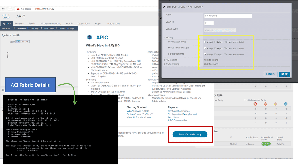
Below is a screenshot from Cisco ACI similar. At the start, you will be asked for fabric details. Remember that once you set the out-of-band management address for the API, you need to change the port group settings on the ESXi VM network. If you don’t change “Promiscuous mode, MAC address changes, and Forged Transmits,” you cannot access the UI from your desktop.

ACI fabric Details
Diagram: Cisco ACI fabric Details

Back to basics: Leaf and spine design

Leaf and Spine

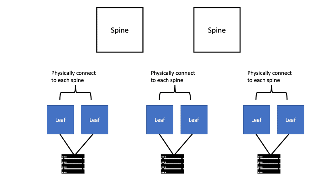
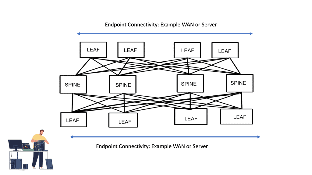
Leaf and spine architecture is a network design methodology commonly used in data centers. It provides a scalable and resilient infrastructure that can handle the increasing demands of modern applications and services. The term “leaf and spine” refers to the physical and logical structure of the network.

In leaf and spine architecture, the network is divided into two main layers: the leaf and spine layers. The leaf layer consists of leaf switches connected to the servers or endpoints in the data center. These leaf switches act as the access points for the servers, providing high-bandwidth connectivity and low-latency communication.

The spine layer, on the other hand, consists of spine switches that connect the leaf switches. The spine switches provide high-speed and non-blocking interconnectivity between the leaf switches, forming a fully connected fabric. This allows for efficient and predictable traffic patterns, as any leaf switch can communicate directly with any other leaf switch through the spine layer.


 Lab Guide: ACI Cisco with leaf and spine.

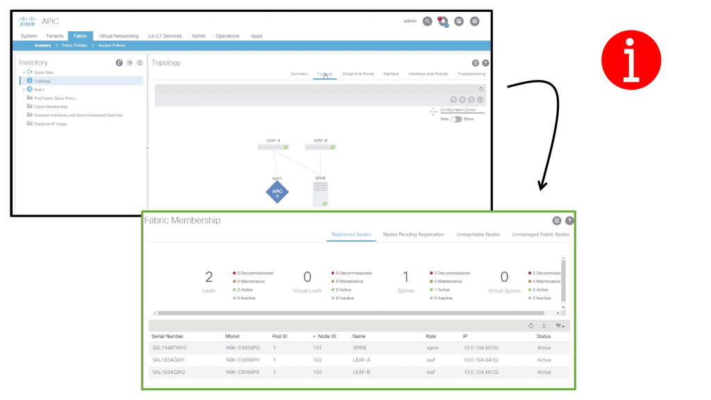
The following lab guide has a leaf and spine ACI design that includes 2 leaf switches acting as the leaf layer where the workloads connect. Then, we have a spine connected to the leaf. When the ACI hardware installation is done, all Spines and Leafs are linked and powered up. Once the basic configuration of APIC is completed, the Fabric discovery process starts working.

Note: IFM process

In the discovery process, ACI uses the Intra-Fabric Messaging (IFM) process in which APIC and nodes exchange heartbeat messages.

The process used by the APIC to push policy to the fabric leaf nodes is called the IFM Process. ACI Fabric discovery is completed in three stages. The leaf node directly connected to the APIC is discovered in the first stage. The second discovery stage brings in the spines connected to that initial leaf where APIC was connected. The third stage involves discovering the cluster’s other leaf nodes and APICs.

The fabric membership diagram below shows the inventory, including serial number, Pod, Node ID, Model, Role, Fabric IP, and Status. Cisco ACI consists of the following hardware components: APIC Controller Spine Switches and Leaf Switches.

ACI fabric discovery
Diagram: ACI fabric discovery

Analysis:

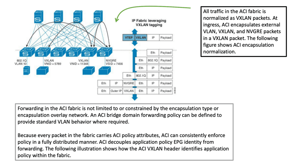
Cisco ACI uses an overlay based on VXLAN to virtualize physical infrastructure. Like most overlays, this overlay requires the data path at the network’s edge to map from the tenant end-point address in the packet, otherwise referred to as its identifier, to the endpoint’s location, also known as its locator. This mapping occurs in a tunnel endpoint (TEP) function called VXLAN (VTEP).

The VTEP addresses are displayed in the INFRASTRUCTURE IP column. The TEP address pool 10.0.0.0/16 has been configured on the Cisco APIC using the initial setup dialog. The APIC assigns the TEP addresses to the fabric switches via DHCP, so the infrastructure IP addresses in your fabric will differ from the figure.

This configuration is perfectly valid for a Lab but not good for a production environment. The minimum physical fabric hardware for a production environment includes two spines, two leaves, and three APICs.In addition to discovering and configuring the Fabric and applying the Tenant design, the following functionality can be configured:

  • Routing at Layer 3

  • Connecting a legacy network at layer 2

  • Virtual Port Channels at Layer 2

A note about Border Leafs: ACI fabrics often use this designation along with “Compute Leafs” and “Storage Leafs.” Border Leaf is merely a convention for identifying the leaf pair that hosts all external connectivity external to the fabric (Border Leaf) or the leaf pair that hosts host connectivity (Compute Leaf).

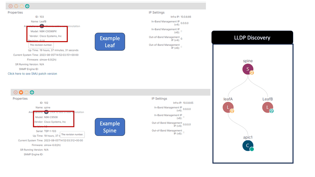
Note: The Link Layer Discovery Protocol (LLDP) is responsible for discovering directly adjacent neighbors. When run between the Cisco APIC and a leaf switch, it precedes three other processes: Tunnel endpoint (TEP) IP address assignment, node software upgrade (if necessary), and the intra-fabric messaging (IFM) process, which the Cisco APIC uses to push policy to the leaves.

aci Cisco LLDP

Leaf and Spine: Traffic flows

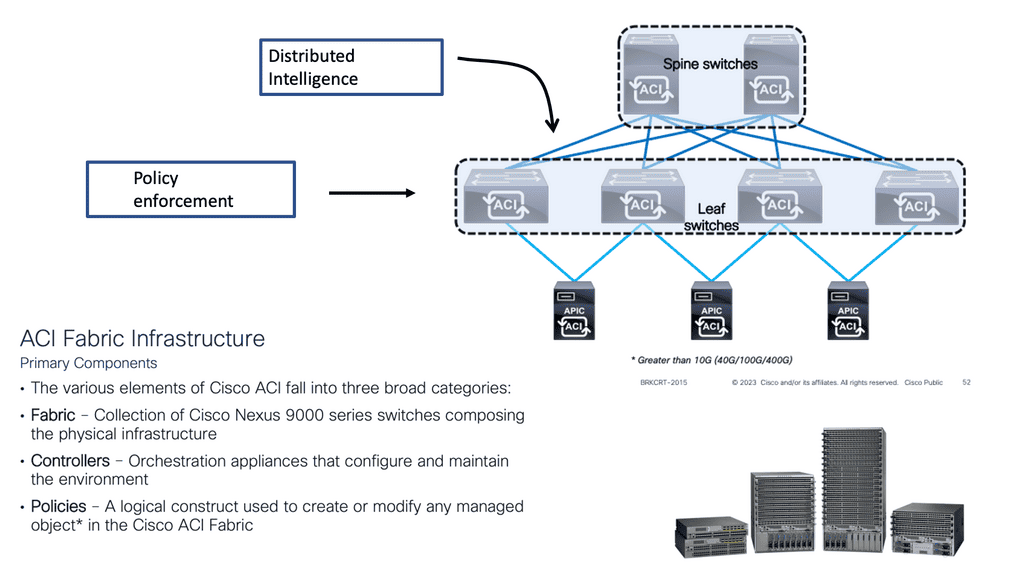
The leaf and spine network topology is suitable for east-to-west network traffic and comprises leaf switches to which the workloads connect and spine switches to which the leaf switches connect. The spines have a simple role to play and are geared around performance, while all the intelligence is distributed to the edge of the network where the leaf layers sit.

This allows engineers to move away from managing individual devices and manage the data center architecture more efficiently with policy. In this model, the Application Policy Infrastructure Controller (APIC) controllers can correlate information from the entire fabric.

Understanding Leaf and Spine Traffic Flow

In a leaf and spine architecture, traffic flow follows a structured path. When a device connected to a leaf switch wants to communicate with another device, the traffic is routed through the spine switch to the destination leaf switch. This approach minimizes the hops required for data transmission and reduces latency. Additionally, traffic can be evenly distributed since every leaf switch is connected to every spine switch, preventing congestion and bottlenecks.

Lab guide on ACI Cisco with leaf and spine.

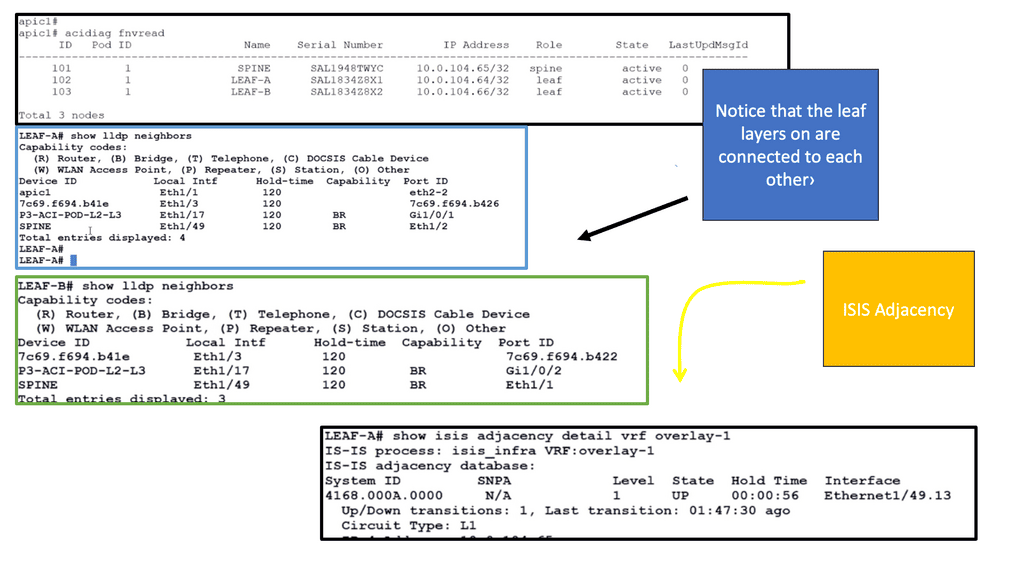
In the following lab guide, we continue to verify the ACI leaf and spine.  We can run the command Acidiag fnvread, a diagnostics tool to check the ACI fabric. It would also be recommended to check the LLDP and ISIS adjacencies. With a leaf and spine design, the leaf layer does not connect, and we can see this with the LLDP and ISIS adjacency information below.

ACI leaf and spine
Diagram: ACI leaf and spine
 

Advantages of Leaf and Spine Traffic Flow:

  • Improved Performance: Leaf and spine architecture ensures optimal performance by evenly distributing traffic and minimizing latency. This results in faster data transmission and improved response times for end-users.
  • Scalability: The leaf and spine architecture allows for easy scalability as additional leaf switches can be added without disrupting the existing network. This flexibility enables networks to adapt to changing requirements and handle increasing traffic loads.
  • High Availability: Providing multiple paths for traffic, leaf, and spine architecture ensures redundancy and fault tolerance. If one link fails, traffic can be rerouted through alternative paths, minimizing downtime and ensuring uninterrupted connectivity.

leaf and spine


Leaf and Spine Switch Functions

Based on a two-tier (spine and leaf switches) or three-tier (spine switch, tier-1 leaf switch, and tier-2 leaf switch) architecture, Cisco ACI switches provide the following functions:

Leaf switches: 

What are Leaf Switches?

Leaf switches connect between end devices, servers, and the network fabric. They are typically deployed in leaf-spine network architecture, connecting directly to the spine switches. Leaf switches provide high-speed, low-latency connectivity to end devices within a data center network.

Functionalities of Leaf Switches:

1. Aggregation: Leaf switches aggregate traffic from multiple servers and sends it to the spine switches for further distribution. This aggregation helps reduce the network’s complexity and enables efficient traffic flow.

2. High-density Port Connectivity: Leaf switches are designed to provide a high-density port connectivity environment, allowing multiple devices to connect simultaneously. This is crucial in data centers where numerous servers and devices must be interconnected.

These devices have ports connected to classic Ethernet devices, such as servers, firewalls, and routers. In addition, these leaf switches provide the VXLAN Tunnel Endpoint (VTEP) function at the edge of the fabric. In Cisco ACI terminology, IP addresses representing leaf switch VTEPs are called Physical Tunnel Endpoints (PTEPs). The leaf switches route or bridge tenant packets and applies network policies.

Spine switches:

What are Spine Switches?

Spine switches, also known as spine or core switches, are high-performance switches that form the backbone of a network. They play a vital role in data centers and large enterprise networks and facilitate the seamless data flow between various leaf switches.

These devices interconnect leaf switches. To build a Cisco ACI Multi-Pod fabric, they can also connect Cisco ACI pods to IP networks or WAN devices. In addition to the mapping entries between endpoints and VTEPs, spine switches also store proxy entries between endpoints and VTEPs. Leaf switches are connected to spine switches within a pod, and spine switches are connected to leaf switches.

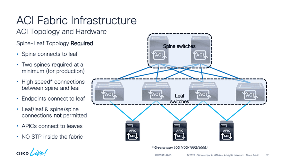
No direct connection between tier-1 leaf switches, tier-2 leaf switches, or spine switches is allowed. If you incorrectly cable spine switches to each other or leaf switches in the same tier to each other, the interfaces will be disabled.

Cisco ACI Fabric
Diagram: Cisco ACI Fabric. Source Cisco Live.


Video 2: Demonstration on a leaf and spine data center design

The following tutorial will examine the leaf and spine data center architecture. We know this design is a considerable step from traditional DC design. As a use case, we will focus on how Cisco has adopted the leaf and spine design with its Cisco ACI product. We will address the components and how they form the Cisco ACI fabric.

Spine and Leaf Design: Cisco ACI
Prev 1 of 1 Next
Prev 1 of 1 Next

BGP Route Reflection

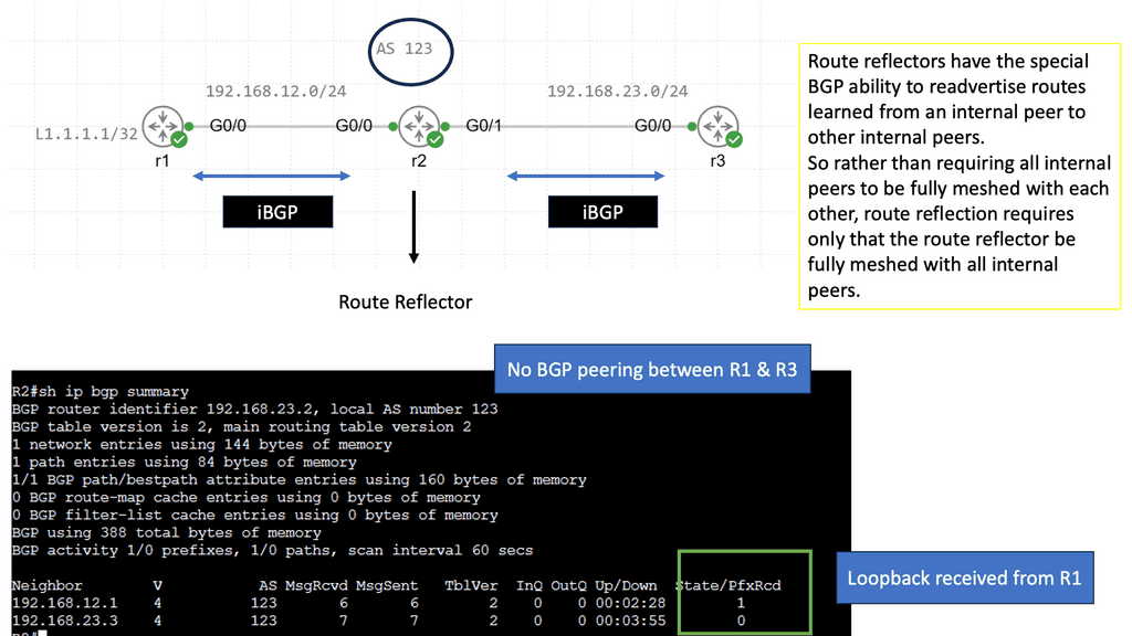
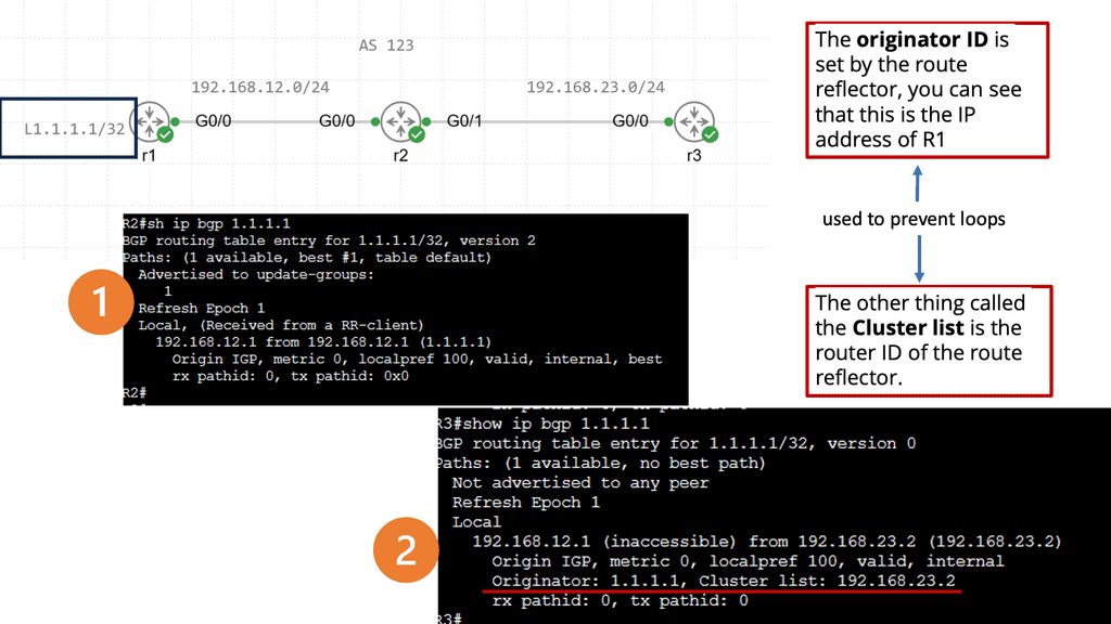
Under the cover, Cisco ACI works with BGP Route-Reflection. BGP Route Reflection creates a hierarchy of routers within the ACI fabric. At the top of the hierarchy is a Route-Reflector (RR), a central point for collecting routing information from other routers within the fabric. The RR then reflects this information to other routers, ensuring that every router in the network has a complete view of the routing table.

The ACI uses MP-BGP protocol to distribute external Network subnets or prefixes inside the ACI fabric. To create an MP-BGP route reflector, we must select two Spines acting as Route Reflectors and make an iBGP Neighbourship to all other Leafs.

BGP Route Reflection
Diagram: BGP Route Reflection

The ACI Cisco Architecture

The ACI Cisco operates with several standard ACI building blocks. These include Endpoint Groups (EPGs) that are used to classify and group similar workloads; then, we have the Bridge Domains (BD), VRFs, Contract constructs, COOP protocol in ACI, and micro-segmentation. With micro-segmentation in the ACI, you can get granular policy enforcement right the workload anywhere in the network.

Unlike in the traditional network design, you don’t need to place certain workloads in specific VLANs or, in some cases, physical locations. The ACI can incorporate devices separate from the ACI, such as a firewall, load balancer, or an IPS/IDS, for additional security mechanisms. This enables the dynamic service insertion of Layer 4 to Layer 7 services. Here, we have a lot of flexibility with the redirect option and service graphs.

Cisco ACI 

ACI network


Automation and consitency


Multi-cloud acceleration


Zero-trust security protectomn

Centralised management

Multi-site capabilities 

The ACI Infrastructure

The Cisco ACI architecture is optimized to learn endpoints dynamically with its dynamic endpoint learning functionality. So, we have endpoint learning in the data plane. Therefore, the other devices learn of the endpoints connected to that local leaf switch; the spines have a mapping database that saves many resources on the spine and can optimize the data traffic forwarding. So you don’t need to flood traffic anymore. If you want, you can turn off flooding in the ACI fabric. Then, we have an overlay network.

As you know, the ACI network has both an overlay and a physical underlay; this would be a virtual underlay in the case of Cisco Cloud ACI. The ACI uses VXLAN, the overlay protocol that rides on top of a simple leaf and spine topology, with standards-based protocols such as IS-IS and BGP for route propagation. 

Video: BGP in the Data Center

In this whiteboard session, we will address the basics of BGP. A network exists specifically to serve the connectivity requirements of applications, and these applications are to serve business needs. So these applications must run on stable networks, and stable networks are built from stable routing protocols.

Routing protocols are predefined rules used by the routers that interconnect your network to maintain communication between the source and the destination. These protocols help to find routes between two nodes on the computer network.

BGP in the Data Center
Prev 1 of 1 Next
Prev 1 of 1 Next

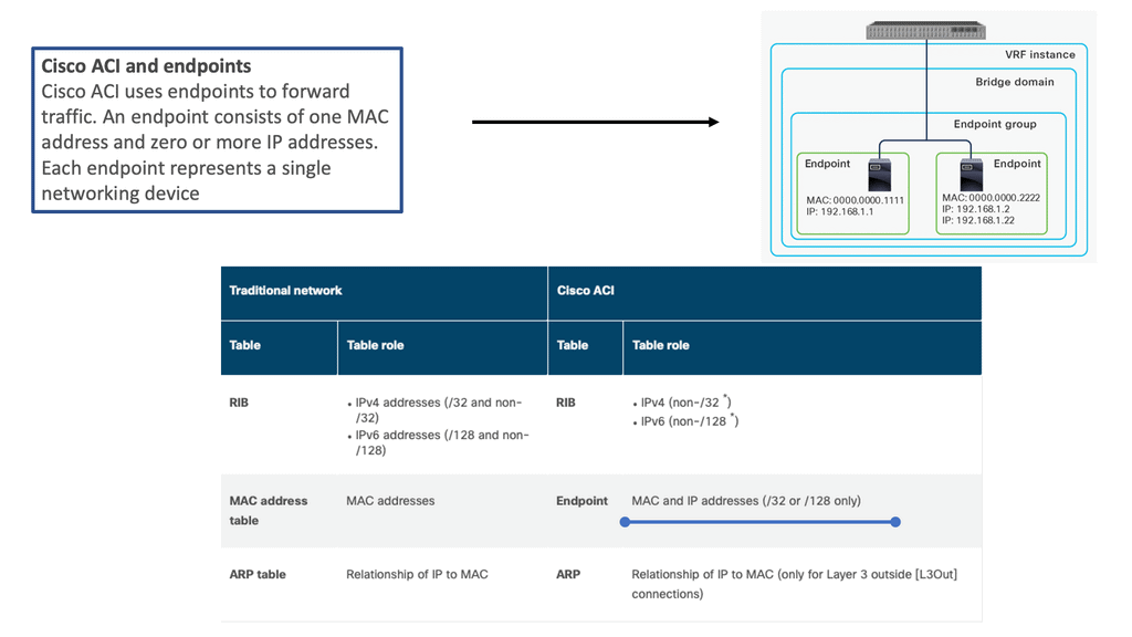
ACI Cisco and endpoints

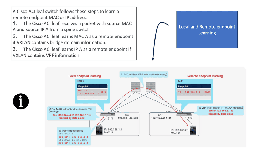
In a traditional network, three tables are used to maintain the network addresses of external devices: a MAC address table for Layer 2 forwarding, a Routing Information Base (RIB) for Layer 3 forwarding, and an ARP table for the combination of IP addresses and MAC addresses. Cisco ACI, however, maintains this information differently, as shown below.

ACI Endpoint learning
Diagram: Endpoint Learning. Source Cisco.com

What is ACI Endpoint Learning?

ACI endpoint learning refers to discovering and monitoring the network endpoints within an ACI fabric. Endpoints include devices, virtual machines, physical servers, users, and applications. Network administrators can make informed decisions regarding network policies, security, and traffic optimization by gaining insights into these endpoints’ location, characteristics, and behavior.

How Does ACI Endpoint Learning Work?

ACI fabric leverages a distributed, controller-based architecture to facilitate endpoint learning. When an endpoint is connected to the fabric, ACI utilizes a variety of mechanisms to gather information about it. These mechanisms include Address Resolution Protocol (ARP) snooping, Link Layer Discovery Protocol (LLDP), and even integration with hypervisor-based systems.

Once an endpoint is detected, ACI Fabric builds a comprehensive endpoint database called the Endpoint Group (EPG). This database contains vital information such as MAC addresses, IP addresses, VLANs, and associated policies. By continuously monitoring and updating this database, ACI ensures real-time visibility and control over the network endpoints.

Benefits of ACI Endpoint Learning:

1. Enhanced Security: With ACI endpoint learning, network administrators can enforce security policies by controlling traffic flow based on endpoint characteristics. Unauthorized or suspicious endpoints can be automatically detected and isolated, reducing the risk of data breaches and unauthorized access.

2. Simplified Network Operations: ACI’s endpoint learning eliminates the need for manual configuration of network policies and access control lists (ACLs). By dynamically learning the endpoints and their associated attributes, ACI enables automated policy enforcement, reducing human error and simplifying network management.

3. Efficient Traffic Optimization: ACI’s endpoint learning enables intelligent traffic steering by understanding the location and behavior of endpoints. This information allows for intelligent load balancing and traffic optimization, ensuring optimal performance and reducing congestion within the infrastructure.

Implementation Endpoint Learning Considerations:

To leverage the benefits of ACI endpoint learning, organizations need to consider a few key aspects:

1. Infrastructure Design: A well-designed ACI fabric with appropriate leaf and spine switches is crucial for efficient endpoint learning. Proper VLAN and subnet design should be implemented to ensure accurate endpoint identification and classification.

2. Endpoint Group (EPG) Definition: Defining and associating EPGs with appropriate policies is essential. EPGs help categorize endpoints based on their characteristics, allowing for granular policy enforcement and simplified management.

Diagram: ACI Endpoint Learning. The source is Cisco.


Forwarding Behavior. The COOP database

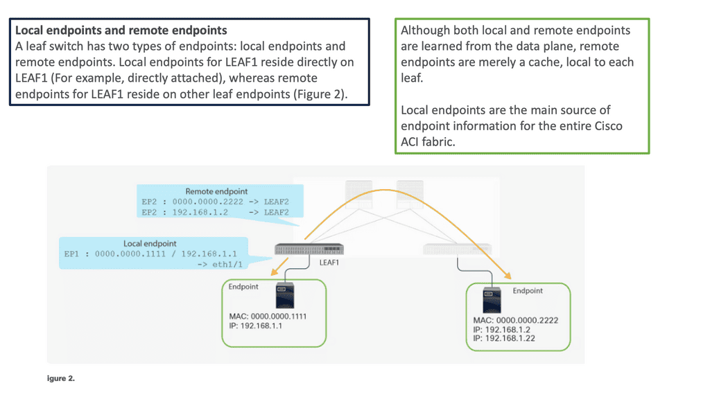
Local and remote endpoints are learned from the data plane, but remote endpoints are local caches. Cisco ACI’s fabric relies heavily on local endpoints for endpoint information. A leaf is responsible for reporting its local endpoints to the Council Of Oracle Protocol (COOP) database located on each spine switch, which implies that all endpoint information in the Cisco ACI fabric is stored there.

Each leaf does not need to know about all the remote endpoints to forward packets to the remote endpoints because this database is accessible. When a leaf does not know about a remote endpoint, it can still forward packets to spine switches. This forwarding behavior is called spine proxy.

Diagram: Endpoint Learning. The source is Cisco.

In a traditional network environment, switches rely on the Address Resolution Protocol (ARP) to map IP addresses to MAC addresses. However, this approach becomes inefficient as the network scales, resulting in increased network traffic and complexity. Cisco ACI addresses this challenge by utilizing local endpoint learning, a more intelligent and efficient method of mapping MAC addresses to IP addresses.

Diagram: Local and Remote endpoint learning. The source is Cisco.

ACI Cisco: The Main Features

We have a lot of changes right now that are impacting almost every aspect of IT. Applications are changing immensely, and we see their life cycles broken into smaller windows as the applications become less structured. In addition, containers and microservices are putting new requirements on the underlying infrastructure, such as the data centers they live in. This is one of the main reasons why a distributed system, including a data center, is better suited for this environment.

Distributed system/Intelligence at the edge

Like all networks, the Cisco ACI network still has a control and data plane. From the control and data plane perspective, the Cisco ACI architecture is still a distributed system. Each switch has intelligence and knows what it needs to do—one of the differences between ACI and traditional SDN approaches that try to centralize the control plane. If you try to centralize the control plan, you may hit scalability limits, not to mention a single point of failure and an avenue for bad actors to penetrate.

Cisco ACI Design
Diagram: Cisco ACI Design. Source Cisco Live.

MPLS overlay

In the following guide, we have an example of an MPLS overlay. Similar to that of Cisco ACI, an MPLS overlay pushes intelligence to the edge of the networks. MPLS overlay is a technique that enables the creation of virtual private networks (VPNs) over a shared IP infrastructure.

It involves encapsulating data packets with MPLS labels, allowing routers to forward traffic based on these labels rather than the traditional IP routing. This process enhances network efficiency, reduces complexity, and creates secure and isolated network segments.

Two PE nodes are running BGP, while the P nodes representing the core only run an IGP plus LDP. In the core, we have label switch paths that bring a lot of scalability.

MPLS overlay
Diagram: MPLS Overlay

Two large core devices

If we examine the traditional data center architecture, intelligence is often in two central devices. You could have two large core devices. What the network used to control and secure has changed dramatically with virtualization via hypervisors. We’re seeing faster change with containers and microservices being deployed more readily.

As a result, an overlay networking model is better suited. However, in a VXLAN overlay network, the intelligence is distributed across the leaf switch layer.

Therefore, distributed systems are better than centralized systems for more scale, resilience, and security. By distributing the Intelligence to the leaf layer, the scalability is not determined by the scalability of each leaf and is determined at a fabric level. However, there are scale limits on each device. Therefore, scalability as a whole is determined by the network design.

A key point: Overlay networking

The Cisco ACI architecture provides an integrated Layer 2 and 3 VXLAN-based overlay networking capability to offload network encapsulation processing from the compute nodes onto the top-of-rack or ACI leaf switches. This architecture provides the flexibility of software overlay networking in conjunction with the performance and operational benefits of hardware-based networking. We will have a lab guide on overlay networking in just a moment.

ACI infrastructure
Diagram: ACI infrastructure.

ACI Cisco New Concepts

Networking in the Cisco ACI architecture differs from what you may use in traditional network designs. It’s not different because we use an entirely new set of protocols. ACI uses standards-based protocols such as BGP, VXLAN, and IS-IS. However, the new networking constructs inside the ACI fabric exist only to support policy.

ACI has been referred to as stateless architecture. As a result, the network devices have no application-specific configuration until a policy is defined stating how that application or traffic should be treated on the network.

This is a new and essential concept to grasp. So, now, with the ACI, the network devices in the fabric have no application-specific configuration until there is a defined policy. No configuration is tied to a device. With a traditional configuration model, we have many designs on a device, even if it’s not being used. For example, we had ACL and QoS parameters configured, but nothing was using them.

  • Cisco ACI: Stateless Architecture.

  • ACI Network: Standards-based protocols such as BGP.

  • ACI Network: New ACI network constructs.

  • ACI Fabric Contructs: EPGs and Contracts.

  • Cisco ACI Architecture: VXLAN distributed architecture.

  • Cisco ACI Fabric: No policy tied to devices.

The APIC controller

The APICs, the management plan that defined the policy, do not need to push resources when nothing connected utilizes that. The APIC controller can see the entire fabric and has a holistic viewpoint.

Therefore, it can correlate configurations and integrate them with devices to help manage and maintain the security policy you define. We see every device on the fabric, physical or virtual, and can maintain policy consistency and, more importantly, recognize when policy needs to be enforced. 

APIC Controller
Diagram: APIC Controller. Source Cisco Live.

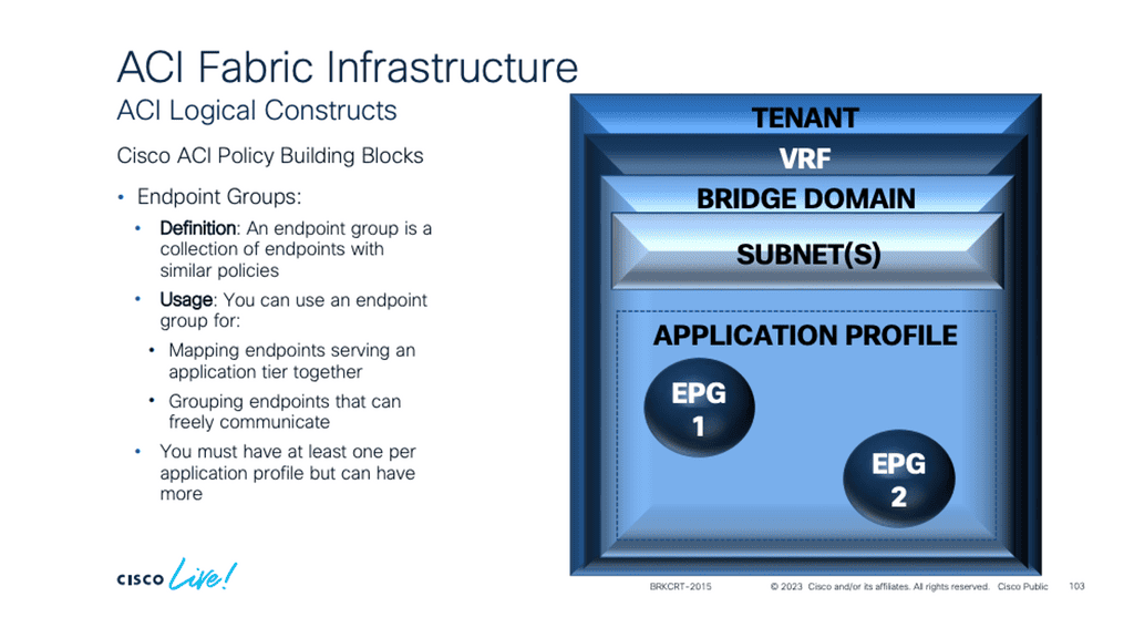
Endpoint groups (EPG)

We touched on this a moment ago. Groups or endpoint groups (EPGs) and contracts are core to the ACI. Because this is a zero-trust network by default, communication is blocked in hardware until a policy consisting of groups and contracts is defined. With Endpoint Groups, we can decouple and separate the physical or virtual workloads from the constraints of IP addresses and VLANs. 

So, we are grouping similar workloads into groups known as Endpoint Groups. Then, we can control group behavior by applying policy to the groups and not the endpoints in the group. As a security best practice, it is essential to group similar workloads with similar security sensitivity levels and then apply the policy to the endpoint group.

For example, a traditional data center network could have database and application servers in the same segment controlled by a VLAN with no intra-VLAN filtering. The EPG approach removes the barriers we have had with traditional networks with the limitation of the IP address being used as the identifier and locator and the VLANs restrictions.

This is a new way of thinking and allows devices to communicate with each other without having to change the IP address, VLAN, or subnet.

ACI Endpoint Groups
Diagram: ACI Endpoint Groups. Source Cisco Live.

EPG Communication

The EPG provides a better way to provide segmentation than the VLAN, which was never meant to live in a world of security. Anything in the group, by default, can communicate freely, and Inter-EPG communication needs a policy. This policy construct that ACI uses is called a contract. So, having similar workloads of similar security levels in the same EPG makes sense. All devices inside the same endpoint group can talk to each other freely.

This behavior can be modified with intra-EPG isolation, similar to a private VLAN where communication between group members is not allowed. Or, intra-EPG contracts can be used only to allow specific communications between devices in an EPG.

Endpoint groups
Diagram: Cisco Endpoint Groups (EPG).

Data Center Network Challenges

Let us examine well-known data center challenges and how the Cisco ACI network solves them.

Cisco Data Center

Cisco ACI 

Challenges

  • Complicated Topologies

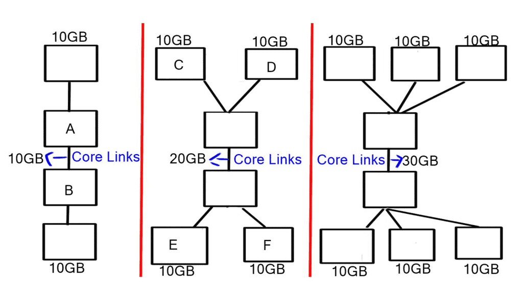
  • Oversubscription

  • Varying Bandwidths

  • Management Challenges

Cisco Data Center

Cisco ACI 

Challenges

  • Lack of Portability

  • Issues with ACL

  • Issues with Spanning Tree

  • Core-Distribution Designs

Complicated topologies

Usually, a traditional data center network design uses core distribution access layers. When you add more devices, this topology can be complicated to manage. Cisco ACI uses a simple spine-leaf topology wherein all the connections within the Cisco ACI fabric are from leaf-to-spine switches, and a mesh topology is between them. There is no leaf-to-leaf and no spine-to-spine connectivity.

How ACI Cisco overcomes this

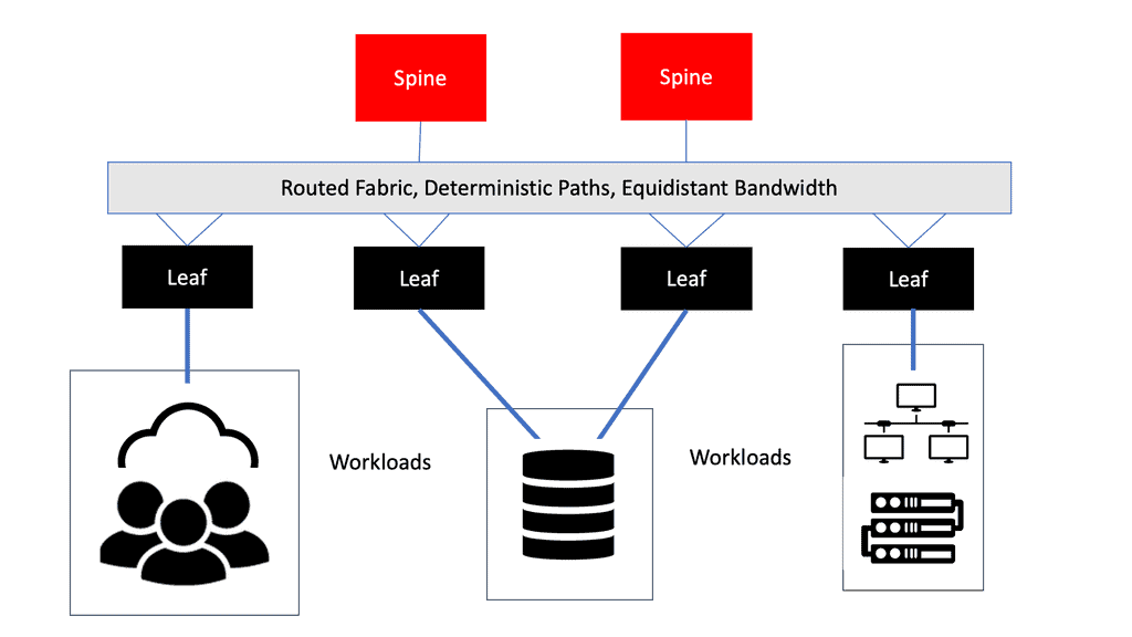
The Cisco ACI architecture uses the leaf-spine, consisting of a two-tier “fat tree” topology with equidistant bandwidths. The leaf layer connects to the physical and virtual workloads and network services. The spine layer is the transport layer that interconnects the leaves.

Oversubscription

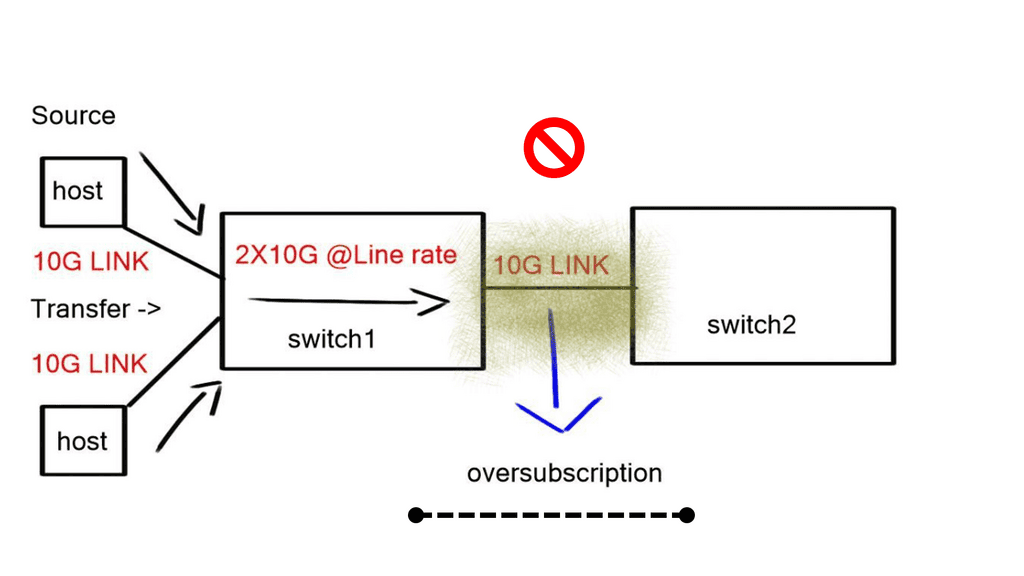
Oversubscription generally means potentially requiring more resources from a device, link, or component than are available. Therefore, the oversubscription ratio must be examined at multiple aggregation points in the design, including the line card to switch fabric bandwidth and the switch fabric input to uplink bandwidth.

Oversubscription Example

Let’s look at a typical 2-layer network topology with access switches and a central core switch. The access switches have 24 user ports and one uplink port. The uplink port is connected to the core switch. Each access switch has 24 1Gb user ports and a 10Gb uplink port. So, in theory, if all the user ports are transmitted to a server simultaneously, they would require 24 GB of bandwidth (24 x 1 GB).

However, the uplink port is only 10, limiting the maximum bandwidth to all the user ports. The uplink port is oversubscribed because the theoretical required bandwidth (24Gb) exceeds the available bandwidth (10Gb). Oversubscription is expressed as a ratio of bandwidth needed to available bandwidth. In this case, it’s 24Gb/10Gb or 2.

Varying bandwidths

We have layers of oversubscription with the traditional core, distribution, and access designs. We have oversubscription at the access, distribution, and core layers. The cause of this will give varying bandwidth to endpoints if they want to communicate with an endpoint that is near or an endpoint that is far away. With this approach, endpoints on the same switch will have more bandwidth than two endpoints communicating across the core layer.

Users and application owners don’t care about networks; they want to place their workload wherever the computer is and want the same BW regardless of where you place it. However, with traditional designs, the bandwidth available depends on where the endpoints are located.

How ACI Cisco overcomes this

The ACI leaf and spine have equidistant endpoints between any two endpoints. So if any two servers have the same bandwidths, which is a big plus for data center performance, then it doesn’t matter where you place the workload, which is a big plus for virtualized workloads. This gives you unlimited workload placement.

data center challenges
Diagram: Data center challenges.

Lack of portability

Applications are built on top of many building blocks. We use contracts such as VLANs, IP addresses, and ACLs to create connectivity. We use these constructs to create and translate the application requirements to the network infrastructure. These constructs are hardened into the network with configurations applied before connectivity.

These configurations are not very portable. It’s not that they were severely designed; they were never meant to be portable. Location Independent Separation Protocol (LISP) did an excellent job making them portable. However, they are hard-coded for a particular requirement at that time. Therefore, if we have the exact condition in a different data center location, we must reconfigure the IP address, VLANs, and ACLs. 

How ACI Cisco overcomes this

An application refers to a set of networking components that provides connectivity for a given set of workloads. These workloads’ relationship is what ACI calls an “application,” and the connection is expressed by what ACI calls an application network profile. With a Cisco ACI design, we can create what is known as Application Network Profiles (ANPs).

The ANP expresses the relationship between the application and its communications. It is a configuration template used to express the relationship between segments. The ACI then translates those relationships into networking constructs such as VLANs, VXLAN, VRF, and IP addresses that the devices in the network can then implement.

Issues with ACL

The traditional ACL is very tightly coupled with the network topology, and anything that is tightly coupled will kill agility. It is configured on a specific ingress and egress interface and pre-set to expect a particular traffic flow. These interfaces are usually at demarcation points in the network. However, many other points in the network could do so with security filtering.

How ACI Cisco overcomes this

The fundamental security architecture of the Cisco ACI design follows an allow-list model where we explicitly define what traffic should be permitted. A contract is a policy construct used to define communication between EPGs.  Without a contract between EPGs, no unicast communication is possible between those EPGs unless the VRF is configured in “unenforced” mode or those EPGs are in a preferred group.

A contract is not required to communicate between endpoints in the same EPG (although transmission can be prevented with intra-EPG isolation or intra-EPG contract). We have a different construct to apply the policy in ACI. We use the contract construct, and within the contract construct, we have subjects and filters that specify how endpoints are allowed to communicate.

These managed objects are not tied to the network’s topology because they are not applied to a specific interface. Instead, the contracts are used in the intersection between EPGs. They represent rules the network must enforce irrespective of where these endpoints are connected.   

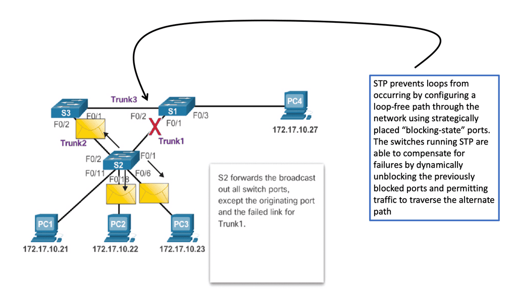
Issues with Spanning Tree Protocol (STP)

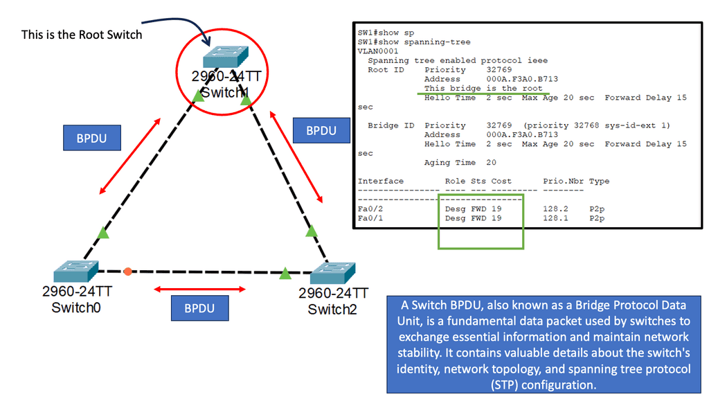
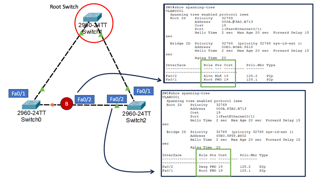
A significant shortcoming of STP is that it is a brittle failure mode that can bring down entire data centers or campus networks when something goes wrong. Though modifications and enhancements have addressed some of these risks, this has happened at the cost of technical debt in design and maintenance.

When you think about how this works, we have a BPDU that acts as a HELLO mechanism, and when we stop receiving the BPDUs and the link stays up, we decide to forward all the links. So, spanning Tree Protocol causes outages.

How ACI Cisco overcomes this

The Cisco ACI does not run Spanning Tree Protocol natively, meaning the ACI control plane does not run STP. Inside the fabric, we are running IS-IS as the interior routing protocol. If we stop receiving, we don’t go into an all-forwarding state with IS-IS. As we have IP reachability between Leaf and Spine, we don’t have to block ports and see actual traffic flows that are not the same as the physical topology.

So, within the ACI fabric, we have all the advantages of layer three networks, which are more robust and predictable than we have with an STP design. With ACI, we don’t rely on SPT for the topology design. Instead, the ACI uses ECMP for layer 2 and Layer 3 forwarding. We can use ECMP because we have routed links between the leaves and spines in the ACI fabric. So, the ACI has ECMP for Layer 2 and Layer 3 forwarding.

leaf and spine design
Diagram: Leaf and spine design.

Core-distribution design

The traditional design uses VLANs to logically segment Layer 2 boundaries and broadcast domains. VLANs use network links inefficiently, resulting in rigid device placement. We also have a cap on the number of VLANs we can create. Some applications require that you need Layer 2 adjacencies.

For example, clustering software requires Layer 2 adjacency between source and destination servers. However, if we are routing at the access layer, only servers connected to the same access switch with the same VLANs trunked down would be Layer 2-adjacent. 

How ACI Cisco overcomes this

VXLAN solves this dilemma in ACI by decoupling Layer 2 domains from the underlying Layer 3 network infrastructure. With ACI, we are using the concepts of overlays to provide this abstract. Isolated Layer 2 domains can be connected over a Layer 3 network using VXLAN. Packets are transported across the fabric using Layer 3 routing.

This paradigm fully supports layer 2 networks. Large layer-2 domains will always be needed, for example, for VM mobility, clusters that don’t or can’t use dynamic DNS and non-IP traffic, and broadcast-based intra-subnet communication.

Cisco ACI Architecture: Leaf and Spine

The fabric is symmetric with a leaf and spine design, and we have central bandwidth. Therefore, regardless of where a device is connected to the fabric, it has the same bandwidth as every other device connected to the same fabric. This removes the placement restrictions that we have with traditional data center designs. A spine-leaf architecture is a data center network topology that consists of two switching layers—a spine and a leaf.

The leaf layer comprises access switches that aggregate server traffic and connect directly to the spine or network core. Spine switches interconnect all leaf switches in a full-mesh topology.

With low latency east-west traffic, optimized traffic flows are imperative for performance, especially for time-sensitive or data-intensive applications. A spine-leaf architecture aids this by ensuring traffic is always the same number of hops from its next destination, so latency is lower and predictable.

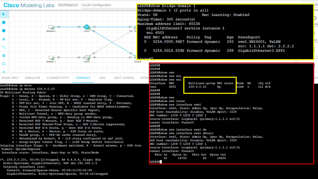
Displaying a VXLAN tunnel 

We have expanded the original design and added VXLAN. We are creating a Layer 2 network, or, more specifically, a Layer 2 overlay over a Layer 3 routed core. The Layer 2 extension allows the two hosts, desktop 0 and desktop 1, to communicate over the Layer 2 overlay that VXLAN creates.

The IP addresses of the hosts are 10.0.0.1 and 10.0.0.2 and are not reachable via the Leaf switches. The leaf switches cannot ping these. Consider the Leaf and the Spine switches a standard Layer 3 WAN or network for this lab. So we have unicast connectivity over the WAN.

The only IP routing addition I have added is the new loopback addresses on Leaf 1 and 2, of 1.1.1.1/32 and 2.2.2.2/32, used for ingress replication for VXLAN. Remember that the ACI is one of many products that use Layer 2 overlays. VXLAN can be used as a Layer 2 DCI. For a lab guide displaying Multicast VXLAN, go to this blogWhat is VXLAN

VXLAN overlay
Diagram: VXLAN Overlay

Notice below I am running a ping from desktop 0 to the corresponding desktop. These hosts are in the 10.0.0.0/8 range, and the core does not know these subnets. I’m also running a packet capture on the link Gi1 connected to Leaf A.

Notice the source and destination are 1.1.1.1 and 2.2.2.2.2, which are the VTEPs, and the IMCP traffic is encapsulated into UDP port 1024. The UDP port 1024 is explicitly set in the confirmation as the VXLAN port to use.

VXLAN unicast mode

ACI Network: VXLAN transport network

In a leaf-spine ACI fabric, We have a native Layer 3 IP fabric that supports equal-cost multi-path (ECMP) routing between any two endpoints in the network—using VXLAN as the overlay protocol allows any workload to exist anywhere in the network.

We can have physical and virtual machines in the same logical layer 2 domain while running layer 3 routing to the top of each rack. So we can have several endpoints connected to each leaf, and for one endpoint to communicate with another endpoint, we use VXLAN.

So, the transport of the ACI fabric is carried out with VXLAN. The ACI encapsulates traffic with VXLAN and forwards the data traffic across the fabric. Any policy that needs to be implemented gets applied at the leaf layer. All traffic on the fabric is encapsulated with VXLAN. This allows us to support standard bridging and routing semantics without the standard location constraints.

Diagram: VXLAN operations. The source is Cisco.
  • A key point – Video 3: Demonstration on overlay networking with VXLAN

The following video gives a deep dive into the operations of VXLAN—the VLAN tag field defined in 1. IEEE 802.1Q has 12 bits for host identification, supporting a maximum of only 4094 VLANs. It’s common these days to have a multi-tiered application deployment where every tier requires its segment, and with literally thousands of multi-tier application segments, this will run out.

Then came along the Virtual extensible local area network (VXLAN). VXLAN uses a 24-bit network segment ID, called a VXLAN network identifier (VNI), for identification. This is much larger than the 12 bits used for traditional VLAN identification.

Technology Brief : VXLAN – Introducing VXLAN
Prev 1 of 1 Next
Prev 1 of 1 Next

Council of Oracle Protocol

COOP protocol in ACI and the ACI fabric

The fabric appears to the outside as one switch capable of forwarding Layers 2 and 3. In addition, the fabric is a Layer 3 network routed network and enables all links to be active, providing ECMP forwarding in the fabric for both Layer 2 and Layer 3. Inside the fabric, we have routing protocols such as BGP; we also use Intermediate System-to-Intermediate System Protocol (IS-IS) and Council of Oracle Protocol (COOP) for all forwarding endpoint-to-endpoint communications.

The COOP protocol in ACI communicates the mapping information (location and identity) to the spine proxy. A leaf switch forwards endpoint address information to the spine switch ‘Oracle’ using Zero Message Queue (ZMQ). The COOP protocol in ACI is something new to data centers. The Leaf switches use COOP to report local station information to the Spine (Oracle) switches.

COOP protocol in ACI

Let’s look at an example of how the COOP protocol in ACI works. We have a Leaf that learns of a host. The Leaf reports this information; let’s say it knows Host B and sends this to one of the Spine switches chosen randomly using the Council Of Oracle Protocol.

The Spine switch then relays this information to all the other Spines in the ACI fabric so that every Spine has a complete record of every single endpoint. The Spines switches record the information learned via the COOP in the Global Proxy Table, which resolves unknown destination MAC/IP addresses when traffic is sent to the Proxy address.

Lab guide on the COOP database.

So, we know that the Spine has a COOP database of all endpoints in the fabric. Council of Oracle Protocol (COOP) is used to communicate the mapping information (location and identity) to the spine proxy. A leaf switch forwards endpoint address information to the spine switch ‘Oracle’ using Zero Message Queue (ZMQ).

The command: Show coop internal info repo key allows us to verify that the endpoint is in the COOP database using the BD VNID of 16154554 mapped to the MAC address of 0050.5690.3eeb. With this command, you can also see the tunnel next hop and IPv4 and IPv6 addresses tied to this MAC address.

coop protocol in ACI
Diagram: COOP protocol in ACI

The fabric constructs

The ACI Fabric contains several new network constructs specific to ACI that enable us to abstract much of the complexity we had with traditional data center designs. These new concepts are ACI’s Endpoint Groups, Contracts, Bridge Domains, and COOP protocol.

In addition, we have a distributed Layer 3 Anycast gateway function that ensures optimal Layer 3 and Layer 2 forwarding. We also have original constructs you may have used, such as VRFs. The layer 3 anycast feature is popular and allows flexible placement of the default gateway suited for designs that need to be agile.

Extending the ACI Fabric

Developing the Cisco ACI architecture

I have always found extending data risky when undergoing data center network design projects. However, the Cisco ACI architecture can be extended without the traditional Layer 2 and 3 Data Center Interconnect (DCI) mechanisms. Here, we can use Multi-Pod and Multi-Site and better control large environments that need to span multiple locations and for applications to share those multiple locations in active-active application deployments.

Diagram: Extending the ACI fabric. Source is Cisco

When considering data center designs, terms such as active-active and active-passive are often discussed. In addition, enterprises are generally looking for data center solutions that provide geographical redundancy for their applications.

Enterprises also need to be able to place workloads in any data center where computing capacity exists—and they often need to distribute members of the same cluster across multiple data center locations to provide continuous availability in the event of a data center failure. The ACI gives us options for extending the fabric to multiple locations and location types.

For example, there are stretched fabric, multi-pod, multi-site designs, and, more recently, Cisco Cloud ACI.

Cisco ACI Design
Diagram: Cisco ACI design: Extending the network.

ACI design: Multi pod

The ACI Multi-Pod is the next evolution of the original stretch fabric design we discussed. The architecture consists of multiple ACI Pods connected by an IP Inter-Pod Layer 3 network. With the stretched fabric, we have one Pod across several locations. Cisco ACI MultiPod is part of the “single APIC cluster/single domain” family of solutions; a single APIC cluster is deployed to manage all the interconnected ACI networks.

These ACI networks are called “pods,” Each looks like a regular two-tier spine-leaf topology. The same APIC cluster can manage several pods.  All of the nodes deployed across the individual pods are under the control of the same APIC cluster. The separate pods are managed as if they were logically a single entity. This gives you operational simplicity. We also have a fault-tolerant fabric since each Pod has isolated control plane protocols.

Diagram: Multi-pod. Source is Cisco

ACI design: Cisco cloud ACI

Cisco Cloud APIC is an essential new solution component introduced in the architecture of Cisco Cloud ACI. It plays the equivalent of APIC for a cloud site. Like the APIC for on-premises Cisco ACI sites, Cloud APIC manages network policies for the cloud site it runs on by using the Cisco ACI network policy model to describe the policy intent.

ACI design: Multisite

ACI Multi-Site enables you to interconnect separate APIC cluster domains or fabric, each representing a separate availability zone. As a result, we have separate and independent APIC domains and fabrics. This way, we can manage multiple fabrics as regions or availability zones. ACI Multi-Site is the easiest DCI solution in the industry. Communication between endpoints in separate sites (Layers 2 and 3) is enabled simply by creating and pushing a contract between the endpoints’ EPGs.

Cisco ACI Architecture

ACI Network

Cisco ACI 

  • Leaf and Spine

  • Equidistant endpoints

  • ACI APIC Controller

  • Multi-Pod and Multi-Site

  • VXLAN Overlay

  • Endpoint Groups

  • Bridge Domains

  • VRFs

  • Automation and Consitency

  • Multi-cloud support

  • Zero Trust Security 

  • Central Management


leaf and spine design

Spine Leaf Architecture

Spine Leaf Architecture

In today's interconnected world, where data traffic is growing exponentially, having a robust and scalable network architecture is crucial for businesses and organizations. One such architecture that has gained popularity in recent years is the Spine Leaf architecture. This blog post will explore Spine Leaf architecture, its benefits, and how it can revolutionize network design.

Spine Leaf architecture, also known as Clos architecture, is a network design approach that offers high bandwidth, low latency, and scalability. It is commonly used in data centers and large-scale enterprise networks. The architecture is based on a two-tier design consisting of spine switches and leaf switches.

Table of Contents

Highlights: Leaf and Spine

Data center topology

A spine-leaf architecture is a variation of data center topologies that consists of two switching layers. We have a spine-leaf switch design consisting of two layers. The leaf layer consists of access switches that aggregate traffic from endpoints that could be traditional servers or containers and connect directly to the spine, which is the network core. The Spine switch will often have two for redundancy to interconnect all leaf switches in a full-mesh leaf and spine topology. With a spine and leaf data center network design, the leaf switches do not directly connect.

Example: Cisco ACI

Instead, all connectivity goes through the core, and the physical and logical layout is generally the same based on network overlay protocols, more than likely VXLAN. An example of a data center that utilizes such a design is the Cisco ACI. The ACI Cisco consists of three main components: the Application Policy Infrastructure Controller (APIC), the spine switches, and the leaf switches.


Spine Leaf Architecture

Key Spine Leaf Architecture Discussion Points:


  • Introduction to the spine leaf architecture and what is involved.

  • Highlighting the details of this type of data center design.

  • Critical points on spine-leaf switch requirements.

  • Technical details on the origins of this design.

  • Technical solutions that can be used in the leaf and spine design.


Back to Basics: Data center design

At its most straightforward, a data center is a physical facility that houses applications and data. Such a design is based on a computing and storage resources network that enables the delivery of shared applications and data. The critical elements of a data center design include routers, switches, firewalls, storage systems, servers, and application-delivery controllers.

The data center should be flexible in quickly deploying and supporting new services. Such a design needs substantial initial planning and consideration of port density, access layer uplink bandwidth, actual server capacity, and oversubscription, to name a few.

Traditional Tree-Based Topologies

We have tree-based topologies on the opposite side of a spine-leaf switch design. Tree-based topologies have been the mainstay of data center networks. Traditionally, Cisco has recommended a multi-tier tree-based data center topology, as depicted in the diagram below.

These networks are characterized by aggregation pairs ( AGGs ) that aggregate through many network points. Hosts connect to access or edge switches, which connect to distribution, and distribution connects to the core.

The core should offer no services ( firewall, load balancing, or WAAS ), and its central role is to forward packets as quickly as possible. The aggregation switches define the boundary for the Layer 2 domain, and to contain broadcast traffic to individual domains, VLANs are used to further subdivide traffic into segmented groups. A style of design that operates very differently from that of a spine-leaf architecture.
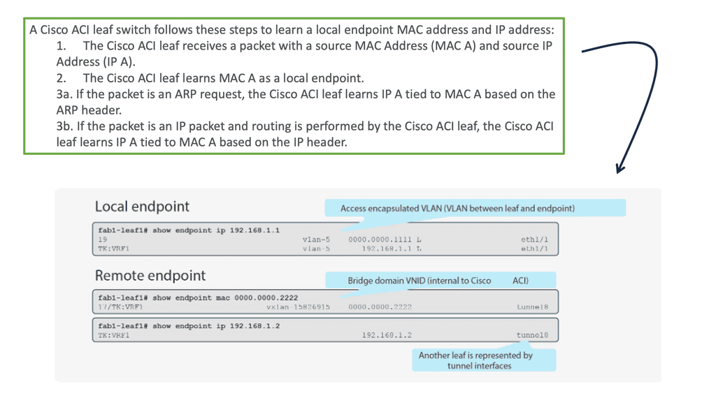
 

Lab guide: Leaf and Spine with Cisco ACI 

The following lab guide addresses the leaf and spine with Cisco ACI. The screenshot below shows a small topology that is fine for demonstration purposes. The leaf and spine are based on the Cisco Nexus 9000 series. The ACI has an automated fabric discovery process, and as you can see, we have all fabric members successfully registered.

SDN data center
Diagram: Cisco ACI fabric checking.

The traditional three-tier model was based on the following design principles:

  1. The access switch connects to endpoints, e.g., servers.
  2. The aggregation or distribution switches provide redundant connections to access switches.
  3. The core switches provide fast transport between aggregation switches, typically connected in a redundant pair for high availability.
  4. Networking and security services such as load balancing or firewalling were typically connected to the distribution layers.
spine leaf architecture
The traditional data center design. Non spine-leaf architecture.

The focus of the design

Their design’s focus was based on fault avoidance principles, and the strategy for implementing this principle is to take each switch and its connected links and build redundancy into it. This led to the introduction of port channels and devices deployed in pairs. In addition, servers pointed to a First Hop Redundancy Protocol, like HSRP or VRRP ( Hot Standby Router Protocol or Virtual Router Redundancy Protocol ). Unfortunately, the steady-state type of network design led to many inefficiencies:

  1. Inefficient use of bandwidth via a single-rooted core.
  2. Operational and configuration complexity.
  3. The cost of having redundant hardware.
  4. It is not optimized for small flows.

Recent changes to application and user requirements have changed the functions of data centers, which in turn has altered the topology and design of the data center to a spine-leaf switch topology. For example, the traditional aggregation point design style was inefficient, and recent changes in end-user requirements are driving architects to design around the following key elements.

Spine Leaf Architecture: Requirements

A spine-leaf architecture collapses one of these tiers at the most basic level, as depicted in the diagram below. Follow the following design principles:

  1. The removal of the Spanning Tree Protocol (STP)
  2. Increased use of fixed-port switches over modular models for the network backbone
  3. More cabling to purchase and manage, given the higher interconnection count
  4. A scale-out vs. scale-up of infrastructure.
what is spine and leaf architecture
Diagram: What is spine and leaf architecture? 2-Tier Spine Leaf Design

Leaf and Spine Main Points

With the introduction of the cloud and containerized infrastructure, there was an increase in east-west traffic. East-west traffic differs from north to south traffic and moves laterally from server to server. Generally, this type of traffic flow stays internal to the data center.

With the change in traffic patterns, we must design our data centers to have low-latency and optimized traffic flows, especially for time-sensitive or data-intensive applications. A spine-leaf data center design aids this by ensuring traffic always has the same number of hops from its next destination, so latency is lower and predictable.
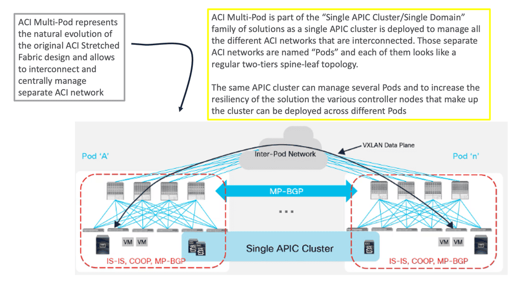
STP has always been problematic in the data center. Now, the capacity improves with a leaf and spine because STP is no longer required. In the past, STP blocked redundant paths between two switches, where only one could be active at any time.
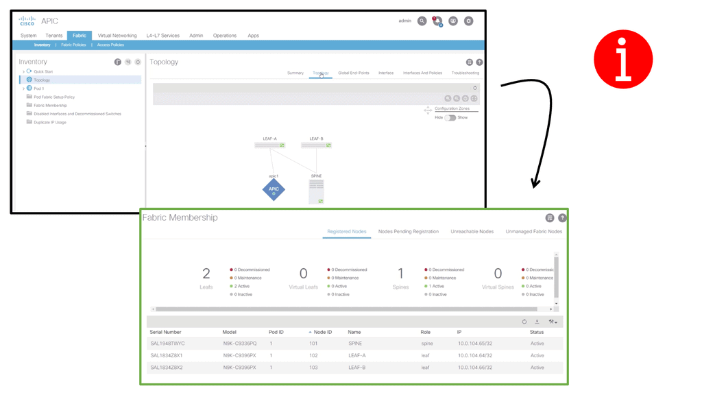
As a result, paths often need to be more subscribed. With a leaf, spine-leaf architectures rely on protocols such as Equal-Cost Multipath (ECPM) routing to load balance traffic across all available paths while still preventing network loops. So, instead of running STP to the spine layer, we can run routing protocols.
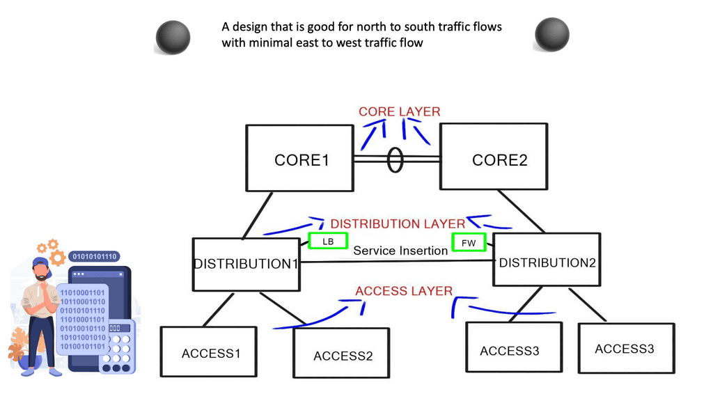
We also have better scalability. We can add additional spine switches, and leaf switches can be seamlessly inserted when port density becomes problematic. There is no need to take down the core layer for upgrades.

STP Blocking.
Diagram: STP Blocking. Source Cisco Press free chapter.

Data Center Requirements

  • 1) Equidistant endpoints with non-blocking network core.

Equidistant endpoints mean that every device is a maximum of one hop away from the other, resulting in consistent latency in the data center. The term “non-blocking” refers to the internal forwarding performance of the switch.

Non-blocking is the ability to forward at line rate tx/Rx – sender X can send to receiver Y and not be blocked by a simultaneous sender. A blocking architecture cannot deliver the total bandwidth even if the individually switching modules are not oversubscribed or if all ports are not transmitting simultaneously.

  • 2) Unlimited workload placement and mobility.

The application team wants to place the application at any point in the network and communicate with existing services like storage. This usually means that VLANs need to sprawl for VMotion to work. The main question is, where do we need large layer 2 domains? Bridging doesn’t scale, and that’s not just because of spanning tree issues; it’s because the MAC addresses are not hierarchical and cannot be summarized. There is also a limit of 4000 VLANs.

  • 3) Lossless transport for storage and other elephant flows.

To support this type of traffic, data centers require not only conventional QoS tools but also Data Center Bridging ( DCB ) tools such as Priority flow control ( PFC ), Enhanced transmission selection ( ETS ), and Data Center Bridging Exchange ( DCBX ) to be applied throughout their designs. These standards are enhancements that allow lossless transport and congestion notification over full-duplex 10 Gigabit Ethernet networks.

Feature

 Benefit

Priority-based Flow Control ( PFC )

Manages bursty single traffic source on a multiprotocol link

Enhanced transmission selection ( ETS )

Enables bandwidth management between traffic types for multiprotocol links

Congestion notification

Addresses the problems of sustained congestion by moving corrective action to the edge of the network

Data Center Bridging Exchange Protocol 

Allows the exchange of enhanced Ethernet parameters

  • 4) Simplified provisioning and management.

Simplified provisioning and management are critical to operational efficiency. However, the ability to auto-provision and for the users to manage their networks is challenging for future networks.

  • 5) High server-to-access layer transmission rate at Gigabit and 10 Gigabit Ethernet.

Before the advent of virtualization, servers transitioned from 100Mbps to 1GbE as processor performance increased. With the introduction of high-performance multicore processors and each physical server hosting multiple VMs, the processor-to-network connection bandwidth requirements increased dramatically, making 10 Gigabit Ethernet the most common network access option for servers.

In addition, the popularization of 10 Gigabit Ethernet for server access has provided a straightforward approach to group/bundle multiple Gigabit Ethernet interfaces into a single connection, making Ethernet an extremely viable technology for future-proof I/O consolidation.

In addition, to reduce networking costs, data centers are now carrying data and storage traffic over Ethernet using protocols such as iSCSI ( Internet Small Computer System Interface ) and FCoE ( Fibre Channel over Ethernet ). FCoE allows the transport of Fibre channels over a lossless Ethernet network.

spine-leaf switch
FCoE Frame Format

Although there has been some talk of introducing 25 Gigabit Ethernet due to the excessive price of 40 Gigabit Ethernet, the two main speeds on the market are Gigabit and 10 Gigabit Ethernet. The following is a comparison table between Gigabit and 10 Gigabit Ethernet:

Gigabit Ethernet

 10 Gigabit Ethernet

+ Well know and field-tested

+ Much faster vMotion

+ Standard and cheap Copper cabling

+ Converged storage & network ( FCoE or lossless iSCSI/NFS)

+ NIC on the motherboard

+ Reduce the number of NICs per server

+ Cedric Kelly

+ Built-in Qos with ETS and PFC

+ Uses fiber cabling which has lower energy consumption and error rate

– Numerous NICs per hypervisor host. Maybe up to 6 NICs ( user data, VMotion, storage )

– More expensive NIC cards

– No storage/networking convergence. Unable to combine networking and storage onto one NIC

– Usually requires new cabling to be laid which intern could mean more structured panels

– No lossless transport for storage and elephant flows

– SFP used either for single-mode or multimode fiber can be up to $4000 list per each


Spine-Leaf Switch Design

The critical difference between traditional aggregation layers/points and fabric networks is that fabric doesn’t aggregate. If we want to provide 10GB for every edge router to send 10GB to every other edge router, we must add bandwidth between routers A and B, i.e., if we have three hosts sending at 10GB each, we need a core that supports 30 GB.

We must add bandwidth at the core because what if two routers wanted to send 2 x 10GB of data, and the core only supports a maximum of 10GB ( 10GB link between routers A and B)? Both data streams must be interleaved onto the oversubscribed link so that both senders get equal bandwidth. 

You get blocking and oversubscription when more bandwidth comes into the core than the core can accommodate. Blocking and oversubscription cause delay and jitter, which is bad for some applications, so we must find a way to provide total bandwidth between each end host.

Oversubscription is expressed as the ratio of inputs to outputs (ex. 3:1) or as a percent that is calculated (1 – (# outputs / # inputs)). For example, (1 – (1 output / 3 inputs)) = 67% oversubscribed). There will always be some oversubscription on the network, and there is nothing we can do to get away from that, but as a general rule of thumb, an oversubscription value of 3:1 is best practice.

Some applications will operate fine when oversubscription occurs. It is up to the architect to thoroughly understand application traffic patterns, bursting needs, and baseline states to define the oversubscription limits a system can tolerate accurately.

The simplest solution to overcome the oversubscription and blocking problems would be to increase the bandwidth between Router A and B, as shown in the diagram labeled “Traditional Aggregation Topology.” This is feasible up to a certain point. Router A and B links must also grow to 10GB and 30 GB when the number of edge hosts grows. Datacenter links and the optics used to connect them are expensive.

The Solution

Spine-Leaf Switch Design

The solution is to divide the core devices into several spine devices, which expose the internal fabric, enabling a spine-leaf architecture similar to what you see with ACI networks. This is achieved by spreading the fabric across multiple devices ( leaf and spine ).

The spreading of the fabric results in every leaf edge switch connecting to every spine core switch, resulting in every edge device having the total bandwidth of the fabric. This places multiple traffic streams parallel, unlike the traditional multitier design that stacks multiple streams onto a single link.

In addition, the higher degree of equal-cost multi-path routing ( ECMP ) found with leaf and spine architectures allows for greater cross-sectional bandwidth between layers, thus greater east-west bandwidth. There is also a reduction in the fault domain compared to traditional access, distribution, and core designs.

A failure of a single device only reduces the available bandwidth by a fraction, and only transit traffic will be lost with a link failure. ECMP reduces liability to a single fault and brings domain optimization.

Origination of the spine and leaf design

Charles Clos initially designed a Clos network in 1952 as a multi-stage circuit-switched interconnection network to provide a scalable approach to building large-scale voice switches. It constrained high-speed switching fabrics and required low-latency, non-blocking switching elements.

There has been an increase in the deployment of Clos-based models in data center deployments. Usually, the Clos network is folded around the middle to form a “folded-Clos” network, referred to as a spine-leaf architecture. The spine-leaf switch design consists of three switches:

  • Servers connect directly to ToR ( top of rack ) switches.
  • ToR connects to aggregation switches.
  • Intermediate switches connect to aggregation switches. 

The spine is responsible for interconnecting all Leafs and allows hosts in one rack to talk to hosts in another. The leaves are responsible for physically connecting the servers and distributing traffic via ECMP across all spines nodes.

Leaf and Spine: Folded 3-Stage Clos fabric

Spine-leaf switch deployment considerations:

A. Spine-leaf switch: Fixed or modular switches

Fixed Switches

Modular switches

+ Cheaper

+ Gradual Growth

+ Lower Power Consumption

 + Larger fabrics with leaf/spine topologies

+ Require less space

 + Build-in redundancy with redundant SUPs and SSO/NSF

+ More ports per RU

+ In-Service software redundancy

+ Easier to manage

– Hard to manage

– More expensive

– Difficult to expand

– More cabling due to an increase in device numbers

The leaf layer determines the size of the spine and the oversubscription ratios. It is responsible for advertising subnets into the network fabric. An example of a leaf device would be a Nexus 3064, which provides the following:

  1. Line rate for Layer 2 and Layer 3 on all ports.
  2. Shared memory buffer space.
  3. Throughput of 1/2 terabits per second ( Tbps ) and 950 million packets per second ( Mpps )
  4. 64-way ECMP

The spine layer is responsible for learning infrastructure routes and physically interconnecting all leaf nodes. The Nexus 7K is the platform for the Spine device layer. The F2 series line cards can provide 48x 10G line rate ports and fit the requirements for spine architecture very well.
The following are the types of implementations you could have with this topology:

  1. Layer 3 fabric with standard routing.
  2. Large-scale bridging ( FabricPath, THRILL, or SPB ).
  3. Many-chassis MLAG ( Cisco VSS ).

This article will focus on Layer 3 fabrics with standard routing.

B. Spine-leaf switch: Non-redundant layer 3 design

Spine-leaf switch: Design Summary

  1. Layer 3 directly to the access layer. Layer 2 VLANs do not span the spine layer.
  2. Servers are connected to single switches. Servers are not dual connected to two switches, i.e., there is no server to switch redundancy or MLAG.
  3. All connections between the switches will be pure routed point-to-point layer 3 links.
  4. There are no inter-switch VLANs, so no VLAN will ever go beyond one switch.

When the spine switches only advertise the default to the leaf switches, the leaf switches lose visibility of the entire network, and you will need additional intra-spine links. Therefore, intra-spine links should not be used for data plane traffic in a leaf-spine architecture.

Spine-leaf switch: Design assumptions

The spine layer passes a default route to the Leaf. The link between the Leaf connecting to Host 1 and Spine Z fails. In the diagram, the link is marked with a red “X.” Host 4 sends traffic to the fabric destined for Host 1.

This traffic spreads ( ECMP ) across all links connecting the connected Leaf to the Spine layers. The traffic hits Spine C, and as C does not have a direct link ( it has failed ) to the Leaf connecting to Host 1, some traffic may be dropped while others will be sub-optimal. To overcome this, you must add inter-switch links between the Spine layers, which is not recommended.

Video: Spine and Leaf design with Cisco ACI.

The following video will address fabric deployment and provisioning in the CISCO ACI. All of this is done automatically for you, and we will check to ensure this has been done for you. The Cisco ACI operates over a leaf and spine architecture.

We will confirm this by checking the individual ports on each ACI node, LLD status, and IS-IS adjacency status. We will also examine the traditional DC design based on the 3-tier architecture with many drawbacks, forcing us to move to a leaf and spine data center design.

Checking the Cisco ACI Fabric
Prev 1 of 1 Next
Prev 1 of 1 Next

Spine-leaf switch: Recommendations

  1. Buy Leaf switches that can support enough IP prefixes and don’t use summarization from Spine to Leaf.
  2. Always use 40G links instead of channels of 4 x 10G links because link aggregation bandwidth does not affect routing costs. If you lose a link in the port channel, the cost of the port channel does not change, which could result in congestion on the link. You could use Embedded Event Manager ( EEM ) scripting to change the OSPF cost after one of the port channels fails. This would add complexity to the network as you now don’t have equal-cost routes. This would lead you to use the Cisco proprietary protocol EIGRP, which supports unequal cost routing. If you didn’t want to support a Cisco proprietary protocol, you could implement MPLS TE between the ToR switches. First, you need to check that the DC switches support the MPLS switching of labels.
  3. Use QSFP optics as they are more robust than SFP optics. This will lower the likelihood of one of the parallel links failing.


C. Spine-leaf switch: Redundant layer 3 design

Spine-leaf switch: Design Summary

  1. The servers are dual home to two different switches.
  2. Servers have one IP address due to the restriction of TCP applications. Ideally, use LACP ( Link Aggregation Control Protocol ) between the host and servers.
  3. Layer 2 trunk links between the Leaf switches are needed to carry VLANs that span both switches. This will restrict VLANs from spanning the core, thus creating a sizeable L2 fabric based on STP.
  4. ToR switches must be in the same subnets ( share the server’s subnet) and advertise this subnet into the fabric. Again, the servers are dual-homed to 2 switches with one IP address.

Spine-leaf switch: The challenges

The leaf switches both advertise the same subnet to the spine switches. The spine switches and thinks they have two paths to reach the host. The Spine switch will spread its traffic from Host 1 to Leaf switches connecting Host 1 and Host 2. In specific scenarios, this could result in traffic to the hosts traversing the Interswitch link between the leaf nodes. This may not be a problem if most traffic leaves the servers northbound ( traffic leaving the data center ). However, if there is a lot of inbound traffic, this link could become a bottleneck and congestion point. This may not be an issue if this is a hosting web server farm because most traffic will leave the data center to external users.

Spine-leaf switch: Recommendation

  1. If there is a lot of east-to-west traffic ( 80 % ), using LAG ( Link Aggregation Group ) between the servers and ToR Leaf switches is mandatory.
  2. The two Leaf switches must support MLAG ( Multichassis Link Aggregation ). The result of using MLAG on the Leaf switches is that when connecting Leaf receives traffic destined for host X, it knows it can reach it directly through its connected link—resulting in optimal southbound traffic flow.
  3. Most LAG solutions place traffic generated from a single TCP session onto a single uplink, limiting the TCP session throughput to the bandwidth of a single uplink interface. However, Dynamic NIC teaming is available in Windows Server 2012 R2 which can split a single TCP session into multiple flows and distribute them across all uplinks.
  4. Use dynamic link aggregation – LACP and not static port channels. The LAGs between servers and switches should use LACP to prevent traffic blackholing.


Key Spine Leaf Architecture Summary Points:

Main Checklist Points To Consider

  • The spine leaf architecture consists of a leaf layer and a spine layer. Endpoints connect to the leaf layer—the spine switch act as the core.

  • This layout of the leaf and spine gives you optimal load balancing and ECMP for any endpoint in any location.

  • The traditional tree-based topologies are not suited for virtualization and you will always be hit with the core port count.

  • The spine and leaf can build massive data centers with, for example, folder 3-stage design.

  • Cisco ACI is an example of a leaf and spine design. VXLAN is the most common overlay protocol that works over what is known as the underlay.

Recap on Spine and Leaf Architecture

Spine Switches:

Spine switches form the backbone of the network in a Spine Leaf architecture. They are high-performance switches that connect to every leaf switch in the network. The spine switches provide a non-blocking, high-bandwidth fabric for data transfer between leaf switches. They ensure data traffic flows seamlessly across the network, avoiding bottlenecks and congestion.

Leaf Switches:

Leaf switches are connected to the spine switches and act as the access layer in a Spine Leaf architecture. They connect end-user devices, servers, or other network devices to the spine switches. Leaf switches are responsible for forwarding traffic between devices within the same leaf and between different leaf switches. They offer a high degree of network flexibility and redundancy.

Benefits of Spine Leaf Architecture:

1. Scalability: Spine Leaf architecture allows for easy scalability as new leaf switches can be added without affecting the existing network. This scalability makes it ideal for growing businesses and organizations with expanding network requirements.

2. High Bandwidth: The architecture provides high bandwidth capacity by leveraging multiple spine switches. This efficiently handles heavy data traffic and ensures optimal network performance even during peak usage.

3. Low Latency: Spine Leaf architecture minimizes latency by eliminating multiple layers of network hierarchy. With fewer hops and shorter paths, data packets can be transmitted quickly, improving application response times.

4. Redundancy and Resilience: The architecture offers built-in redundancy and resilience. If a link or a switch fails, traffic can be automatically rerouted through alternate paths, ensuring uninterrupted network connectivity and minimizing downtime.

5. Enhanced Performance: Spine Leaf architecture improves overall network performance by evenly distributing traffic across multiple paths. This load-balancing capability optimizes resource utilization and prevents any single point of failure.

Summary: Leaf and Spine

In data centers, efficiency and scalability are critical to ensuring optimal performance. One architectural design that has gained significant attention is the leaf and spine architecture. This blog post delved into the intricacies of leaf and spine architecture, exploring its benefits, components, and the future it holds for data centers.

Section 1: Understanding Leaf and Spine Architecture

Leaf and spine architecture, also known as Clos architecture, is a network design approach that aims to eliminate bottlenecks and enhance scalability in data centers. The architecture consists of two main components: leaf switches and spine switches. Leaf switches act as the access layer, connecting directly to servers, while spine switches serve as the backbone, interconnecting the leaf switches.

Section 2: Benefits of Leaf and Spine Architecture

The leaf and spine architecture offers several advantages over traditional network designs. Firstly, it provides high bandwidth and low latency due to the non-blocking nature of the spine switches. This ensures smooth and efficient communication between servers. Additionally, the architecture allows for easy scalability, as new leaf switches can be added without impacting the existing network. This modular approach enables data centers to adapt to growing demands seamlessly.

Section 3: Components of Leaf and Spine Architecture

To grasp the essence of leaf and spine architecture, it’s essential to understand its main components. Leaf switches connect servers within a rack, offering multiple high-speed ports. Spine switches, conversely, provide the interconnectivity between leaf switches, forming a fabric network. Additionally, the architecture may incorporate top-of-rack (ToR) switches for enhanced flexibility and redundancy.

Section 4: Future Trends and Innovations

As technology continues to evolve, leaf and spine architecture is poised to witness further advancements. With the rise of software-defined networking (SDN), data centers can achieve greater control and programmability in managing their network infrastructure. Moreover, integrating artificial intelligence (AI) and machine learning (ML) algorithms can optimize traffic flow and improve overall network performance.

Conclusion:

In conclusion, leaf and spine architecture has revolutionized how data centers are designed and operated. Its scalable and efficient nature brings numerous benefits, including high bandwidth, low latency, and easy expansion. As technology progresses, we can expect further innovations in this architectural approach, ensuring that data centers can meet the ever-growing digital age demands.