Thank Andreas Gautschi from VMware for giving me a 2-hour demonstration and brain dump about NSX. Initially, even as an immature product, SDN got massive hype in its first year. However, the ratio from slide to production deployments was minimal. It was getting a lot of publicity even though it was mostly an academic and PowerPoint reality.
Control of security from a central location
You need a bird’ s-eye view of your entire IT security landscape to make better decisions, learn, analyze, and respond quickly to live threats. Under the current methodology, it is much more important to isolate and respond to an attack within a short period.
In most scenarios, a hardware-based appliance firewall will be used as the perimeter firewall. Most implementations will be Palo Alto/Checkpoint or Cisco-based firewalls with firewall policies deployed on x86 commodity servers. Most of these appliances are controlled through a proprietary CLI command, and some newer models integrate IDS/IPS into the firewall, allowing for unified threat management.
Blocking a vulnerable port for an entire infrastructure is as easy as blocking a bridge. As an analogy, it would be similar to raising the drawbridge so that direct access to the castle is impossible.
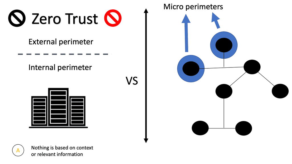
ZT and Microsegmentation
By implementing Zero Trust microsegmentation, all ingress/egress traffic hitting your virtual NIC cards will be compared against the firewall policies you configure. The packet will be dropped without a rule matching the specific traffic flow. All unrecognized traffic will be denied by default at the vNIC itself by a default deny rule. A positive security model uses whitelisting, where only things that are specifically allowed are accepted, and everything else is rejected.
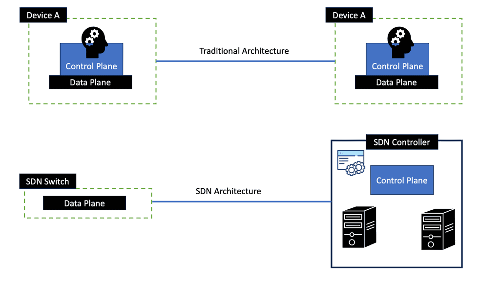
The Role of SDN
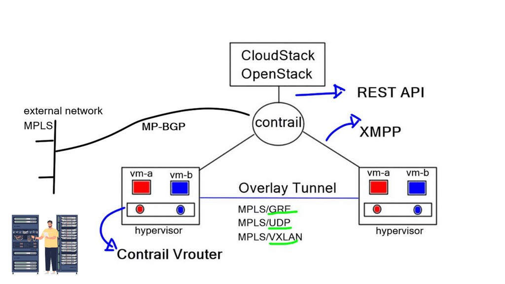
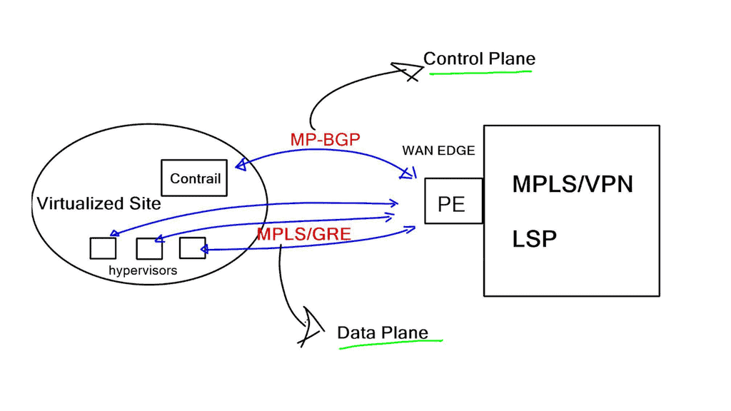
Recently, the ratio has changed, and the concepts of SDN apply to different types of network security components meeting various requirements. SDN enables network virtualization with many companies, such as VMware NSX, Midokura, Juniper Contrail, and Nuage, offering network virtualization solutions. The following post generally discusses network virtualization but focuses more on the NSX functionality.
For additional pre-information, you may find the following helpful:
Network Security Virtualization |
|
Back to basics with the Virtualization
Resource virtualization is crucial in fulfilling the required degree of adaptability. Therefore, we can perform Virtualization in many areas, including the Virtualization of servers, applications, storage devices, security appliances, and, not surprisingly, the network infrastructure. Server virtualization was the starting point for most of them.
Remember that security is a key driver and a building block behind the virtualized network. An essential component of a security policy is the definition of a network perimeter. Communications between the inside and the outside of the perimeter must occur through a checkpoint. With virtualization, this checkpoint can now be located in multiple network parts. Not just the traditional edge.
Key VMware NSX Points
1. Network Segmentation:
One of the fundamental aspects of VMware NSX Security is its ability to provide network segmentation. Organizations can create isolated environments for different applications and workloads by dividing the network into multiple virtual segments. This isolation helps prevent lateral movement of threats and limits the impact of a potential security breach.
2. Micro-segmentation:
With VMware NSX Security, organizations can implement micro-segmentation, which allows them to apply granular security policies to individual workloads within a virtualized environment. This level of control enables organizations to establish a zero-trust security model, where each workload is protected independently, reducing the attack surface and minimizing the risk of unauthorized access.
3. Distributed Firewall:
VMware NSX Security incorporates a distributed firewall that operates at the hypervisor level. Unlike traditional perimeter firewalls, which are typically centralized, the distributed firewall provides virtual machine-level security. This approach ensures that security policies are enforced regardless of the virtual machine’s location, providing consistent protection across the entire virtualized infrastructure.
4. Advanced Threat Prevention:
VMware NSX Security leverages advanced threat prevention techniques to detect and mitigate potential security threats. It incorporates intrusion detection and prevention systems (IDPS), malware detection, and network traffic analysis. These capabilities enable organizations to proactively identify and respond to potential security incidents, reducing the risk of data breaches and system compromises.
5. Automation and Orchestration:
Automation and orchestration are integral components of VMware NSX Security. With automation, organizations can streamline security operations, reducing the probability of human errors and speeding up the response to security incidents. Orchestration allows for integrating security policies with other IT processes, enabling consistent and efficient security management.
6. Integration with Existing Security Solutions:
VMware NSX Security can seamlessly integrate with existing security solutions, such as threat intelligence platforms, security information and event management (SIEM) systems, and endpoint protection tools. This integration enhances an organization’s overall security posture by aggregating security data from various sources and providing a holistic view of the network’s security landscape.
Network Security Virtualization
The Role of Network Virtualization
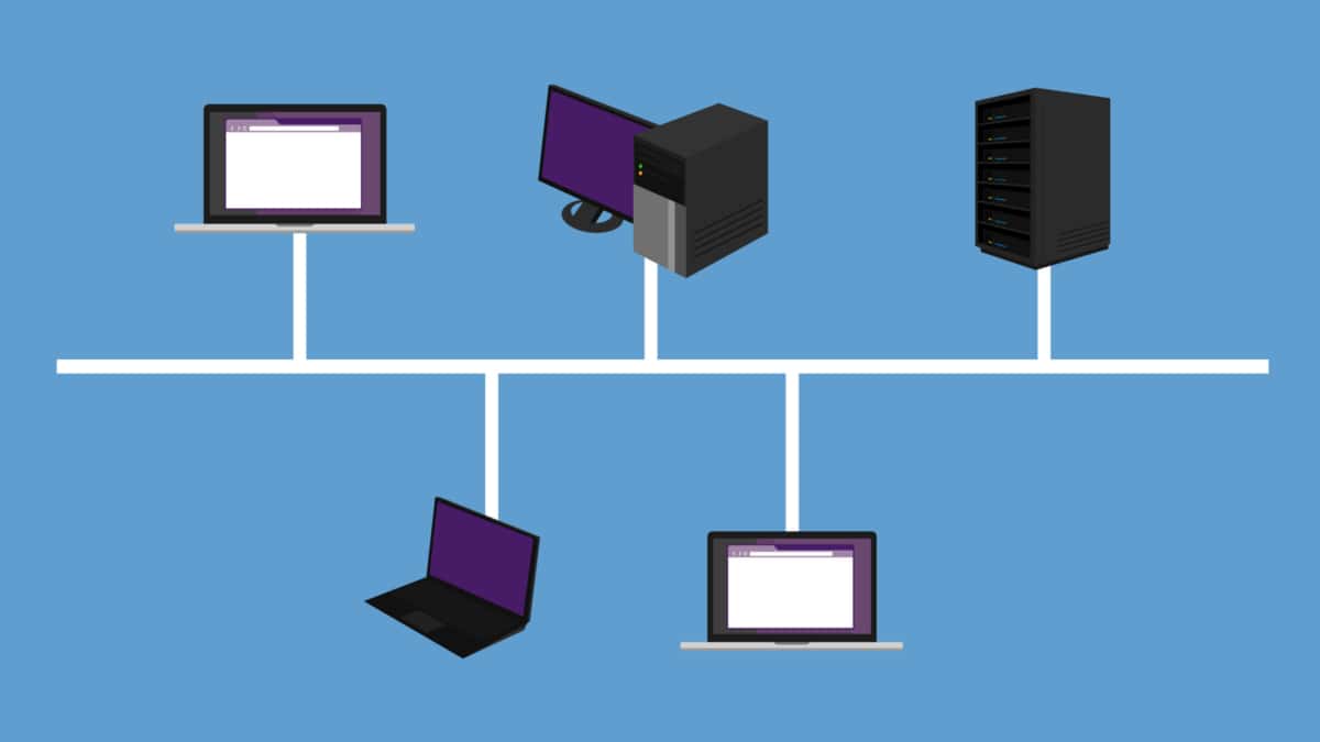
Virtualization provides network services independent of the physical infrastructure in its simplest form. Traditional network services were tied to physical boxes, lacking elasticity and flexibility. This results in many technical challenges, including central chokepoints, hair pinning, traffic trombones, and the underutilization of network devices.
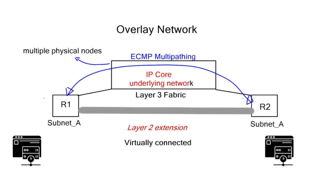
Network virtualization combats this and abstracts network services ( different firewalling such as context firewall, routing, etc.) into software, making it easier to treat the data center fabric as a pool of network services. When a service is put into the software, it gains elasticity and fluidity qualities that are not present with physical nodes. The physical underlay provides a connectivity model only concerned with endpoint connectivity.
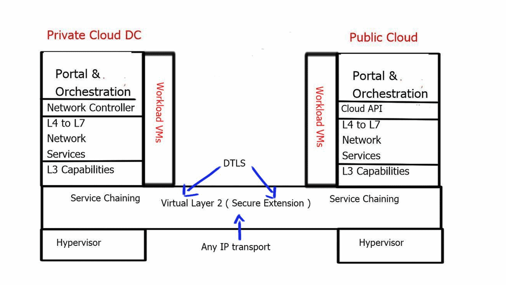
The software layer on top of the physical world provides the abstraction for the workloads, offering excellent application continuity. Now, we can take two data centers and make them feel like one. You can help facilitate this connection by incorporating kubernetes software to help delegate when a service needs to be done correctly, keeping on top of workload traffic.
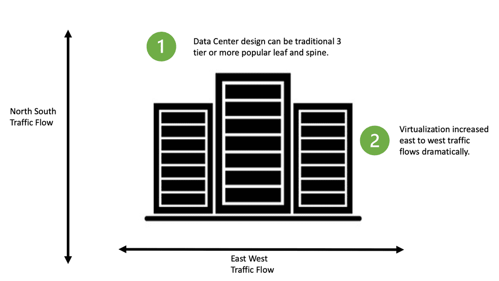
The Different Traffic Flows
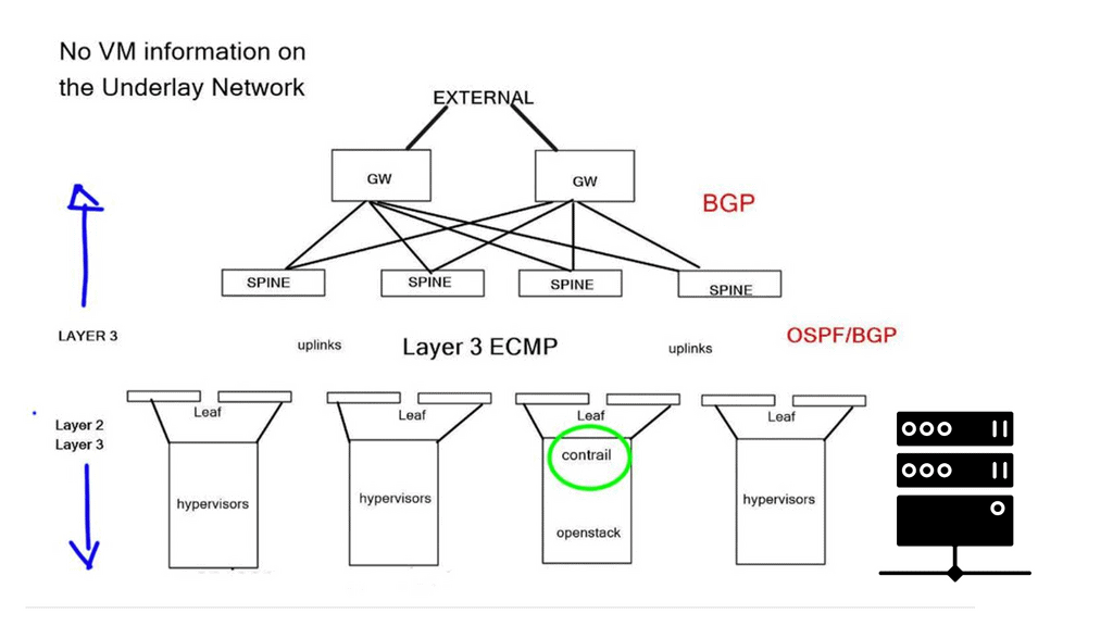
All east and west traffic flows via the tunnels. VMware’s NSX optimizes local egress traffic so that traffic exits the right data center and does not need to flow via the data center interconnect to egress. We used hacks with HSRP localization or complicated protocols such as LISP to overcome outbound TE with traditional designs.
The application has changed from the traditional client-server model, where you know how many hosts you run on top of. To an application that moves and scales on numerous physical nodes that may change. With network virtualization, we don’t need to know what physical Host the application is on, as all the computing, storage, and networking move with the application.
If application X moves to location X, all its related services move to location X, too. The network becomes a software abstract. Apps can have multiple tiers – front end, database, and storage with scale capabilities, automatically reacting to traffic volumes. It’s far more efficient to scale up docker containers with container schedules to meet traffic volumes than to deploy 100 physical servers, leaving them idle for half the year. If performance is not a vital issue, it makes sense to move everything to software.
VMware NSX Security: Changing Endpoints
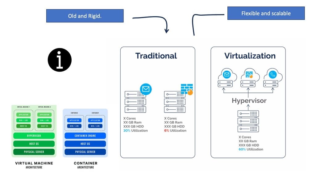
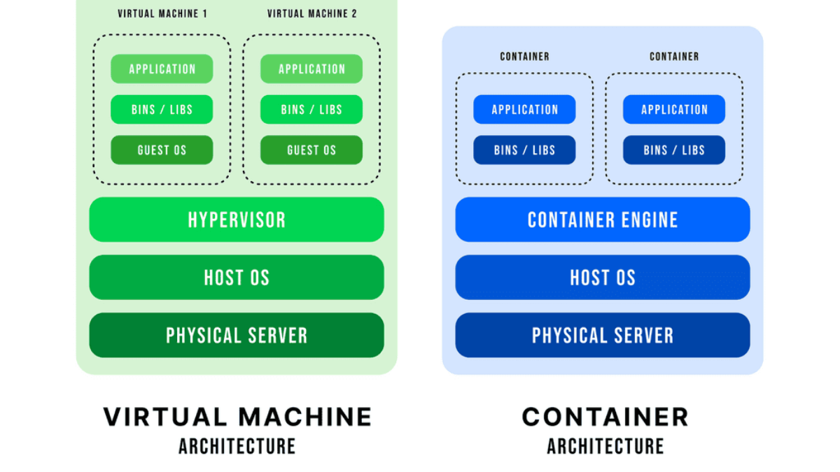
The endpoints the network must support have changed. We now have container based virtualization, VMs, and mobile and physical devices. Networking is evolving, and it’s all about connecting all these heterogeneous endpoints that are becoming very disconnected from the physical infrastructure. Traditionally, a server is connected to the network with an Ethernet port.
Then, virtualization came along, offering the ability to architect new applications. Instead of single servers hosting single applications, multiple VMs host different applications on a single physical server. More recently, we saw the introduction of docker containers, spawning in as little as 350ms.
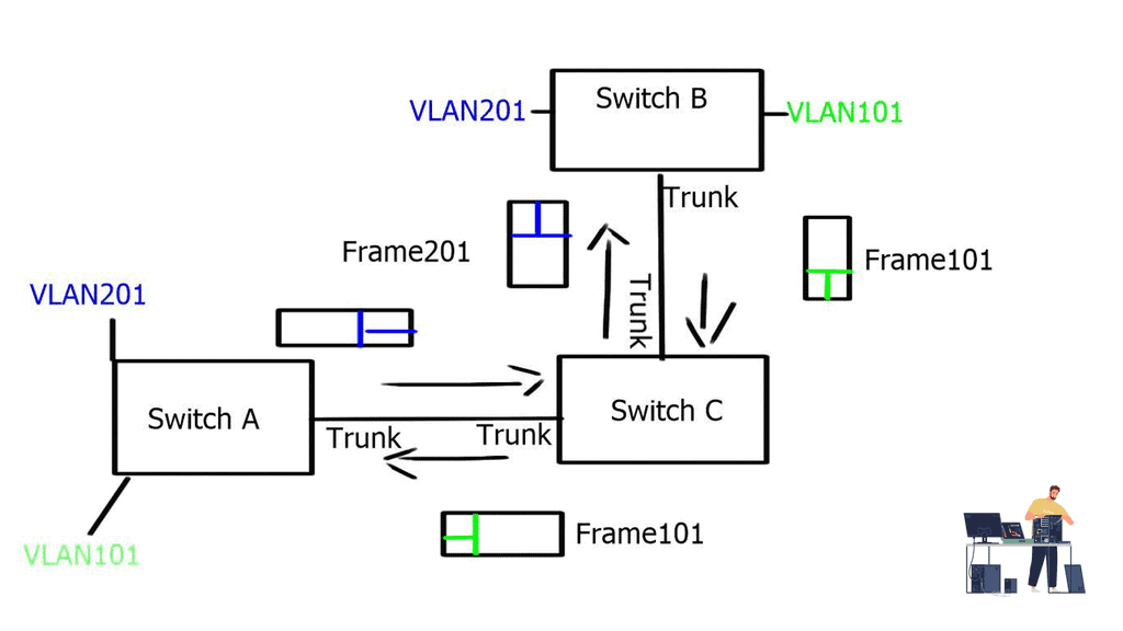
The Challenge with Traditional VM
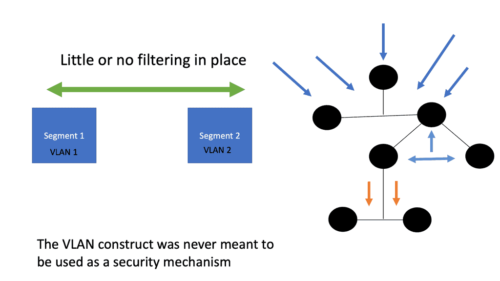
Traditional VLANs cannot meet this type of fluidity as each endpoint type has different network requirements. The network must now support conventional physical servers, VMs, and Docker containers. All these stacks must cross each other and, more importantly, be properly secured in a multitenant environment.
Can traditional networking meet this? VMware NSX is a reasonably mature product offering virtualized network and security services that can secure various endpoints.
Network endpoints have different trust levels. Administrators trust hypervisors more now, with only two VMware hypervisor attacks in the last few years. Unfortunately, the Linux kernel has numerous ways to attack it. Security depends on the attack surface, and an element with a large surface has more potential for exploitation. The Linux kernel has a large attack surface, while hypervisors have a small one.
The more options an attacker can exploit, the larger the attack surface. Containers run many workloads, so the attack surface is more extensive and varied. The virtual switch inside the container has a different trust level than a vswitch inside a hypervisor. Therefore, you must operate different security paradigms relating to containers than hypervisors.
A key point: VMware NSX Security and Network Security Virtualization.
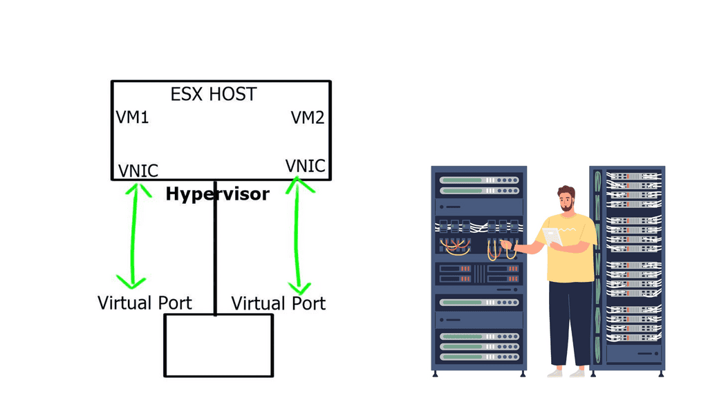
NSX provides isolation to all these endpoint types with microsegmentation. Microsegmentation allows you to apply security policy at a VM-NIC level. This offers the ability to protect east-west traffic and move policies with the workload.
This doesn’t mean that each VM NIC requires an individual configuration. NSX uses a distributed firewalls kernel module, and the hosts obtain the policy without individual config. Everything is controlled centrally but installed locally on each vSphere host. It scales horizontally, so you get more firewalls if you add more computing capacity.
All the policies are implemented in a distributed fashion, and the firewall is situated right in front of the VM in the hypervisor. So you can apply policy at a VM NIC level without hairpinning or trombone the traffic. Traffic doesn’t need to go across the data center to a central policy engine: offering optimum any to any traffic.
Even though the distributed firewall is a Kernel loadable module (KLM) of the ESXi Host, policy enforcement is at the VM’s vNIC.
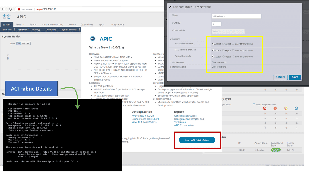
Network Security Virtualization: Policy Classification
A central selling point with NSX is that you get an NSX-distributed firewall. VMware operates with three styles of security:
- We have traditional network-focused 5-tuple matching.
- We then move up a layer with infrastructure-focused rules such as port groups, vCenter objects, etc.
- We have application-focused rule sets at a very high level, from the Web tier to the App tier permit TCP port 80.
Traditionally, we have used network-based rules, so the shift to application-based, while more efficient, will present the most barriers. People’s mindset needs to change. However, the real benefit of NSX comes from this type of endpoint labeling and security. Sometimes, more than a /8 is required!
What happens when you run out of /8? We start implementing kludges with NAT, etc. Security labeling has been based on IP addresses in the past, and we should start moving with tagging or other types of labeling.
IP addresses are just a way to get something from point A to point B, but if we can focus on different ways to class traffic, the IP address should be irrelevant to security classification. The less tied we are to IP addresses as a security mechanism, the better we will be.
With NSX, endpoints are managed based on high-level policy language that adequately describes the security function. IP is a terrible way to do this as it imposes hard limits on mobile VMs and reduces flexibility. The policy should be independent of IP address assignment.
Organizations must adopt robust and versatile security solutions in an era of constant cybersecurity threats. VMware NSX Security offers comprehensive features and capabilities that can significantly enhance network security. Organizations can build a robust security infrastructure that protects their data and infrastructure from evolving cyber threats by implementing network segmentation, micro-segmentation, a distributed firewall, advanced threat prevention, automation, and integration with existing security solutions. VMware NSX Security empowers organizations to take control of their network security and ensure the confidentiality, integrity, and availability of their critical assets.