Data Center Security Techniques
Data center network security encompasses a set of protocols, technologies, and practices to safeguard the infrastructure and data within data centers. It involves multiple layers of protection, including physical security, network segmentation, access controls, and threat detection mechanisms. By deploying comprehensive security measures, organizations can fortify their digital fortresses against potential breaches and unauthorized access.
Key Data Center Security Notes:
A. Physical Security Measures: Physical security forms the first line of defense for data centers. This includes biometric access controls, surveillance cameras, and restricted entry points. By implementing these measures, organizations can limit physical access to critical infrastructure and prevent unauthorized tampering or theft.
B. Network Segmentation: Segmenting a data center network into isolated zones helps contain potential breaches and limit the lateral movement of threats. By dividing the network into distinct segments based on user roles, applications, or sensitivity levels, organizations can minimize the impact of an attack, ensuring that compromised areas can be contained without affecting the entire network.
C. Access Controls: Strong access controls are crucial for data center network security. These controls involve robust authentication mechanisms, such as multi-factor authentication and role-based access control (RBAC), to ensure that only authorized personnel can access critical resources. Regularly reviewing and updating access privileges further strengthens the security posture.
D. Threat Detection and Prevention: Data center networks should employ advanced threat detection and prevention mechanisms. This includes intrusion detection systems (IDS) and intrusion prevention systems (IPS) that monitor network traffic for suspicious activities and proactively mitigate potential threats. Additionally, deploying firewalls, antivirus software, and regular security patches helps protect against known vulnerabilities.
E: Data Encryption and Protection: Data encryption is a critical measure in safeguarding data both at rest and in transit. By encoding data, encryption ensures that even if it is intercepted, it remains unreadable without the proper decryption keys. Cisco’s encryption solutions offer comprehensive protection for data exchange within and outside the data center. Additionally, implementing data loss prevention (DLP) strategies helps in identifying, monitoring, and protecting sensitive data from unauthorized access or leakages.
Data Center Security – SCCs
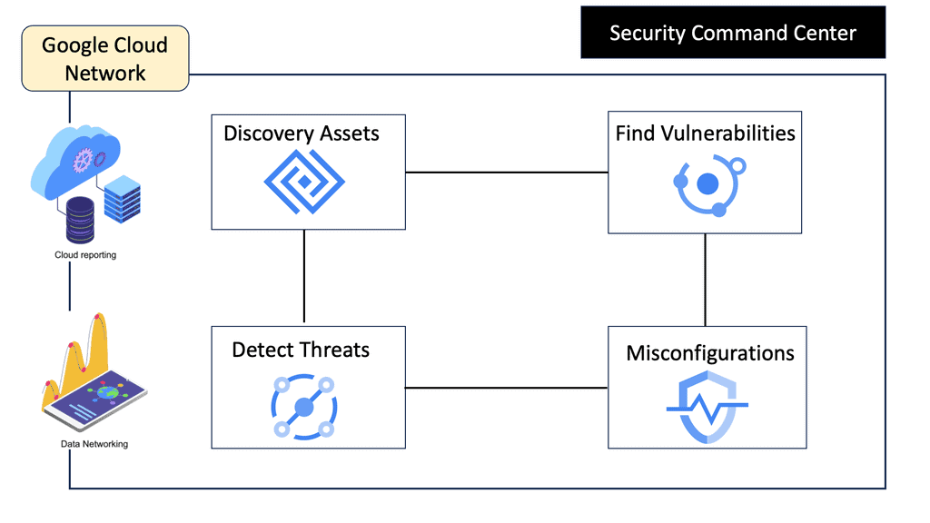
A: **Understanding Security Command Center**
Security Command Center (SCC) is a comprehensive security management tool that provides visibility into your Google Cloud assets and their security status. It acts as a centralized hub, enabling you to identify potential vulnerabilities and threats before they escalate into serious issues. By leveraging SCC, businesses can ensure their data centers remain secure, compliant, and efficient.
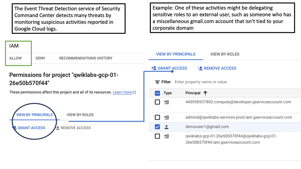
**Detecting Threats with Precision**
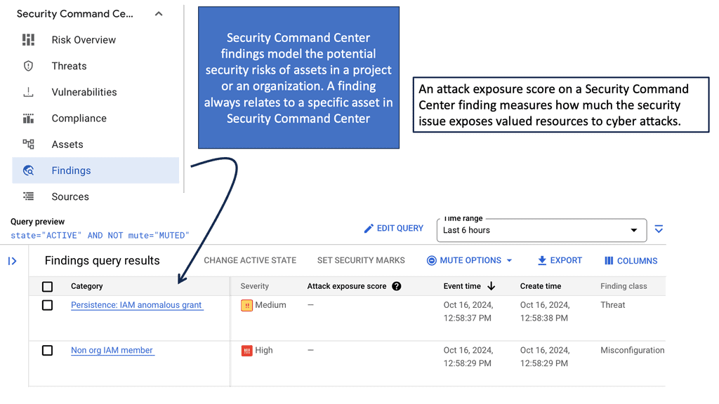
One of the standout features of Security Command Center is its ability to detect threats with precision. Utilizing advanced threat detection capabilities, SCC continuously monitors your cloud environment for signs of suspicious activity. It leverages machine learning algorithms and Google’s vast threat intelligence to identify anomalies, ensuring that potential threats are flagged before they can cause harm. This proactive approach to security allows organizations to respond swiftly, minimizing potential damage.
**Investigating Threats with Confidence**
Once a threat is detected, it’s crucial to have the tools necessary to investigate it thoroughly. Security Command Center provides detailed insights into security incidents, offering a clear view of what happened, when, and how. This level of transparency empowers security teams to conduct comprehensive investigations, trace the root cause of incidents, and implement effective remediation strategies. With SCC, businesses can maintain control over their security landscape, ensuring continuous protection against cyber threats.
**Enhancing Data Center Security on Google Cloud**
Integrating Security Command Center into your Google Cloud infrastructure significantly enhances your data center’s security framework. SCC provides a holistic view of your security posture, enabling you to assess risks, prioritize security initiatives, and ensure compliance with industry standards. By adopting SCC, organizations can bolster their defenses, safeguarding their critical data assets and maintaining customer trust.
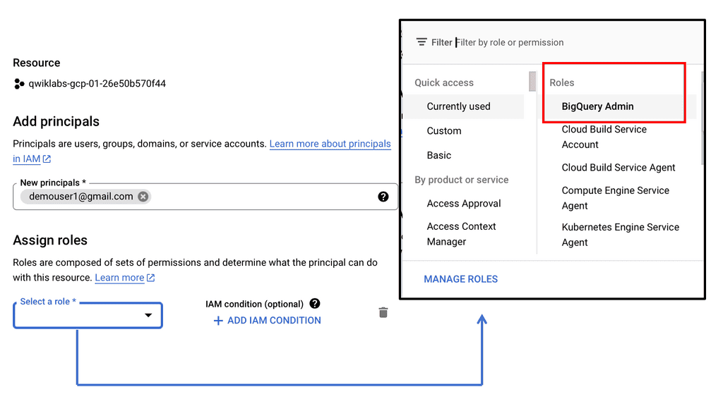
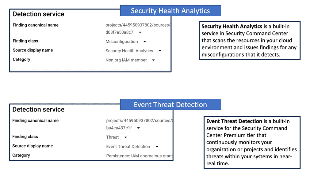
Example: Event Threat Protection & Security Health Analysis
Data Center Security – NEGs
B: **Understanding Network Endpoint Groups**
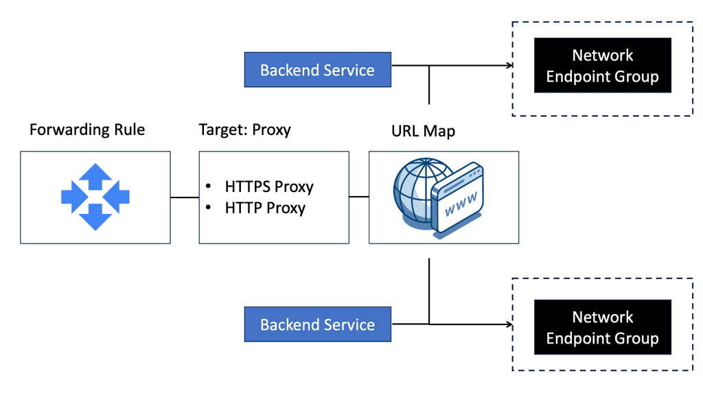
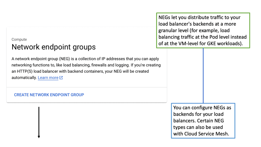
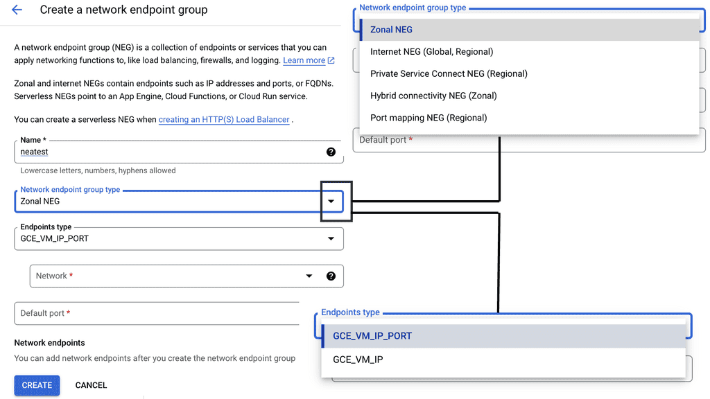
Network endpoint groups are collections of network endpoints, such as virtual machine instances or internet protocol addresses, that you can use to manage and direct traffic within Google Cloud. NEGs are particularly useful for deploying applications across multiple environments, providing the flexibility to choose between different types of endpoints. This feature is pivotal when dealing with a hybrid architecture, ensuring that traffic is efficiently directed to the most appropriate resource, whether it resides in your cloud infrastructure or on-premises.
**The Role of NEGs in Data Center Security**
One of the standout benefits of using network endpoint groups is their contribution to enhancing data center security. By enabling precise traffic management, NEGs allow for better segmentation and isolation of network traffic, reducing the risk of unauthorized access. With the ability to direct traffic to specific endpoints, NEGs provide an additional layer of security, ensuring that only authorized users can access sensitive data and applications. This capability is crucial in today’s cybersecurity landscape, where threats are becoming increasingly sophisticated.
**Integrating NEGs with Google Cloud Services**
Network endpoint groups seamlessly integrate with various Google Cloud services, making them a versatile tool for optimizing your cloud environment. For instance, NEGs can be used in conjunction with Google Cloud’s load balancing services to distribute traffic across multiple endpoints, enhancing the availability and reliability of your applications. Additionally, NEGs can work with Google Cloud’s Kubernetes Engine, allowing for more granular control over how traffic is routed to your containerized applications. This integration ensures that your applications can scale efficiently while maintaining high performance.
**Best Practices for Implementing NEGs**
When implementing network endpoint groups, it’s essential to follow best practices to maximize their effectiveness. Start by clearly defining your endpoint groups based on your application architecture and traffic patterns. Ensure that endpoints are regularly monitored and maintained to prevent potential bottlenecks. Additionally, leverage Google’s monitoring and logging tools to gain insights into traffic patterns and potential security threats. By adhering to these best practices, you can harness the full potential of NEGs and ensure a robust and secure cloud infrastructure.
Data Center Security – VPC Service Control
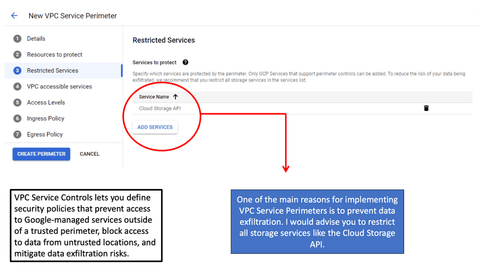
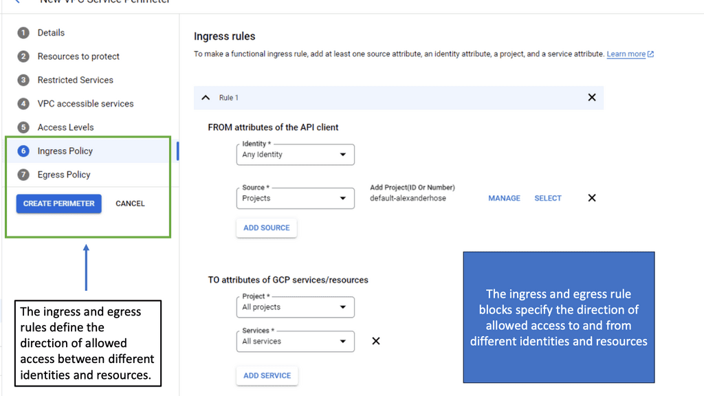
C: **How VPC Service Controls Work**
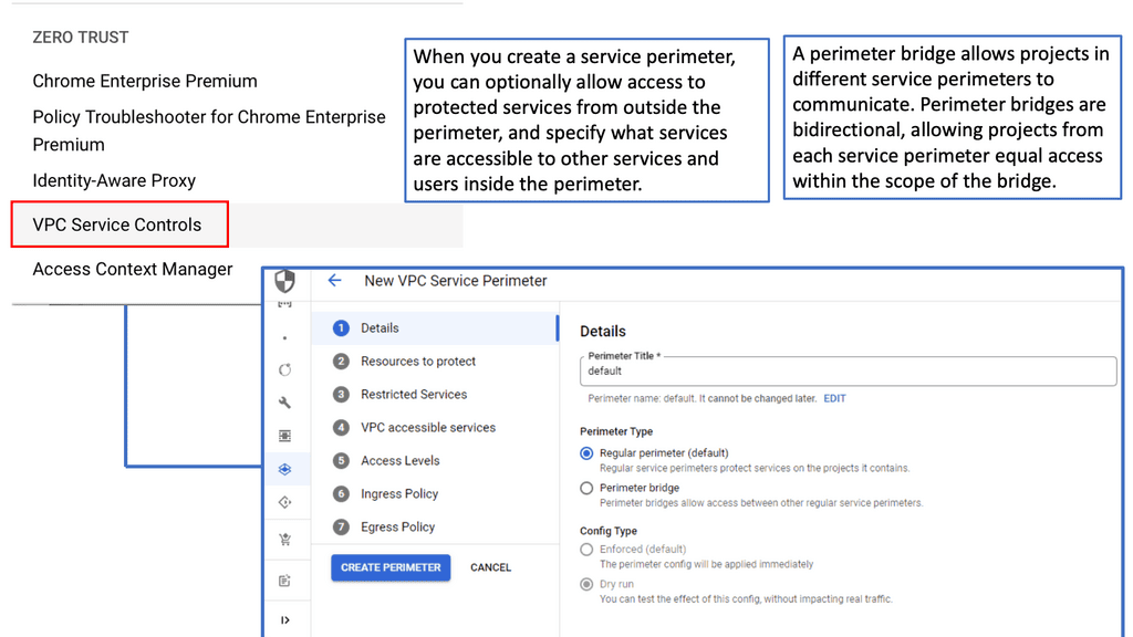
VPC Service Controls work by creating virtual perimeters around the Google Cloud resources you want to protect. These perimeters restrict unauthorized access and data transfer, both accidental and intentional. When a service perimeter is set up, it enforces policies that prevent data from leaving the defined boundary without proper authorization. This means that even if credentials are compromised, sensitive data cannot be moved outside the specified perimeter, thus providing an additional security layer over Google Cloud’s existing IAM roles and permissions.

**Integrating VPC Service Controls with Your Cloud Strategy**
Integrating VPC Service Controls into your cloud strategy can significantly bolster your security framework. Begin by identifying the critical services and data that require the most protection. Next, define the service perimeters to encompass these resources. It’s essential to regularly review and update these perimeters to adapt to changes in your cloud environment. Additionally, leverage Google Cloud’s monitoring tools to gain insights and alerts on any unauthorized access attempts. This proactive approach ensures that your cloud infrastructure remains resilient against evolving threats.
**Best Practices for Implementing VPC Service Controls**
To maximize the effectiveness of VPC Service Controls, organizations should follow best practices. First, ensure that your team is well-versed in both Google Cloud services and the specifics of VPC Service Controls. Regular training sessions can help keep everyone up to date with the latest features and security measures. Secondly, implement the principle of least privilege by granting the minimal level of access necessary for users and services. Lastly, continuously monitor and audit your cloud environment to detect and respond to any anomalies swiftly.
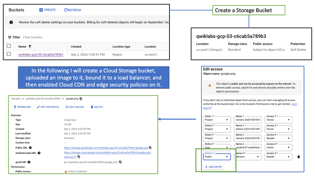
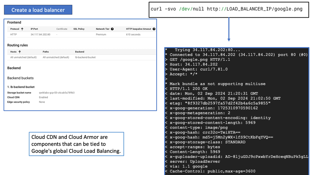
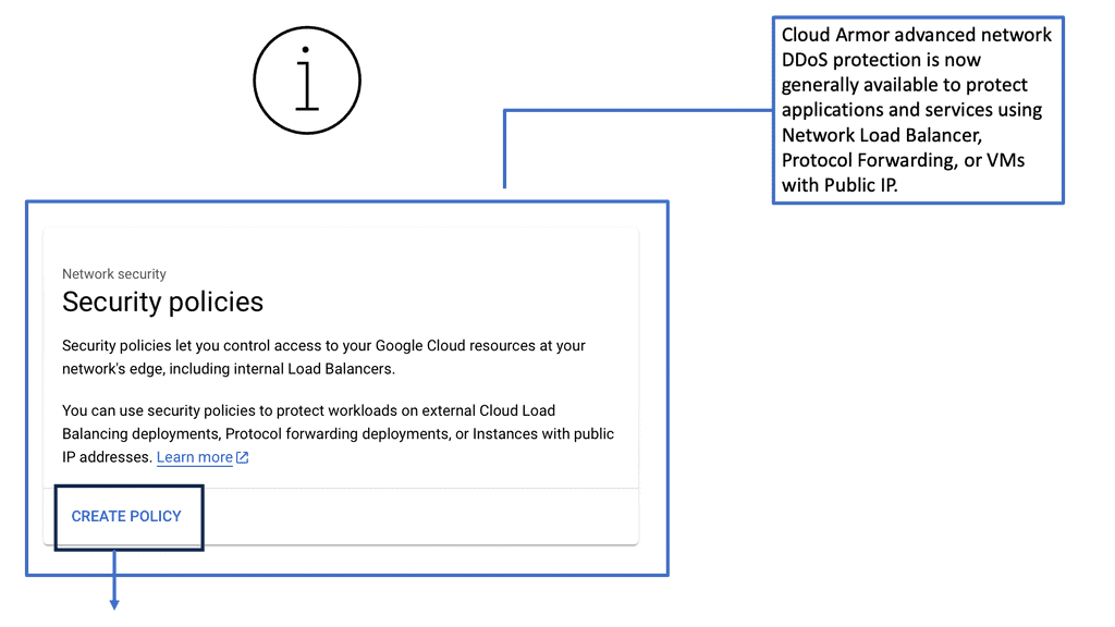
Data Center Security – Cloud Armor
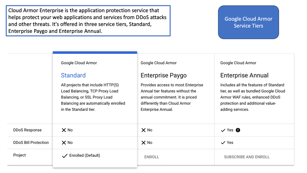
D: **Understanding Cloud Armor**
Cloud Armor is a cloud-based security service that leverages Google’s global infrastructure to provide advanced protection for your applications. It offers a range of security features, including DDoS protection, WAF (Web Application Firewall) capabilities, and threat intelligence. By utilizing Cloud Armor, businesses can defend against various cyber threats, such as SQL injection, cross-site scripting, and other web vulnerabilities.
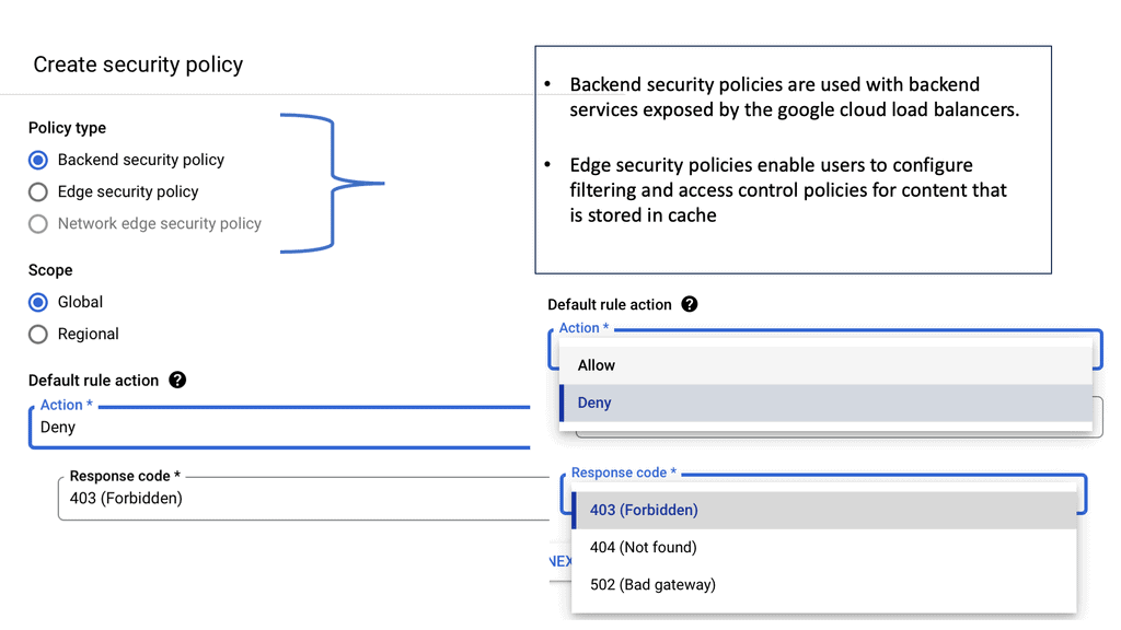
**The Power of Edge Security Policies**
One of the standout features of Cloud Armor is its edge security policies. These policies enable businesses to enforce security measures at the network edge, closer to the source of potential threats. By doing so, Cloud Armor can effectively mitigate attacks before they reach your applications, reducing the risk of downtime and data breaches. Edge security policies can be customized to suit your specific needs, allowing you to create tailored rules that address the unique security challenges faced by your organization.
**Implementing Cloud Armor in Your Security Strategy**
Integrating Cloud Armor into your existing security strategy is a straightforward process. Begin by assessing your current security posture and identifying any potential vulnerabilities. Next, configure Cloud Armor’s edge security policies to address these vulnerabilities and provide an additional layer of protection. Regularly monitor and update your policies to ensure they remain effective against emerging threats. By incorporating Cloud Armor into your security strategy, you can enhance your overall security posture and protect your digital assets more effectively.
**Benefits of Using Cloud Armor**
There are numerous benefits to using Cloud Armor for your security needs. Firstly, its global infrastructure ensures low latency and high availability, providing a seamless experience for your users. Secondly, the customizable edge security policies allow for granular control over your security measures, ensuring that you can address specific threats as they arise. Additionally, Cloud Armor’s integration with other Google Cloud services enables a unified security approach, streamlining your security management and monitoring efforts.
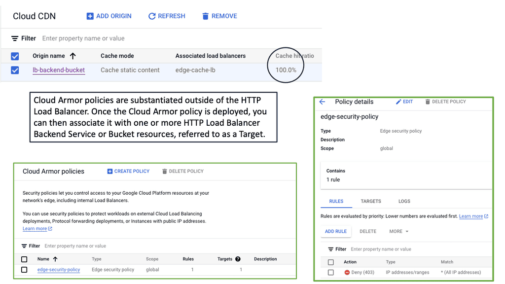
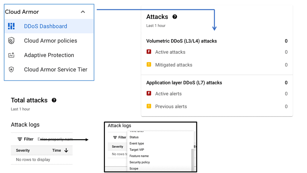
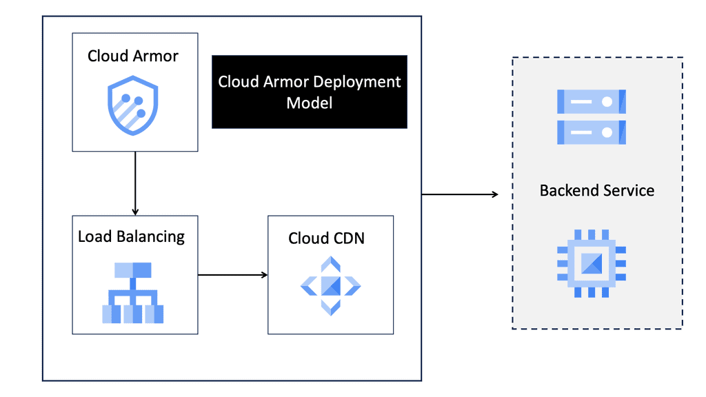
### The Role of Cloud Armor in Cyber Defense
Google Cloud Armor serves as a robust defense mechanism against DDoS attacks, providing enterprises with scalable and adaptive security solutions. Built on Google Cloud’s global network, Cloud Armor leverages the same infrastructure that protects Google’s services, offering unparalleled protection against high-volume attacks. By dynamically filtering malicious traffic, it ensures that legitimate requests reach their destination without disruption, maintaining the availability and performance of online services.
### Enhancing Data Center Security
Data centers, the backbone of modern business operations, face unique security challenges. Cloud Armor enhances data center security by providing a first line of defense against DDoS threats. Its customizable security policies allow organizations to tailor their defenses to specific needs, ensuring that only legitimate traffic flows into data centers. Coupled with advanced threat intelligence, Cloud Armor adapts to emerging threats, keeping data centers secure and operational even during sophisticated attack attempts.
### Key Features of Cloud Armor
Cloud Armor offers a range of features designed to shield enterprises from DDoS attacks, including:
– **Adaptive Protection**: Continuously analyzes traffic patterns to identify and block malicious activities in real-time.
– **Global Load Balancing**: Distributes traffic across multiple servers, preventing any single point from becoming overwhelmed.
– **Customizable Security Policies**: Allows businesses to define rules and policies that match their specific security requirements.
– **Threat Intelligence**: Utilizes Google’s vast threat database to stay ahead of emerging threats and enhance protection measures.
 Data Center Security – FortiGate
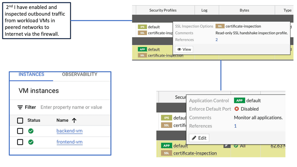
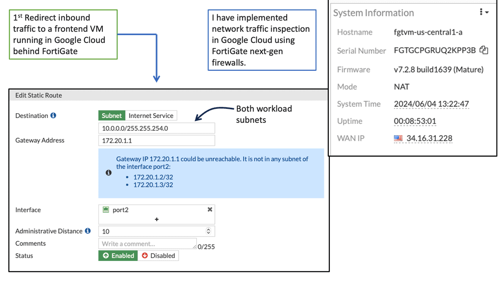
E: FortiGate and Google Cloud
Cloud security has become a top concern for organizations worldwide. The dynamic nature of cloud environments necessitates a proactive approach to protect sensitive data, prevent unauthorized access, and mitigate potential threats. Google Compute Engine offers a reliable and scalable infrastructure, but it is essential to implement additional security measures to fortify your cloud resources.
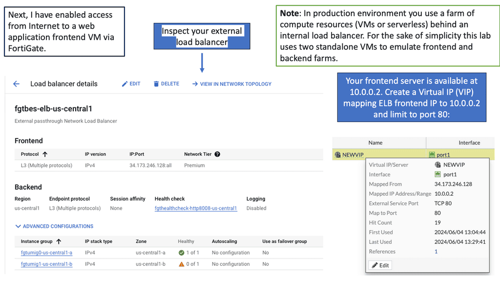
FortiGate, a leading network security solution, seamlessly integrates with Google Compute Engine to enhance the security posture of your cloud environment. With its advanced features, including firewall, VPN, intrusion prevention system (IPS), and more, FortiGate provides comprehensive protection for your compute resources.
Firewall Protection: FortiGate offers a robust firewall solution, allowing you to define and enforce granular access policies for inbound and outbound network traffic. This helps prevent unauthorized access attempts and safeguards your cloud infrastructure from external threats.
VPN Connectivity: With FortiGate, you can establish secure VPN connections between your on-premises network and Google Compute Engine instances. This ensures encrypted communication channels, protecting data in transit and enabling secure remote access.
Intrusion Prevention System (IPS): FortiGate’s IPS capabilities enable real-time detection and prevention of potential security breaches. It actively monitors network traffic, identifies malicious activities, and takes immediate action to block threats, ensuring the integrity of your compute resources.
Data Center Security – PCS
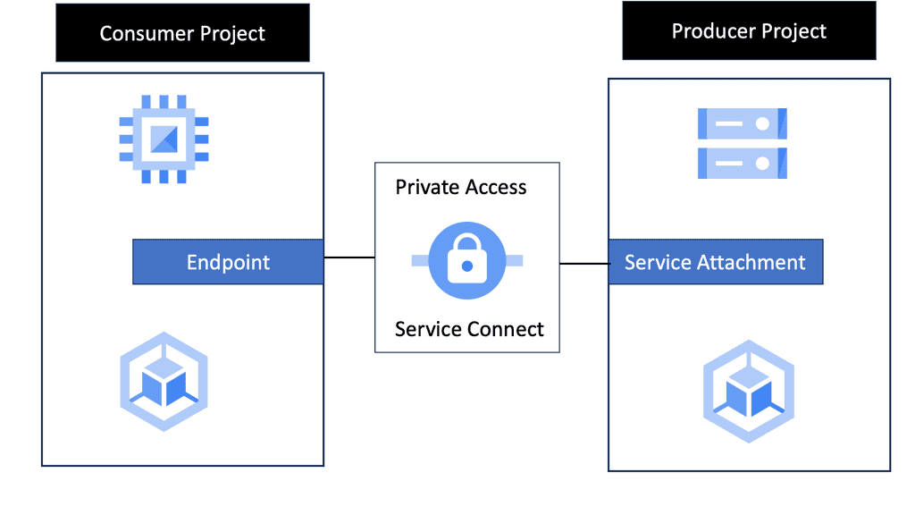
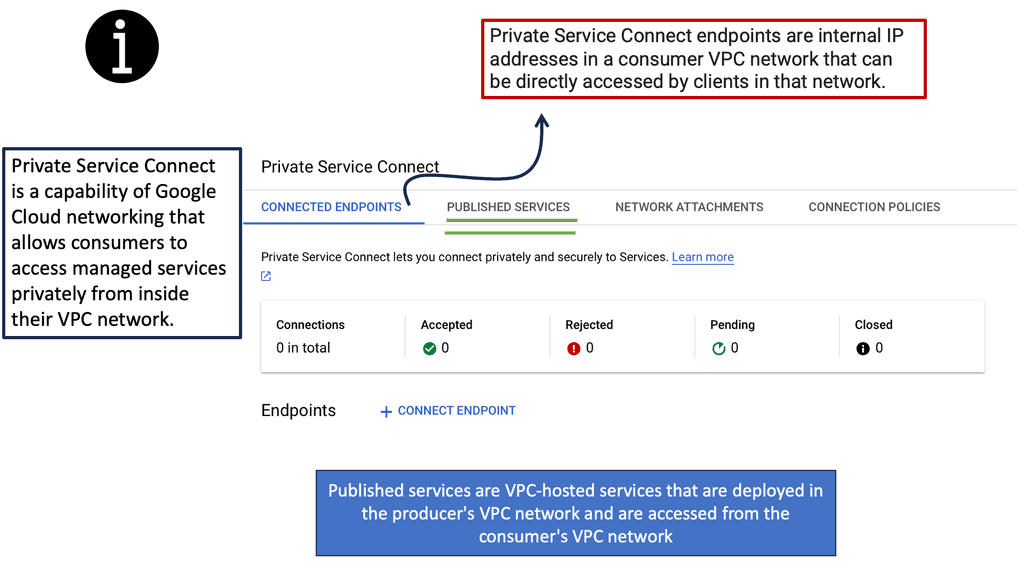
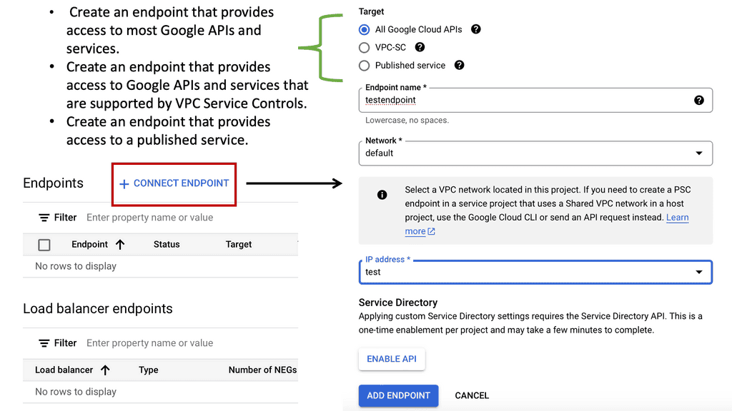
What is Private Service Connect?
Private Service Connect is a Google Cloud feature that allows you to securely connect services from different Virtual Private Clouds (VPCs) without exposing them to the public internet. By using internal IP addresses, Private Service Connect ensures that your data remains within the confines of Google’s secure network, protecting it from external threats and unauthorized access.
—
### Enhancing Security with Google Cloud
Google Cloud’s infrastructure is built with security at its core, and Private Service Connect is no exception. By routing traffic through Google’s private network, this feature reduces the attack surface, making it significantly harder for malicious entities to intercept or breach sensitive data. Furthermore, it supports encryption, ensuring that data in transit is protected against eavesdropping and tampering.
### Seamless Integration and Flexibility
One of the standout benefits of Private Service Connect is its seamless integration with existing Google Cloud services. Whether you’re running applications on Compute Engine, using Cloud Storage, or leveraging BigQuery, Private Service Connect allows you to connect these services effortlessly, without the need for complex configurations. This flexibility ensures that businesses can tailor their cloud infrastructure to meet their specific security and connectivity needs.
**Cisco ACI and Segmentation**
Network segmentation involves dividing a network into multiple smaller segments or subnetworks, isolating different types of traffic, and enhancing security. Cisco ACI offers an advanced network segmentation framework beyond traditional VLAN-based segmentation. It enables the creation of logical network segments based on business policies, applications, and user requirements.
Cisco ACI is one of many data center topologies that must be secured. It lacks a data center firewall and has a zero-trust model. However, more is required; the policy must say what can happen. Firstly, we must create a policy. You have Endpoint groups (EPG) and a contract. These would be the initial security measures. Think of a contract as the policy statement and an Endpoint group as a container or holder for applications of the same security level.
**Cisco ACI & Micro-segmentation**
Micro-segmentation has become a buzzword in the networking industry. Leaving the term and marketing aside, it is easy to understand why customers want its benefits. Micro-segmentation’s primary advantage is reducing the attack surface by minimizing lateral movement in the event of a security breach. With traditional networking technologies, this isn’t easy to accomplish. However, SDN technologies enable an innovative approach by allowing degrees of flexibility and automation that are impossible with traditional network management and operations. This makes micro-segmentation possible.
For those who haven’t explored this topic yet, Cisco ACI has ESG. ESGs are an alternative approach to segmentation that decouples it from the early concepts of forwarding and security associated with Endpoint Groups. Thus, segmentation and forwarding are handled separately by ESGs, allowing for greater flexibility and possibilities.
**Cisco ACI ESGs**
Cisco ACI ESGs are virtual appliances that provide advanced network services within the Cisco ACI fabric. They offer various functionalities, including firewalling, load balancing, and network address translation, all seamlessly integrated into the ACI architecture. By utilizing ESGs, organizations can achieve centralized network management while maintaining granular control over their network policies.
One key advantage of Cisco ACI ESGs is their ability to streamline network management. With ESGs, administrators can easily define and enforce network policies across the entire ACI fabric, eliminating the need for complex and time-consuming manual configurations. The centralized management provided by ESGs enhances operational efficiency and reduces the risk of human errors.
Security is a top priority for any organization, and Cisco ACI ESGs deliver robust security features. With built-in firewall capabilities and advanced threat detection mechanisms, ESGs ensure only authorized traffic flows through the network. Furthermore, ESGs support micro-segmentation, allowing organizations to create isolated security zones within their network, preventing any lateral movement of threats.
**Cisco ACI and ACI Service Graph**
The ACI service graph is how Layer 4 to Layer 7 functions or devices can be integrated into ACI. This helps ACI redirect traffic between different security zones of FW or load balancer. The ACI L4-L7 services can be anything from load balancing and firewalling to advanced security services. Then, we have ACI segments that reduce the attack surface to an absolute minimum.
Then, you can add an ACI service graph to insert your security function that consists of ACI L4-L7 services. Now, we are heading into the second stage of security. What we like about this is the ease of use. If your application is removed, all the dots, such as the contract, EPG, ACI service graph, and firewall rules, get released. Cisco calls this security embedded in the application and allows automatic remediation, a tremendous advantage for security functionality insertion.
Cisco Data Center Security Technologies
Example Technology: NEXUS MAC ACLs
MAC ACLs, or Media Access Control Access Control Lists, are essential for controlling network traffic based on MAC addresses. Unlike traditional IP-based ACLs, MAC ACLs operate at Layer 2 of the OSI model, granting granular control over individual devices within a network. Network administrators can enforce security policies and mitigate unauthorized access by filtering traffic at the MAC address level.
MAC ACL Key Advantages
The utilization of MAC ACLs brings forth several noteworthy advantages. Firstly, they provide an additional layer of security by complementing IP-based ACLs. This dual-layered approach ensures comprehensive protection against potential threats. Moreover, MAC ACLs enable the isolation of specific devices or groups, allowing for enhanced segmentation and network organization. Additionally, their ability to filter traffic at Layer 2 minimizes the strain on network resources, resulting in optimized performance.

Understanding VLAN ACLs
Before diving into the configuration details, let’s understand VLAN ACLs clearly. VLAN ACLs are rules that control traffic flow between VLANs in a network. They act as filters, allowing or denying specific types of traffic based on defined criteria such as source/destination IP addresses, protocol types, or port numbers. By effectively implementing VLAN ACLs, network administrators can control and restrict resource access, mitigate security threats, and optimize network performance.
ACLs – Virtual Security Fence
ACLs (Access Control Lists) are rules that determine whether to permit or deny network traffic. They act as a virtual security fence, controlling data flow between network segments. ACLs can be applied at various points in the network, including routers, switches, and firewalls. Traditionally, ACLs were used to control traffic between different subnets. Still, with the advent of VLANs, ACLs can now be applied at the VLAN level, offering granular control over network traffic.
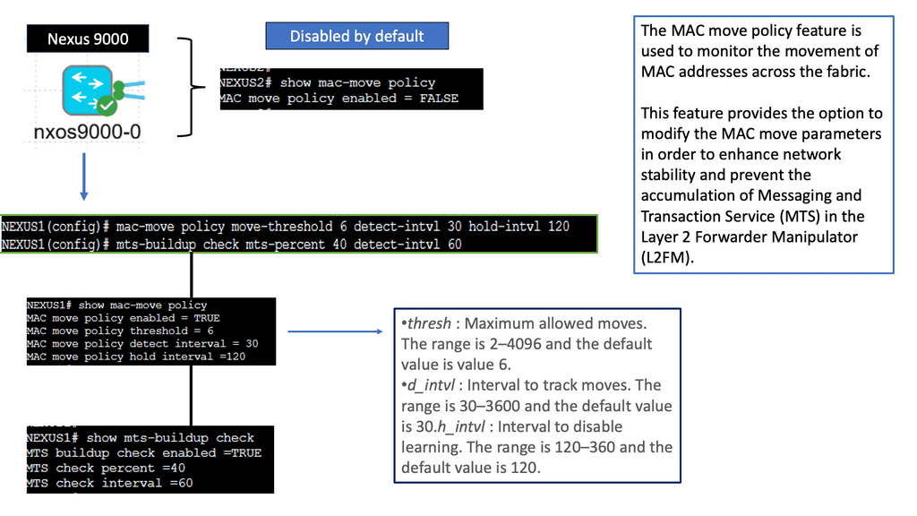
 What is a MAC Move Policy?
In the context of Cisco NX-OS devices, a MAC move policy dictates how MAC addresses are handled when they move from one port to another within the network. It defines the device’s actions, such as flooding, forwarding, or blocking the MAC address. This policy ensures efficient delivery of data packets and prevents unnecessary flooding, reducing network congestion.
Types of MAC Move Policies
Cisco NX-OS devices offer different MAC move policies to cater to diverse network requirements. The most commonly used policies include:
1. Forward: In this policy, the device updates its MAC address table and forwards data packets to the new destination port.
2. Flood: When a MAC address moves, the device floods the data packets to all ports within the VLAN, allowing the destination device to learn the new location of the MAC address.
3. Drop: This policy drops data packets destined for the moved MAC address, effectively isolating it from the network.
Data Center Visibility Technologies
**Understanding sFlow**
sFlow is a sampling-based network monitoring technology that allows network administrators to gain real-time visibility into their network traffic. By continuously sampling packets at wire speed, sFlow provides a comprehensive view of network behavior without imposing significant overhead on the network devices.
sFlow Key Advantages
On Cisco NX-OS, sFlow brings a host of benefits for network administrators. Firstly, it enables proactive network monitoring by providing real-time visibility into network traffic patterns, allowing administrators to identify and address potential issues quickly. Secondly, sFlow on Cisco NX-OS facilitates capacity planning by providing detailed insights into traffic utilization, enabling administrators to optimize network resources effectively.

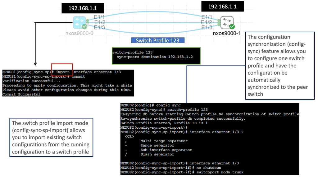
Understanding Nexus Switch Profiles
To begin our exploration, we must grasp the fundamentals of Nexus Switch Profiles. These profiles are essentially templates that define the configuration settings for Nexus switches. Network administrators can easily apply consistent configurations across multiple switches by creating profiles, reducing manual effort and potential errors. These profiles include VLAN configurations, interface settings, access control lists, and more.
Nexus Switch Profiles Key Advantages
Nexus Switch Profiles offer numerous benefits for network administrators and organizations. First, they streamline the configuration process by providing a centralized and standardized approach. This not only saves time but also ensures consistency across the network infrastructure. Additionally, profiles allow for easy scalability, enabling the swift deployment of new switches with pre-defined configurations. Moreover, these profiles enhance security by enforcing consistent access control policies and reducing the risk of misconfigurations.
 Related: For pre-information, you may find the following posts helpful:
Data Center Security with Cisco ACI
Cisco ACI includes many tools to implement and enhance security and segmentation from day 0. We already mentioned tenant objects like EPGs, and then for policy, we have contracts permitting traffic between them. We also have micro-segmentation with Cisco ACI. Even though the ACI fabric can deploy zoning rules with filters and act as a distributed data center firewall, the result is comparable to a stateless set of access lists ACLs.
As a result, they can provide coarse security for traffic flowing through the fabric. However, for better security, we can introduce deep traffic inspection capabilities like application firewalls, intrusion detection (prevention) systems (IDS/IPS), or load balancers, which often secure application workloads.
Cisco ACI – Application-centric security
ACI security addresses security concerns with several application-centric infrastructure security options. You may have heard of the allowlist policy model. This is the ACI security starting point, meaning only something can be communicated if policy allows it. This might prompt you to think that a data center firewall is involved. Still, although the ACI allowlist model does change the paradigm and improves how you apply security, it is only analogous to access control lists within a switch or router.
Cisco Secure Firewall Integration
We need additional protection. So, further protocol inspection and monitoring are still required, which data center firewalls and intrusion prevention systems (IPSs) do very well and can be easily integrated into your ACI network. Here, we can introduce Cisco Firepower Threat Defence (FTD) to improve security with Cisco ACI.
**Starting ACI Security**
**ACI Contracts**
In network terminology, contracts are a mechanism for creating access lists between two groups of devices. This function was initially developed in the network via network devices using access lists and then eventually managed by firewalls of various types, depending on the need for deeper packet inspection. As the data center evolved, access-list complexity increased.
Adding devices to the network that require new access-list modifications could become increasingly complex. While contracts satisfy the security requirements handled by access control lists (ACLs) in conventional network settings, they are a more flexible, manageable, and comprehensive ACI security solution.
Contracts control traffic flow within the ACI fabric between EPGs and are configured between EPGs or between EPGs and L3out. Contracts are assigned a scope of Global, Tenant, VRF, or Application Profile, which limits their accessibility.
**Challenge: Static ACLs**
With traditional data center security design, we have standard access control lists (ACLs) with several limitations the ACI fabric security model addresses and overcomes. First, the conventional ACL is very tightly coupled with the network topology. They are typically configured per router or switch ingress and egress interface and are customized to that interface and the expected traffic flow through those interfaces.
**Management Complexity**
Due to this customization, they often cannot be reused across interfaces, much less across routers or switches. In addition, traditional ACLs can be very complicated because they contain lists of specific IP addresses, subnets, and protocols that are allowed and many that are not authorized. This complexity means they are challenging to maintain and often grow as administrators are reluctant to remove any ACL rules for fear of creating a problem.
**ACI Fabric Security – Contracts, Filters & Labels**
The ACI fabric security model addresses these ACL issues. Cisco ACI administrators use contract, filter, and label managed objects to specify how groups of endpoints are allowed to communicate.
The critical point is that these managed objects are not tied to the network’s topology because they are not applied to a specific interface. Instead, they are rules that the network must enforce irrespective of where these endpoints are connected. So, security follows the workloads, allowing topology independence.
Furthermore, this topology independence means these managed objects can easily be deployed and reused throughout the data center, not just as specific demarcation points. The ACI fabric security model uses the endpoint grouping construct directly, so allowing groups of servers to communicate with one another is simple. With a single rule in a contract, we can allow an arbitrary number of sources to speak with an equally random number of destinations.
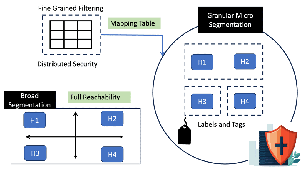
Micro-segmentation in ACI
We know that perimeter security is insufficient these days. Once breached, lateral movement can allow bad actors to move within large segments to compromise more assets. Traditional segmentation based on large zones gives bad actors a large surface to play with. Keep in mind that identity attacks are hard to detect.
How can you tell if a bad actor moves laterally through the network with compromised credentials or if an IT administrator is carrying out day-to-day activities? Micro-segmentation can improve the security posture inside the data center. Now, we can perform segmentation to minimize segment size and provide lesser exposure for lateral movement due to a reduction in the attack surface.
**ACI Segments**
ACI microsegmentation refers to segmenting an application-centric infrastructure into smaller, more granular units. This segmentation allows for better control and management of network traffic, improved security measures, and better performance. Organizations implementing an ACI microsegmentation solution can isolate different applications and workloads within their network. This allows them to reduce their network’s attack surface and improve their applications’ performance.
**Creating ACI Segments**
Creating ACI segments based on ACI microsegmentation works by segmenting the network infrastructure into multiple subnets. This allows for fine-grained control over network traffic and security policies. Furthermore, it will enable organizations to quickly identify and isolate different applications and workloads within the network.
**Microsegmentation Advantages**
The benefits of ACI microsegmentation are numerous. Organizations can create a robust security solution that reduces their network’s attack surface by segmenting the network infrastructure into multiple subnets. Additionally, by isolating different applications and workloads, organizations can improve their application performance and reduce the potential for malicious traffic.
ACI Segments with Cisco ACI ESG
We also have an ESG, which is different from an EPG. The EPG is mandatory and is how you attach workloads to the fabric. Then, we have the ESG, which is an abstraction layer. Now, we are connected to a VRF, not a bridge domain, so we have more flexibility.
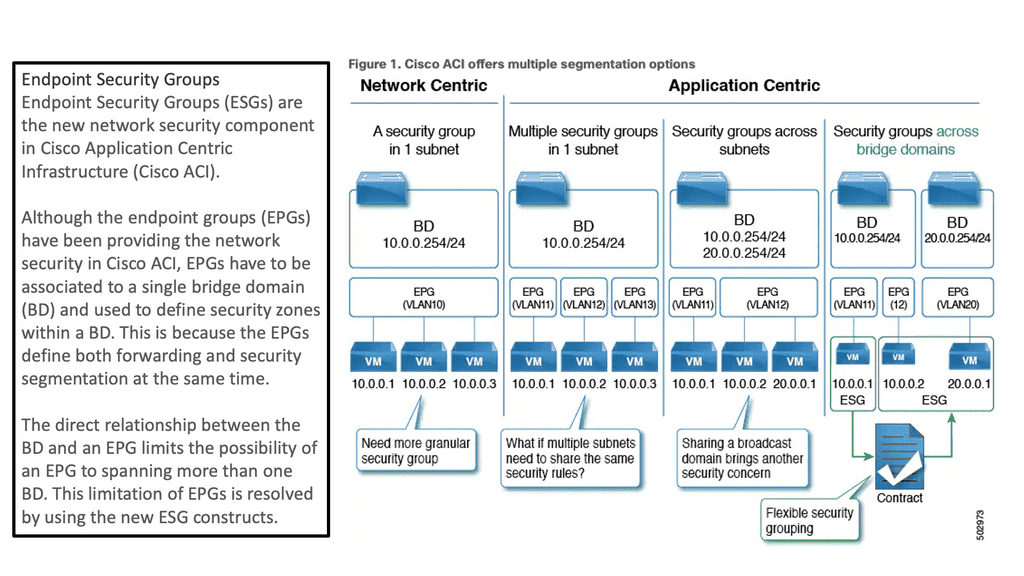
As of ACI 5.0, Endpoint Security Groups (ESGs) are Cisco ACI’s new network security component. Although Endpoint Groups (EPGs) have been providing network security in Cisco ACI, they must be associated with a single bridge domain (BD) and used to define security zones within that BD.
This is because the EPGs define both forwarding and security segmentation simultaneously. The direct relationship between the BD and an EPG limits the possibility of an EPG spanning more than one BD. The new ESG constructs resolve this limitation of EPGs.
Standard Endpoint Groups and Policy Control
As discussed in ACI security, devices are grouped into Endpoint groups, creating ACI segments. This grouping allows the creation of various types of policy enforcement, including access control. Once we have our EPGs defined, we need to create policies to determine how they communicate with each other.
For example, a contract typically refers to one or more ‘filters’ to describe specific protocols & ports allowed between EPGs. We also have ESGs that provide additional security flexibility with more fine-grained ACI segments. Let’s dig a little into the world of contracts in ACI and how these relate to old access control of the past.
Microsegmentation with Cisco ACI adds the ability to group endpoints in existing application EPGs into new microsegment (uSeg) EPGs and configure the network or VM-based attributes for those uSeg EPGs. This enables you to filter with those attributes and apply more dynamic policies.
We can use various attributes to classify endpoints in an EPG called µEPG. Network-based attributes: IP/MAC VM-based attributes: Guest OS, VM name, ID, vnic, DVS, Datacenter.
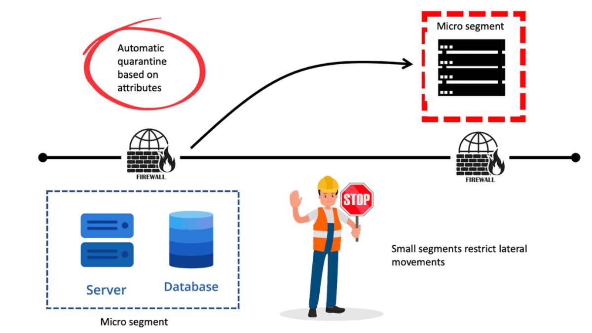
Example: Microsegmentation for Endpoint Quarantine
Let us look at a use case. You might have separate EPGs for web and database servers, each containing both Windows and Linux VMs. Suppose a virus affecting only Windows threatens your network, not the Linux environment.
In that case, you can isolate Windows VMs across all EPGs by creating a new EPG called, for example, “Windows-Quarantine” and applying the VM-based operating systems attribute to filter out all Windows-based endpoints.
This quarantined EPG could have more restrictive communication policies, such as limiting allowed protocols or preventing communication with other EPGs by not having any contract. A microsegment EPG can have a contract or not have a contract.
ACI service graph
ACI and Policy-based redirect: ACI L4-L7 Services
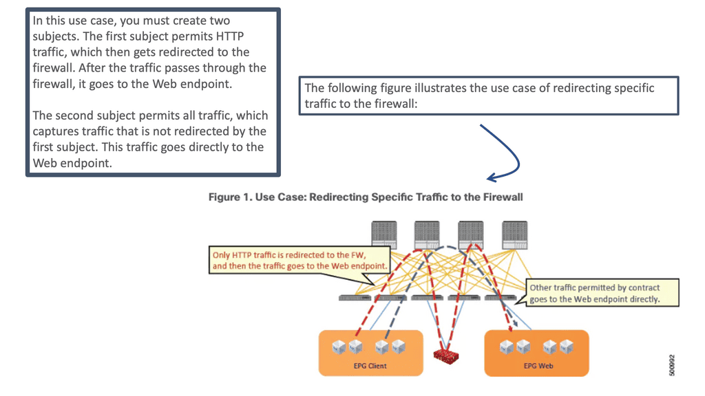
The ACI L4–L7 policy-based redirect (PBR) concept is similar to policy-based routing in traditional networking. In conventional networking, policy-based routing classifies traffic and steers desired traffic from its path to a network device as the next-hop route (NHR). This feature was used in networking for decades to redirect traffic to service devices such as firewalls, load balancers, IPSs/IDSs, and Wide-Area Application Services (WAAS).
In ACI, the PBR concept is similar: You classify specific traffic to steer to a service node by using a subject in a contract. Then, other traffic follows the regular forwarding path, using another subject in the same contract without the PBR policy applied.
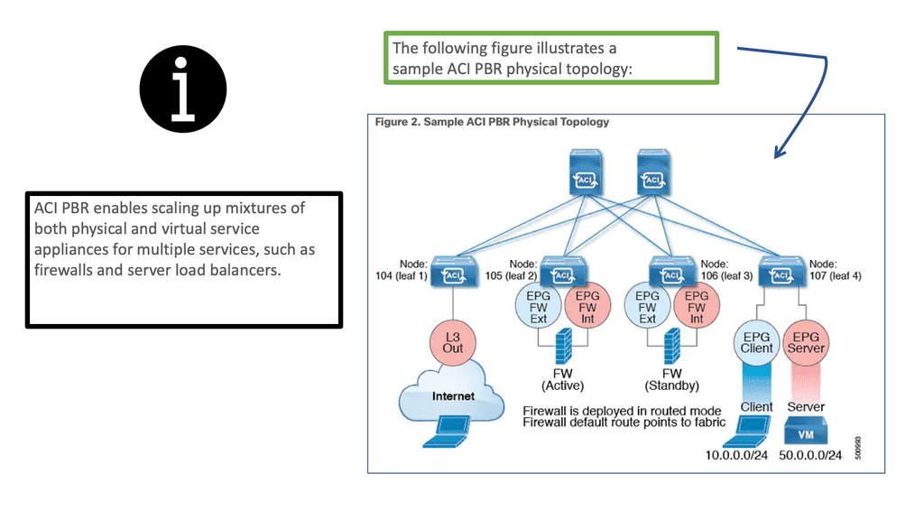
Deploying PBR for ACI L4-L7 services
With ACI policy-based redirect ( ACI L4-L7 services ), firewalls and load balancers can be provisioned as managed or unmanaged nodes without requiring Layer 4 to Layer 7 packages. The typical use cases include providing appliances that can be pooled, tailored to application profiles, scaled quickly, and are less prone to service outages.
In addition, by enabling consumer and provider endpoints to be located in the same virtual routing and forwarding instance (VRF), PBR simplifies the deployment of service appliances. To deploy PBR, you must create an ACI service graph template that uses the route and cluster redirect policies.
After deploying the ACI service graph template, the service appliance enables endpoint groups to consume the service graph endpoint group. Using vzAny can be further simplified and automated. Dedicated service appliances may be required for performance reasons, but PBR can also be used to deploy virtual service appliances quickly.
ACI’s service graph and policy-based redirect (PBR) objects bring advanced traffic steering capabilities to universally utilize any Layer 4 – Layer 7 security device connected in the fabric, even without needing it to be a default gateway for endpoints or part of a complicated VRF sandwich design and VLAN network stitching. So now it has become much easier to implement a Layer 4 – Layer 7 inspection.
You won’t be limited to a single L4-L7 appliance; ACI can chain many of them together or even load balance between multiple active nodes according to your needs. The critical point here is to utilize it universally. The security functions can be in their POD connected to a leaf switch or a pair of leaf switches dedicated to security appliances not located at strategic network points.
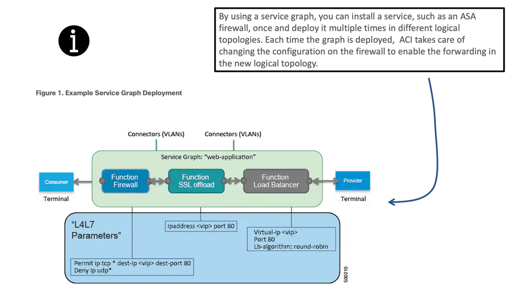
An ACI service graph represents the network using the following elements:
- Function node—A function node represents a function that is applied to the traffic, such as a transform (SSL termination, VPN gateway), filter (firewalls), or terminal (intrusion detection systems). A function within the ACI service graph might require one or more parameters and have one or more connectors.
- Terminal node—A terminal node enables input and output from the service graph.
- Connector—A connector enables input and output from a node.
- Connection—A connection determines how traffic is forwarded through the network.