The ACI Cisco Architecture
The ACI Cisco operates with several standard ACI building blocks. These include Endpoint Groups (EPGs) that classify and group similar workloads; then, we have the Bridge Domains (BD), VRFs, Contract constructs, COOP protocol in ACI, and micro-segmentation. With micro-segmentation in the ACI, you can get granular policy enforcement right on the workload anywhere in the network.
Unlike in the traditional network design, you don’t need to place certain workloads in specific VLANs or, in some cases, physical locations. The ACI can incorporate devices separate from the ACI, such as a firewall, load balancer, or an IPS/IDS, for additional security mechanisms. This enables the dynamic service insertion of Layer 4 to Layer 7 services. Here, we have a lot of flexibility with the redirect option and service graphs.
1: – The ACI Infrastructure
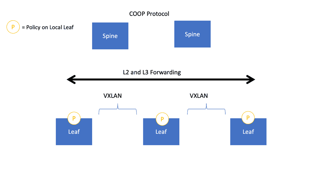
The Cisco ACI architecture is optimized to learn endpoints dynamically with its dynamic endpoint learning functionality. So, we have endpoint learning in the data plane. Therefore, the other devices learn of the endpoints connected to that local leaf switch; the spines have a mapping database that saves many resources on the spine and can optimize the data traffic forwarding. So you don’t need to flood traffic any more. If you want, you can turn off flooding in the ACI fabric. Then, we have an overlay network.
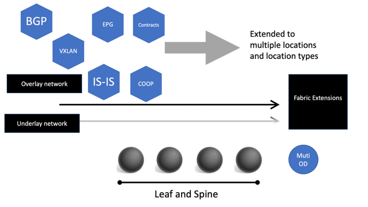
As you know, the ACI network has both an overlay and a physical underlay; this would be a virtual underlay in the case of Cisco Cloud ACI. The ACI uses VXLAN, the overlay protocol that rides on top of a simple leaf and spine topology, with standards-based protocols such as IS-IS and BGP for route propagation.
2: – ACI Networks
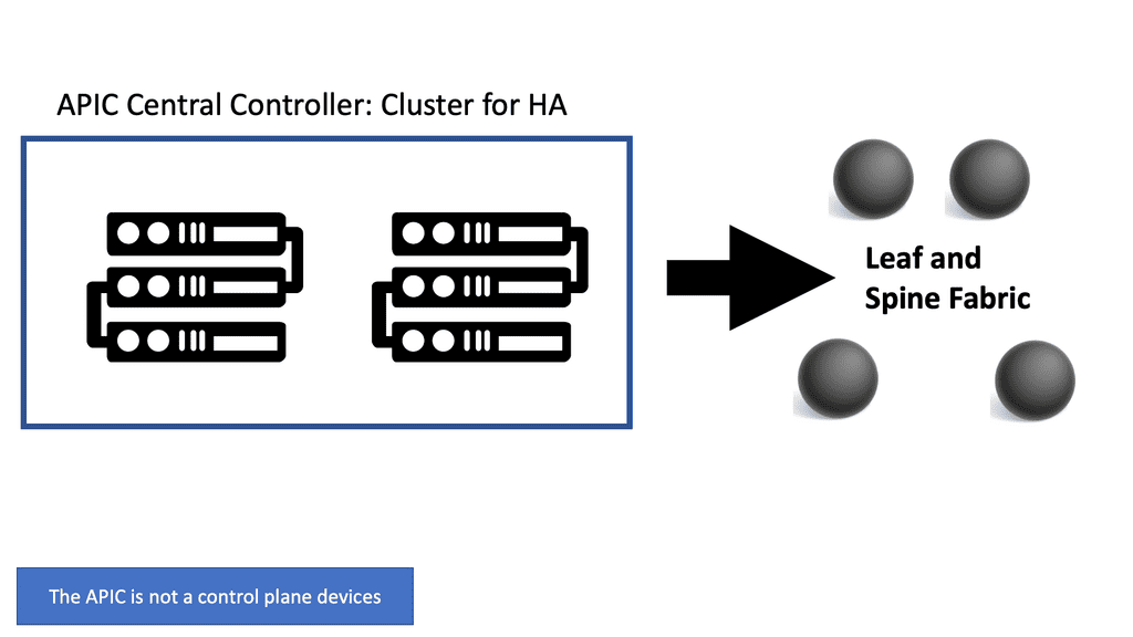
ACI Networks also introduces the concept of the Application Policy Infrastructure Controller (APIC), which acts as the central point of control for the network. The APIC allows administrators to define and enforce network policies, monitor performance, and troubleshoot issues.
In addition to network virtualization and policy management, ACI Cisco offers a range of other features. These include integrated security, intelligent workload placement, and seamless integration with other Cisco products and technologies.
3: – COOP Protocol in ACI
The spine proxy receives mapping information (location and identity) via the Council of Oracle Protocol (COOP). Using Zero Message Queue (ZMQ), leaf switches forward endpoint address information to spine switches. As part of COOP, the spine nodes maintain a consistent copy of the endpoint address and location information and maintain the distributed hash table (DHT) database for mapping endpoint identity to location.
4: – Micro-segmentation
Integrated security is achieved through micro-segmentation, which allows administrators to define fine-grained security policies at the application level. This helps to prevent the lateral movement of threats within the network and provides better protection against attacks.
Intelligent workload placement ensures that applications are placed in the most appropriate locations within the network based on their specific requirements. This improves application performance and resource utilization.
Data Center Network Challenges
Let us examine well-known data center challenges and how the Cisco ACI network solves them.
Challenge: Traditional Complicated Topology
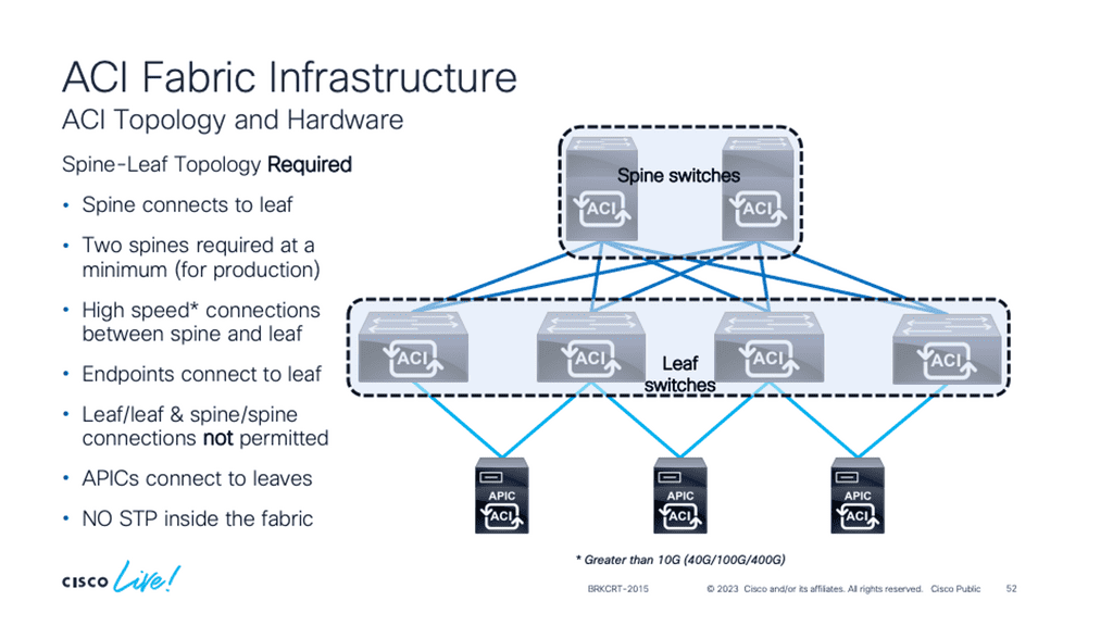
A traditional data center network design usually uses core distribution access layers. When you add more devices, this topology can be complicated to manage. Cisco ACI uses a simple spine-leaf topology, wherein all the connections within the Cisco ACI fabric are from leaf-to-spine switches, and a mesh topology is between them. There is no leaf-to-leaf and no spine-to-spine connectivity.
Required: How ACI Cisco overcomes this
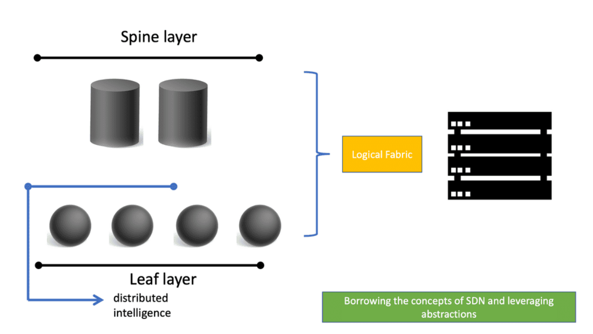
The Cisco ACI architecture uses the leaf-spine, consisting of a two-tier “fat tree” topology with equidistant bandwidths. The leaf layer connects to the physical and virtual workloads and network services, while the spine layer is the transport layer that interconnects the leaves.
Challenge: Oversubscription
Oversubscription generally means potentially requiring more resources from a device, link, or component than are available. Therefore, the oversubscription ratio must be examined at multiple aggregation points in the design, including the line card to switch fabric bandwidth and the switch fabric input to uplink bandwidth.
Oversubscription Example
Let’s look at a typical 2-layer network topology with access switches and a central core switch. The access switches have 24 user ports and one uplink port connected to the core switch. Each access switch has 24 1Gb user ports and a 10Gb uplink port. So, in theory, if all the user ports are transmitted to a server simultaneously, they would require 24 GB of bandwidth (24 x 1 GB).
However, the uplink port is only 10, limiting the maximum bandwidth to all the user ports. The uplink port is oversubscribed because the theoretical required bandwidth (24Gb) exceeds the available bandwidth (10Gb). Oversubscription is expressed as a ratio of bandwidth needed to available bandwidth. In this case, it’s 24Gb/10Gb or 2.
Challenge: Varying bandwidths
We have layers of oversubscription with the traditional core, distribution, and access designs. We have oversubscribed at the access, distribution, and core layers. The cause of this will give varying bandwidth to endpoints if they want to communicate with an endpoint that is near or an endpoint that is far away. With this approach, endpoints on the same switch will have more bandwidth than two endpoints communicating across the core layer.
Users and application owners don’t care about networks; they want to place their workload wherever the computer is and want the same BW regardless of where you put it. However, with traditional designs, the bandwidth available depends on where the endpoints are located.
Required: How ACI Cisco overcomes this
The ACI leaf and spine have equidistant endpoints between any two endpoints. So if any two servers have the same bandwidths, which is a big plus for data center performance, then it doesn’t matter where you place the workload, which is a big plus for virtualized workloads. This gives you unlimited workload placement.
Challenge: Lack of portability
Applications are built on top of many building blocks. We use contracts such as VLANs, IP addresses, and ACLs to create connectivity. We use these constructs to create and translate the application requirements to the network infrastructure. These constructs are hardened into the network with configurations applied before connectivity.
These configurations are not very portable. It’s not that they were severely designed; they were never meant to be portable. Location Independent Separation Protocol (LISP) did an excellent job making them portable. However, they are hard-coded for a particular requirement at that time. Therefore, if we have the exact condition in a different data center location, we must reconfigure the IP address, VLANs, and ACLs.
Required: How ACI Cisco overcomes this
An application refers to a set of networking components that provides connectivity for a given set of workloads. These workloads’ relationship is what ACI calls an “application,” and the connection is expressed by what ACI calls an application network profile. With a Cisco ACI design, we can create what is known as Application Network Profiles (ANPs).
The ANP expresses the relationship between the application and its communications. It is a configuration template used to express the relationship between segments. The ACI then translates those relationships into networking constructs such as VLANs, VXLAN, VRF, and IP addresses that the devices in the network can then implement.
Challenge: Issues with ACL
The traditional ACL is very tightly coupled with the network topology, and anything that is tightly coupled will kill agility. It is configured on a specific ingress and egress interface and pre-set to expect a particular traffic flow. These interfaces are usually at demarcation points in the network. However, many other points in the network could do so with security filtering.
Required: How ACI Cisco overcomes this
The fundamental security architecture of the Cisco ACI design follows an allow-list model, where we explicitly define what traffic should be permitted. A contract is a policy construct used to describe communication between EPGs. Without a contract, no unicast communication is possible between those EPGs unless the VRF is configured in “unenforced” mode or those EPGs are in a preferred group.
A contract is not required to communicate between endpoints in the same EPG (although transmission can be prevented with intra-EPG isolation or intra-EPG contract). We have a different construct for applying the policy in ACI. We use the contract construct, and within the contract construct, we have subjects and filters that specify how endpoints are allowed to communicate.
These managed objects are not tied to the network’s topology because they are not applied to a specific interface. Instead, the contracts are used in the intersection between EPGs. They represent rules the network must enforce irrespective of where these endpoints are connected.
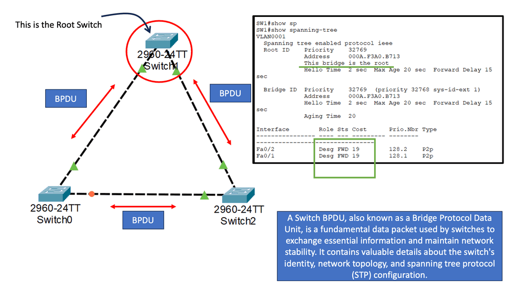
Challenge: Issues with Spanning Tree Protocol (STP)
A significant shortcoming of STP is that it is a brittle failure mode that can bring down entire data centers or campus networks when something goes wrong. Though modifications and enhancements have addressed some of these risks, this has happened at the cost of technical debt in design and maintenance.
When you think about how this works, we have a BPDU that acts as a HELLO mechanism. When we stop receiving the BPDUs and the link stays up, we forward all the links. So, spanning Tree Protocol causes outages.
Required: How ACI Cisco overcomes this
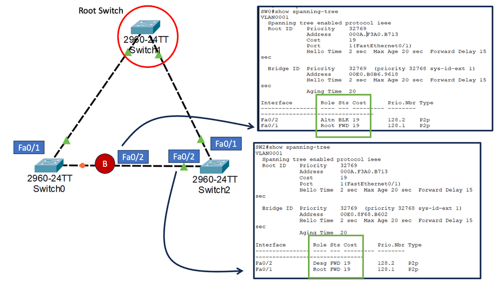
The Cisco ACI does not run Spanning Tree Protocol natively, meaning the ACI control plane does not run STP. Inside the fabric, we are running IS-IS as the interior routing protocol. If we stop receiving, we don’t go into an all-forwarding state with IS-IS. As we have IP reachability between Leaf and Spine, we don’t have to block ports and see actual traffic flows that are not the same as the physical topology.
Within the ACI fabric, we have all the advantages of layer three networks, which are more robust and predictable than with an STP design. With ACI, we don’t rely on SPT for the topology design. Instead, the ACI uses ECMP for layer 2 and Layer 3 forwarding. We can use ECMP because we have routed links between the leaves and spines in the ACI fabric.
Challenge: Core-distribution design
The traditional design uses VLANs to segment Layer 2 boundaries and broadcast domains logically. VLANs use network links inefficiently, resulting in rigid device placement. We also have a cap on the number of VLANs we can create. Some applications require that you need Layer 2 adjacencies.
For example, clustering software requires Layer 2 adjacency between source and destination servers. However, if we are routing at the access layer, only servers connected to the same access switch with the same VLANs trunked down would be Layer 2-adjacent.
Required: How ACI Cisco overcomes this
VXLAN solves this dilemma in ACI by decoupling Layer 2 domains from the underlying Layer 3 network infrastructure. With ACI, we are using the concepts of overlays to provide this abstract. Isolated Layer 2 domains can be connected over a Layer 3 network using VXLAN. Packets are transported across the fabric using Layer 3 routing.
This paradigm fully supports layer 2 networks. Large layer-2 domains will always be needed, for example, for VM mobility, clusters that don’t or can’t use dynamic DNS and non-IP traffic, and broadcast-based intra-subnet communication.
**Cisco ACI Architecture: Leaf and Spine**
The fabric is symmetric with a leaf and spine design, and we have central bandwidth. Therefore, regardless of where a device is connected to the fabric, it has the same bandwidth as every other device connected to the same fabric. This removes the placement restrictions that we have with traditional data center designs. A spine-leaf architecture is a data center network topology that consists of two switching layers—a spine and a leaf.
The leaf layer comprises access switches that aggregate server traffic and connect directly to the spine or network core. Spine switches interconnect all leaf switches in a full-mesh topology.
With low latency east-west traffic, optimized traffic flows are imperative for performance, especially for time-sensitive or data-intensive applications. A spine-leaf architecture aids this by ensuring traffic is always the same number of hops from its next destination, so latency is lower and predictable.
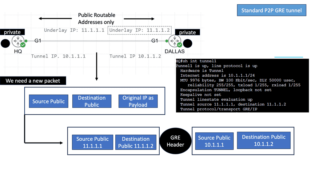
Displaying a VXLAN tunnel
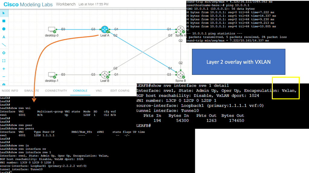
We have expanded the original design and added VXLAN. We are creating a Layer 2 network, specifically, a Layer 2 overlay over a Layer 3 routed core. The Layer 2 extension allows the hosts, desktop 0 and desktop 1, to communicate over the Layer 2 overlay that VXLAN creates.
The hosts’ IP addresses are 10.0.0.1 and 10.0.0.2, which are not reachable via the Leaf switches. The Leaf switches cannot ping these. Consider the Leaf and Spine switches a standard Layer 3 WAN or network for this lab. So, we have unicast connectivity over the WAN.
The only IP routing addition I have added is the new loopback addresses on Leafs 1 and 2, of 1.1.1.1/32 and 2.2.2.2/32, used for ingress replication for VXLAN. Remember that the ACI is one of many products that use Layer 2 overlays. VXLAN can be used as a Layer 2 DCI.
Notice below I am running a ping from desktop 0 to the corresponding desktop. These hosts are in the 10.0.0.0/8 range, and the core does not know these subnets. I’m also running a packet capture on the link Gi1 connected to Leaf A.
Notice the source and destination are 1.1.1.1 and 2.2.2.2.2, which are the VTEPs. The IMCP traffic is encapsulated into UDP port 1024, explicitly set in the confirmation as the VXLAN port to use.
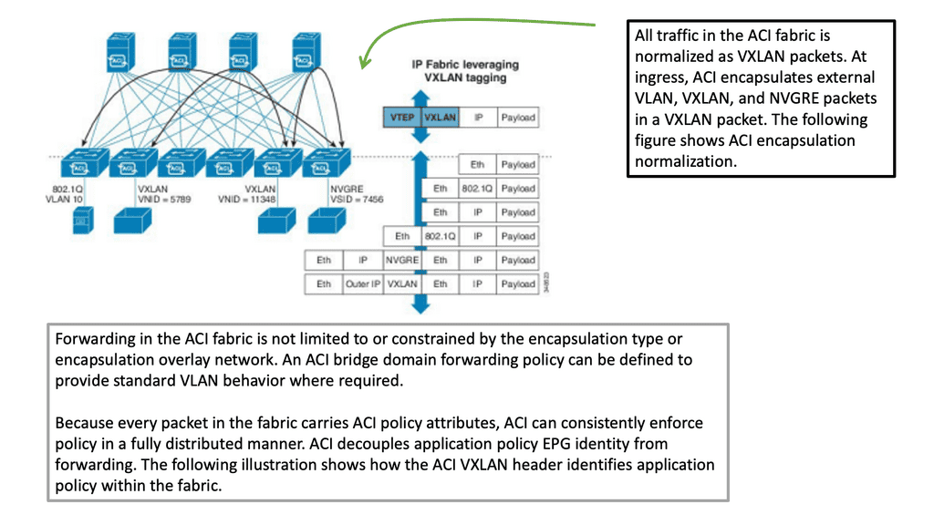
ACI Network: VXLAN transport network
In a leaf-spine ACI fabric, we have a native Layer 3 IP fabric that supports equal-cost multi-path (ECMP) routing between any two endpoints in the network. Using VXLAN as the overlay protocol allows any workload to exist anywhere in the network.
We can have physical and virtual machines in the same logical layer 2 domain while running layer 3 routing to the top of each rack. Thus, we can connect several endpoints to each leaf, and for one endpoint to communicate with another, we use VXLAN.
So, the transport of the ACI fabric is carried out with VXLAN. The ACI encapsulates traffic with VXLAN and forwards the data traffic across the fabric. Any policy that needs to be implemented gets applied at the leaf layer. All traffic on the fabric is encapsulated with VXLAN. This allows us to support standard bridging and routing semantics without the standard location constraints.
Council of Oracle Protocol
COOP protocol in ACI and the ACI fabric
The fabric appears to the outside as one switch capable of forwarding Layers 2 and 3. In addition, the fabric is a Layer 3 network routed network and enables all links to be active, providing ECMP forwarding in the fabric for both Layer 2 and Layer 3. Inside the fabric, we have routing protocols such as BGP; we also use Intermediate System-to-Intermediate System Protocol (IS-IS) and Council of Oracle Protocol (COOP) for all forwarding endpoint-to-endpoint communications.
The COOP protocol in ACI communicates the mapping information (location and identity) to the spine proxy. A leaf switch forwards endpoint address information to the spine switch ‘Oracle’ using Zero Message Queue (ZMQ). The COOP protocol in ACI is something new to data centers. The Leaf switches use COOP to report local station information to the Spine (Oracle) switches.
COOP protocol in ACI
Let’s look at an example of how the COOP protocol in ACI works. We have a Leaf that learns of a host. The Leaf reports this information—let’s say it knows Host B—and sends it to one of the Spine switches chosen randomly using the Council Of Oracle Protocol.
The Spine switch then relays this information to all the other Spines in the ACI fabric so that every Spine has a complete record of every single endpoint. The Spines switches record the information learned via the COOP in the Global Proxy Table, which resolves unknown destination MAC/IP addresses when traffic is sent to the Proxy address.
COOP database.
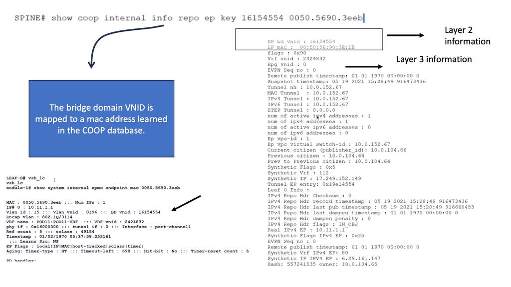
So, we know that the Spine has a COOP database of all endpoints in the fabric. Council of Oracle Protocol (COOP) is used to communicate the mapping information (location and identity) to the spine proxy. A leaf switch forwards endpoint address information to the spine switch ‘Oracle’ using Zero Message Queue (ZMQ).
The command: Show coop internal info repo key allows us to verify that the endpoint is in the COOP database using the BD VNID of 16154554 mapped to the MAC address of 0050.5690.3eeb. With this command, you can also see the tunnel next hop and IPv4 and IPv6 addresses tied to this MAC address.
**The fabric constructs**
The ACI Fabric contains several new network constructs specific to ACI that enable us to abstract much of the complexity we had with traditional data center designs. These new concepts are ACI’s Endpoint Groups, Contracts, Bridge Domains, and COOP protocol.
In addition, we have a distributed Layer 3 Anycast gateway function that ensures optimal Layer 3 and Layer 2 forwarding. We also have original constructs you may have used, such as VRFs. The Layer 3 Anycast feature is popular and allows flexible placement of the default gateway, which is suited for agile designs.
Related: For pre-information, you may find the following helpful:
ACI Infrastructure
Key components that make up the ACI Cisco architecture. By understanding these components, network administrators and IT professionals can harness the power of ACI to optimize their data center operations.
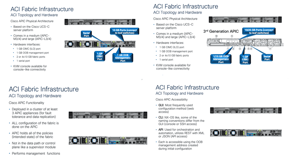
1. Application Policy Infrastructure Controller (APIC):
The cornerstone of the Cisco ACI architecture is the Application Policy Infrastructure Controller (APIC). APIC is the central management and policy engine for the entire ACI fabric. It provides a single point of control, enabling administrators to define and enforce policies that govern the behavior of applications and services within the data center. APIC offers a user-friendly interface for policy configuration, monitoring, and troubleshooting, making it an essential component for managing the ACI fabric.
2. Spine Switches:
Spine switches form the backbone of the ACI fabric. These high-performance switches provide connectivity between leaf switches and facilitate east-west traffic within the fabric. Spine switches operate at Layer 3 and use routing protocols to efficiently distribute traffic across the fabric. With the ability to handle massive amounts of data, spine switches ensure high-speed connectivity and optimal performance in the ACI environment.
3. Leaf Switches:
Leaf switches act as the access layer switches in the ACI fabric. They connect directly to the endpoints, such as servers, storage devices, and other network devices, and serve as the entry and exit points for traffic entering and leaving the fabric. Leaf switches provide Layer 2 connectivity for endpoint devices and Layer 3 connectivity for communication between endpoints within the fabric. They also play a crucial role in implementing policy enforcement and forwarding traffic based on predefined policies.
**Example: Cisco ACI & IS-IS**
Cisco ACI under the covers runs ISIS. The ISIS routing protocol is an Interior Gateway Protocol (IGP) that enables routers within a network to exchange routing information and make informed decisions on the best path to forward packets. It operates at the OSI model’s Layer 2 (Data Link Layer) and Layer 3 (Network Layer).
ISIS organizes routers into logical groups called areas, simplifying network management and improving scalability. It allows for hierarchical routing, reducing the overhead of exchanging routing information across large networks.
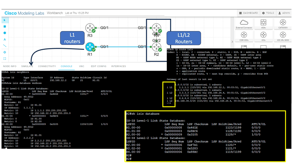
**Note: IS-IS Parameters**
Below, we have four routers. R1 and R2 are in area 12, and R3 and R4 are in area 34. R1 and R3 are intra-area routers so that they will be configured as level 1 routers. R2 and R4 form the backbone so that these routers will be configured as levels 1-2.
Network administrators need to configure ISIS parameters on each participating router to implement ISIS. These parameters include the router’s ISIS system ID, area assignments, and interface settings. ISIS uses the reliable transport protocol (RTP) to exchange routing information between routers.
4. Application Network Profiles (ANPs):
Application Network Profiles (ANPs) are a key Cisco ACI policy model component. They define the policies and configurations required for specific applications or application groups and encapsulate all the necessary information, including network connectivity, quality of service (QoS) requirements, security policies, and service chaining.
By associating endpoints with ANPs, administrators can easily manage and enforce consistent policies across the ACI fabric, simplifying application deployment and ensuring compliance.
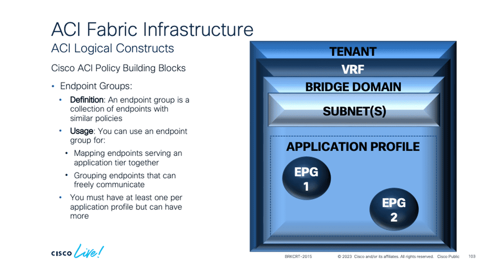
5. Endpoint Groups (EPGs):
Endpoint Groups (EPGs) are logical containers that group endpoints with similar network requirements. EPGs provide a way to define and enforce policies at a granular level—endpoints within an EPG share standard policies, such as security, QoS, and network connectivity.
This grouping allows administrators to apply policies consistently to specific endpoints, regardless of their physical location within the fabric. EPGs enable seamless application mobility and simplify policy enforcement within the ACI environment.
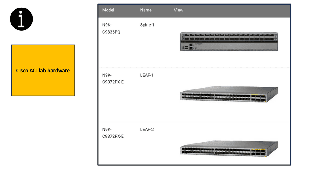
**Specific ACI Cisco architecture**
In some of the lab guides in this blog post, we are using the following hardware from a rack rental from Cloudmylabs. Remember that the ACI Fabric is built on the Nexus 9000 Product Family.
The Cisco Nexus 9000 Series Switches are designed to meet the increasing demands of modern networks. With high-performance capabilities, these switches deliver exceptional speeds and low latency, ensuring smooth and uninterrupted data flow. They support high-density 10/25/40/100 Gigabit Ethernet interfaces, allowing businesses to scale and adapt to growing network requirements.
Enhanced Security:
The Cisco Nexus 9000 Series Switches offer comprehensive security features to protect networks from evolving threats. They leverage Cisco TrustSec technology, which provides secure access control, segmentation, and policy enforcement. With integrated security features, businesses can mitigate risks and safeguard critical data, ensuring peace of mind.
Application Performance Optimization:
To meet the demands of modern applications, the Cisco Nexus 9000 Series Switches are equipped with advanced features that optimize application performance. These switches support Cisco Tetration Analytics, which provides deep insights into application behavior, enabling businesses to enhance performance, troubleshoot issues, and improve efficiency.
Cisco ACI Simulator:
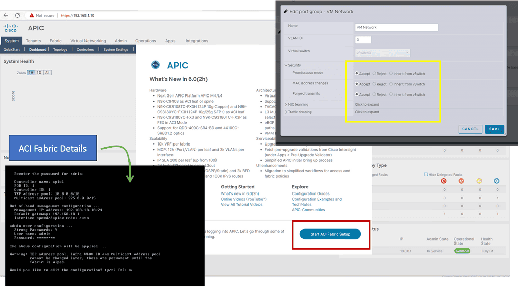
Below is a screenshot from Cisco ACI similar to the one below. At the start, you will be asked for the details of the fabric. Remember that once you set the out-of-band management address for the API, you need to change the port group settings on the ESXi VM network. If you don’t change “Promiscuous mode, MAC address changes, and Forged Transmits,” you cannot access the UI from your desktop.
Leaf and spine design
Network Design Methodology
Leaf and spine architecture is a network design methodology commonly used in data centers. It provides a scalable and resilient infrastructure that can handle the increasing demands of modern applications and services. The term “leaf and spine” refers to the physical and logical structure of the network.
In leaf and spine architecture, the network is divided into two main layers: the leaf and spine layers. The leaf layer consists of leaf switches connected to the servers or endpoints in the data center. These leaf switches act as the access points for the servers, providing high-bandwidth connectivity and low-latency communication.
The spine layer, on the other hand, consists of spine switches that connect the leaf switches. The spine switches provide high-speed and non-blocking interconnectivity between the leaf switches, forming a fully connected fabric. This allows for efficient and predictable traffic patterns, as any leaf switch can communicate directly with any other leaf switch through the spine layer.
ACI Cisco with leaf and spine.
The following lab guide has a leaf and spine ACI design that includes 2 leaf switches acting as the leaf layer where the workloads connect. Then, we have a spine attached to the leaf. When the ACI hardware installation is done, all Spines and Leafs are linked and powered up. Once the basic configuration of APIC is completed, the Fabric discovery process starts working.
Note: IFM process
In the discovery process, ACI uses the Intra-Fabric Messaging (IFM) process in which APIC and nodes exchange heartbeat messages.
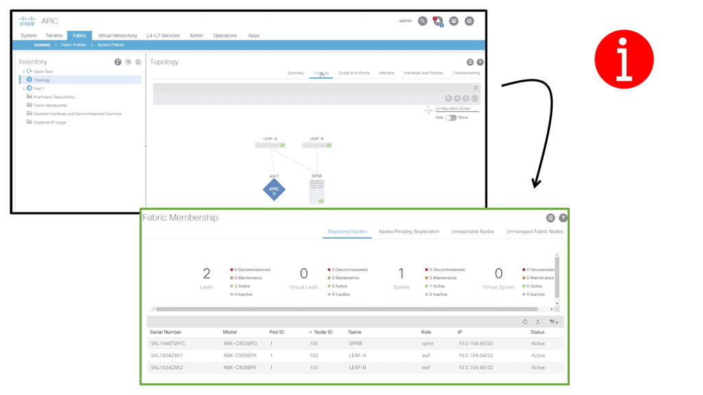
The process used by the APIC to push policy to the fabric leaf nodes is called the IFM Process. ACI Fabric discovery is completed in three stages. The leaf node directly connected to the APIC is discovered in the first stage. The second discovery stage brings in the spines connected to that initial leaf where APIC was connected. The third stage involves discovering the cluster’s other leaf nodes and APICs.
The fabric membership diagram below shows the inventory, including serial number, Pod, Node ID, Model, Role, Fabric IP, and Status. Cisco ACI consists of the following hardware components: APIC Controller Spine Switches and Leaf Switches.
Analysis: Overlay based on VXLAN
Cisco ACI uses an overlay based on VXLAN to virtualize physical infrastructure. Like most overlays, this overlay requires the data path at the network’s edge to map from the tenant end-point address in the packet, otherwise referred to as its identifier, to the endpoint’s location, also known as its locator. This mapping occurs in a tunnel endpoint (TEP) function called VXLAN (VTEP).
VTEP Addressing
The VTEP addresses are displayed in the INFRASTRUCTURE IP column. The TEP address pool 10.0.0.0/16 has been configured on the Cisco APIC using the initial setup dialog. The APIC assigns the TEP addresses to the fabric switches via DHCP, so the infrastructure IP addresses in your fabric will differ from the figure.
This configuration is perfectly valid for a Lab but not good for a production environment. The minimum physical fabric hardware for a production environment includes two spines, two leaves, and three APICs.In addition to discovering and configuring the Fabric and applying the Tenant design, the following functionality can be configured:
- Routing at Layer 3
- Connecting a legacy network at layer 2
- Virtual Port Channels at Layer 2
Note: Border Leaf
A note about Border Leafs: ACI fabrics often use this designation along with “Compute Leafs” and “Storage Leafs.” Border Leaf is merely a convention for identifying the leaf pair that hosts all external connectivity external to the fabric (Border Leaf) or the leaf pair that hosts host connectivity (Compute Leaf).
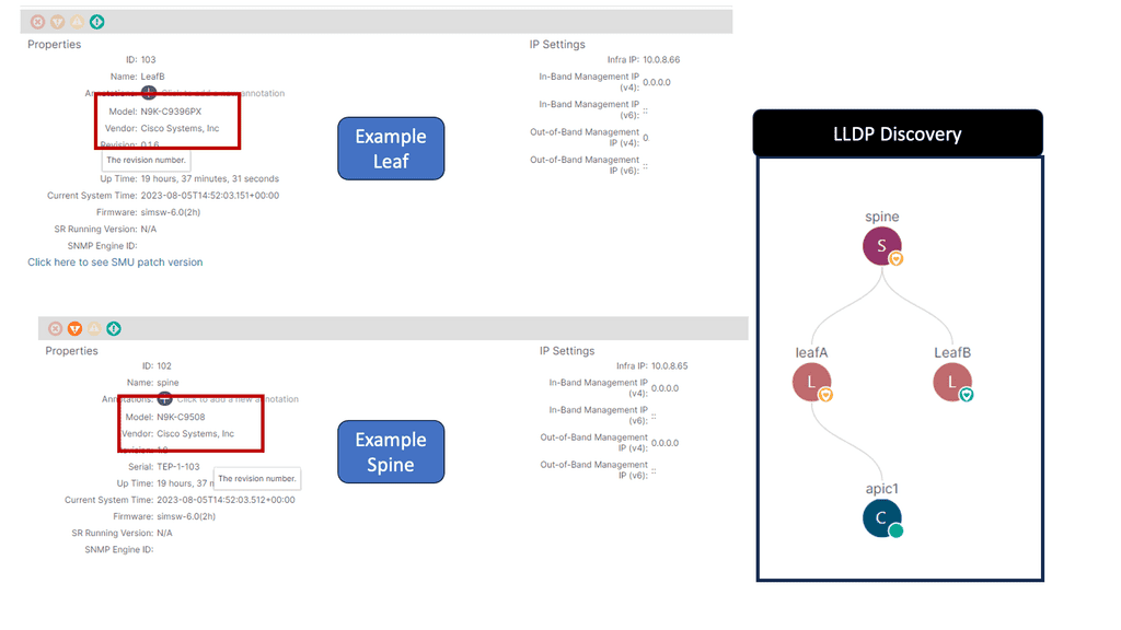
Note: The Link Layer Discovery Protocol (LLDP)
LLDP is responsible for discovering directly adjacent neighbors. When run between the Cisco APIC and a leaf switch, it precedes three other processes: Tunnel endpoint (TEP) IP address assignment, node software upgrade (if necessary), and the intra-fabric messaging (IFM) process, which the Cisco APIC uses to push policy to the leaves.
Leaf and Spine: Traffic flows
The leaf and spine network topology is suitable for east-to-west network traffic and comprises leaf switches to which the workloads connect and spine switches to which the leaf switches connect. The spines have a simple role and are geared around performance, while all the intelligence is distributed to the edge of the network, where the leaf layers sit.
This allows engineers to move away from managing individual devices and more efficiently manage the data center architecture with policy. In this model, the Application Policy Infrastructure Controller (APIC) controllers can correlate information from the entire fabric.
**Understanding Leaf and Spine Traffic Flow**
In a leaf and spine architecture, traffic flow follows a structured path. When a device connected to a leaf switch wants to communicate with another device, the traffic is routed through the spine switch to the destination leaf switch. This approach minimizes the hops required for data transmission and reduces latency. Additionally, traffic can be evenly distributed since every leaf switch is connected to every spine switch, preventing congestion and bottlenecks.
**ACI Cisco with leaf and spine**
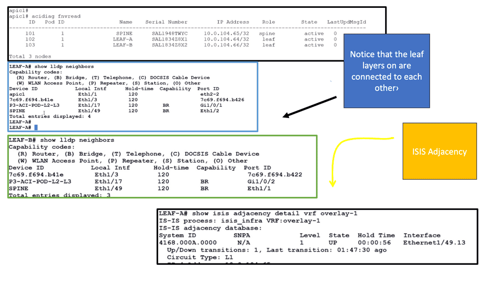
In the following lab guide, we continue to verify the ACI leaf and spine. To check the ACI fabric, we can run the diagnostic tool Acidiag fnvread. It is also recommended that the LLDP and ISIS adjacencies be checked. With a leaf and spine design, the leaf layer does not connect, and we can see this with the LLDP and ISIS adjacency information below.
Leaf and Spine Switch Functions
Based on a two-tier (spine and leaf switches) or three-tier (spine switch, tier-1 leaf switch, and tier-2 leaf switch) architecture, Cisco ACI switches provide the following functions:
What are Leaf Switches?
Leaf switches connect between end devices, servers, and the network fabric. They are typically deployed in leaf-spine network architecture, connecting directly to the spine switches. Leaf switches provide high-speed, low-latency connectivity to end devices within a data center network.
Functionalities of Leaf Switches:
1. Aggregation: Leaf switches aggregate traffic from multiple servers and sends it to the spine switches for further distribution. This aggregation helps reduce the network’s complexity and enables efficient traffic flow.
2. High-density Port Connectivity: Leaf switches are designed to provide a high-density port connectivity environment, allowing multiple devices to connect simultaneously. This is crucial in data centers where numerous servers and devices must be interconnected.
These devices have ports connected to classic Ethernet devices, such as servers, firewalls, and routers. In addition, these leaf switches provide the VXLAN Tunnel Endpoint (VTEP) function at the edge of the fabric. In Cisco ACI terminology, IP addresses representing leaf switch VTEPs are called Physical Tunnel Endpoints (PTEPs). The leaf switches route or bridge tenant packets and applies network policies.
What are Spine Switches?
Spine switches, also known as spine or core switches, are high-performance switches that form the backbone of a network. They play a vital role in data centers and large enterprise networks and facilitate the seamless data flow between various leaf switches.
These devices interconnect leaf switches and can also connect Cisco ACI pods to IP networks or WAN devices to build a Cisco ACI Multi-Pod fabric. In addition to mapping entries between endpoints and VTEPs, spine switches also store proxy entries between endpoints and VTEPs. Leaf switches are connected to spine switches within a pod, and spine switches are connected to leaf switches.
No direct connection between tier-1 leaf switches, tier-2 leaf switches, or spine switches is allowed. If you incorrectly cable spine switches to each other or leaf switches in the same tier to each other, the interfaces will be disabled.
BGP Route Reflection
Under the cover, Cisco ACI works with BGP Route-Reflection. BGP Route Reflection creates a hierarchy of routers within the ACI fabric. At the top of the hierarchy is a Route-Reflector (RR), a central point for collecting routing information from other routers within the fabric. The RR then reflects this information to other routers, ensuring that every router in the network has a complete view of the routing table.
The ACI uses MP-BGP protocol to distribute external Network subnets or prefixes inside the ACI fabric. To create an MP-BGP route reflector, we must select two Spines acting as Route Reflectors and make an iBGP Neighbourship to all other leaves.


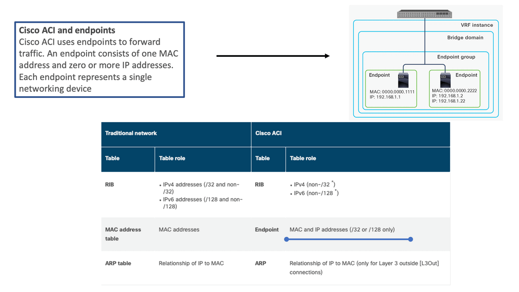
ACI Cisco and endpoints
In a traditional network, three tables are used to maintain the network addresses of external devices: a MAC address table for Layer 2 forwarding, a Routing Information Base (RIB) for Layer 3 forwarding, and an ARP table for the combination of IP addresses and MAC addresses. Cisco ACI, however, maintains this information differently, as shown below.
What is ACI Endpoint Learning?
ACI endpoint learning refers to discovering and monitoring the network endpoints within an ACI fabric. Endpoints include devices, virtual machines, physical servers, users, and applications. Network administrators can make informed decisions regarding network policies, security, and traffic optimization by gaining insights into these endpoints’ location, characteristics, and behavior.
How Does ACI Endpoint Learning Work?
ACI fabric leverages a distributed, controller-based architecture to facilitate endpoint learning. When an endpoint is connected to the fabric, ACI utilizes various mechanisms to gather information about it. These mechanisms include Address Resolution Protocol (ARP) snooping, Link Layer Discovery Protocol (LLDP), and even integration with hypervisor-based systems.
Once an endpoint is detected, ACI Fabric builds a comprehensive endpoint database called the Endpoint Group (EPG). This database contains vital information such as MAC addresses, IP addresses, VLANs, and associated policies. By continuously monitoring and updating this database, ACI ensures real-time visibility and control over the network endpoints.
Implementation Endpoint Learning Considerations:
To leverage the benefits of ACI endpoint learning, organizations need to consider a few key aspects:
1. Infrastructure Design: A well-designed ACI fabric with appropriate leaf and spine switches is crucial for efficient endpoint learning. Proper VLAN and subnet design should be implemented to ensure accurate endpoint identification and classification.
2. Endpoint Group (EPG) Definition: Defining and associating EPGs with appropriate policies is essential. EPGs help categorize endpoints based on their characteristics, allowing for granular policy enforcement and simplified management.
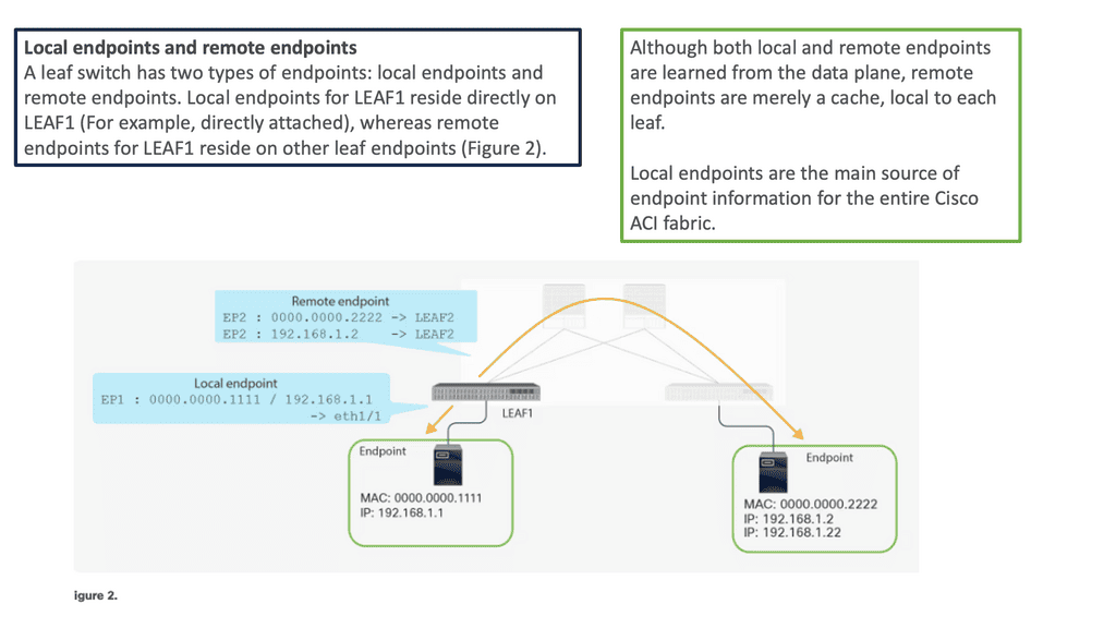
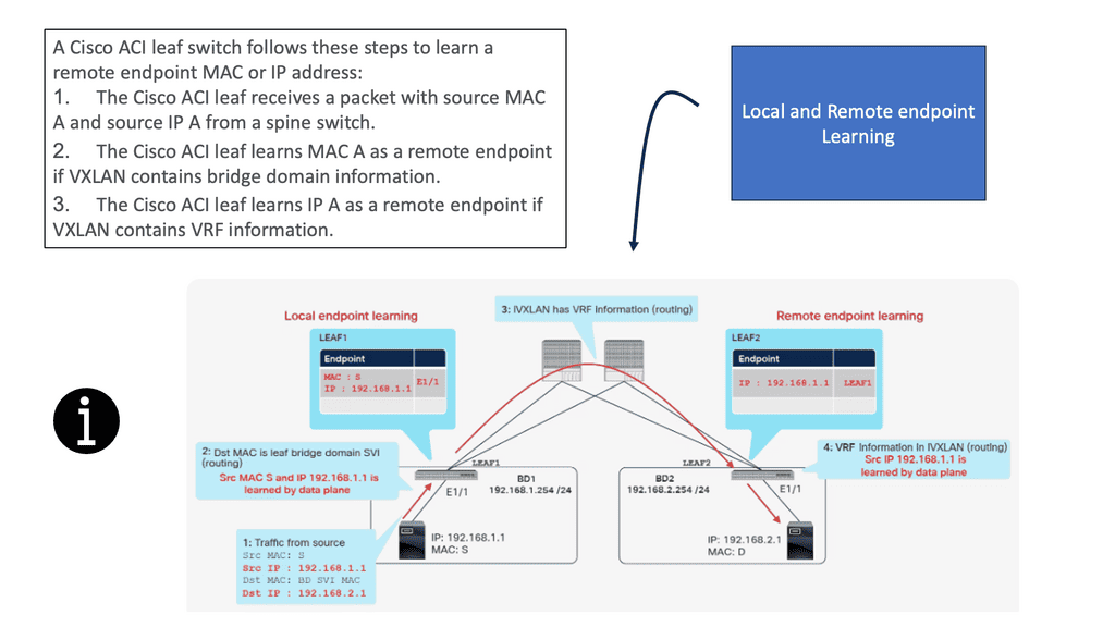
Forwarding Behavior. The COOP database
Local and remote endpoints are learned from the data plane, but remote endpoints are local caches. Cisco ACI’s fabric relies heavily on local endpoints for endpoint information. A leaf is responsible for reporting its local endpoints to the Council Of Oracle Protocol (COOP) database located on each spine switch, which implies that all endpoint information in the Cisco ACI fabric is stored there.
Each leaf does not need to know about all the remote endpoints to forward packets to the remote endpoints because this database is accessible. When a leaf does not know about a remote endpoint, it can still forward packets to spine switches. This forwarding behavior is called spine proxy.
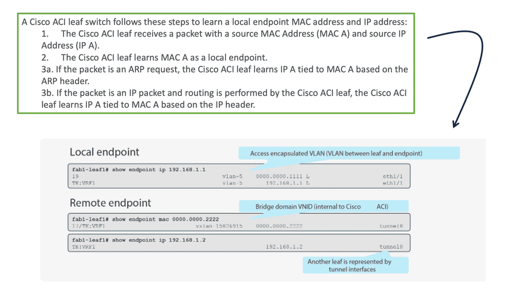
In a traditional network environment, switches rely on the Address Resolution Protocol (ARP) to map IP addresses to MAC addresses. However, this approach becomes inefficient as the network scales, resulting in increased network traffic and complexity. Cisco ACI addresses this challenge by utilizing local endpoint learning, a more intelligent and efficient method of mapping MAC addresses to IP addresses.
ACI Cisco: The Main Features
We are experiencing many changes right now that are impacting almost every aspect of IT. Applications are changing immensely, and we see their life cycles broken into smaller windows as they become less structured. In addition, containers and microservices are putting new requirements on the underlying infrastructure, such as the data centers they live in. This is one of the main reasons why a distributed system, including a data center, is better suited for this environment.
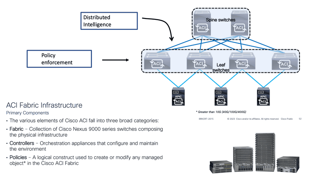
Distributed system/Intelligence at the edge
Like all networks, the Cisco ACI network still has a control and data plane. From the control and data plane perspective, the Cisco ACI architecture is still a distributed system. Each switch has intelligence and knows what it needs to do—one of the differences between ACI and traditional SDN approaches that try to centralize the control plane. If you try to centralize the control plan, you may hit scalability limits, not to mention a single point of failure and an avenue for bad actors to penetrate.
Two large core devices
If we examine the traditional data center architecture, intelligence is often in two central devices. You could have two large core devices. What the network used to control and secure has changed dramatically with virtualization via hypervisors. We’re seeing faster change with containers and microservices being deployed more readily.
As a result, an overlay networking model is better suited. However, in a VXLAN overlay network, the intelligence is distributed across the leaf switch layer.
Therefore, distributed systems are better than centralized systems for more scale, resilience, and security. By distributing intelligence to the leaf layer, scalability is not determined by the scalability of each leaf but by the fabric level. However, there are scale limits on each device. Therefore, scalability as a whole is determined by the network design.
A key point: Overlay networking
The Cisco ACI architecture provides an integrated Layer 2 and 3 VXLAN-based overlay networking capability to offload network encapsulation processing from the compute nodes onto the top-of-rack or ACI leaf switches. This architecture provides the flexibility of software overlay networking in conjunction with the performance and operational benefits of hardware-based networking.
ACI Cisco New Concepts
Networking in the Cisco ACI architecture differs from what you may use in traditional network designs. It’s not different because we use an entirely new set of protocols. ACI uses standards-based protocols such as BGP, VXLAN, and IS-IS. However, the new networking constructs inside the ACI fabric exist only to support policy.
ACI has been referred to as stateless architecture. As a result, the network devices have no application-specific configuration until a policy is defined stating how that application or traffic should be treated on the network.
This is a new and essential concept to grasp. So, now, with the ACI, the network devices in the fabric have no application-specific configuration until there is a defined policy. No configuration is tied to a device. With a traditional configuration model, we have many designs on a device, even if it’s not being used. For example, we had ACL and QoS parameters configured, but nothing was using them.
The APIC controller
The APICs, the management plan that defined the policy, do not need to push resources when nothing connected utilizes that. The APIC controller can see the entire fabric and has a holistic viewpoint.
Therefore, it can correlate configurations and integrate them with devices to help manage and maintain the security policy you define. We see every device on the fabric, physical or virtual, and can maintain policy consistency and, more importantly, recognize when policy needs to be enforced.
Endpoint groups (EPG)
We touched on this a moment ago. Groups or endpoint groups (EPGs) and contracts are core to the ACI. Because this is a zero-trust network by default, communication is blocked in hardware until a policy consisting of groups and contracts is defined. With Endpoint Groups, we can decouple and separate the physical or virtual workloads from the constraints of IP addresses and VLANs.
So, we are grouping similar workloads into groups known as Endpoint Groups. Then, we can control group behavior by applying policy to the groups and not the endpoints in the group. As a security best practice, it is essential to group similar workloads with similar security sensitivity levels and then apply the policy to the endpoint group.
For example, a traditional data center network could have database and application servers in the same segment controlled by a VLAN with no intra-VLAN filtering. The EPG approach removes the barriers we have had with traditional networks, with the limitation of the IP address being used as the identifier and locator and the restrictions of the VLANs.
This is a new way of thinking, and it allows devices to communicate with each other without changing their IP address, VLAN, or subnet.
EPG Communication
The EPG provides a better segmentation method than the VLAN, which was never meant to live in a world of security. By default, anything in the group can communicate freely, and inter-EPG communication needs a policy. This policy construct that ACI uses is called a contract. So, having similar workloads of similar security levels in the same EPG makes sense. All devices inside the same endpoint group can talk to each other freely.
This behavior can be modified with intra-EPG isolation, similar to a private VLAN where communication between group members is not allowed. Or, intra-EPG contracts can be used only to allow specific communications between devices in an EPG.
Extending the ACI Fabric
Developing the Cisco ACI architecture
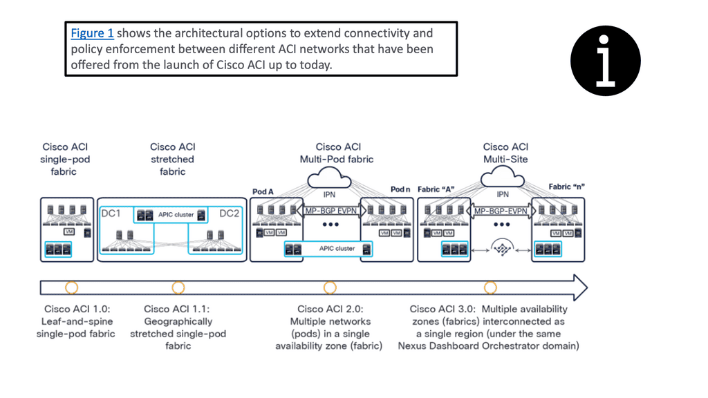
I have always found extending data risky when undergoing data center network design projects. However, the Cisco ACI architecture can be extended without the traditional Layer 2 and 3 Data Center Interconnect (DCI) mechanisms. Here, we can use Multi-Pod and Multi-Site to better control large environments that need to span multiple locations and for applications to share those multiple locations in active-active application deployments.
When considering data center designs, terms such as active-active and active-passive are often discussed. In addition, enterprises are generally looking for data center solutions that provide geographical redundancy for their applications.
Enterprises also need to be able to place workloads in any data center where computing capacity exists—and they often need to distribute members of the same cluster across multiple data center locations to provide continuous availability in the event of a data center failure. The ACI gives us options for extending the fabric to multiple locations and location types.
For example, there are stretched fabric, multi-pod, multi-site designs, and, more recently, Cisco Cloud ACI.
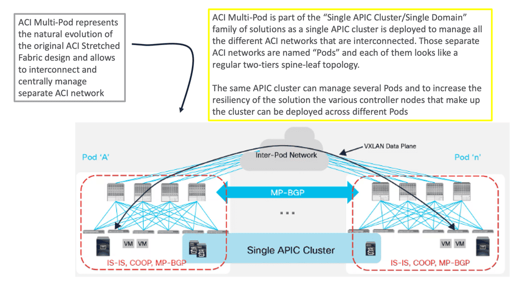
ACI design: Multi pod
The ACI Multi-Pod is the next evolution of the original stretch fabric design we discussed. The architecture consists of multiple ACI Pods connected by an IP Inter-Pod Layer 3 network. With the stretched fabric, we have one Pod across several locations. Cisco ACI MultiPod is part of the “single APIC cluster/single domain” family of solutions; a single APIC cluster is deployed to manage all the interconnected ACI networks.
These ACI networks are called “pods,” Each looks like a regular two-tier spine-leaf topology. The same APIC cluster can manage several pods. All of the nodes deployed across the individual pods are under the control of the same APIC cluster. The separate pods are managed as if they were logically a single entity. This gives you operational simplicity. We also have a fault-tolerant fabric since each Pod has isolated control plane protocols.
ACI design: Cisco cloud ACI
Cisco Cloud APIC is an essential new solution component introduced in the architecture of Cisco Cloud ACI. It plays the equivalent of APIC for a cloud site. Like the APIC for on-premises Cisco ACI sites, Cloud APIC manages network policies for the cloud site it runs on by using the Cisco ACI network policy model to describe the policy intent.
ACI design: Multisite
ACI Multi-Site enables you to interconnect separate APIC cluster domains or fabric, each representing a separate availability zone. As a result, we have separate and independent APIC domains and fabrics. This way, we can manage multiple fabrics as regions or availability zones. ACI Multi-Site is the easiest DCI solution in the industry. Communication between endpoints in separate sites (Layers 2 and 3) is enabled simply by creating and pushing a contract between the endpoints’ EPGs.