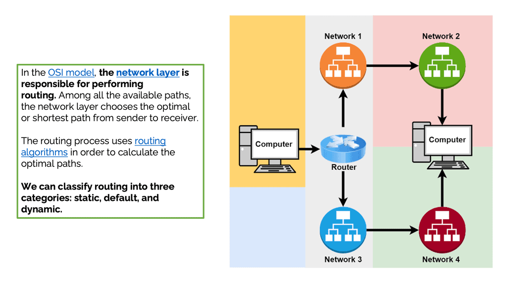
Understanding Data Center Fabric
– Data center fabric refers to the underlying network infrastructure that interconnects various elements within a data center. It encompasses a combination of switches, routers, and other networking devices that enable high-speed, reliable, and scalable communication between servers, storage systems, and other components.
– Data center fabric is built upon a robust and scalable architecture that ensures efficient data flow and minimizes bottlenecks. Traditionally, this architecture relied on a three-tier model consisting of core, aggregation, and access layers. However, with the advent of modern technologies, a flatter two-tier model and even fabric-based architectures have gained prominence, offering increased flexibility, reduced latency, and simplified management.
– Implementing a well-designed data center fabric brings forth a multitude of benefits. Firstly, it enhances network performance by providing high bandwidth and low latency, facilitating rapid data transfer and real-time applications. Secondly, data center fabric enables seamless scalability, allowing organizations to effortlessly expand their infrastructure as their needs grow. Moreover, it improves resiliency by offering redundant paths and reducing the risk of single points of failure.
– Designing an efficient and reliable data center fabric requires careful planning and consideration. Factors such as network topology, traffic patterns, bandwidth requirements, and security must be thoroughly evaluated. Additionally, selecting the appropriate switching technologies, such as Ethernet or Fibre Channel, and implementing effective traffic management mechanisms are essential to ensure optimal performance and resource utilization.
**The role of a data center fabric**
In a data center, network devices are typically deployed in two (or sometimes three) highly interconnected layers or fabrics. Unlike traditional multitier architectures, data center fabrics flatten the network architecture, reducing distances between endpoints. This design results in very low latency and very high efficiency.
All data center fabrics share another design goal. In addition to providing a solid layer of connectivity, they transport the complexity of virtualization, segmentation, stretched Ethernet segments, workload mobility, and other services to an overlay that rides on top of the fabric. Underlays are fabrics used in conjunction with overlays.
**Advent of Network Virtualisation**
Due to the advent of network virtualization, applications have also evolved from traditional client/server architecture to highly distributed microservices architectures composed of cloud-native workloads. A scale-out approach connects all components to different access switches instead of having all components on the same physical server
Data center fabric refers to the interconnected network of switches, routers, and other networking devices that form the backbone of a data center. It serves as the highway for data traffic, allowing efficient communication between various components within the data center infrastructure.
1. Network Switches: Network switches form the core of the data center fabric, providing connectivity between servers, storage devices, and other networking equipment. These switches are designed to handle massive data traffic, offering high bandwidth and low latency to ensure optimal performance.
2. Cabling Infrastructure: A well-designed cabling infrastructure is crucial for data center fabric. High-speed fiber optic cables are commonly used to connect various components within the data center, ensuring rapid data transmission and minimizing signal loss.
3. Network Virtualization: Network virtualization technologies, such as software-defined networking (SDN), play a significant role in the data center fabric. By decoupling the network control plane from the physical infrastructure, SDN enables centralized management, improved agility, and flexibility in allocating resources within the data center fabric.
4. Redundancy and High Availability: Data center fabric incorporates redundancy mechanisms to ensure high availability. By implementing redundant switches and links, it provides failover capabilities, minimizing the risk of downtime and maximizing system reliability.
5. Scalability: One of the defining features of data center fabric is its ability to scale horizontally. With the ever-increasing demand for computational power, data center fabric allows for the seamless addition of new devices and resources, ensuring the data center can keep up with growing requirements.
Data Center Fabric with VPC
Data center fabric serves as the foundational layer for cloud providers like Google Cloud, facilitating high-speed data transfer and scalability. It allows for the integration of various network components, creating a unified infrastructure that supports the demands of cloud services. By leveraging a robust fabric, Google Cloud VPC can offer customers a resilient and flexible environment, ensuring that resources are efficiently allocated and managed across diverse workloads.
**Understanding the Basics of VPC**
A Virtual Private Cloud (VPC) is essentially a private network within a public cloud. It allows users to create and manage their own isolated network segments within Google Cloud. With VPC, you can define your own IP address range, create subnets, and configure firewalls and routes. This level of control ensures that your resources are both secure and efficiently organized. Google Cloud’s VPC offers global reach and a high degree of flexibility, making it a preferred choice for many enterprises.

**Key Features and Benefits**
One of the standout features of Google Cloud’s VPC is its global reach, allowing for seamless communication across different regions. This global VPC capability means you can connect resources across the globe without the need for complex VPN setups. Additionally, VPC’s dynamic scalability ensures that your network can grow alongside your business needs. With features like private Google access, you can communicate securely with Google services without exposing your data to the public internet.
**Setting Up a VPC on Google Cloud**
Setting up a VPC on Google Cloud is straightforward, thanks to the intuitive interface and comprehensive documentation provided by Google. Start by defining your network’s IP address range and creating subnets in your desired regions. Configure firewall rules to control traffic in and out of your network, ensuring only authorized access. Google Cloud also provides tools like Cloud VPN and Cloud Interconnect to integrate your VPC with on-premises infrastructure, offering a hybrid cloud solution.


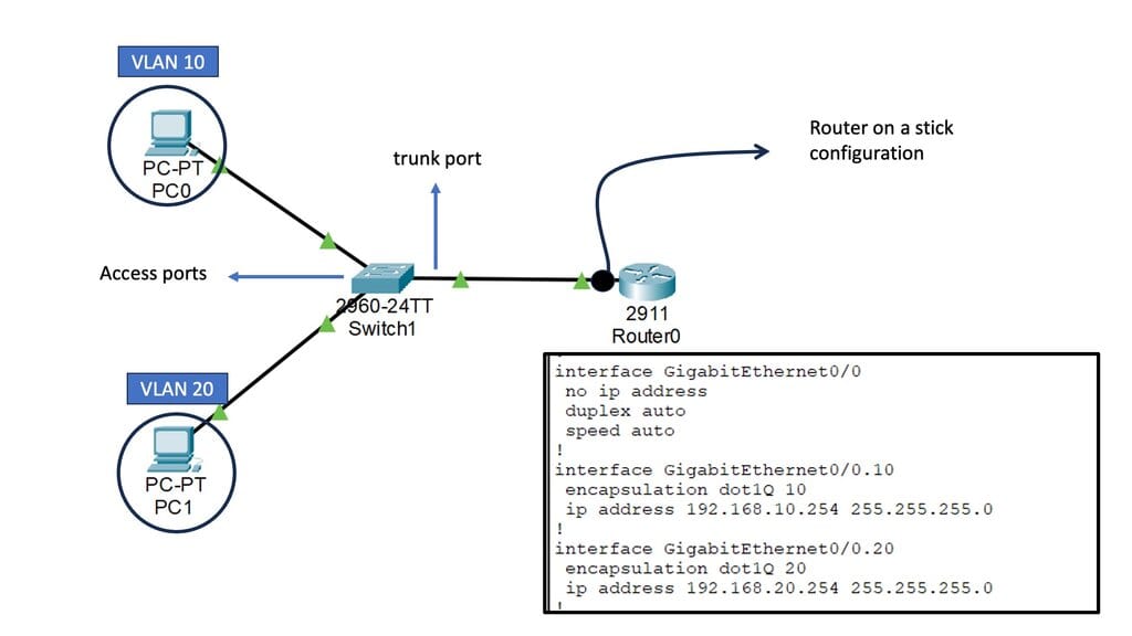
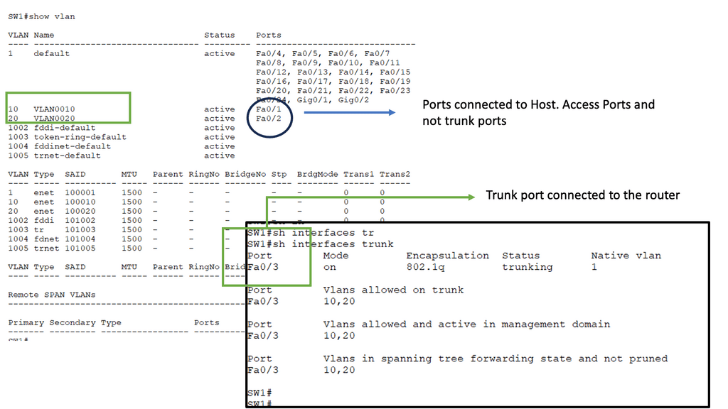
Example: IP Fabric with Clos
Clos fabrics provide physical connectivity between switches, facilitating the network’s goal of connecting workloads and servers in the fabric (and the outside world). Routing protocols are used to connect these endpoints. According to RFC 7938, BGP is the preferred routing protocol, with spines and leaves peering externally at each other (eBGP). A VXLAN-based fabric is built upon such a fabric, which is called an IP fabric.
Data centers typically use Clos fabrics or two-tier spine-and-leaf architectures. In this fabric, data passes through three devices before reaching its destination. Through a leaf device, east-west data center traffic travels upstream from one server to another and downstream to the destination server. The fundamental nature of fabric design is changed due to the absence of a network core.
- With a spine-and-leaf fabric, intelligence is moved to the edges rather than centralized (for example, to implement policies). Endpoint devices (such as top-of-rack switches) or leaf devices (such as top-of-rack switches) can implement it. As a transit layer, the spine devices serve as leaf devices.
- Spine-and-leaf fabrics allow east-west traffic flows to be accommodated more quickly than traditional hierarchical networks.
- In east-west or north-south traffic, spine-and-leaf fabrics become equal. The exact number of devices processes it. This practice can significantly simplify the process of building fabrics with strict delay and jitter requirements.
Google Cloud – Network Connectivity Center
**What is Google Network Connectivity Center?**
Google Network Connectivity Center is a centralized hub for managing network connectivity across various environments. Whether it’s on-premises data centers, virtual private clouds (VPCs), or other cloud services, NCC provides a unified platform to oversee and optimize network operations. By leveraging Google’s robust infrastructure, enterprises can ensure reliable and efficient connectivity, overcoming the complexities of traditional network management.

**Key Features of NCC**
1. **Centralized Management**: One of the standout features of NCC is its ability to provide a single pane of glass for network management. This centralized approach simplifies the oversight of complex network configurations, reducing the risk of misconfigurations and improving operational efficiency.
2. **Automated Routing**: NCC utilizes Google’s advanced algorithms to automate routing decisions, ensuring optimal data flow between different network endpoints. This automation not only enhances performance but also reduces the manual effort required to manage network routes.
3. **Integrated Security**: Security is a top priority for any network. NCC incorporates robust security features, including encryption and authentication, to protect data as it traverses different network segments. This integrated security framework helps safeguard sensitive information and ensures compliance with industry standards.


**Benefits for NCC Data Centers**
1. **Enhanced Connectivity**: With NCC, data centers can achieve seamless connectivity across diverse environments. This enhanced connectivity translates to improved application performance and a better user experience, as data can be accessed and transferred without significant delays or interruptions.
2. **Scalability**: As businesses grow, their network requirements evolve. NCC offers the scalability needed to accommodate this growth, allowing enterprises to expand their network infrastructure without compromising performance or reliability.
3. **Cost Efficiency**: By streamlining network management and reducing the need for manual intervention, NCC can lead to significant cost savings. Enterprises can allocate resources more effectively and focus on strategic initiatives rather than routine network maintenance.
**Impact on Hybrid and Multi-Cloud Environments**
Hybrid and multi-cloud environments are becoming increasingly common as organizations seek to leverage the best of both worlds. NCC plays a crucial role in these environments by providing a cohesive network management solution. It bridges the gap between different cloud services and on-premises infrastructure, enabling a more integrated and efficient network architecture.
Behind the Scenes of Google Cloud Data Centers
– Google Cloud data centers are marvels of engineering, built to handle massive amounts of data traffic and ensure the highest levels of performance and reliability. These facilities are spread across the globe, strategically located to provide efficient access to users worldwide. From the towering racks of servers to the intricate cooling systems, every aspect is meticulously designed to create an optimal computing environment.
– At the heart of Google Cloud data centers lies the concept of data center fabric. This refers to the underlying network infrastructure that interconnects all the components within a data center, enabling seamless communication and data transfer. Data center fabric is a crucial element in ensuring high-speed, low-latency connectivity between servers, storage systems, and other critical components.
A. Reliable Infrastructure: Google Cloud data centers leverage the power of data center fabric to ensure a reliable and robust infrastructure. By implementing a highly redundant fabric architecture, Google Cloud can provide a stable and resilient environment for hosting critical applications and services.
B. Global Interconnectivity: Google Cloud’s data center fabric extends across multiple regions, enabling seamless interconnectivity between data centers worldwide. This global network backbone ensures efficient data transfer and low-latency communication, allowing businesses to operate on a global scale..
Google Cloud Network Tiers
Understanding Network Tiers
Network tiers in Google Cloud refer to the different service levels offered for egress traffic from your virtual machines (VMs) to the internet. Google Cloud provides two primary network tiers: Premium Tier and Standard Tier. Each tier offers distinct features and cost structures, allowing you to tailor your network setup to your specific requirements.
The Premium Tier is designed for businesses that prioritize top-notch performance and global connectivity. It leverages Google’s vast private network infrastructure, ensuring low-latency and high-bandwidth connections between your VMs and the internet. With its global reach, the Premium Tier enables efficient data transfer across regions, making it an ideal choice for latency-sensitive applications and global workloads.
If cost optimization is a critical factor for your business, the Standard Tier provides a compelling solution. While it may not offer the same performance capabilities as the Premium Tier, the Standard Tier delivers cost-effective egress traffic pricing, making it suitable for applications with less stringent latency requirements. The Standard Tier still ensures reliable connectivity and offers a robust network backbone to support your workloads.


What is VPC Peering?
VPC peering is a connection between two Virtual Private Cloud networks that enables communication between them using private IP addresses. It allows resources within separate VPC networks to interact as if they were on the same network. Unlike traditional VPN connections or public internet connectivity, VPC peering ensures secure and direct communication between VPC networks.

a) Enhanced Connectivity: VPC peering simplifies establishing private connections between VPC networks, enabling seamless data transfer and communication.
b) Cost Efficiency: By leveraging VPC peering, businesses can reduce their reliance on costly external network connections or VPNs, leading to potential cost savings.
c) Low Latency: With VPC peering, data travels through Google’s private network infrastructure, resulting in minimal latency and faster response times.
d) Scalability and Flexibility: VPC peering allows you to connect multiple VPC networks within the same project or across different projects, ensuring scalability as your infrastructure grows.

**Data Center Fabric Performance**
1. Low Latency: Data center fabric minimizes the delay in data transmission, enabling real-time communication and faster application response times. This is crucial for latency-sensitive applications like financial trading or online gaming.
2. High Bandwidth: By utilizing technologies like high-speed Ethernet and InfiniBand, data center fabric can achieve impressive bandwidth capacities. This allows data centers to handle heavy workloads and support bandwidth-hungry applications such as big data analytics or video streaming.
3. Scalability: Data center fabric is designed to scale seamlessly, accommodating the ever-increasing demands of modern data centers. Its modular structure and distributed architecture enable easy expansion without compromising performance or introducing bottlenecks.
Optimizing Performance with Data Center Fabric
1. Traffic Optimization: The intelligent routing capabilities of data center fabric help optimize traffic flow, ensuring efficient data delivery and minimizing congestion. By intelligently distributing traffic across multiple paths, it balances the load and prevents bottlenecks.
2. Redundancy and Resilience: Data center fabric incorporates redundancy mechanisms to ensure high availability and fault tolerance. In the event of a link or node failure, it dynamically reroutes traffic to alternative paths, minimizing downtime and maintaining uninterrupted services.
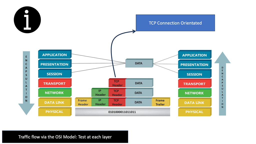
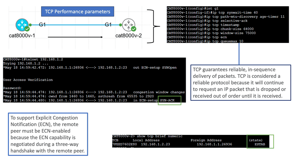
Understanding TCP Performance Parameters
TCP performance parameters are crucial settings that determine how TCP behaves during data transmission. These parameters govern various aspects, such as congestion control, retransmission timeouts, and window sizes. Network administrators can optimize TCP performance based on specific requirements by fine-tuning these parameters.
Let’s explore some of the essential TCP performance parameters that can significantly impact network performance:
1. Congestion Window (CWND): The congestion window represents the number of unacknowledged packets a sender can transmit before expecting an acknowledgment. Properly adjusting CWND based on network conditions can prevent congestion and improve overall throughput.
2. Maximum Segment Size (MSS): MSS refers to the largest amount of data a TCP segment can carry. Optimizing the MSS value based on the network’s Maximum Transmission Unit (MTU) can enhance performance by reducing unnecessary fragmentation and reassembly.
3. Retransmission Timeout (RTO): RTO determines the time a sender waits before retransmitting unacknowledged packets. Adjusting RTO based on network latency and congestion levels can prevent unnecessary retransmissions and improve efficiency.
It is crucial to consider the specific network environment and requirements to optimize TCP performance. Here are some best practices for optimizing TCP performance parameters:
1. Analyze Network Characteristics: Understanding network characteristics such as latency, bandwidth, and congestion levels is paramount. Conducting thorough network analysis helps determine the ideal values for TCP performance parameters.
2. Test and Evaluate: Performing controlled tests and evaluations with different parameter configurations can provide valuable insights into the impact of specific settings. It allows network administrators to fine-tune parameters for optimal performance.
3. Keep Up with Updates: TCP performance parameters are not static; new developments and enhancements continually emerge. Staying updated with the latest research, standards, and recommendations ensures the utilization of the most effective TCP performance parameters.
Understanding TCP MSS
TCP MSS refers to the maximum amount of data encapsulated within a single TCP segment. It plays a vital role in ensuring efficient data transmission across networks. By limiting the segment size, TCP MSS helps prevent fragmentation, reduces latency, and provides reliable delivery of data packets. To comprehend TCP MSS fully, let’s explore its essential components and how they interact.
Various factors impact TCP MSS, including network infrastructure, operating systems, and application configurations. Network devices such as routers and firewalls often impose limitations on MSS due to MTU (Maximum Transmission Unit) constraints. Additionally, the MSS value can be adjusted at the operating system level or within specific applications. Understanding these factors is crucial for optimizing TCP MSS in different scenarios.
Aligning TCP MSS with the underlying network infrastructure is essential to achieving optimal network performance. This section will discuss several strategies for optimizing TCP MSS. Firstly, Path MTU Discovery (PMTUD) can dynamically adjust the MSS value based on the network path’s MTU. Additionally, tweaking TCP stack parameters, such as the TCP window size, can enhance performance and throughput. We will also explore the benefits of setting appropriate MSS values for VPN tunnels and IPv6 deployments.

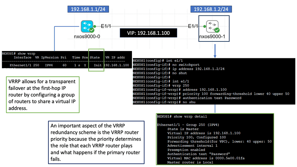
Understanding VRRP
VRRP, also known as Virtual Router Redundancy Protocol, is a network protocol that enables multiple routers to work together as a single virtual router. It provides redundancy and ensures high availability by electing a master router and one or more backup routers. The Nexus 9000 Series takes VRRP to the next level with its cutting-edge features and performance enhancements.
The Nexus 9000 Series VRRP offers numerous benefits for network administrators and businesses. First, it ensures uninterrupted network connectivity by seamlessly transitioning from the master router to a backup router in case of failures. This high availability feature minimizes downtime and enhances productivity. Nexus 9000 Series VRRP also provides load-balancing capabilities, distributing traffic efficiently across multiple routers for optimized performance.
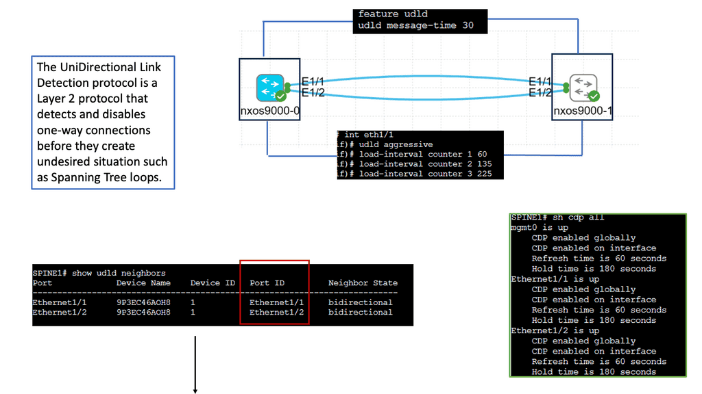
Understanding Unidirectional Links
Unidirectional links occur when traffic can flow in only one direction, causing communication breakdowns and network instability. Various factors, such as faulty cables, hardware malfunctions, or misconfiguration, can cause these links. Identifying and resolving unidirectional links is vital to maintaining a robust network infrastructure.
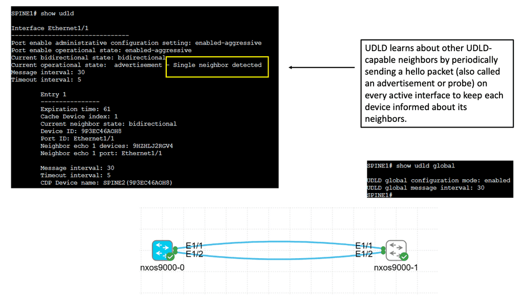
Cisco Nexus 9000 switches offer an advanced feature called Unidirectional Link Detection (UDLD) to address the issue of unidirectional links. UDLD actively monitors the status of connections and detects any unidirectional link failures. By periodically exchanging heartbeat messages between switches, UDLD ensures bidirectional connectivity and helps prevent potential network outages.
Implementing UDLD on Cisco Nexus 9000 switches brings several advantages to network administrators and organizations. Firstly, it enhances network reliability by proactively detecting and alerting about potential unidirectional link failures. Secondly, it minimizes the impact of such failures by triggering fast convergence and facilitating rapid link recovery. Additionally, UDLD helps troubleshoot network issues by providing detailed information about the affected links and their status.
Routing and Switching in Data Center Fabric
The Role of Routing in Data Center Fabric
Routing is vital to the data center fabric, directing network traffic along the most optimal paths. It involves examining IP addresses, determining the best routes, and forwarding packets accordingly. With advanced routing protocols, data centers can achieve high availability, load balancing, and fault tolerance, ensuring uninterrupted connectivity and minimal downtime.
The Significance of Switching in Data Center Fabric
Switching plays a crucial role in data center fabric by facilitating the connection of multiple devices within the network. It involves efficiently transferring data packets between different servers, storage systems, and endpoints. Switches provide the necessary intelligence to route packets to their destinations, ensuring fast and reliable data transmission.
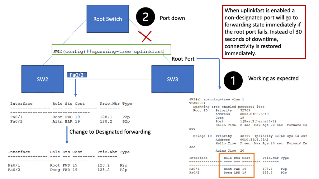
Understanding Spanning Tree Protocol
The first step in comprehending spanning tree uplink fast is to grasp the fundamentals of the spanning tree protocol (STP). STP ensures a loop-free network topology by identifying and blocking redundant paths. Maintaining a tree-like structure enables the efficient transfer of data packets within a network.
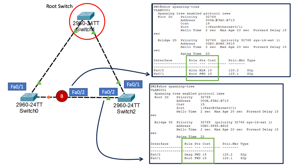
The Need for Uplink Fast
While STP is a vital guardian against network loops, it can also introduce delays when switching between redundant paths. This is where spanning tree uplink fast comes into play. By bypassing STP’s listening and learning states on direct uplinks, uplink fast significantly reduces the convergence time during network failures or topology changes.
Uplink fast operates by utilizing the port roles defined in STP. When an uplink port becomes available, uplink fast leverages the port fast feature to transition it directly to the forwarding state. This eliminates the delay caused by the listening and learning states, allowing for faster convergence and improved network performance.
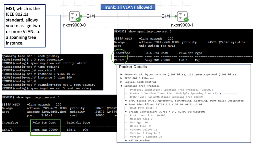
Unveiling Multiple Spanning Tree (MST)
MST builds upon the foundation of STP by allowing multiple instances of spanning trees to coexist within a network. This enables network administrators to divide the network into various regions, each with its independent spanning tree. By doing so, MST better utilizes redundant links and enhances network performance. It also allows for much finer control over network traffic and load balancing.
Enhanced Network Resiliency: The primary advantage of STP and MST is the improved resiliency they offer. By eliminating loops and providing alternate paths, these protocols ensure that network failures or link disruptions do not lead to complete network downtime. They enable rapid convergence and automatic rerouting, minimizing the impact of failures on network operations.
Load Balancing and Bandwidth Optimization: Another significant advantage of STP and MST is distributing traffic across multiple paths. By intelligently utilizing redundant links, these protocols enable load balancing, preventing congestion and maximizing available bandwidth. This results in improved network performance and efficient utilization of network resources.
Simplified Network Management: STP and MST simplify network management by automating choosing the best paths and ensuring network stability. These protocols automatically adjust to changes in network topology, making it easier for administrators to maintain and troubleshoot the network. Additionally, with MST’s ability to divide the network into regions, administrators gain more granular control over network traffic and can apply specific configurations to different areas.
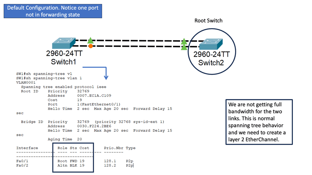
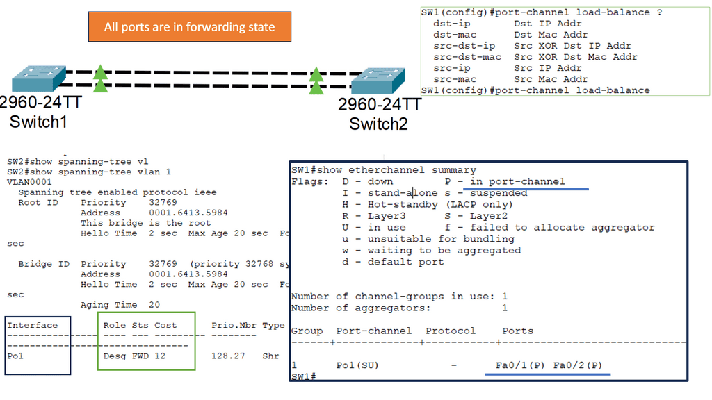
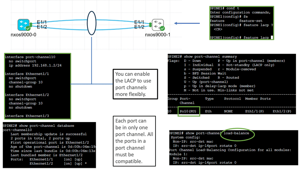
Understanding Layer 2 EtherChannel
Layer 2 EtherChannel, or link aggregation or port channel, bundles multiple physical links to act as a single logical link. This increases bandwidth, improves load balancing, and provides redundancy in case of link failures. This technique allows network administrators to maximize network capacity and achieve greater efficiency.
Setting up Layer 2 Etherchannel requires careful configuration. First, the switches involved need to be compatible and support Etherchannel. Second, the ports on each switch participating in the Etherchannel must be properly configured. This consists of configuring the same channel group number, mode (such as “on” or “active”), and load balancing algorithm. Once the configuration is complete, the Etherchannel will be formed, and the bundled links will act as a single logical link.
Understanding Layer 3 Etherchannel
Layer 3 etherchannel, also known as routed etherchannel, combines the strengths of link aggregation and routing. It allows for bundling multiple physical links into a single logical link, enabling load balancing and fault tolerance at Layer 3. This technology operates at the network layer of the OSI model, making it a valuable tool for optimizing network performance.
Increased Bandwidth: Layer 3 etherchannel provides a higher overall bandwidth capacity by aggregating multiple links. This helps alleviate network congestion and facilitates smooth data transmission across the network.
-Load Balancing: Layer 3 etherchannel intelligently distributes traffic across the bundled links, distributing the load evenly and preventing bottlenecks. This ensures efficient utilization of available resources and minimizes latency.
-Redundancy and High Availability: With Layer 3 etherchannel, if one link fails, the traffic seamlessly switches to the remaining active links, ensuring uninterrupted connectivity. This redundancy feature enhances network reliability and minimizes downtime.

Understanding Cisco Nexus 9000 Port Channel
Cisco Nexus 9000 Port Channel is a technology that allows multiple physical links to be bundled into a single logical link. This aggregation enables higher bandwidth utilization and load balancing across the network. By combining the capacity of multiple ports, organizations can overcome bandwidth limitations and achieve greater throughput.
One critical advantage of the Cisco Nexus 9000 Port Channel is its ability to enhance network reliability. By creating redundant links, the port channel provides built-in failover capabilities. In a link failure, traffic seamlessly switches to the available links, ensuring uninterrupted connectivity. This redundancy safeguards against network downtime and maximizes uptime for critical applications.
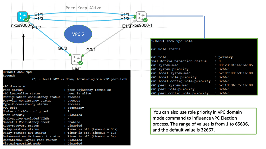
Understanding Virtual Port Channel (VPC)
VPC is a technology that allows the formation of a virtual link between two Cisco Nexus switches. It enables the switches to appear as a single logical entity, providing redundancy and load balancing. By combining multiple physical links, VPC enhances network resiliency and performance.
Configuring VPC involves a series of steps that ensure seamless operation. First, the Nexus switches must establish a peer link to facilitate control plane communication. Next, the VPC domain is created, and a unique domain ID is assigned. Then, the member ports are added to the VPC domain, forming a port channel. Finally, the VPC peer-keepalive link is configured to monitor the health of the VPC peers.

**Data Center Fabric Security**
- Network Segmentation and Isolation
One of the key security characteristics of data center fabric lies in its ability to implement network segmentation and isolation. By dividing the network into smaller, isolated segments, potential threats can be contained, preventing unauthorized access to sensitive data. This segmentation also improves network performance and allows for easier management of security policies.
- Secure Virtualization
Data center fabric leverages virtualization technologies to efficiently allocate computing resources. However, security remains a top priority within this virtualized environment. Robust virtualization security measures such as hypervisor hardening, secure virtual machine migration, and access control mechanisms are implemented to ensure the integrity and confidentiality of the virtualized infrastructure.
- Intrusion Prevention and Detection
Protecting the data center fabric from external and internal threats requires advanced intrusion prevention and detection systems. These systems continuously monitor network traffic, analyzing patterns and behaviors to detect any suspicious activity. With real-time alerts and automated responses, potential threats can be neutralized before they cause significant damage.
Understanding MAC ACLs
MAC ACLs, or Media Access Control Access Control Lists, provide granular control over network traffic by filtering packets based on their source and destination MAC addresses. Unlike traditional IP-based ACLs, MAC ACLs operate at the data link layer, enabling network administrators to enforce security policies more fundamentally. By understanding the basics of MAC ACLs, you can harness their power to fortify your network defenses.
Monitoring and troubleshooting MAC ACLs are vital aspects of maintaining a secure network. This section will discuss various tools and techniques available on the Nexus 9000 platform to monitor MAC ACL hits, analyze traffic patterns, and troubleshoot any issues that may arise. By gaining insights into these methods, you can ensure the ongoing effectiveness of your MAC ACL configurations.

The Role of ACLs in Network Security
Access Control Lists (ACLs) act as traffic filters, allowing or denying network traffic based on specific criteria. While traditional ACLs operate at the router or switch level, VLAN ACLs provide an additional layer of security by filtering traffic within VLANs themselves. This granular control ensures only authorized communication between devices within the same VLAN.
To configure VLAN ACLs, administrators must define rules determining which traffic is permitted and which is blocked within a specific VLAN. These rules can be based on source and destination IP addresses, protocols, ports, or any combination of these factors. By carefully crafting ACL rules, network administrators can enforce security policies, prevent unauthorized access, and mitigate potential threats.
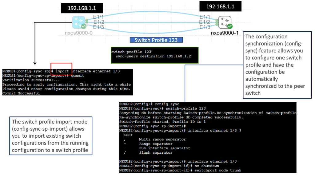
 Understanding Nexus Switch Profiles
Nexus Switch Profiles are a powerful tool Cisco provides for network administrators to streamline and automate network configurations. These profiles enable consistent deployment of settings across multiple switches, eliminating the need for manual configurations on each device individually. By creating a centralized profile, administrators can ensure uniformity in network settings, reducing the chances of misconfigurations and enhancing network reliability.
a. Simplified Configuration Management: With Nexus Switch Profiles, administrators can define a set of configurations for various network devices. These configurations can then be easily applied to multiple switches simultaneously, reducing the time and effort required for manual configuration tasks.
b. Scalability and Flexibility: Nexus Switch Profiles allow for easy replication of configurations across numerous switches, making them ideal for large-scale network deployments. Additionally, these profiles can be modified and updated according to the network’s evolving needs, ensuring flexibility and adaptability.
c. Enhanced Consistency and Compliance: Administrators can ensure consistent network behavior and compliance with organizational policies by enforcing a standardized set of configurations through Nexus Switch Profiles, which helps maintain network stability and security.
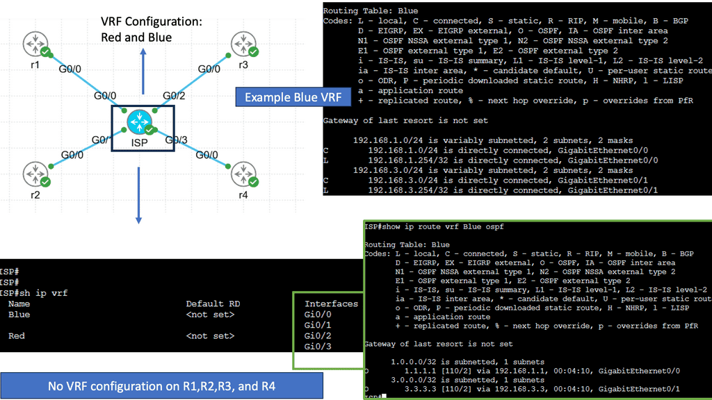
Understanding Virtual Routing and Forwarding
Virtual routing and forwarding, also known as VRF, is a mechanism that enables multiple virtual routing tables to coexist within a single physical router or switch. Each VRF instance operates independently, segregating network traffic and providing isolated routing domains. Organizations can achieve network segmentation by creating these virtual instances, allowing different departments or customers to maintain their distinct routing environments.
Real-World Applications of VRF
VRF finds applications in various scenarios across different industries. In large enterprises, VRF facilitates the segregation of network traffic between different departments, optimizing performance and security. Internet service providers (ISPs) utilize VRF to offer virtual private network services to their customers, ensuring secure and isolated connectivity. Moreover, VRF is instrumental in multi-tenant environments, enabling cloud service providers to offer isolated network domains to their clients.

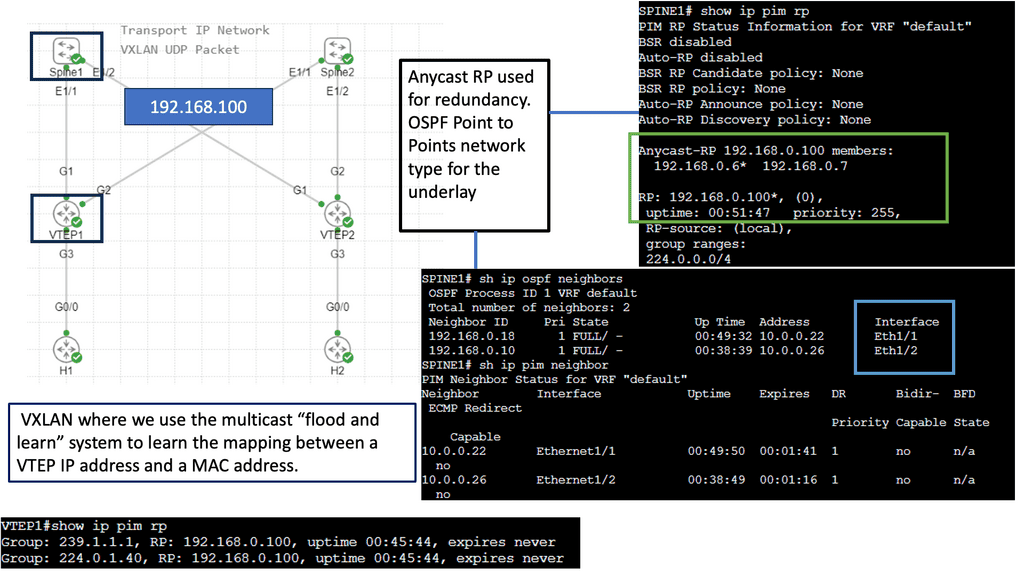
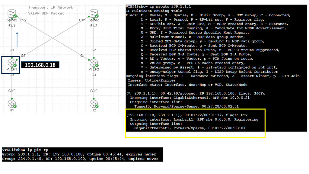
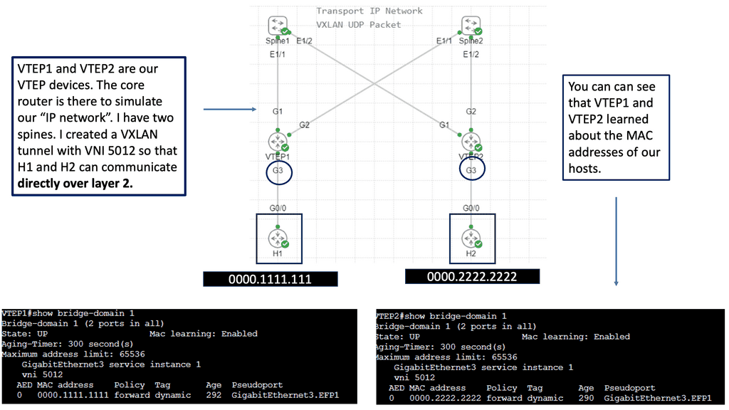
VXLAN Fabric
While utilizing the same physically connected 3-stage Clos network, VXLAN fabrics introduce an abstraction level into the network that elevates workloads and the services they provide into another layer called the overlay. An encapsulation method such as Generic Routing Encapsulation (GRE) or MPLS (which adds an MPLS label) is used to accomplish this. In these tunneling mechanisms, packets are tunneled from one point to another utilizing the underlying network. A VXLAN header is added to IP packets containing a UDP header, a VXLAN header, and an IP header. VXLAN Tunnel Endpoints (VTEPs) are devices configured to encapsulate VXLAN traffic.
Flood and Learn Mechanism
At the heart of VXLAN lies the Flood and Learn mechanism, which plays a crucial role in efficiently forwarding network traffic. When a VM sends a frame to a destination VM residing in a different VXLAN segment, the frame is flooded across the VXLAN overlay network. The frame is efficiently distributed using multicast to all relevant VTEPs (VXLAN Tunnel Endpoint) within the same VXLAN segment. Each VTEP learns the MAC (Media Access Control) addresses of the VMs within its segment, allowing for optimized forwarding of subsequent frames.
Multicast plays a pivotal role in VXLAN Flood and Learn, offering several advantages over unicast or broadcast-based approaches. First, multicast enables efficient traffic distribution by replicating frames only to the relevant VTEPs within a VXLAN segment. This reduces unnecessary network overhead and enhances overall performance. Additionally, multicast allows for dynamic membership management, ensuring that VTEPs join and leave multicast groups as needed without manual configuration.
VXLAN Flood and Learn with Multicast has found widespread adoption in various use cases. Data center networks, particularly those with high VM density, benefit from the scalability and flexibility provided by VXLAN. Large-scale VM migrations and workload mobility can be seamlessly achieved by leveraging multicast without compromising network performance. Furthermore, VXLAN Flood and Learn enables efficient utilization of network resources, optimizing bandwidth usage and reducing latency.

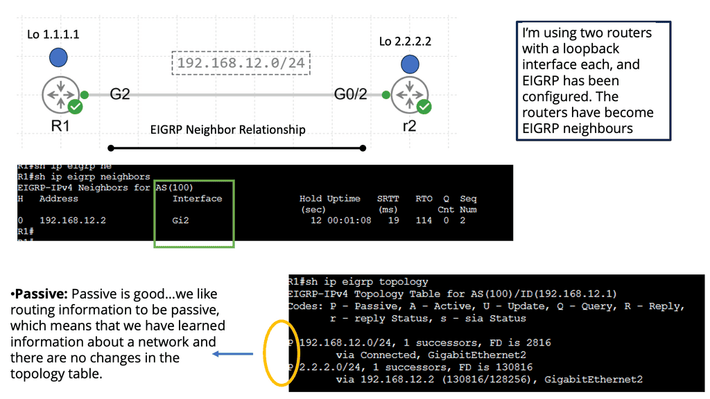
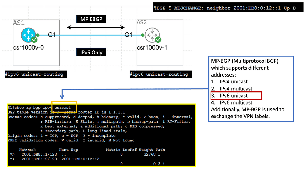
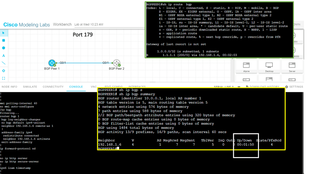
Understanding BGP Route Reflection
BGP route reflection is a mechanism that alleviates the full mesh requirement in BGP networks. Establishing a full mesh of BGP peers in large-scale networks can become impractical, leading to increased complexity and resource consumption. Route reflection enables route information to be selectively propagated across BGP speakers, resulting in a more scalable and manageable network infrastructure.
To implement BGP route reflection, a network administrator must identify routers that will act as route reflectors. These routers are responsible for reflecting BGP updates from one client to another, ensuring the propagation of routing information without requiring a full mesh. Careful design considerations, such as route reflector hierarchy and cluster configuration, are essential for optimal scalability and performance.


Example: Data Center Fabric – FabricPath
Network devices are deployed in highly interconnected layers, represented as a fabric. Unlike traditional multitier architectures, a data center fabric effectively flattens the network architecture, reducing the distance between endpoints within the data center. An example of a data center fabric is FabricPath.
Cisco has validated FabricPath as an Intra-DC Layer 2 multipath technology. Design cases are also available where FabricPath is deployed for DCI ( Data Center Interconnect ). Regarding a FabricPath DCI option, design carefully over short distances with reliable interconnects, such as Dark Fiber or Protected Dense Wavelength Division Multiplexing (DWDM ).
FabricPath designs are suitable for a range of topologies. Unlike hierarchical virtual Port Channel ( vPC ) designs, FabricPath does not need to follow any topology. It can accommodate any design type: full mesh, partial mesh, hub, and spoke topologies.
Example: Data Center Fabric – Cisco ACI
ACI Cisco is a software-defined networking (SDN) architecture that brings automation and policy-driven application profiles to data centers. By decoupling network hardware and software, ACI provides a flexible and scalable infrastructure to meet dynamic business requirements. It enables businesses to move from traditional, manual network configurations to a more intuitive and automated approach.
One of the defining features of Cisco ACI is its application-centric approach. It allows IT teams to define policies based on application requirements rather than individual network components. This approach simplifies network management, reduces complexity, and ensures that network resources are aligned with the needs of the applications they support.
Related: Before you proceed, you may find the following posts helpful:
Flattening the network architecture
In this current data center network design, network devices are deployed in two interconnected layers, representing a fabric. Sometimes, massive data centers are interconnected with three layers. Unlike conventional multitier architectures, a data center fabric flattens the network architecture, reducing the distance between endpoints within the data center. This design results in high efficiency and low latency. Very well suited for east-to-west traffic flows.
Data center fabrics provide a solid layer of connectivity in the physical network and move the complexity of delivering use cases for network virtualization, segmentation, stretched Ethernet segments, workload mobility, and various other services to an overlay that rides on top of the fabric.
When paired with an overlay, the fabric itself is called the underlay. The overlay could be deployed with, for example, VXLAN. To gain network visibility into user traffic, you would examine the overlay, and the underlay is used to route traffic between the overlay endpoints.
VXLAN, short for Virtual Extensible LAN, is a network virtualization technology that enables the creation of virtual networks over an existing physical network infrastructure. It provides a scalable and flexible approach to address the challenges posed by traditional VLANs, such as limited scalability, spanning domain constraints, and the need for manual configuration.
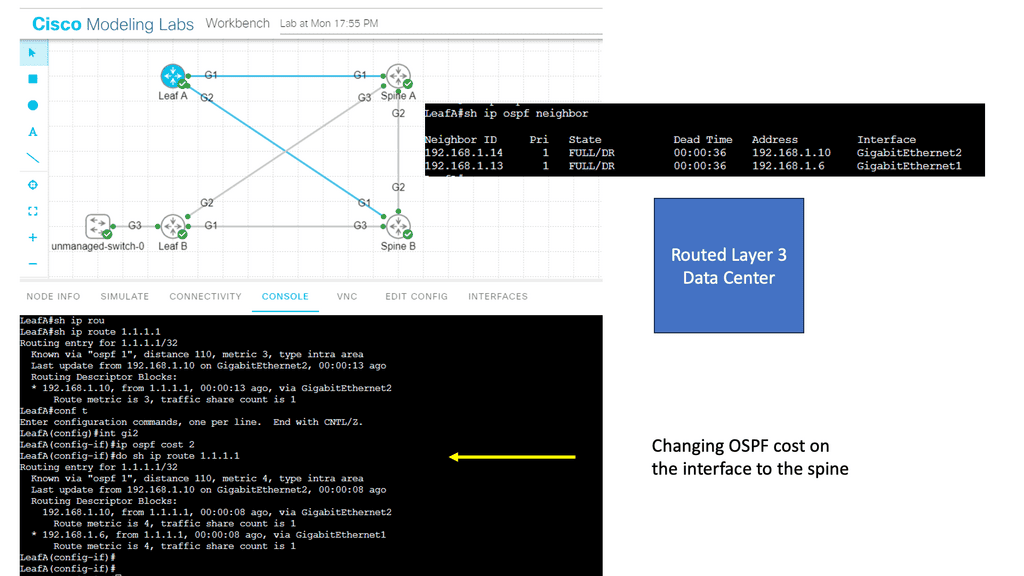
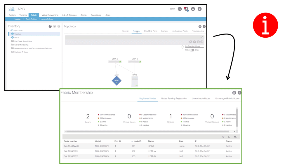
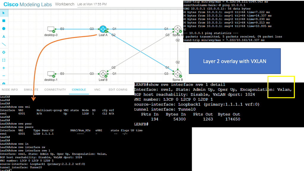
Guide on overlay networking with VXLAN
The following example shows VLXAN tunnel endpoints on Leaf A and Leaf B. The bridge domain is mapped to a VNI on G3 on both leaf switches. This enables a Layer 2 overlay for the two hosts to communicate. This VXLAN overlay goes across Spine A and Spine B.
Note that the Spine layer, which acts as the core network, a WAN network, or any other type of Routed Layer 3 network, has no VXLAN configuration. We have flattened the network while providing Layer 2 connectivity over a routed core.
Fabricpath Design: Problem Statement
Key Features of Cisco Fabric Path:
Transparent Interconnection: Cisco Fabric Path allows for creating a multi-path forwarding infrastructure that provides transparent Layer 2 connectivity between devices within a network. This enables the efficient utilization of available bandwidth and simplifies network design.
Scalability: With Cisco Fabric Path, organizations can quickly scale their network infrastructure to accommodate growing data loads. It supports up to 16 million virtual network segments, enabling seamless expansion of network resources without compromising performance.
Fault Tolerance: Cisco Fabric Path incorporates advanced fault-tolerant mechanisms like loop-free topology and equal-cost multipath routing. These features ensure high availability and resiliency, minimizing the impact of network failures and disruptions.
Traffic Optimization: Cisco Fabric Path employs intelligent load-balancing techniques to distribute traffic across multiple paths, optimizing network utilization and reducing congestion. This results in improved application performance and enhanced user experience.
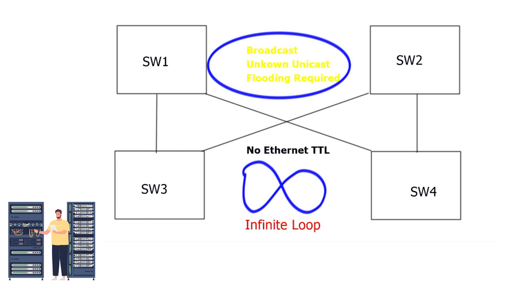
The problem with traditional classical Ethernet is the flooding behavior of unknown unicasts and broadcasts and the process of MAC learning. All switches must learn all MAC addresses, leading to inefficient resource use. In addition, Ethernet has no Time-to-Live ( TTL ) value, and if precautions are not in place, it could cause an infinite loop.
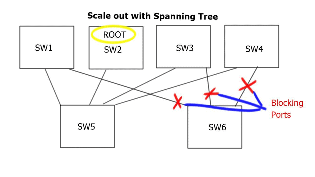
Deploying Spanning Tree Protocol ( STP ) at Layer 2 blocks loops, but STP has many known limitations. One of its most significant flaws is that it offers a single topology for all traffic with one active forwarding path. Scaling the data center with classical Ethernet and spanning trees is inefficient as it blocks all but one path. With spanning trees’ default behavior, the benefits of adding extra spines do not influence bandwidth or scalability.
Possible alternatives
Multichassis EtherChannel
To overcome these limitations, Cisco introduced Multichassis EtherChannel ( MEC ). MEC comes in two flavors: Virtual Switching System ( VSS ) with Catalyst 6500 series or Virtual Port Channel ( vPC ) with Nexus Series. Both offer active/active forwarding but present scalability challenges when scaling out Spine / Core layers. Additionally, complexity increases when deploying additional spines.
Multiprotocol Label Switching
Another option would be to scale out with Multiprotocol Label Switching ( MPLS ). Replace Layer 2 switching with Layer 3 forwarding and MPLS with Layer 2 pseudowires. This type of complexity would lead to an operational nightmare. The prevalent option is to deploy Layer 2 multipath with THRILL or FabricPath. In intra-DC communication, Layer 2 and Layer 3 designs are possible in two forms: Traditional DC design and Switched DC design.
FabricPath VLANs use Conversational Learning, meaning a subset of MAC addresses is learned at the network’s edge. Conversation learning consists of a three-way handshake. Each interface learns the MAC addresses of interested hosts. Compared to classical Ethernet, each switch device learns all MAC addresses for that VLAN.
- Traditional DC design replaces hierarchical vPC and STP with FabricPath. The core, distribution, and access elements stay the same. The same layered hierarchical model exists, but with FabricPath in the core.
- Switched DC design based on Clos Fabrics. Integrate additional Spines for Layer 2 and Layer 3 forwarding.
Traditional data center design
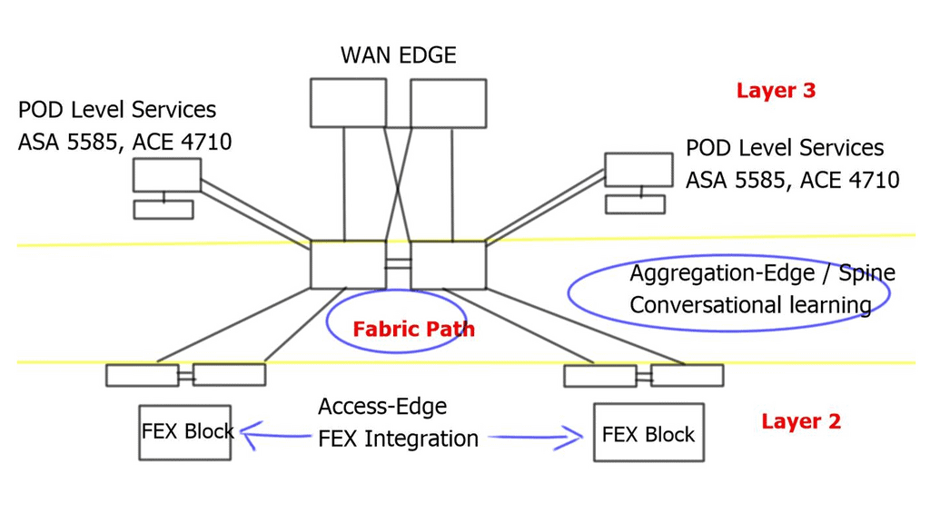
Fabric Path in the core replaces vPC. It still uses port channels, but the hierarchical vPC technology previously used to provide active/active forwarding is not required. Instead, designs are based on modular units called PODs; within each POD, traditional DC technologies exist, such as vPC. Active/active ( dual-active paths ) forwarding based on a two-node Spine, Hot Standby Router Protocol ( HSRP ), announces the virtual MAC of the emulated switch from each of the two cores. For this to work, implement vPC+ on the inter-spine peer links.
Switched data center design
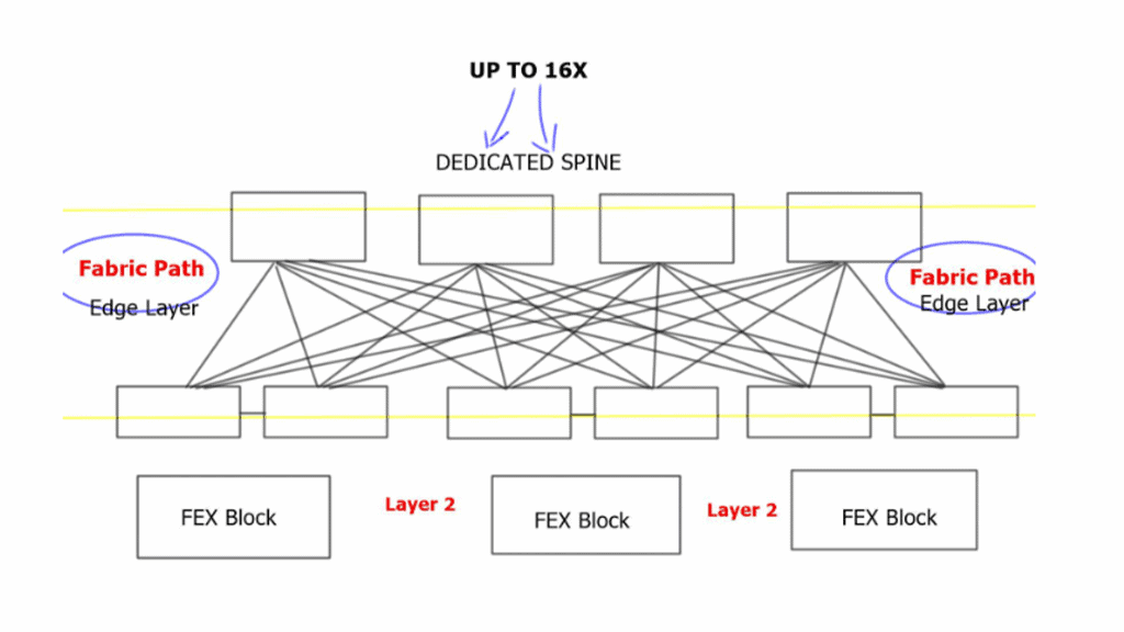
Each edge node has equidistant endpoints to each other, offering predictable network characteristics. From FabricPath’s outlook, the entire Spine Layer is one large Fabric-based POD. In the traditional model presented above, port and MAC address capacity are key factors influencing the ability to scale out. The key advantage of Clos-type architecture is that it expands the overall port and bandwidth capacity within each POD.
Implementing load balancing 4 wide spines challenges traditional First Hop Redundancy Protocol ( FHRP ) like HSRP, which works with 2 active pairs by default. Implementing load balancing 4 wide spines with VLANs allowed on certain links is possible but can cause link polarization.
For optimized designs, utilize a redundancy protocol to work with a 4-node gateway. Deploy Gateway Load Balancing Protocol ( GLBP ) and Anycast FHRP. GLBP uses a weighting parameter that allows Address Resolution Protocol ( ARP ) requests to be answered by MAC addresses pointing to different routers. Anycast FHRP is the recommended solution for designs with 4 or more spine nodes.
FabricPath Key Points:
|