data center design

Open Networking

ENGINEERING GUIDE · OPEN NETWORKING

Open Networking — From Disaggregated Hardware to Programmable Fabrics

Open networking is not a single product or protocol. It is an architectural approach that separates hardware, network software, control, telemetry and automation so infrastructure can become more programmable, interoperable and adaptable.

The important engineering shift is not simply replacing a proprietary platform. It is separating the components of the network so that hardware, software, control and operations can evolve independently.
01 · DISAGGREGATE

Separate Hardware

Treat switching hardware and network software as independently selectable components.

02 · PROGRAM

Expose Control

Use protocols, APIs and software interfaces to make network behaviour programmable.

03 · AUTOMATE

Operate at Fabric Scale

Move from box-by-box configuration toward repeatable desired-state workflows.

04 · OBSERVE

Measure Network State

Use telemetry and analytics to understand actual network behaviour continuously.

ENGINEERING MODEL
HARDWARE → NETWORK OS → CONTROL → AUTOMATION → TELEMETRY → ANALYTICS
ENGINEERING QUESTION

Can the network change without requiring every layer to be redesigned or every device to be configured independently?

Open networking moves intelligence toward software, automation and common interfaces.
White-Box Networking Open NOS SONiC FRRouting BGP EVPN VXLAN Leaf-Spine OpenConfig gNMI Automation Telemetry
Interactive Open Networking Architecture

Open Networking Architecture Explorer

Explore how open networking separates hardware, network software, control, telemetry and automation to create a more flexible, programmable and vendor-neutral infrastructure.
From hardware dependency to programmable fabric
Hardware
→
Network Software
→
Control
→
Operations
Disaggregation creates independence
DATA PLANE Forward packets
CONTROL PLANE Build routing state
MANAGEMENT Automate & observe
HW
White-Box Hardware
Disaggregated infrastructure

Open networking separates the physical switching platform from the software controlling it, allowing organizations greater freedom in hardware selection.

Layer Data plane
Principle Hardware / software separation
Benefit Vendor flexibility
Result Reduced lock-in
OPEN NETWORKING PRINCIPLE
Hardware becomes a replaceable platform rather than the sole source of network intelligence.

Why disaggregation matters

Traditional networking commonly couples hardware, operating system and features into a single vendor stack. Open networking separates these functions so each layer can evolve independently.

OPEN STANDARDS Common protocols and models allow different components to interoperate.
OPEN SOFTWARE Network operating systems and routing software can evolve independently of hardware.
OPEN APIs Automation systems can program and integrate the network.
OPEN TELEMETRY Network state becomes observable through streaming data and common models.
Open Networking · Interactive Use Case
How the Open Fabric Works
See how a modern leaf-spine fabric separates the routed underlay from the VXLAN overlay while BGP and EVPN provide the control plane.
L3 UNDERLAY
VXLAN OVERLAY
WORKLOADS
BGP EVPN CONTROL PLANE
VNI 10100 · VXLAN SEGMENT
SPINE 1
S1
Transit
SPINE 2
S2
Transit
LEAF 1
L1
VTEP
LEAF 2
L2
VTEP
VM-A
Host A
10.10.1.10
VM-B
Host B
10.10.1.20
VM-C
Host C
10.10.1.30
Open Fabric
Click a device to explore its role in the open fabric.
Underlay
IP + BGP
Control Plane
BGP EVPN
Overlay
VXLAN VNI 10100
Architecture
Leaf / Spine
BGP Underlay Routed IP connectivity between leaf and spine switches.
EVPN Control Plane BGP distributes MAC/IP and endpoint reachability information.
VXLAN Overlay VXLAN carries logical network segments across the IP fabric.
VTEP Leaf switches encapsulate and decapsulate VXLAN traffic.
01 · DEFINE · ARCHITECTURE

What Does “Open” Actually Mean?

Open networking begins by separating the components that traditionally arrive as one integrated platform: hardware, network operating system, control protocols and operational tooling. The engineering objective is reduced coupling, greater choice and programmable interfaces.

Engineering Question Can each layer evolve without forcing the entire network architecture to change with it?
01 · DEFINE · OPEN NETWORKING ARCHITECTURE

Open Networking Starts With Separation

Open networking begins by separating the functions that traditional networking often bundles together. Hardware provides forwarding capability, network software provides operating and routing functions, control protocols build network state, and automation and telemetry provide the operational feedback loop.

ARCHITECTURAL LAYERS
HARDWARE Switching silicon, ports, memory and physical forwarding resources.
NETWORK OS Operating system, routing software, interfaces and platform services.
CONTROL BGP, OSPF, IS-IS, EVPN and other mechanisms that establish network state.
OPERATIONS APIs, automation, configuration management, telemetry and analytics.
OPEN NETWORKING PRINCIPLES
Hardware Independence

Hardware can become a replaceable platform rather than defining the entire software stack.

Software Choice

Network operating systems and routing software can be selected according to operational requirements.

Open Interfaces

Standards, APIs and models allow systems to exchange state and participate in common workflows.

Operational Automation

Configuration and lifecycle operations can move from individual devices toward repeatable fabric-wide processes.

ENGINEERING PRINCIPLE

Open networking is not simply “using open source.” The architectural objective is to reduce unnecessary coupling between hardware, software, control and operations so that each layer can evolve without forcing the entire network to change with it.

DATA PLANE
Forward the packet

The forwarding infrastructure moves traffic according to the state programmed into the network.

CONTROL PLANE
Build network state

Routing protocols and control systems determine reachability and distribute network information.

MANAGEMENT PLANE
Operate the fabric

APIs, automation and telemetry provide the mechanisms for configuring, observing and validating the network.

02 · DISAGGREGATE · PLATFORM

Separate the Platform From the Network Software

Disaggregation separates the physical switching platform from the network software that controls it. White-box hardware, open network operating systems and routing software can therefore become independent architectural choices rather than a single fixed product.

Engineering Question Which parts of the network platform actually need to come from the same supplier?
ENGINEERING LAB · 01 · DEFINE

Open Networking Architecture Explorer

Explore the four architectural layers that turn a traditional integrated network platform into a more modular and programmable system. Select a layer or use the architecture tabs to inspect what becomes separated and why that separation matters.

OPEN NETWORKING STACK
● MODULAR
LAYER INSPECTOR
SELECTED
01 · PLATFORM

Hardware

Open networking separates the physical switching platform from the software that operates it. This creates greater freedom in choosing the underlying hardware platform, but also introduces responsibility for validating compatibility and lifecycle support.

Network software
Platform choice
Integration & support
White-box switching
OPENNESS SIGNAL

The hardware platform no longer has to dictate which network software is used.

02 · DISAGGREGATE · HARDWARE, NOS & CONTROL PLANE

Separate the Platform From the Network Software

Disaggregation separates the physical switching platform from the network operating system and the control protocols running above it. This creates greater architectural choice, but it also makes lifecycle, integration, compatibility and operational ownership more important.

THE DISAGGREGATED STACK
WHITE-BOX HARDWARE Switching ASICs, interfaces, buffers and physical resources. The platform provides forwarding capability without necessarily defining the complete software stack.
NETWORK OS Software responsible for operating the device, exposing interfaces and integrating routing and forwarding functions.
ROUTING SOFTWARE Protocol implementations such as BGP, OSPF or IS-IS build control-plane state and calculate reachability.
MANAGEMENT APIs, configuration models and automation systems provide the operational interface to the device or fabric.
CONTROL-PLANE EXAMPLES
BGP

Exchanges reachability information between routing peers and is widely used for data-centre and service-provider fabrics.

OSPF

Link-state routing protocol commonly used to build internal IP reachability within an autonomous system.

IS-IS

Link-state protocol used extensively in large-scale provider and data-centre network designs.

EVPN

A BGP-based control-plane technology commonly used to distribute MAC and IP reachability information for modern overlays.

01 · HARDWARE
Forwarding Resources

ASICs and interfaces determine what the platform can physically forward at line rate.

02 · NOS
Operating Environment

The network OS provides the software environment that connects the platform to routing and operational functions.

03 · CONTROL
Network Intelligence

Routing protocols exchange information and construct the state used to make forwarding decisions.

04 · OPERATE
Automation Interface

APIs, models and automation turn individual device configuration into repeatable operational workflows.

ENGINEERING REALITY

Disaggregation increases choice, but choice introduces responsibility. Hardware compatibility, NOS support, routing features, lifecycle management, observability and operational skills must all be considered as part of the architecture.

ENGINEERING LAB · 02 · DISAGGREGATE

Disaggregation Decision Lab

Build an open networking platform by selecting the hardware, network operating system and control model. The objective is not simply to choose “open” components — it is to understand the engineering trade-offs created when the layers are separated.

PLATFORM BUILDER
MODULARITY 82%
01 · Hardware Choose platform
02 · Network OS Choose software
03 · Control Choose model
ARCHITECTURE RESULT
CONFIGURATION READY
Selected Architecture
Hardware White-Box Switching Platform
Network Operating System Open Network OS
Control Open Standards & APIs
Operations Automation + Telemetry
Engineering Assessment
Platform choice
88
Software freedom
86
Integration effort
42
Vendor coupling
24
High platform and software choice
More integration responsibility
ENGINEERING DECISION

Disaggregation increases architectural choice, but the responsibility for validating hardware, software, interoperability and lifecycle support also increases.

03 · FABRIC · BGP EVPN

Build the Fabric With a Routed Underlay

Once the hardware and software layers are separated, the network can be designed as a programmable fabric. A routed IP underlay provides predictable transport while BGP EVPN and VXLAN can provide the control and overlay mechanisms required for scalable workload connectivity.

Engineering Question Can the physical fabric remain simple while the overlay provides the required logical connectivity?
03 · FABRIC · LEAF-SPINE & BGP EVPN

Build the Fabric With a Routed Underlay and Programmable Overlay

Open networking becomes especially powerful when disaggregated components are assembled into a fabric. A routed leaf-spine underlay provides predictable IP connectivity, while BGP and EVPN can distribute the control-plane information required for scalable workload and overlay connectivity.

FABRIC ARCHITECTURE
SPINE
High-speed routed transit between leaf switches. The spine provides fabric connectivity rather than directly hosting workloads.
LEAF
Connects servers, appliances and external networks while providing the edge of the fabric.
UNDERLAY
Routed IP transport between fabric devices. BGP, OSPF or IS-IS can provide the reachability required by the design.
OVERLAY
VXLAN can provide virtual network segmentation while EVPN distributes endpoint reachability through the control plane.
SERVER
→
LEAF
→
SPINE
→
LEAF
→
SERVER
CONTROL-PLANE MODEL
IP UNDERLAY

Provides simple routed reachability between the devices that make up the fabric.

BGP

Can provide scalable routing between leaf and spine devices and establish the fabric's IP reachability.

EVPN

Uses BGP to distribute MAC and IP reachability information for modern Ethernet VPN designs.

VXLAN

Encapsulates tenant traffic across the IP underlay and identifies virtual networks using a VNI.

01 · UNDERLAY
Transport Layer

The underlay answers a fundamental question: can the fabric devices reach one another reliably?

02 · CONTROL
Reachability State

Routing protocols exchange information so devices can calculate paths through the fabric.

03 · OVERLAY
Virtual Networks

VXLAN separates logical networks from the physical topology and provides scalable segmentation.

04 · EVPN
Endpoint Knowledge

EVPN distributes endpoint reachability through the control plane, reducing reliance on traditional flood-and-learn behaviour.

ENGINEERING PRINCIPLE

Keep the underlay simple and predictable. Put the complexity required for tenant connectivity, segmentation and endpoint distribution into the overlay and its control plane. This separation makes the fabric easier to reason about, troubleshoot and automate.

ENGINEERING LAB · 03 · FABRIC

Open Fabric Path Lab

Follow a packet through a modern open networking fabric. Select each stage to expose the engineering evidence behind the underlay, BGP control plane, EVPN and VXLAN overlay.

Stage 1 of 6
Fabric Path
Host A → Host B
Packet context: Host A · 10.10.10.21 → Host B · 10.10.20.31 · VNI 10100
Underlay
Keep Transport Simple
The routed fabric provides IP reachability between loopbacks and VTEPs. The underlay should not need to understand tenant networks.
Overlay
Move Tenant State Into EVPN
EVPN distributes endpoint and MAC/IP reachability information through the control plane rather than relying only on data-plane flooding.
Live Trace
Path Evidence
00:00 Path investigation initialised
00:01 Ingress leaf selected
04 · PROGRAM · AUTOMATION

Turn Network Operations Into a Programmable System

Open interfaces become valuable when they can be used consistently by automation. Models such as OpenConfig, interfaces such as gNMI, and tools such as Ansible and Terraform allow network intent to become repeatable change rather than a sequence of manual device commands.

Engineering Question Can the same intended network state be deployed repeatedly and then verified automatically?
04 · PROGRAM · APIs, AUTOMATION & DESIRED STATE

Turn Network Operations Into a Programmable System

Once hardware and network software are separated, the next engineering challenge is operating the infrastructure consistently. APIs, configuration models and automation allow engineers to describe, deploy and validate network state without relying on repetitive device-by-device configuration.

FROM INTENT TO NETWORK STATE
01
INTENT

Define what the network should provide.

02
MODEL

Represent configuration using structured data and models.

03
AUTOMATE

Apply repeatable changes across the infrastructure.

04
DEPLOY

Push validated state into network devices and services.

05
VERIFY

Compare the resulting state with the intended state.

06
REPEAT

Treat network change as an operational lifecycle.

OPEN PROGRAMMABILITY TOOLBOX
OpenConfig

Open, vendor-neutral data models commonly used to represent network configuration and operational state.

gNMI

A management interface commonly used to retrieve and modify structured configuration and operational data.

Ansible

Automation and configuration-management tooling suited to repeatable network changes and operational workflows.

Terraform

Infrastructure-as-code tooling commonly used to provision and manage infrastructure through declarative configuration.

DAY 0 → DAY 1 → DAY 2
DAY 0 · BOOTSTRAP Establish the initial platform, management connectivity, credentials and baseline configuration.
DAY 1 · DEPLOY Introduce production services such as routing, VLANs, VRFs, interfaces and fabric configuration.
DAY 2 · OPERATE Continue monitoring, changing, validating and remediating the network throughout its lifecycle.
ENGINEERING PRINCIPLE

Automation should not simply make configuration faster. The stronger objective is repeatability: the same intent should produce a predictable result, and the resulting network state should be measurable and verifiable.

API
Expose the Network

APIs provide a programmable interface instead of forcing every operation through manual CLI interaction.

MODEL
Structure the State

Models provide a consistent representation of configuration and operational information.

AUTOMATION
Scale the Change

Automation turns individual operations into repeatable workflows that can be applied across the fabric.

ENGINEERING LAB · 04 · PROGRAM

Desired-State Automation Lab

Define the network you want, generate the intended configuration, deploy the change, then verify that the fabric actually reached the desired state.

Intent not deployed
Define Intent
Desired state
Fabric Protocol
Overlay
Automation
Validation
Automation Pipeline
Awaiting plan
01
Intent
Defined
02
Model
Pending
03
Deploy
Pending
04
Observe
Pending
05
Verify
Pending
Generated Plan
Configuration Intent
# intent fabric.protocol = BGP overlay = EVPN/VXLAN automation = model-driven validation = telemetry
Configuration Diff
Proposed Change
+ enable bgp fabric + enable evpn overlay + configure telemetry
PENDING
Config State
PENDING
Control Plane
PENDING
Data Plane
PENDING
Telemetry
05 · OBSERVE · TELEMETRY

You Cannot Automate What You Cannot Observe

Programmable infrastructure needs equally strong visibility. Interface state, routing information, traffic flows and system health provide the evidence required to understand what the network is actually doing. Telemetry turns network state into operational data.

Engineering Question Can the network prove what changed, what is happening now and whether the resulting state is healthy?
05 · OBSERVE · TELEMETRY & NETWORK VISIBILITY

Expose the State of the Network

Programmability is only useful when engineers can also observe the resulting network state. Open networking therefore depends on telemetry that exposes interfaces, routing state, traffic behaviour and system health so that automation can be validated against what the network is actually doing.

NETWORK TELEMETRY SIGNALS
INTERFACES

Counters, errors, link state and utilisation reveal the health of physical and logical interfaces.

ROUTING STATE

BGP, OSPF, IS-IS and EVPN state shows whether the control plane is building the expected reachability.

TRAFFIC FLOWS

Flow records and sampled telemetry provide visibility into communication patterns and traffic volumes.

SYSTEM HEALTH

CPU, memory, buffers, process state and platform health provide additional operational context.

OBSERVABILITY PIPELINE
NETWORK STATE Devices generate operational and protocol information.
TELEMETRY State is exposed through streaming telemetry, APIs or sampled visibility mechanisms.
COLLECT Data is transported into monitoring, analytics or observability systems.
CORRELATE Signals are combined to understand relationships and anomalies.
ACT Engineers or automation can investigate, validate and respond.
STREAMING TELEMETRY
Continuous State

Streaming telemetry can deliver operational state continuously rather than relying entirely on periodic polling.

OPEN MODELS
Structured Data

OpenConfig and interfaces such as gNMI help expose structured configuration and operational information.

FLOW VISIBILITY
Traffic Behaviour

Technologies such as sFlow provide sampled visibility into traffic patterns without requiring full packet capture.

ENGINEERING PRINCIPLE

Automation without telemetry creates blind change. Telemetry without automation creates visibility without scale. The stronger architecture connects both: change the network, observe the result, compare it with the intended state, and investigate any deviation.

ENGINEERING LAB · 05 · OBSERVE

Telemetry Investigation Console

Select the signals you would use to investigate a fabric event, correlate them against the timeline, and build enough evidence to distinguish a control-plane problem from a forwarding or workload problem.

Select evidence
Telemetry Signals
Select multiple
Correlation View
No correlation yet
Signals Selected
0 / 5
Evidence Quality
LOW
Likely Domain
UNKNOWN
Confidence
0%
10:42:01 Baseline stable Leaf and spine interfaces operating normally.
10:42:17 EVPN state changed Remote endpoint reachability changed on Leaf-02.
10:42:18 Traffic drop observed Flow telemetry reports loss toward remote workload.
10:42:21 Interface remains up No physical link failure detected.
10:42:24 System health normal No resource saturation detected.
Investigation Finding
0 evidence sources
Select telemetry sources, then correlate them with the event timeline. The objective is to identify which layer changed first.
06 · OVERLAY · VXLAN

Separate Logical Networks From the Physical Fabric

Modern fabrics often carry many logical networks across the same physical infrastructure. VXLAN provides the encapsulation mechanism, while EVPN can provide the control-plane information required to distribute endpoint and reachability state across the fabric.

Engineering Question Can multiple logical networks share the same physical fabric without coupling tenant connectivity to the physical topology?
06 · OVERLAY · VXLAN & NETWORK VIRTUALISATION

Separate Logical Networks From the Physical Fabric

Network virtualisation allows logical connectivity to span a physical fabric without requiring every physical link to represent a separate tenant or broadcast domain. VXLAN provides the encapsulation mechanism, while EVPN can provide the control-plane information needed to discover and distribute endpoint reachability.

UNDERLAY → OVERLAY MODEL
PHYSICAL FABRIC

Switches, links and interfaces provide the physical transport between fabric nodes.

IP UNDERLAY

Routed connectivity provides the transport path between VTEPs across the fabric.

VXLAN OVERLAY

Tenant Ethernet frames can be encapsulated inside IP packets for transport across the underlay.

EVPN CONTROL PLANE

BGP EVPN distributes endpoint information so VTEPs can make informed forwarding decisions.

VTEP A Workload / VLAN
VNI 10100
VTEP B Workload / VLAN
CONTROL VS DATA PLANE
FUNCTION ROLE
UNDERLAY Provides IP reachability between the physical fabric devices.
VTEP Encapsulates and decapsulates VXLAN traffic at the edge of the overlay.
VNI Identifies a VXLAN virtual network and separates logical connectivity within the overlay.
EVPN Distributes MAC and IP reachability information through the control plane.
VXLAN Carries the overlay traffic across the IP underlay using encapsulation.
01 · VNI
Logical Identifier

VXLAN uses a 24-bit VNI, providing a large identifier space for logical networks.

02 · VTEP
Overlay Edge

VTEPs connect local workloads to the VXLAN overlay and perform encapsulation and decapsulation.

03 · EVPN
Reachability

EVPN provides control-plane distribution of endpoint information rather than relying entirely on flood-and-learn behaviour.

04 · MOBILITY
Physical Independence

Logical networks can span different physical locations and paths without changing the underlying fabric topology.

ENGINEERING PRINCIPLE

The underlay should answer “How do I reach the VTEP?” while the overlay answers “Which logical network and endpoint am I trying to reach?” Keeping those responsibilities separate makes large fabrics easier to scale, troubleshoot and automate.

ENGINEERING LAB · 06 · OVERLAY

VXLAN Overlay Packet Trace

Trace an Ethernet frame across a shared IP fabric and see where the logical network, VNI, VTEPs and VXLAN encapsulation fit into the forwarding path.

Ready to trace
Overlay Parameters
Packet context
H
Host A
10.10.10.21
Ethernet frame
V
VTEP A
Leaf-01
Encapsulation
I
IP Fabric
Underlay
ECMP
V
VTEP B
Leaf-02
Decapsulation
H
Host B
10.10.20.31
Ethernet frame
Current Packet Representation
ETH SRC=H-A DST=H-B
VNI
Logical Network Identity
The VNI identifies the logical VXLAN segment carried across the shared physical fabric. Different VNIs can use the same underlay.
VTEP
Where Encapsulation Happens
The VTEP sits at the edge of the overlay. It encapsulates traffic entering VXLAN and decapsulates traffic leaving the overlay.
Underlay
Transport Does Not Need Tenant State
The IP fabric forwards toward the remote VTEP. The physical transport can remain largely independent from the logical tenant network.
07 · OPERATE · WORKLOAD NETWORKING

Extend Open Networking Into the Host

The network does not end at the top-of-rack switch. Linux networking, virtual switching and container networking extend connectivity into servers and workloads. This creates another programmable layer that must be automated, observed and secured alongside the physical fabric.

Engineering Question Where does the network boundary actually end when applications run inside virtualised or containerised workloads?
07 · OPERATE · LINUX, VIRTUAL SWITCHING & CONTAINERS

Extend Open Networking Into the Workload Layer

Open networking does not stop at the physical switch. Linux networking, virtual switches and container networking extend the same programmable principles into the systems and workloads connected to the fabric. The result is a network model that spans physical interfaces, virtual interfaces, workloads and applications.

SOFTWARE NETWORKING STACK
PHYSICAL NIC Provides host connectivity into the physical network and participates in the server's forwarding path.
LINUX NETWORKING Interfaces, routing, namespaces, bridges, filtering and other kernel networking functions provide the host network layer.
VIRTUAL SWITCH Software such as Open vSwitch can provide programmable switching between physical interfaces, virtual interfaces and workloads.
WORKLOAD NETWORK Containers and virtual workloads consume the networking services provided by the host and its virtual switching layer.
OPEN SOFTWARE COMPONENTS
Linux Networking

Provides interfaces, routing, namespaces, bridges, firewalling and other host-level networking capabilities.

Open vSwitch

A software switch designed for programmable virtual networking and integration with physical and virtual infrastructure.

Network Namespaces

Provide isolated network views that can separate interfaces, routing tables and network resources.

Container Networking

Connects containers to host and external networks through bridges, virtual interfaces or additional networking systems.

01
PHYSICAL

Server connects to the fabric.

02
HOST

Linux provides the local network stack.

03
VIRTUAL

Software switching connects logical interfaces.

04
WORKLOAD

Containers or VMs consume network connectivity.

05
FABRIC

Traffic exits through the physical network.

LINUX
Programmable Host

Linux provides a powerful networking environment that can be automated alongside the physical fabric.

OPEN VSWITCH
Virtual Forwarding

OVS provides software-based switching between virtual and physical network interfaces.

CONTAINERS
Workload Connectivity

Containers consume network connectivity through host and container networking mechanisms rather than directly owning the physical fabric.

ENGINEERING PRINCIPLE

The physical fabric and workload network should be treated as connected layers rather than one giant control plane. The fabric provides transport, while Linux, virtual switching and workload networking provide connectivity closer to the application.

ENGINEERING LAB · 07 · OPERATE

Host Networking Stack Inspector

Follow connectivity from an application workload through the Linux network namespace, virtual switch, physical NIC and finally into the upstream fabric.

Select a host layer
Host Networking Path
Click any layer
Compute Host · worker-07
Linux
External Network Fabric
BGP / EVPN
HOST VTEP 192.0.2.11
↔
FABRIC Leaf / Spine
Linux
Host Networking Is Its Own Layer
Interfaces, namespaces, routing tables and policy exist below the application but above the physical fabric.
Virtual Switching
Forwarding Can Move Into Software
Open vSwitch and other virtual switching mechanisms connect workload interfaces to host uplinks and can apply forwarding policy locally.
Engineering Boundary
Do Not Collapse Every Layer
The physical fabric transports traffic while host networking provides connectivity closer to the workload. Automation and observability need visibility across both.
08 · VALIDATE · CLOSED LOOP

The Network Becomes a Continuous Feedback System

The final step is connecting intent, automation and telemetry into a controlled feedback loop. The network should not simply accept changes; it should provide evidence that the resulting state matches the design, detect meaningful drift and support controlled remediation.

Engineering Question Can the network detect when reality has diverged from the intended state and safely guide it back into compliance?
08 · VALIDATE · CLOSED-LOOP OPEN NETWORKING

Turn Open Networking Into a Closed-Loop System

The real advantage of an open network appears when programmability, automation and telemetry operate as one system. Desired state defines the intended configuration, automation applies it, the fabric delivers connectivity, telemetry exposes the resulting state and validation determines whether the network still matches the design.

01 · INTENT
DESIRED STATE

Define what the network should look like.

02 · CHANGE
AUTOMATION

Translate intent into repeatable configuration.

03 · FORWARD
NETWORK FABRIC

The physical and virtual network delivers connectivity.

04 · OBSERVE
TELEMETRY

Collect evidence about the resulting network state.

05 · DETECT
DRIFT

Compare observed state with intended state.

06 · ACT
REMEDIATE

Correct validated deviations and verify again.

CLOSED-LOOP OPERATING CYCLE
01
Define Intent Specify topology, policy, connectivity and operational requirements.
02
Automate Change Use models, APIs and automation to produce consistent changes.
03
Observe State Gather configuration, routing, interface and traffic evidence.
04
Compare Determine whether observed state matches the intended design.
05
Validate & Remediate Correct confirmed drift and return the system to the desired state.
ENGINEERING SAFETY GATES
01 · INTENT
Define Before Change

Automation should operate against an explicit desired state rather than an undocumented collection of commands.

02 · EVIDENCE
Observe Before Acting

Telemetry and state data provide the evidence required to determine whether a deviation is real.

03 · CONTROL
Validate Before Remediation

Not every difference should trigger an automatic change. Context and policy must determine the response.

04 · RECOVERY
Verify After Change

A successful configuration deployment is not the final result. The resulting network state must also be verified.

CHECK 01
Configuration State

Does the deployed configuration match the intended model?

CHECK 02
Control-Plane State

Are routing adjacencies and learned paths behaving as expected?

CHECK 03
Data-Plane State

Is traffic actually following the expected forwarding path?

CHECK 04
Operational State

Does telemetry confirm that the network remains healthy over time?

ENGINEERING PRINCIPLE

Open networking becomes strategically valuable when openness is combined with automation and evidence. The goal is not simply to make individual devices programmable, but to create a network that can be defined, changed, observed, validated and safely corrected as a system.

ENGINEERING LAB · 08 · VALIDATE

Closed-Loop Network Validation

Introduce configuration drift into a network, collect evidence, identify the affected state and safely drive the system back toward the intended design.

Network converged
Closed-Loop Cycle
STATE · CONVERGED
01
Desired State
Declared network intent and policy baseline
→
02
Deploy
Automation applies intended configuration
→
03
Observe
Telemetry exposes operational state
→
04
Detect Drift
Compare intended and observed state
→
05
Remediate
Controlled correction and verification
Network Evidence
Configuration State MATCH
Control Plane HEALTHY
Data Plane FORWARDING
Telemetry NORMAL
Evidence
Observe Before You Act
Telemetry provides evidence of what the network is actually doing. A desired-state system should not remediate solely because a configuration differs.
Safety Gate
Validate the Failure Domain
Compare configuration, control-plane, data-plane and operational evidence before deciding that automated remediation is appropriate.
Convergence
Verify After Remediation
Closed-loop automation is incomplete until the resulting state is checked and confirmed against the original intent.
Open Networking · Interactive Use Case
Automation & Observability Lab
Follow the operational lifecycle from desired state and Day 0 provisioning through Day 1/2 services, telemetry, drift detection and remediation.
DESIRED STATE
AUTOMATION
NETWORK FABRIC
OBSERVABILITY / FEEDBACK
Desired State
Intent
Policy
Inventory
Devices
Source of Truth
Templates
Config Model
Reusable
Automation
Pipeline
Ansible / Terraform
Day 0
Provision
Base Fabric
Day 1 / 2
Services
VRF / EVPN
Leaf / Spine
Fabric
BGP / EVPN
Network State
Running State
Actual Config
Telemetry
gNMI / gRPC
Streaming
Analytics
Visibility
Health / KPIs
Drift Detection
Compare
Desired ≠ Actual
Remediation
Closed Loop
Restore State
Closed-Loop Networking
Modern open networking connects desired state, automation, network operation and telemetry into a continuous lifecycle.
Automation
Desired State
Network
Leaf / Spine
Telemetry
Streaming Telemetry
State
In Sync
● FABRIC OPERATING NORMALLY
Day 0 Provision the base fabric using repeatable infrastructure-as-code workflows.
Day 1 / 2 Automate services such as VRFs, EVPN, VXLAN and network policy.
Telemetry Continuously observe network state using streaming telemetry.
Closed Loop Detect drift and, where policy permits, restore the intended state.
```
☕
Support Network Insight
Help support independent engineering guides, interactive networking tools, and future learning labs.
Support Network Insight ```
sd-wan3

VIPTELA SD-WAN – WAN Segmentation


VIPTELA SD-WAN

Problem Statement

WAN edge networks sit too far from business logic and are built, and designed with limited application and business flexibility. On the other hand, applications sit closer to business logic. It’s time for networking to bridge this gap using policies and business logic-aware principles. For additional information on WAN, challenges proceed to this SD WAN tutorial.


Traditional Segmentation

Network segmentation is defined as a portion of the network that is separated from the rest. Segmentation can be physical or logical. Physical segmentation involves complete isolation at a device and link level. Some organizations require the physical division of individual business units for security, political, or other reasons. At a basic level, logical segmentation begins with VLAN boundaries at Layer 2. VLAN consists of a group of devices that communicate as if they were connected to the same wire. As VLANs are logical and not physical connections, they are flexible and can span multiple devices.

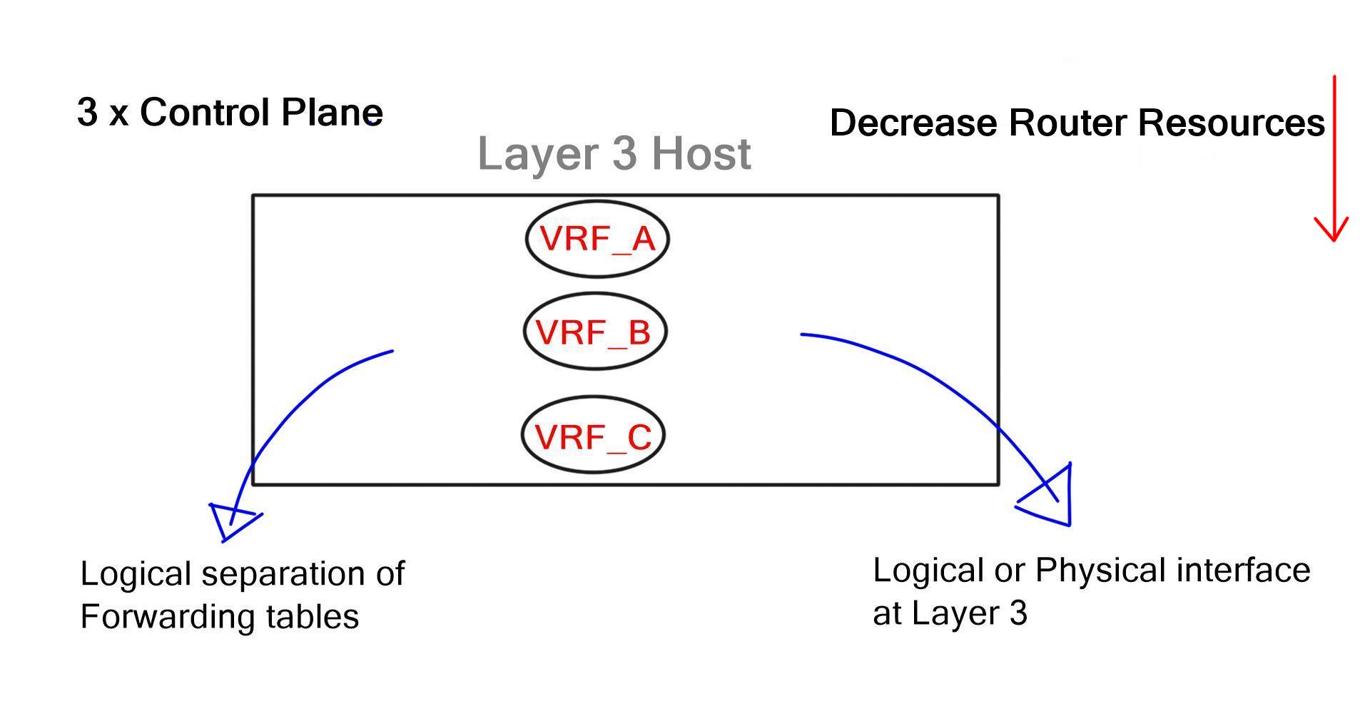
While VLANs provide logical separation at Layer 2, virtual routing and forwarding (VRF) instances provide separation at Layer 3. Layer 2 VLAN can now map to Layer 3 VRF instances. However, every VRF has a separate control plane and configuration completed on a hop-by-hop basis. Individual VRFs with separate control planes from individual routing protocol neighbor relationships, hamper router performance.

VIPTELA VRF
VRF Separation

MPLS/VPNs overcome hop-by-hop configurations to allow segmentation. This enables physically divided business units to be logically divided without the need for individual hop-by-hop VPN configurations throughout the network. Instead, only the PE edge routers carry VPN information. This supports a variety of topologies such as hub and spoke, partial mesh, or any to any connectivity. While MPLS/VPNs have their benefits, they also introduce a unique set of challenges.

MPLS Challenges

MPLS topologies, once provisioned, are difficult to modify. This is due to the fact that all the impacted PE routers have to be re-provisioned with each new policy change. In this way, MPLS topologies are similar to the brick foundation of a house. Once the foundation is laid, it’s hard to make changes to the original structure without starting over.

Most modifications to VPN site topologies must go through an additional design phase. If a Wide Area Network (WAN) is outsourced to a carrier, it would require service provider intervention with additional design & provisioning activities. A simple task such as mapping application subnets to new or existing RT may involve onsite consultants, new high-level design, and configuration templates which would have to be applied by provisioning teams. Service provider provisioning and design activities are not free and usually have long lead times.

Some flexible Edge MPLS designs do exist. For example, community tagging and matching. During the design phase, the customer and service provider agree on predefined communities. Once these are set by the customer (attached to a prefix) they are matched by the provider to perform a certain type of traffic engineering (TE).

While community tagging and matching do provide some degree of flexibility and are commonly used, it remains a fixed, predefined configuration. Any subsequent design changes may still require service provider intervention.

Applications Must Fit A Certain Topology

The model forces applications to fit into a network topology that is already built and designed. It lacks the flexibility for the network to keep up with changing business needs. What’s needed is a way to map application requirements to the network. Applications are exploding and each has a variety of operational and performance requirements, which should be met in isolation.

Viptela SD-WAN & Topologies Per Application

By moving from hardware and diverse control planes to software & unified control planes at the WAN edge, SD-WAN evolves the fixed network approach. It abstracts the details of WAN; allowing application-independent topologies. SD-WAN provides segmentation between traffic sets and could be a good way to help create on-demand applications. Essentially, creating multiple on-demand topologies per application or group of applications. Each application can have its own topology and dynamically changing policies which are managed by a central controller.

The application controls the network design.

SD-WAN - Application flows
SD-WAN – Application flows

In SD-WAN, the central controller is hosted and managed by the customer, not a service provider. This enables the WAN to be segmented for each application at the customer’s discretion. For example, PCI traffic can be transported using an overlay specifically designed for compliance via Provider A. Meanwhile, ATM traffic can travel over the same provider network but using an overlay specifically designed for ATM. Meanwhile, each overlay can have different performance characteristics for path failover so that if the network does not reach a certain round-trip time (RTT) metric, traffic can reroute over another path. The customer has complete control over what application goes where and has the power to change policies on the fly.

The SDN controller, which acts as the brain, can set different applications to run over different paths based on business requirements and performance SLAs, not on a fixed topology. Each topology is segmented from the others and applications can share or have independent on-demand topologies. SD-WAN dramatically accelerates the time it takes to adapt the network to changing business needs.

SD-WAN Topologies

The network topologies can be depicted either physically or logically. Common topologies such as Star, Mesh, Full, and Ring are categorized under a centralized or decentralized function. In a physical world, these topologies are fixed and cannot be automatically changed. Logical topologies may also be hindered by physical device footprints.

In contrast, SD-WAN fully supports the coexistence of multiple application topologies regardless of existing physical footprints. For example, Lync message and video subscriptions may require different path topologies with separate SLAs. Messages may travel over low-cost links while video requires lower latency transports.

SD-WAN can flexibly cater to the needs of any type of application. In retail environments, store-specific applications may require a hub and spoke topology for authentication or security requirements. Surveillance systems may require full mesh topology. Guest Wi-fi may require local Internal access compared to normal user traffic that is scrubbed via a hub site. This per-application topology gives designers better control over the network. Viptela SD-WAN endpoints support multiple logical segments (regardless of the existing physical network), each of which can use a unique topology (full mesh, hub and spoke, ring) and be managed via its own policy.

Viptela SD-WAN: Predictable Application Performance

Obtaining predictable services is achieved by understanding the per-application requirements and routing appropriately.

Traditional MPLS WANs, offer limited fabric visibility. For example, providers allow enterprises to perform traceroute and pings, but bits-per-second is a primitive and unreliable method for measuring end-to-end application performance. Instead, WANs should be monitored at multiple layers, not just at the packet layer.

If a service provider is multiple autonomous systems (AS) away and experiencing performance problems, these cannot be addressed and detected using traditional distance-vector methods. This makes it impossible to route around problems and detect transitory oscillations. If errors on a transit path exist, a way must exist to penalize those paths.

Currently, there’s no way to detect when a remote network on the Internet is experiencing brownouts. Since the routing protocol is still operating, the best path does not change as neighbors might still be up. Routing should exist at the transport and application layer, and monitor both application flows and transactions. SD-WAN provides this function and delivers visibility at the device, transport, and application layer for insight into how the network is performing at any given time. This makes it possible to react to transitory failures before they can impact users.

“This post is sponsored by Viptela, an SD-WAN company. All thoughts and opinions expressed are the authors”


viptela1

Viptela Software Defined WAN (SD-WAN)


viptela sd wan

Viptela SD WAN

Why can’t enterprise networks scale like the Internet? What if you could virtualize the entire network?

Wide Area Network (WAN) connectivity models follow a hybrid approach, and companies may have multiple types – MPLS and the Internet. For example, branch A has remote access over the Internet, while branch B employs private MPLS connectivity. Internet and MPLS have distinct connectivity models, and different types of overlay exist for the Internet and MPLS-based networks.

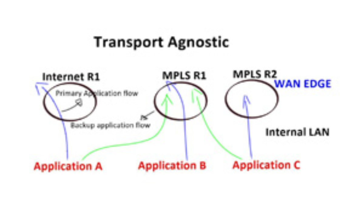
The challenge is to combine these overlays automatically and provide a transport-agnostic overlay network. The data consumption model in enterprises is shifting. Around 70% of data is; now Internet-bound, and it is expensive to trombone traffic from defined DMZ points. Customers are looking for topological flexibility, causing a shift in security parameters. Topological flexibility forces us to rethink WAN solutions for tomorrow’s networks and leads towards Viptela SD-WAN.


Before you proceed, you may find the following helpful:

  1. SD WAN Tutorial
  2. SD WAN Overlay
  3. SD WAN Security 
  4. WAN Virtualization
  5. SD-WAN Segmentation


Solution: Viptela SD WAN

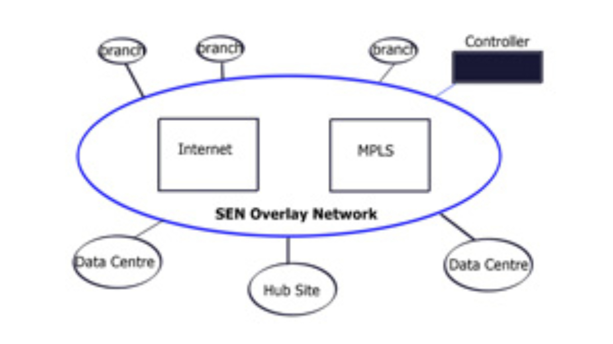
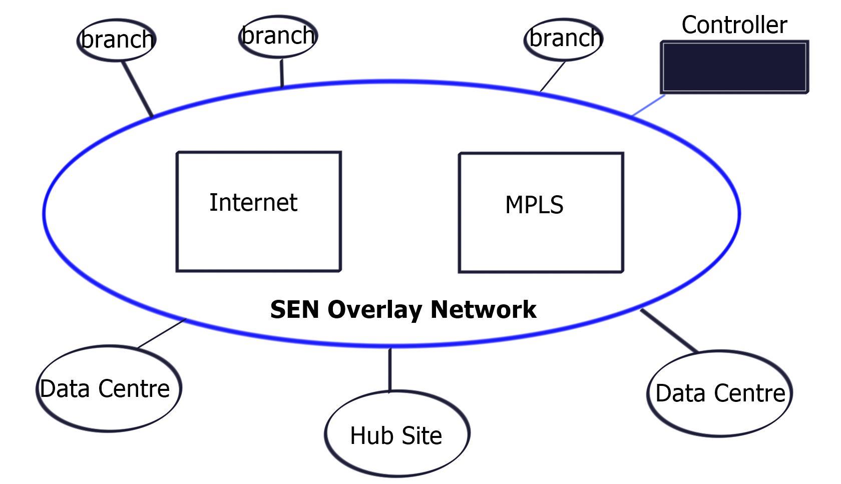
Viptela created a new overlay network called Secure Extensible Network (SEN) to address these challenges. For the first time, encryption is built into the solution. Security and routing are combined into one solution. Enables you to span environments, anywhere-to-anywhere in a secure deployment. This type of architecture is not possible with today’s traditional networking methods.

Founded in 2012, Viptela is a Virtual Private Network (VPN) company utilizing concepts of Software Defined Networking (SDN) to transform end-to-end network infrastructure. Based in San Jose, they are developing an SDN Wide Area Network (WAN) product offering any-to-any connectivity with features such as application-aware routing, service chaining, virtual Demilitarized Zone (DMZ), and weighted Equal Cost Multipath (ECMP) operating on different transports.

The key benefit of Viptela is any-to-any connectivity product offering. Connectivity was previously found in Multiprotocol Label Switching (MPLS) networks. They purely work on the connectivity model and not security frameworks. They can, however, influence-traffic paths to and from security services.

Viptela sd wan


Ubiquitous data plane

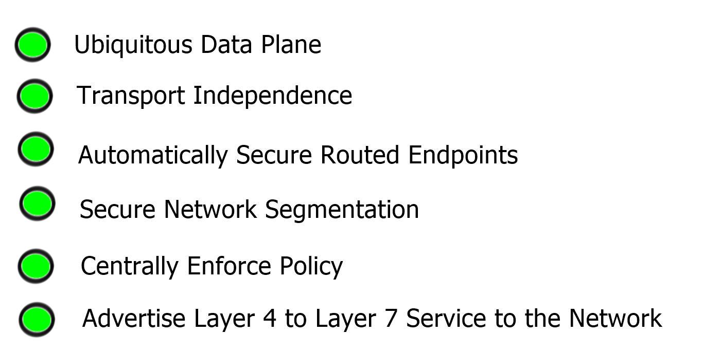
MPLS was attractive because it had a single control plane and a ubiquitous data plane. As long as you are in the MPLS network, connection to anyone is possible. Granted, you have the correct Route Distinguisher (RD) and Route Target (RT) configurations. But why can’t you take this model to Wide Area Network? Invent a technology that can create a similar model and offer ubiquitous connectivity regardless of transport type ( Internet, MPLS ).


Why Viptela SDN WAN?

The business today wants different types of connectivity modules. When you map service to business logic, the network/service topology is already laid out. It’s defined. Services have to follow this topology. Viptela is changing this concept by altering the data and control plane connectivity model using SDN to create an SDN WAN technology.

SDN is all about taking intensive network algorithms out of the hardware. Previously, in traditional networks, this was in individual hardware devices using control plane points in the data path. As a result, control points may become congested (for example – OSPF max neighbors reached). Customers lose capacity on the control plane front but not on the data plane. SDN is moving the intensive computation to off-the-shelf servers. MPLS networks attempt to use the same concepts with Route-Reflector (RR) designs.

They started to move route reflectors off the data plane to compute the best-path algorithms. Route reflectors can be positioned anywhere in the network and do not have to sit on the data path. Controller-based SDN approach, you are not embedding the control plane in the network. The controller is off the path. Now, you can scale out and SDN frameworks centrally provision and push policy down to the data plane.

Viptela can take any circuit and provide the ubiquitous connectivity MPLS provided, but now, it’s based on a policy with a central controller. Remote sites can have random transport methods. One leg could be the Internet, and the other could be MPLS. As long as there is an IP path between endpoint A and the controller, Viptela can provide the ubiquitous data plane.


Viptela SD WAN and Secure Extensible Network (SEN)

Managed overlay network

If you look at the existing WAN, it is two-part: routing and security. Routing connects sites, and security secures transmission. We have too many network security and policy configuration points in the current model. SEN allows you to centralize control plane security and routing, resulting in data path fluidity. The controller takes care of routing and security decisions.

It passes the relevant information between endpoints. Endpoints can pop up anywhere in the network. All they have to do is set up a control channel for the central controller. This approach does not build excessive control channels, as the control channel is between the controller and endpoints. Not from endpoint to endpoint. The data plane can flow based on the policy in the center of the network.

Viptela SD WAN


Viptela SD WAN: Deployment considerations

Deployment of separate data plane nodes at the customer site is integrated into existing infrastructure at Layer 2 or 3. So you can deploy incrementally, starting with one node and ending with thousands. It is so scalable because it is based on routed technology. The model allows you to deploy, for example, a guest network and then integrate it further into your network over time. Internally they use Border Gateway Protocol (BGP). One the data plane, they use standard IPSec between endpoints. It also works over Network Address Translation (NAT), meaning IPSec over UDP.

When an attacker gets access to your network, it is easy for them to reach the beachhead and hop from one segment to another. Viptela enables per-segment encryption, so even if they get to one segment, they will not be able to jump to another. Key management on a global scale has always been a challenge. Viptela solves this with a propitiatory distributed manager based on a priority system. Currently, their key management solution is not open to the industry.


SDN controller

You have a controller and VPN termination points i.e data plane points. The controller is the central management piece that assigns the policy. Data points are modules that are shipped to customer sites. The controller allows you to dictate different topologies for individual endpoint segments. Similar to how you influence-routing tables with RT in MPLS.

The control plane is at the controller.


Data plane module

Data plane modules are located at the customer site. They connect this data plane module, which could be a PE hand-off to the internal side of the network. The data plane module must be in the data plane path on the customer site. Internal side, they discover the routing protocols and participate in prefix learning. At Layer 2, they discover the VLANs. Their module can either be the default gateway or perform the router neighbor relationship function. WAN side, data plane module registers uplink IP address to WAN controller/orchestration system. The controller builds encrypted tunnels between the data endpoints. The encrypted control channels are only needed when you build over untrusted third parties.

If the problem occurs with controller connectivity, the on-site module can stop being the default gateway and usually participate in Layer 3 forwarding for existing protocols. It backs off from being the primary router for off-net traffic. It’s like creating VRF for different businesses and default routes for each VRF with a single peering point to the controller; Policy-Based Routing (PBR) for each VRF for data plane activity. The PBR is based on information coming from the controller. Each control segment can have a separate policy (for example – modifying the next hop). From a configuration point of view, you need an IP on the data plane module and the remote controller IP. The controller pushes down the rest.


  • Viptela SD WAN: Use cases

For example, you have a branch office with three distinct segments, and you want each endpoint to have its independent topology. The topology should be service driven, and the service should not follow existing defined topology. Each business should depict how they want their business to connect to the network team should not say this is how the topology is, and you must obey our topology.

From a carrier’s perspective, they can expand their MPLS network to areas they do not have a physical presence. And bring customers with this secure overlay to their closest pop where they have an MPLS peering. MPLS providers can expand their footprint to areas where they do not have service. If MPLS has customers in region X and wants to connect to the customer in region Y, they can use Viptela. Having those different data plane endpoints through a security framework would be best before entering the MPLS network.

Viptela allows you to steer traffic based on the SLA requirements of the application, aka Application-Aware Routing. For example, if you have two sites with dual connectivity to MPLS and Internet, data plane modules (located at customer sites) nodes can steer traffic over either the MPLS or Internet transport based on end-to-end latency or drops. They do this by maintaining the real-time loss, latency, and jitter characteristics and then applying policies on the centralized controller. As a result, critical traffic is always steered to the most reliable link. This architecture can scale to 1000 nodes in a full mesh topology.


viptela sd wan