The ACI Fabric
Cisco ACI is a software-defined networking (SDN) solution that integrates with software and hardware. With the ACI, we can create software policies and use hardware for forwarding, an efficient and highly scalable approach offering better performance. The hardware for ACI is based on the Cisco Nexus 9000 platform product line. The APIC centralized policy controller drives the software, which stores all configuration and statistical data.
–The Cisco Nexus Family–
To build the ACI underlay, you must exclusively use the Nexus 9000 family of switches. You can choose from modular Nexus 9500 switches or fixed 1U to 2U Nexus 9300 models. Specific models and line cards are dedicated to the spine function in ACI fabric; others can be used as leaves, and some can be used for both purposes. You can combine various leaf switches inside one fabric without any limitations.
a) Cisco ACI Fabric: Cisco ACI’s foundation lies in its fabric, which forms the backbone of the entire infrastructure. The ACI fabric comprises leaf switches, spine switches, and the application policy infrastructure controller (APIC). Each component ensures a scalable, agile, and resilient network.
b) Leaf Switches: Leaf switches serve as the access points for endpoints within the ACI fabric. They provide connectivity to servers, storage devices, and other network devices. With their high port density and advanced features, such as virtual port channels (vPCs) and fabric extenders (FEX), leaf switches enable efficient and flexible network designs.
c) Spine Switches: Spine switches serve as the core of the ACI fabric, providing high-bandwidth connectivity between the leaf switches. They use a non-blocking, multipath forwarding mechanism to ensure optimal traffic flow and eliminate bottlenecks. With their modular design and support for advanced protocols like Ethernet VPN (EVPN), spine switches offer scalability and resiliency.
d) Application Policy Infrastructure Controller (APIC): At the heart of Cisco ACI is the APIC, a centralized management and policy control plane. The APIC acts as a single control point, simplifying network operations and enabling policy-based automation. It provides a comprehensive view of the entire fabric, allowing administrators to define and enforce policies across the network.
e) Integration with Virtualization and Cloud Environments: Cisco ACI seamlessly integrates with virtualization platforms such as VMware vSphere and Microsoft Hyper-V and cloud environments like Amazon Web Services (AWS) and Microsoft Azure. This integration enables consistent policy enforcement and visibility across physical, virtual, and cloud infrastructures, enhancing agility and simplifying operations.
Cisco ACI — Policy‑Driven, Application‑Centric Networking
Cisco ACI (Application Centric Infrastructure) is Cisco’s flagship data‑center fabric built around policy‑driven automation, centralized control, and application‑aware networking. Instead of configuring individual switches, ACI abstracts the network into application policies, endpoint groups, and contracts. This creates a programmable, intent‑based fabric where the network automatically aligns with application requirements. Data analytics strengthens ACI by providing visibility into fabric health, policy behavior, endpoint movement, and application flows, ensuring that the fabric remains consistent, secure, and optimized.
Policy Model — Endpoint Groups, Contracts, and Intent
ACI’s core innovation is its policy model:
- Endpoint Groups (EPGs) define logical groupings of workloads
- Contracts define how EPGs communicate
- Application Network Profiles (ANPs) map application tiers to policies
- Tenants provide multi‑domain isolation
This model replaces traditional VLANs, ACLs, and manual segmentation with intent‑based policies. Analytics enhances this by identifying unused contracts, misaligned EPGs, shadow policies, and unexpected east‑west flows. With analytics, ACI’s policy model becomes adaptive and identity‑aware rather than static.
Fabric Architecture — Spine‑Leaf, VXLAN, and Distributed Control
ACI uses a spine‑leaf architecture with VXLAN overlays and a centralized policy controller (APIC). The fabric provides:
- consistent forwarding across all leaf switches
- distributed anycast gateways
- scalable multi‑tenant segmentation
- automated endpoint learning
Analytics correlates fabric telemetry—routing updates, VXLAN behavior, endpoint mobility, and link performance—to detect anomalies such as asymmetric routing, endpoint flapping, or misconfigured policies. This ensures the fabric remains stable and predictable even under dynamic workloads.
Security and Microsegmentation in ACI
ACI provides built‑in microsegmentation through EPGs and contracts. Security becomes application‑centric rather than IP‑centric. Analytics enhances ACI security by monitoring:
- unusual endpoint movement
- abnormal contract usage
- unexpected east‑west communication
- privilege escalation inside application tiers
This transforms ACI into a Zero Trust‑aligned data‑center fabric where segmentation is continuously validated and enforced.
Operational Visibility — Telemetry, Health Scores, and Assurance
ACI includes extensive telemetry and health scoring across:
- fabric nodes
- policies
- endpoints
- application flows
Analytics consumes this telemetry to provide deeper insights into performance, security, and policy alignment. Tools like ACI AppDynamics integration, Nexus Dashboard Insights, and fabric assurance engines use analytics to detect drift, highlight anomalies, and recommend remediation. ACI becomes a self‑optimizing fabric driven by real‑time intelligence.
ACI in Hybrid and Multi‑Cloud Architectures
ACI extends beyond the data center into cloud environments through ACI Anywhere and Cloud ACI. Policies can be pushed to AWS, Azure, and GCP, creating a unified segmentation and security model across hybrid environments. Analytics ensures consistency across on‑prem and cloud fabrics, detecting mismatches, drift, and cross‑cloud anomalies. This creates a seamless, policy‑driven hybrid architecture.
–ACI Architecture: Spine and Leaf–
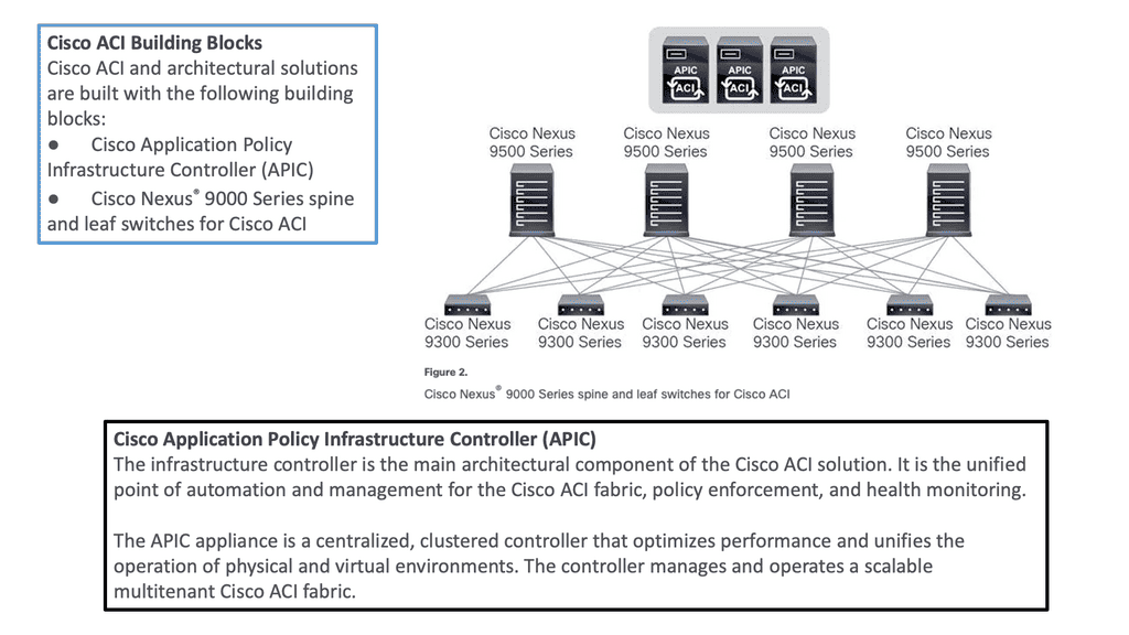
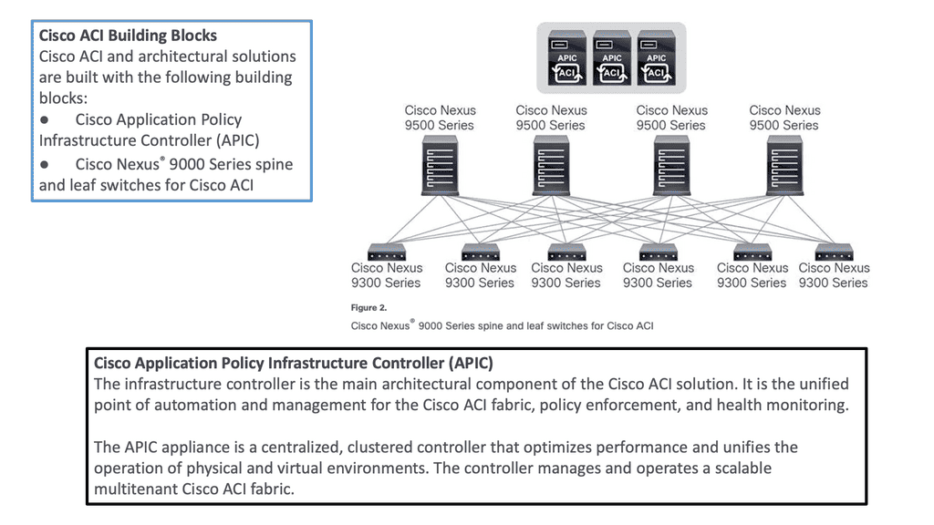
To be used as ACI spines or leaves, Nexus 9000 switches must be equipped with powerful Cisco CloudScale ASICs manufactured using 16-nm technology. The following figure shows the Cisco ACI based on the Nexus 9000 series. Cisco Nexus 9300 and 9500 platform switches support Cisco ACI. As a result, organizations can use them as spines or leaves to utilize an automated, policy-based systems management approach fully.
**Hardware-based Underlay**
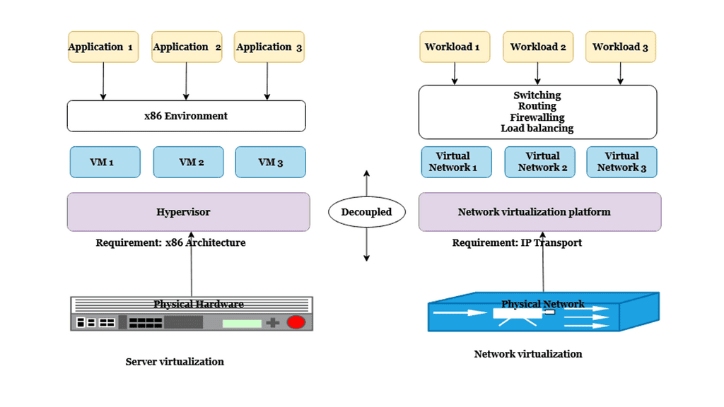
Server virtualization helped by decoupling workloads from the hardware, making the compute platform more scalable and agile. However, the server is not the main interconnection point for network traffic. So, we need to look at how we could virtualize the network infrastructure similarly to the agility gained from server virtualization.
**Mapping Network Endpoints**
This is carried out with software-defined networking and overlays that could map network endpoints and be spun up and down as needed without human intervention. In addition, the SDN architecture includes an SDN controller and an SDN network that enables an entirely new data center topology.
**Specialized Forwarding Chips**
In ACI, hardware-based underlay switching offers a significant advantage over software-only solutions due to specialized forwarding chips. Furthermore, thanks to Cisco’s ASIC development, ACI brings many advanced features, including security policy enforcement, microsegmentation, dynamic policy-based redirect (inserting external L4-L7 service devices into the data path), or detailed flow analytics—besides the vast performance and flexibility.
Introduction to Leaf and Spine
The Cisco SDN ACI works with a Clos architecture, a fully meshed ACI network. Based on a spine leaf architecture. As a result, every Leaf is physically connected to every Spine, enabling traffic forwarding through non-blocking links. Physically, a leaf switch set creates a leaf layer attached to the spines in a full BIPARTITE graph. This means that each Leaf is connected to each Spine, and each Spine is connected to each Leaf.
The ACI uses a horizontally elongated Leaf and Spine architecture with one hop to every host in an entirely messed ACI fabric, offering good throughput and convergence needed for today’s applications.
The ACI fabric: Does Not Aggregate Traffic
A key point in the spine-and-leaf design is the fabric concept, like a stretch network. One of the core ideas around a fabric is that it does not aggregate traffic. This does increase data center performance along with a non-blocking architecture. With the spine-leaf topology, we are spreading a fabric across multiple devices.
Required: Increased Bandwidth Available
The result of the fabric is that each edge device has the total bandwidth of the fabric available to every other edge device. This is one big difference from traditional data center designs; we aggregate the traffic by either stacking multiple streams onto a single link or carrying the streams serially.
Challenge: Oversubscription
With the traditional 3-tier design, we aggregate everything at the core, leading to oversubscription ratios that degrade performance. With the ACI Leaf and Spine design, we spread the load across all devices with equidistant endpoints, allowing us to carry the streams parallel.
Required: Routed Multipathing
Then, we have horizontal scaling load balancing. Load balancing with this topology uses multipathing to achieve the desired bandwidth between the nodes. Even though this forwarding paradigm can be based on Layer 2 forwarding ( bridging) or Layer 3 forwarding ( routing), the ACI leverages a routed approach to the Leaf and Spine design, and we have Equal Cost Multi-Path (ECMP) for both Layer 2 and Layer 3 traffic.
**Overlay and Underlay Design**
Mapping Traffic:
So you may be asking how we can have Layer 3 routed core and pass Layer 2 traffic. This is done using the overlay, which can map different traffic types to other overlays. So, we can have Layer 2 traffic mapped to an overlay over a routed core.
L3 active-active links: ACI links between the Leaf and the Spine switches are L3 active-active links. Therefore, we can intelligently load balance and traffic steer to avoid issues. We don’t need to rely on STP to block links or involve STP in fixing the topology.
Challenge: IP – Identity & Location
When networks were first developed, there was no such thing as an application moving from one place to another while it was in use. So, the original architects of IP, the communication protocol used between computers, used the IP address to indicate both the identity of a device connected to the network and its location on the network. Today, in the modern data center, we need to be able to communicate with an application or application tier, no matter where it is.
Required: Overlay Encapsulation
One day, it may be in location A and the next in location B, but its identity, which we communicate with, is the same on both days. An overlay is when we encapsulate an application’s original message with the location to which it needs to be delivered before sending it through the network. Once it arrives at its final destination, we unwrap it and deliver the original message as desired.
The identities of the devices (applications) communicating are in the original message, and the locations are in the encapsulation, thus separating the place from the identity. This wrapping and unwrapping is done on a per-packet basis and, therefore, must be done quickly and efficiently.
**Overlay and Underlay Components**
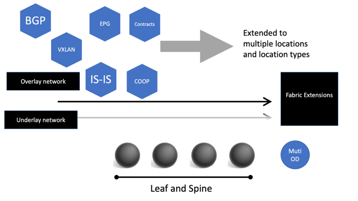
The Cisco SDN ACI has an overlay and underlay concept, which forms a virtual overlay solution. The role of the underlay is to glue together devices so the overlay can work and be built on top. So, the overlay, which is VXLAN, runs on top of the underlay, which is IS-IS. In the ACI, the IS-IS protocol provides the routing for the overlay, which is why we can provide ECMP from the Leaf to the Spine nodes. The routed underlay provides an ECMP network where all leaves can access Spine and have the same cost links.
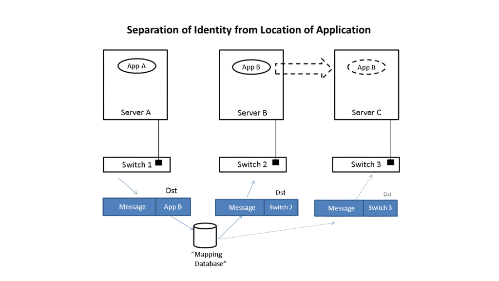
Underlay & Overlay Interaction
Example:
Let’s take a simple example to illustrate how this is done. Imagine that application App-A wants to send a packet to App-B. App-A is located on a server attached to switch S1, and App-B is initially on switch S2. When App-A creates the message, it will put App-B as the destination and send it to the network; when the message is received at the edge of the network, whether a virtual edge in a hypervisor or a physical edge in a switch, the network will look up the location of App-B in a “mapping” database and see that it is attached to switch S2.
It will then put the address of S2 outside of the original message. So, we now have a new message addressed to switch S2. The network will forward this new message to S2 using traditional networking mechanisms. Note that the location of S2 is very static, i.e., it does not move, so using traditional mechanisms works just fine.
Upon receiving the new message, S2 will remove the outer address and thus recover the original message. Since App-B is directly connected to S2, it can easily forward the message to App-B. App-A never had to know where App-B was located, nor did the network’s core. Only the edge of the network, specifically the mapping database, had to know the location of App-B. The rest of the network only had to see the location of switch S2, which does not change.
Let’s now assume App-B moves to a new location switch S3. Now, when App-A sends a message to App-B, it does the same thing it did before, i.e., it addresses the message to App-B and gives the packet to the network. The network then looks up the location of App-B and finds that it is now attached to switch S3. So, it puts S3’s address on the message and forwards it accordingly. At S3, the message is received, the outer address is removed, and the original message is delivered as desired.
App-A did not track App-B’s movement at all. App-B’s address identified It, while the switch’s address, S2 or S3, identified its location. App-A can communicate freely with App-B no matter where It is located, allowing the system administrator to place App-B in any area and move it as desired, thus achieving the flexibility needed in the data center.
Multicast Distribution Tree (MDT)
We have a Multicast Distribution Tree MDT tree on top that is used to forward multi-destination traffic without having loops. The Multicast distribution tree is dynamically built to send flood traffic for specific protocols. Again, it does this without creating loops in the overlay network. The tunnels created for the endpoints to communicate will have tunnel endpoints. The tunnel endpoints are known as the VTEP. The VTEP addresses are assigned to each Leaf switch from a pool that you specify in the ACI startup and discovery process.
Normalize the transports
VXLAN tunnels in the ACI fabric normalize the transports in the ACI network. Therefore, traffic between endpoints can be delivered using the VXLAN tunnel, resulting in any transport network regardless of the device connecting to the fabric.
So, using VXLAN in the overlay enables any network, and you don’t need to configure anything special on the endpoints for this to happen. The endpoints that connect to the ACI fabric do not need special software or hardware. The endpoints send regular packets to the leaf nodes they are connected to directly or indirectly. As endpoints come online, they send traffic to reach a destination.
Bridge Domains and VRF
Therefore, the Cisco SDN ACI under the hood will automatically start to build the VXLAN overlay network for you. The VXLAN network is based on the Bridge Domain (BD), or VRF ACI constructs deployed to the leaf switches. The Bridge Domain is for Layer 2, and the VRF is for Layer 3. So, as devices come online and send traffic to each other, the overlay will grow in reachability in the Bridge Domain or the VRF.
Direct host routing for endoints
Routing within each tenant, VRF is based on host routing for endpoints directly connected to the Cisco ACI fabric. For IPv4, the host routing is based on the /32, giving the ACI a very accurate picture of the endpoints. Therefore, we have exact routing in the ACI. In conjunction, we have a COOP database that runs on the Spines and offers remarkably optimized fabric to know where all the endpoints are located.
To facilitate this, every node in the fabric has a TEP address, and we have different types of TEPs depending on the device’s role. The Spine and the Leaf will have TEP addresses but will differ from each other.
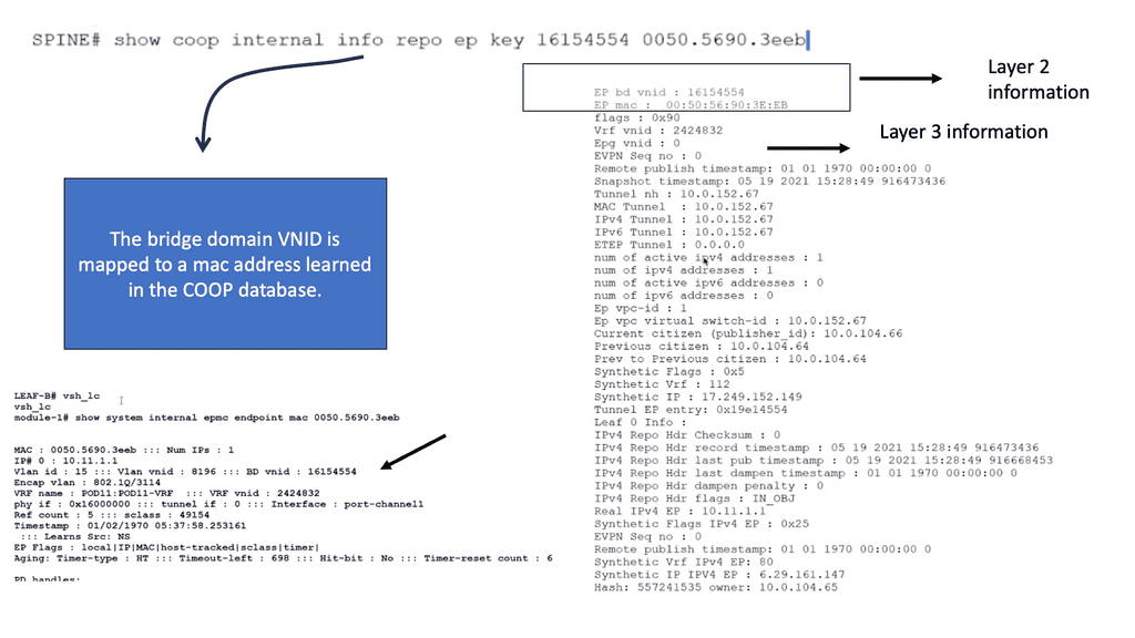
The VTEP and PTEP
The Leaf’s nodes are the Virtual Tunnel Endpoints (VTEP), which are also known as the physical tunnel endpoints (PTEP) in ACI. These PTEP addresses represent the “WHERE” in the ACI fabric where an endpoint lives. Cisco ACI uses a dedicated VRF and a subinterface of the uplinks from the Leaf to the Spines as the infrastructure to carry VXLAN traffic. In Cisco ACI terminology, the transport infrastructure for VXLAN traffic is known as Overlay-1, which is part of the tenant “infra.”
**The Spine TEP**
The Spines also have a PTEP and an additional proxy TEP, which are used for forwarding lookups into the mapping database. The Spines have a global view of where everything is, which is held in the COOP database synchronized across all Spine nodes. All of this is done automatically for you.
**Anycast IP Addressing**
For this to work, the Spines have an Anycast IP address known as the Proxy TEP. The Leaf can use this address if they do not know where an endpoint is, so they ask the Spine for any unknown endpoints, and then the Spine checks the COOP database. This brings many benefits to the ACI solution, especially for traffic optimizations and reducing flooded traffic in the ACI. Now, we have an optimized fabric for better performance.
The ACI optimizations
**Mouse and elephant flow**
This provides better performance for load balancing different flows. For example, in most data centers, we have latency-sensitive flows, known as mouse flows, and long-lived bandwidth-intensive flows, known as elephant flows.
The ACI has more precisely load-balanced traffic using algorithms that optimize mouse and elephant flows and distribute traffic based on flow lets: flow let load-balancing. Within a Leaf, Spine latency is low and consistent from port to port.
The max latency of a packet from one port to another in the architecture is the same regardless of the network size. So you can scale the network without degrading performance. Scaling is often done on a POD-by-POD basis. For more extensive networks, each POD would be its Leaf and Spine network.
**ARP optimizations: Anycast gateways**
The ACI comes by default with a lot of traffic optimizations. Firstly, instead of using an ARP and broadcasting across the network, that can hamper performance. The Leaf can assume that the Spine will know where the destination is ( and it does via the COOP database ), so there is no need to broadcast to everyone to find a destination.
If the Spine knows where the endpoint is, it will forward the traffic to the other Leaf. If not, it will drop it.
**Fabric anycast addressing**
This again adds performance benefits to the ACI solution as the table sizes on the Leaf switches can be kept smaller than they would if they needed to know where all the destinations were, even if they were not or never needed to communicate with them. On the Leaf, we have an Anycast address too.
These fabric Anycast addresses are available for Layer 3 interfaces. On the Leaf ToR, we can establish an SVI that uses the same MAC address on every ToR; therefore, when an endpoint needs to route to a ToR, it doesn’t matter which ToR you use. The Anycast Address is spread across all ToR leaf switches.
**Pervasive gateway**
Now we have predictable latency to the first hop, and you will use the local route VRF table within that ToR instead of traversing the fabric to a different ToR. This is the Pervasive Gateway feature that is used on all Leaf switches. The Cisco ACI has many advanced networking features, but the pervasive gateway is my favorite. It does take away all the configuration mess we had in the past.
ACI Cisco: Integrations
- Routing Control Platform
Then came along Cisco SDN ACI, the ACI Cisco, which operates differently from the traditional data center with an application-centric infrastructure. The Cisco application-centric infrastructure achieves resource elasticity with automation through standard policies for data center operations and consistent policy management across multiple on-premises and cloud instances.
- Extending & Integrating the fabric
What makes the Cisco ACI interesting is its several vital integrations. I’m not talking about extending the data center with multi-pod and multi-site, for example, with AlgoSec, Cisco AppDynamics, and SD-WAN. AlgoSec enables secure application delivery and policy across hybrid network estates, while AppDynamic lives in a world of distributed systems Observability. SD-WAN enabled path performance per application with virtual WANs.
Cisco Multi-Pod Design
Cisco ACI Multi-Pod is part of the “Single APIC Cluster / Single Domain” family of solutions, as a single APIC cluster is deployed to manage all the interconnected ACI networks. These separate ACI networks are named “pods,” Each looks like a regular two-tier spine-leaf topology. The same APIC cluster can manage several pods, and to increase the resiliency of the solution, the various controller nodes that make up the cluster can be deployed across different pods.
ACI Cisco and AlgoSec
With AlgoSec integrated with the Cisco ACI, we can now provide automated security policy change management for multi-vendor devices and risk and compliance analysis. The AlgoSec Security Management Solution for Cisco ACI extends ACI’s policy-driven automation to secure various endpoints connected to the Cisco SDN ACI fabric.
These simplify network security policy management across on-premises firewalls, SDNs, and cloud environments. They also provide visibility into ACI’s security posture, even across multi-cloud environments.
ACI Cisco and AppDynamics
Then, with AppDynamics, we are heading into Observability and controllability. Now, we can correlate app health and network for optimal performance, deep monitoring, and fast root-cause analysis across complex distributed systems with numbers of business transactions that need to be tracked.
This will give your teams complete visibility of your entire technology stack, from your database servers to cloud-native and hybrid environments. In addition, AppDynamics works with agents that monitor application behavior in several ways. We will examine the types of agents and how they work later in this post.
ACI Cisco and SD-WAN
SD-WAN brings a software-defined approach to the WAN. These enable a virtual WAN architecture to leverage transport services such as MPLS, LTE, and broadband internet services. So, SD-WAN is not a new technology; its benefits are well known, including improving application performance, increasing agility, and, in some cases, reducing costs.
The Cisco ACI and SD-WAN integration makes active-active data center design less risky than in the past. The following figures give a high-level overview of the Cisco ACI and SD-WAN integration. For pre-information generic to SD-WAN, go here: SD-WAN Tutorial
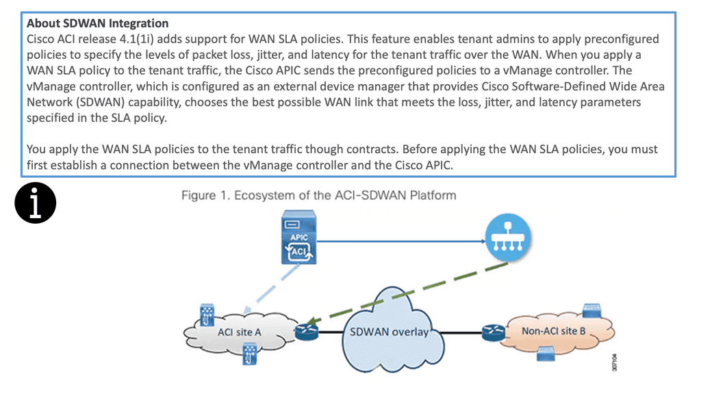
The Cisco SDN ACI with SD-WAN integration helps ensure an excellent application experience by defining application Service-Level Agreement (SLA) parameters. Cisco ACI releases 4.1(1i) and adds support for WAN SLA policies. This feature enables admins to apply pre-configured policies to specify the packet loss, jitter, and latency levels for the tenant traffic over the WAN.
When you apply a WAN SLA policy to the tenant traffic, the Cisco APIC sends the pre-configured policies to a vManage controller. The vManage controller, configured as an external device manager that provides SDWAN capability, chooses the best WAN link that meets the loss, jitter, and latency parameters specified in the SLA policy.
Openshift and Cisco SDN ACI
OpenShift Container Platform (formerly known as OpenShift Enterprise) or OCP is Red Hat’s offering for the on-premises private platform as a service (PaaS). OpenShift is based on the Origin open-source project and is a Kubernetes distribution, the defacto for container-based virtualization. The foundation of the OpenShift networking SDN is based on Kubernetes and, therefore, shares some of the same networking technology along with some enhancements, such as the OpenShift route construct.
Other data center integrations
Cisco SDN ACI has another integration with Cisco DNA Center/ISE that maps user identities consistently to endpoints and apps across the network, from campus to the data center. Cisco Software-Defined Access (SD-Access) provides policy-based automation from the edge to the data center and the cloud.
Cisco SD-Access provides automated end-to-end segmentation to separate user, device, and application traffic without redesigning the network. This integration will enable customers to use standard policies across Cisco SD-Access and Cisco ACI, simplifying customer policy management using Cisco technology in different operational domains.
OpenShift and Cisco ACI
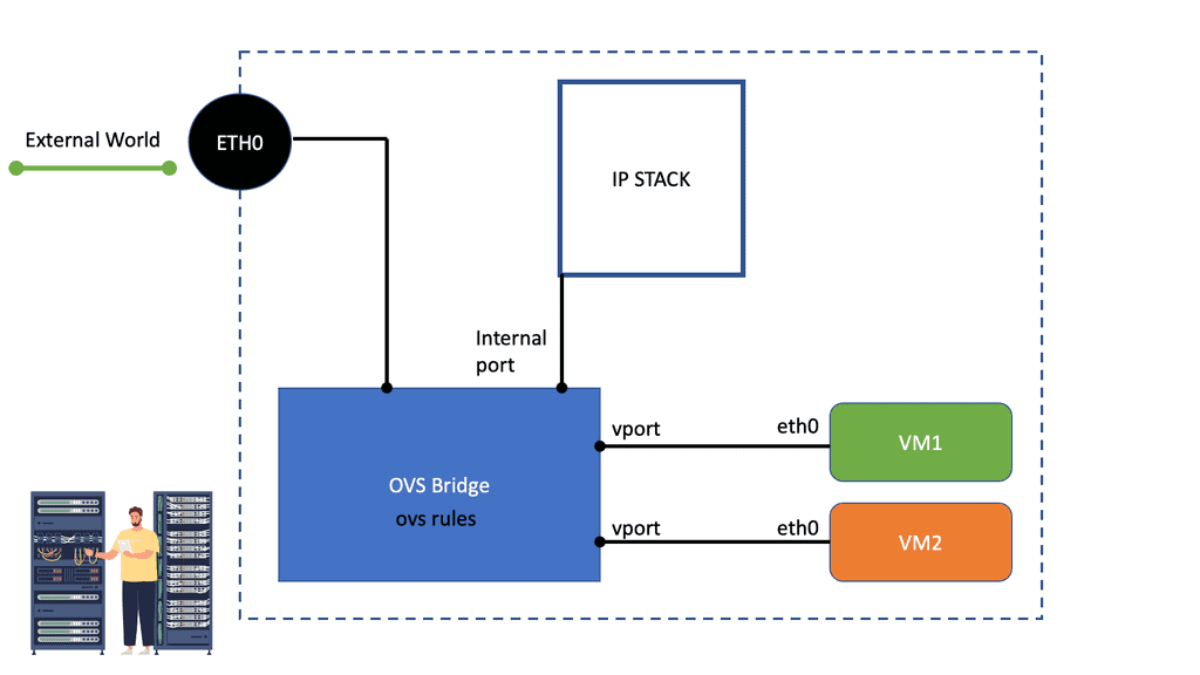
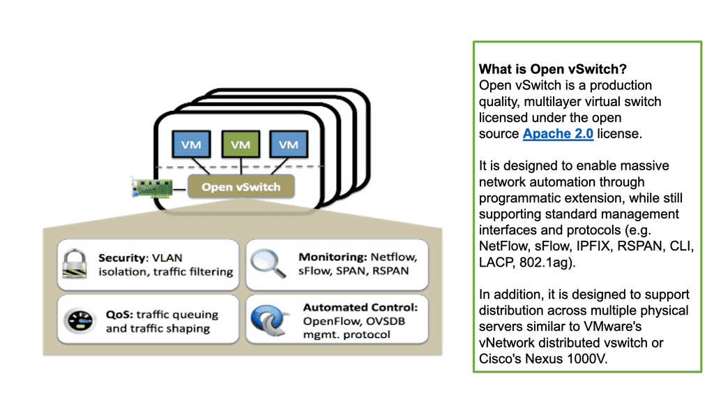
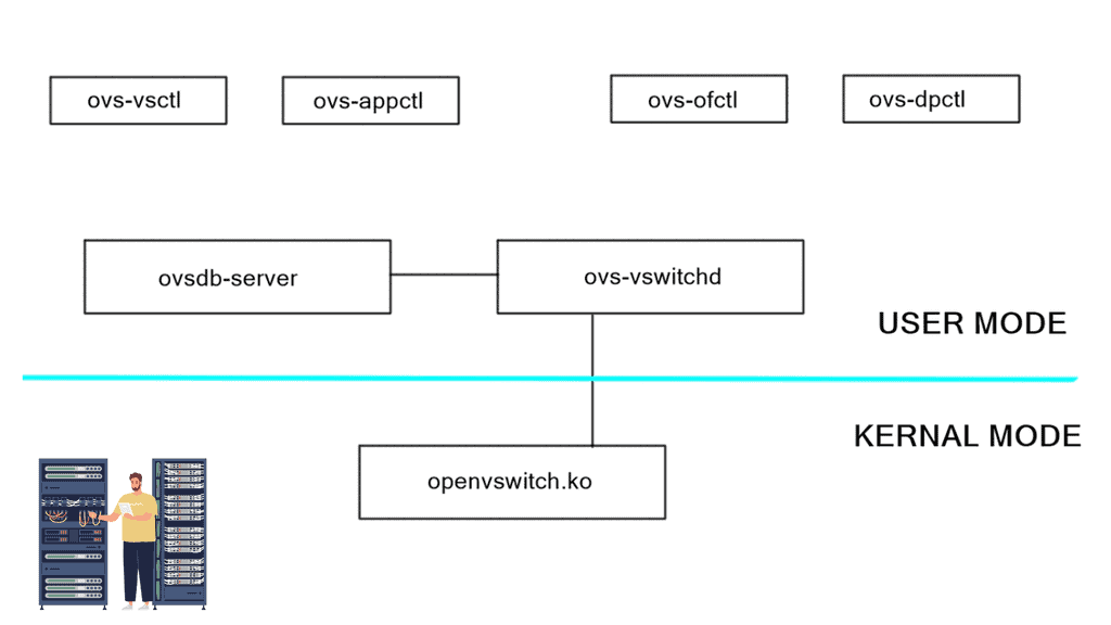
OpenShift does this with an SDN layer and enhances Kubernetes networking to create a virtual network across all the nodes. It is made with the Open Switch standard. For OpenShift SDN, this pod network is established and maintained by the OpenShift SDN, configuring an overlay network using a virtual switch called the OVS bridge. This forms an OVS network that gets programmed with several OVS rules. The OVS is a popular open-source solution for virtual switching.
OpenShift SDN plugin
We mentioned that you could tailor the virtual network topology to suit your networking requirements, which can be determined by the OpenShift SDN plugin and the SDN model you select. With the default OpenShift SDN, several modes are available. This level of SDN mode you choose is concerned with managing connectivity between applications and providing external access to them. Some modes are more fine-grained than others. The Cisco ACI plugins offer the most granular.
Integrating ACI and OpenShift platform
The Cisco ACI CNI plugin for the OpenShift Container Platform provides a single, programmable network infrastructure, enterprise-grade security, and flexible micro-segmentation possibilities. The APIC can provide all networking needs for the workloads in the cluster. Kubernetes workloads become fabric endpoints, like Virtual Machines or Bare Metal endpoints.
Cisco ACI CNI Plugin
The Cisco ACI CNI plugin extends the ACI fabric capabilities to OpenShift clusters to provide IP Address Management, networking, load balancing, and security functions for OpenShift workloads. In addition, the Cisco ACI CNI plugin connects all OpenShift Pods to the integrated VXLAN overlay provided by Cisco ACI.
Cisco SDN ACI and AppDynamics
AppDynamis overview
So, an application requires multiple steps or services to work. These services may include logging in and searching to add something to a shopping cart. These services invoke various applications, web services, third-party APIs, and databases, known as business transactions.
The user’s critical path
A business transaction is the essential user interaction with the system and is the customer’s critical path. Therefore, business transactions are the things you care about. If they start to go, your system will degrade. So, you need ways to discover your business transactions and determine if there are any deviations from baselines. This should also be automated, as learning baseline and business transitions in deep systems is nearly impossible using the manual approach.
So, how do you discover all these business transactions?
AppDynamics automatically discovers business transactions and builds an application topology map of how the traffic flows. A topology map can view usage patterns and hidden flows, acting as a perfect feature for an Observability platform.
AppDynamic topology
AppDynamics will automatically discover the topology for all of your application components. It can then build a performance baseline by capturing metrics and traffic patterns. This allows you to highlight issues when services and components are slower than usual.
AppDynamics uses agents to collect all the information it needs. The agent monitors and records the calls that are made to a service. This is from the entry point and follows executions along its path through the call stack.
Types of Agents for Infrastructure Visibility
If the agent is installed on all critical parts, you can get information about that specific instance, which can help you build a global picture. So we have an Application Agent, Network Agent, and Machine Agent for Server visibility and Hardware/OS.
- App Agent: This agent will monitor apps and app servers, and example metrics will be slow transitions, stalled transactions, response times, wait times, block times, and errors.
- Network Agent: This agent monitors the network packets, TCP connection, and TCP socket. Example metrics include performance impact Events, Packet loss, and retransmissions, RTT for data transfers, TCP window size, and connection setup/teardown.
- Machine Agent Server Visibility: This agent monitors the number of processes, services, caching, swapping, paging, and querying. Example Metrics include hardware/software interrupts, virtual memory/swapping, process faults, and CPU/DISK/Memory utilization by the process.
- Machine Agent: Hardware/OS – disks, volumes, partitions, memory, CPU. Example metrics: CPU busy time, MEM utilization, and pieces file.
Automatic establishment of the baseline
A baseline is essential, a critical step in your monitoring strategy. Doing this manually is hard, if not impossible, with complex applications. It is much better to have this done automatically. You must automatically establish the baseline and alert yourself about deviations from it.
This will help you pinpoint the issue faster and resolve it before it can be affected. Platforms such as AppDynamics can help you here. Any malicious activity can be seen from deviations from the security baseline and performance issues from the network baseline.