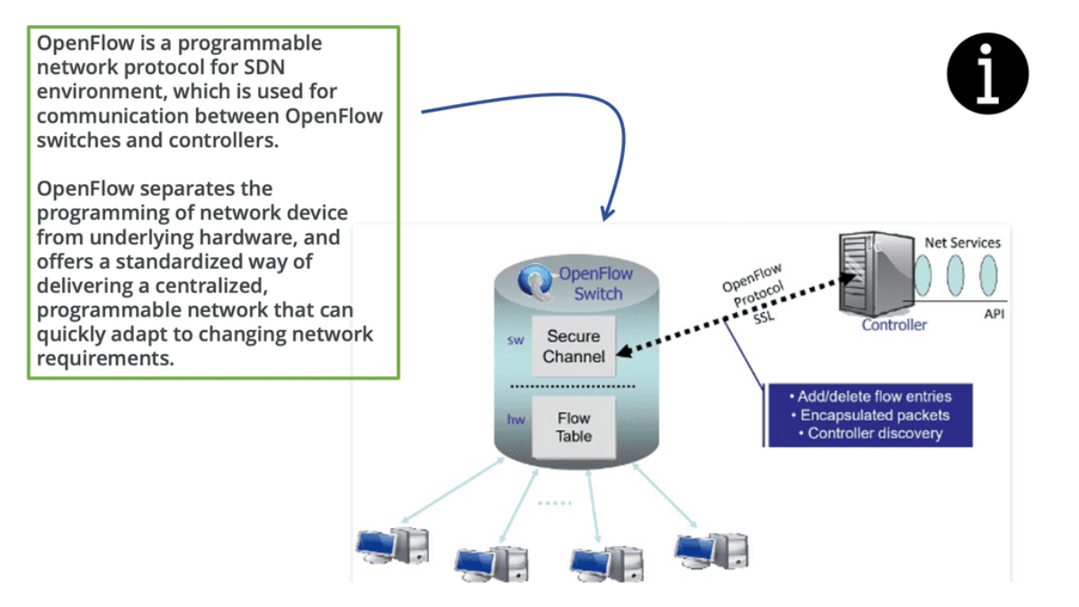
Understanding OpenFlow Protocol
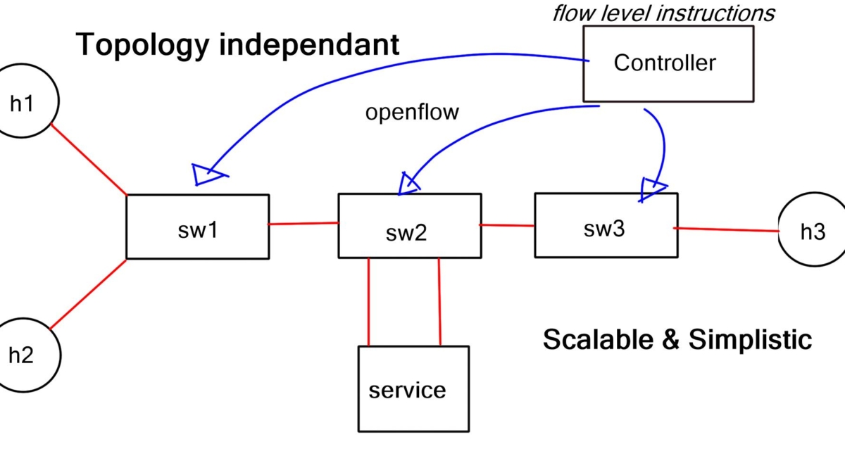
– The OpenFlow protocol is a communication standard allowing centralized control of network switches and routers. It separates the control plane from the data plane, enabling network administrators to have a holistic view of the network and make dynamic changes. Using a software-defined approach, OpenFlow opens up a realm of network management and optimization possibilities.
– OpenFlow boasts several essential features that make it a powerful tool in network management. These include flow-based forwarding, fine-grained control, and network programmability. Flow-based forwarding allows for traffic routing based on specific criteria, such as source or destination IP addresses.
– Fine-grained control enables administrators to set detailed rules and policies, ensuring optimal network performance. Network programmability allows for the customization and automation of network configurations, simplifying complex tasks.
Key Point: Flow-Based Forwarding
## Understanding the Basics of Flow-Based Forwarding
Flow-based forwarding is a method of routing network traffic based on predefined flows, which are essentially sequences of packets sharing the same attributes. Unlike traditional packet-based forwarding, which handles each packet independently, flow-based systems recognize and process flows as a single entity. This unified approach allows for more cohesive and efficient traffic management, as it can prioritize, route, and control data flows based on real-time requirements and policies.
## The Role of OpenFlow in Flow-Based Forwarding
OpenFlow is a pivotal protocol that enables flow-based forwarding by providing a standardized interface for programming network switches. It allows network administrators to define flows and enforce policies directly on the hardware, effectively separating the data plane from the control plane.
This separation empowers networks to be more adaptive and programmable, offering unprecedented levels of control over traffic behavior. OpenFlow’s ability to dynamically adjust to network conditions makes it an invaluable tool for implementing flow-based strategies across various applications.
**Key OpenFlow Benefits**
1: The adoption of the OpenFlow protocol brings numerous benefits to network environments. Firstly, it enhances network visibility and monitoring, enabling administrators to promptly identify and address potential bottlenecks or security threats.
2: Secondly, OpenFlow facilitates network flexibility and scalability, as changes can be easily implemented through centralized control. Moreover, the protocol promotes innovation by allowing new applications and services that leverage its programmability.
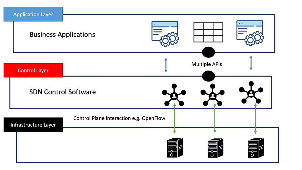
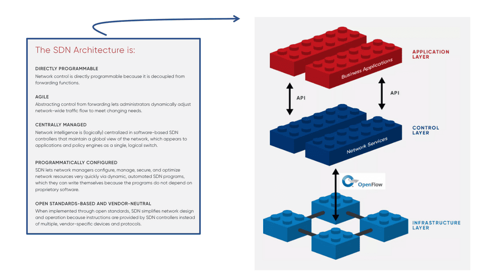
3: OpenFlow has significantly impacted network architecture, prompting a shift towards software-defined networking (SDN). SDN architectures provide a more agile and adaptable network infrastructure, enabling organizations to respond quickly to changing business requirements.
4: With OpenFlow as the backbone, SDN allows for the abstraction of network functions, making networks more programmable, scalable, and cost-effective.
**Key OpenFlow Features**
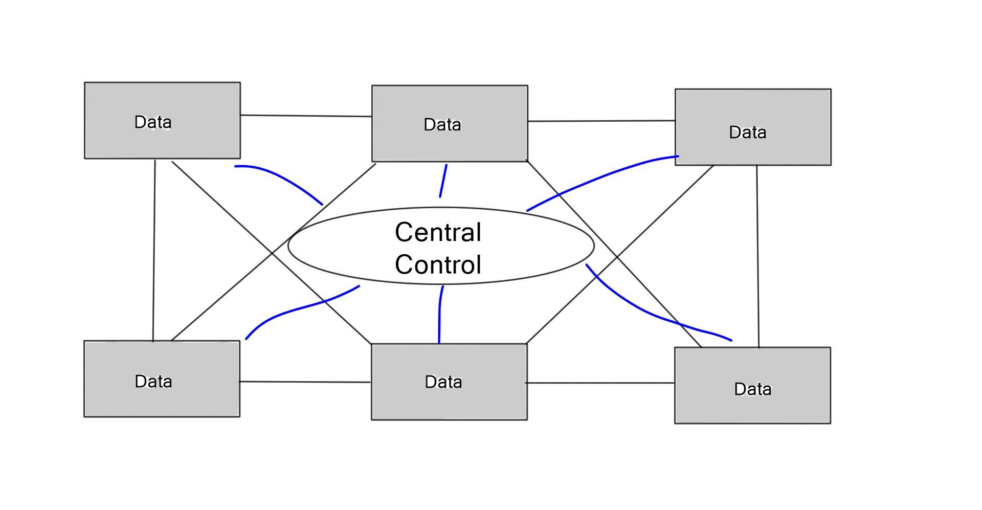
1. Centralized Control: OpenFlow Protocol provides a centralized control mechanism by decoupling the control plane from the devices. This allows network administrators to manage and configure network resources dynamically, making adapting to changing network demands easier.
2. Programmability: OpenFlow Protocol enables network administrators to program the behavior of network devices according to specific requirements. This programmability allows for greater flexibility and customization, making implementing new network policies and services easier.
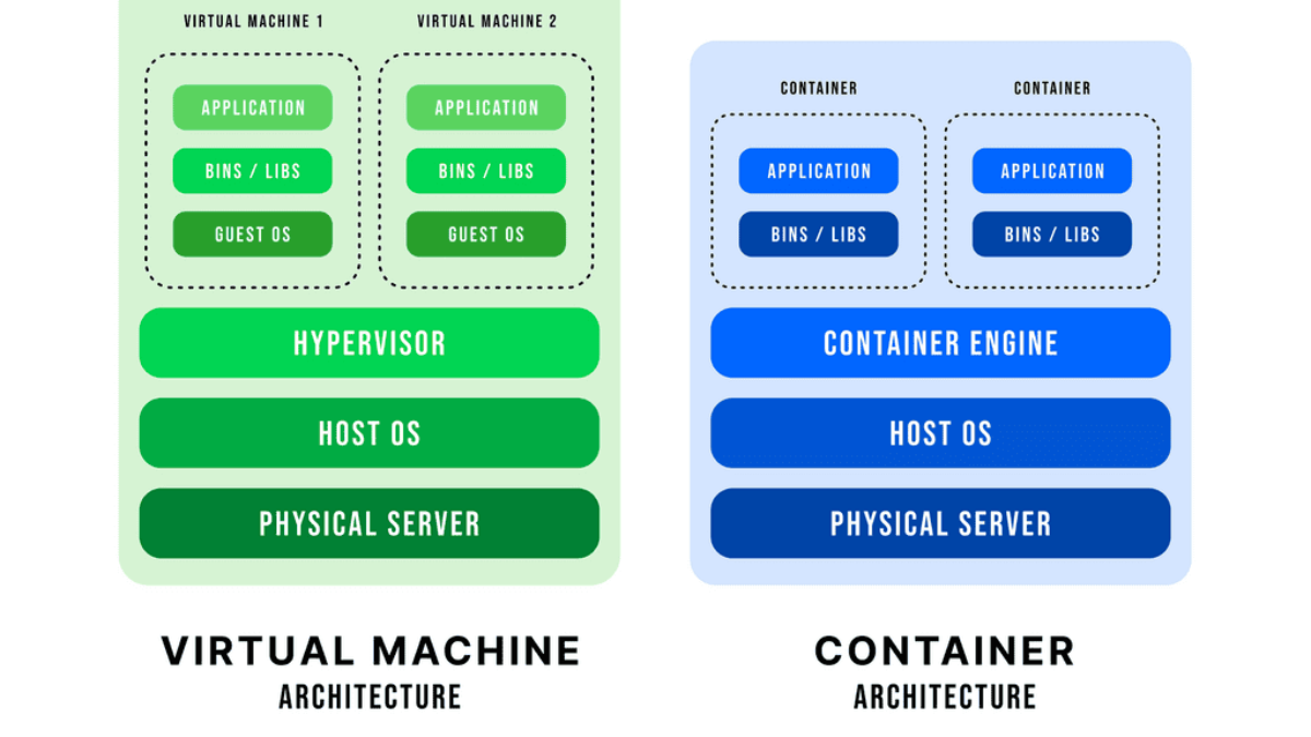
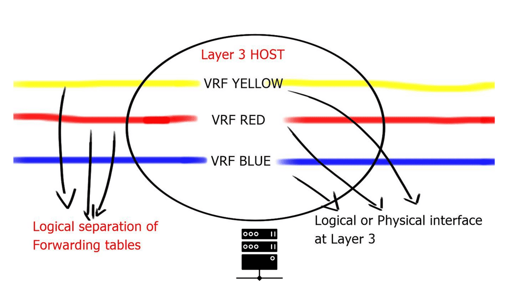
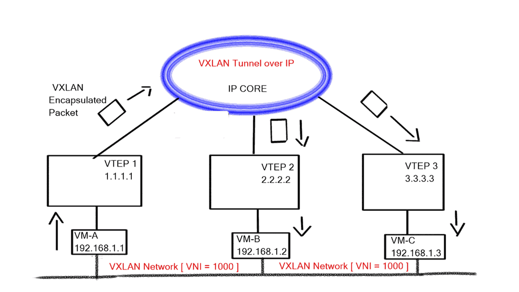
3. Network Virtualization: OpenFlow Protocol supports virtualization, allowing multiple virtual networks to coexist on a single physical infrastructure. This capability enhances resource utilization and enables the creation of isolated network environments, enhancing security and scalability.
4. Traffic Engineering: With OpenFlow Protocol, network administrators have fine-grained control over traffic flows. This enables efficient load balancing, prioritization, and congestion management, ensuring optimal performance and resource utilization.
5. Software-Defined Networking (SDN): OpenFlow is a foundational element of Software-Defined Networking (SDN) architectures. SDN leverages the power of OpenFlow to decouple network control from hardware, enabling dynamic network management, automation, and scalability.
6. Traffic Engineering and Quality of Service (QoS): OpenFlow’s fine-grained control over network traffic enables advanced traffic engineering techniques. Network administrators can then prioritize specific types of traffic, allocate bandwidth efficiently, and ensure optimal Quality of Service (QoS) for critical applications.
**OpenFlow Use Cases**
1. Software-Defined Networking (SDN): OpenFlow Protocol is a key component of SDN, a network architecture separating the control and data planes. SDN leverages OpenFlow Protocol to provide a more flexible, programmable, and scalable network infrastructure.
2. Data Center Networking: OpenFlow Protocol offers significant advantages in data center environments, where dynamic workload placement and resource allocation are crucial. Using OpenFlow-enabled switches and controllers, data center operators can achieve greater agility, scalability, and efficiency.
3. Campus and Enterprise Networks: OpenFlow Protocol can simplify network management in large campus and enterprise environments. It allows network administrators to centrally manage and control network policies, improving network security, traffic engineering, and troubleshooting capabilities.
SDN: A History Guide
Martin Casado, a general partner at Andreessen Horowitz, would handle all the changes in the network industry. Previously, Casado worked for VMware as a fellow, senior vice president, and general manager. In addition to his direct contributions (like OpenFlow and Nicira), he has opened large network incumbents to the need to change network operations, agility, and manageability.
The Software-Defined Networking movement began with OpenFlow, whether for good or bad. During his Ph.D. at Stanford University, Casado worked on OpenFlow under Nick McKeown. Decoupling a network device’s control and data planes from the OpenFlow protocol is possible. A network device’s control plane consists of its brain, while its data plane consists of hardware that forwards packets or application-specific integrated circuits (ASICs).
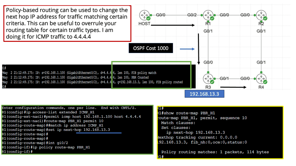
Alternatively, OpenFlow can be run in a hybrid mode. It can be deployed on a specific port, virtual local area network (VLAN), or a regular packet-forwarding pipeline. Since there is no match in the OpenFlow table, packet forwarding is equivalent to policy-based routing (PBR).
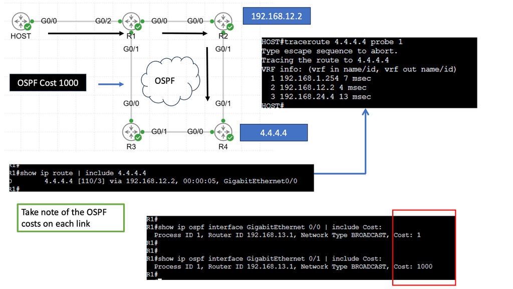
OpenFlow provides granularity in determining forwarding paths (matching fields in packets) because its tables support more than destination addresses. PBR provides granularity by considering the source address when selecting the next routing hop.
In a similar way to OpenFlow, it allows network administrators to forward traffic based on non-traditional attributes, such as packet source addresses. Despite taking quite some time for network vendors to offer comparable performance for PBR-forwarded traffic, the final result was still very vendor-specific.
OpenFlow allowed us to make traffic-forwarding decisions at the same granularity as before but without vendor bias. Thus, network infrastructure capabilities could be enhanced without waiting for the following hardware version.
Example Technology: Policy-Based Routing
**The Mechanics of Policy-Based Routing**
At its core, policy-based routing enables network operators to define custom routes based on a variety of criteria such as source IP address, application type, or even specific user requirements. This flexibility is particularly valuable in scenarios where network administrators need to manage traffic efficiently across multiple paths. By creating and applying access control lists (ACLs), administrators can dictate how and where traffic should flow, optimizing network performance and ensuring compliance with organizational policies.
**Benefits of Implementing PBR**
One of the primary advantages of policy-based routing is its ability to enhance the quality of service (QoS) across a network. By prioritizing certain types of traffic—such as VoIP or video conferencing—PBR can reduce latency and improve overall communication quality. Additionally, PBR can aid in load balancing by distributing traffic evenly across available links, preventing bottlenecks and ensuring that no single path becomes overwhelmed.
**Challenges and Considerations**
While the benefits of PBR are substantial, implementing it is not without challenges. Network administrators must carefully design and test their routing policies to avoid unintended consequences, such as routing loops or security vulnerabilities. Furthermore, the complexity of managing numerous policies can increase administrative overhead. Therefore, it’s crucial for organizations to invest in training and tools that simplify the management of PBR configurations.
Real-World Applications of OpenFlow
So, what is OpenFlow? OpenFlow is an open-source communications protocol that enables remote control of network devices from a centralized controller. It is most commonly used in software-defined networking (SDN) architectures, allowing networks to be configured and managed from a single point. OpenFlow enables network administrators to programmatically control traffic flow across their networks, allowing them to respond quickly to changing traffic patterns and optimize network performance.
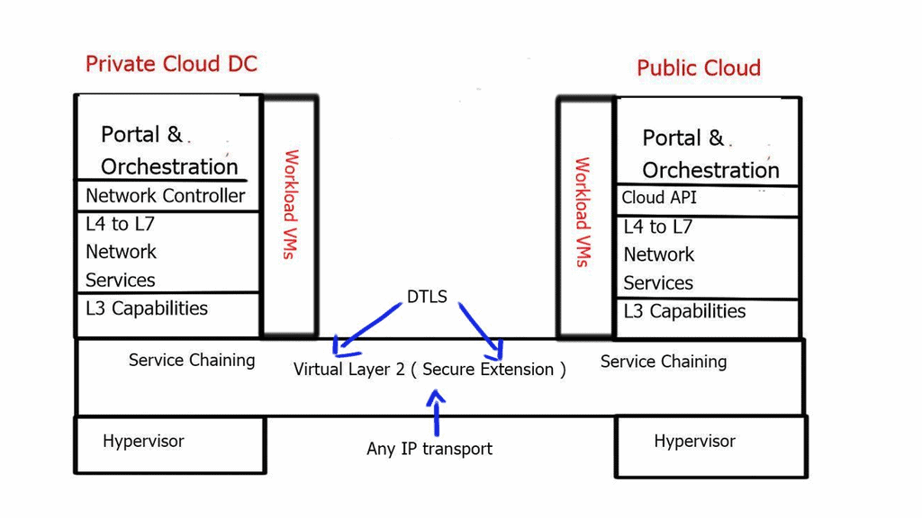
**The Creation of Virtual Networks**
OpenFlow will also help it create virtual networks on top of existing physical networks, allowing for more efficient and flexible network management. As a result, OpenFlow is an essential tool for building and managing modern, agile networks that can quickly and easily adapt to changing network conditions. The following post discusses OpenFlow, the operations of the OpenFlow protocol, and the OpenFlow hardware components you can use to build an OpenFlow network.
You may find the following helpful post for pre-information:
OpenFlow history
OpenFlow started in the labs as an academic experiment. They wanted to test concepts about new protocols and forwarding mechanisms on real hardware but failed with current architectures. The challenges of changing forwarding entries in physical switches limited the project to emulations. Emulations are a type of simulation and can’t mimic an entire production network.
The requirement to test on actual hardware (not emulations) leads to separating device planes (control, data, and management plane) and introducing the OpenFlow protocol and new OpenFlow hardware components.
Highlighting SDN
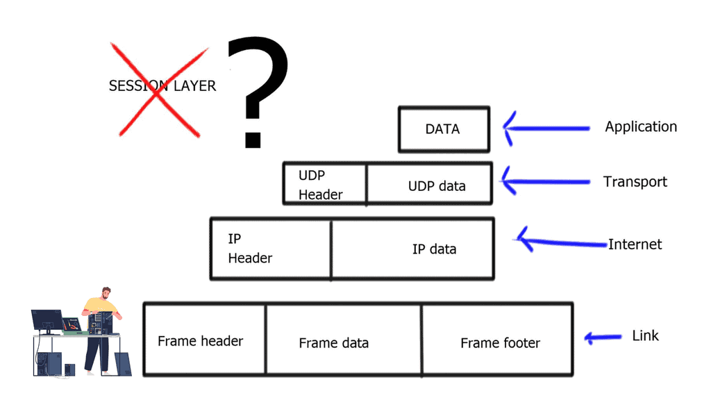
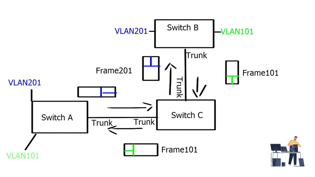
Standard network technologies, consisting of switches, routers, and firewalls, have existed since the inception of networking. Data at each layer is called different things, and forwarding has stayed the same since inception. Frames and packets have been forwarded and routed using a similar approach, resulting in limited efficiency and a high maintenance cost.
Consequently, there was a need to evolve the techniques and improve network operations, which led to the inception of SDN. SDN, often considered a revolutionary new idea in networking, pledges to dramatically simplify network control and management and enable innovation through network programmability.
- A key point: The OpenFlow Protocol versions
OpenFlow has gone through several versions, namely versions 1.0 to 1.4. OpenFlow 1.0 was the initial version of the Open Network Foundation (ONF). Most vendors initially implemented version 1.0, which has many restrictions and scalability concerns. Version 1.0 was limited and proved the ONF rushed to the market without having a complete product.
Not many vendors implemented versions 1.1 or 1.2 and waited for version 1.3, allowing per-flow meter and Provider Backbone Bridging (PBB) support. Everyone thinks OpenFlow is “open,” but it is controlled by a closed group of around 150 member organizations, forming the ONF. The ONF specifies all the OpenFlow standards, and work is hidden until published as a standard.
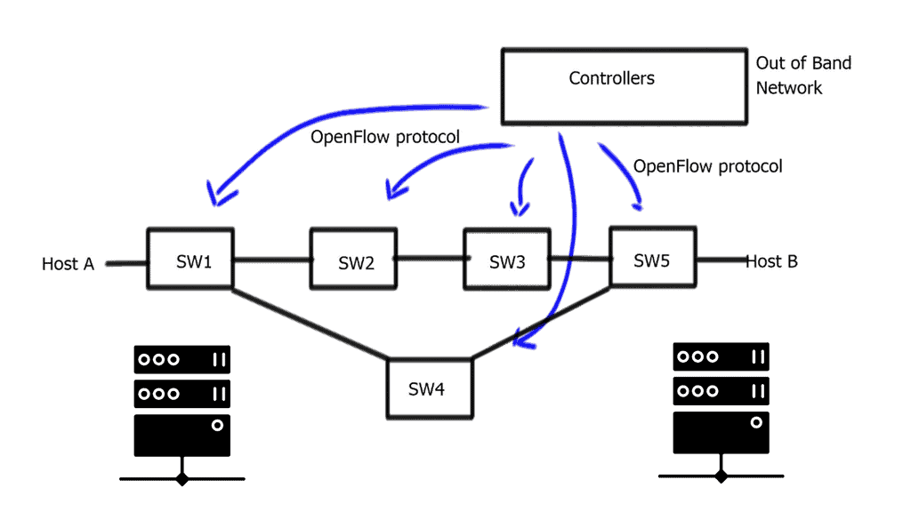
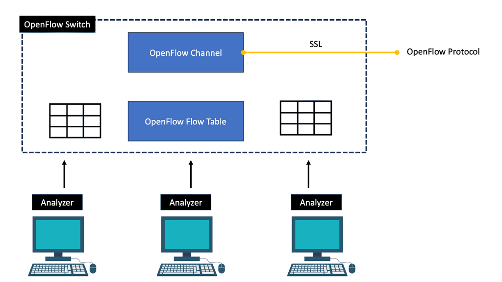
OpenFlow Protocol: Separation of Planes
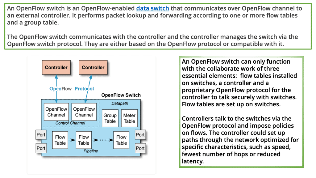
An OpenFlow network has several hardware components that enable three independent pieces: the data plane, control plane, and management plane.
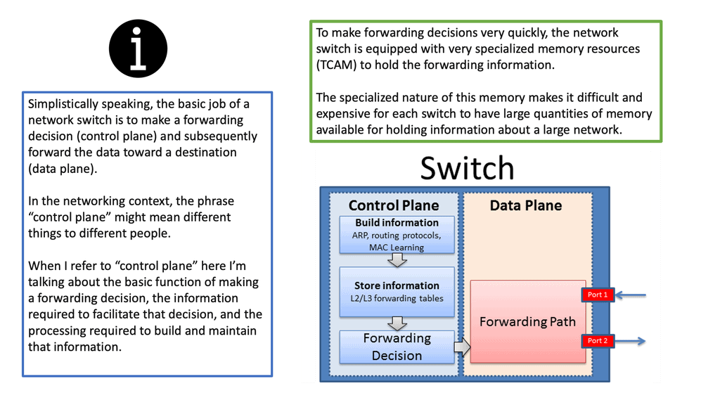
A: – The data plane
The data plane switches Protocol Data Units (PDU) from incoming ports to destination ports. It uses a forwarding table. For example, a Layer 2 forwarding table could list MAC addresses and outgoing ports. A Layer 3 forwarding table contains IP prefixes with next hops and outgoing ports. The data plane is not responsible for creating the controls necessary to forward. Instead, someone else has the job of “filling in” the data plane, which is the control plane’s function.
B: – The control plane
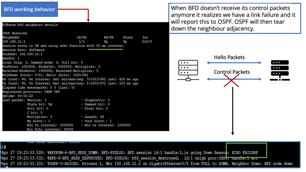
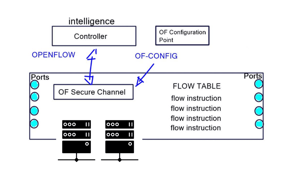
The control plane is responsible for giving the data plane the required information to enable it to forward. It is considered the “intelligence” of the network as it makes the decisions about PDU forwarding. Control plane protocols are not limited to routing protocols; they’re more than just BGP and OSPF. Every single protocol that runs between adjacent devices is usually a control plane. Examples include line card protocols such as BFD, STP, and LACP.
These protocols do not directly interface with the forwarding table; for example, BFD detects failures but doesn’t remove anything from the forwarding table. Instead, it informs other higher-level control plane protocols of the problem and leaves them to change the forwarding behavior.
C: – The management plane
On the other hand, protocols like OSPF and ISIS directly influence the forwarding table. Finally, the management plane provides operational access and monitoring. It permits you or “something else” to configure the device.
**The Idea of OpenFlow Protocol**
OpenFlow is not revolutionary new; similar ideas have been around for the last twenty years. RFC 1925 by R. Callon presents what is known as “The Twelve Network Truths.” Section 2.11 states, “Every old idea will be proposed again with a different name and a different presentation, regardless of whether it works.” Solutions to old problems are easily dressed up in new clothes, but the problems stay the same.
Example: Use case of vendors and OpenFlow hardware.
The scalability of a central control plane will always pose challenges. We had this with the SDH/SONET and Frame Relay days. NEC and Big Switch networks tried to centralize, eventually moving as much as possible to local devices or limiting the dynamic nature and number of supported protocols.
For example, NEC permits only static port channels, and if you opt for Layer 3 IP forwarding, the only control protocol they support is ARP. Juniper implemented a scalable model with MP-BGP, retaining low-level control plane protocols on local switches. Putting all the routine easy jobs on the local switch makes the architecture more scalable.
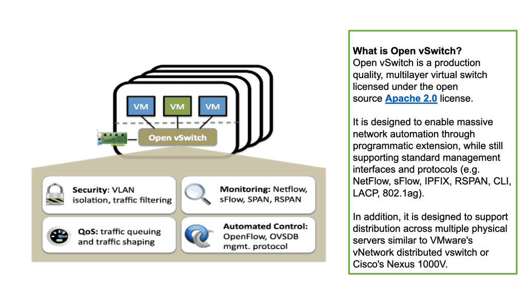
Cisco DFA or ACI uses the same architecture. It’s also hard to do fast feedback looks and fast convergence with a centralized control plane. OpenFlow and centralized control plane-centric SDN architectures do not solve this. You may, however, see OpenFlow combined with the Open vSwitch. Consider the Open vSwitch, also known as OVS, and the OVS bridge as the virtual switch in the data path.
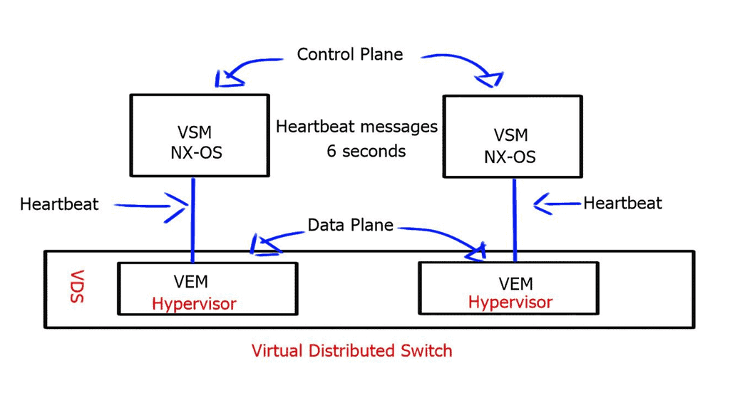
A key point: Open vSwitch
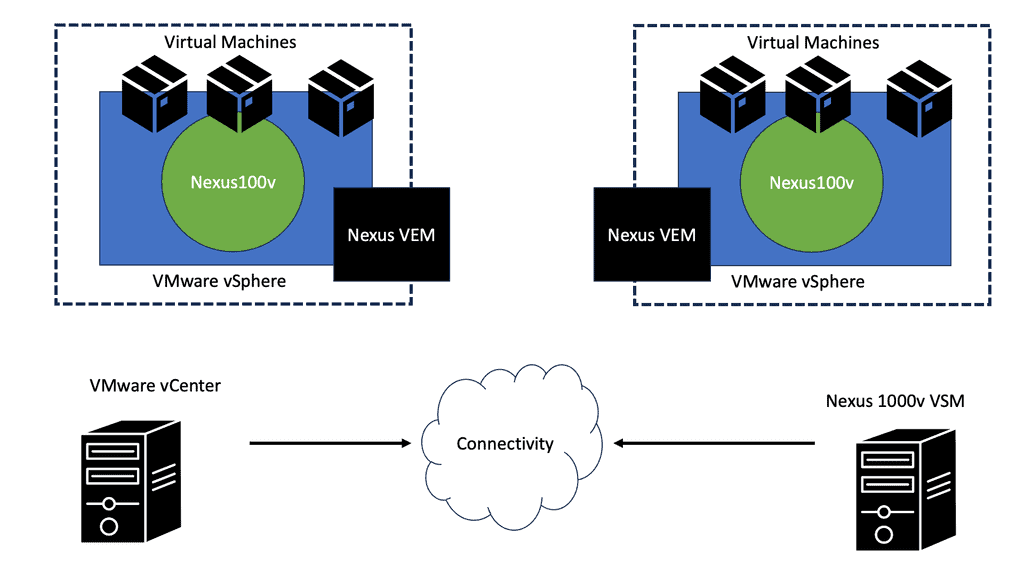
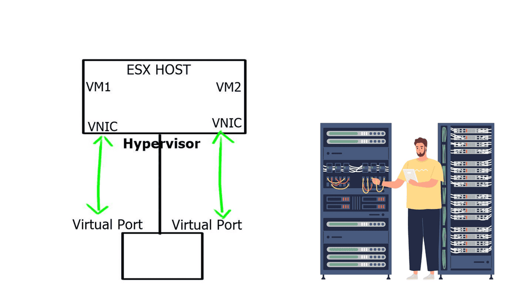
The Open vSwitch is an open-source multi-layered switch that allows hypervisors to virtualize the networking layer. It is designed to enable network automation through programmatic extension. The OVS bridge supports standard management interfaces and protocols such as NetFlow, LACP, and 802.1ag). This caters to many virtual machines running on one or more physical nodes. The virtual machines connect to virtual ports on virtual bridges (inside the virtualized network layer.)
A key point: OpenFlow and Open Networking
Today, with many prominent vendors, we need an open interface to the forwarding plane. Many refer to this as monolithic, closed, and mainframe-like networking devices. On the other hand, a protocol such as OpenFlow. OpenFlow allows direct access to and manipulation of the forwarding plane of the network device. We can now move network control out of proprietary network switches and into open-source and locally managed control software. We were driving a new world of open networking.
OpenFlow protocol and decoupling
The idea of OpenFlow is straightforward. Let’s decouple the control and management plane from the switching hardware. Split the three-plane model where the dumb hardware is in one box, and the brains are in the other. The intelligence has to have a mechanism to push the forwarding entries, which could be MAC, ACL, IP prefix, or NAT rules to the local switches. The protocol used to push these entries is OpenFlow.
OpenFlow is viewed as a protocol with several instruction sets and an architecture. But it is nothing more than a Forwarding ( TCAM ) download protocol. It cannot change the switch hardware functionality. If something is supported in OpenFlow but not in the hardware, OpenFlow cannot do anything for you.
Just because OpenFlow versions allow specific matching doesn’t mean that the hardware can match those fields. For example, Juniper uses OpenFlow 1.3, which permits IPv6 handling, but its hardware does not permit matching on IPv6 addresses.
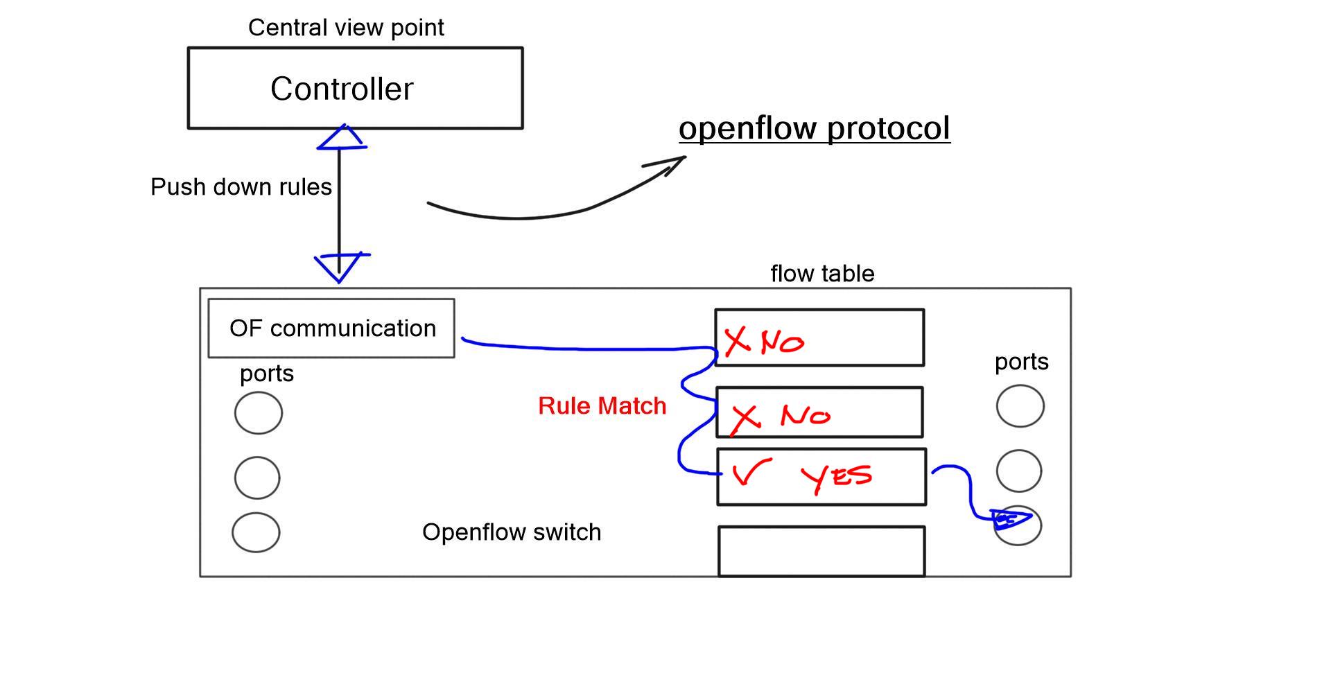
Flow table and OpenFlow forwarding model
The flow table in a switch is not the same as the Forwarding Information Base (FIB). The FIB is a simple set of instructions supporting destination-based switching. The OpenFlow table is slightly more complicated and represents a sequential set of instructions matching multiple fields. It supports flow-based switching.
OpenFlow 1.0 – Single Table Model: OpenFlow hardware with low-cost switches
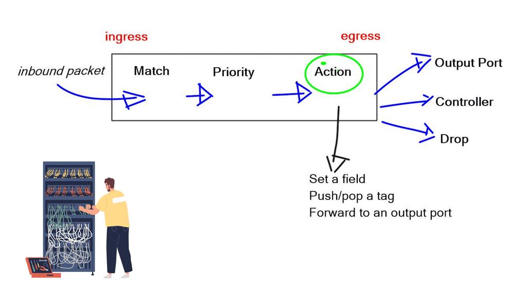
The initial OpenFlow forwarding model was simple. They based the model of OpenFlow on low-cost switches that use TCAM. Most low-cost switches have only one table that serves all of the forwarding needs of that switch. As a result, the model for the OpenFlow forwarding model was a straightforward table. First, a packet is received on an interface; we extract metadata (like incoming interface) and other header fields from the packet.
Then, the fields in the packet are matched in the OpenFlow table. Every entry in a table has a protocol field, and the match with the highest priority is the winner. Every line in the table should have a different priority; the highest-priority match determines the forwarding behavior.
- If you have simple MAC address forwarding, i.e., building a simple bridge. All entries are already distinct. So, there is no overlap, and you don’t need to use the priority field.
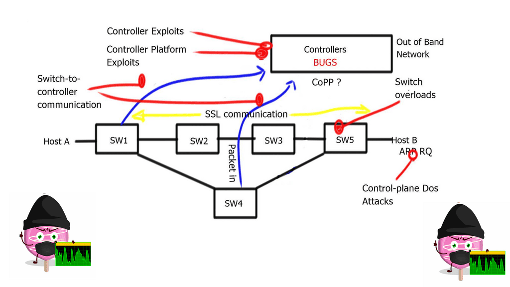
Once there is a match, the packet’s action is carried out. The action could be to send to an interface, drop, or send to the controller. The default behavior of OpenFlow 1.0 would send any unmatched packets to the controller. This punting was later removed as it exposed the controller to DoS attacks. An attacker could figure out what is not in the table and send packets to that destination, completely overloading the controller.
The original OpenFlow specifications could be sent to the interface or the controller. Still, they figured out they may need to modify the packet, such as changing the TTL, setting a field, and pushing/pop tags. They realized version 1.0 was broken, and you must do more than one action on every specific packet. Multiple actions must be associated with each flow entry. This was later addressed in subsequent OpenFlow versions.
OpenFlow ports
OpenFlow has the concept of ports. Ports on an OpenFlow switch serve the same input/output purposes as any switch. From the perspective of ingress and egress traffic flows, it is no different from any other switch. For example, the ingress port for one flow might be the output port for another flow.
OpenFlow defines several standard ports, such as physical, logical, and reserved. Physical ports correspond directly to the hardware. Logical ports do not directly correspond to hardware, such as MPLS LSP, tunnel, and null interfaces.
Reserved ports are used for internal packet processing and OpenFlow hybrid switch deployments. Reserved ports are either required or optional. Required ports include ALL, CONTROLLER, TABLE, IN_PORT, and ANY. In comparison, the Optional ports include LOCAL, NORMAL, and FLOOD.
TCAM download protocol
OpenFlow is simply a TCAM download protocol. OpenFlow cannot do this if you want to create a tunnel between two endpoints. It does not create interfaces for you. Other protocols, such as OF-CONFIG, use NETCONF for this job. It is a YANG-based data model. OpenFlow protocol is used between the controller and the switch, while OF-CONFIG is used between a configuration point and the switch. A port can be added, changed, or removed in the switch configuration with OF-CONFIG, not OpenFlow.
Port changes (state) do not automatically change the direction of the flow entry. For example, a flow entry will still point to that interface if a port goes down and subsequent packets are dropped. All port changes must first be communicated to the controller so it can make changes to the necessary forwarding by downloading instructions with OpenFlow to the switches.
A variety of OpenFlow messages are used for switch-to-controller and controller-to-switch communication. We will address these in the OpenFlow Series 2 post.
OpenFlow Classifiers
OpenFlow is modeled like a TCAM, supporting several matching mechanisms. You can use any combination of packet header fields to match a packet. Possibilities to match on MAC address (OF 1.0), with wildcards (OF 1.1), VLAN and MPLS tag (OF 1.1), PBB headers (OF 1.3), IPv4 address with wild cards, ARP fields, DSCP bits. Not many vendors implement ARP field matching due to hardware restrictions. Much current hardware does not let you look deep into ARP fields. IPv6 address (OF 1.2) and IPv6 extension headers (OF1.3), Layer 4 protocol, TCP, and UDP port numbers are also supported.
Once a specific flow entry matches a packet, you can specify the number of actions. Options include output to the port type: NORMAL port for traditional processing, LOCAL PORT for the local control plane, and CONTROLLER port for sending to the controller.
In addition, you may set the OUTPUT QUEUE ID, PUSH/POP VLAN, MPLS, or PBB tags. You can even do a header rewrite, which means OpenFlow can be used to implement NAT. However, be careful with this, as you only have a limited number of flow entries on the switches. Finally, some actions might be in software, which is too slow.
OpenFlow Groups
Finally, there is an exciting mechanism where a packet can be processed through what is known as a GROUP. With OpenFlow 1.1+, the OpenFlow forwarding model included the functionality of GROUPS. Groups enhance the previous OpenFlow forwarding model. However, enhanced forwarding mechanisms like ECMP Load Balancing cannot be completed in OpenFlow 1.0. For this reason, the ONF implemented OUTPUT GROUPS.
A Group is a set of buckets, and a Bucket is a set of actions. For example, an action could be output to port, set VLAN tag, or push/pop MPLS tag. Groups can contain several buckets; bucket 1 could be sent to port 1, and bucket 2 to port 2, but it could also add a tag.
This adds granularity to OpenFlow forwarding and enables additional forwarding methods. For example, sending to all buckets in a group could be used for selective multicast, or sending to one bucket in a group could be used for load balancing across LAG or ECMP.
Final Points: OpenFlow Protocol
OpenFlow Protocol represents a significant advancement in network management, offering a more flexible, programmable, and efficient approach. Decoupling the control and forwarding plane enables centralized control, programmability, and network virtualization. With its wide range of benefits and use cases, OpenFlow Protocol is poised to revolutionize network management and pave the way for future innovations in networking technologies.
As organizations face ever-increasing network challenges, embracing OpenFlow Protocol can provide a competitive edge and drive efficiency in network operations.