data center design

Open Networking

ENGINEERING GUIDE · OPEN NETWORKING

Open Networking — From Disaggregated Hardware to Programmable Fabrics

Open networking is not a single product or protocol. It is an architectural approach that separates hardware, network software, control, telemetry and automation so infrastructure can become more programmable, interoperable and adaptable.

The important engineering shift is not simply replacing a proprietary platform. It is separating the components of the network so that hardware, software, control and operations can evolve independently.
01 · DISAGGREGATE

Separate Hardware

Treat switching hardware and network software as independently selectable components.

02 · PROGRAM

Expose Control

Use protocols, APIs and software interfaces to make network behaviour programmable.

03 · AUTOMATE

Operate at Fabric Scale

Move from box-by-box configuration toward repeatable desired-state workflows.

04 · OBSERVE

Measure Network State

Use telemetry and analytics to understand actual network behaviour continuously.

ENGINEERING MODEL
HARDWARE → NETWORK OS → CONTROL → AUTOMATION → TELEMETRY → ANALYTICS
ENGINEERING QUESTION

Can the network change without requiring every layer to be redesigned or every device to be configured independently?

Open networking moves intelligence toward software, automation and common interfaces.
White-Box Networking Open NOS SONiC FRRouting BGP EVPN VXLAN Leaf-Spine OpenConfig gNMI Automation Telemetry
Interactive Open Networking Architecture

Open Networking Architecture Explorer

Explore how open networking separates hardware, network software, control, telemetry and automation to create a more flexible, programmable and vendor-neutral infrastructure.
From hardware dependency to programmable fabric
Hardware
→
Network Software
→
Control
→
Operations
Disaggregation creates independence
DATA PLANE Forward packets
CONTROL PLANE Build routing state
MANAGEMENT Automate & observe
HW
White-Box Hardware
Disaggregated infrastructure

Open networking separates the physical switching platform from the software controlling it, allowing organizations greater freedom in hardware selection.

Layer Data plane
Principle Hardware / software separation
Benefit Vendor flexibility
Result Reduced lock-in
OPEN NETWORKING PRINCIPLE
Hardware becomes a replaceable platform rather than the sole source of network intelligence.

Why disaggregation matters

Traditional networking commonly couples hardware, operating system and features into a single vendor stack. Open networking separates these functions so each layer can evolve independently.

OPEN STANDARDS Common protocols and models allow different components to interoperate.
OPEN SOFTWARE Network operating systems and routing software can evolve independently of hardware.
OPEN APIs Automation systems can program and integrate the network.
OPEN TELEMETRY Network state becomes observable through streaming data and common models.
Open Networking · Interactive Use Case
How the Open Fabric Works
See how a modern leaf-spine fabric separates the routed underlay from the VXLAN overlay while BGP and EVPN provide the control plane.
L3 UNDERLAY
VXLAN OVERLAY
WORKLOADS
BGP EVPN CONTROL PLANE
VNI 10100 · VXLAN SEGMENT
SPINE 1
S1
Transit
SPINE 2
S2
Transit
LEAF 1
L1
VTEP
LEAF 2
L2
VTEP
VM-A
Host A
10.10.1.10
VM-B
Host B
10.10.1.20
VM-C
Host C
10.10.1.30
Open Fabric
Click a device to explore its role in the open fabric.
Underlay
IP + BGP
Control Plane
BGP EVPN
Overlay
VXLAN VNI 10100
Architecture
Leaf / Spine
BGP Underlay Routed IP connectivity between leaf and spine switches.
EVPN Control Plane BGP distributes MAC/IP and endpoint reachability information.
VXLAN Overlay VXLAN carries logical network segments across the IP fabric.
VTEP Leaf switches encapsulate and decapsulate VXLAN traffic.
01 · DEFINE · ARCHITECTURE

What Does “Open” Actually Mean?

Open networking begins by separating the components that traditionally arrive as one integrated platform: hardware, network operating system, control protocols and operational tooling. The engineering objective is reduced coupling, greater choice and programmable interfaces.

Engineering Question Can each layer evolve without forcing the entire network architecture to change with it?
01 · DEFINE · OPEN NETWORKING ARCHITECTURE

Open Networking Starts With Separation

Open networking begins by separating the functions that traditional networking often bundles together. Hardware provides forwarding capability, network software provides operating and routing functions, control protocols build network state, and automation and telemetry provide the operational feedback loop.

ARCHITECTURAL LAYERS
HARDWARE Switching silicon, ports, memory and physical forwarding resources.
NETWORK OS Operating system, routing software, interfaces and platform services.
CONTROL BGP, OSPF, IS-IS, EVPN and other mechanisms that establish network state.
OPERATIONS APIs, automation, configuration management, telemetry and analytics.
OPEN NETWORKING PRINCIPLES
Hardware Independence

Hardware can become a replaceable platform rather than defining the entire software stack.

Software Choice

Network operating systems and routing software can be selected according to operational requirements.

Open Interfaces

Standards, APIs and models allow systems to exchange state and participate in common workflows.

Operational Automation

Configuration and lifecycle operations can move from individual devices toward repeatable fabric-wide processes.

ENGINEERING PRINCIPLE

Open networking is not simply “using open source.” The architectural objective is to reduce unnecessary coupling between hardware, software, control and operations so that each layer can evolve without forcing the entire network to change with it.

DATA PLANE
Forward the packet

The forwarding infrastructure moves traffic according to the state programmed into the network.

CONTROL PLANE
Build network state

Routing protocols and control systems determine reachability and distribute network information.

MANAGEMENT PLANE
Operate the fabric

APIs, automation and telemetry provide the mechanisms for configuring, observing and validating the network.

02 · DISAGGREGATE · PLATFORM

Separate the Platform From the Network Software

Disaggregation separates the physical switching platform from the network software that controls it. White-box hardware, open network operating systems and routing software can therefore become independent architectural choices rather than a single fixed product.

Engineering Question Which parts of the network platform actually need to come from the same supplier?
ENGINEERING LAB · 01 · DEFINE

Open Networking Architecture Explorer

Explore the four architectural layers that turn a traditional integrated network platform into a more modular and programmable system. Select a layer or use the architecture tabs to inspect what becomes separated and why that separation matters.

OPEN NETWORKING STACK
● MODULAR
LAYER INSPECTOR
SELECTED
01 · PLATFORM

Hardware

Open networking separates the physical switching platform from the software that operates it. This creates greater freedom in choosing the underlying hardware platform, but also introduces responsibility for validating compatibility and lifecycle support.

Network software
Platform choice
Integration & support
White-box switching
OPENNESS SIGNAL

The hardware platform no longer has to dictate which network software is used.

02 · DISAGGREGATE · HARDWARE, NOS & CONTROL PLANE

Separate the Platform From the Network Software

Disaggregation separates the physical switching platform from the network operating system and the control protocols running above it. This creates greater architectural choice, but it also makes lifecycle, integration, compatibility and operational ownership more important.

THE DISAGGREGATED STACK
WHITE-BOX HARDWARE Switching ASICs, interfaces, buffers and physical resources. The platform provides forwarding capability without necessarily defining the complete software stack.
NETWORK OS Software responsible for operating the device, exposing interfaces and integrating routing and forwarding functions.
ROUTING SOFTWARE Protocol implementations such as BGP, OSPF or IS-IS build control-plane state and calculate reachability.
MANAGEMENT APIs, configuration models and automation systems provide the operational interface to the device or fabric.
CONTROL-PLANE EXAMPLES
BGP

Exchanges reachability information between routing peers and is widely used for data-centre and service-provider fabrics.

OSPF

Link-state routing protocol commonly used to build internal IP reachability within an autonomous system.

IS-IS

Link-state protocol used extensively in large-scale provider and data-centre network designs.

EVPN

A BGP-based control-plane technology commonly used to distribute MAC and IP reachability information for modern overlays.

01 · HARDWARE
Forwarding Resources

ASICs and interfaces determine what the platform can physically forward at line rate.

02 · NOS
Operating Environment

The network OS provides the software environment that connects the platform to routing and operational functions.

03 · CONTROL
Network Intelligence

Routing protocols exchange information and construct the state used to make forwarding decisions.

04 · OPERATE
Automation Interface

APIs, models and automation turn individual device configuration into repeatable operational workflows.

ENGINEERING REALITY

Disaggregation increases choice, but choice introduces responsibility. Hardware compatibility, NOS support, routing features, lifecycle management, observability and operational skills must all be considered as part of the architecture.

ENGINEERING LAB · 02 · DISAGGREGATE

Disaggregation Decision Lab

Build an open networking platform by selecting the hardware, network operating system and control model. The objective is not simply to choose “open” components — it is to understand the engineering trade-offs created when the layers are separated.

PLATFORM BUILDER
MODULARITY 82%
01 · Hardware Choose platform
02 · Network OS Choose software
03 · Control Choose model
ARCHITECTURE RESULT
CONFIGURATION READY
Selected Architecture
Hardware White-Box Switching Platform
Network Operating System Open Network OS
Control Open Standards & APIs
Operations Automation + Telemetry
Engineering Assessment
Platform choice
88
Software freedom
86
Integration effort
42
Vendor coupling
24
High platform and software choice
More integration responsibility
ENGINEERING DECISION

Disaggregation increases architectural choice, but the responsibility for validating hardware, software, interoperability and lifecycle support also increases.

03 · FABRIC · BGP EVPN

Build the Fabric With a Routed Underlay

Once the hardware and software layers are separated, the network can be designed as a programmable fabric. A routed IP underlay provides predictable transport while BGP EVPN and VXLAN can provide the control and overlay mechanisms required for scalable workload connectivity.

Engineering Question Can the physical fabric remain simple while the overlay provides the required logical connectivity?
03 · FABRIC · LEAF-SPINE & BGP EVPN

Build the Fabric With a Routed Underlay and Programmable Overlay

Open networking becomes especially powerful when disaggregated components are assembled into a fabric. A routed leaf-spine underlay provides predictable IP connectivity, while BGP and EVPN can distribute the control-plane information required for scalable workload and overlay connectivity.

FABRIC ARCHITECTURE
SPINE
High-speed routed transit between leaf switches. The spine provides fabric connectivity rather than directly hosting workloads.
LEAF
Connects servers, appliances and external networks while providing the edge of the fabric.
UNDERLAY
Routed IP transport between fabric devices. BGP, OSPF or IS-IS can provide the reachability required by the design.
OVERLAY
VXLAN can provide virtual network segmentation while EVPN distributes endpoint reachability through the control plane.
SERVER
→
LEAF
→
SPINE
→
LEAF
→
SERVER
CONTROL-PLANE MODEL
IP UNDERLAY

Provides simple routed reachability between the devices that make up the fabric.

BGP

Can provide scalable routing between leaf and spine devices and establish the fabric's IP reachability.

EVPN

Uses BGP to distribute MAC and IP reachability information for modern Ethernet VPN designs.

VXLAN

Encapsulates tenant traffic across the IP underlay and identifies virtual networks using a VNI.

01 · UNDERLAY
Transport Layer

The underlay answers a fundamental question: can the fabric devices reach one another reliably?

02 · CONTROL
Reachability State

Routing protocols exchange information so devices can calculate paths through the fabric.

03 · OVERLAY
Virtual Networks

VXLAN separates logical networks from the physical topology and provides scalable segmentation.

04 · EVPN
Endpoint Knowledge

EVPN distributes endpoint reachability through the control plane, reducing reliance on traditional flood-and-learn behaviour.

ENGINEERING PRINCIPLE

Keep the underlay simple and predictable. Put the complexity required for tenant connectivity, segmentation and endpoint distribution into the overlay and its control plane. This separation makes the fabric easier to reason about, troubleshoot and automate.

ENGINEERING LAB · 03 · FABRIC

Open Fabric Path Lab

Follow a packet through a modern open networking fabric. Select each stage to expose the engineering evidence behind the underlay, BGP control plane, EVPN and VXLAN overlay.

Stage 1 of 6
Fabric Path
Host A → Host B
Packet context: Host A · 10.10.10.21 → Host B · 10.10.20.31 · VNI 10100
Underlay
Keep Transport Simple
The routed fabric provides IP reachability between loopbacks and VTEPs. The underlay should not need to understand tenant networks.
Overlay
Move Tenant State Into EVPN
EVPN distributes endpoint and MAC/IP reachability information through the control plane rather than relying only on data-plane flooding.
Live Trace
Path Evidence
00:00 Path investigation initialised
00:01 Ingress leaf selected
04 · PROGRAM · AUTOMATION

Turn Network Operations Into a Programmable System

Open interfaces become valuable when they can be used consistently by automation. Models such as OpenConfig, interfaces such as gNMI, and tools such as Ansible and Terraform allow network intent to become repeatable change rather than a sequence of manual device commands.

Engineering Question Can the same intended network state be deployed repeatedly and then verified automatically?
04 · PROGRAM · APIs, AUTOMATION & DESIRED STATE

Turn Network Operations Into a Programmable System

Once hardware and network software are separated, the next engineering challenge is operating the infrastructure consistently. APIs, configuration models and automation allow engineers to describe, deploy and validate network state without relying on repetitive device-by-device configuration.

FROM INTENT TO NETWORK STATE
01
INTENT

Define what the network should provide.

02
MODEL

Represent configuration using structured data and models.

03
AUTOMATE

Apply repeatable changes across the infrastructure.

04
DEPLOY

Push validated state into network devices and services.

05
VERIFY

Compare the resulting state with the intended state.

06
REPEAT

Treat network change as an operational lifecycle.

OPEN PROGRAMMABILITY TOOLBOX
OpenConfig

Open, vendor-neutral data models commonly used to represent network configuration and operational state.

gNMI

A management interface commonly used to retrieve and modify structured configuration and operational data.

Ansible

Automation and configuration-management tooling suited to repeatable network changes and operational workflows.

Terraform

Infrastructure-as-code tooling commonly used to provision and manage infrastructure through declarative configuration.

DAY 0 → DAY 1 → DAY 2
DAY 0 · BOOTSTRAP Establish the initial platform, management connectivity, credentials and baseline configuration.
DAY 1 · DEPLOY Introduce production services such as routing, VLANs, VRFs, interfaces and fabric configuration.
DAY 2 · OPERATE Continue monitoring, changing, validating and remediating the network throughout its lifecycle.
ENGINEERING PRINCIPLE

Automation should not simply make configuration faster. The stronger objective is repeatability: the same intent should produce a predictable result, and the resulting network state should be measurable and verifiable.

API
Expose the Network

APIs provide a programmable interface instead of forcing every operation through manual CLI interaction.

MODEL
Structure the State

Models provide a consistent representation of configuration and operational information.

AUTOMATION
Scale the Change

Automation turns individual operations into repeatable workflows that can be applied across the fabric.

ENGINEERING LAB · 04 · PROGRAM

Desired-State Automation Lab

Define the network you want, generate the intended configuration, deploy the change, then verify that the fabric actually reached the desired state.

Intent not deployed
Define Intent
Desired state
Fabric Protocol
Overlay
Automation
Validation
Automation Pipeline
Awaiting plan
01
Intent
Defined
02
Model
Pending
03
Deploy
Pending
04
Observe
Pending
05
Verify
Pending
Generated Plan
Configuration Intent
# intent fabric.protocol = BGP overlay = EVPN/VXLAN automation = model-driven validation = telemetry
Configuration Diff
Proposed Change
+ enable bgp fabric + enable evpn overlay + configure telemetry
PENDING
Config State
PENDING
Control Plane
PENDING
Data Plane
PENDING
Telemetry
05 · OBSERVE · TELEMETRY

You Cannot Automate What You Cannot Observe

Programmable infrastructure needs equally strong visibility. Interface state, routing information, traffic flows and system health provide the evidence required to understand what the network is actually doing. Telemetry turns network state into operational data.

Engineering Question Can the network prove what changed, what is happening now and whether the resulting state is healthy?
05 · OBSERVE · TELEMETRY & NETWORK VISIBILITY

Expose the State of the Network

Programmability is only useful when engineers can also observe the resulting network state. Open networking therefore depends on telemetry that exposes interfaces, routing state, traffic behaviour and system health so that automation can be validated against what the network is actually doing.

NETWORK TELEMETRY SIGNALS
INTERFACES

Counters, errors, link state and utilisation reveal the health of physical and logical interfaces.

ROUTING STATE

BGP, OSPF, IS-IS and EVPN state shows whether the control plane is building the expected reachability.

TRAFFIC FLOWS

Flow records and sampled telemetry provide visibility into communication patterns and traffic volumes.

SYSTEM HEALTH

CPU, memory, buffers, process state and platform health provide additional operational context.

OBSERVABILITY PIPELINE
NETWORK STATE Devices generate operational and protocol information.
TELEMETRY State is exposed through streaming telemetry, APIs or sampled visibility mechanisms.
COLLECT Data is transported into monitoring, analytics or observability systems.
CORRELATE Signals are combined to understand relationships and anomalies.
ACT Engineers or automation can investigate, validate and respond.
STREAMING TELEMETRY
Continuous State

Streaming telemetry can deliver operational state continuously rather than relying entirely on periodic polling.

OPEN MODELS
Structured Data

OpenConfig and interfaces such as gNMI help expose structured configuration and operational information.

FLOW VISIBILITY
Traffic Behaviour

Technologies such as sFlow provide sampled visibility into traffic patterns without requiring full packet capture.

ENGINEERING PRINCIPLE

Automation without telemetry creates blind change. Telemetry without automation creates visibility without scale. The stronger architecture connects both: change the network, observe the result, compare it with the intended state, and investigate any deviation.

ENGINEERING LAB · 05 · OBSERVE

Telemetry Investigation Console

Select the signals you would use to investigate a fabric event, correlate them against the timeline, and build enough evidence to distinguish a control-plane problem from a forwarding or workload problem.

Select evidence
Telemetry Signals
Select multiple
Correlation View
No correlation yet
Signals Selected
0 / 5
Evidence Quality
LOW
Likely Domain
UNKNOWN
Confidence
0%
10:42:01 Baseline stable Leaf and spine interfaces operating normally.
10:42:17 EVPN state changed Remote endpoint reachability changed on Leaf-02.
10:42:18 Traffic drop observed Flow telemetry reports loss toward remote workload.
10:42:21 Interface remains up No physical link failure detected.
10:42:24 System health normal No resource saturation detected.
Investigation Finding
0 evidence sources
Select telemetry sources, then correlate them with the event timeline. The objective is to identify which layer changed first.
06 · OVERLAY · VXLAN

Separate Logical Networks From the Physical Fabric

Modern fabrics often carry many logical networks across the same physical infrastructure. VXLAN provides the encapsulation mechanism, while EVPN can provide the control-plane information required to distribute endpoint and reachability state across the fabric.

Engineering Question Can multiple logical networks share the same physical fabric without coupling tenant connectivity to the physical topology?
06 · OVERLAY · VXLAN & NETWORK VIRTUALISATION

Separate Logical Networks From the Physical Fabric

Network virtualisation allows logical connectivity to span a physical fabric without requiring every physical link to represent a separate tenant or broadcast domain. VXLAN provides the encapsulation mechanism, while EVPN can provide the control-plane information needed to discover and distribute endpoint reachability.

UNDERLAY → OVERLAY MODEL
PHYSICAL FABRIC

Switches, links and interfaces provide the physical transport between fabric nodes.

IP UNDERLAY

Routed connectivity provides the transport path between VTEPs across the fabric.

VXLAN OVERLAY

Tenant Ethernet frames can be encapsulated inside IP packets for transport across the underlay.

EVPN CONTROL PLANE

BGP EVPN distributes endpoint information so VTEPs can make informed forwarding decisions.

VTEP A Workload / VLAN
VNI 10100
VTEP B Workload / VLAN
CONTROL VS DATA PLANE
FUNCTION ROLE
UNDERLAY Provides IP reachability between the physical fabric devices.
VTEP Encapsulates and decapsulates VXLAN traffic at the edge of the overlay.
VNI Identifies a VXLAN virtual network and separates logical connectivity within the overlay.
EVPN Distributes MAC and IP reachability information through the control plane.
VXLAN Carries the overlay traffic across the IP underlay using encapsulation.
01 · VNI
Logical Identifier

VXLAN uses a 24-bit VNI, providing a large identifier space for logical networks.

02 · VTEP
Overlay Edge

VTEPs connect local workloads to the VXLAN overlay and perform encapsulation and decapsulation.

03 · EVPN
Reachability

EVPN provides control-plane distribution of endpoint information rather than relying entirely on flood-and-learn behaviour.

04 · MOBILITY
Physical Independence

Logical networks can span different physical locations and paths without changing the underlying fabric topology.

ENGINEERING PRINCIPLE

The underlay should answer “How do I reach the VTEP?” while the overlay answers “Which logical network and endpoint am I trying to reach?” Keeping those responsibilities separate makes large fabrics easier to scale, troubleshoot and automate.

ENGINEERING LAB · 06 · OVERLAY

VXLAN Overlay Packet Trace

Trace an Ethernet frame across a shared IP fabric and see where the logical network, VNI, VTEPs and VXLAN encapsulation fit into the forwarding path.

Ready to trace
Overlay Parameters
Packet context
H
Host A
10.10.10.21
Ethernet frame
V
VTEP A
Leaf-01
Encapsulation
I
IP Fabric
Underlay
ECMP
V
VTEP B
Leaf-02
Decapsulation
H
Host B
10.10.20.31
Ethernet frame
Current Packet Representation
ETH SRC=H-A DST=H-B
VNI
Logical Network Identity
The VNI identifies the logical VXLAN segment carried across the shared physical fabric. Different VNIs can use the same underlay.
VTEP
Where Encapsulation Happens
The VTEP sits at the edge of the overlay. It encapsulates traffic entering VXLAN and decapsulates traffic leaving the overlay.
Underlay
Transport Does Not Need Tenant State
The IP fabric forwards toward the remote VTEP. The physical transport can remain largely independent from the logical tenant network.
07 · OPERATE · WORKLOAD NETWORKING

Extend Open Networking Into the Host

The network does not end at the top-of-rack switch. Linux networking, virtual switching and container networking extend connectivity into servers and workloads. This creates another programmable layer that must be automated, observed and secured alongside the physical fabric.

Engineering Question Where does the network boundary actually end when applications run inside virtualised or containerised workloads?
07 · OPERATE · LINUX, VIRTUAL SWITCHING & CONTAINERS

Extend Open Networking Into the Workload Layer

Open networking does not stop at the physical switch. Linux networking, virtual switches and container networking extend the same programmable principles into the systems and workloads connected to the fabric. The result is a network model that spans physical interfaces, virtual interfaces, workloads and applications.

SOFTWARE NETWORKING STACK
PHYSICAL NIC Provides host connectivity into the physical network and participates in the server's forwarding path.
LINUX NETWORKING Interfaces, routing, namespaces, bridges, filtering and other kernel networking functions provide the host network layer.
VIRTUAL SWITCH Software such as Open vSwitch can provide programmable switching between physical interfaces, virtual interfaces and workloads.
WORKLOAD NETWORK Containers and virtual workloads consume the networking services provided by the host and its virtual switching layer.
OPEN SOFTWARE COMPONENTS
Linux Networking

Provides interfaces, routing, namespaces, bridges, firewalling and other host-level networking capabilities.

Open vSwitch

A software switch designed for programmable virtual networking and integration with physical and virtual infrastructure.

Network Namespaces

Provide isolated network views that can separate interfaces, routing tables and network resources.

Container Networking

Connects containers to host and external networks through bridges, virtual interfaces or additional networking systems.

01
PHYSICAL

Server connects to the fabric.

02
HOST

Linux provides the local network stack.

03
VIRTUAL

Software switching connects logical interfaces.

04
WORKLOAD

Containers or VMs consume network connectivity.

05
FABRIC

Traffic exits through the physical network.

LINUX
Programmable Host

Linux provides a powerful networking environment that can be automated alongside the physical fabric.

OPEN VSWITCH
Virtual Forwarding

OVS provides software-based switching between virtual and physical network interfaces.

CONTAINERS
Workload Connectivity

Containers consume network connectivity through host and container networking mechanisms rather than directly owning the physical fabric.

ENGINEERING PRINCIPLE

The physical fabric and workload network should be treated as connected layers rather than one giant control plane. The fabric provides transport, while Linux, virtual switching and workload networking provide connectivity closer to the application.

ENGINEERING LAB · 07 · OPERATE

Host Networking Stack Inspector

Follow connectivity from an application workload through the Linux network namespace, virtual switch, physical NIC and finally into the upstream fabric.

Select a host layer
Host Networking Path
Click any layer
Compute Host · worker-07
Linux
External Network Fabric
BGP / EVPN
HOST VTEP 192.0.2.11
↔
FABRIC Leaf / Spine
Linux
Host Networking Is Its Own Layer
Interfaces, namespaces, routing tables and policy exist below the application but above the physical fabric.
Virtual Switching
Forwarding Can Move Into Software
Open vSwitch and other virtual switching mechanisms connect workload interfaces to host uplinks and can apply forwarding policy locally.
Engineering Boundary
Do Not Collapse Every Layer
The physical fabric transports traffic while host networking provides connectivity closer to the workload. Automation and observability need visibility across both.
08 · VALIDATE · CLOSED LOOP

The Network Becomes a Continuous Feedback System

The final step is connecting intent, automation and telemetry into a controlled feedback loop. The network should not simply accept changes; it should provide evidence that the resulting state matches the design, detect meaningful drift and support controlled remediation.

Engineering Question Can the network detect when reality has diverged from the intended state and safely guide it back into compliance?
08 · VALIDATE · CLOSED-LOOP OPEN NETWORKING

Turn Open Networking Into a Closed-Loop System

The real advantage of an open network appears when programmability, automation and telemetry operate as one system. Desired state defines the intended configuration, automation applies it, the fabric delivers connectivity, telemetry exposes the resulting state and validation determines whether the network still matches the design.

01 · INTENT
DESIRED STATE

Define what the network should look like.

02 · CHANGE
AUTOMATION

Translate intent into repeatable configuration.

03 · FORWARD
NETWORK FABRIC

The physical and virtual network delivers connectivity.

04 · OBSERVE
TELEMETRY

Collect evidence about the resulting network state.

05 · DETECT
DRIFT

Compare observed state with intended state.

06 · ACT
REMEDIATE

Correct validated deviations and verify again.

CLOSED-LOOP OPERATING CYCLE
01
Define Intent Specify topology, policy, connectivity and operational requirements.
02
Automate Change Use models, APIs and automation to produce consistent changes.
03
Observe State Gather configuration, routing, interface and traffic evidence.
04
Compare Determine whether observed state matches the intended design.
05
Validate & Remediate Correct confirmed drift and return the system to the desired state.
ENGINEERING SAFETY GATES
01 · INTENT
Define Before Change

Automation should operate against an explicit desired state rather than an undocumented collection of commands.

02 · EVIDENCE
Observe Before Acting

Telemetry and state data provide the evidence required to determine whether a deviation is real.

03 · CONTROL
Validate Before Remediation

Not every difference should trigger an automatic change. Context and policy must determine the response.

04 · RECOVERY
Verify After Change

A successful configuration deployment is not the final result. The resulting network state must also be verified.

CHECK 01
Configuration State

Does the deployed configuration match the intended model?

CHECK 02
Control-Plane State

Are routing adjacencies and learned paths behaving as expected?

CHECK 03
Data-Plane State

Is traffic actually following the expected forwarding path?

CHECK 04
Operational State

Does telemetry confirm that the network remains healthy over time?

ENGINEERING PRINCIPLE

Open networking becomes strategically valuable when openness is combined with automation and evidence. The goal is not simply to make individual devices programmable, but to create a network that can be defined, changed, observed, validated and safely corrected as a system.

ENGINEERING LAB · 08 · VALIDATE

Closed-Loop Network Validation

Introduce configuration drift into a network, collect evidence, identify the affected state and safely drive the system back toward the intended design.
Network converged
Closed-Loop Cycle
STATE · CONVERGED
01
Desired State
Declared network intent and policy baseline
→
02
Deploy
Automation applies intended configuration
→
03
Observe
Telemetry exposes operational state
→
04
Detect Drift
Compare intended and observed state
→
05
Remediate
Controlled correction and verification
Network Evidence
Configuration State MATCH
Control Plane HEALTHY
Data Plane FORWARDING
Telemetry NORMAL
Evidence
Observe Before You Act
Telemetry provides evidence of what the network is actually doing. A desired-state system should not remediate solely because a configuration differs.
Safety Gate
Validate the Failure Domain
Compare configuration, control-plane, data-plane and operational evidence before deciding that automated remediation is appropriate.
Convergence
Verify After Remediation
Closed-loop automation is incomplete until the resulting state is checked and confirmed against the original intent.
Open Networking · Interactive Use Case
Automation & Observability Lab
Follow the operational lifecycle from desired state and Day 0 provisioning through Day 1/2 services, telemetry, drift detection and remediation.
DESIRED STATE
AUTOMATION
NETWORK FABRIC
OBSERVABILITY / FEEDBACK
Desired State
Intent
Policy
Inventory
Devices
Source of Truth
Templates
Config Model
Reusable
Automation
Pipeline
Ansible / Terraform
Day 0
Provision
Base Fabric
Day 1 / 2
Services
VRF / EVPN
Leaf / Spine
Fabric
BGP / EVPN
Network State
Running State
Actual Config
Telemetry
gNMI / gRPC
Streaming
Analytics
Visibility
Health / KPIs
Drift Detection
Compare
Desired ≠ Actual
Remediation
Closed Loop
Restore State
Closed-Loop Networking
Modern open networking connects desired state, automation, network operation and telemetry into a continuous lifecycle.
Automation
Desired State
Network
Leaf / Spine
Telemetry
Streaming Telemetry
State
In Sync
● FABRIC OPERATING NORMALLY
Day 0 Provision the base fabric using repeatable infrastructure-as-code workflows.
Day 1 / 2 Automate services such as VRFs, EVPN, VXLAN and network policy.
Telemetry Continuously observe network state using streaming telemetry.
Closed Loop Detect drift and, where policy permits, restore the intended state.
```
☕
Support Network Insight
Help support independent engineering guides, interactive networking tools, and future learning labs.
Support Network Insight ```
network overlays

Network Overlays

Network Overlays

In the world of networking, there is a hidden gem that has been revolutionizing the way we connect and communicate. Network overlays, the mystical layer that enhances our networks, are here to unlock new possibilities and transform the way we experience connectivity. In this blog post, we will delve into the enchanting world of network overlays, exploring their benefits, functionality, and potential applications.

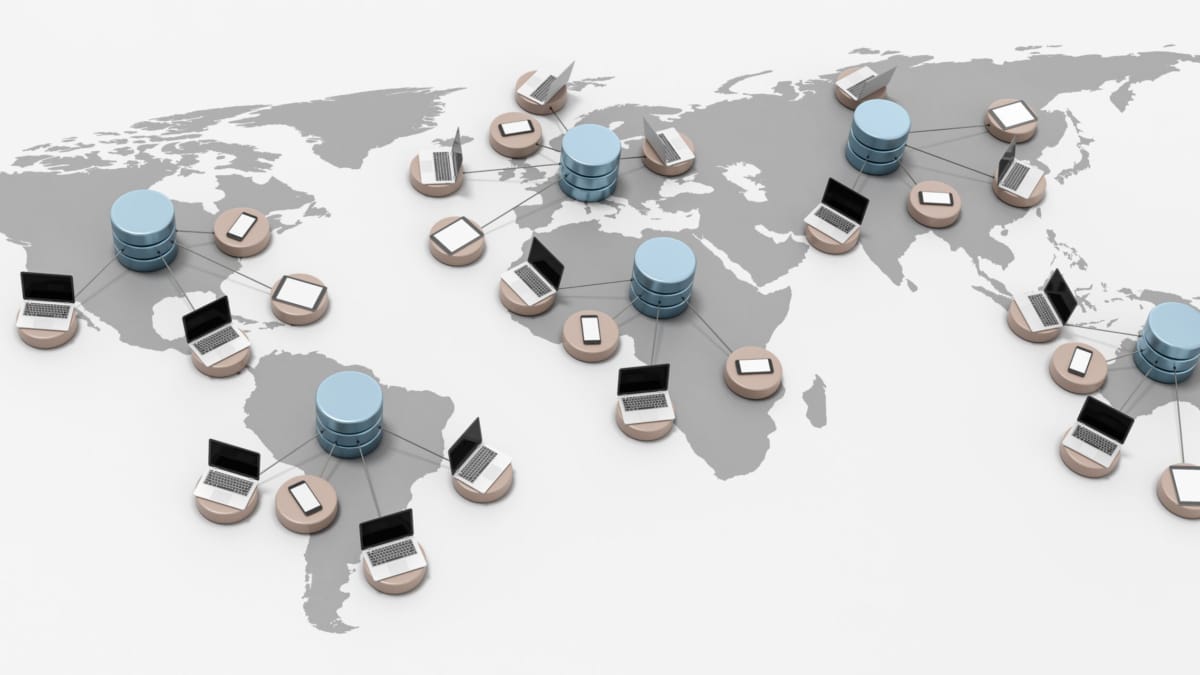
Network overlays, at their core, are virtual networks created on top of physical networks. They act as an additional layer, abstracting the underlying infrastructure and providing a flexible and scalable network environment. By decoupling the logical and physical aspects of networking, overlays enable simplified management, efficient resource utilization, and dynamic adaptation to changing requirements.

One of the key elements that make network overlays so powerful is their ability to encapsulate and transport network traffic. By encapsulating data packets within packets of a different protocol, overlays create virtual tunnels that can traverse different networks, regardless of their underlying infrastructure. This magic enables seamless communication between geographically dispersed devices and networks, bringing about a new level of connectivity.

The versatility of network overlays opens up a world of possibilities. From enhancing security through encrypted tunnels to enabling network virtualization and multi-tenancy, overlays empower organizations to build complex and dynamic network architectures. They facilitate the deployment of services, applications, and virtual machines across different environments, allowing for efficient resource utilization and improved scalability.

Network overlays have found their place in various domains. In data centers, overlays enable the creation of virtual networks for different tenants, isolating their traffic and providing enhanced security. In cloud computing, overlays play a crucial role in enabling seamless communication between different cloud providers and environments. Additionally, overlays have been leveraged in Software-Defined Networking (SDN) to enable network programmability and agility.

Highlights: Network Overlays

Overlay Networking

**Understanding Network Overlays**

– Network overlays are virtual networks built on top of physical network infrastructures. They enable organizations to abstract and separate network services from the underlying hardware, allowing for more flexible and scalable networking solutions. By using technologies like tunneling protocols and virtual LANs (VLANs), overlays facilitate the creation of isolated network segments that can be tailored to specific needs without altering the physical network.

– Organizations can expand their networks more seamlessly by creating virtual connections that don’t require additional physical infrastructure. Additionally, overlays improve network security by isolating traffic within specific segments, reducing the risk of data breaches. They also offer increased flexibility, allowing network administrators to quickly adapt to changing business requirements without disrupting existing services.

**Applications in Modern Networks**

– Network overlays are widely used in various industries, including cloud computing, data centers, and enterprise networks. In cloud environments, overlays allow for efficient resource allocation and management across distributed systems.

– Data centers use overlays to optimize traffic flow and improve redundancy, ensuring uninterrupted service. Enterprises benefit from overlays by implementing virtual private networks (VPNs) and software-defined networking (SDN) solutions, which provide enhanced control and visibility over network operations.


Data Analytics with Network Overlays

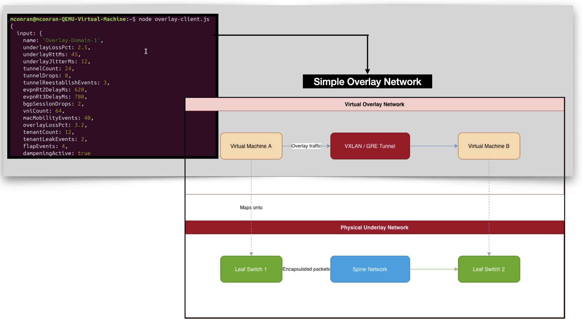
Data analytics is the intelligence layer that reveals how network overlays actually behave across dynamic, multi‑tenant fabrics. Overlays—VXLAN, NVGRE, Geneve, GRE, LISP—generate telemetry at every stage: tunnel‑health metrics, encapsulation/decapsulation latency, VTEP/edge‑node stability, underlay path symmetry, MAC/IP mobility rates, and control‑plane update frequency. Analytics ingests this telemetry to expose how overlay flows traverse the fabric under real workloads. It highlights issues that traditional monitoring misses: ECMP imbalance across tunnels, noisy endpoints causing overlay churn, underlay reconvergence silently shifting overlay paths, or latency pockets created by bursty east‑west traffic. By correlating overlay behavior with underlay routing and application performance, analytics transforms overlays from abstract logical constructs into fully observable systems.

When analytics is integrated directly with overlay control planes and orchestration systems, overlays become adaptive rather than static. Real‑time analytics feeds SDN controllers, EVPN engines, and policy orchestrators with precise state: tunnel‑latency trends, endpoint mobility patterns, VNI/VXLAN consistency, and underlay health. With this intelligence, the network can rebalance overlay tunnels, dampen unstable MAC/IP mobility, adjust endpoint placement, or pre‑emptively reroute flows away from degraded underlay segments. In multi‑site or stretched‑overlay designs, analytics validates cross‑fabric symmetry, detects drift between control‑plane instances, and predicts when overlay constructs are approaching instability thresholds. The result is an overlay fabric that learns from telemetry, optimizes itself continuously, and maintains predictable performance even during failures or heavy east‑west bursts. Data analytics transforms network overlays into self‑optimizing, feedback‑driven virtual fabrics.

Network Overlays as the Modern Fabric Abstraction

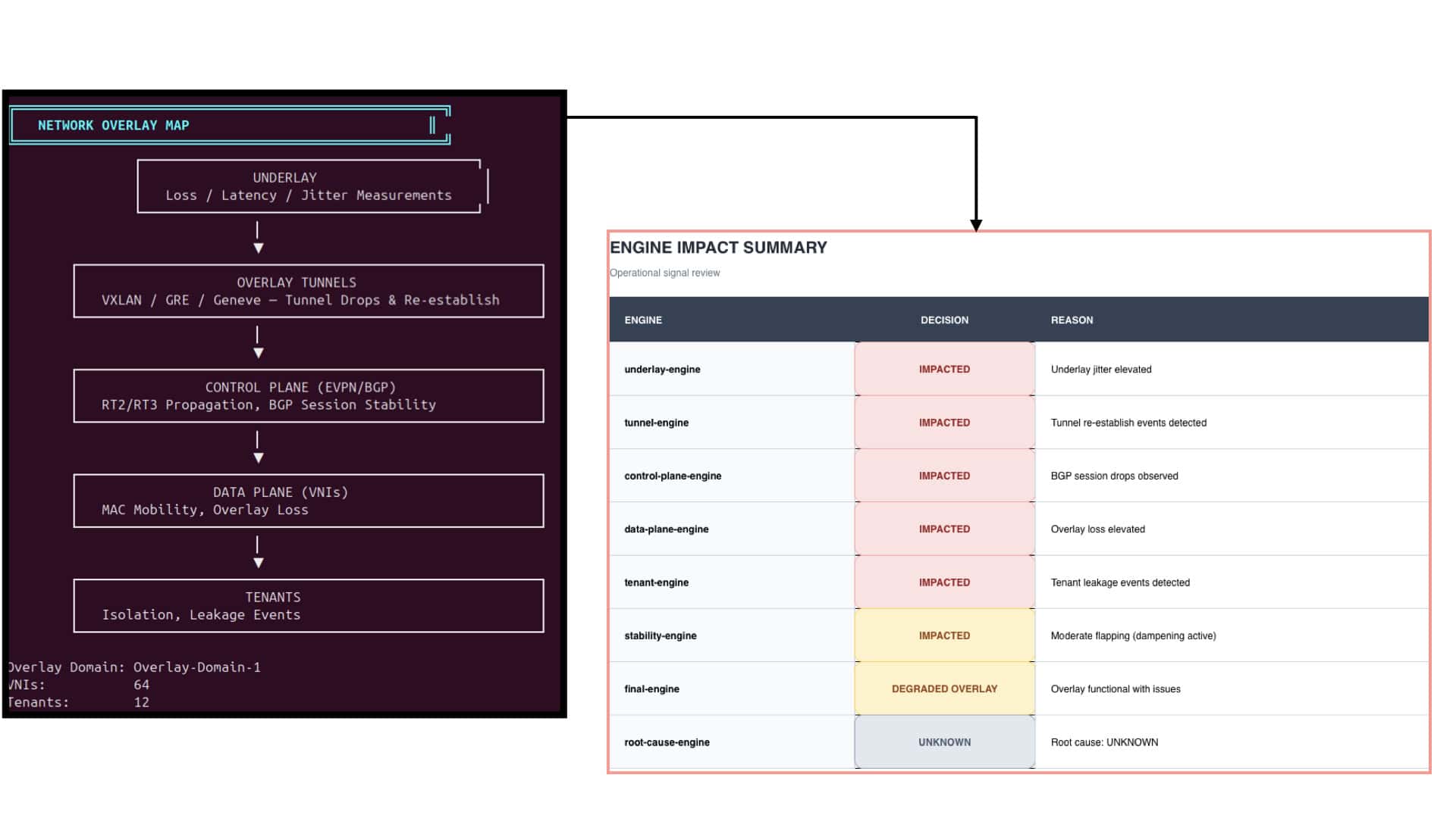
Network overlays have become the dominant way to virtualize connectivity across distributed infrastructures. Instead of relying on the physical topology to express segmentation, mobility, or tenant boundaries, overlays build a logical fabric on top of the underlay using encapsulation technologies like VXLAN, Geneve, or GRE. This separation of concerns allows operators to design scalable multi‑tenant networks without being constrained by physical layout or legacy boundaries. In practice, overlays turn the data center into a programmable canvas where tunnels, VNIs, and EVPN routes define how workloads communicate, migrate, and isolate.

The real power of modern overlays comes from the control plane, and EVPN has emerged as the industry’s preferred mechanism for distributing MAC, IP, and tenant information. EVPN Route‑Types (RT2 for MAC/IP, RT3 for IMET, RT5 for IP prefixes) allow the overlay to maintain consistent reachability even as workloads move or scale. When EVPN propagation slows or BGP sessions flap, the overlay’s “brain” becomes sluggish, causing delayed convergence, stale entries, or mobility storms. This is why overlay health is inseparable from control‑plane stability: the tunnels carry the traffic, but EVPN decides where that traffic should go.

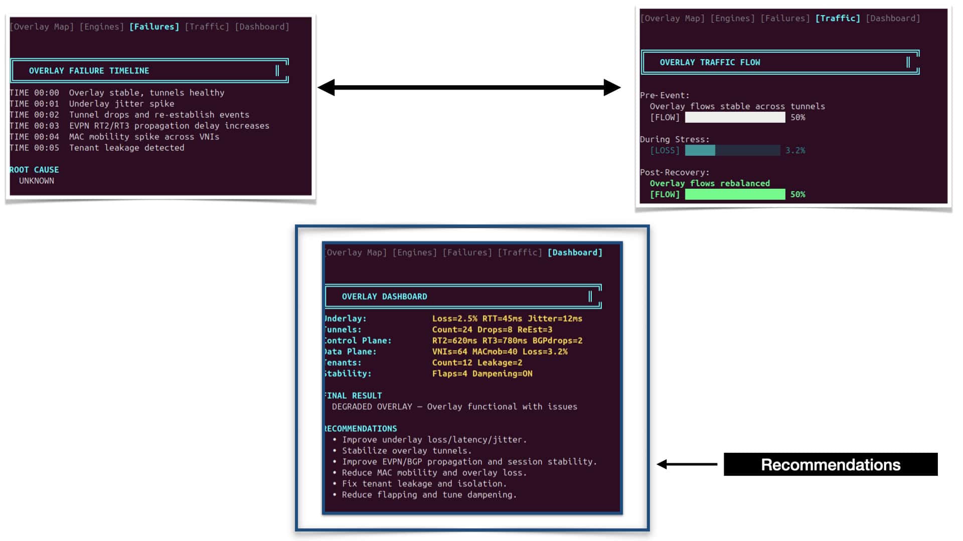
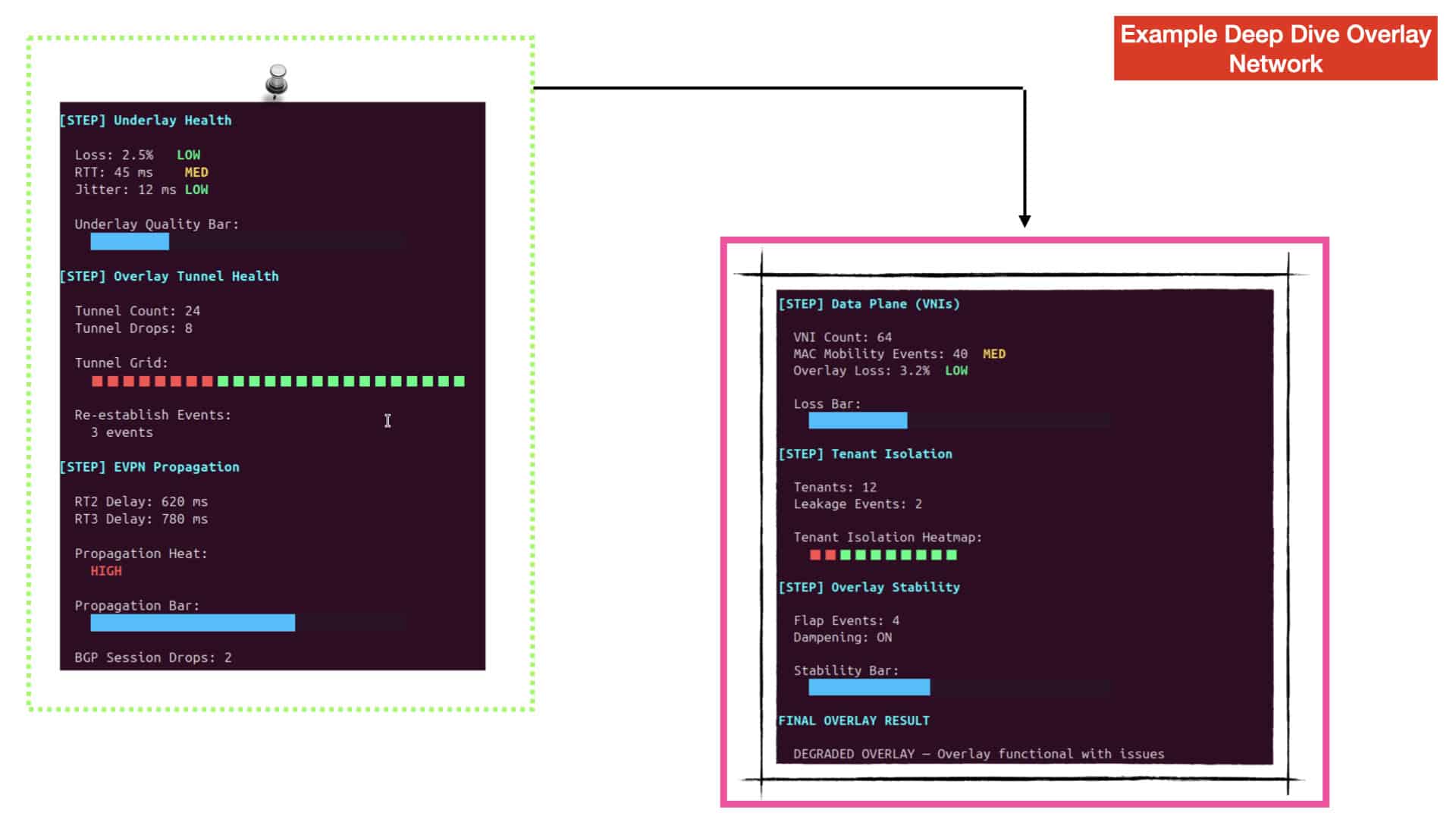
Under the hood, overlays rely on thousands of tunnels and VNIs to move encapsulated traffic across the underlay. Each tunnel represents a virtual link between nodes, and its stability directly affects tenant experience. Loss, jitter, or re‑establish events can ripple through the overlay, causing packet drops, asymmetric paths, or degraded application performance. MAC mobility events—common in virtualized environments—stress the data plane further, forcing the overlay to constantly update forwarding entries. A healthy overlay is one where tunnels remain stable, VNIs stay consistent, and mobility is absorbed without excessive churn.

As organizations expand across multiple sites, overlays increasingly span data centers, regions, and cloud edges. Multi‑domain overlays allow tenants to stretch networks across geographic boundaries while maintaining isolation and consistent policy. However, this introduces new challenges: underlay differences between sites, cross‑domain EVPN propagation, and tenant leakage risks. A multi‑domain analyzer becomes essential for understanding how each site contributes to the overall fabric health. By scoring underlay loss, overlay loss, BGP stability, and isolation per domain, operators gain a clear view of how well the distributed fabric behaves as a unified system.


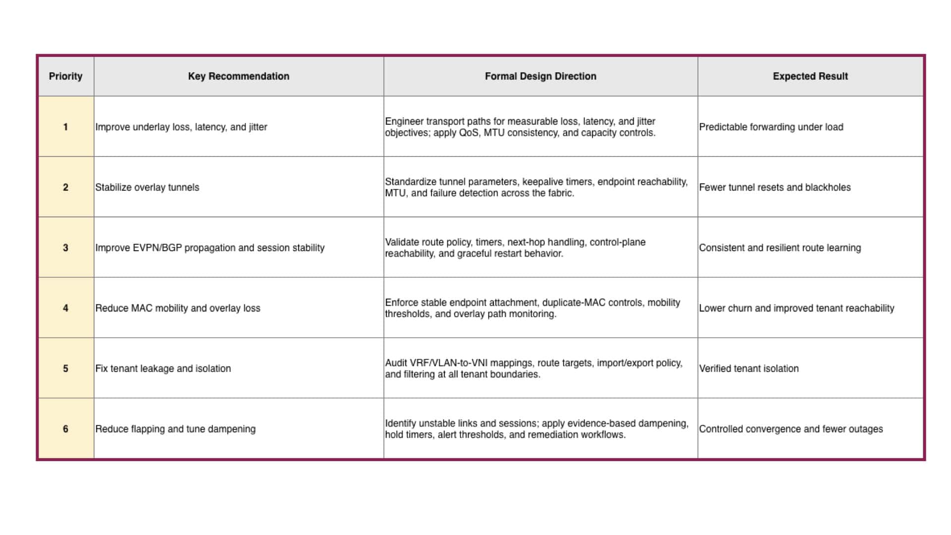
The recommendations below presents a structured design framework for optimizing network overlays, organized by priority and outcome. It captures the essence of how overlay reliability depends on disciplined engineering across underlay, control‑plane, and data‑plane layers. Each recommendation builds on the previous one: starting with improving underlay transport quality—loss, latency, and jitter—to ensure predictable forwarding under load. Once the foundation is stable, the focus shifts to overlay tunnel consistency, standardizing parameters and failure detection to prevent resets and blackholes.

The third and fourth priorities move deeper into the overlay’s intelligence and behavior. They emphasize EVPN/BGP propagation stability and MAC mobility control, ensuring route learning remains resilient and tenant reachability unaffected by churn. These steps transform the overlay from a reactive system into a self‑healing fabric capable of maintaining state during transitions.

The fifth recommendation addresses tenant isolation, a critical security and operational boundary in multi‑tenant overlays. By auditing VRF/VLAN‑to‑VNI mappings and route‑target policies, engineers can guarantee that tenants remain logically separated even as overlays stretch across fabrics. This is where overlays prove their worth—providing segmentation without physical constraints.

Finally, the sixth priority—reducing flapping and tuning dampening—ties the entire design together. It introduces evidence‑based stability controls, hold timers, and remediation workflows that prevent transient events from cascading into outages. Together, these six priorities form a holistic blueprint for overlay design: a progression from physical reliability to logical precision, ensuring controlled convergence, fewer outages, and a truly predictable virtual fabric.Tunneling and Encapsulation

### What is Tunneling?

Tunneling is a technique used to transfer data between networks securely. It involves encapsulating a network protocol within packets carried by the native protocol of another network. This process allows data to travel across a network that might not natively support the original protocol. Tunneling is often used in Virtual Private Networks (VPNs) to ensure that data is securely transmitted over potentially insecure networks, such as the internet.

Example – IPv6 Tunneling?

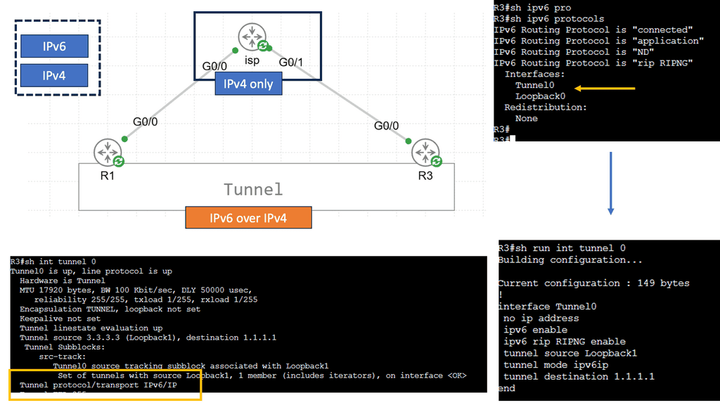
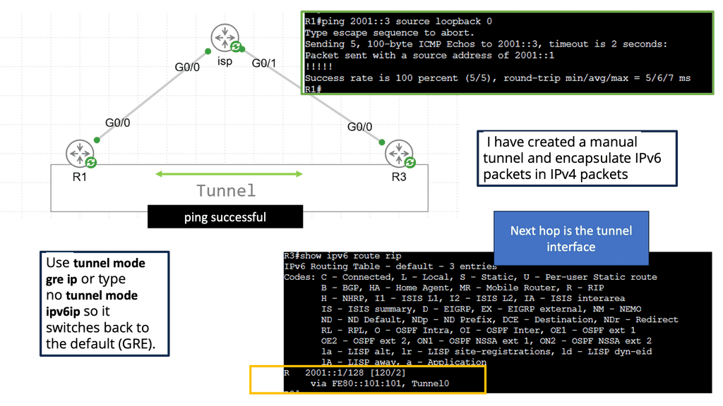
IPv6 tunneling is a mechanism that allows IPv6 packets to be encapsulated within IPv4 packets. This method is essential for transmitting IPv6 traffic over an IPv4 infrastructure. By doing so, it enables networks to adopt IPv6 without the immediate need to replace existing IPv4 hardware and software. This encapsulation process ensures that IPv6 data reaches its destination seamlessly, even in environments where IPv4 is still prevalent.

### Understanding Encapsulation

Encapsulation is a fundamental concept in networking that plays a crucial role in how data is transmitted across networks. At its core, encapsulation involves wrapping data with protocol information so that it can be properly routed and interpreted by the receiving systems. This process allows different types of data to be sent over a network in a seamless and efficient manner. In this blog post, we’ll explore the intricacies of encapsulation and delve into two popular protocols: Generic Routing Encapsulation (GRE) and Virtual Extensible LAN (VXLAN).

Example – GRE in Modern Networking

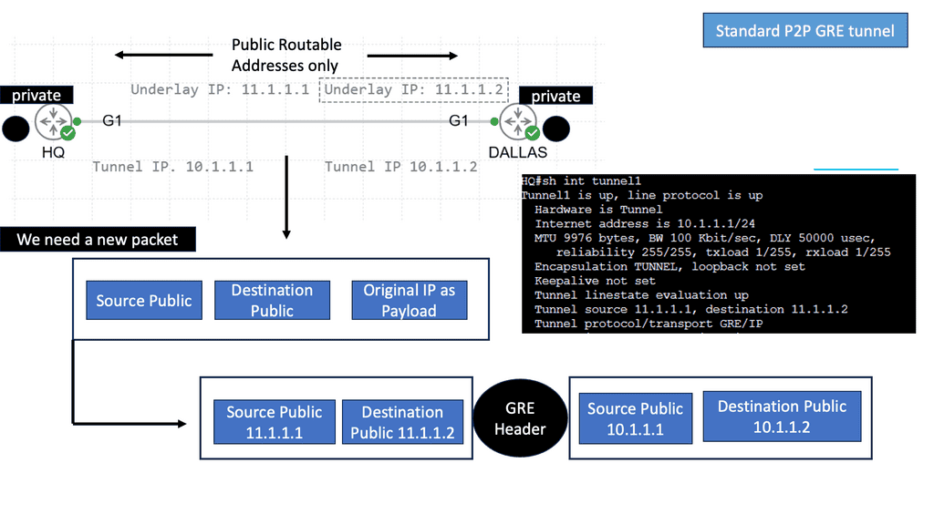
Generic Routing Encapsulation, commonly referred to as GRE, is a tunneling protocol developed by Cisco. GRE is widely used to encapsulate a wide variety of network layer protocols inside virtual point-to-point links. This versatility makes it an invaluable tool in modern networking, allowing for the creation of direct connections between different network nodes, even across diverse network architectures.

Example VPN Technology: GETVPN

**Understanding the Basics**

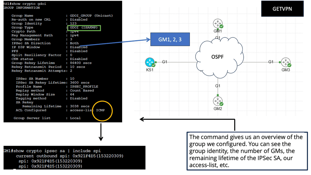
GETVPN, or Group Encrypted Transport VPN, is a protocol designed to secure communication over IP networks. Unlike traditional VPNs that create point-to-point tunnels, GETVPN uses a group key distribution model. This means that data can be securely transmitted between multiple locations without the need to establish individual tunnels. By leveraging the power of group keys, GETVPN provides a scalable and efficient solution for enterprises looking to protect their data.

**Key Features of GETVPN**

One of the standout features of GETVPN is its ability to encrypt traffic without altering the underlying routing infrastructure. This is achieved through its unique architecture that separates the encryption process from the routing process. Moreover, GETVPN supports multicast traffic, making it an ideal choice for organizations that rely on real-time data distribution, such as video conferencing or live streaming services. Additionally, GETVPN enhances network performance by reducing the complexity typically associated with maintaining numerous VPN tunnels.

**Security and Performance Benefits**

The primary objective of GETVPN is to provide robust security while maintaining optimal performance. By using a centralized key server, GETVPN ensures that all devices within the network receive the same group key, allowing for seamless and secure communication. This method not only simplifies the management of encryption keys but also reduces the risk of key compromise. Furthermore, GETVPN’s ability to handle multicast traffic efficiently means that organizations can enjoy high-speed data transmission without compromising on security.

**Overlay Network Types**

Overlay networks are computer networks that are layered on top of other networks (logical instead of physical). They differ from the traditional OSI layered network model and almost always assume that the underlay network is an IP network. These technologies include VXLAN, BGP VPNs, Layer 2 and Layer 3, and IP over IP, such as GRE or IPsec tunnels. Overlay networks, such as SD-WAN, use IP over IP technologies.

The overlay network (SDN overlay) allows multiple network layers to be run on top of each other, adding new applications and improving security. Multiple secure overlays can be created using software over existing networking hardware infrastructure by making virtual connections between two endpoints. In the cloud, endpoints can be physical locations, such as network ports, or logical locations, such as software addresses.

Note: Virtual Tunnels & Software Tags

Software tags, labels, and encryption create a virtual tunnel between two network endpoints. End users must be authenticated to use the connection if encryption is used. Like a phone system, the technology can be considered endpoints with identification tags. An identification tag or number can be used to locate a device in a network, creating virtual connections.

**Benefits of Network Overlays**

1. Simplified Network Management: With network overlays, organizations can manage their networks centrally, using software-defined networking (SDN) controllers. This centralized approach eliminates the need for manual configuration and reduces the complexity associated with traditional network management.

2. Enhanced Scalability: Network overlays enable businesses to scale their networks easily by provisioning virtual networks on demand. This flexibility allows rapid deployment of new services and applications without physical network reconfiguration.

3. Improved Security: Network overlays provide an additional layer of security by encapsulating traffic within virtual tunnels. This isolation helps prevent unauthorized access and reduces the risk of potential security breaches, especially in multi-tenant environments.

4. Interoperability: Network overlays can be deployed across heterogeneous environments, enabling seamless connectivity between different network types, such as private and public clouds. This interoperability extends the network across multiple locations and integrates various cloud services effortlessly.

Service Mesh & Network Overlays

### What is a Service Mesh?

At its core, a service mesh is a network overlay that provides a range of services like traffic management, load balancing, security, and observability to applications without requiring changes to the code. It consists of a data plane and a control plane. The data plane handles the actual communication between services through lightweight proxies, while the control plane configures and manages these proxies.

### Key Benefits of Deploying a Service Mesh

One of the primary benefits of deploying a service mesh is enhanced security. With features such as mutual TLS, service mesh can encrypt the data in transit and ensure that only the intended services communicate with each other. Additionally, service mesh offers advanced traffic management capabilities, such as intelligent routing and retries, which enhance the resilience of applications. Observability is another significant advantage, as service mesh provides detailed metrics and tracing capabilities, enabling teams to monitor the health and performance of their applications closely.

### Service Mesh and Network Overlay

The concept of a network overlay is integral to understanding service mesh. In essence, a network overlay abstracts the complexity of the underlying network by creating a virtual network on top of the physical network infrastructure. This abstraction allows service mesh to seamlessly manage service communication across diverse environments, be it on-premises, cloud, or hybrid setups. By implementing a service mesh, organizations can achieve consistent networking policies and configurations across their distributed services.

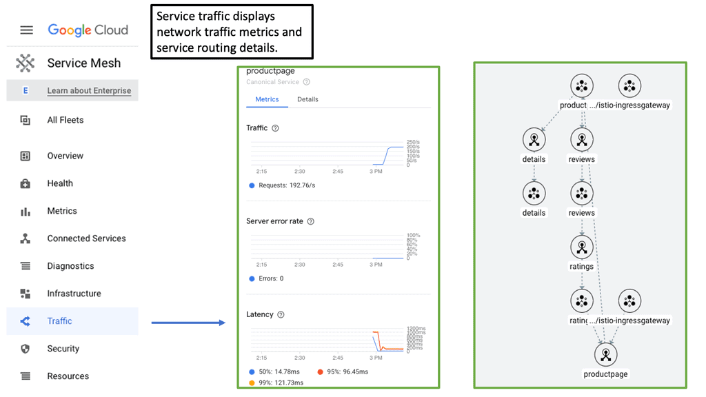
Service Mesh Google Cloud

**How Cloud Service Mesh Works**

At its core, a cloud service mesh consists of a data plane and a control plane. The data plane is responsible for handling the actual data transfer between services, while the control plane manages the policies and configurations that govern this communication. By deploying sidecar proxies alongside each microservice, the service mesh can intercept and manage all network traffic, ensuring that communication is secure, reliable, and observable.

**Key Benefits of Cloud Service Mesh**

1. **Enhanced Security:** One of the primary advantages of a cloud service mesh is the ability to enforce security policies consistently across all microservices. With features like mutual TLS (mTLS) for encryption, service mesh ensures that data in transit is secure, reducing the risk of breaches.

2. **Observability and Monitoring:** Service mesh provides comprehensive visibility into service-to-service communication. By collecting metrics, logs, and traces, it allows for detailed monitoring and troubleshooting, enabling teams to quickly identify and resolve issues.

3. **Traffic Management:** Advanced traffic management capabilities, such as load balancing, traffic splitting, and circuit breaking, are built into the service mesh. These features ensure that services can handle variable loads and maintain high availability and performance.

**Implementing a Cloud Service Mesh**

Adopting a cloud service mesh requires careful planning and consideration. Organizations should start by evaluating their current architecture and identifying key areas where a service mesh can bring immediate benefits. It’s also essential to choose the right service mesh solution, such as Istio, Linkerd, or Consul, based on specific needs and compatibility with the existing environment.

**Challenges and Considerations**

While the advantages of a cloud service mesh are clear, there are also challenges to consider. Implementing a service mesh introduces additional complexity and overhead, which can impact performance if not managed properly. It’s crucial to have a thorough understanding of the service mesh architecture and to invest in proper training and support for the team.

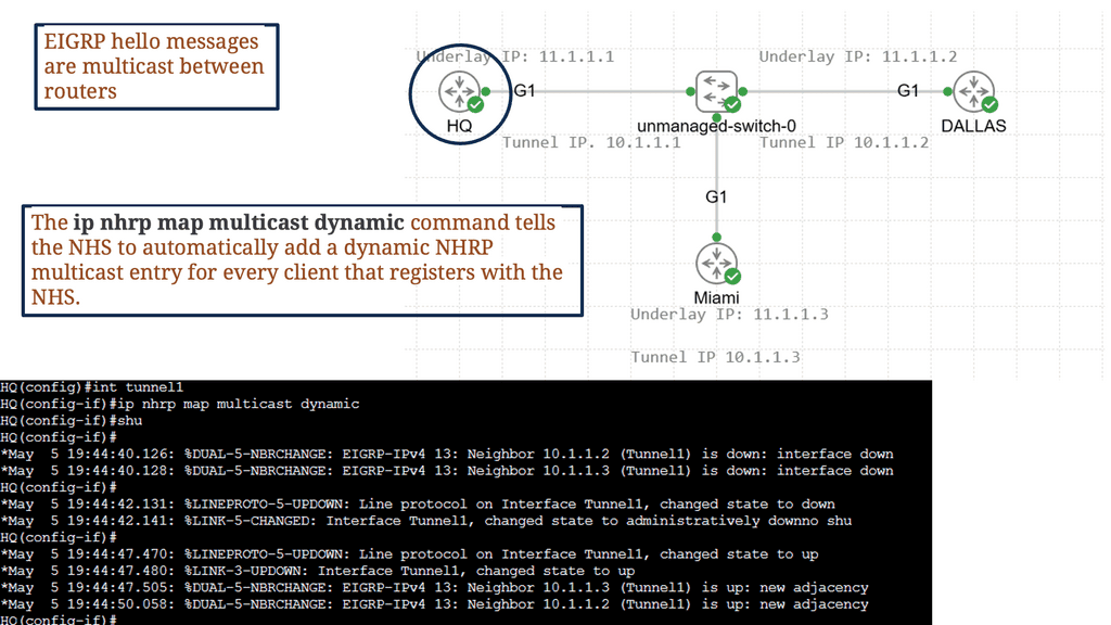
Example Technology: EIGRP and GRE

In simple terms, GRE is a tunneling protocol that encapsulates various network layer protocols within IP packets. It establishes a virtual point-to-point connection between different networks, facilitating data transmission across disparate networks. Encapsulating packets within GRE headers allows for secure and efficient communication.

To establish a GRE tunnel, two endpoints are required: a source and a destination. The source endpoint encapsulates the original packet by adding a GRE header, while the destination endpoint decapsulates the packet and forwards it to the appropriate destination. This encapsulation process involves adding an extra IP header, which allows the packet to traverse the network as if it were a regular IP packet.

GRE configuration

Networking approach based on overlays

Different overlay networking approaches are often debated in the SDN community. Depending on the technology, some software-only solutions may not be able to integrate at the chip level. The layering of software and processing in overlay networking has been criticized for creating performance overhead. Network overlays are controlled by SDN controllers using the OpenFlow protocol, which requires specific software code or “agents” to be installed.

A -) Change in Traffic Patterns

Thanks to the paradigm shift toward cloud computing, a host of physical servers and I/O devices can host multiple virtual servers that share the same logical network despite being in remote locations. In contrast to the traditional north-south direction of data traffic within data centers, virtualization has facilitated more significant east-west data traffic. Communication between servers and applications within a data center is known as east-west traffic.

In corporate networks or on the Internet, much of the data required by the end user involves more complex data that requires preprocessing. Using a web server (via an app server) to access a database as an example of east-west traffic, we can demonstrate the need for preprocessing.

B -) The birth of network overlays

Network virtualization overlays have become the de facto solution for addressing the problems just described regarding data center expansion. Overlays allow existing network technologies to be abstracted, extending the capabilities of classic networks.

Networking has been using overlays for quite some time. As their name implies, overlays were developed to overcome the disadvantages of conventional networks. An overlay is a tunnel that runs on a physical network infrastructure.

MPLS and GRE Encapsulation

Following MPLS- and GRE-based encapsulations in the 1990s, other tunneling technologies, such as IPsec,8 6in4,9, and L2TPv3,10, also gained popularity. For example, 6in4 tunnels were used to carry payloads over a transport network that could not support the payload type. These tunnels were utilized for security purposes, simplifying routing lookups, or carrying payloads over unsupported transport networks.

Example of GRE Encapsulation

**The Basics of GRE**

At its core, GRE functions as a tunneling protocol that encapsulates a payload, or the original packet, within another packet. This encapsulation allows different types of network layer protocols to be transmitted over a single protocol, such as IP. GRE is particularly useful in scenarios where diverse network architectures need to communicate seamlessly, as it provides a universal solution for protocol encapsulation.

**Advantages of Using GRE**

One of the primary benefits of GRE is its simplicity and versatility. Unlike other tunneling protocols, GRE does not require extensive configuration, making it an attractive option for network administrators. Additionally, GRE supports multicast packets, which is beneficial for applications like streaming and online conferencing. The protocol’s lightweight nature ensures minimal overhead, contributing to efficient data transmission.

**How GRE Operates**

Understanding how GRE operates is essential for leveraging its full potential. When a packet is sent through a GRE tunnel, it is encapsulated with a GRE header and another IP header. This process effectively creates a ‘tunnel’ through which the original data can travel securely and efficiently. The GRE header contains critical information that guides the packet to its destination, ensuring seamless delivery.

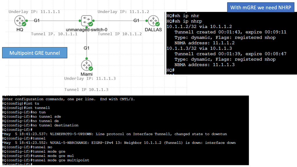
Example – Multipoint GRE with DMVPN

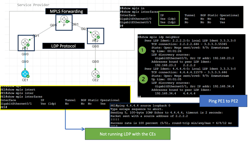
Understanding MPLS Forwarding

MPLS (Multi-Protocol Label Switching) forwarding is used in modern computer networks to route data packets efficiently. Unlike traditional IP routing, which relies on complex table lookups, MPLS forwarding utilizes labels to simplify and expedite packet forwarding. These labels act as virtual shortcuts, enabling faster and more streamlined transmission. To comprehend MPLS forwarding in action, let’s consider a hypothetical scenario of a multinational corporation with branch offices in different countries.

The organization can establish a private network that connects all its branches securely and efficiently by implementing MPLS forwarding. MPLS labels are assigned to packets at the ingress router and guide them through the network, ensuring reliable and optimized data transmission. This enables seamless communication, data sharing, and collaborative workflows across geographically dispersed locations.

What is the LDP Protocol?

The LDP protocol, short for Label Distribution Protocol, is a signaling protocol used in Multiprotocol Label Switching (MPLS) networks. It facilitates the exchange of label mapping information between Label Switching Routers (LSRs), allowing them to establish forwarding equivalence classes (FECs) and efficiently forward data packets.

Label Distribution: The core functionality of the LDP protocol lies in its ability to distribute and assign labels to network paths. These labels help LSRs establish predetermined forwarding paths, enabling faster and more efficient packet forwarding.

Traffic Engineering: Through its Traffic Engineering (TE) extensions, the LDP protocol allows network administrators to optimize the utilization of network resources. Dynamically adjusting label assignments and traffic flows enables better load balancing and network performance.

Network Overlays and Virtual Networks

Network overlays have emerged as a powerful solution to address the challenges of modern networks’ increasing complexity. This blog post will explore network overlays, their benefits, and how they improve connectivity and scalability in today’s digital landscape.

Network overlays are virtual networks that run on physical networks, providing an additional abstraction layer. They allow organizations to create logical networks independent of the underlying physical infrastructure. This decoupling enables flexibility, scalability, and simplified management of complex network architectures.

Virtual Network Services

Network overlays refer to virtualizing network services and infrastructure over existing physical networks. By decoupling the network control plane from the underlying hardware, network overlays provide a layer of abstraction that simplifies network management while offering enhanced flexibility and scalability. This approach allows organizations to create virtual networks tailored to their specific needs without the constraints imposed by physical infrastructure limitations.

Creating an overlay tunnel

A network overlay is an architecture that creates a virtualized network on top of an existing physical network. It allows multiple virtual networks to run independently and securely on the same physical infrastructure. Network overlays are a great way to create a more secure and flexible network environment without investing in new infrastructure.

Network overlays can be used for various applications, such as creating virtual LANs (VLANs), virtual private networks (VPNs), and multicast networks. For example, we have DMVPN (Dynamic Multipoint VPN), with several DMVPN phases providing a secure network technology that allows for multiple sites’ efficient and secure connection.

Example: Cisco DMVPN

### How DMVPN Works

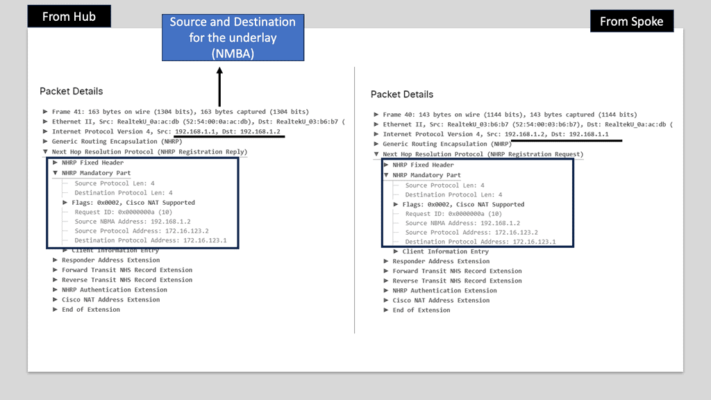
At its core, DMVPN simplifies the creation of secure VPN connections between branch offices and remote users. It leverages a hub-and-spoke architecture but with a dynamic twist. Unlike traditional VPNs that require complex configurations for each connection, DMVPN allows spoke-to-spoke communication without routing all traffic through the hub. This is achieved using multipoint GRE tunnels and Next Hop Resolution Protocol (NHRP), enabling direct and efficient communication paths.

### Benefits of Implementing DMVPN

One of the standout benefits of DMVPN is its scalability. As organizations grow, adding new sites or remote users becomes seamless. The reduction in configuration complexity translates to lower operational costs and quicker deployment times. Moreover, DMVPN enhances network performance by reducing latency and improving bandwidth utilization through direct communication paths. Security is another critical advantage, as DMVPN supports various encryption protocols to ensure that data remains protected across the network.

### DMVPN vs Traditional VPN Solutions

Comparing DMVPN to traditional VPN solutions highlights its superior flexibility and efficiency. While traditional VPNs often require manual configuration for each new connection, DMVPN automates this process, reducing the risk of human error. Additionally, DMVPN’s ability to support dynamic routing protocols ensures optimal routing paths, something static VPNs struggle with. This makes DMVPN particularly appealing for organizations with a dynamic and expanding network topology.

In addition, they can segment traffic and provide secure communication between two or more networks. As a result, network overlays allow for more efficient resource use and provide better performance, scalability, and security.

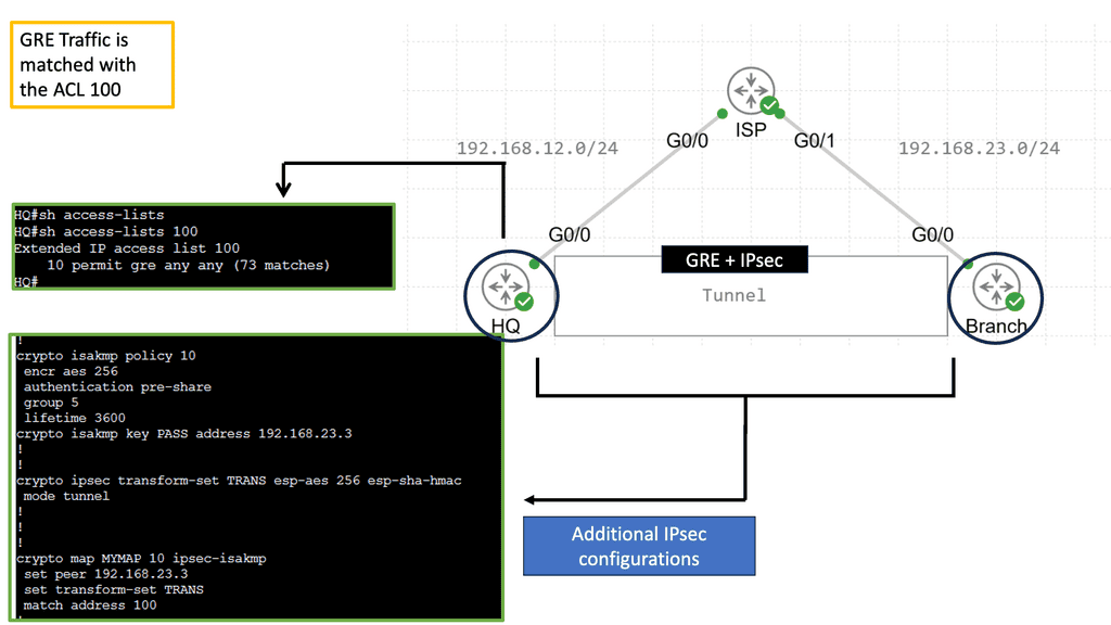
Securing and overlay: GRE and IPSec

When combined, GRE and IPSec create a robust security infrastructure that addresses tunneling and encryption requirements. GRE tunnels establish secure connections between networks, enabling the transmission of encapsulated packets. IPSec then encrypts these packets, ensuring that data remains confidential and protected from interception. This powerful combination allows organizations to establish secure and private communication channels over untrusted networks like the Internet.

The utilization of GRE and IPSec brings numerous benefits to network security. Firstly, organizations can establish secure and scalable virtual private networks (VPNs) using GRE tunnels, allowing remote employees to access internal resources securely. Secondly, IPSec encryption protects data during transmission, safeguarding against eavesdropping and tampering. Additionally, the combination of GRE and IPSec facilitates secure communication between branch offices, enabling seamless collaboration and data sharing.

GRE with IPsec

Network Overlays Enhanced Connectivity:

Network overlays improve connectivity by enabling seamless communication between different network domains. By abstracting the underlying physical infrastructure, overlays facilitate the creation of virtual network segments that can span geographical locations, data centers, and cloud environments. This enhanced connectivity promotes better collaboration, data sharing, and application access within and across organizations.

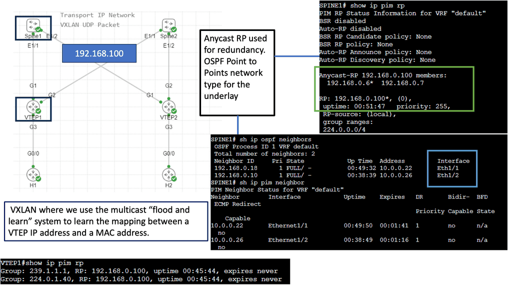
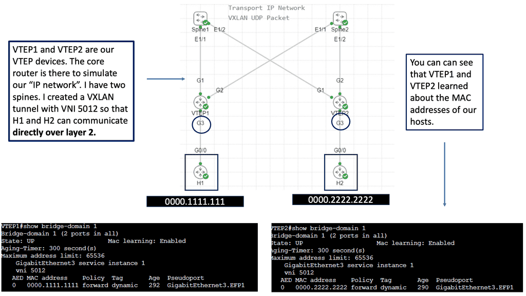
Example: VXLAN Flood and Learn

Unveiling Flood and Learn

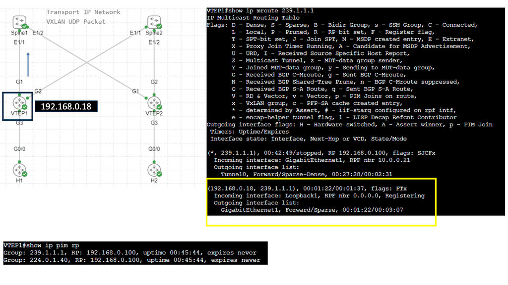
– Flood and learn is a fundamental concept in VXLAN that allows hosts to efficiently learn the MAC addresses of virtual machines within the same VXLAN segment. When a host receives an unknown unicast, it floods the packet to all other hosts within the VXLAN segment. The destination host then learns the MAC address and updates its forwarding table accordingly. This process ensures that subsequent packets are directly forwarded to the destination host, minimizing unnecessary flooding.

– In traditional flood and learn implementations, flooding occurs using broadcast or unicast methods, which can lead to significant network congestion. However, by leveraging multicast, VXLAN flood and learn achieve enhanced efficiency and scalability. Multicast groups are established for each VXLAN segment, ensuring unknown unicast packets are only flooded to hosts subscribed to the respective multicast group. This targeted flooding reduces network overhead and optimizes bandwidth utilization.

– VXLAN flood and learn with multicast opens up a world of possibilities in various networking scenarios. From data center virtualization to cloud computing environments, this approach offers benefits such as improved performance, reduced network latency, and simplified network management. It enables seamless communication between virtual machines, even across different physical hosts or clusters, enhancing the flexibility and scalability of virtualized networks.

Understanding IPv6 Tunneling

IPv6 tunneling is a mechanism that encapsulates IPv6 packets within IPv4 packets, allowing them to traverse an IPv4 network. This enables communication between IPv6-enabled devices across IPv4-only networks. By encapsulating IPv6 packets within IPv4 packets, tunneling provides a practical solution for the coexistence of both protocols.

**Types of IPv6 Tunneling**

There are several methods for implementing IPv6 tunneling over IPv4, each with advantages and considerations. Let’s explore some popular types:

Manual Tunneling: Manual tunneling involves configuring tunnels between IPv6 and IPv4 endpoints. This method requires configuring tunnel endpoints and addressing them, making it suitable for smaller networks or specific scenarios.

Automatic tunneling, also known as 6to4 tunneling, allows for automatically creating IPv6 tunnels over IPv4 networks. It utilizes a 6to4 relay router to facilitate communication between IPv6 and IPv4 networks. Automatic tunneling is relatively easy to set up and does not require manual configuration.

Teredo Tunneling: Teredo tunneling is a mechanism that enables IPv6 connectivity over IPv4 networks, even behind Network Address Translations (NATs). It provides a way for IPv6 traffic to traverse NAT devices by encapsulating IPv6 packets within UDP packets. Teredo tunneling is particularly useful for home networks and scenarios where IPv6 connectivity is limited.

Advanced Topic

DMVPM:

The underlay network forms the foundation of any DMVPN deployment. It consists of the physical infrastructure that connects the various endpoints. The underlay network ensures reliable and efficient data transmission from routers and switches to cables and network protocols. Key considerations in establishing a robust underlay include network design, redundancy, Quality of Service (QoS) policies, and security measures.

DMVPN truly shines in the overlay network, built on top of the underlay. It enables secure and efficient communication between remote sites, regardless of their physical locations. By leveraging multipoint GRE tunnels and dynamic routing protocols such as EIGRP or OSPF, DMVPN establishes a mesh network that seamlessly connects all endpoints. This overlay architecture eliminates the need for complex and static point-to-point VPN configurations, providing scalability and ease of management.

Benefits and Use Cases:

DMVPN offers a plethora of benefits and is extensively used across various industries. Its ability to provide secure and scalable connectivity makes it ideal for enterprises with multiple branch offices. By utilizing DMVPN, organizations can optimize their network infrastructure, reduce costs associated with traditional VPN solutions, and enhance overall network performance. Additionally, DMVPN enables seamless integration with cloud services and facilitates secure remote access for teleworkers.

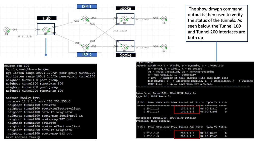
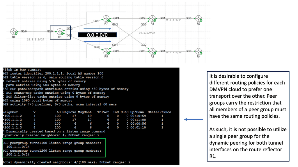
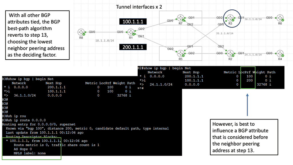
Introducing Single Hub Dual Cloud

The single-hub dual cloud architecture takes DMVPN’s capabilities to the next level. In this setup, a central hub connects to two separate cloud service providers simultaneously, forming redundant paths for traffic. This redundancy ensures high availability and fault tolerance, making it an attractive option for businesses with critical network requirements.

Implementing DMVPN with a single hub dual cloud configuration offers several advantages. Firstly, it enhances network resilience by providing built-in failover capabilities. In a cloud service provider outage, traffic can seamlessly transition to the alternate cloud, minimizing downtime. Additionally, this architecture improves network performance through load balancing, distributing traffic across multiple paths for optimal utilization.

Related: Before you proceed, you may find the following helpful:

  1. Data Center Topologies
  2. SD WAN Overlay
  3. Nexus 1000v
  4. SDN Data Center
  5. Virtual Overlay Network
  6. SD WAN SASE

Highlights: Network Overlays

Supporting distributed application

There has been a significant paradigm shift in data center networks. This evolution has driven network overlays known as tunnel overlay, bringing several new requirements to data center designs. Distributed applications are transforming traffic profiles, and there is a rapid rise in intra-DC traffic ( East-West ).

We designers face several challenges in supporting this type of scale. First, we must implement network virtualization with the overlay tunnel for large cloud deployments.

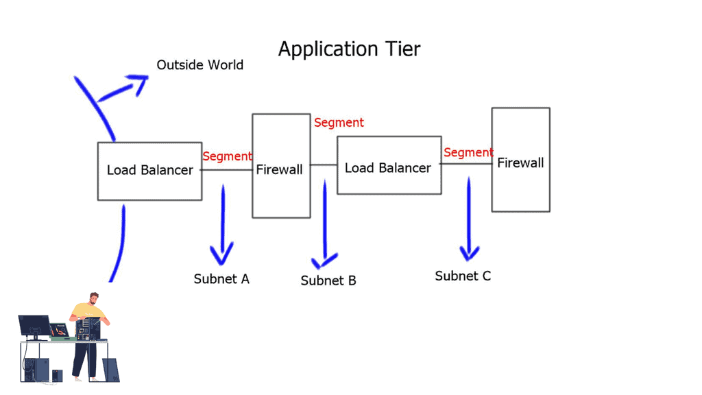
Suppose a customer requires a logical segment per application, and each application requires load balancing or firewall services between segments. In that case, having an all-physical network using traditional VLANs is impossible. The limitations of 4000 VLANS and the requirement for stretched Layer 2 subnets have pushed designers to virtualize workloads over an underlying network.

Concepts of network Virtualization

Network virtualization involves dividing a single physical network into multiple virtual networks. Virtualizing a resource allows it to be shared by various users. Numerous virtual networks have emerged over the decades to satisfy different needs. 

A primary distinction between these different types is their model for providing network connectivity. Networks can provide connectivity via bridging (L2) or routing (L3). Thus, virtual networks can be either virtual L2 networks or virtual L3 networks.

Virtual networks started with the Virtual Local Area Network (VLAN). First, the VLAN was invented to lessen the unnecessary chatter in a Layer 2 network by isolating applications from their noisy neighbors. Then VLAN was then pushed into the world of security.

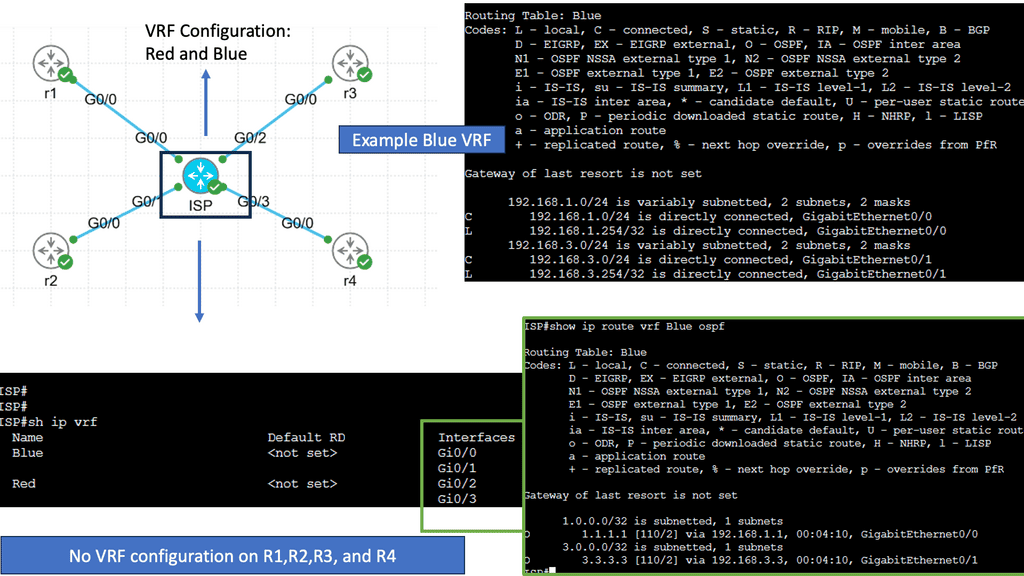
Then, we had Virtual Routing and Forwarding (VRF). The virtual L3 network was invented along with the L3 Virtual Private Network (L3VPN) to solve the problem of interconnecting geographically disparate enterprise networks over a public network. 

Example VRF Technology

  • VXLAN vs VLAN

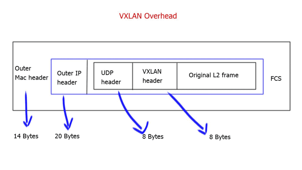
One of the first notable differences between VXLAN and VLAN was increased scalability. The VXLAN ID is 24 bits, enabling you to create up to 16 million isolated networks. This overcomes the limitation of VLANs having the 12-bit VLAN ID, which enables only a maximum of 4094 isolated networks.

Tunnel Overlay
Multiple segments per application and the need for a tunnel overlay,

What are the drawbacks of network overlays, and how does it affect network stability?

Control Plane Interaction

Tunneled network overlays

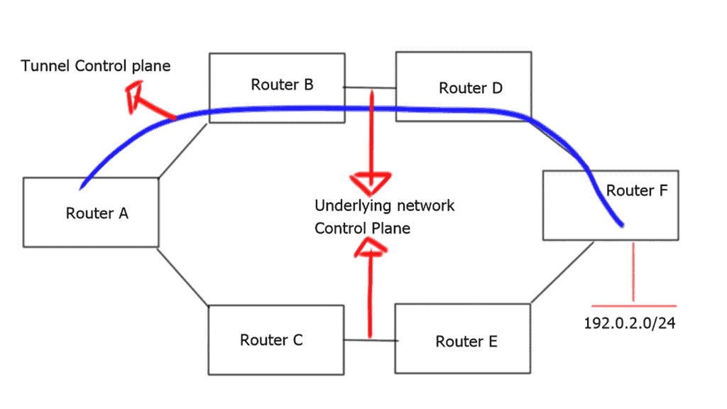
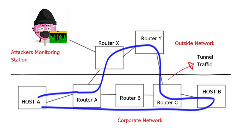
Virtualization adds a level of complexity to the network. Consider the example of a standard tunnel. We are essentially virtualizing workloads over an underlying network. From a control plane perspective, there must be more than one control plane.

This results in two views of the network’s forwarding and reachability information—a view from the tunnel endpoints and a view from the underlying network. The control plane may be static or dynamic and provides reachability through the virtual topology on top of it, which provides reachability to the tunnel endpoints.

overlay tunnel
The overlay tunnel and potential consequences.

Router A has two paths to reach 192.0.2.0/24. Already, we have the complexity of influencing and managing what traffic should and shouldn’t go down the tunnel. Modifying metrics for specific destinations will influence path selection, but this comes with additional configuration complexity and policies’ manual management.

The incorrect interaction configuration between two control planes may cause a routing loop or suboptimal routing through the tunnel interfaces. The “routers in the middle” and the “routers at tunnel edges” have different views of the network – increasing network complexity.

**A key point: Not an independent topology**

These two control planes may seem to act independently but are not independent topologies. The control plane of the virtual topology relies heavily on the control plane of the underlying network. These control planes should not be allowed to interplay freely, as both can react differently to inevitable failures. The timing of the convergence process and how quickly each control plane reacts may be the same or different.

The underlying network could converge faster or slower than the overlaying control plane, affecting application performance. Design best practice is to design the network overlays control plane so that it detects and reacts to network failures faster than the underlying control plane or have the underlying control plane detect and respond faster than the network overlays control plane.

VXLAN Challenge: Encapsulation overhead

Every VXLAN packet originating from the end host and sent toward the IP core will be stamped with a VXLAN header. This leads to an additional 50 bytes per packet from the source to the destination server. If the core cannot accommodate the greater MTU size or the Path MTU is broken, the packet may be fragmented into smaller pieces. Also, the VXLAN header must be encapsulated and de-encapsulated on the virtual switch, which takes up computing cycles. Both of these are problematic for network performance.

vxlan overhead
VXLAN overhead.

Security in a tunnel overlay

Tunnels and network overlays have many security flaws. The most notable is that they hide path information. A tunnel can pass one route on one day and take another path on a different day, and the change of path may be unknown to the network administrator. Traditional routing is hop-by-hop; every router decides where the traffic should be routed.

However, independent hop-by-hop decisions are not signaled or known by the tunnel endpoints. As a result, an attacker can direct the tunnel traffic via an unintended path where the rerouted traffic can be monitored and snooped.

VXLAN security

Tunneled traffic hides from any policies or security checkpoints. Many firewalls have HTTP port 80 open to support web browsing. This can allow an attacker to tunnel traffic in an HTTP envelope, bypassing all the security checks. There are also several security implications if you are tunneling with GRE.

First, GRE does not perform encryption or authentication on any part of the data journey. The optional 32-bit tunnel key for identifying individual traffic flows can easily be brute-forced due to the restriction of 2×32 number combinations.

Finally, it implements the sequence number used to provide a method of in-order delivery poorly. These shortcomings have opened up to several MTU-based and GRE packet injection attacks.

STP and Layer 2 attacks

VXLAN extends layer 2 domains across layer 3 boundaries, resulting in more extensive layer 2 flat networks. Regarding intrusion, the attack zones become much more significant as we connect up to two remote disjointed endpoints. This increases the attack zones over traditional VLANs where the Layer 2 broadcast domain was much smaller.

You are open to various STP attacks if you run STP over VXLAN. Tools such as BSD brconfig and Linux bridge-utilis allow you to generate STP frames into a Layer 2 network and can be used to insert a rogue root bridge to modify the traffic path.

 Tunnel overlay with VXLAN inbuilt security?

The VXLAN standard has no built-in security, so if your core is not secure and becomes compromised, so will all your VXLAN tunneled traffic. Schemes such as 802.1x should be deployed for the admission control of VTEP ( tunnel endpoints ). 802.1x at the edges provides defense so that rogue endpoints may not inject traffic into the VXLAN cloud. The VXLAN payload can also be encrypted with IPsec.

Closing Points: Understanding Network Overlays

At its core, a network overlay is a virtual network created using software-defined networking (SDN) technologies. It enables the creation of logical network segments independent of the physical infrastructure. By decoupling the network’s control plane from its data plane, overlays provide network architectures flexibility, scalability, and agility.

Network overlays provide strong isolation between virtual networks, ensuring that traffic remains separate and secure. This isolation helps protect sensitive data and prevents unauthorized access, making overlays an ideal solution for multi-tenant environments.

With network overlays, administrators can manage and control the network centrally, regardless of the underlying physical infrastructure. This centralized management simplifies network provisioning, configuration, and troubleshooting, improving operational efficiency.

Summary: Network Overlays

Network overlays have revolutionized the way we connect and communicate in the digital realm. In this blog post, we will explore the fascinating world of network overlays, their purpose, benefits, and how they function. So, fasten your seatbelts as we embark on this exciting journey!

What are Network Overlays?

Network overlays are virtual networks that are built on top of an existing physical network infrastructure. They provide an additional layer of abstraction, allowing for enhanced flexibility, scalability, and security. By decoupling the logical network from the physical infrastructure, network overlays enable organizations to optimize their network resources and streamline operations.

Benefits of Network Overlays

Improved Scalability:

Network overlays allow for seamless scaling of network resources without disrupting the underlying infrastructure. This means that as your network demands grow, you can easily add or remove virtual network components without affecting the overall network performance.

Enhanced Security:

With network overlays, organizations can implement advanced security measures to protect their data and applications. By creating isolated virtual networks, sensitive information can be shielded from unauthorized access, reducing the risk of potential security breaches.

Simplified Network Management:

Network overlays provide a centralized management interface, allowing administrators to control and monitor the entire network from a single point of control. This simplifies network management tasks, improves troubleshooting capabilities, and enhances overall operational efficiency.

How Network Overlays Work

Overlay Protocols:

Network overlays utilize various overlay protocols such as VXLAN (Virtual Extensible LAN), NVGRE (Network Virtualization using Generic Routing Encapsulation), and GRE (Generic Routing Encapsulation) to encapsulate and transmit data packets across the physical network.

Control Plane and Data Plane Separation:

Network overlays separate the control plane from the data plane. The control plane handles the creation, configuration, and management of virtual networks, while the data plane deals with the actual forwarding of data packets.

Use Cases of Network Overlays

Multi-Tenancy Environments:

Network overlays are highly beneficial in multi-tenant environments, where multiple organizations or users share the same physical network infrastructure. By creating isolated virtual networks, each tenant can have their own dedicated resources while maintaining logical separation.

Data Center Interconnectivity:

Network overlays enable seamless connectivity between geographically dispersed data centers. By extending virtual networks across different locations, organizations can achieve efficient workload migration, disaster recovery, and improved application performance.

Hybrid Cloud Deployments:

Network overlays play a crucial role in hybrid cloud environments, where organizations combine public cloud services with on-premises infrastructure. They provide a unified network fabric that connects the different cloud environments, ensuring smooth data flow and consistent network policies.

Conclusion:

In conclusion, network overlays have revolutionized the networking landscape by providing virtualization and abstraction layers on top of physical networks. Their benefits, including improved scalability, enhanced security, and simplified management, make them an essential component in modern network architectures. As technology continues to evolve, network overlays will undoubtedly play a vital role in shaping the future of networking.