Hypervisor and vSphere Introduction
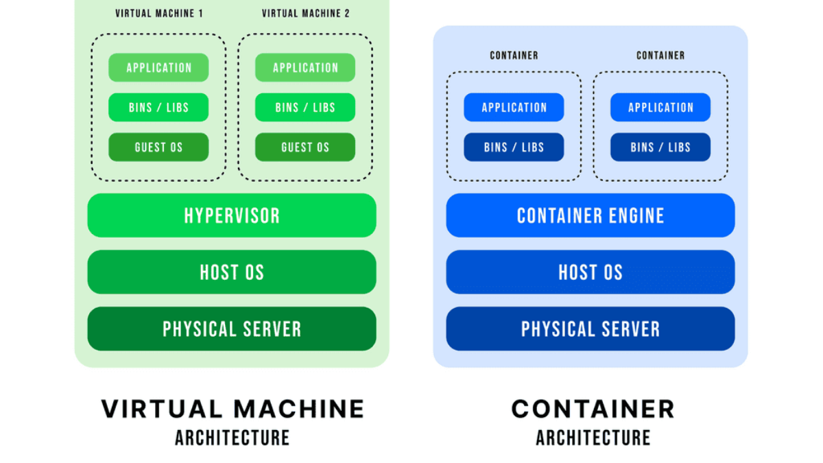
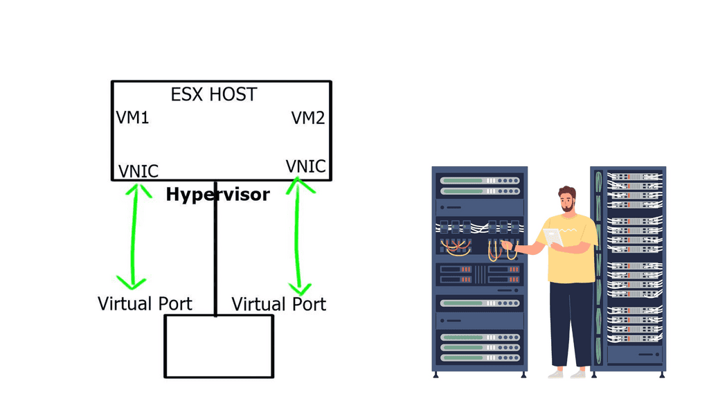
An operating system can run multiple operating systems on a single hardware host using a hypervisor, also known as a virtual machine manager. Operating systems use the host’s processor, memory, and other resources. Hypervisors control the host processor, memory, and other resources and allocate what each operating system needs. Hypervisors run guest operating systems or virtual machines on top of them.
Designed specifically for integration with VMware vSphere environments, the Cisco Nexus 1000V Series Switch runs Cisco NX-OS software. Enterprise-class performance, scalability, and scalability are delivered by VMware vSphere 2.0 across multiple platforms. Within the VMware ESX hypervisor, the Nexus 1000V runs. With the Cisco Nexus 1000V Series, you can take advantage of Cisco VN-Link server virtualization technology
• Policy-based virtual machine (VM) connectivity
• Mobile VM security
• Network policy
• Nondisruptive operational model for your server virtualization and networking teams
As with physical servers, virtual servers can be configured with the same network configuration, security policy, diagnostic tools, and operational models as physical servers. The Cisco Nexus 1000V Series is also compatible with VMware vSphere, vCenter, ESX, and ESXi.
A brief overview of the Nexus 1000V system
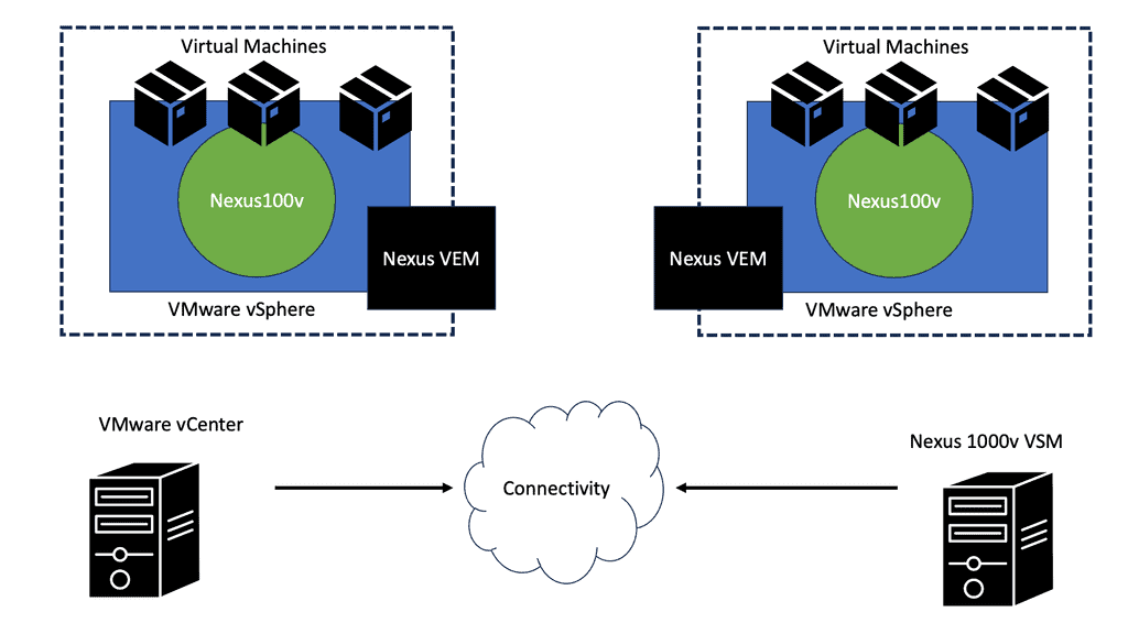
There are two primary components of the Cisco Nexus 1000V Series switch:
- VEM (Virtual Ethernet Module): Executes inside hypervisors
- VSM (External Virtual Supervisor Module): Manages VEMs
Nexus 1000v implements a generic concept of Cisco Distributed Virtual Switch (DVS). VMware ESX or ESXi executes the Cisco Nexus 1000V Virtual Ethernet Module (VEM). The VEM’s application programming interface (API) is VMware vNetwork Distributed Switch (vDS).
By integrating the API with VMware VMotion and Distributed Resource Scheduler (DRS), advanced networking capabilities can be provided to virtual machines. In the VEM, Layer 2 switching and advanced networking functions are performed based on configuration information from the VSM:
**Virtual routing and forwarding**
Virtual routing and forwarding form the basis of this stack. Firstly, network virtualization comes with two primary methods: 1) One too many and 2) Many to one. The “one too many” network virtualization method means you segment one physical network into multiple logical segments. Conversely, the “many to one” network virtualization method consolidates numerous physical devices into one logical entity. By definition, they seem to be opposites, but they fall under the same umbrella in network virtualization.
Before you proceed, you may find the following posts helpful:
Network virtualization
Before we get stuck in Cisco virtualization, let us address some basics. For example, if you have multiple virtual endpoints share a physical network. Still, different virtual endpoints belong to various customers, and the communication between these endpoints also needs to be isolated. In other words, the network is a resource, too, and network virtualization is the technology that enables the sharing of a standard physical network infrastructure.
Virtualization uses software to simulate traditional hardware platforms and create virtual software-based systems. For example, virtualization allows specialists to construct a single virtual network or partition a physical network into multiple virtual networks.
Cisco Switch Virtualization: Logical segmentation: One too many
We have one-to-many network virtualization for the Cisco switch virtualization design; a single physical network is logically segmented into multiple virtual networks. For example, each virtual network could correspond to a user group or a specific security function.
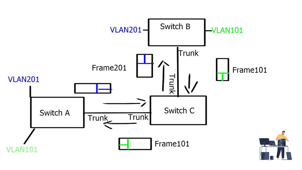
End-to-end path isolation requires the virtualization of networking devices and their interconnecting links. VLANs have been traditionally used, and hosts from one user group are mapped to a single VLAN. To extend the path across multiple switches at Layer 2, VLAN tagging (802.1Q) can carry VLAN information between switches. These VLAN trunks were created to transport multiple VLANs over a single Ethernet interface.
The diagram below displays two independent VLANs, VLAN201 and VLAN101. These VLANs can share one physical wire to provide L2 reachability between hosts connected to Switch B and Switch A via Switch C, but they remain separate entities.
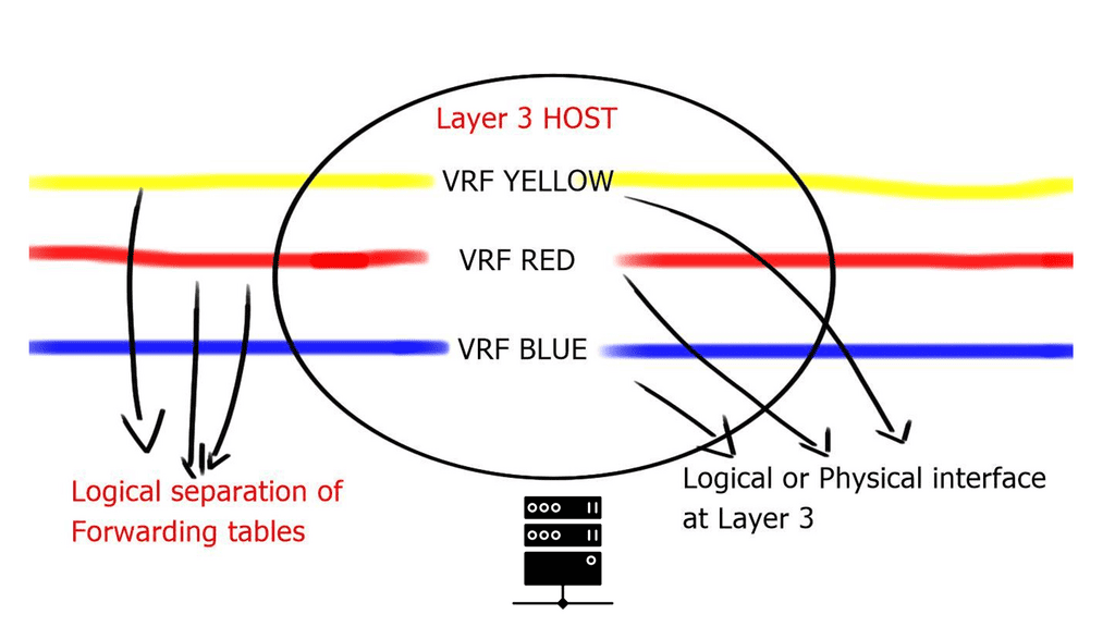
VLANs are sufficient for small Layer 2 segments. However, today’s networks will likely have a mix of Layer 2 and 3 routed networks. In this case, Layer 2 VLANs alone are insufficient because you must extend the Layer 2 isolation over a Layer 3 device. This can be achieved by using Virtual Routing and Forwarding ( VRF ), the next step in the Cisco switch virtualization. A virtual routing and forwarding instance logically carves a Layer 3 device into several isolated independent L3 devices. The virtual routing and forwarding configured locally cannot communicate directly.
The diagram below displays one physical Layer 3 router with three VRFs: VRF Yellow, VRF Red, and VRF Blue. These virtual routing and forwarding instances are completely separated; without explicit configuration, routes in one virtual routing and forwarding instance cannot be leaked to another.
Virtual Routing and Forwarding
The virtualization of the interconnecting links depends on how the virtual routers are connected. If they are physically ( directly ) connected, you could use a technology known as VRF-lite to separate traffic and 802.1Q to label the data plane. This is known as hop-by-hop virtualization.
However, it’s possible to run into scalability issues when the number of devices grows. This design is typically used when you connect virtual routing and forwarding back to back, i.e., no more than two devices.
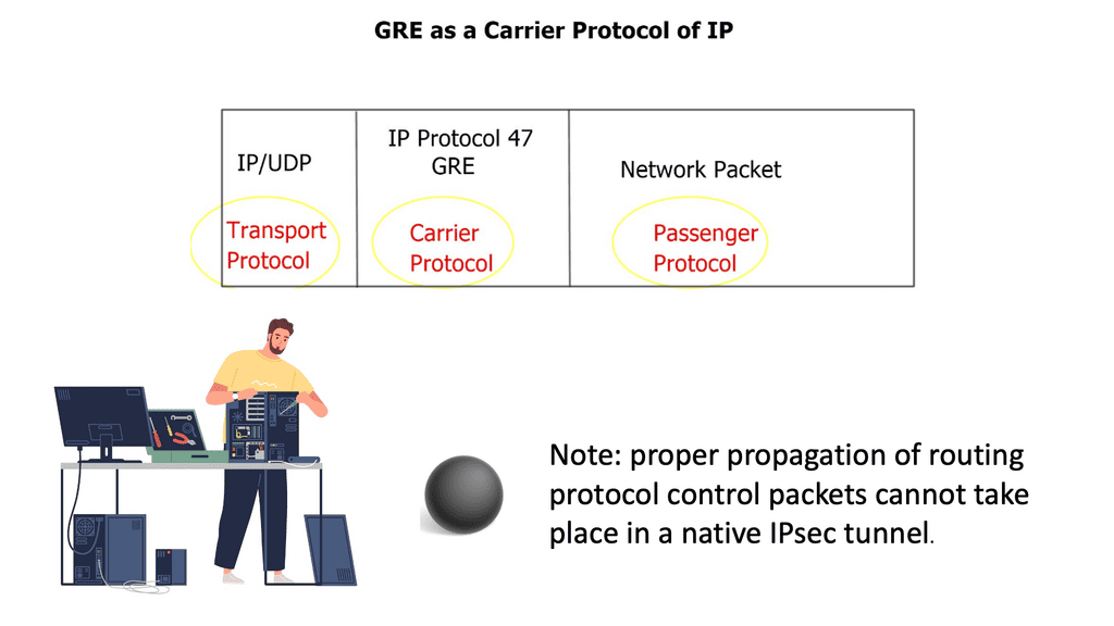
When the virtual routers are connected over multiple hops through an IP cloud, you can use generic routing encapsulation ( GRE ) or Multiprotocol Label Switching ( MPLS ) virtual private networks.
GRE is probably the simpler of the Layer 3 methods, and it can work over any IP core. GRE can encapsulate the contents and transport them over a network with the network unaware of the packet contents. Instead, the core will see the GRE header, virtualizing the network path.
Cisco Switch Virtualization: The additional overhead
When designing Cisco switch virtualization, you need to consider the additional overhead. There are a further 24 bytes overhead for the GRE header, so it may be the case that the forwarding router may break the datagram into two fragments, so the packet may not be larger than the outgoing interface MTU. To resolve the fragmentation issue, you can correctly configure MTU, MSS, and Path MTU parameters on the outgoing and intermediate routers.
The GRE standard is typically static. You only need to configure tunnel endpoints, and the tunnel will be up as long as you can reach those endpoints. However, recent designs can establish a dynamic GRE tunnel.
MPLS/VPN, on the other hand, is a different beast. It requires signaling to distribute labels and build an end-to-end Label Switched Path ( LSP ). The label distribution can be done with BGP+label, LDP, and RSVP. Unlike GRE tunnels, MPLS VPNs do not have to manage multiple point-to-point tunnels to provide a full mesh of connectivity. Instead, they are used for connectivity, and packets’ labels provide traffic separation.
Cisco switch virtualization: Many to one
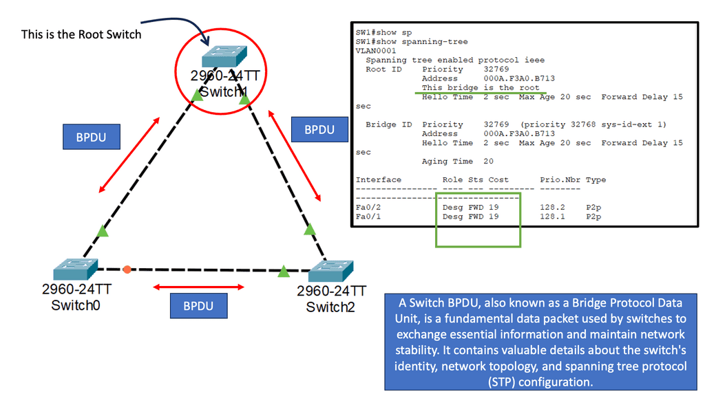
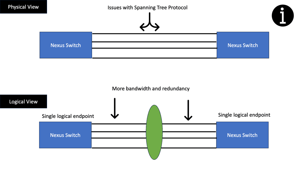
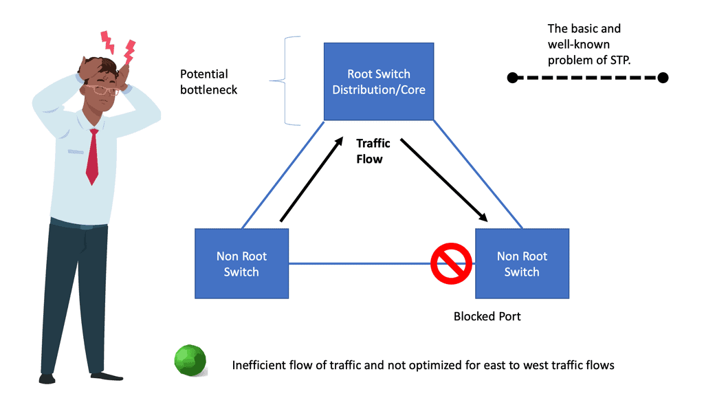
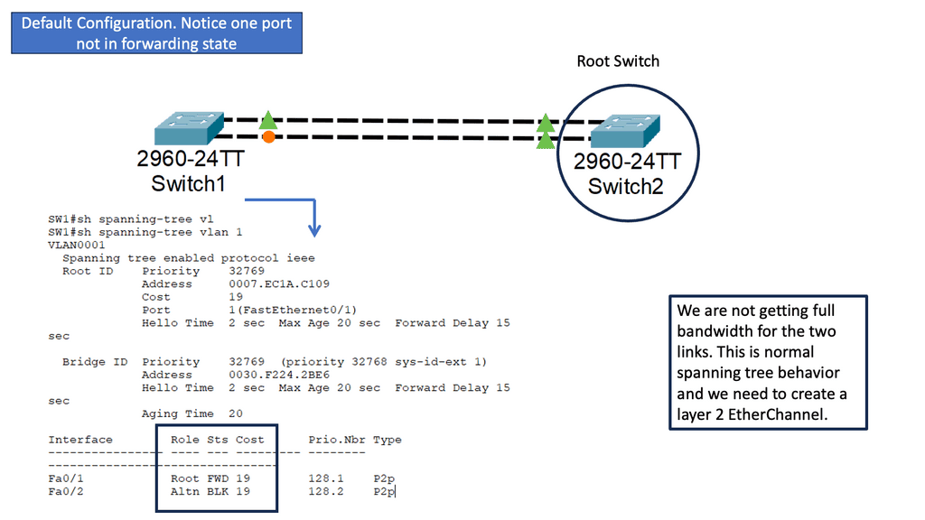
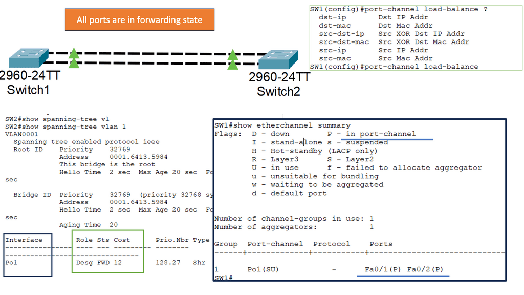
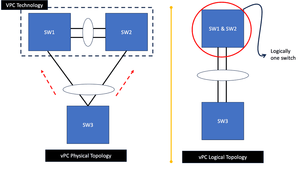
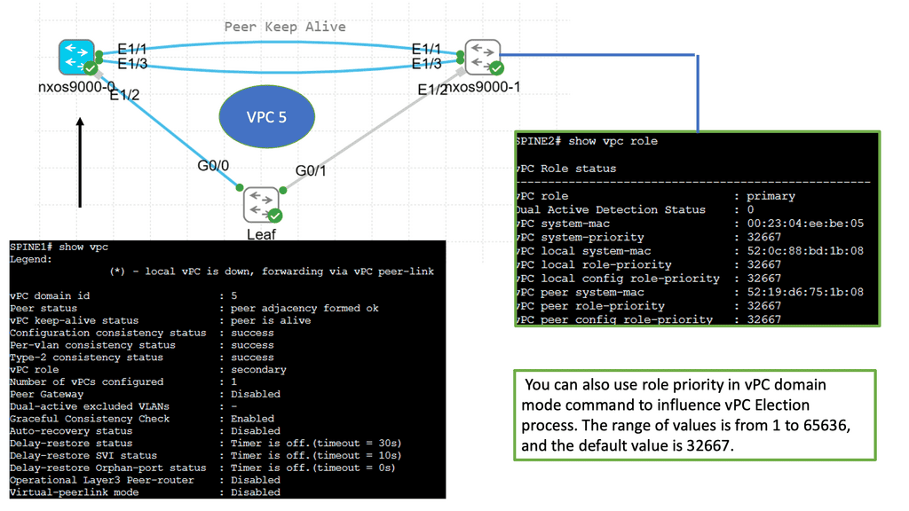
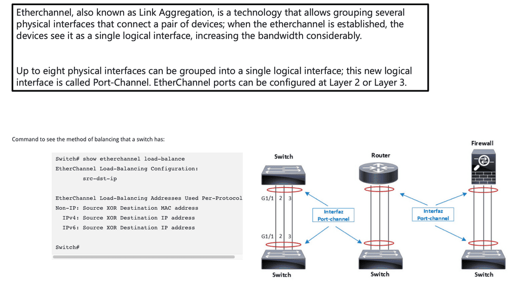
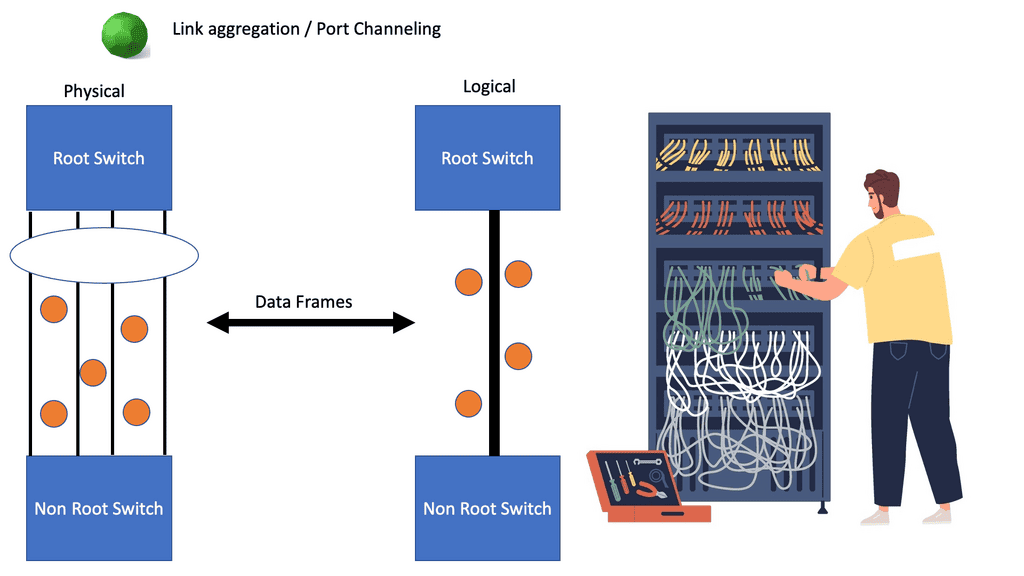
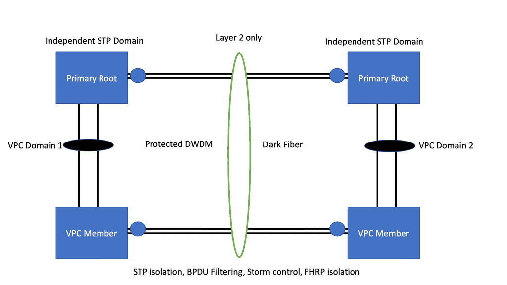
Many-to-one network consolidation refers to grouping two or more physical devices into one. Examples of this Cisco switch virtualization technology include a Virtual Switching System ( VSS ), Stackable switches, and Nexus VPC. Combining many physicals into one logical entity allows STP to view the logical group as one, allowing all ports to be active. By default, STP will block the redundant path.
Software-defined networking takes this concept further; it completely abstracts the entire network into a single virtual switch. The control and data planes are on the same device on traditional routers, yet they are decoupled with SDN. The control plan is now on a policy-driven controller, and the data plane is local on the OpenFlow-enabled switch.
Network Virtualization
Server and network virtualization presented the challenge of multiple VMs sharing a single network physical port, such as a network interface controller ( NIC ). The question then arises: how do I link multiple VMs to the same uplink? How do I provide path separation? Today’s networks need to virtualize the physical port and allow the configuration of policies per port.
NIC-per-VM design
One way to do this is to have a NIC-per-VM design where each VM is assigned a single physical NIC, and the NIC is not shared with any other VM. The hypervisor, aka virtualization layer, would be bypassed, and the VM would access the I/O device directly. This is known as VMDirectPath.
This direct path or pass-through can improve performance for hosts that utilize high-speed I/O devices, such as 10 Gigabit Ethernet. However, the lack of flexibility and the ability to move VMs offset higher performance benefits.
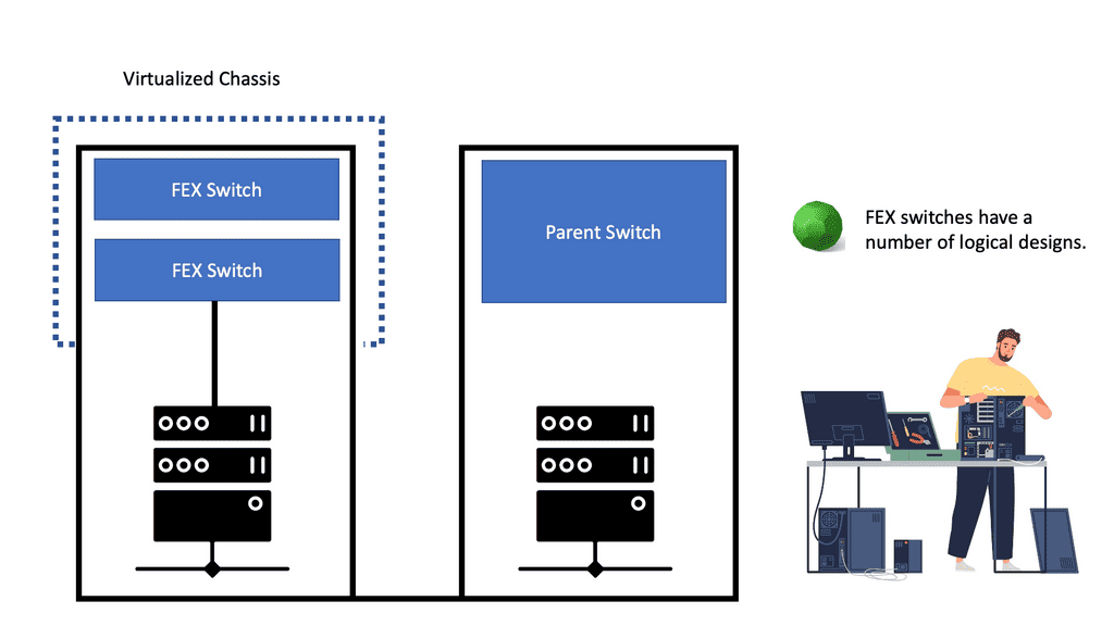
Virtual-NIC-per-VM in Cisco UCS (Adapter FEX)
Another way to do this is to create multiple logical NICs on the same physical NIC, such as Virtual-NIC-per-VM in Cisco UCS (Adapter FEX). These logical NICs are assigned directly to VMs, and traffic gets marked with a vNIC-specific tag on the hardware (VN-Tag/802.1ah).
The actual VN-Tag tagging is implemented in the server NICs so that you can clone the physical NIC in the server to multiple virtual NICs. This technology provides faster switching and enables you to apply a rich set of management features to local and remote traffic.
Software Virtual Switch
The third option is to implement a virtual software switch in the hypervisor. For example, VMware introduced virtual switching compatibility with its vSphere ( ESXi ) hypervisor, called vSphere Distributed Switch ( VDS ). Initially, they introduced a local L2 software switch, which was soon phased out due to a lack of distributed architecture.
Data physically moves between the servers through the external network, but the control plane abstracts this movement to look like one large distributed switch spanning multiple servers. This approach has a single management and configuration point, similar to stackable switches – one control plane with many physical data forwarding paths.
The data does not move through a parent partition but logically connects directly to the network interface through local vNICs associated with each VM.
Network virtualization and Nexus 1000v ( Nexus 1000 )
The VDS introduced by VMware lacked any good networking features, which led Cisco to introduce the Nexus 1000V software-based switch. The Nexus 1000v is a multi-cloud, multi-hypervisor, and multi-services distributed virtual switch. Its function is to enable communication between VMs.
**Nexus 1000 components: VEM and VSM**
The Nexus 1000v has two essential components:
- The Virtual Supervisor Module ( VSM )
- The Virtual Ethernet Module ( VEM ).
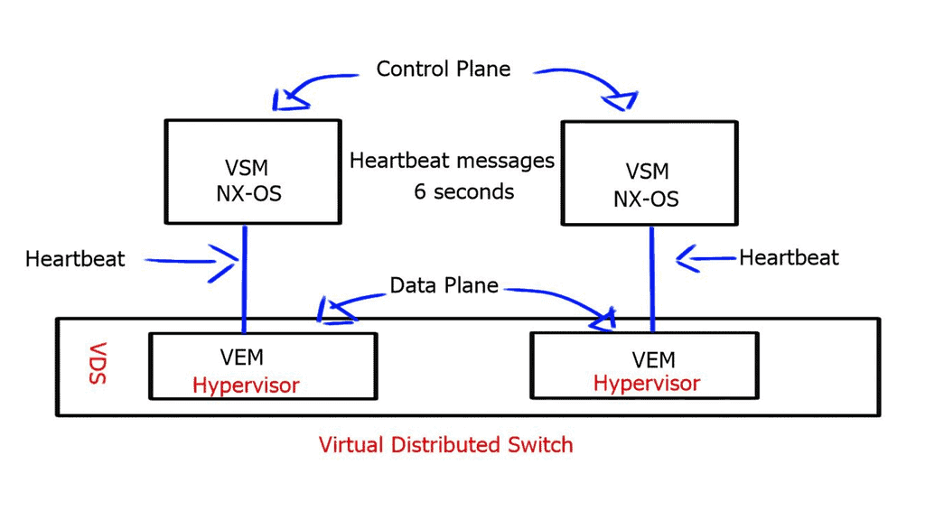
Compared to a physical switch, the VSM could be viewed as the supervisor, setting up the control plane functions for the data plane to forward efficiently, and the VEM as the physical line cards that do all the packet forwarding. The VEM is the software component that runs within the hypervisor kernel. It handles all VM traffic, including inter-VM frames and Ethernet traffic between a VM and external resources.
The VSM runs its NX-OS code and controls the control and management planes, which integrate into a cloud manager, such as a VMware vCenter. You can have two VSMs for redundancy. Both modules remain constantly synchronized with unicast VSM-to-VSM heartbeats to provide stateful failover in the event of an active VSM failure.
The two available communication options for VSM to VEM are:
- Layer 2 control mode: The VSM control interface shares the same VLAN with the VEM.
- Layer 3 control mode: The VEM and the VSM are in different IP subnets.
The VSM also uses heartbeat messages to detect a loss of connectivity between it and the VEM. However, the VEM does not depend on connectivity to the VSM to perform its data plane functions and will continue forwarding packets if the VSM fails.
With Layer 3 control mode, the heartbeat messages are encapsulated in a GRE envelope.
Nexus 1000 and VSM best practices
- L2 control is recommended for new installations.
- Use MAC pinning instead of LACP.
- Packet, Control, and Management in the same VLAN.
- Do not use VLAN 1 for Control and Packet.
- Use 2 x VSM for redundancy.
The max latency between VSM and VEM is ten milliseconds. Therefore, a VSM can be placed outside the data center if you have a high-quality DCI link, and the VEM can still be controlled.
Nexus 1000v InterCloud – Cisco switch virtualization
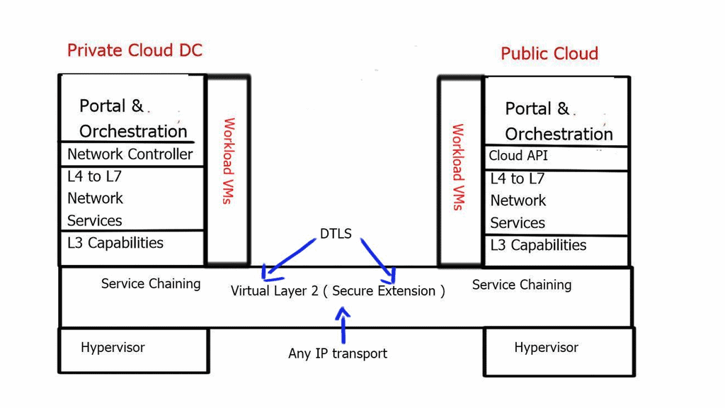
A vital element of the Nexus 1000 is its use case for hybrid cloud deployments and its ability to place workloads in private and public environments via a single pane of glass. In addition, the Nexus 1000v interCloud addresses the main challenges with hybrid cloud deployments, such as security concerns and control/visibility challenges within the public cloud.
The Nexus 1000 interCloud works with Cisco Prime Service Controller to create a secure L2 extension between the private data center and the public cloud.
This L2 extension is based on Datagram Transport Layer Security ( DTLS ) protocol and allows you to securely transfer VMs and Network services over a public IP backbone. DTLS derives the SSL protocol and provides communications privacy for datagram protocols, so all data in motion is cryptographically isolated and encrypted.
Nexus 1000v Hybrid Cloud Components
| Cisco Prime Network Service Controller for InterCloud ** | A VM that provides a single pane of glass to manage all functions of the inter clouds |
| InterCloud VSM | Manage port profiles for VMs in the InterCloud infrastructure |
| InterCloud Extender | Provides secure connectivity to the InterCloud Switch in the provider cloud. Install in the private data center. |
| InterCloud Switch | Virtual Machine in the provider data center has secure connectivity to the InterCloud Extender in the enterprise cloud and secure connectivity to the Virtual Machines in the provider cloud. |
| Cloud Virtual Machines | VMs in the public cloud running workloads. |
Prerequisites
| Port 80 | HTTP access from PNSC for AWS calls and communicating with InterCloud VMs in the provider cloud |
| Port 443 | HTTPS access from PNSC for AWS calls and communicating with InterCloud VMs in the provider cloud |
| Port 22 | SSH from PNSC to InterCloud VMs in the provider cloud |
| UDP 6644 | DTLS data tunnel |
| TCP 6644 | DTLS control tunnel |
VXLAN – Virtual Extensible LAN
The requirement for applications on demand has led to an increased number of required VLANs for cloud providers. The standard 12-bit identifier, which provided 4000 VLANs, proved to be a limiting factor in multi-tier, multi-tenant environments, and engineers started to run out of isolation options.
This has introduced a 24-bit VXLAN identifier, offering 16 million logical networks. Now, we can cross Layer 3 boundaries. The MAC in UDP encapsulation uses switch hashing to analyze UDP packets and efficiently distribute all packets in a port channel.
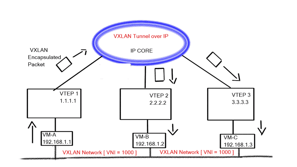
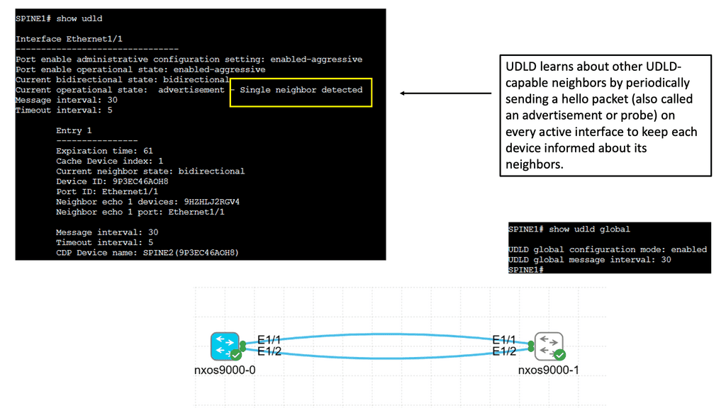
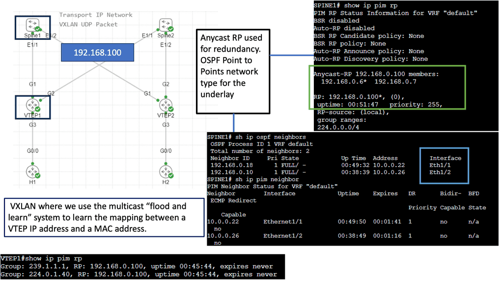
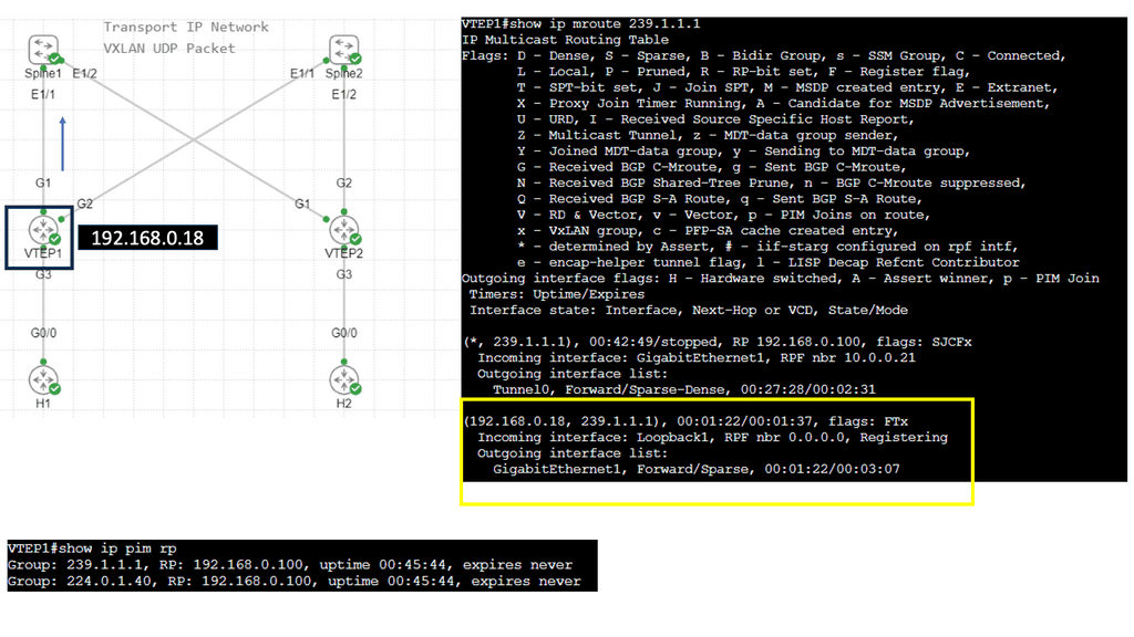
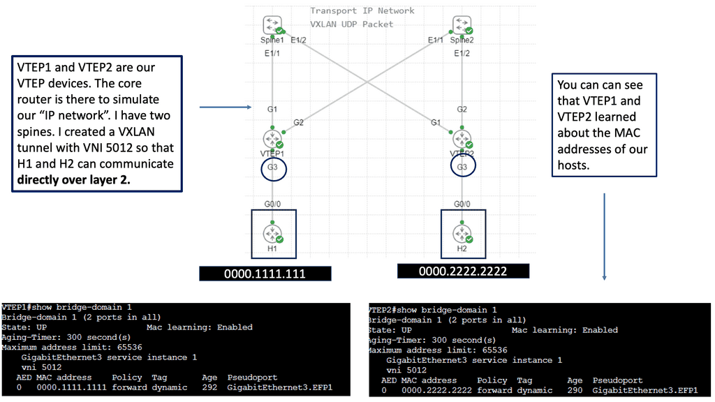
VXLAN works like a layer 2 bridge ( Flood and Learn ); the VEM learn does all the heavy lifting, learns all the VM source MAC and Host VXLAN IPs, and encapsulates the traffic according to the port profile to which the VM belongs. Broadcast, Multicast, and unknown unicast traffic are sent as Multicast.
At the same time, unicast traffic is encapsulated and shipped directly to the destination host’s VXLAN IP, aka destination VEM. Enhanced VXLAN offers VXLAN MAC distribution and ARP termination, making it more optional.
VXLAN Mode Packet Functions
| Packet | VXLAN(multicast mode) | Enhanced VXLAN(unicast mode) | Enhanced VXLANMAC Distribution | Enhanced VXLANARP Termination |
| Broadcast /Multicast | Multicast Encapsulation | Replication plus Unicast Encap | Replication plus Unicast Encap | Replication plus Unicast Encap |
| Unknown Unicast | Multicast Encapsulation | Replication plus Unicast Encap | Drop | Drop |
| Known Unicast | Unicast Encapsulation | Unicast Encap | Unicast Encap | Unicast Encap |
| ARP | Multicast Encapsulation | Replication plus Unicast Encap | Replication plus Unicast Encap | VEM ARP Reply |
vPath – Service chaining
Intelligent Policy-based traffic steering through multiple network services.
vPath allows you to intelligently traffic steer VM traffic to virtualized devices. It intercepts and redirects the initial traffic to the service node. Once the service node performs its policy function, the result is cached, and the local virtual switch treats the subsequent packets accordingly. In addition, it enables you to tie services together to push the VM through each service as required. Previously, if you wanted to tie services together in a data center, you needed to stitch the VLANs together, which was limited by design and scale.
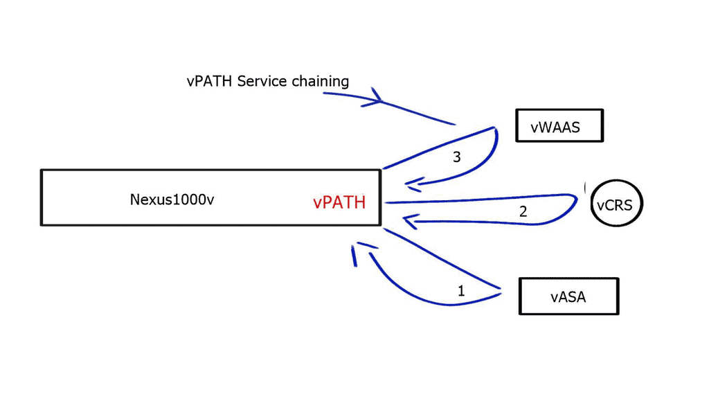
vPath 3.0 is now submitted to the IETF for standardization, allowing service chaining with vPath and non-vpath network services. It enables you to use vpath service chaining between multiple physical devices and supporting multiple hypervisors.
License Options
| Nexus 1000 Essential Edition | Nexus 1000 Advanced Edition |
| Full Layer-2 Feature Set | All Features of Essential Edition |
| Security, QoS Policies | VSG firewall |
| VXLAN virtual overlays | VXLAN Gateway |
| vPath enabled Virtual Services | TrustSec SGA |
| Full monitoring and management capabilities | A platform for other Cisco DC Extensions in the Future |
| Free | $695 per CPU MSRP |
Nexus 1000 features and benefits
| Switching | L2 Switching, 802.1Q Tagging, VLAN, Rate Limiting (TX), VXLAN IGMP Snooping, QoS Marking (COS & DSCP), Class-based WFQ |
| Security | Policy Mobility, Private VLANs w/ local PVLAN Enforcement Access Control Lists, Port Security, Cisco TrustSec Support Dynamic ARP inspection, IP Source Guard, DHCP Snooping |
| Network Services | Virtual Services Datapath (vPath) support for traffic steering & fast-path off-load[leveraged by Virtual Security Gateway (VSG), vWAAS, ASA1000V] |
| Provisioning | Port Profiles, Integration with vC, vCD, SCVMM*, BMC CLM Optimized NIC Teaming with Virtual Port Channel – Host Mode |
| Visibility | VM Migration Tracking, VC Plugin, NetFlow v.9 w/ NDE, CDP v.2 VM-Level Interface Statistics, vTrackerSPAN & ERSPAN (policy-based) |
| Management | Virtual Centre VM Provisioning, vCenter Plugin, Cisco LMS, DCNM Cisco CLI, Radius, TACACs, Syslog, SNMP (v.1, 2, 3) Hitless upgrade, SW Installer |
Advantages and disadvantages of the Nexus 1000
| Advantages | Disadvantages |
| The Standard edition is FREE; you can upgrade to an enhanced version when needed. | VEM and VSM internal communication is very sensitive to latency. Due to their chatty nature, they may not be good for inter-DC deployments. |
| Easy and Quick to deploy | VSM – VEM, VSM (active) – VSM (standby) heartbeat time of 6 seconds makes it sensitive to network failures and congestion. |
| It offers you many rich network features unavailable on other distributed software switches. | VEM over-dependency on VSM reduces resiliency. |
| Hypervisor agnostic | VSM is required for vSphere HA, FT, and VMotion to work. |
| Hybrid Cloud functionality |
**Closing Points on Cisco Nexus 1000v**
Virtual Ethernet Module (VEM):
The Nexus 1000v employs the Virtual Ethernet Module (VEM), which runs as a module inside the hypervisor. This allows for efficient and direct communication between VMs, bypassing the traditional reliance on the hypervisor networking stack.
Virtual Supervisor Module (VSM):
The Virtual Supervisor Module (VSM) serves as the control plane for the Nexus 1000v, providing centralized management and configuration. It enables network administrators to define policies, manage virtual ports, and monitor network traffic.
Policy-Based Virtual Network Management:
With the Nexus 1000v, administrators can define policies to manage virtual networks. These policies ensure consistent network configurations across multiple hosts, simplifying network management and reducing the risk of misconfigurations.
Advanced Security and Monitoring Capabilities:
The Nexus 1000v offers granular security controls, including access control lists (ACLs), port security, and dynamic host configuration protocol (DHCP) snooping. Additionally, it provides comprehensive visibility into network traffic, enabling administrators to monitor and troubleshoot network issues effectively.
Benefits of the Nexus 1000v:
Enhanced Network Performance:
By offloading network processing to the VEM, the Nexus 1000v minimizes the impact on the hypervisor, resulting in improved network performance and reduced latency.
Increased Scalability:
The distributed architecture of the Nexus 1000v allows for seamless scalability, ensuring that organizations can meet the growing demands of their virtualized environments.
Simplified Network Management:
With its policy-based approach, the Nexus 1000v simplifies network management tasks, enabling administrators to provision and manage virtual networks more efficiently.
Use Cases:
Data Centers:
The Nexus 1000v is particularly beneficial in data center environments where virtualization is prevalent. It provides a robust and scalable networking solution, ensuring optimal performance and security for virtualized workloads.
Cloud Service Providers:
Cloud service providers can leverage the Nexus 1000v to enhance their network virtualization capabilities, offering customers more flexibility and control over their virtual networks.
The Nexus 1000v is a powerful virtual network switch that provides advanced networking capabilities for virtualized environments. Its rich features, policy-based management approach, and seamless integration with VMware vSphere allow organizations to achieve enhanced network performance, scalability, and management efficiency. As virtualization continues to shape the future of data centers, the Nexus 1000v remains a valuable tool for optimizing virtual network infrastructures.