wan monitoring

WAN Monitoring

ENGINEERING GUIDE · WAN OBSERVABILITY

WAN Monitoring — From Link Health to Application Experience

WAN monitoring is no longer simply a question of whether a circuit or interface is up or down. Modern WANs combine Internet, MPLS, broadband, cellular, cloud connectivity and SD-WAN overlays, creating multiple paths that can change according to policy and real-time network conditions. Effective monitoring therefore needs to explain not only whether connectivity exists, but whether the path is delivering the expected application experience.

◉
The engineering problem A WAN can remain operational while performance is already failing. Increased latency, jitter, packet loss or congestion can create a brownout long before a circuit reports DOWN. Engineers therefore need correlated telemetry rather than a single health state.
01
OBSERVE

Collect telemetry from links, tunnels, routers, applications and cloud paths.

02
MEASURE

Quantify latency, jitter, packet loss, utilisation and availability against a baseline.

03
CORRELATE

Connect path conditions with routing, application behaviour and policy decisions.

04
ACT

Identify degradation, investigate the cause and determine whether traffic should move.

Engineering View

Monitor the path, not just the device

A router can be healthy while the service delivered through it is degraded. WAN monitoring must therefore combine infrastructure state with path-quality telemetry and application context. This becomes especially important with SD-WAN, where application traffic may be dynamically steered across several transports.

Latency How long does the path take?
Jitter How stable is packet delay?
Packet Loss Are packets being discarded?
Utilisation How much capacity is being consumed?
Investigation Question

Is the WAN actually healthy — or is it simply still reachable?

This distinction separates basic availability monitoring from engineering-grade observability. A healthy monitoring system should expose the evidence required to explain why application performance changes.

What This Guide Examines

From telemetry collection to WAN decision-making

The sections that follow examine WAN monitoring as an engineering workflow: how telemetry is collected, how performance signals are interpreted, how overlay and underlay conditions are correlated, and how brownouts can be investigated before they become complete outages. The goal is not simply to display more metrics, but to turn those metrics into operational evidence.

Latency
Jitter
Packet Loss
Utilisation
Telemetry
SD-WAN
Overlay
Underlay
Application Experience
Brownouts
WAN MONITORING LAB

WAN Monitoring Explorer

WAN health is not a single number. Engineers correlate latency, jitter, packet loss and utilisation to understand the quality of a WAN path.

WAN Path

TELEMETRY LIVE
◉ BRANCH R1 SOURCE
◎ CLOUD APP DESTINATION
Branch → WAN Edge → Cloud Application
42 ms Round Trip Time
0.2% Packet Loss
72% Utilisation

Signal Analysis

LATENCY SIGNAL

Latency measures path response time

Latency shows how long it takes traffic to travel across the monitored path and return. It is one of the fundamental indicators of WAN path quality.

What it tells you Whether the path is responding within the expected delay range.
What it doesn't tell you Latency alone cannot tell you whether delay is stable or whether packets are being dropped.

Example signal

RTT remains at 42 ms and is within the normal baseline.

Section 01 · SEE
OBSERVABILITY MODEL
A WAN Is a Path, Not Just a Device
Engineering-grade monitoring follows the dependency chain from infrastructure to transport, path quality and application experience.
DEVICEInterface & state
PATHLatency & loss
OVERLAYTunnel & policy
SERVICEUser experience
ENGINEERING EVIDENCE · SECTION 01

SEE — WAN Observability Architecture

Modern WAN monitoring is an observability chain rather than a single dashboard. A useful view must connect the physical and logical network to the path being used, the application consuming that path, and the policy controlling the decision. Without that relationship, engineers can see individual metrics without understanding what the metrics mean operationally.

Engineering principle
Telemetry must have context.

A latency measurement becomes significantly more useful when it is associated with a source, destination, path, interface, tunnel, application and expected baseline. The objective is not to collect the most telemetry — it is to build enough evidence to explain the behaviour of the WAN.

The WAN Observability Pipeline

01 · SOURCE Generate Evidence Routers, SD-WAN edges, endpoints, probes, applications and cloud services produce operational signals.
02 · COLLECT Capture Telemetry Polling, streaming telemetry, flow records, APIs and active probes bring observations into the monitoring system.
03 · NORMALIZE Build Context Timestamp, site, interface, tunnel, path and service information allow different telemetry sources to be compared.
04 · CORRELATE Join Signals Latency, jitter, loss, utilization, routing and application behaviour are examined together.
05 · DETECT Find Deviation Observed behaviour is compared with availability state, historical baselines and service thresholds.
06 · ACT Make a Decision Investigate, remediate, steer traffic or validate recovery using evidence rather than assumptions.

Four Views Must Agree

WAN visibility becomes much more powerful when multiple layers describe the same service path. A tunnel can remain established while its underlying transport is congested. A router can report healthy interfaces while an application experiences unacceptable delay. The monitoring architecture therefore needs to preserve the relationship between these layers.

01 · Underlay Physical Transport

Circuits, Internet links, MPLS, broadband, cellular and provider paths. This layer exposes availability, capacity and transport quality.

02 · Overlay Logical Connectivity

SD-WAN tunnels, VPNs and virtual paths. Overlay state explains which logical path is carrying traffic and which policy is controlling it.

03 · Application Service Experience

Application reachability and performance provide the user-facing outcome that infrastructure metrics alone cannot fully describe.

04 · Control Routing & Policy

Routing protocols, SD-WAN policy and path-selection logic determine how available paths are actually used.

Questions an Engineer Should Be Able to Answer

What path is the traffic actually using?
What changed from the normal baseline?
Which layer owns the degradation?
Is this a blackout or a brownout?

Evidence Sources

Different telemetry mechanisms answer different questions. They should be treated as complementary evidence rather than interchangeable data sources.

Example network evidence
show interfaces
show ip route
show ip sla statistics
show flow monitor
SD-WAN telemetry / API
The key distinction: reachability is not performance.

SNMP polling can expose device and interface state. Streaming telemetry can provide higher-frequency operational data. Flow telemetry describes traffic behaviour, while active probes measure the quality of a path between defined endpoints. The strongest WAN monitoring model combines these sources so that an apparently healthy link can still be investigated when application performance has degraded.

WAN OBSERVABILITY LAB

Trace the Evidence Pipeline

Select each stage to see what evidence is produced, how it gains context, and where an engineer can determine whether the WAN is actually healthy.

01 Sources Devices, flows, probes and applications
02 Collection Polling, streaming, flow and API data
03 Context Path, site, tunnel and service identity
04 Correlation Join network and application signals
05 Decision Detect, investigate and act
01 · Evidence Sources VISIBLE
Start with the observable system

WAN observability begins at the points where evidence can be generated. Device counters describe infrastructure state, flow records describe traffic behaviour, active probes measure path quality and application telemetry exposes service experience.

Infrastructure Interface / device state
Traffic Flow behaviour
Path Latency / jitter / loss
Service Application experience
Telemetry Inputs LIVE
Interface counters
SNMP / streaming
UP
Flow records
NetFlow / IPFIX
ACTIVE
Path probes
ICMP / IP SLA
ACTIVE
Application telemetry
API / synthetic
READY
Visibility completeness 86%
Evidence confidence High
Multiple telemetry sources describe the same WAN path. Correlation is therefore possible rather than relying on a single health state.
02
Measure the Path

Availability tells us whether traffic can reach its destination. Performance telemetry tells us whether the path is actually healthy.

LatencyPath delay
JitterDelay variation
Packet LossDelivery quality
UtilisationCapacity pressure
ENGINEERING EVIDENCE · SECTION 02

MEASURE — WAN Performance Signals

Once telemetry is available, the next engineering task is measurement. WAN health cannot be represented by a single UP or DOWN state because a path can remain reachable while latency, jitter, packet loss or congestion progressively degrade application performance. Effective monitoring therefore measures both availability and quality against an expected baseline.

Engineering principle
Measure deviation, not just absolute values.

A latency value of 50 ms may be perfectly normal for one path and highly abnormal for another. Monitoring becomes operationally useful when current behaviour is compared with the normal performance of that specific path, service and time period.

The Core WAN Signals

01 · DELAY Latency

Measures how long traffic takes to travel between defined endpoints. Increasing delay can indicate congestion, path changes or transport conditions even when reachability remains intact.

02 · VARIATION Jitter

Measures variation in packet delay. High or unstable jitter can affect real-time services such as voice, video and interactive applications.

03 · DELIVERY Packet Loss

Shows packets that fail to reach the destination. Even relatively small amounts of sustained loss can significantly affect application performance.

04 · CAPACITY Utilisation

Indicates how much available capacity is being consumed. High utilisation becomes especially important when it correlates with rising latency, queueing or packet loss.

Availability vs Performance

Availability answers whether the path is reachable. Performance asks whether the path is delivering the expected service quality. These are related but fundamentally different measurements.

Blackout Path unavailable
Brownout Path reachable, degraded
Healthy Within expected range
Unstable Repeated deviation

Build a Useful Baseline

A baseline represents normal behaviour for a path or service. It should account for recurring traffic patterns, business hours, application demand and known network conditions rather than treating every measurement as an independent event.

Latency Normal RTT range
Jitter Expected variation
Loss Normal loss level
Capacity Typical utilisation

From Signal to Operational Meaning

Individual metrics rarely provide the complete diagnosis. The engineering value comes from combining them and asking whether several signals changed together.

Latency rises Investigate path change, congestion, distance or transport conditions.
Loss + jitter rise Stronger evidence of path degradation than latency alone.
Utilisation + delay rise Correlation may indicate congestion or queueing pressure.
The engineering question is not “Is the link up?”

The more useful question is: “Is this path performing within the range expected for the service it carries?” That distinction is central to detecting WAN brownouts before they become complete outages.

WAN PERFORMANCE LAB

Measure the Path — Not Just the Link

Adjust the live performance signals and see how latency, jitter, packet loss and utilisation combine to describe the condition of the WAN path.

Observed WAN Path REACHABLE
Branch A 10.10.10.10
WAN Path DIA / SD-WAN
Cloud Service APP-SERVICE
Baseline performance · normal operating range
Latency 42 ms
10 ms 250 ms
Jitter 4 ms
0 ms 80 ms
Packet Loss 0.2%
0% 10%
Utilisation 42%
0% 100%
Path Assessment NORMAL
Healthy
Path quality is within the expected operating range.
Performance score 94 / 100
Engineering interpretation
All measured signals remain close to the established baseline.
Reference thresholds
Latency warning > 80 ms
Jitter warning > 15 ms
Loss warning > 1.0%
Utilisation warning > 75%
Engineering note: a path can remain reachable while several performance indicators move outside their normal range. That condition is a WAN brownout, not a simple availability failure.
Section 03 · CORRELATE
Turn Telemetry Into Evidence
A single metric describes a condition. Correlated telemetry explains whether that condition is actually affecting the service.
NETWORK
→
PATH
→
TRAFFIC
→
SERVICE
ENGINEERING EVIDENCE · SECTION 03

CORRELATE — Telemetry and Application Behaviour

Individual telemetry sources describe different parts of the WAN. Correlation connects those observations so that engineers can determine whether a change in network behaviour is actually affecting the service. This is the point where interface counters, flow records, path measurements, routing state and application experience become one operational picture.

Engineering principle
One signal indicates a condition. Multiple related signals provide evidence.

Rising utilisation alone does not prove that congestion is affecting an application. Rising utilisation combined with increased latency, packet loss and application response time creates a much stronger causal relationship.

The Correlation Chain

01 · NETWORK Observe Infrastructure

Interfaces, queues, routing state and device health establish what the network is doing.

02 · PATH Measure Quality

Active probes and telemetry expose latency, jitter, loss and path changes between defined endpoints.

03 · TRAFFIC Identify Behaviour

Flow data shows which applications, destinations and traffic classes are consuming the available path.

04 · SERVICE Confirm Experience

Application response, transaction success and user-facing performance establish whether the network condition matters to the service.

What Each Telemetry Source Tells You

Telemetry types should not be treated as interchangeable. Each provides evidence at a different layer of the system.

SNMP Periodic device and interface state, counters and utilisation.
Streaming Higher-frequency operational measurements pushed from network devices.
NetFlow / IPFIX Traffic-flow metadata showing who is communicating and how much traffic is involved.
Active probes Controlled measurements of reachability, latency, jitter and loss.

Application Context Completes the Picture

Network telemetry can show that a path changed. Application telemetry helps determine whether that change translated into a service impact.

Response time Shows whether application transactions are becoming slower.
Availability Confirms whether the service remains reachable from the user perspective.
Transactions Identifies failures that simple ICMP reachability may not reveal.
Experience Connects infrastructure behaviour to the actual service being consumed.

Correlation Turns Metrics into a Diagnosis

Consider a branch accessing a cloud application. A single metric may be ambiguous. The relationship between several measurements can make the operational condition much clearer.

Utilisation rises Indicates increased demand, but does not by itself prove application impact.
Latency + jitter rise Provides stronger evidence that the path itself is experiencing degradation.
Application slows Connects the network condition to an observable service consequence.

Correlated Observation

Interface utilisation 87%
Path latency 42 → 118 ms
Packet loss 0.2 → 2.1%
Application response +190 ms

Engineering Interpretation

Reachability AVAILABLE
Path quality DEGRADED
Application impact OBSERVED
Likely condition BROWNOUT
Correlation does not automatically prove causation — it creates the evidence needed to investigate it.

Engineers should still validate the path, routing state, transport conditions and application behaviour before declaring a root cause. The objective is to move from isolated metrics toward a defensible explanation of what changed, where it changed and what service was affected.

TELEMETRY CORRELATION LAB

Build the Evidence — One Signal at a Time

Select the observations available to the engineer. The correlation engine shows how confidence changes as network, path, traffic and application evidence are combined.

Available Evidence 4 / 8 selected
Interface utilisation
Infrastructure telemetry
87%
Path latency
Active measurement
118 ms
Packet loss
Active measurement
2.1%
Application response
Service telemetry
+190 ms
Jitter
Active measurement
31 ms
Routing state
Control-plane telemetry
UNCHANGED
Flow volume
NetFlow / IPFIX
+34%
Overlay tunnel
SD-WAN / VPN state
UP
Correlation Engine ANALYSING
Diagnostic confidence
HIGH
Multiple independent signals support the same operational condition.
Infrastructure condition DEGRADED
Path condition DEGRADED
Application impact OBSERVED
Likely diagnosis BROWNOUT
Engineering interpretation
The path remains reachable, but network quality and application performance have degraded together. This is stronger evidence of a WAN brownout than any single metric would provide.
Evidence coverage
Network
Path
Service
Section 04 · COMPARE
Overlay Health ≠ Underlay Health
UNDERLAY Transport path, provider network, interface quality and physical capacity.
DEPENDS ON
OVERLAY Logical tunnel, routing policy and application-facing connectivity.
Engineering Evidence · Section 04

COMPARE — Overlay vs Underlay

WAN monitoring becomes more useful when engineers separate the logical path from the physical or transport path underneath it. An SD-WAN tunnel can remain established while the Internet, MPLS, broadband or cellular transport carrying that tunnel is experiencing degradation.

Visibility principle A healthy overlay does not automatically prove a healthy underlay. Monitoring both layers allows engineers to determine where the degradation is actually occurring.
Underlay
The transport path

Internet, MPLS, broadband, LTE/5G or other transport connectivity. Engineers monitor reachability, latency, jitter, packet loss, utilisation and interface health.

Overlay
The logical service path

IPsec tunnels, SD-WAN paths, VPNs and policy-controlled logical connections. The overlay provides the service abstraction used to carry application traffic across the available transports.

Where the monitoring layers meet
Underlay Internet / MPLS / DIA
→
Overlay VPN / SD-WAN tunnel
→
Application SaaS / Cloud / Data Centre
Observation
Layer
Engineering interpretation
Interface utilisation rises
Underlay
Transport capacity may be approaching a constraint.
IPsec tunnel remains UP
Overlay
Logical connectivity exists, but this does not prove path quality.
RTT increases across probe
Underlay / Path
Transport performance has changed and should be correlated with the overlay.
Application response slows
Service
Confirms that the network condition has potential user-facing impact.
Engineering rule: monitor the dependency chain.

When an overlay tunnel reports UP but users report poor performance, do not treat the tunnel state as proof that the WAN is healthy. Compare overlay state, underlay path measurements and application behaviour. The objective is to identify the first layer where the expected performance relationship breaks down.

Interactive Engineering Lab · WAN Monitoring

Overlay vs Underlay — Find the Hidden Degradation

Switch monitoring views to see why tunnel state alone is not enough. The overlay can remain established while the transport path underneath it develops latency, jitter or packet loss.

Logical + Transport Path
Tunnel Established
Overlay · Logical Service Path
Underlay · Transport Path
Branch A WAN Edge
Internet / MPLS Underlay Transport
Branch B WAN Edge
Application Cloud / SaaS
Layer Inspection
Current View
Combined Evidence
Overlay tunnel ESTABLISHED
Route state INSTALLED
Underlay RTT 112 ms
Packet loss 1.8%
Application RTT +160 ms
The overlay is healthy from a control-state perspective, but the transport evidence indicates degradation underneath it.
Overlay Evidence Tunnel UP
Underlay Evidence Path DEGRADED
Service Evidence Experience IMPACTED
Section 05 · INVESTIGATE
The Brownout Problem
A WAN can remain reachable while latency, jitter and packet loss deteriorate enough to affect applications. That is a performance failure even though the circuit is still technically UP.
HARD FAILURE Connectivity disappears.
BROWNOUT Connectivity survives. Performance degrades.
Engineering Evidence · Section 05

INVESTIGATE — WAN Brownout

A WAN brownout occurs when connectivity remains available but the quality of service has deteriorated enough to affect applications. Unlike a hard outage, the interface, tunnel and routing system may continue to report healthy states while users experience slower or unreliable service.

Failure investigation principle Do not wait for the circuit to go DOWN. Detect the performance relationship breaking before availability is lost.
Hard Failure
Connectivity disappears

Interface or path becomes unavailable, sessions fail and routing may reconverge. The failure is usually visible through availability monitoring.

Brownout
Connectivity survives, performance fails

The path remains reachable while latency, jitter, packet loss or congestion increases. Application performance becomes the critical evidence.

Brownout Evidence Snapshot
Interface UP Availability intact
Latency 168 ms Baseline 42 ms
Jitter 31 ms Baseline 4 ms
Packet Loss 3.4% Baseline 0.2%
01
Confirm Availability

Verify interfaces, tunnels and routing remain operational.

02
Compare Baseline

Compare current latency, jitter, loss and utilisation with normal operating behaviour.

03
Correlate Impact

Determine whether degraded path conditions coincide with application or traffic-performance changes.

04
Validate Cause

Check routing, queues, capacity and alternate paths before declaring the root cause.

Likely Condition: WAN Brownout

The evidence indicates that connectivity remains available but path quality has moved significantly away from its baseline. Elevated latency, jitter and packet loss provide stronger evidence of degradation than interface state alone.

Investigation Checks
✓ Interface and tunnel remain operational
✓ Performance metrics exceed baseline
✓ Application impact is observable
✓ Alternate path should be evaluated
Engineering principle: investigate the first meaningful deviation.

The final application symptom may be several steps removed from the original network condition. Start with the earliest measurable deviation from baseline, then correlate forward through the path, overlay, routing and application layers. This produces a defensible diagnosis rather than simply identifying the last visible symptom.

Interactive Incident Investigation · WAN Monitoring

WAN Brownout Investigation Lab

A simulated WAN incident is degrading application performance while connectivity remains available. Collect the right evidence, correlate the signals and identify the condition before declaring the root cause.

01 · Availability
02 · Baseline
03 · Impact
04 · Diagnosis
Evidence Collection · Click observations to collect them
✓
Availability UP WAN interface and transport remain reachable.
✓
Overlay ESTABLISHED Logical WAN tunnel remains operational.
✓
Latency 168 ms Baseline: 42 ms.
✓
Jitter 31 ms Baseline: 4 ms.
✓
Packet Loss 3.4% Baseline: 0.2%.
✓
Application +240 ms Transaction response time increase.
[00:00] Investigation started. [00:01] Select evidence to begin correlation.
Diagnostic Engine
Evidence Confidence
0%
Current Condition INSUFFICIENT EVIDENCE

Collect availability, path-quality and application evidence before reaching a conclusion.

Investigation Principle Availability ≠ Performance

A reachable path can still violate application performance expectations.

Diagnosis: WAN BROWNOUT Interface and tunnel availability remain intact, while latency, jitter, packet loss and application response have all moved away from baseline. The evidence supports a performance degradation rather than a hard connectivity outage.
Section 06 · OPTIMIZE
From Monitoring to Path Decisions
Once path quality is measured and correlated with application requirements, monitoring can become an input to operational path-selection decisions.
MEASURE Path quality
CLASSIFY Application need
EVALUATE Policy + evidence
STEER Eligible traffic
Engineering Evidence · Section 06

OPTIMIZE — Performance-Based Path Selection

Monitoring becomes operationally valuable when the collected evidence can influence path selection. Modern WANs may provide multiple transports, allowing traffic to be steered according to application requirements, policy and measured path quality rather than simply selecting the path that is administratively preferred.

Engineering principle The best WAN path is not necessarily the path with the lowest cost. It is the path that satisfies the application's performance and policy requirements at the time traffic is evaluated.
01 · Measure
Know the path condition

Collect latency, jitter, packet loss, utilisation and availability measurements for each candidate transport.

02 · Classify
Understand the application

Voice, interactive SaaS, bulk transfer and general web traffic can have very different performance requirements.

03 · Decide
Apply policy and evidence

Select or steer traffic toward a path that satisfies the relevant SLA while respecting operational policy and available capacity.

Example Candidate Paths
Path
Latency
Jitter
Loss
Engineering State
MPLS
38 ms
4 ms
0.1%
Strong candidate for real-time traffic
DIA
46 ms
7 ms
0.3%
Suitable alternative for most applications
LTE
82 ms
19 ms
1.4%
Useful resilience path, but weaker SLA
01
Define the SLA

Establish acceptable latency, jitter, loss and availability for the application or traffic class.

02
Measure Candidates

Compare live path telemetry rather than relying only on static circuit characteristics.

03
Evaluate Policy

Combine path quality with business, security and routing policy before selecting a path.

04
Steer Traffic

Move eligible traffic toward a suitable path when the platform supports policy-based performance steering.

From monitoring to closed-loop WAN operations.

The progression is straightforward: observe the paths, measure their behaviour, understand the application's requirements, evaluate policy and then make a path-selection decision. Monitoring therefore becomes more than a dashboard function — it becomes an input into how the WAN operates.

Interactive Decision Lab · WAN Monitoring

Performance-Based Path Selection

Select an application profile and compare the available WAN paths. The decision engine evaluates measured path quality against the application's performance requirements rather than choosing purely from static administrative preference.

Application Profile
Live Candidate Paths · Click a path to inspect
MPLS
Private Transport
Latency 38 ms
Jitter 4 ms
Loss 0.1%
Utilisation 72%
Healthy
DIA
Internet Transport
Latency 46 ms
Jitter 7 ms
Loss 0.3%
Utilisation 48%
Healthy
LTE / 5G
Wireless Resilience
Latency 82 ms
Jitter 19 ms
Loss 1.4%
Utilisation 31%
Degraded
Decision Engine
Application Requirement
Low Latency + Low Jitter
Recommended Path
MPLS
Path Scores
MPLS
0
DIA
0
LTE
0
Engineering Decision MPLS currently provides the strongest measured characteristics for real-time traffic. DIA remains a viable alternative, while LTE/5G is better treated as a resilience path under the current measurements.
WAN MONITORING LAB

Overlay vs Underlay Visibility

An SD-WAN tunnel can remain healthy while the physical network underneath it is experiencing congestion, loss or delay. Effective WAN monitoring needs visibility into both layers.

WAN Path Model

BOTH LAYERS VISIBLE
SD-WAN Overlay Is the tunnel healthy?
◉ BRANCH EDGE
◎ CLOUD EDGE
WAN Underlay What is happening underneath?
ISP / MPLS Transport
INTERNET Transport

Monitoring View

COMBINED VISIBILITY

Monitor both the tunnel and the transport

Overlay telemetry tells you whether the SD-WAN service is established and forwarding traffic. Underlay telemetry helps explain the quality of the physical or provider path carrying that traffic.

✓
Overlay Tunnel established and forwarding traffic.
✓
Underlay Transport path is currently within baseline.
→
Investigation Correlate both layers when application performance changes.

WAN Monitoring Principle

A healthy overlay does not automatically mean the underlying transport is healthy. Monitoring both layers helps distinguish tunnel problems from transport problems.

WAN MONITORING INVESTIGATION

WAN Brownout Investigation

A WAN can be technically "up" while application performance is degrading. Investigate the evidence and determine what is happening to the path.

INCIDENT

Application performance has degraded, but both WAN links are UP.

No interface is down and the SD-WAN tunnel remains established. Examine the telemetry before deciding what is causing the problem.

Investigation Evidence

INVESTIGATE

Compare the current measurements with the established baseline. Look for correlated changes rather than relying on link state alone.

LINK STATE UP
UP Expected: UP

Physical interface remains operational.

RTT DEGRADED
168 ms Baseline: 42 ms

Round-trip delay has increased significantly.

JITTER DEGRADED
31 ms Baseline: 4 ms

Packet delay has become significantly less stable.

PACKET LOSS DEGRADED
3.4% Baseline: 0.2%

Packet delivery has deteriorated.

UTILISATION HIGH
87% Baseline: 72%

Link consumption has increased substantially.

SD-WAN TUNNEL ESTABLISHED
UP Expected: UP

Logical overlay remains established.

Performance timeline

Normal
42 ms / 0.2%
Degradation begins
RTT rises
Current
168 ms / 3.4%

Engineer's Diagnosis

GUIDED INVESTIGATION

What is the most likely network condition?

The links and overlay tunnel remain operational. Focus on the combination of performance signals rather than the binary UP/DOWN state.

Investigation result

Select an answer and check the evidence.

The Correlation Chain

Link State The interface is still UP.
→
Path Quality RTT, jitter and loss have increased.
→
Capacity Utilisation has increased.
→
Application User experience has degraded.
```
☕
Support Network Insight
Help support independent engineering guides, interactive networking tools, and future learning labs.
Support Network Insight ```
network overlays

WAN Virtualization

WAN Virtualization

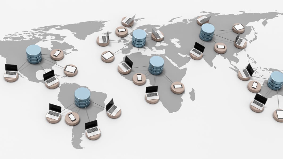
In today's fast-paced digital world, seamless connectivity is the key to success for businesses of all sizes. WAN (Wide Area Network) virtualization has emerged as a game-changing technology, revolutionizing the way organizations connect their geographically dispersed branches and remote employees. In this blog post, we will explore the concept of WAN virtualization, its benefits, implementation considerations, and its potential impact on businesses.

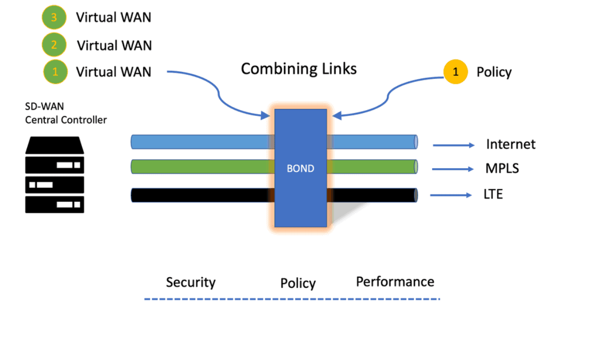
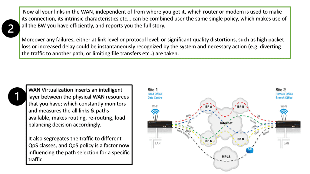
WAN virtualization is a technology that abstracts the physical network infrastructure, allowing multiple logical networks to operate independently over a shared physical infrastructure. It enables organizations to combine various types of connectivity, such as MPLS, broadband, and cellular, into a single virtual network. By doing so, WAN virtualization enhances network performance, scalability, and flexibility.

Increased Flexibility and Scalability: WAN virtualization allows businesses to scale their network resources on-demand, facilitating seamless expansion or contraction based on their requirements. It provides flexibility to dynamically allocate bandwidth, prioritize critical applications, and adapt to changing network conditions.

Improved Performance and Reliability: By leveraging intelligent traffic management techniques and load balancing algorithms, WAN virtualization optimizes network performance. It intelligently routes traffic across multiple network paths, avoiding congestion and reducing latency. Additionally, it enables automatic failover and redundancy, ensuring high network availability.

Simplified Network Management: Traditional WAN architectures often involve complex configurations and manual provisioning. WAN virtualization simplifies network management by centralizing control and automating tasks. Administrators can easily set policies, monitor network performance, and make changes from a single management interface, saving time and reducing human errors.

Multi-Site Connectivity: For organizations with multiple remote sites, WAN virtualization offers a cost-effective solution. It enables seamless connectivity between sites, allowing efficient data transfer, collaboration, and resource sharing. With centralized management, network administrators can ensure consistent policies and security across all sites. Cloud Connectivity:

As more businesses adopt cloud-based applications and services, WAN virtualization becomes an essential component. It provides reliable and secure connectivity between on-premises infrastructure and public or private cloud environments. By prioritizing critical cloud traffic and optimizing routing, WAN virtualization ensures optimal performance for cloud-based applications.

Highlights: WAN Virtualization

### The Basics of WAN

A WAN is a telecommunications network that extends over a large geographical area. It is designed to connect devices and networks across long distances, using various communication links such as leased lines, satellite links, or the internet. The primary purpose of a WAN is to facilitate the sharing of resources and information across locations, making it a vital component of modern business infrastructure. WANs can be either private, connecting specific networks of an organization, or public, utilizing the internet for broader connectivity.

### The Role of Virtualization in WAN

Virtualization has revolutionized the way WANs operate, offering enhanced flexibility, efficiency, and scalability. By decoupling network functions from physical hardware, virtualization allows for the creation of virtual networks that can be easily managed and adjusted to meet organizational needs. This approach reduces the dependency on physical infrastructure, leading to cost savings and improved resource utilization. Virtualized WANs can dynamically allocate bandwidth, prioritize traffic, and ensure optimal performance, making them an attractive solution for businesses seeking agility and resilience.

Separating: Control and Data Plane:

1: – WAN virtualization can be defined as the abstraction of physical network resources into virtual entities, allowing for more flexible and efficient network management. By separating the control plane from the data plane, WAN virtualization enables the centralized management and orchestration of network resources, regardless of their physical locations. This simplifies network administration and paves the way for enhanced scalability and agility.

2: – WAN virtualization optimizes network performance by intelligently routing traffic and dynamically adjusting network resources based on real-time conditions. This ensures that critical applications receive the necessary bandwidth and quality of service, resulting in improved user experience and productivity.

3: – By leveraging WAN virtualization, organizations can reduce their reliance on expensive dedicated circuits and hardware appliances. Instead, they can leverage existing network infrastructure and utilize cost-effective internet connections without compromising security or performance. This significantly lowers operational costs and capital expenditures.

4: – Traditional WAN architectures often struggle to meet modern businesses’ evolving needs. WAN virtualization solves this challenge by providing a scalable and flexible network infrastructure. With virtual overlays, organizations can rapidly deploy and scale their network resources as needed, empowering them to adapt quickly to changing business requirements.

**Implementing WAN Virtualization**

Successful implementation of WAN virtualization requires careful planning and execution. Start by assessing your current network infrastructure and identifying areas for improvement. Choose a virtualization solution that aligns with your organization’s specific needs and budget. Consider leveraging software-defined WAN (SD-WAN) technologies to simplify the deployment process and enhance overall network performance.

There are several popular techniques for implementing WAN virtualization, each with its unique characteristics and use cases. Let’s explore a few of them:

a. MPLS (Multi-Protocol Label Switching): MPLS is a widely used technique that leverages labels to direct network traffic efficiently. It provides reliable and secure connectivity, making it suitable for businesses requiring stringent service level agreements (SLAs).

b. SD-WAN (Software-Defined Wide Area Network): SD-WAN is a revolutionary technology that abstracts and centralizes the network control plane in software. It offers dynamic path selection, traffic prioritization, and simplified network management, making it ideal for organizations with multiple branch locations.

c. VPLS (Virtual Private LAN Service): VPLS extends the functionality of Ethernet-based LANs over a wide area network. It creates a virtual bridge between geographically dispersed sites, enabling seamless communication as if they were part of the same local network.

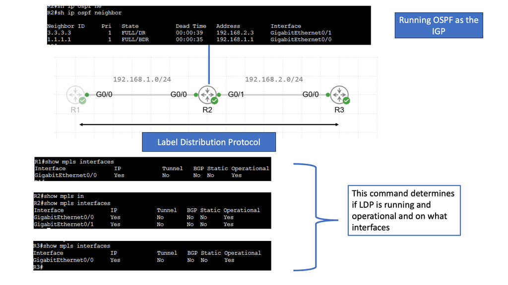
Example Technology: MPLS & LDP

**The Mechanics of MPLS: How It Works**

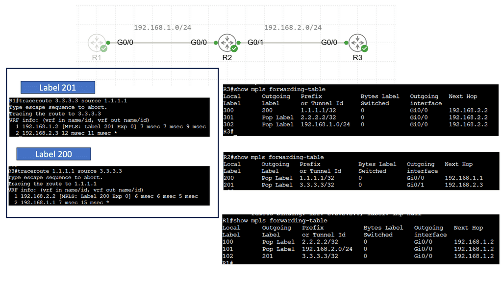
MPLS operates by assigning labels to data packets at the network’s entry point—an MPLS-enabled router. These labels determine the path the packet will take through the network, enabling quick and efficient routing. Each router along the path uses the label to make forwarding decisions, eliminating the need for complex table lookups. This not only accelerates data transmission but also allows network administrators to predefine optimal paths for different types of traffic, enhancing network performance and reliability.

**Exploring LDP: The Glue of MPLS Systems**

The Label Distribution Protocol (LDP) is crucial for the functioning of MPLS networks. LDP is responsible for the distribution of labels between routers, ensuring that each understands how to handle the labeled packets appropriately. When routers communicate using LDP, they exchange label information, which helps in building a label-switched path (LSP). This process involves the negotiation of label values and the establishment of the end-to-end path that data packets will traverse, making LDP the unsung hero that ensures seamless and effective MPLS operation.

**Benefits of MPLS and LDP in Modern Networks**

MPLS and LDP together offer a range of benefits that make them indispensable in contemporary networking. They provide a scalable solution that supports a wide array of services, including VPNs, traffic engineering, and quality of service (QoS). This versatility makes it easier for network operators to manage and optimize traffic, leading to improved bandwidth utilization and reduced latency. Additionally, MPLS networks are inherently more secure, as the label-switching mechanism makes it difficult for unauthorized users to intercept or tamper with data.
Overcoming Potential Challenges

While WAN virtualization offers numerous benefits, it also presents certain challenges. Security is a top concern, as virtualized networks can introduce new vulnerabilities. It’s essential to implement robust security measures, such as encryption and access controls, to protect your virtualized WAN. Additionally, ensure your IT team is adequately trained to manage and monitor the virtual network environment effectively.

**Section 1: The Complexity of Network Integration**

One of the primary challenges in WAN virtualization is integrating new virtualized solutions with existing network infrastructures. This task often involves dealing with legacy systems that may not easily adapt to virtualized environments. Organizations need to ensure compatibility and seamless operation across all network components. To address this complexity, businesses can employ network abstraction techniques and use software-defined networking (SDN) tools that offer greater control and flexibility, allowing for a smoother integration process.

**Section 2: Security Concerns in Virtualized Environments**

Security remains a critical concern in any network architecture, and virtualization adds another layer of complexity. Virtual environments can introduce vulnerabilities if not properly managed. The key to overcoming these security challenges lies in implementing robust security protocols and practices. Utilizing encryption, firewalls, and regular security audits can help safeguard the network. Additionally, leveraging network segmentation and zero-trust models can significantly enhance the security of virtualized WANs.

**Section 3: Managing Performance and Reliability**

Ensuring consistent performance and reliability in a virtualized WAN is another significant challenge. Virtualization can sometimes lead to latency and bandwidth issues, affecting the overall user experience. To mitigate these issues, organizations should focus on traffic optimization techniques and quality of service (QoS) management. Implementing dynamic path selection and traffic prioritization can ensure that mission-critical applications receive the necessary bandwidth and performance, maintaining high levels of reliability across the network.

**Section 4: Cost Implications and ROI**

While WAN virtualization can lead to cost savings in the long run, the initial investment and transition can be costly. Organizations must carefully consider the cost implications and potential return on investment (ROI) when adopting virtualized solutions. Conducting thorough cost-benefit analyses and pilot testing can provide valuable insights into the financial viability of virtualization projects. By aligning virtualization strategies with business goals, companies can maximize ROI and achieve sustainable growth.

WAN Virtualisation & SD-WAN Cloud Hub

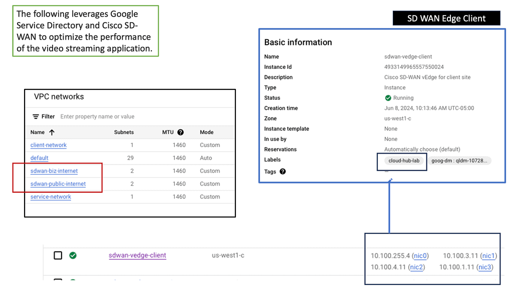
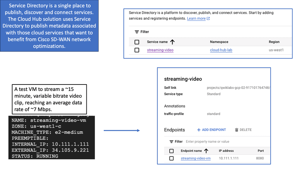
SD-WAN Cloud Hub is a cutting-edge networking solution that combines the power of software-defined wide area networking (SD-WAN) with the scalability and reliability of cloud services. It acts as a centralized hub, enabling organizations to connect their branch offices, data centers, and cloud resources in a secure and efficient manner. By leveraging SD-WAN Cloud Hub, businesses can simplify their network architecture, improve application performance, and reduce costs.

Google Cloud needs no introduction. With its robust infrastructure, comprehensive suite of services, and global reach, it has become a preferred choice for businesses across industries. From compute and storage to AI and analytics, Google Cloud offers a wide range of solutions that empower organizations to innovate and scale. By integrating SD-WAN Cloud Hub with Google Cloud, businesses can unlock unparalleled benefits and take their network connectivity to new heights.
Understanding SD-WAN

SD-WAN is a cutting-edge networking technology that utilizes software-defined principles to manage and optimize network connections intelligently. Unlike traditional WAN, which relies on costly and inflexible hardware, SD-WAN leverages software-based solutions to streamline network management, improve performance, and enhance security.

Key Benefits of SD-WAN

a) Enhanced Performance: SD-WAN intelligently routes traffic across multiple network paths, ensuring optimal performance and reduced latency. This results in faster data transfers and improved user experience.

b) Cost Efficiency: With SD-WAN, businesses can leverage affordable broadband connections rather than relying solely on expensive MPLS (Multiprotocol Label Switching) links. This not only reduces costs but also enhances network resilience.

c) Simplified Management: SD-WAN centralizes network management through a user-friendly interface, allowing IT teams to easily configure, monitor, and troubleshoot network connections. This simplification saves time and resources, enabling IT professionals to focus on strategic initiatives.

SD-WAN incorporates robust security measures to protect network traffic and sensitive data. It employs encryption protocols, firewall capabilities, and traffic segmentation techniques to safeguard against unauthorized access and potential cyber threats. These advanced security features give businesses peace of mind and ensure data integrity.

WAN Virtualization with Network Connectivity Center

**Understanding Google Network Connectivity Center**

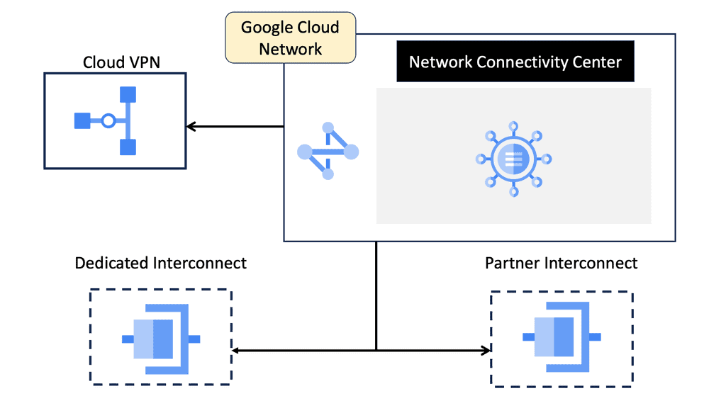
Google Network Connectivity Center (NCC) is a cloud-based service designed to simplify and centralize network management. By leveraging Google’s extensive global infrastructure, NCC provides organizations with a unified platform to manage their network connectivity across various environments, including on-premises data centers, multi-cloud setups, and hybrid environments.
**Key Features and Benefits**

1. **Centralized Network Management**: NCC offers a single pane of glass for network administrators to monitor and manage connectivity across different environments. This centralized approach reduces the complexity associated with managing multiple network endpoints and enhances operational efficiency.

2. **Enhanced Security**: With NCC, organizations can implement robust security measures across their network. The service supports advanced encryption protocols and integrates seamlessly with Google’s security tools, ensuring that data remains secure as it moves between different environments.

3. **Scalability and Flexibility**: One of the standout features of NCC is its ability to scale with your organization’s needs. Whether you’re expanding your data center operations or integrating new cloud services, NCC provides the flexibility to adapt quickly and efficiently.
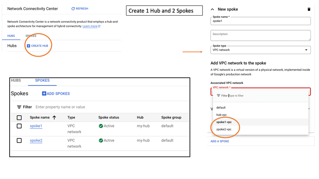
**Optimizing Data Center Operations**

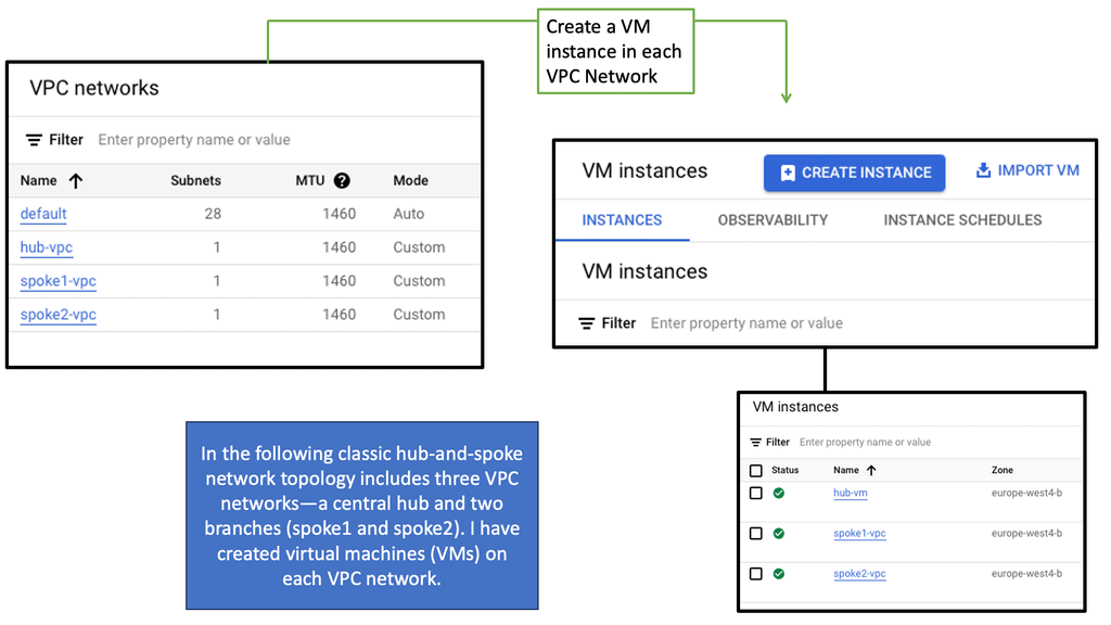
Data centers are the backbone of modern digital infrastructure, and optimizing their operations is crucial for any organization. NCC facilitates this by offering tools that enhance data center connectivity and performance. For instance, with NCC, you can easily set up and manage VPNs, interconnect data centers across different regions, and ensure high availability and redundancy.

**Seamless Integration with Other Google Services**

NCC isn’t just a standalone service; it integrates seamlessly with other Google Cloud services such as Cloud Interconnect, Cloud VPN, and Google Cloud Armor. This integration allows organizations to build comprehensive network solutions that leverage the best of Google’s cloud offerings. Whether it’s enhancing security, improving performance, or ensuring compliance, NCC works in tandem with other services to deliver a cohesive and powerful network management solution.

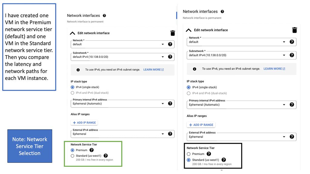
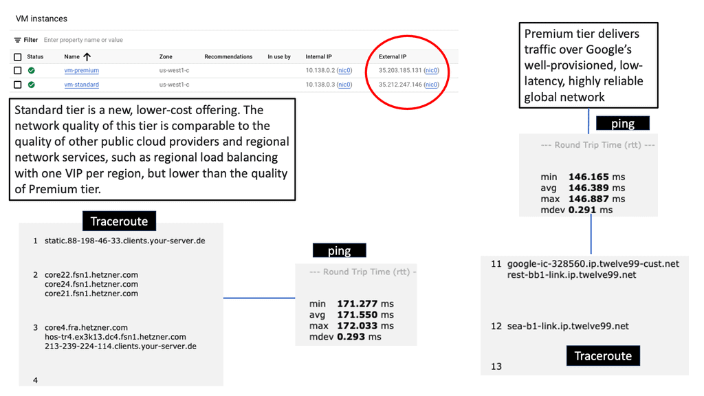
Understanding Network Tiers

Google Cloud offers two distinct Network Tiers: Premium Tier and Standard Tier. Each tier is designed to cater to specific use cases and requirements. The Premium Tier provides users with unparalleled performance, low latency, and high availability. On the other hand, the Standard Tier offers a more cost-effective solution without compromising on reliability.

The Premium Tier, powered by Google’s global fiber network, ensures lightning-fast connectivity and optimal performance for critical workloads. With its vast network of points of presence (PoPs), it minimizes latency and enables seamless data transfers across regions. By leveraging the Premium Tier, businesses can ensure superior user experiences and support demanding applications that require real-time data processing.

While the Premium Tier delivers exceptional performance, the Standard Tier presents an attractive option for cost-conscious organizations. By utilizing Google Cloud’s extensive network peering relationships, the Standard Tier offers reliable connectivity at a reduced cost. It is an ideal choice for workloads that are less latency-sensitive or require moderate bandwidth.
What is VPC Networking?

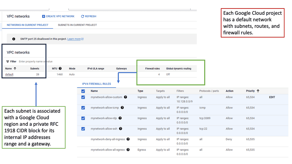
VPC networking refers to the virtual network environment that allows you to securely connect your resources running in the cloud. It provides isolation, control, and flexibility, enabling you to define custom network configurations to suit your specific needs. In Google Cloud, VPC networking is a fundamental building block for your cloud infrastructure.

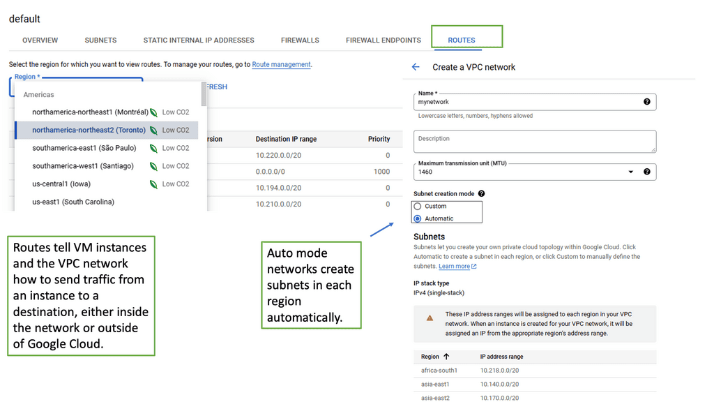
Google Cloud VPC networking offers a range of powerful features that enhance your network management capabilities. These include subnetting, firewall rules, route tables, VPN connectivity, and load balancing. Let’s explore each of these features in more detail:
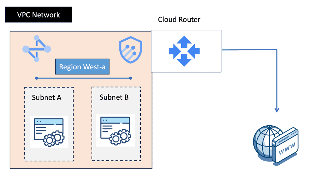
Subnetting: With VPC subnetting, you can divide your IP address range into smaller subnets, allowing for better resource allocation and network segmentation.

Firewall Rules: Google Cloud VPC networking provides robust firewall rules that enable you to control inbound and outbound traffic, ensuring enhanced security for your applications and data.

Route Tables: Route tables in VPC networking allow you to define the routing logic for your network traffic, ensuring efficient communication between different subnets and external networks.

VPN Connectivity: Google Cloud supports VPN connectivity, allowing you to establish secure connections between your on-premises network and your cloud resources, creating a hybrid infrastructure.

Load Balancing: VPC networking offers load balancing capabilities, distributing incoming traffic across multiple instances, increasing availability and scalability of your applications.
Example: DMVPN ( Dynamic Multipoint VPN)

Separating control from the data plane

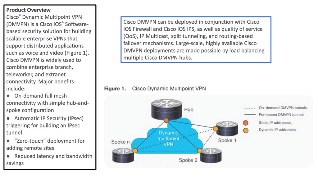
DMVPN is a Cisco-developed solution that combines the benefits of multipoint GRE tunnels, IPsec encryption, and dynamic routing protocols to create a flexible and efficient virtual private network. It simplifies network architecture, reduces operational costs, and enhances scalability. With DMVPN, organizations can connect remote sites, branch offices, and mobile users seamlessly, creating a cohesive network infrastructure.

The underlay infrastructure forms the foundation of DMVPN. It refers to the physical network that connects the different sites or locations. This could be an existing Wide Area Network (WAN) infrastructure, such as MPLS, or the public Internet. The underlay provides the transport for the overlay network, enabling the secure transmission of data packets between sites.

The overlay network is the virtual network created on top of the underlay infrastructure. It is responsible for establishing the secure tunnels and routing between the connected sites. DMVPN uses multipoint GRE tunnels to allow dynamic and direct communication between sites, eliminating the need for a hub-and-spoke topology. IPsec encryption ensures the confidentiality and integrity of data transmitted over the overlay network.

Example WAN Technology: Tunneling IPv6 over IPV4

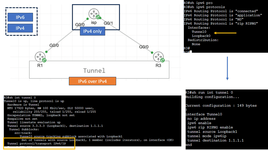
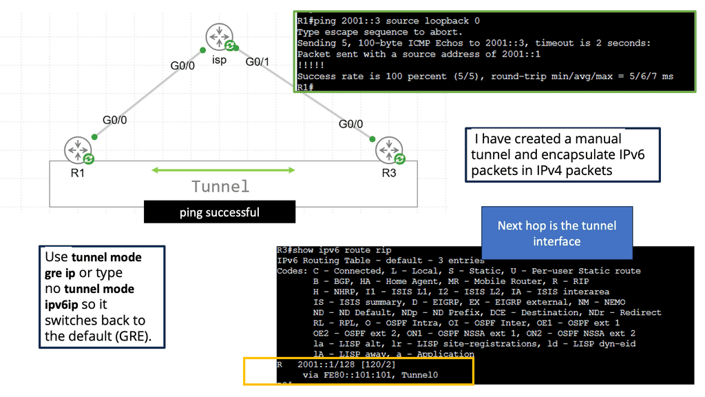
IPv6 tunneling is a technique that allows the transmission of IPv6 packets over an IPv4 network infrastructure. It enables communication between IPv6 networks by encapsulating IPv6 packets within IPv4 packets. By doing so, organizations can utilize existing IPv4 infrastructure while transitioning to IPv6. Before delving into its various implementations, understanding the basics of IPv6 tunneling is crucial.

Types of IPv6 Tunneling

There are several types of IPv6 tunneling techniques, each with its advantages and considerations. Let’s explore a few popular types:

Manual Tunneling: Manual tunneling is a simple method configuring tunnel endpoints. It also requires manually configuring tunnel interfaces on each participating device. While it provides flexibility and control, this approach can be time-consuming and prone to human error.

Automatic Tunneling: Automatic tunneling, also known as 6to4 tunneling, allows for the automatic creation of tunnels without manual configuration. It utilizes the 6to4 addressing scheme, where IPv6 packets are encapsulated within IPv4 packets using protocol 41. While convenient, automatic tunneling may encounter issues with address translation and compatibility.

Teredo Tunneling: Teredo tunneling is another automatic technique that enables IPv6 connectivity for hosts behind IPv4 Network Address Translation (NAT) devices. It uses UDP encapsulation to carry IPv6 packets over IPv4 networks. Though widely supported, Teredo tunneling may suffer from performance limitations due to its reliance on UDP.
WAN Virtualization Technologies

Understanding VRFs

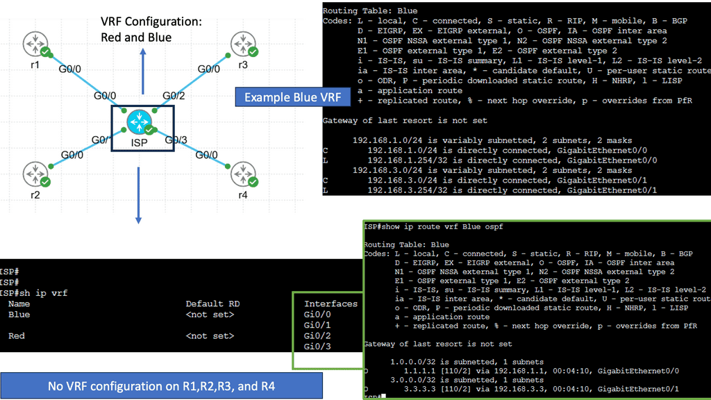
VRFs, in simple terms, allow the creation of multiple virtual routing tables within a single physical router or switch. Each VRF operates as an independent routing instance with its routing table, interfaces, and forwarding decisions. This powerful concept allows for logical separation of network traffic, enabling enhanced security, scalability, and efficiency.

One of VRFs’ primary advantages is network segmentation. By creating separate VRF instances, organizations can effectively isolate different parts of their network, ensuring traffic from one VRF cannot directly communicate with another. This segmentation enhances network security and provides granular control over network resources.

Furthermore, VRFs enable efficient use of network resources. By utilizing VRFs, organizations can optimize their routing decisions, ensuring that traffic is forwarded through the most appropriate path based on the specific requirements of each VRF. This dynamic routing capability leads to improved network performance and better resource utilization.

Use Cases for VRFs

VRFs are widely used in various networking scenarios. One common use case is in service provider networks, where VRFs separate customer traffic, allowing multiple customers to share a single physical infrastructure while maintaining isolation. This approach brings cost savings and scalability benefits.

Another use case for VRFs is in enterprise networks with strict security requirements. By leveraging VRFs, organizations can segregate sensitive data traffic from the rest of the network, reducing the risk of unauthorized access and potential data breaches.
Example WAN technology: Cisco PfR

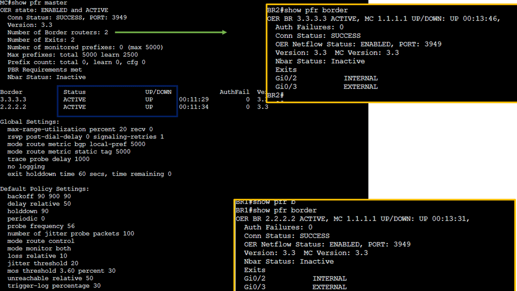
Cisco PfR is an intelligent routing solution that utilizes real-time performance metrics to make dynamic routing decisions. By continuously monitoring network conditions, such as latency, jitter, and packet loss, PfR can intelligently reroute traffic to optimize performance. Unlike traditional static routing protocols, PfR adapts to network changes on the fly, ensuring optimal utilization of available resources.

Key Features of Cisco PfR

a. Performance Monitoring: PfR continuously collects performance data from various sources, including routers, probes, and end-user devices. This data provides valuable insights into network behavior and helps identify areas of improvement.

b. Intelligent Traffic Engineering: With its advanced algorithms, Cisco PfR can dynamically select the best path for traffic based on predefined policies and performance metrics. This enables efficient utilization of available network resources and minimizes congestion.

c. Application Visibility and Control: PfR offers deep visibility into application-level performance, allowing network administrators to prioritize critical applications and allocate resources accordingly. This ensures optimal performance for business-critical applications and improves overall user experience.
Performance based routing

DMVPN and WAN Virtualization

Example WAN Technology: Network Overlay

Virtual network overlays serve as a layer of abstraction, enabling the creation of multiple virtual networks on top of a physical network infrastructure. By encapsulating network traffic within virtual tunnels, overlays provide isolation, scalability, and flexibility, empowering organizations to manage their networks efficiently.

Underneath the surface, virtual network overlays rely on encapsulation protocols such as Virtual Extensible LAN (VXLAN) or Generic Routing Encapsulation (GRE). These protocols enable the creation of virtual tunnels, allowing network packets to traverse the physical infrastructure while remaining isolated within their respective virtual networks.

**What is GRE?**

At its core, Generic Routing Encapsulation is a tunneling protocol that allows the encapsulation of different network layer protocols within IP packets. It acts as an envelope, carrying packets from one network to another across an intermediate network. GRE provides a flexible and scalable solution for connecting disparate networks, facilitating seamless communication.

GRE encapsulates the original packet, often called the payload, within a new IP packet. This encapsulated packet is then sent to the destination network, where it is decapsulated to retrieve the original payload. By adding an IP header, GRE enables the transportation of various protocols across different network infrastructures, including IPv4, IPv6, IPX, and MPLS.

**Introducing IPSec Services**

IPSec, short for Internet Protocol Security, is a suite of protocols that provides security services at the IP network layer. It offers data integrity, confidentiality, and authentication features, ensuring that data transmitted over IP networks remains protected from unauthorized access and tampering. IPSec operates in two modes: Transport Mode and Tunnel Mode.

**Combining GRE & IPSec**

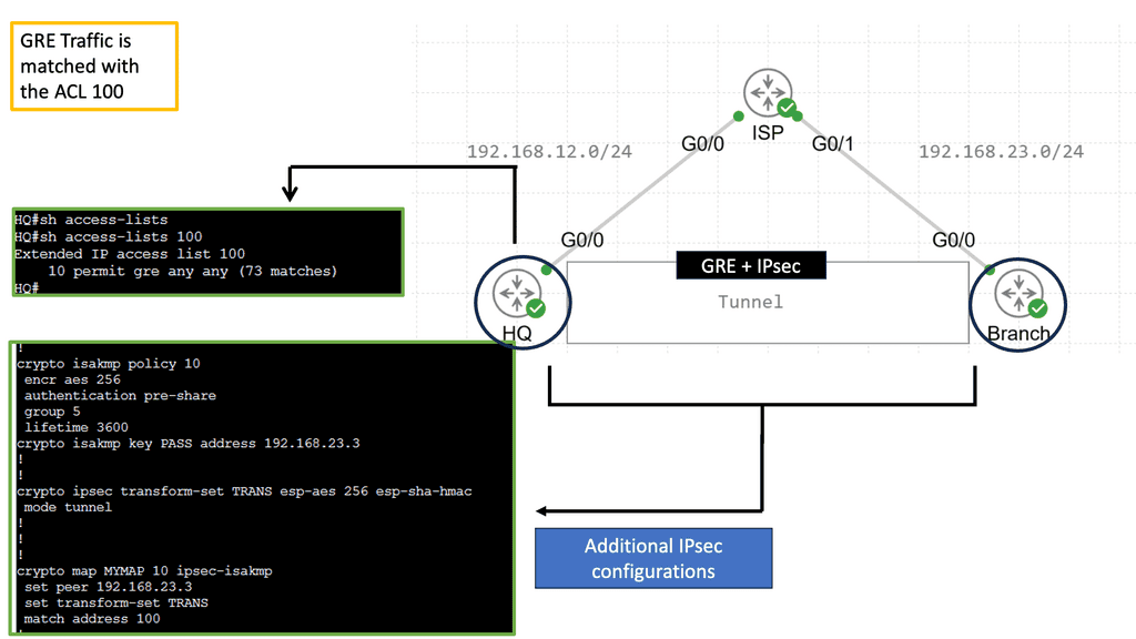
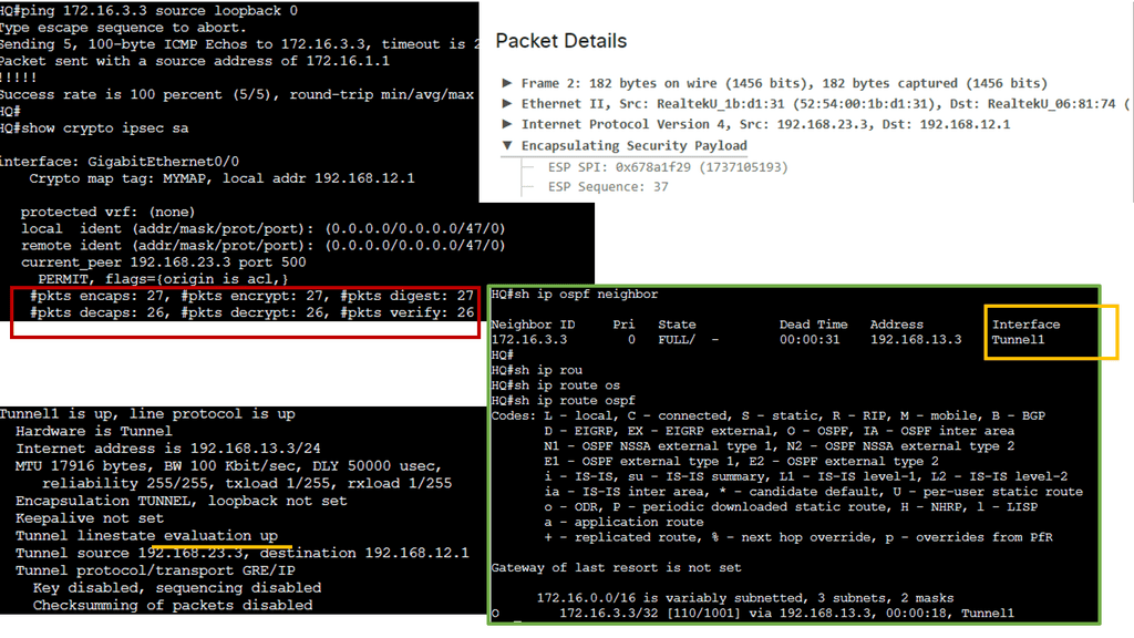
By combining GRE and IPSec, organizations can create secure and private communication channels over public networks. GRE provides the tunneling mechanism, while IPSec adds an extra layer of security by encrypting and authenticating the encapsulated packets. This combination allows for the secure transmission of sensitive data, remote access to private networks, and the establishment of virtual private networks (VPNs).

The combination of GRE and IPSec offers several advantages. First, it enables the creation of secure VPNs, allowing remote users to connect securely to private networks over public infrastructure. Second, it protects against eavesdropping and data tampering, ensuring the confidentiality and integrity of transmitted data. Lastly, GRE and IPSec are vendor-neutral protocols widely supported by various network equipment, making them accessible and compatible.
GRE with IPsec ipsec plus GRE

What is MPLS?

MPLS, short for Multi-Protocol Label Switching, is a versatile and scalable protocol used in modern networks. At its core, MPLS assigns labels to network packets, allowing for efficient and flexible routing. These labels help streamline traffic flow, leading to improved performance and reliability. To understand how MPLS works, we need to explore its key components.

The basic building block is the Label Switched Path (LSP), a predetermined path that packets follow. Labels are attached to packets at the ingress router, guiding them along the LSP until they reach their destination. This label-based forwarding mechanism enables MPLS to offer traffic engineering capabilities and support various network services.

Understanding Label Distributed Protocols

Label distributed protocols, or LDP, are fundamental to modern networking technologies. They are designed to establish and maintain label-switched paths (LSPs) in a network. LDP operates by distributing labels, which are used to identify and forward network traffic efficiently. By leveraging labels, LDP enhances network scalability and enables faster packet forwarding.

One key advantage of label-distributed protocols is their ability to support multiprotocol label switching (MPLS). MPLS allows for efficient routing of different types of network traffic, including IP, Ethernet, and ATM. This versatility makes label-distributed protocols highly adaptable and suitable for diverse network environments. Additionally, LDP minimizes network congestion, improves Quality of Service (QoS), and promotes effective resource utilization.

What is MPLS LDP?

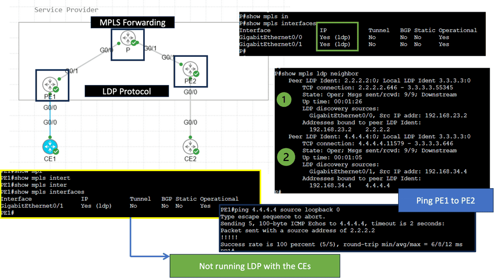
MPLS LDP, or Label Distribution Protocol, is a key component of Multiprotocol Label Switching (MPLS) technology. It facilitates the establishment of label-switched paths (LSPs) through the network, enabling efficient forwarding of data packets. MPLS LDP uses labels to direct network traffic along predetermined paths, eliminating the need for complex routing table lookups.

One of MPLS LDP’s primary advantages is its ability to enhance network performance. By utilizing labels, MPLS LDP reduces the time and resources required for packet forwarding, resulting in faster data transmission and reduced network congestion. Additionally, MPLS LDP allows for traffic engineering, enabling network administrators to prioritize certain types of traffic and allocate bandwidth accordingly.

Understanding MPLS VPNs

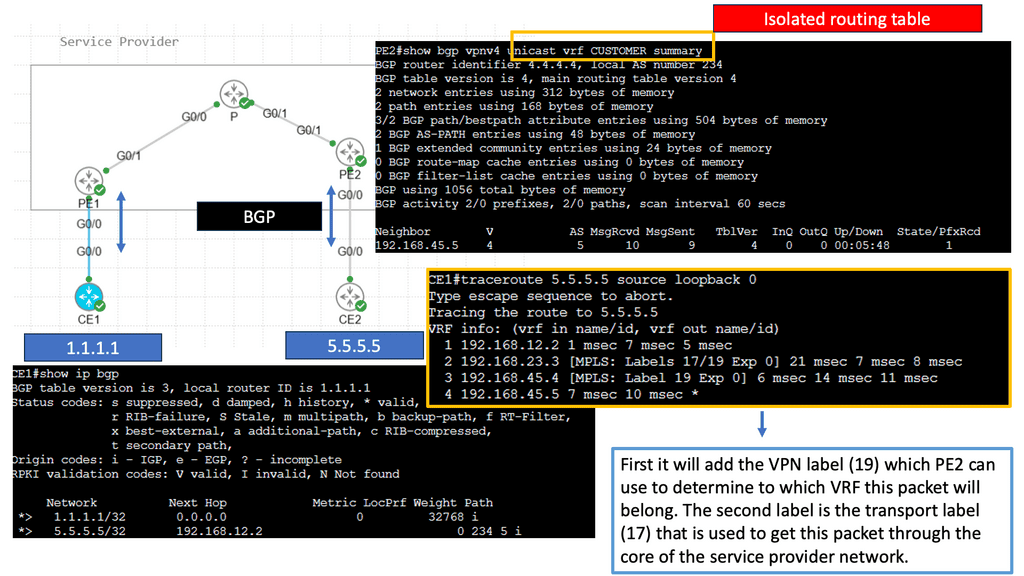
MPLS VPNs, or Multiprotocol Label Switching Virtual Private Networks, are network infrastructure that allows multiple sites or branches of an organization to communicate over a shared service provider network securely. Unlike traditional VPNs, MPLS VPNs utilize labels to efficiently route and prioritize data packets, ensuring optimal performance and security. By encapsulating data within labels, MPLS VPNs enable seamless communication between different sites while maintaining privacy and segregation.
Understanding VPLS

VPLS, short for Virtual Private LAN Service, is a technology that enables the creation of a virtual LAN (Local Area Network) over a shared or public network infrastructure. It allows geographically dispersed sites to connect as if they are part of the same LAN, regardless of their physical distance. This technology uses MPLS (Multiprotocol Label Switching) to transport Ethernet frames across the network efficiently.

Key Features and Benefits

Scalability and Flexibility: VPLS offers scalability, allowing businesses to easily expand their network as their requirements grow. It allows adding or removing sites without disrupting the overall network, making it an ideal choice for organizations with dynamic needs.

Seamless Connectivity: By extending the LAN across different locations, VPLS provides a seamless and transparent network experience. Employees can access shared resources, such as files and applications, as if they were all in the same office, promoting collaboration and productivity across geographically dispersed teams.

Enhanced Security: VPLS ensures a high level of security by isolating each customer’s traffic within their own virtual LAN. The data is encapsulated and encrypted, protecting it from unauthorized access. This makes VPLS a reliable solution for organizations that handle sensitive information and must comply with strict security regulations.

**Advanced WAN Designs**

DMVPN Phase 2 Spoke to Spoke Tunnels

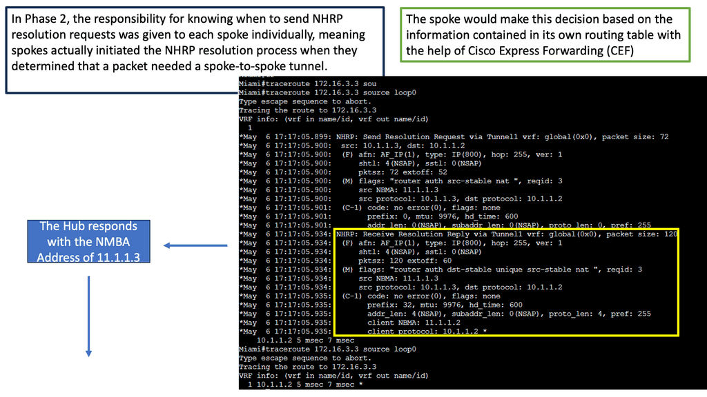
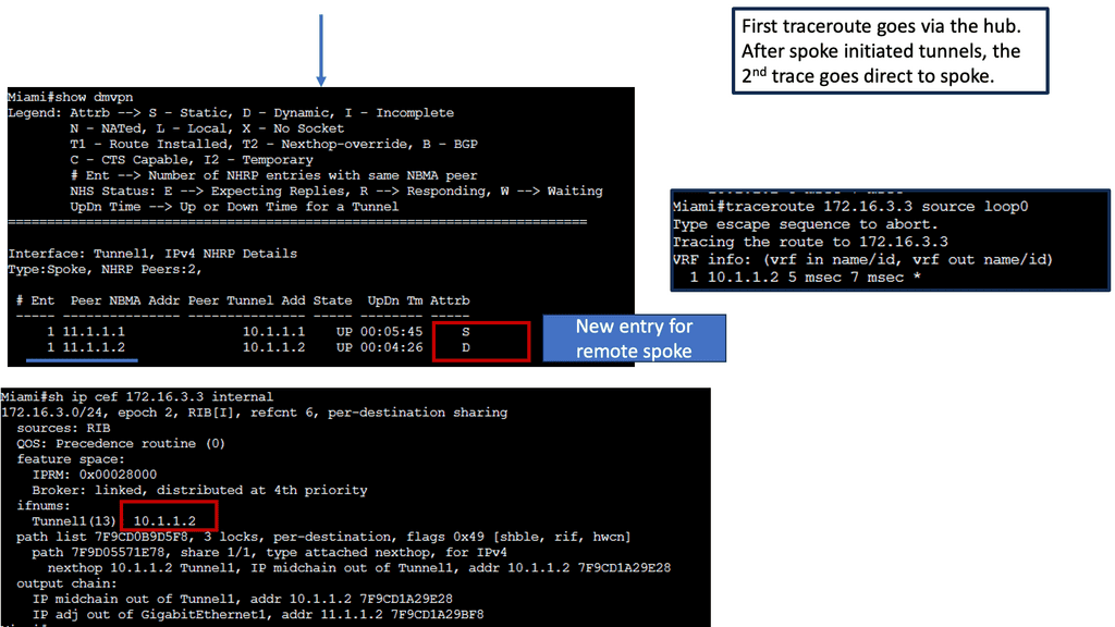
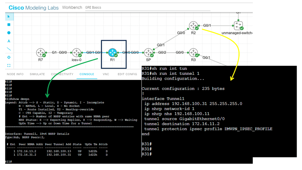
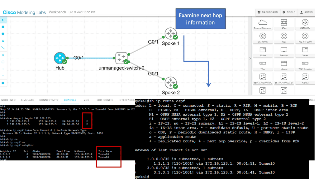
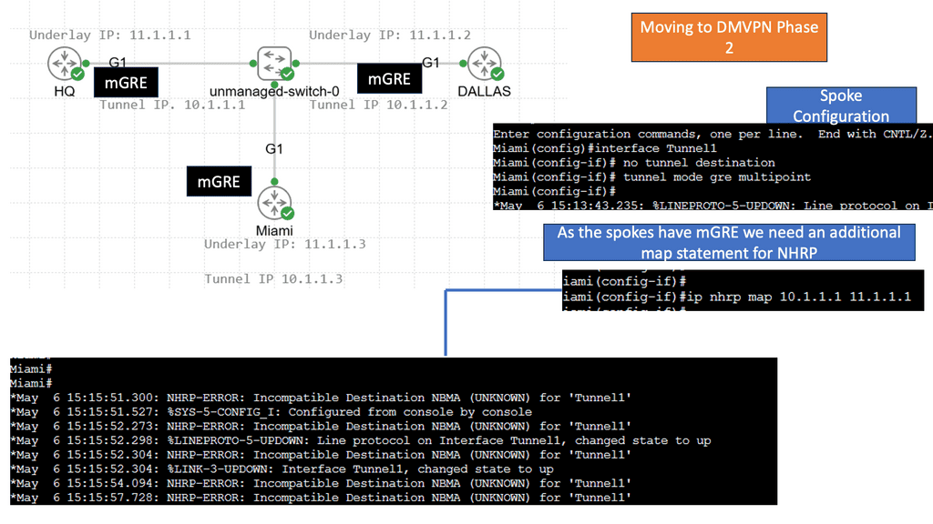
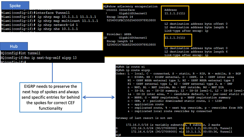
Learning the mapping information required through NHRP resolution creates a dynamic spoke-to-spoke tunnel. How does a spoke know how to perform such a task? As an enhancement to DMVPN Phase 1, spoke-to-spoke tunnels were first introduced in Phase 2 of the network. Phase 2 handed responsibility for NHRP resolution requests to each spoke individually, which means that spokes initiated NHRP resolution requests when they determined a packet needed a spoke-to-spoke tunnel. Cisco Express Forwarding (CEF) would assist the spoke in making this decision based on information contained in its routing table.
Exploring Single Hub Dual Cloud Architecture

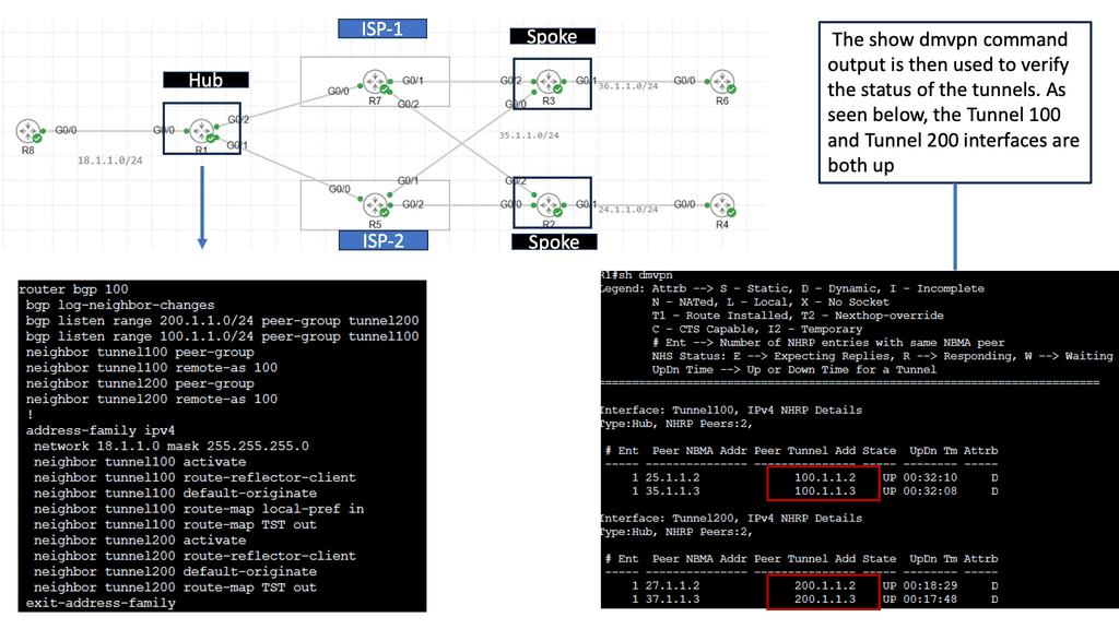
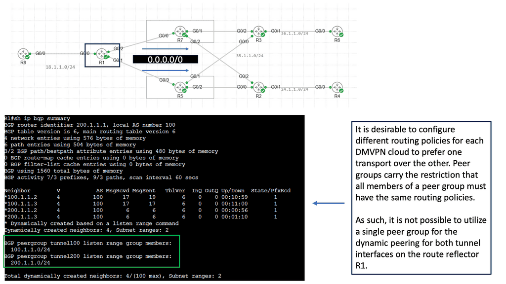
– Single Hub Dual Cloud is a specific deployment model within the DMVPN framework that provides enhanced redundancy and improved performance. This architecture connects a single hub device to two separate cloud service providers, creating two independent VPN clouds. This setup offers numerous advantages, including increased availability, load balancing, and optimized traffic routing.

– One key benefit of the Single Hub Dual Cloud approach is improved network resiliency. With two independent clouds, businesses can ensure uninterrupted connectivity even if one cloud or service provider experiences issues. This redundancy minimizes downtime and helps maintain business continuity. This architecture’s load-balancing capabilities also enable efficient traffic distribution, reducing congestion and enhancing overall network performance.

– Implementing DMVPN Single Hub Dual Cloud requires careful planning and configuration. Organizations must assess their needs, evaluate suitable cloud service providers, and design a robust network architecture. Working with experienced network engineers and leveraging automation tools can streamline deployment and ensure successful implementation.
WAN Services

Network Address Translation:

In simple terms, NAT is a technique for modifying IP addresses while packets traverse from one network to another. It bridges private local networks and the public Internet, allowing multiple devices to share a single public IP address. By translating IP addresses, NAT enables private networks to communicate with external networks without exposing their internal structure.

Types of Network Address Translation

There are several types of NAT, each serving a specific purpose. Let’s explore a few common ones:

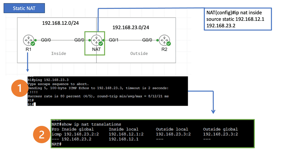
Static NAT: Static NAT, also known as one-to-one NAT, maps a private IP address to a public IP address. It is often used when specific devices on a network require direct access to the internet. With static NAT, inbound and outbound traffic can be routed seamlessly.

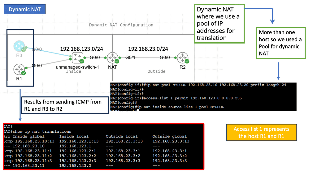
Dynamic NAT: On the other hand, Dynamic NAT allows a pool of public IP addresses to be shared among several devices within a private network. As devices connect to the internet, they are assigned an available public IP address from the pool. Dynamic NAT facilitates efficient utilization of public IP addresses while maintaining network security.

Port Address Translation (PAT): PAT, also called NAT Overload, is an extension of dynamic NAT. Rather than assigning a unique public IP address to each device, PAT assigns a unique port number to each connection. PAT allows multiple devices to share a single public IP address by keeping track of port numbers. This technique is widely used in home networks and small businesses.

NAT plays a crucial role in enhancing network security. By hiding devices’ internal IP addresses, it acts as a barrier against potential attacks from the Internet. External threats find it harder to identify and target individual devices within a private network. NAT acts as a shield, providing additional security to the network infrastructure.
PBR At the WAN Edge

Understanding Policy-Based Routing

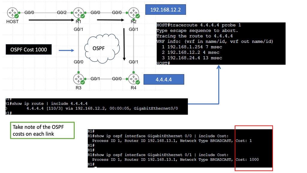
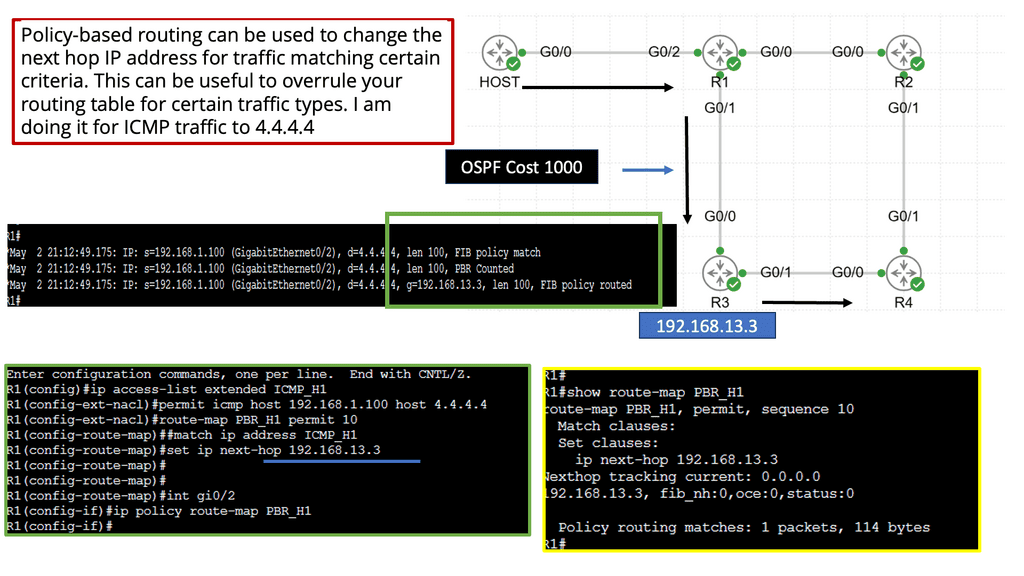
Policy-based Routing (PBR) allows network administrators to control the path of network traffic based on specific policies or criteria. Unlike traditional routing protocols, PBR offers a more granular and flexible approach to directing network traffic, enabling fine-grained control over routing decisions.

PBR offers many features and functionalities that empower network administrators to optimize network traffic flow. Some key aspects include:

1. Traffic Classification: PBR allows the classification of network traffic based on various attributes such as source IP, destination IP, protocol, port numbers, or even specific packet attributes. This flexibility enables administrators to create customized policies tailored to their network requirements.

2. Routing Decision Control: With PBR, administrators can define specific routing decisions for classified traffic. Traffic matching certain criteria can be directed towards a specific next-hop or exit interface, bypassing the regular routing table.

3. Load Balancing and Traffic Engineering: PBR can distribute traffic across multiple paths, leveraging load balancing techniques. By intelligently distributing traffic, administrators can optimize resource utilization and enhance network performance.
Performance at the WAN Edge

Understanding TCP MSS

TCP MSS refers to the maximum amount of data encapsulated in a single TCP segment. It determines the payload size within each TCP packet, excluding the TCP/IP headers. By limiting the MSS, TCP ensures that data is transmitted in manageable chunks, preventing fragmentation and improving overall network performance.

Several factors influence the determination of TCP MSS. One crucial aspect is the underlying network’s Maximum Transmission Unit (MTU). The MTU represents the largest packet size transmitted over a network without fragmentation. TCP MSS is typically set to match the MTU to avoid packet fragmentation and subsequent retransmissions.

By appropriately configuring TCP MSS, network administrators can optimize network performance. Matching the TCP MSS to the MTU size reduces the chances of packet fragmentation, which can lead to delays and retransmissions. Moreover, a properly sized TCP MSS can prevent unnecessary overhead and improve bandwidth utilization.

Adjusting the TCP MSS to suit specific network requirements is possible. Network administrators can configure the TCP MSS value on routers, firewalls, and end devices. This flexibility allows for fine-tuning network performance based on the specific characteristics and constraints of the network infrastructure.

WAN – The desired benefits

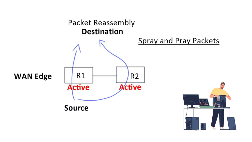
Businesses often want to replace or augment premium bandwidth services and switch from active/standby to active/active WAN transport models. This will reduce their costs. The challenge, however, is that augmentation can increase operational complexity. Creating a consistent operational model and simplifying IT requires businesses to avoid complexity.

The importance of maintaining remote site uptime for business continuity goes beyond simply preventing blackouts. Latency, jitter, and loss can affect critical applications and render them inoperable. As a result, the applications are entirely unavailable. The term “brownout” refers to these situations. Businesses today are focused on providing a consistent, high-quality application experience.

Ensuring connectivity

To ensure connectivity and make changes, there is a shift towards retaking control. It extends beyond routing or quality of service to include application experience and availability. The Internet edge is still not familiar to many businesses regarding remote sites. Software as a Service (SaaS) and productivity applications can be rolled out more effectively with this support.

Better access to Infrastructure as a Service (IaaS) is also necessary. Offloading guest traffic to branches with direct Internet connectivity is also possible. However, many businesses are interested in doing so. This is because offloading this traffic locally is more efficient than routing it through a centralized data center to consume WAN bandwidth. WAN bandwidth is wasted and is not efficient.

The shift to application-centric architecture

Business requirements are changing rapidly, and today’s networks cannot cope. It is traditionally more expensive and has a fixed capacity for hardware-centric networks. In addition, the box-by-box configuration approach, siloed management tools, and lack of automated provisioning make them more challenging to support.

They are inflexible, static, expensive, and difficult to maintain due to conflicting policies between domains and different configurations between services. As a result, security vulnerabilities and misconfigurations are more likely to occur. An application- or service-centric architecture focusing on simplicity and user experience should replace a connectivity-centric architecture.

Understanding Virtualization

Virtualization is a technology that allows the creation of virtual versions of various IT resources, such as servers, networks, and storage devices. These virtual resources operate independently from physical hardware, enabling multiple operating systems and applications to run simultaneously on a single physical machine. Virtualization opens possibilities by breaking the traditional one-to-one relationship between hardware and software. Now, virtualization has moved to the WAN.

WAN Virtualization and SD-WAN

Organizations constantly seek innovative solutions in modern networking to enhance their network infrastructure and optimize connectivity. One such solution that has gained significant attention is WAN virtualization. In this blog post, we will delve into the concept of WAN virtualization, its benefits, and how it revolutionizes how businesses connect and communicate.

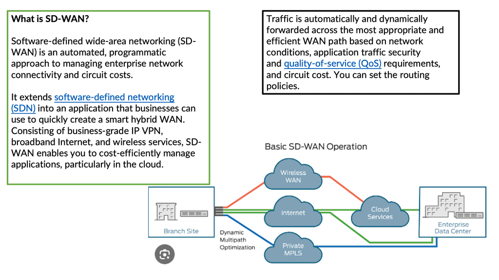
WAN virtualization, also known as Software-Defined WAN (SD-WAN), is a technology that enables organizations to abstract their wide area network (WAN) connections from the underlying physical infrastructure. It leverages software-defined networking (SDN) principles to decouple network control and data forwarding, providing a more flexible, scalable, and efficient network solution.

VPN and SDN Components

WAN virtualization is an essential technology in the modern business world. It creates virtualized versions of wide area networks (WANs) – networks spanning a wide geographic area. The virtualized WANs can then manage and secure a company’s data, applications, and services.

Regarding implementation, WAN virtualization requires using a virtual private network (VPN), a secure private network accessible only by authorized personnel. This ensures that only those with proper credentials can access the data. WAN virtualization also requires software-defined networking (SDN) to manage the network and its components.

Related: Before you proceed, you may find the following posts helpful:

  1. SD WAN Overlay
  2. Generic Routing Encapsulation
  3. WAN Monitoring
  4. SD WAN Security 
  5. Container Based Virtualization
  6. SD WAN and Nuage Networks

WAN Virtualization

Knowledge Check: Application-Aware Routing (AAR)

Understanding Application-Aware Routing (AAR)

Application-aware routing is a sophisticated networking technique that goes beyond traditional packet-based routing. It considers the unique requirements of different applications, such as video streaming, cloud-based services, or real-time communication, and optimizes the network path accordingly. It ensures smooth and efficient data transmission by prioritizing and steering traffic based on application characteristics.

Benefits of Application-Aware Routing

1- Enhanced Performance: Application-aware routing significantly improves overall performance by dynamically allocating network resources to applications with high bandwidth or low latency requirements. This translates into faster downloads, seamless video streaming, and reduced response times for critical applications.

2-  Increased Reliability: Traditional routing methods treat all traffic equally, often resulting in congestion and potential bottlenecks. Application Aware Routing intelligently distributes network traffic, avoiding congested paths and ensuring a reliable and consistent user experience. In network failure or congestion, it can dynamically reroute traffic to alternative paths, minimizing downtime and disruptions.

Implementation Strategies

1- Deep Packet Inspection: A key component of Application-Aware Routing is deep packet inspection (DPI), which analyzes the content of network packets to identify specific applications. DPI enables routers and switches to make informed decisions about handling each packet based on its application, ensuring optimal routing and resource allocation.

2- Quality of Service (QoS) Configuration: Implementing QoS parameters alongside Application Aware Routing allows network administrators to allocate bandwidth, prioritize specific applications over others, and enforce policies to ensure the best possible user experience. QoS configurations can be customized based on organizational needs and application requirements.

Future Possibilities

As the digital landscape continues to evolve, the potential for Application-Aware Routing is boundless. With emerging technologies like the Internet of Things (IoT) and 5G networks, the ability to intelligently route traffic based on specific application needs will become even more critical. Application-aware routing has the potential to optimize resource utilization, enhance security, and support the seamless integration of diverse applications and services.


WAN Challenges

Deploying and managing the Wide Area Network (WAN) has become more challenging. Engineers face several design challenges, such as traffic flow decentralizing, inefficient WAN link utilization, routing protocol convergence, and application performance issues with active-active WAN edge designs. Active-active WAN designs that spray and pray over multiple active links present technical and business challenges.

To do this efficiently, you have to understand application flows. There may also be performance problems. When packets reach the other end, there may be out-of-order packets as each link propagates at different speeds. The remote end has to be reassembled and put back together, causing jitter and delay. Both high jitter and delay are bad for network performance. To recap on WAN virtualization, including the drivers for SD-WAN, you may follow this SD WAN tutorial.

What is WAN Virtualization
Diagram: What is WAN virtualization? Source Linkedin.

Knowledge Check: Control and Data Plane

Understanding the Control Plane

The control plane can be likened to a network’s brain. It is responsible for making high-level decisions and managing network-wide operations. From routing protocols to network management systems, the control plane ensures data is directed along the most optimal paths. By analyzing network topology, the control plane determines the best routes to reach a destination and establishes the necessary rules for data transmission.

Unveiling the Data Plane

In contrast to the control plane, the data plane focuses on the actual movement of data packets within the network. It can be thought of as the hands and feet executing the control plane’s instructions. The data plane handles packet forwarding, traffic classification, and Quality of Service (QoS) enforcement tasks. It ensures that data packets are correctly encapsulated, forwarded to their intended destinations, and delivered with the necessary priority and reliability.

Use Cases and Deployment Scenarios

Distributed Enterprises:

For organizations with multiple branch locations, WAN virtualization offers a cost-effective solution for connecting remote sites to the central network. It allows for secure and efficient data transfer between branches, enabling seamless collaboration and resource sharing.

Cloud Connectivity:

WAN virtualization is ideal for enterprises adopting cloud-based services. It provides a secure and optimized connection to public and private cloud environments, ensuring reliable access to critical applications and data hosted in the cloud.

Disaster Recovery and Business Continuity:

WAN virtualization plays a vital role in disaster recovery strategies. Organizations can ensure business continuity during a natural disaster or system failure by replicating data and applications across geographically dispersed sites.

Challenges and Considerations:

Implementing WAN virtualization requires careful planning and consideration. Factors such as network security, bandwidth requirements, and compatibility with existing infrastructure need to be evaluated. It is essential to choose a solution that aligns with the specific needs and goals of the organization.

SD-WAN vs. DMVPN

Two popular WAN solutions are DMVPN and SD-WAN.

DMVPN (Dynamic Multipoint Virtual Private Network) and SD-WAN (Software-Defined Wide Area Network) are popular solutions to improve connectivity between distributed branch offices. DMVPN is a Cisco-specific solution, and SD-WAN is a software-based solution that can be used with any router. Both solutions provide several advantages, but there are some differences between them.

DMVPN is a secure, cost-effective, and scalable network solution that combines underlying technologies and DMVVPN phases (for example, the traditional DMVPN phase 1 ) to connect multiple sites. It allows the customer to use existing infrastructure and provides easy deployment and management. This solution is an excellent choice for businesses with many branch offices because it allows for secure communication and the ability to deploy new sites quickly.

DMVPN and WAN Virtualization

SD-WAN is a software-based solution that is gaining popularity in the enterprise market. It provides improved application performance, security, and network reliability. SD-WAN is an excellent choice for businesses that require high-performance applications across multiple sites. It provides an easy-to-use centralized management console that allows companies to deploy new sites and manage the network quickly.

Dynamic Multipoint VPN
Diagram: Example with DMVPN. Source is Cisco

Guide: DMVPN operating over the WAN

The following shows DMVPN operating over the WAN. The SP node represents the WAN network. Then we have R11 as the hub and R2, R3 as the spokes.  Several protocols make the DMVPM network over the WAN possible. We have GRE; in this case, the tunnel destination is specified as a point-to-point GRE tunnel instead of a mGRE tunnel.

Then we have NHRP, which is used to help create a mapping as this is a nonbroadcast network; we can not use ARP. So, we need to manually set this up on the spokes with the command: ip nhrp NHS 192.168.100.11

DMVPN configuration
Diagram: DMVPN Configuration.

Shift from network-centric to business intent.

The core of WAN virtualization involves shifting focus from a network-centric model to a business intent-based WAN network. So, instead of designing the WAN for the network, we can create the WAN for the application. This way, the WAN architecture can simplify application deployment and management.

First, however, the mindset must shift from a network topology focus to an application services topology. A new application style consumes vast bandwidth and is very susceptible to variations in bandwidth quality. Things such as jitter, loss, and delay impact most applications, which makes it essential to improve the WAN environment for these applications.

wan virtualization
Diagram: WAN virtualization.

The spray-and-pray method over two links increases bandwidth but decreases “goodput.” It also affects firewalls, as they will see asymmetric routes. When you want an active-active model, you need application session awareness and a design that eliminates asymmetric routing. It would help if you could slice the WAN properly so application flows can work efficiently over either link.

What is WAN Virtualization: Decentralizing Traffic

Decentralizing traffic from the data center to the branch requires more bandwidth to the network’s edges. As a result, we see many high-bandwidth applications running on remote sites. This is what businesses are now trying to accomplish. Traditional branch sites usually rely on hub sites for most services and do not host bandwidth-intensive applications. Today, remote locations require extra bandwidth, which is not cheaper yearly.

Inefficient WAN utilization

Redundant WAN links usually require a dynamic routing protocol for traffic engineering and failover. Routing protocols require complex tuning to load balance traffic between border devices. Border Gateway Protocol (BGP) is the primary protocol for connecting sites to external networks.

It relies on path attributes to choose the best path based on availability and distance. Although these attributes allow granular policy control, they do not cover aspects relating to path performance, such as Round Trip Time (RTT), delay, and jitter.

Port 179
Furthermore, BGP does not always choose the “best” path, which may have different meanings for customers. For example, customer A might consider the path via provider A as the best due to the price of links. Default routing does not take this into account. Packet-level routing protocols are not designed to handle the complexities of running over multiple transport-agnostic links. Therefore, a solution that eliminates the need for packet-level routing protocols must arise.
BGP Path Attributes
Diagram: BGP Path Attributes Source is Cisco.

Routing protocol convergence

WAN designs can also be active standby, which requires routing protocol convergence in the event of primary link failure. However, routing convergence is slow, and to speed up, additional features, such as Bidirectional Forwarding Detection (BFD), are implemented that may stress the network’s control plane. Although mechanisms exist to speed up convergence and failure detection, there are still several convergence steps, such as:

Rouitng Convergence

Convergence


Detect


Describe


Switch 


Find

Branch office security

With traditional network solutions, branches connect back to the data center, which typically provides Internet access. However, the application world has evolved, and branches directly consume applications such as Office 365 in the cloud. This drives a need for branches to access these services over the Internet without going to the data center for Internet access or security scrubbing.

Extending the security diameter into the branches should be possible without requiring onsite firewalls / IPS and other security paradigm changes. A solution must exist that allows you to extend your security domain to the branch sites without costly security appliances at each branch—essentially, building a dynamic security fabric.

WAN Virtualization

The solution to all these problems is SD-WAN ( software-defined WAN ). SD-WAN is a transport-independent overlay software-based networking deployment. It uses software and cloud-based technologies to simplify the delivery of WAN services to branch offices. Similar to Software Defined Networking (SDN), SD-WAN works by abstraction. It abstracts network hardware into a control plane with multiple data planes to make up one large WAN fabric.

SD-WAN in a nutshell 

When we consider the Wide Area Network (WAN) environment at a basic level, we connect data centers to several branch offices to deliver packets between those sites, supporting the transport of application transactions and services. The SD-WAN platform allows you to pull Internet connectivity into those sites, becoming part of one large transport-independent WAN fabric.

SD-WAN monitors the paths and the application performance on each link (Internet, MPLS, LTE ) and chooses the best path based on performance.

There are many forms of Internet connectivity (cable, DSL, broadband, and Ethernet). They are quick to deploy at a fraction of the cost of private MPLS circuits. SD-WAN provides the benefit of using all these links and monitoring which applications are best for them.

Application performance is continuously monitored across all eligible paths-direct internet, internet VPN, and private WAN. It creates an active-active network and eliminates the need to use and maintain traditional routing protocols for active-standby setups—no reliance on the active-standby model and associated problems.

WAN virtualization
Diagram: WAN virtualization. Source is Juniper

SD-WAN simplifies WAN management

SD-WAN simplifies managing a wide area network by providing a centralized platform for managing and monitoring traffic across the network. This helps reduce the complexity of managing multiple networks, eliminating the need for manual configuration of each site. Instead, all of the sites are configured from a single management console.

SD-WAN also provides advanced security features such as encryption and firewalling, which can be configured to ensure that only authorized traffic is allowed access to the network. Additionally, SD-WAN can optimize network performance by automatically routing traffic over the most efficient paths.

what is wan virtualization

SD-WAN Packet Steering

SD-WAN packet steering is a technology that efficiently routes packets across a wide area network (WAN). It is based on the concept of steering packets so that they can be delivered more quickly and reliably than traditional routing protocols. Packet steering is crucial to SD-WAN technology, allowing organizations to maximize their WAN connections.

SD-WAN packet steering works by analyzing packets sent across the WAN and looking for patterns or trends. Based on these patterns, the SD-WAN can dynamically route the packets to deliver them more quickly and reliably. This can be done in various ways, such as considering latency and packet loss or ensuring the packets are routed over the most reliable connections.

Spraying packets down both links can result in 20% drops or packet reordering. SD-WAN makes packets better utilized, no reorder, and better “goodput.” SD-WAN increases your buying power and results in buying lower bandwidth links and running them more efficiently. Over-provision is unnecessary as you are using the existing WAN bandwidth better.

Example WAN Security Technology: Suricata

A Final Note: WAN virtualization

Server virtualization and automation in the data center are prevalent, but WANs are stalling in this space. It is the last bastion of hardware models that has complexity. Like hypervisors have transformed data centers, SD-WAN aims to change how WAN networks are built and managed. When server virtualization and hypervisor came along, we did not have to worry about the underlying hardware. Instead, a virtual machine (VM) can be provided and run as an application. Today’s WAN environment requires you to manage details of carrier infrastructure, routing protocols, and encryption. 

  • SD-WAN pulls all WAN resources together and slices up the WAN to match the applications on them.

The Role of WAN Virtualization in Digital Transformation:

In today’s digital era, where cloud-based applications and remote workforces are becoming the norm, WAN virtualization is critical in enabling digital transformation. It empowers organizations to embrace new technologies, such as cloud computing and unified communications, by providing secure and reliable connectivity to distributed resources.

Summary: WAN Virtualization

In our ever-connected world, seamless network connectivity is necessary for businesses of all sizes. However, traditional Wide Area Networks (WANs) often fall short of meeting the demands of modern data transmission and application performance. This is where the concept of WAN virtualization comes into play, promising to revolutionize network connectivity like never before.

Understanding WAN Virtualization

WAN virtualization, also known as Software-Defined WAN (SD-WAN), is a technology that abstracts the physical infrastructure of traditional WANs and allows for centralized control, management, and optimization of network resources. By decoupling the control plane from the underlying hardware, WAN virtualization enables organizations to dynamically allocate bandwidth, prioritize critical applications, and ensure optimal performance across geographically dispersed locations.

The Benefits of WAN Virtualization

Enhanced Flexibility and Scalability: With WAN virtualization, organizations can effortlessly scale their network infrastructure to accommodate growing business needs. The virtualized nature of the WAN allows for easy addition or removal of network resources, enabling businesses to adapt to changing requirements without costly hardware upgrades.

Improved Application Performance: WAN virtualization empowers businesses to optimize application performance by intelligently routing network traffic based on application type, quality of service requirements, and network conditions. By dynamically selecting the most efficient path for data transmission, WAN virtualization minimizes latency, improves response times, and enhances overall user experience.

Cost Savings and Efficiency: By leveraging WAN virtualization, organizations can reduce their reliance on expensive Multiprotocol Label Switching (MPLS) connections and embrace more cost-effective broadband links. The ability to intelligently distribute traffic across diverse network paths enhances network redundancy and maximizes bandwidth utilization, providing significant cost savings and improved efficiency.

Implementation Considerations

Network Security: When adopting WAN virtualization, it is crucial to implement robust security measures to protect sensitive data and ensure network integrity. Encryption protocols, threat detection systems, and secure access controls should be implemented to safeguard against potential security breaches.

Quality of Service (QoS): Organizations should prioritize critical applications and allocate appropriate bandwidth resources through Quality of Service (QoS) policies to ensure optimal application performance. By adequately configuring QoS settings, businesses can guarantee mission-critical applications receive the necessary network resources, minimizing latency and providing a seamless user experience.

Real-World Use Cases

Global Enterprise Networks

Large multinational corporations with a widespread presence can significantly benefit from WAN virtualization. These organizations can achieve consistent performance across geographically dispersed locations by centralizing network management and leveraging intelligent traffic routing, improving collaboration and productivity.

Branch Office Connectivity

WAN virtualization simplifies connectivity and network management for businesses with multiple branch offices. It enables organizations to establish secure and efficient connections between headquarters and remote locations, ensuring seamless access to critical resources and applications.

In conclusion, WAN virtualization represents a paradigm shift in network connectivity, offering enhanced flexibility, improved application performance, and cost savings for businesses. By embracing this transformative technology, organizations can unlock the true potential of their networks, enabling them to thrive in the digital age.