
Neutron Network

Neutron Network

OpenStack Neutron provides the networking services that allow OpenStack cloud workloads to communicate with one another, with external networks, and with other infrastructure. Rather than treating networking as a fixed physical configuration, Neutron exposes networking capabilities through APIs so that cloud tenants and operators can create and manage virtual networks, subnets, ports, routers, security controls, and related services programmatically.

Neutron’s Role in OpenStack: Neutron is the networking service within the OpenStack architecture. It provides the control-plane API and abstractions required to create and manage network resources, while the underlying networking implementation is responsible for forwarding traffic. This separation allows OpenStack deployments to use different technologies and architectures underneath the common Neutron API.

Networks, Subnets, and Ports: A Neutron network represents a logical Layer 2 network. Subnets define IP addressing and allocation within that network, while ports represent logical connection points to which virtual machine or other resources can attach. Together, these abstractions allow workloads to be connected without requiring administrators to manually configure the physical network for every virtual machine.

Tenant and Provider Networks: Neutron can support different networking models depending on the deployment. Tenant networks provide isolated logical networks for cloud projects, while provider networks can connect workloads more directly to physical or external networks. These models can be combined so that private tenant networks use virtual routing and controlled connectivity while selected workloads or services obtain access to external infrastructure.

Virtual Routers and External Connectivity: Neutron routers provide Layer 3 connectivity between logical networks and can provide access toward external networks. A common cloud design might place virtual machines on a private tenant network while using a Neutron router to provide controlled north-south connectivity. Features such as floating IPs can provide externally reachable addresses without requiring the workload’s private address to be directly exposed.

Security Groups: Security groups provide stateful traffic filtering associated with ports and instances. They can control which traffic is permitted to and from workloads based on characteristics such as protocol, port, and source or destination. Security groups therefore form an important part of the cloud network security model, although they should be considered alongside infrastructure firewalls, network segmentation, identity controls, and host security.

Networking Backends: Neutron does not require a single underlying implementation. Modern OpenStack environments can use networking technologies such as Open Virtual Network (OVN) and Open vSwitch, while other deployments may use different mechanisms depending on their architecture and requirements. The Neutron API provides a consistent management model while the backend determines how logical networking is translated into actual forwarding behaviour.

Control Plane and Data Plane: A useful way to understand Neutron is to separate the control plane from the data plane. The Neutron API receives requests to create networks, ports, routers, security rules, and other resources. The networking backend then translates the desired state into the forwarding, switching, routing, filtering, and tunnel configuration required to move packets. This distinction is important when troubleshooting because a resource can appear correctly configured in the control plane while a data-plane problem prevents traffic from flowing.

Network Segmentation and Overlay Networking: Cloud environments often require many isolated networks to coexist on the same physical infrastructure. Technologies such as VLANs and overlay networks can provide this separation. Depending on the deployment architecture, encapsulation mechanisms such as VXLAN or Geneve may be used to carry tenant traffic across the underlying network. The physical network therefore provides transport while the virtual network layer provides logical connectivity and isolation.

Advanced Networking Services: Neutron can also integrate with additional networking services and extensions for capabilities such as Quality of Service, load balancing, firewalling, routing, and high-availability mechanisms. These capabilities allow operators to build networking environments that are much more sophisticated than simple virtual switching.

Scalability and Operations: Large OpenStack environments introduce challenges around control-plane scale, distributed forwarding, tunnel endpoints, failure domains, network state, observability, and operational complexity. Modern deployments therefore need careful architectural planning around controller placement, networking agents or backend controllers, physical network capacity, MTU, high availability, and failure recovery.

Observability and Troubleshooting: Troubleshooting Neutron requires following the packet through multiple layers. An engineer may need to examine the instance interface, Neutron port, security group rules, logical switch, router, overlay tunnel, provider network, external gateway, and physical network. Packet captures, flow information, Open vSwitch or OVN state, Neutron API resources, and infrastructure telemetry can help determine where forwarding or policy enforcement is failing.

A simplified Neutron traffic model can therefore be represented as:

Instance → Neutron Port → Logical Network → Virtual Router → External/Provider Network → Physical Network

The exact path depends on the deployment and backend, but the architectural principle remains the same: Neutron provides programmable network abstractions while the underlying networking implementation turns those abstractions into packet-forwarding behaviour.

Neutron is therefore best understood not simply as an SDN product, but as the networking control and abstraction layer for OpenStack cloud infrastructure. Its combination of logical networks, subnets, ports, virtual routing, security controls, provider connectivity, and pluggable networking backends allows cloud operators to build programmable and isolated network environments at scale.

OpenStack Neutron Visual Lab

From Logical Network to VM Connectivity

Neutron separates the network you describe from the infrastructure that implements it. Explore how logical networks, subnets, ports and routers become a virtual forwarding path for workloads.
Neutron Logical Model TENANT NETWORK
API / Intent
☁️
Network
tenant-net
🔢
Subnet
10.10.0.0/24
🔌
Port
VM interface
Virtual Data Plane
🌉
Virtual Switch
L2 connectivity
↗️
Router
optional L3 path
🛡️
Services
security / extensions
Workloads
🖥️
VM-A
10.10.0.11
🖥️
VM-B
10.10.0.12
🌐
External
provider network
Trace a Traffic Flow
What Neutron Is Doing
Abstraction
Logical
Forwarding
L2
Addressing
IPAM
Isolation
Tenant
External Path
Optional
Flow State
Ready
Architecture Explanation
Tenant network: Neutron lets the operator define a logical network and subnet without requiring the workload to understand the underlying physical switching infrastructure. Ports provide the attachment point between workloads and the logical network.
Key Lesson
Separate intent from implementation. Neutron stores and exposes the logical networking model while drivers and agents translate that model into forwarding behaviour on the infrastructure.

Highlights: Neutron Network

Understanding Neutron Network

Neutron Network is an open-source networking project that provides networking services to virtual machines and containers within an OpenStack environment. It serves as the networking component of OpenStack, enabling users to create and manage networks, subnets, routers, and security groups. By abstracting the underlying network infrastructure, Neutron Network offers flexibility, scalability, and simplified network management.

Neutron Network boasts an impressive array of features that empower users to build robust and secure networks. Some of its key features include:

1. Network Abstraction: Neutron Network allows users to define and manage networks using a variety of network types, such as flat, VLAN, VXLAN, or GRE. This flexibility enables seamless integration with existing network infrastructure.

2. Security Groups: With Neutron Network, users can define security groups and associated rules to control traffic flow and enforce security policies. This granular level of security helps protect workloads from unauthorized access and potential threats.

3. Load Balancing: Neutron Network offers built-in load balancing capabilities, allowing users to distribute traffic across multiple instances. This ensures high availability, scalability, and optimal performance for applications and services.

Neutron Network finds application in various scenarios, catering to a wide range of use cases. Some notable use cases include:

1. Multi-Tenant Environments: Neutron Network enables the creation of isolated networks for different tenants within an OpenStack cloud. This segregation ensures secure and independent network environments, making it ideal for service providers and enterprises with multiple clients.

2. NFV (Network Function Virtualization): Neutron Network plays a crucial role in NFV deployments, where network functions are virtualized. It facilitates the creation and management of virtual network functions (VNFs), enabling efficient network service delivery and orchestration.

The need for virtual networking

A: ) Due to the proliferation of devices in data centers, today’s networks contain more devices than ever. Servers, switches, routers, storage systems, and security appliances are now available as virtual machines and virtual network appliances. A scalable, automated approach is needed to manage next-generation networks. Thanks to its flexibility, control, and provisioning time, users can control their infrastructure more easily and quickly with OpenStack.

B: ) OpenStack Networking is a pluggable, scalable, API-driven system that manages networks and IP addresses on OpenStack clouds. Like other core OpenStack components, It allows users and administrators to maximize the value and utilization of existing data center resources. Unlike Nova (computing), Glance (images), Keystone (identity), Cinder (block storage), or Horizon (dashboard), Neutron (Networking) is a stand-alone service. To provide resiliency and redundancy, OpenStack Networking can be configured to run on a single server or distributed across multiple hosts.

C: ) With OpenStack Networking, users can request additional processing through an application programmable interface or API. Cloud operators can enhance and power the cloud by defining network connectivity with different networking technologies. Access to a database is required for Neutron to store network configurations persistently.

Understanding Open vSwitch

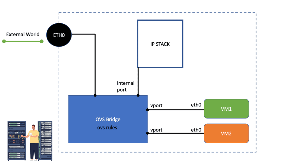
Open vSwitch, often called OVS, is a multi-layer virtual switch that enables network automation and virtualization. It is designed to work seamlessly with hypervisors, containers, and cloud environments, providing a flexible and scalable networking solution. By integrating with various virtualization technologies, Open vSwitch allows for efficient network traffic management, ensuring optimal performance and reliability.

Features and Benefits of Open vSwitch

Open vSwitch offers an array of features that make it a preferred choice for network administrators and developers. Some key features include support for standard management interfaces, virtual and physical network integration, VLAN and VXLAN support, and flow-based forwarding. Additionally, OVS supports advanced features like Quality of Service (QoS), network slicing, and load balancing, empowering network operators to create dynamic and efficient networks.

OVS Use Cases

Open vSwitch finds applications in a wide range of use cases. One prominent use case is network virtualization, where OVS enables the creation of virtual networks isolated from the physical infrastructure. This allows for better resource utilization, enhanced security, and simplified network management.

OVS is also extensively used in cloud environments, facilitating seamless connectivity and virtual machine migration across data centers. Furthermore, Open vSwitch is leveraged in Software-Defined Networking (SDN) deployments, enabling centralized network control and programmability.
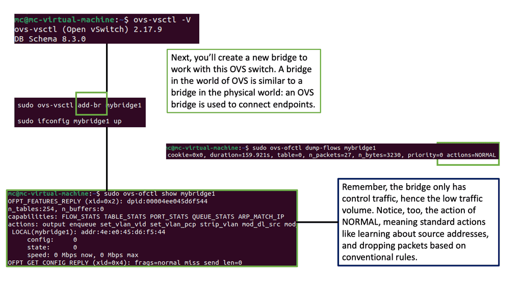
**Application Program Interface**

Neutron’s pluggable application program interface ( API ) architecture enables the management of network services for container networking in public or private cloud environments. The API allows users to interact with neutron networking constructs, such as routers and switches, enabling instance reachability. The OpenStack Neutron and OpenStack network types were initially built into Nova but lacked flexibility for advanced designs. It was helpful for large Layer 2 networks, but most environments require better multi-tenancy with advanced load balancing and firewalling functionality.

**Decoupled Layer 3 Approach**

The limited networking functionality gave Neutron, which offers a decoupled Layer 3 approach. It operates an Agent-Database model where the API receives and sends calls to agents installed locally on the hosts. Without this efficiency, there won’t be any communication and connectivity between your host’s platforms, which can sometimes affect productivity.


OpenStack Neutron · Experiment Lab

Build a Virtual Network

Change the network model and see how Neutron can provide tenant isolation, virtual switching, routing and overlay connectivity. The simulation is conceptual: it focuses on the networking decisions rather than a specific deployment implementation.

Logical Packet Path
Tenant A VM / Port
10.10.1.10
Virtual Switch Neutron network
Logical L2 domain
Neutron Router Layer 3
Namespace / routing
Tenant B VM / Port
10.20.1.20
VXLAN provides a logical overlay between hosts while the virtual router represents the Layer 3 boundary between tenant networks.
Network State
Ready for test
Segmentation Logical
Encapsulation VXLAN
L3 Boundary Router
Isolation Enabled
Event Console
neutron-lab: ready
logical network: VXLAN
waiting for traffic test...
Engineering Insight
Think in layers: Neutron defines the logical network model, while plugins and mechanism drivers translate that model into implementation-specific networking behaviour.

Neutron Network

Understanding Neutron’s Architecture

Neutron’s architecture is designed to be highly modular and pluggable, allowing operators to choose from a wide array of network services and plugins. At its core, Neutron consists of several components, including the Neutron server, plugins, and agents. The Neutron server is responsible for managing the high-level network state, while plugins handle the actual configuration of the low-level networking details across different technologies. Agents work as the intermediaries, ensuring that the network state is correctly applied to the physical or virtual network infrastructure.

**Advantages of Using Neutron in OpenStack**

Neutron provides several advantages for cloud administrators and users. Its modular architecture allows for flexibility and customization to meet the specific networking needs of different organizations. Additionally, Neutron supports advanced networking features such as security groups, floating IPs, and VPN services, which enhance the security and functionality of cloud deployments. By utilizing Neutron, organizations can efficiently manage their network resources, ensuring high availability and performance.

**Challenges and Considerations**

While Neutron offers numerous benefits, it also presents some challenges. Configuring and managing Neutron can be complex, especially in large-scale deployments. It’s essential to have a deep understanding of networking concepts and OpenStack’s architecture to avoid potential pitfalls. Additionally, integrating Neutron with existing network infrastructure may require careful planning and coordination.

Key Features and Benefits:

1. Network Virtualization: Neutron Network leverages network virtualization technologies such as VLANs, VXLANs, and GRE tunnels to create isolated virtual networks. This allows tenants to have complete control over their network resources without interference from other tenants.

2. Scalability: Neutron’s distributed architecture can scale horizontally to accommodate many virtual networks and instances. This ensures that cloud environments can handle increased workloads without compromising performance.

3. Network Segmentation: Neutron Network supports network segmentation, allowing tenants to partition their virtual networks based on specific requirements. This enables better network isolation, security, and performance optimization.

4. Flexible Network Topologies: Neutron provides the flexibility to create a variety of network topologies, including flat networks, VLAN-based networks, and overlay networks. This adaptability empowers users to design their networks according to their unique needs.

5. Integration with Security Services: Neutron Network integrates seamlessly with OpenStack’s security services, such as Firewall-as-a-Service (FWaaS) and Virtual Private Network-as-a-Service (VPNaaS). This integration enhances network security by providing additional layers of protection.

6. Load Balancing and VPN Services: Neutron Network offers load balancing services, allowing users to distribute network traffic across multiple instances for improved performance and reliability. Additionally, it supports VPN services to establish secure connections between different networks or remote users.

Neutron Network Architecture:

Under the hood, Neutron Network consists of several components working together to provide a robust networking service. The main elements include:

– Neutron API: Provides a RESTful API for users to interact with Neutron Network and manage their network resources.

– Neutron Core Plugin: The central component responsible for handling network-related requests and managing network plugins.

– Neutron Agents: Various agents, such as the DHCP agent, L3 agent, and OVS agent, ensure the smooth operation of the Neutron Network by handling specific tasks like DHCP allocation, routing, and switching.

– Network Plugins: Neutron supports multiple plugins, such as the Open vSwitch (OVS) plugin and the Linux Bridge plugin, which provide different network virtualization capabilities and integrate with various networking technologies.

OpenStack Network Types

Logical network information is stored in the database. Plugins and agents extract the data and carry out the necessary low-level functions to pin the virtual network, enabling instance connectivity. For example, the Open vSwitch agent converts information in the Neutron database to Open vSwitch flow while maintaining the local flows to match the network design following topology changes. Agents and plugins build the network based on the logical data model. The screenshot below illustrates the agent-to-host installation.

openstack network types

Neutron Networking: Network, Subnets, and Ports

Neutron consists of four elements that form the foundation for OpenStack Network Types. The configuration consists of the following entities: Networks, Subnets, and Ports. A network is a standard Layer 2 broadcast domain in which subnets and ports are assigned. A subnet is an IPv4 or IPv6 address block ( IPAM—IP Address Management) posted to a network.

A port is a connection point with properties similar to those of a physical port, except that it is virtual. Ports have media access control addresses ( MAC ) and IP addresses. All port information is stored in the Neutron database, which plugins/agents use to stitch and build the virtual infrastructure. 

Neutron networking features

Neutron networks enable core networking and the potential for much more once the appropriate extension and plugin are activated. Extensions enhance plugins to provide additional network functionality. Due to its pluggable architecture, Neutron can be extended with third-party open-source or proprietary products, for example, an SDN OpenDaylight controller for advanced centralized functionality. 

While Neutron does offer an API for network interaction, it does not provide an API to manage the network. Integrating an SDN controller with Neutron enables a centralized viewpoint and management entity for the entire network infrastructure, not just individual pieces.

Some vendor plugins complement Neutron, while others completely replace it. Advancements have been made to Neutron in an attempt to make it more “production-ready,” but some of these features are still at the experimental stage. There are bugs in all platforms, but generally, early-release features should be kept in nonproduction environments.

Virtual switches, routing, and advanced services

Virtual switches are software switches that connect VM instances at Layer 2. Any communication outside that boundary requires a Layer 3 router, either physical or virtual. Neutron has built-in support for Linux Bridges and Open vSwitch virtual switches. Overlay networking, the foundation for multi-tenancy for cloud computing, is supported in both. 

Layer 3 routing permits external connectivity and connectivity between VMs in different subnets. Routing is enabled through IP forwarding rules, IPtables, and network namespaces.

IPtables provide ingress/egress filtering throughout different parts of the network (for example, perimeter edge or local compute ), namespaces provide network stack isolation, and IP forwarding rules provide forwarding. Firewalling and security services are based on Security Groups or FWaaS (FireWall-as-a-Service).

They can be used in conjunction for better depth defense. Both operate with IPtables but differ in network placement.

Security group IPtable rules are configured locally on ports corresponding to the compute node hosting the instance. Implementation is close to the actual workload, offering finer-grained filleting. Firewall IPtable rules are at the network’s edge on Neutron routers ( namespaces ), filtering perimeter traffic.

Load balancing enables requests to be distributed to multiple instances. Dispersing load to numerous hosts offers advantages similar to those of the traditional world. The plugin is based on open-source HAProxy. Finally, VPNs allow operators to extend the network securely with IPSec-based VPN tunnels. 

Virtual network preparation

The diagram below displays the initial configuration and physical interface assignments for a standard neutron deployment. The reference model consists of a controller, network, and compute nodes. The compute nodes are restricted to provide compute resources, while the controller/network node may be combined or separated for all other services.

Separating services on the compute nodes allows compute services to be scaled horizontally. It’s common to see the controller and networking node operating on a single host.
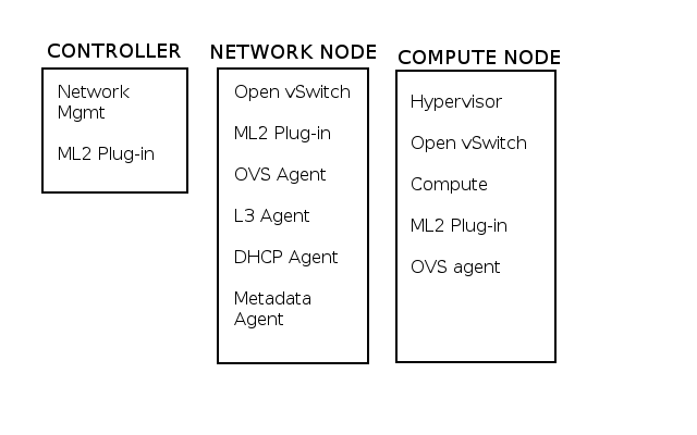
Service OpenStack

The number and type of interfaces depend on how good you feel about combining control and data traffic. Networking can function with just one interface, but splitting the different kinds of network traffic into several separate interfaces is good.

OpenStack Network Types uses four types of traffic – Management, API, External, and Guest. If you are going to separate anything, it’s recommended to physically separate management and API traffic from all other types of traffic. Separating the traffic to different interfaces splits the control from data traffic—a tick from the security auditors’ box.
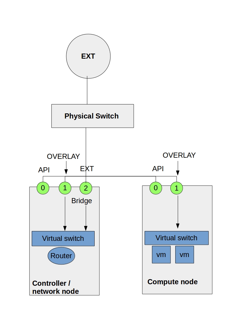
Neutron Reference Design

The preceding diagram, Eth0 is used for the management and API network, Eth1 for overlay traffic, and Eth2 for external and Tenant networks ( depending on the host ). The tenant networks ( Eth2 ) reside on the compute nodes, and the external network resides on the controller node ( Eth2 ).

The controller Eth2 interface uses Neutron routers for external network traffic to instances. In certain Neutron Distributed Virtual Routing ( DVR ) scenarios, the external networks are at the compute nodes.

Plugins and drivers

Neutron networking operates with the concept of plugins and drivers. Neutrons core plugin can be either an ML2 or a vendor plugin. Before ML2, Neutron was limited to a single-core plugin at any given time. The ML2 plugin introduces the concept of type and mechanism drivers.

Type drivers represent type-specific network states and support local, flat, vlan, gre, and vxlan network types. Mechanism drivers take information from the type driver and ensure its implementation correctly.

There are agent-based, controller-based, and Top-of-Rack models of the mechanism driver. The most popular are the L2 population, Open vSwitch, and Linux bridge. In addition, the mechanism driver arena is a popular space for vendors’ products.

Linux Namespaces

The majority of environments require some multi-tenancy. Cloud environments would be straightforward if built for only one customer or department. In reality, this is never the case. Multi-tenancy within Neutron is based on Linux Namespaces. Namespace offers a completely isolated stack to do what you want. They enable a logical copy of the network stack supporting overlapping IP assignments.

A lot of Neutron networking is made possible with the use of namespaces and the ability to connect them.

We have a qdhcp namespace, qrouter namespace, qlbass namespace, and additional namespaces for DVR functionality. Namespaces are present on nodes running the respective agents. The following command displays different routing tables for NAMESPACE-A and the global namespace, illustrating the ability of network stack isolation.
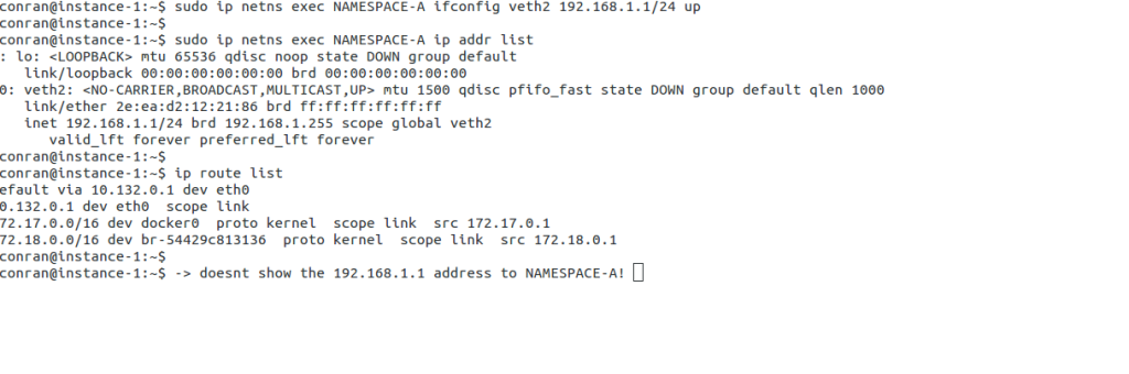
Linux namespace

OpenStack Network Types: Virtual network infrastructure

Local, Flat, VLAN, VXLAN, and GRE networks

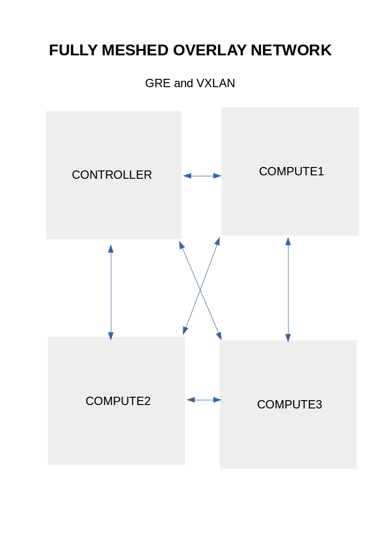
Neutron networking supports Local, Flat, VLAN, VXLAN, and GRE networks. Local networks are isolated networks. Flat networks do not incorporate any VLAN tagging. On the other hand, VLAN networks use the standard. Q tagging ( IEEE 802.1Q ) to segregate traffic. VXLAN networks encapsulate Layer 2 traffic over IP using VTEP and VXLAN network identifier ( VNI ).

GRE is another type of Layer 2 over Layer 3 overlay. Both GRE and VXLAN accomplish the same goal of emulation over pure IP but use different methods —VXLAN traffic uses UDP, and GRE traffic uses IP protocol 47.

Layer 2 data is transported from an end host, encapsulated over IP to the egress switch that sends the data to the destination host. With an underlay and overlay approach, you have two layers to debug when something goes wrong.
openstack network types

OpenStack Network Types: Virtual Network Switches

The first step in building a virtual network is to make the virtual switching infrastructure. This acts as the base for any network design, whether virtual or physical. Virtual switching provides connectivity to and from the virtual instances, building the concrete for advanced networking services. The first piece of the puzzle is the virtual network switches.

Neutron networking includes built-in support for the Linux Bridge and Open vSwitch. Both are virtual switches but operate with some significant differences. The Linux bridge uses VLANs to tag traffic, while the Open vSwitch uses flow rules to manipulate traffic before forwarding.

Instead of mapping the local VLAN ID to a physical VLAN ID, the local ID is added or stripped from the Ethernet header by flow rules.

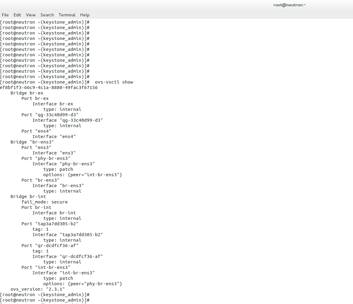
The “brctl show” command displays the Linux bridge. The bridge ID is automatically generated based on the NIC, and the bridge name is based on the UUID of the corresponding Neutron network. The “ovs-vsctl show” command displays the Open vSwtich. It has a slightly more complicated setup, with the br-int ( integration bridge ) acting as the main center point of connections.

openstack network types

Neutron uses the bridge, 802.1q, and vxlan kernel modules to connect instances with the Linux bridge. Bridge and Open vSwitch kernel modules are used for the Open vSwitch. The Open vSwitch uses some userspace utilities to manage the OVS database. Most networking elements are connected with virtual cables, known as veth cables. What goes in one end must come out; the other best describes a virtual cable.

Veths connect many elements, including namespace to the namespace, Open vSwitch to Linux bridge, and Linux bridge to Linux bridge, all combined with veth cables. The Open vSwitch uses additional particular patch ports to connect Open vSwitch bridges. The Linux bridge doesn’t use patch ports.

The Linux Bridge and Open vSwitch can complement each other. For example, when Neutron Security Groups are enabled, instances connect to the Linux and Open vSwitch Integration bridges with a Veth cable. The workaround is caused by the inability to place IPtable rules ( needed by security groups ) on tap interfaces connected to Open vSwitch bridge ports. 

Neutron network and network address translation (NAT)

Neutron employs the concept of Network Address Translation (NAT) to predict inbound and outbound translations. The concept of NAT stays the same in the virtual world, either by modifying an IP packet’s source or destination address. Neutron employs two types of translations – one-to-one and one-to-many.

One-to-one translations utilize floating IP addresses, and many-to-one is a Port Address Translation ( PAT ) style design where floating IP is not used. F

Floating IP addresses are externally routed IP addresses that directly map instances and an external IP address. The term floating comes from the fact that they can be modified on-the-fly between instances. They are associated with a Neutron port logically mapped to an example. Ports can have multiple IP addresses assigned.

    • SNAT refers to source NAT, which changes the source IP address to appear as the externally connected interface.
    • Floating IPs are called Destination NAT ( DNAT ), which change the source and destination IP address depending on traffic direction.

The external network connected to the virtual router is the network from which floating IPs are derived. The default behavior is to source NAT traffic from instances that lack floating IP. Instances that use source NAT can not accept traffic initiated externally. If you want traffic created externally to hit an instance, you must use a one-to-one mapping with a floating IP.

Neutron High Availability

Standalone router

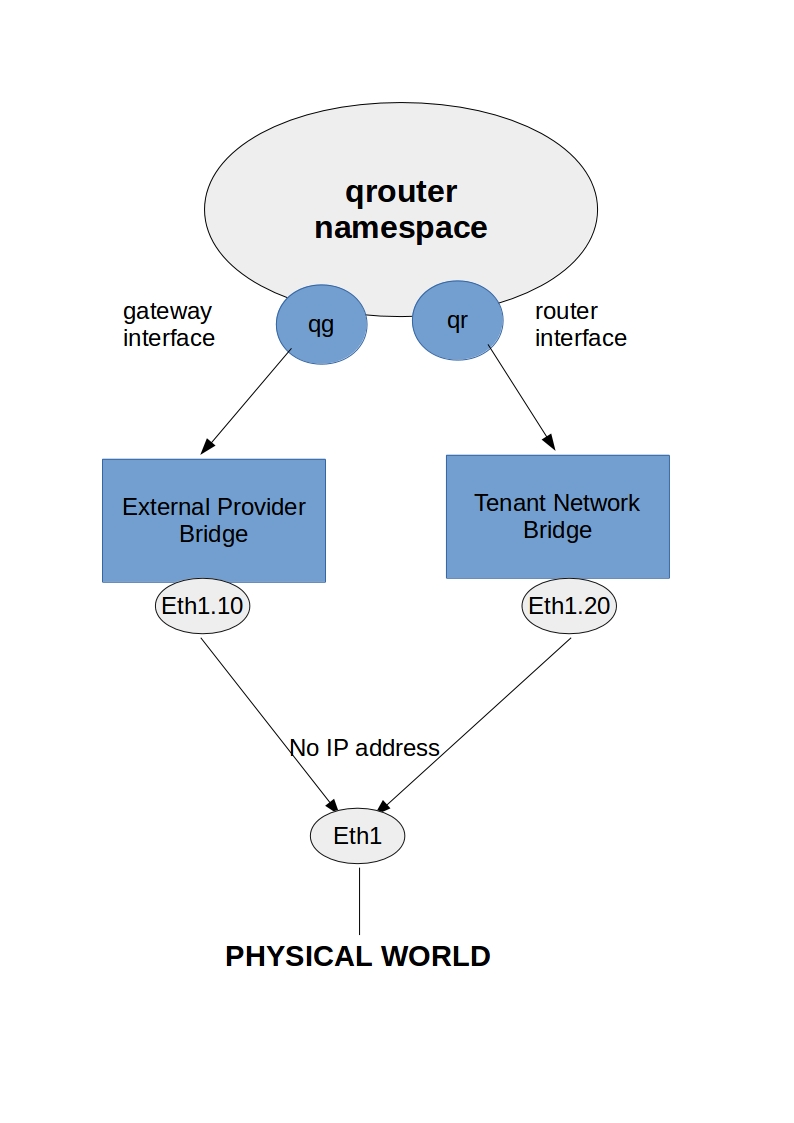
The most accessible type of router to create in Neutron is a standalone router. As the name suggests, it lacks high availability. Routers created with Neutron exist on namespaces that reside on the nodes running the L3 agent. It is the role of the Layer 3 agent to create the network namespace representing the routing function.

A virtual router is essentially a network namespace called the qrouter namespace. The qrouter namespace uses routing tables to forward traffic and IPtable rules to dictate how traffic is translated.
neutron networking

A virtual router can connect to two different types of networks: a single external provider network or one or more tenant networks. The interface to an external provider bridge network is “qg,” and to a tenant network bridge is a “qr” interface. The tenant network traffic is routed from the “qr” interface to the “qg” interface for onward external forwarding.

Virtual router redundancy protocol

VRRP is pretty simple and offers highly available and redundant default gateways or the next hop of a route. The namespaces ( routers ) are spread across multiple hosts running the Layer 3 agent. Multiple router namespaces are created and distributed among the Layer 3 agents. VRRP operates with a Linux keepalive instance. Each runs a “keepalive” service to detect the other’s availability.

The keepalive service is a Linux keepalive tool that uses VRRP internally. It is the role of the L3 agent to start the keepalive instance on every namespace. A dedicated HA network allows the routers to talk to each other. There are split-brain and MAC flapping issues; as far as I understand, it’s still an experimental feature. 

Distributed virtual routing 

DVR eliminates the bottleneck caused by the Layer 3 agent and distributes most of the routing function across multiple compute nodes. This helps isolate failure domains and increases the high availability of the virtual network infrastructure. With DVR, the routing function is not centralized anymore but decentralized to the compute nodes. The compute nodes themselves become one big router.

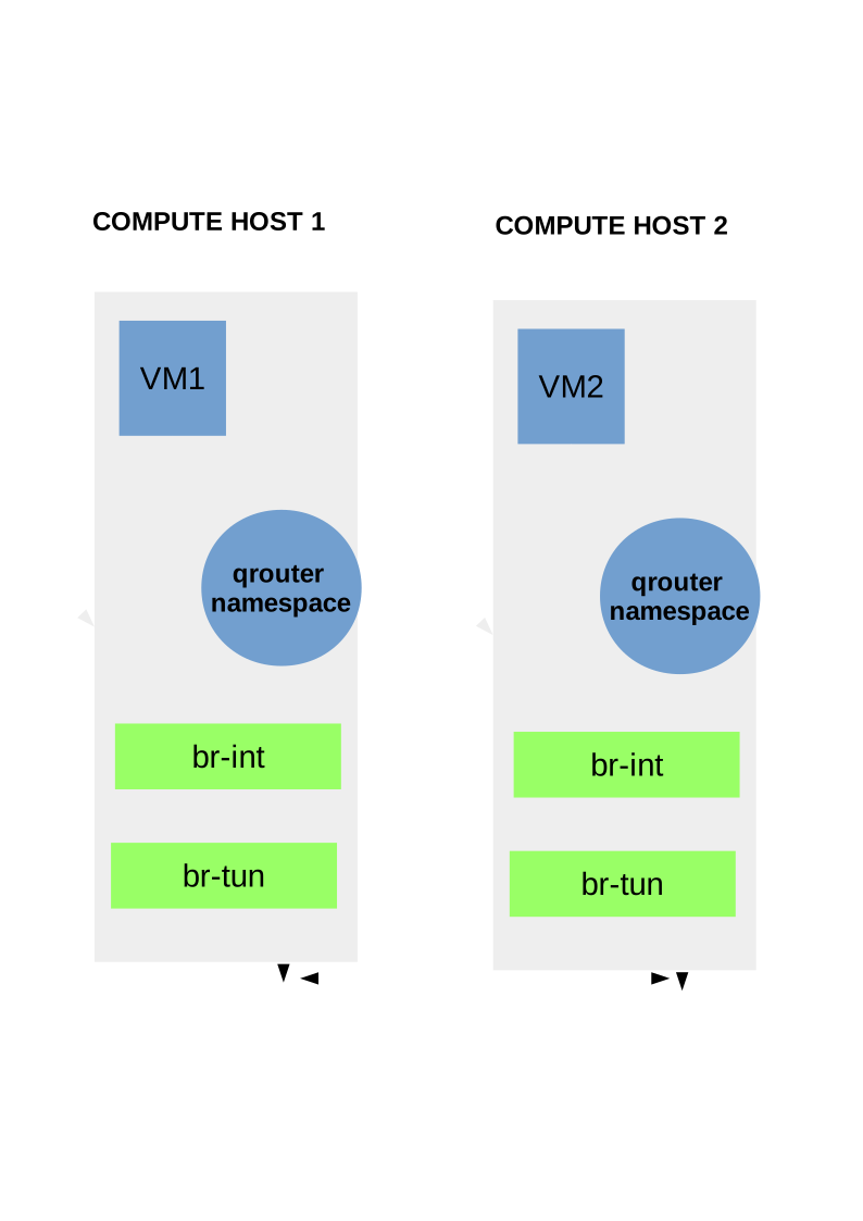
DVR routers are spawned on the compute nodes, and all the routing gets done closer to the workload. Distributing routing to the compute nodes is much better than having a central element perform the routing function.

There are two types of modes: dvr and dvr_snat. Mode dvr_snat handles north-to-south SNAT traffic. Mode DVR handles north-to-south DNAT traffic ( floating IP) and all east-to-west traffic.

Key Points:

  • East-West traffic ( server to server ) previously went through the centralized network node. DVR pushes this down to the compute nodes hosting the VMs.
  • North-South traffic with floating IPs ( DNAT ) is routed directly by the compute nodes hosting the VMs.
  • North-South traffic without floating IP ( SNAT ) is routed through a central network node. Distributing the SNAT functions to the local compute nodes can be complicated.
  • DNAT is required to compute nodes using floating IPs that require direct external connectivity.

East-west traffic between instances

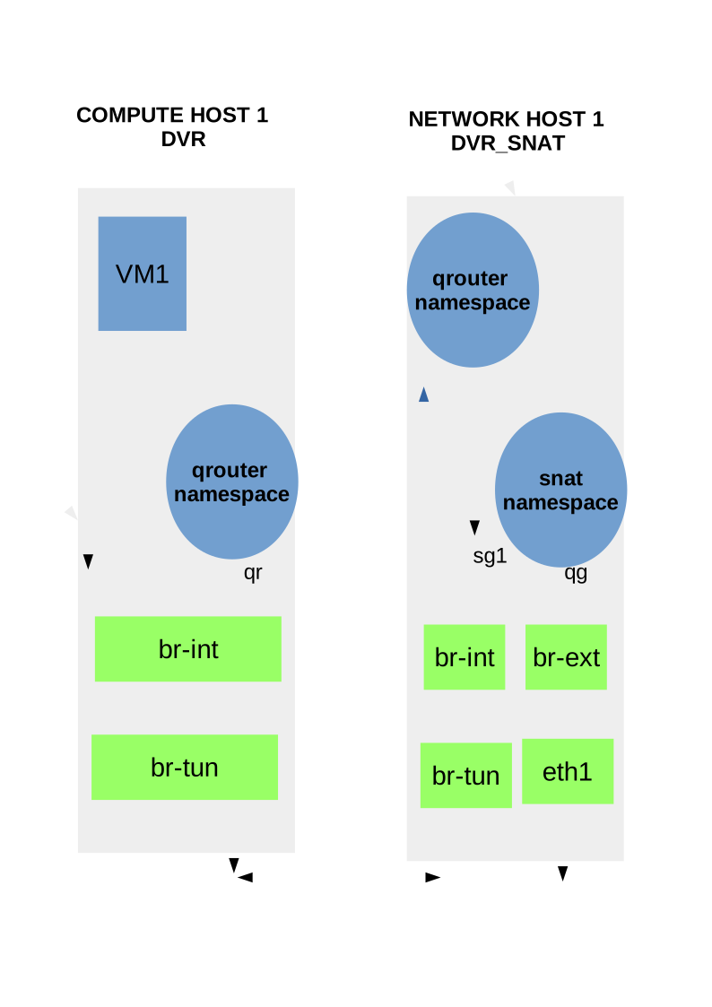
East-to-west traffic (traditional server-to-server) refers to local communication, such as traffic between a frontend and the backend application tier. DVR enables each compute node to host a copy of the same router. The router namespace created on each compute node has the same interface, MAC, and IP settings.

East West traffic

DVR East to WestNEWDVR East to West

The qr interfaces within the namespaces on each compute node share the same IP and MAC address. But how is this possible?? One can assume the distribution of ports would raise IP clashes and MAC flapping. Neutron cleverly uses routing tables and Open vSwitch flow rules to enable this type of forbidden sharing.

Neutron allocates each compute node a unique MAC address, which is used whenever traffic leaves the node.

Once traffic leaves the virtual router, Open vSwitch rules rewrite the source MAC address with the unique MAC address allocated to the source node. All the manipulation is done before and after traffic leaves or enters, so the VM is unaware of any rewriting and operates as usual.

Centralized SNAT 

Source SNAT is used when instances do not have a floating IP address. Neutron decided not to distribute SNAT to the compute nodes and kept it central, similar to the legacy model. Why did they decide to do this when DVR distributes floating IP for north-south traffic?

Decentralizing SNAT would require an address from the external network on every node providing the SNAT service. This would consume a lot of addresses on your external network.
centralized SNAT

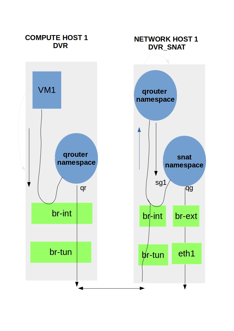
The Layer 3 agent configured as dvr_snat server is the centralized SNAT function. Two namespaces are created for the same router—a regular qrouter namespace and an SNAT namespace. The SNAT and qrouter namespaces are created on the centralized nodes, either the controller or the network node.

The qrouter namespaces on the controller and compute nodes are identical. However, even though the router is attached to an external network, there are no qg interfaces. The qg interfaces are now inside the SNAT namespace. There is also now a new interface called the sg. This is used as an extra hop.


Packet Flow

  • A VM without a floating IP sends a packet to an external destination.
  • Traffic arrives at the regular qrouter namespace on the actual node and gets redirected to the SNAT namespace on the central node.
  • To redirect traffic from the qrouter namespace to the SNAT namespace is carried out by clever tricks with source routing and multiple routing tables.

 North-to-south traffic with Neutron floating IP

In the legacy world, floating IPs are configured as /32 prefixes on the router’s external device. The one-to-one mapping between the VM IP address and the floating IP address is used so external devices can initiate external traffic to the internal instance.

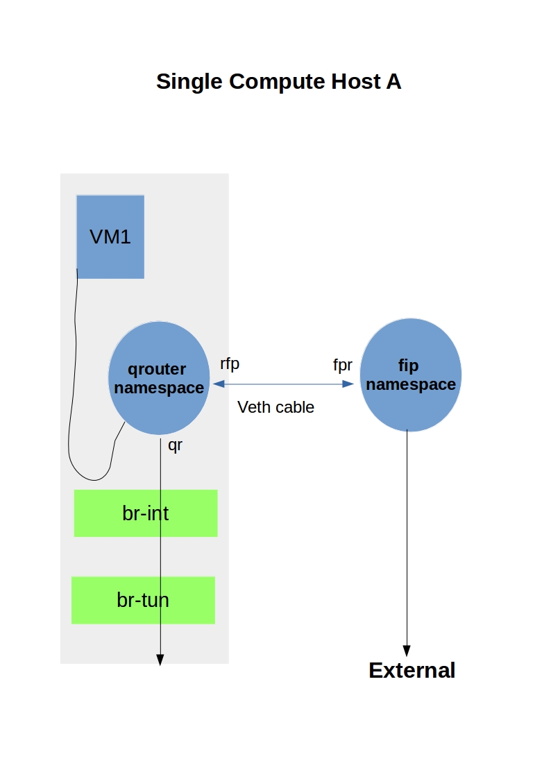
North-to-south traffic with floating IP is now handled with another namespace called the fip namespace. The new fip namespace is created by the Layer 3 agent and represents the external network to which the fip belongs.
distributed virtual routing

Every router on the compute node is hooked into the new fip namespace with a veth pair. Veth pairs are commonly used to connect namespaces. One side of the other pair is in the router namespace (rfp), and the other end belongs to the fip namespace (fpr).

Whenever a layer 3 agent creates a new floating IP, a new rule is specific to that IP. Neutron adds the fixed IP of the VM to the rules table with an additional new routing table.

Packet Flow

  • When a VM with a floating IP sends traffic to an external destination, it arrives at the qrouter namespace.
  • The IP rules are consulted, showing a default route for that source to the next hop. IPtables rules kick in, and the source IP is translated to the floating IP.
  • Traffic is forwarded out the rfp interface and arrives at the fpr interface at the fip namespace.
  • The fip namespace uses a default route to forward traffic out the ‘fg’ device to its external destination.

Traffic in the reverse direction requires Proxy ARP, so the fip namespace answers requests for the floating IP configured on the router’s router namespace ( not the fip namespace ). In addition, proxy ARP enables hosts ( fip namespace) to answer ARP requests intended for other hosts ( qrouter namespace ).

Closing Points on Neutron Networking

Neutron is built on a modular architecture that allows for easy integration and customization. At its core, Neutron consists of several components, including the Neutron server, plugins, agents, and a database. The Neutron server handles API requests and manages network states, while plugins and agents manage network configurations on physical devices. This modular design ensures that Neutron can be extended to support new networking technologies and adapt to evolving industry standards.

Neutron offers a wide array of features that empower users to build complex network topologies. Some of the key features include:

– **Network Segmentation**: Neutron supports VLAN, VXLAN, and GRE tunneling technologies, enabling efficient network segmentation and isolation.

– **Load Balancing**: With Neutron, users can deploy load balancers as a service to distribute incoming network traffic across multiple servers, enhancing application availability and reliability.

– **Security Groups**: Neutron’s security groups allow users to define network access control policies, providing an additional layer of security for cloud applications.

– **Floating IPs**: These enable dynamic IP allocation, allowing instances to be accessed from external networks, which is crucial for public-facing applications.

Neutron is seamlessly integrated with other OpenStack services, making it an indispensable part of the OpenStack ecosystem. It works in tandem with Nova, the compute service, to ensure that network resources are allocated efficiently to virtual instances. Neutron also collaborates with Cinder, the block storage service, to provide persistent storage solutions. This integration ensures a cohesive cloud environment where networking, compute, and storage components work harmoniously.
 

OpenStack Neutron · Troubleshooting Challenge

Why Can't This VM Reach the Internet?

A tenant VM can communicate with other workloads on its private network, but an outbound connection to the external network fails. Inspect the logical path and identify the Neutron component that should provide the missing Layer 3 connectivity.

Incident Scenario

web-01 has IP address 10.20.1.15. It can reach another VM on the same tenant network, so the local network and port are functioning. However, an outbound request to 8.8.8.8 fails. There is no floating IP assigned to web-01. The security policy permits outbound traffic.

What should you investigate first?

Current Logical Path
web-01 10.20.1.15
Tenant VM
Neutron Port MAC + IP
Logical attachment
Virtual Router Layer 3
Tenant gateway
External Network Provider / Internet
8.8.8.8
Choose Your Diagnosis
Challenge Score
0/1
Select the most likely fault domain.
Packet Investigation
incident: outbound connectivity failure
source: 10.20.1.15
destination: 8.8.8.8
local tenant connectivity: OK
floating IP: not assigned
security policy: outbound permitted
status: investigation required...
Engineer Hint
Start at the point where the traffic leaves the tenant network. A VM without a floating IP can still have outbound connectivity, but the design needs an appropriate external routing and SNAT path.
Computer case

Openstack Neutron Security Groups

OpenStack Neutron Security Groups

OpenStack Neutron Security Groups provide a virtual network security control for workloads connected to OpenStack networks. They apply traffic rules to virtual ports and can control which connections are permitted to and from instances and other resources.

A security group can be thought of as a distributed, policy-based firewall associated with one or more Neutron ports. Instead of placing a separate physical firewall in front of every workload, security policies can be applied close to the virtual network interface where the workload connects to the cloud network.

Security group rules commonly define traffic using attributes such as direction, protocol, port or port range, and remote IP address or security group. This allows administrators to express policies such as permitting HTTPS traffic to a web tier, allowing database connections only from an application tier, or restricting administrative access to specific management networks.

Security groups are associated with Neutron ports rather than being purely an instance-level concept. This is important because a virtual machine can have multiple network interfaces, and each interface can have its own networking and security context. The resulting policy is therefore applied at the virtual network attachment point.

Security groups are commonly used as a stateful security mechanism. For permitted connections, the return traffic is handled as part of the connection state rather than requiring administrators to manually create an independent rule for every response packet. The exact implementation depends on the Neutron networking backend.

A typical application architecture might therefore use separate security policies for web, application and database tiers. Public-facing interfaces may permit HTTPS, application interfaces may accept traffic only from the web tier, and database interfaces may permit connections only from designated application workloads. This creates segmentation without requiring every traffic decision to be implemented through a central physical firewall.

Effective rule design is more important than simply creating a large number of rules. Broad rules such as allowing all protocols from all addresses increase the attack surface and make the security policy difficult to understand and audit. Rules should instead be based on clearly defined application and operational requirements.

A useful principle is least privilege: permit the smallest set of traffic required for the workload to operate. Where appropriate, use restricted source networks or security groups rather than broad address ranges, and avoid exposing management services unnecessarily.

Security groups should also be reviewed as part of the wider cloud security lifecycle. Unused rules, obsolete workloads and temporary exceptions can accumulate over time. Regular auditing helps identify unnecessary access and keeps the effective security policy aligned with the intended architecture.

It is also important to understand what security groups do not provide. They are not a complete replacement for network firewalls, application-layer security controls, identity systems, vulnerability management or host-based security. Security groups operate primarily at the virtual network access-control layer and should form part of a defence-in-depth architecture.

Integration with the wider OpenStack environment is therefore important. Keystone provides identity and authentication services, while Neutron provides the networking model and ports to which security policies are applied. The underlying networking implementation then enforces those policies in the virtual data plane.

Troubleshooting security groups requires following the actual packet path. Engineers may need to examine the instance interface, Neutron port, applied security groups, rule direction, protocol and port, source and destination addressing, routing, network namespaces, virtual switching, overlay connectivity and any additional firewall controls. A packet being blocked does not necessarily mean the security-group rule itself is the only possible cause.

For OpenStack engineers, the key concept is that Neutron Security Groups provide distributed, policy-based traffic control at the virtual network edge. When combined with least-privilege rules, segmentation, identity controls, host security and appropriate network firewalls, they form an important layer of defence for cloud workloads.

OpenStack Neutron · Security Groups

How a Security Group Evaluates Traffic

Select a traffic flow and see how a Neutron security-group policy is evaluated at the workload's network port.

PORT-LEVEL POLICY
Traffic Evaluation Path Inbound request
◉
Internet External source
→
⌁
Neutron Port Attached to workload
→
◆
Security Group Rule evaluation
→
▣
Web Server Application endpoint
Security Group: web-tier Illustrative policy
INBOUND RULES
TCP 443 Source: Internet
ALLOW
TCP 80 Source: Internet
ALLOW
TCP 22 Source: Trusted Admin Subnet
ALLOW
All other inbound traffic No matching allow rule
DENY
OUTBOUND POLICY
Any protocol / destination Web tier egress policy
ALLOW
Evaluation Result READY
?
Ready to evaluate Configure the traffic flow, then run the security-group evaluation.
Port —
Rule Match —
Decision —
Exposure —
Networking Insight Security groups are a policy layer associated with network ports. The exact enforcement mechanism depends on the Neutron deployment.
Evaluation Console LIVE TRACE
[00:00] Security group web-tier attached.
[00:00] Waiting for traffic evaluation...
Conceptual simulation for learning. It illustrates the security-group decision process rather than a specific Neutron backend implementation.

Highlights: OpenStack Neutron Security Groups

What is OpenStack Neutron?

OpenStack Neutron is a networking service that provides on-demand network connectivity for cloud-based applications and services. It acts as a virtual network infrastructure-as-a-service (IaaS) platform, allowing users to create and manage networks, routers, subnets, and more. By abstracting the underlying network infrastructure, Neutron provides flexibility and agility in managing network resources within an OpenStack cloud environment.

OpenStack Neutron offers a wide range of features that empower users to build and manage complex network topologies. Some of the key features include:

1. Network Abstraction: Neutron allows users to create and manage virtual networks, enabling multi-tenancy and isolation between different projects or tenants.

2. Routing and Load Balancing: Neutron provides routing functionalities, allowing traffic to flow between different networks. It also supports load balancing services, distributing traffic across multiple instances for improved performance and reliability.

3. Security Groups: With Neutron, users can define security groups that act as virtual firewalls, controlling inbound and outbound traffic for instances. This enhances the security posture of cloud-based applications.

Neutron Security Groups

Neutron Security Groups serve as virtual firewalls, controlling inbound and outbound traffic to instances within an OpenStack cloud environment. They allow administrators to define and manage firewall rules, thereby enhancing the overall security posture of the network. By grouping instances with similar security requirements, Neutron Security Groups simplify the management of network access policies.

Implementing Security Groups:

To configure Neutron Security Groups, start by creating a security group and defining its rules. These rules can specify protocols, ports, and IP ranges for both inbound and outbound traffic. By carefully crafting these rules, administrators can enforce granular security policies and restrict access to specific resources or services.

Once Neutron Security Groups are configured, they can be easily applied to instances within the OpenStack cloud. By associating instances with specific security groups, administrators can ensure that only authorized traffic is allowed to reach them. This provides an additional layer of protection against potential threats and unauthorized access attempts.

Security Groups Advanced Features:

Neutron Security Groups offer advanced features that further enhance network security. These include the ability to define security group rules based on source and destination IP addresses, as well as the option to apply security groups at the port level. Additionally, Neutron Security Groups support the use of security group logging and can integrate with other OpenStack networking services for seamless security management.

Best Practices:

To maximize the effectiveness of Neutron Security Groups, it is crucial to follow certain best practices. Firstly, adopting a least-privilege approach is recommended, ensuring that only necessary ports and protocols are allowed. Regularly reviewing and updating the security rules is also vital to maintain an up-to-date and secure environment. Additionally, leveraging security groups in conjunction with other OpenStack security features, such as firewalls and intrusion detection systems, can provide a multi-layered defense strategy.

Virtual Networks

A monolithic plugin configured the virtual network in the early days of OpenStack Neutron (formerly known as Quantum). As a result, virtual networks could not be created using gear from multiple vendors. Even when single network vendor devices were used, virtual switches or virtual network types could not be selected. Prior to the Havana release, the Linux bridge and OpenvSwitch plugins could not be used simultaneously. As a result of the creation of the ML2 plugin, this limitation has been addressed

**Open vSwitch & Linux Bridge**

Both OVS and Linux bridge-based virtual switch configurations are supported by ML2 plugins. For network segmentation, it also supports VLANs, VXLANs, and GRE tunnels. In addition to writing drivers, it allows you to implement new types of networks. ML2 drivers fall into two categories: type drivers and mechanism drivers. The type drivers implement the network isolation types VLAN, VXLAN, and GRE. Mechanism drivers implement mechanisms for orchestrating physical or virtual switches:

With OpenStack, virtual networks are protected by network security.A virtual network’s security policies can be self-serviced, just like other network services.Using security groups, firewalls provide security services at the network boundary or at the port level.

Incoming and outgoing traffic are subject to security rules based on match conditions, which include:

  • Source and destination addresses should be subject to security policies
  • Source and destination ports of network flows
  • Traffic direction, egress/ingress

**Security groups**

Network access rules can be configured at the port level with Neutron security groups. Tenants can set access policies for resources within the virtual network using security groups. IPtables uses security groups to filter traffic.

**Network-as-a-Service**

The power of open-source cloud environments is driven by Liberty OpenStack and the Neutron networks forming network-as-a-service. OpenStack can now be used with many advanced technologies – Kubernetes network namespace, Clustering, and Docker Container Networking. By default, Neutron handles all the networking aspects for OpenStack cloud deployments and allows the creation of network objects such as routers, subnets, and ports.

For example, Neutron creates three subnets and defines the conditions for tier interaction with a standard multi-tier application with a front, middle, and backend tier. The filtering is done centrally or distributed with tenant-level firewall OpenStack security groups.

**OpenStack is Modular**

OpenStack is very modular, which allows it to be enhanced by commercial and open-source network technologies. The plugin architecture allows different vendors to strengthen networking and security with advanced routers, switches, and SDN controllers. Every OpenStack component manages a resource made available and virtualized to the user as a consumable service, creating a network or permitting traffic with ingress/egress rule chains. Everything is done in software – a powerful abstraction for cloud environments.


OpenStack Neutron · Policy Design Lab

Build a Least-Privilege Security Group

Start with a small rule set, add only the flows the application needs, then test the resulting policy against realistic traffic.

DESIGN · TEST · HARDEN
Security Group Rule Builder 0 rules
Application Traffic Model Frontend → App → Database
◎
Frontend Web tier
→
◆
Application API tier
→
▣
Database Data tier
Policy Rules 0
Allowed Flows 0 / 4
Unnecessary Exposure Unknown
Posture Not tested
Policy Assessment READY
Least-Privilege Score —
Build your policy, then test the application flows.
Security Event Console LIVE
[00:00] Policy builder ready.
[00:00] Add only required application flows.
Engineering Insight Least privilege is not simply “deny everything”. The useful policy is the smallest rule set that permits the required application behaviour.
Conceptual learning simulation. Neutron security-group enforcement can vary with the networking backend and deployment architecture.

OpenStack Neutron Security Groups

Security Groups

Security groups are essential for maintaining access to instances. They permit users to create inbound and outbound rules that restrict traffic to and from models based on specific addresses, ports, protocols, and even other security groups.

Neutron creates default security groups for every project, allowing all outbound communication and restricting inbound communication to instances in the same default security group. Following security groups are locked down even further, allowing only outbound communication and not allowing any inbound traffic at all unless modified by the user.

Benefits of OpenStack Neutron Security Groups:

1. Granular Control: With OpenStack Neutron Security Groups, administrators can define specific rules to control traffic flow at the instance level. This granular control enables the implementation of stricter security measures, ensuring that only authorized traffic is allowed.

2. Enhanced Security: By utilizing OpenStack Neutron Security Groups, organizations can strengthen the security posture of their cloud environments. Security Groups help mitigate risks by preventing unauthorized access, reducing the surface area for potential attacks, and minimizing the impact of security breaches.

3. Simplified Management: OpenStack Neutron Security Groups offer a centralized approach to managing network security. Administrators can define and manage security rules across multiple instances, making it easier to enforce consistent security policies throughout the cloud infrastructure.

4. Dynamic Adaptability: OpenStack Neutron Security Groups allow dynamic adaptation to changing network requirements. As instances are created or terminated, security rules can be automatically applied or removed, ensuring that security policies remain up-to-date and aligned with the evolving infrastructure.

Security Group Implementation Example:

To illustrate the practical implementation of OpenStack Neutron Security Groups, let’s consider a scenario where an organization wants to deploy a multi-tier web application in its OpenStack cloud. They can create separate security groups for each tier, such as web servers, application servers, and database servers, with specific access rules for each group. This segregation ensures that traffic is restricted to only the necessary ports and protocols, reducing the attack surface and enhancing overall security.

OpenStack Neutron Security Groups: The Components

Control, Network, and Compute

The OpenStack architecture for network-as-a-service Neutron-based clouds is divided into Control, Network, and Compute components. At a very high level, the control tier runs the Application Programming Interfaces (API), compute is the actual hypervisor with various agents, and the network component provides network service control.

All these components use a database and message bus. Examples of databases include MySQL, PostgreSQL, and MariaDB; for message buses, we have RabbitMQ and Qpid. The default plugins are Modular Layer 2 (ML2) and Open vSwitch. 

Openstack Neutron Security Groups

Ports, Networks, and Subnets

Neutrons’ network-as-a-service core and the base for the API are elementary. It consists of Ports, Networks, and Subnets. Ports hold the IP and MAC address and define how a VM connects to the network. They are an abstraction for VM connectivity.

A network is a Layer 2 broadcast domain represented as an external network (reachable from the Internet), provider network (mapped to an existing network), and tenant network, created by cloud users and isolated from other tenant networks. Layer 3 routers connect networks; subnets are the subnet spaces attached to networks. 

OpenStack Neutron: Components

OpenStack networking with Neutron provides an API to create various network objects. This powerful abstraction allows the creation of networks in software and the ability to attach multiple subnets to a single network. The Neutron Network is isolated or connected with Layer 3 routers for inter-network connectivity.

Neutron employs floating IP, best understood as a 1:1 NAT translation. The term “floating” comes from the fact that it can be modified on the fly between instances.

It may seem that floating IPs are assigned to instances, but they are actually assigned to ports. Everything gets assigned to ports—fixed IPs, Security Groups, and MAC addresses. SNAT (source NAT) or DNAT (destination NAT) enables inbound and outbound traffic to and from tenants. DNAT modifies the destination’s IP address in the IP packet header, and SNAT modifies the sender’s IP address in IP packets. 

Open vSwitch and the Linux bridge

Neutrons can be integrated for switching functionality with Open vSwitch and Linux bridge. By default, it integrates with the ML2 plugin and Open vSwitch. Open vSwitch and Linux bridges are virtual switches orchestrating the network infrastructure.

For enhanced networking, the virtual switch can be controlled outside Neutron by third-party network products and SDN controllers via plugins. The Open vSwitch may also be replaced or used in parallel. Recently, many enhancements have been made to classic forwarding with Open vSwitch and Linux Bridge.

We now have numerous high availability options with L3 High Availability & VRRP and Distributed Virtual Routing (DVR) feature. DVR essentially moves to route from the Layer 3 agent to compute nodes. However, it only works with tunnels and L2pop enabled, requiring the compute nodes to have external network connectivity.

For production environments, these HA features are a welcomed update. The following shows three bridges created in Open vSwitch – br-ex, br-ens3, and br-int. The br-int is the main integration bridge; all others connect via particular patch ports.

Openstack Neutron Security Groups

Network-as-a-service and agents

Neutron has several parts backed by a relationship database. The Neutron server is the API, and the RPC service talks to the agents (L2 agent, L3 agent, DHCP agent, etc.) via the message queue. The Layer 2 agent runs on the compute and communicates with the Neutron server with RPC. Some deployments don’t have an L2 agent, for example, if you are using an SDN controller.

Also, if you deploy the Linux bridge instead of the Open vSwitch, you don’t have the Open vSwitch agent; instead, use the standard Linux Bridge utilities. The Layer 3 agent runs on the Neutron network node and uses Linux namespaces to implement multiple copies of the IP stack. It also runs the metadata agent and supports static routing. 

Linux Namespaces

An integral part of Neutron networking is the Linux namespace for object isolation. Namespaces enable multi-tenancy and allow overlapping IP address assignment for tenants – an essential requirement for many cloud environments. Every network and network service a user creates is a namespace.

For example, the qdhcp namespace represents the DHCP services, qrouter namespace represents the router namespace and the qlbaas represents the load balance service based on HAProxy. The qrouter namespaces provide routing amongst networks – north-south and east-west traffic. It also performs SNAT and DNAT in classic non-DVR scenarios. For certain cases with DVR, the snat namespaces perform SNAT for north-south network traffic.

 OpenStack Neutron Security Groups

OpenStack has the concept of OpenStack Neutron Security Groups. They are a tenant-level firewall enabling Neutron to provide distributed security filtering. Due to the limitations of Open vSwitch and iptables, the Linux bridge controls the security groups. Neutron security groups are not directly added to the Integration bridge. Instead, they are implemented on the Linux bridge that connects to the integrated bridge.

The reliance on the Linux bridge stems from Neutron’s inability to place iptable rules on tap interfaces connected to the Open vSwitch. Once a Security Group has been applied to the Neutron port, the rules are translated into iptable rules, which are then applied to the node hosting the respective instance.

Neutron also can protect instances with perimeter firewalls, known as Firewall-as-a-service.

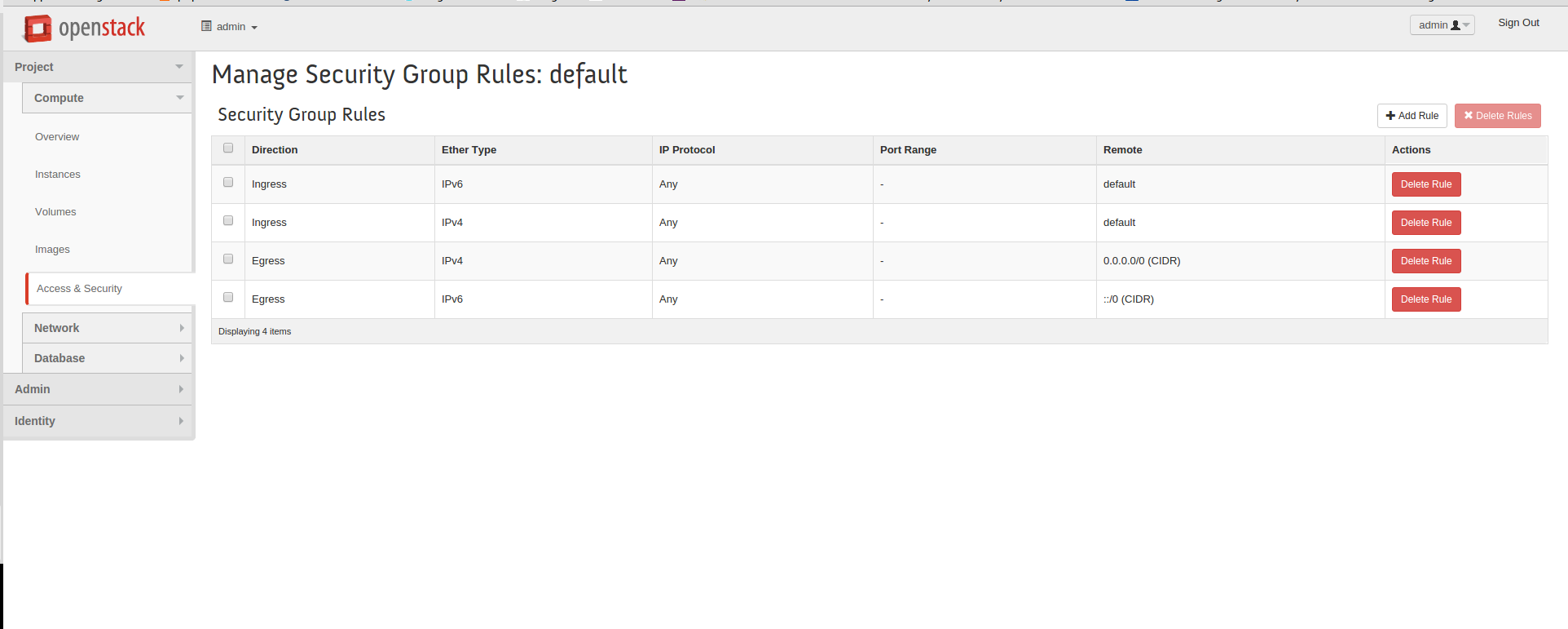
Firewall rules implemented with perimeter firewalls utilizing iptables within a Neutron routers namespace instead of configuring on every compute host. The following diagram displays ingress and egress rules for the default security group. Tenants that don’t have a security group are placed in the default security group.


Openstack Neutron Security Groups

Closing Points on OpenStack Neutron Security Groups

In the realm of cloud computing, security is paramount. OpenStack, a popular open-source cloud platform, offers various components to ensure robust security within its environment. One of the core elements of this security architecture is Neutron Security Groups. These act as virtual firewalls, providing a layer of protection for instances by controlling inbound and outbound traffic at the network interface level. But what exactly are Neutron Security Groups, and how do they function?

Neutron Security Groups in OpenStack are designed to enhance the security of your cloud infrastructure. They are essentially sets of IP filter rules that define networking access to the instances. Each instance can be associated with one or more security groups, and each group contains a collection of rules that specify the type of traffic allowed to and from instances.

These rules are based on IP protocols, source, and destination IP ranges, and port numbers. By default, a security group allows all outbound traffic and denies all inbound traffic. Users can then customize the rules to fit their specific security needs, providing a flexible and dynamic security solution.

To effectively use Neutron Security Groups, one must understand how to create and manage them within the OpenStack environment. Creating a security group involves defining a set of rules that determine the traffic allowed to reach the associated instances. This is done through the Horizon dashboard or OpenStack CLI, where users can specify the security protocols and port ranges.

Managing these groups involves regularly updating the rules to adapt to changing security requirements. This might include adding new rules, modifying existing ones, or deleting those that are no longer necessary. Effective management ensures that the cloud environment remains secure while allowing necessary traffic to pass through.

Implementing best practices when using Neutron Security Groups can significantly enhance your cloud’s security posture. First, it’s crucial to follow the principle of least privilege, allowing only the necessary traffic to and from your instances. Regular audits of security group rules help identify and eliminate redundancies or outdated rules that might expose vulnerabilities.

Additionally, documenting each rule’s purpose and the rationale behind it can aid in maintaining a clear security strategy. It’s also advisable to automate security group updates and monitoring using tools and scripts, ensuring real-time responsiveness to potential threats.

OpenStack Neutron · Incident Investigation

Why Can't the Application Reach the Database?

Use the evidence to identify the security-group fault. Think like an engineer: follow the traffic path before changing infrastructure.

INCIDENT · DIAGNOSE
Incident Evidence PRODUCTION ALERT
!
api-01 cannot connect to db-01 The application tier is healthy and can reach the tenant network, but TCP/5432 connections to the database fail.
API Instance api-01 · ACTIVE
Database Instance db-01 · ACTIVE
Network Reachability api-01 → gateway OK
Application Test TCP/5432 → TIMEOUT
Database Port 5432 · LISTENING
Recent Change db security group modified
Traffic Path TRACE READY
◆
api-01 Application
→
⌁
Neutron Network Tenant L2/L3 path
→
◆
db-01 Security Group Port policy
→
▣
db-01 TCP/5432
Choose Your Diagnosis ONE BEST ANSWER
Investigation Result READY
—
Awaiting diagnosis Select the action you would take first.
Evidence points toward a policy problem rather than an instance, routing, or physical-network failure.
Incident Console LIVE TRACE
[00:00] Incident loaded.
[00:00] api-01 → db-01 TCP/5432 timeout detected.
[00:00] Awaiting engineer diagnosis...
Engineering Insight When an instance is healthy, the destination service is listening, and the network path is otherwise reachable, inspect the policy boundary before rebuilding infrastructure.
Conceptual troubleshooting scenario. Exact Neutron enforcement and backend components vary by deployment.
Kubernetes

Kubernetes Network Namespace

Kubernetes Network Namespace

Kubernetes networking relies heavily on Linux network namespaces to provide isolated network environments for Pods. Understanding network namespaces is essential for understanding how Kubernetes connects Pods, Nodes, Services and external networks.

Kubernetes networking is built around several interacting components. Pods provide the basic workload networking unit, the Container Network Interface (CNI) provides Pod connectivity, Services provide stable virtual endpoints for applications, and the underlying Linux networking stack provides interfaces, routes, namespaces and packet forwarding.

A Linux network namespace is an isolated instance of the networking stack within the same Linux kernel. It can contain its own network interfaces, IP addresses, routing tables, neighbour information, firewall rules and sockets. This allows multiple independent network environments to coexist on the same host.

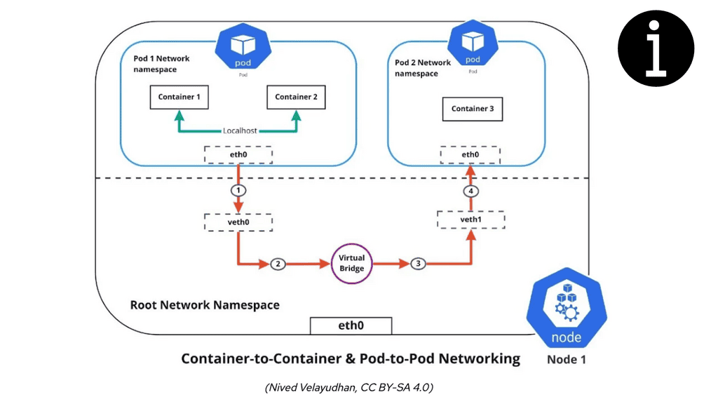
Kubernetes uses network namespaces primarily at the Pod level. Each Pod normally receives its own network namespace and Pod IP address. All containers within that Pod share the same network namespace, meaning they share the same network interfaces, IP address, routing table and port space.

This is an important distinction. Containers in the same Pod do not normally receive separate network identities. Instead, they communicate with each other through localhost and must coordinate the ports they use. Containers in different Pods normally have different network namespaces and different Pod IP addresses.

The CNI plugin is responsible for connecting the Pod’s network namespace to the wider cluster network. During Pod creation, the CNI implementation can create or configure interfaces, assign addresses and routes, and connect the Pod to the node or overlay network. Different CNI implementations provide different networking, routing, security and observability capabilities.

A simplified packet path can therefore be viewed as:

Pod container → Pod network namespace → virtual interface → CNI networking → Node/network fabric → destination Pod or external network

Within the Pod, containers communicate through the shared network namespace. When traffic leaves the Pod, the CNI implementation and node networking determine how that traffic reaches another Pod, Service, Node or external destination.

Network namespaces also contribute to isolation. A Pod does not normally see the network interfaces and sockets belonging to another Pod’s network namespace. However, namespace isolation should not be confused with complete security isolation. Kubernetes network security also depends on mechanisms such as NetworkPolicy, CNI enforcement, node firewalling and workload-level controls.

Services operate at a different abstraction level. A Service provides a stable virtual endpoint for reaching a group of Pods, while EndpointSlices identify the current backend endpoints. The Service mechanism and networking implementation then determine how traffic is delivered to those Pods.

The Kubernetes node itself has its own network namespace, separate from the namespaces used by Pods. This allows the node to maintain its own interfaces, addresses and routes while providing networking for workloads running on it.

Network namespaces are therefore one of the Linux primitives that make Kubernetes networking possible, but they are only one part of the complete architecture. Understanding the relationship between Pod namespaces, CNI, virtual interfaces, routing, Services and NetworkPolicy is far more useful than viewing namespaces in isolation.

For network engineers, the key concept is simple: a Kubernetes Pod is normally the network isolation boundary, not the individual container. Containers inside the same Pod share a network namespace and network identity, while separate Pods normally receive separate namespaces and Pod IP addresses. This model provides the foundation on which Kubernetes cluster networking is built.

KUBERNETES NETWORKING · INTERACTIVE MODEL

Follow a Packet Through a Network Namespace

See how a Pod's isolated network stack connects through its virtual interface and node networking to reach another workload or external network.
LINUX NETNS + CNI
Packet Processing Path
Worker Node · node-01
LINUX KERNEL
◈
Pod Network NS eth0 · Pod IP
isolated routing table
→
⇄
Virtual Interface veth pair / CNI attachment
→
◇
Node Datapath bridge / routing / overlay
→
◎
Destination Remote Pod
Pod Network Identities
frontend-7d8f
READY
Pod IP · 10.42.1.15 Namespace · app
api-5b76
READY
Pod IP · 10.42.2.21 Namespace · app
db-0
READY
Pod IP · 10.42.2.40 Namespace · data
Packet Trace Console
[READY] Select a traffic path and trace the packet.
Educational model: Kubernetes networking depends on the selected CNI and cluster configuration. A Pod normally has its own network namespace, while containers in the same Pod share that network namespace.
Network Namespace State
Network Isolation Pod scoped
Interface Boundary veth
Routing Stage Pod routing
Policy Result Permitted
ENGINEERING INSIGHT A network namespace provides an isolated network stack. CNI networking then connects that isolated Pod interface into the wider cluster datapath.

Highlights: Kubernetes Network Namespace

**Understanding Network Namespaces**

A network namespace is a fundamental Linux kernel feature that provides isolation of network resources. Each namespace has its own separate network stack, which includes its own interfaces, routing tables, and firewall rules. This means that processes running in one network namespace cannot communicate with processes in another unless explicitly configured to do so. In Kubernetes, each pod is assigned a unique network namespace, allowing it to manage its network interfaces independently of other pods.

**The Role of Network Namespaces in Kubernetes**

In Kubernetes, network namespaces play a pivotal role in achieving the platform’s goal of providing a “flat” network. This approach ensures that every pod in a cluster can communicate with any other pod without NAT (Network Address Translation). The network namespace allows Kubernetes to assign each pod a unique IP address, simplifying the communication process. This isolation also enhances security, as it limits the network attack surface by preventing unauthorized access across different namespaces.

Understanding Kubernetes Network Namespace

Kubernetes Network Namespace is a mechanism that allows multiple pods to have their own isolated network stack. It provides a separate network environment for each pod, enabling them to communicate securely and efficiently. By utilizing Network Namespace, you can easily define network policies, control traffic flow, and enhance the security of your applications.

Key Considerations:

1. Microservices Architecture: With Kubernetes Network Namespace, you can encapsulate different microservices within their own network namespaces. This isolation ensures that each microservice operates independently, preventing any interference or unauthorized access.

2. Testing and Development: Network Namespace is also useful for testing and development purposes. By creating separate namespaces for different stages of the development lifecycle, you can simulate real-world scenarios and identify potential issues before deploying to production.

3. Multi-Tenancy: Kubernetes Network Namespace allows you to achieve multi-tenancy by providing isolated network environments for different tenants or teams. This segregation ensures that each tenant or team has its own dedicated network resources and prevents any cross-communication or security breaches.

4. Network Segmentation: By utilizing Network Namespace, Kubernetes allows for the segmentation of network resources. This means that different pods can reside in their own isolated network environments, preventing interference and enhancing security.

5. Traffic Shaping and QoS: With Kubernetes Network Namespace, administrators can finely tune and shape network traffic for specific pods or groups of pods. This allows for better Quality of Service (QoS) management and optimized network performance.

Google Kubernetes EngineManaging Kubernetes Network Namespace

To implement Network Namespace in Kubernetes, one can leverage the powerful networking capabilities provided by container runtimes like Docker or CRI-O. By configuring the network plugin and defining network policies, pods can be assigned to specific network namespaces.

1. Creating a Network Namespace: To create a Network Namespace in Kubernetes, you can use the “kubectl” command-line tool or define it in YAML manifest files. By specifying the network policies, IP addresses, and other configuration parameters, you can create a customized namespace to suit your requirements.

2. Network Policy Enforcement: Kubernetes Network Namespace supports network policies that enable fine-grained control over traffic flow. By defining ingress and egress rules, you can restrict communication between pods within and across namespaces, enhancing the overall security of your cluster.

Kubernetes Pods & Services

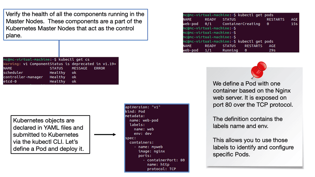
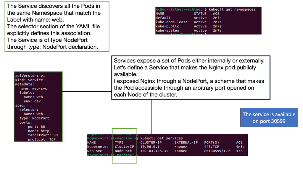
To comprehend the deployment process in Kubernetes, we must first grasp the concept of pods. A pod is the smallest unit of deployment in Kubernetes, representing a group of one or more containers that share resources and network. Pods are designed to work together and are scheduled onto nodes, forming the building blocks of your application.

Now that we have a solid understanding of pods let’s dive into the process of deploying one. To deploy a pod in Kubernetes, you need to define its specifications in a YAML file. This includes specifying the container image, resource requirements, environment variables, and any necessary volume mounts. Once the YAML file is ready, you can use the `kubectl` command-line tool to create the pod.

Introducing Services: While pods provide a scalable and manageable deployment unit, they are temporary, making them unsuitable for long-term accessibility. This is where services come into play. Services in Kubernetes provide a stable network endpoint to access a set of pods, allowing for seamless communication between components within a cluster.

Deploying a service in Kubernetes involves defining a service YAML file that specifies the service type, port mappings, and the selector to determine which pods the service should target. Once the service YAML file is configured, you can create the service using the `kubectl` command-line tool. This will ensure your application’s components are discoverable and accessible within the cluster.

Benefits of Kubernetes Network Namespace:

1. Enhanced Network Isolation: Kubernetes Network Namespace provides a robust framework for isolating network resources, ensuring that pods do not interfere with each other’s network traffic. This isolation helps prevent unauthorized access, reduces the attack surface, and enhances overall security within a Kubernetes cluster.

2. Efficient Resource Utilization: Kubernetes optimizes network resource utilization by utilizing network namespaces. Pods within a namespace can share the same IP address range while maintaining complete isolation, resulting in more efficient use of IP addresses and reduced network overhead.

3. Simplified Networking Configuration: Kubernetes Network Namespace simplifies the configuration of network policies and routing rules. Administrators can define network policies at the namespace level, allowing for granular control over inbound and outbound traffic between pods and external resources.

4. Scalability and Flexibility: With Kubernetes Network Namespace, organizations can scale their applications without worrying about network conflicts. By encapsulating each pod within its network namespace, Kubernetes ensures that the network resources can scale seamlessly, enabling the deployment of complex microservices architectures.

Kubernetes network namespace

Container Network Interface (CNI)

The Container Network Interface (CNI) is a crucial component that enables different networking plugins to integrate with Kubernetes. We will delve into the inner workings of CNI and discover how it facilitates communication between Pods and the integration of external networks. Understanding CNI will empower you to choose the right networking solution for your Kubernetes cluster.

The Role of Docker

In addition to my theoretical post on container networking – Docker & Kubernetes, the following hands-on series examines Linux Namespaces and Docker Networking. The advent of Docker makes it easy to isolate the Linux processes so they don’t interfere with one another. As a result, users can run various applications and dependencies on a single Linux machine, all sharing the same Linux kernel. This abstraction is made possible using Linux Namespaces, which form the docker container security basis.


KUBERNETES NETWORKING · EXPERIMENT LAB

Test Pod Connectivity Across Network Boundaries

Change the namespace relationship, CNI datapath and traffic policy. Then run a packet test and determine whether the workload can reach its destination.
EXPERIMENT · TEST · DIAGNOSE
Live Network Model
◈
Source Pod frontend-7d8f
10.42.1.15
▣
Network Namespace isolated stack
routes + interfaces
⇄
CNI Datapath routed Pod network
◎
Destination api-5b76
frontend-7d8f READY
Namespace: app IP: 10.42.1.15
api-5b76 READY
Namespace: app IP: 10.42.2.21
db-0 READY
Namespace: data IP: 10.42.2.40
Connectivity Console
[READY] Configure the experiment and run the connectivity test.
Educational model: exact CNI routing, encapsulation, NAT and policy enforcement vary by cluster configuration and networking plugin. The experiment focuses on the underlying networking concepts.
Experiment Results
Namespace Boundary Same
CNI Path Direct
Policy Decision Allowed
Reachability Not tested
ENGINEERING INSIGHT Run the experiment to see how namespace boundaries and network policy affect Pod connectivity.

Kubernetes Network Namespace

Moving from physical to virtual networks using software-defined networks (SDNs) and virtual interfaces involves a slight learning curve. The principles remain the same despite the differences in specifications and best practices. Understanding how Kubernetes networking works is helpful when dealing with containers and the cloud.

There are a few general rules to keep in mind when using the Kubernetes Network Model:

  • Every pod’s IP address is unique, so There should be no need to create links between pods or map container ports to host ports.
  • It is not necessary to use NAT: Pods on a node should be able to communicate with Pods on all nodes without using NAT.
  • Agents (system daemons, Kubelets) can contact Pods in a node.
  • Containers within a pod share an IP address and MAC address, allowing them to communicate using the loopback address.

In Kubernetes, networking ensures communication between different entity types. Separation is built into the infrastructure by design. A highly structured communication plan is necessary to keep namespaces, containers, and pods distinct.

Understanding Container Networking Models

There are various container networking models, each offering distinct advantages and use cases. Let’s explore two popular models:

1. Bridge Networking: The bridge networking model creates a virtual network bridge that connects containers running on the same host. Containers within the same bridge network can communicate directly with each other, whereas containers in different bridge networks require additional configuration for communication.

open vswitch

2. Overlay Networking: The overlay networking model allows containers running on different hosts to communicate seamlessly. It achieves this by encapsulating network packets within existing network protocols, effectively creating a virtual network overlay across multiple hosts.

Multicast VXLAN
Diagram: Multicast VXLAN

Kubernetes Networking

Kubernetes users generally do not create pods directly. Instead, they make a high-level workload, such as a deployment, which organizes pods according to some intended specifications. In the case of deployment, users specify a template for pods and how many pods (often called replicas) they want to exist.

Several additional ways to manage workloads exist, such as ReplicaSets and StatefulSets. Remember that pods are temporary, so they are suggested to be deleted and replaced with new versions.

Kubernetes Networking 101
Diagram: Kubernetes Networking 101

How Kubernetes Network Namespace Works:

Kubernetes Network Namespace leverages the underlying Linux kernel’s network namespace feature to create separate network environments for each pod. When a pod is created, Kubernetes assigns a unique network namespace, isolating the pod’s network stack from other pods in the cluster.

Each pod has network interfaces, IP addresses, routing tables, and firewall rules within a network namespace. This isolation allows each pod to operate as if it were running on its virtual network, even though it shares the same underlying physical network infrastructure.

Administrators can define network policies at the namespace level, controlling traffic flow between pods within the same namespace and across different namespaces. These policies enable fine-grained control over network traffic, enhancing security and allowing for the implementation of complex networking scenarios.

Docker Default Networking 101 & Linux Namespaces

Six namespaces are implemented in the Linux kernel, enabling the core of container-based virtualization. The following diagram displays per-process isolation: IPC, MNT, NET, PID, USER, and UTS. The number on the right in the square brackets is each namespace’s unique proc inode number.

A structure called nsproxy was added to implement namespaces in the Linux kernel. As the name suggests, it’s a namespace proxy. We have several userspace packages to support namespaces: util-linux, iproute2, ethtool, and wireless iw. This hands-on series will focus on the iproute2 userspace, which allows network namespace (NET) management with the IP NETNS and IP LINK commands.

Docker Networking

Docker networking, essentially a namespacing tool, can isolate processes into small containers. Containers differ from VMs that emulate a hardware layer on the operating system. Instead, they use operating system features like namespaces to provide similar isolation without emulating the hardware layer.

Docker networking

Each namespace has an individual and isolated view, allowing sharing of the same host but with separate routing tables and interfaces.

Users may create namespaces, assign ports, and connect for external connectivity. A virtual interface type known as a virtual Ethernet (veth) interface is set to namespaces. They act as pairs and resemble an isolated tube—what comes in one end must go back out the other.

The pairing enables namespace connectivity. Users may also connect namespaces using Open vSwitch. The following screenshot displays the creation of a namespace called NAMESPACE, a veth pair, and adding a veth interface to the newly created namespace. As discussed, the IP NET and IP LINK commands enable interaction with the network namespace. 

Docker Networking

The following screenshot displays IP-specific parameters for the previously created namespace. The routing table will only show specific namespace parameters, not information from other namespaces. For example, the following ip route list command does not display the 192.168.1.1/24 interface assigned to the NAMESPACE-A.

This is because the ip route list command looks into the global namespace, not the routing table assigned to the new namespace. Instead, the command will show different route table entries, including different default gateways for each namespace. 

Netnamespace

Kubernetes Network Namespace & Docker Networking

Installing Docker creates three networks that can be viewed by issuing the docker network ls command: bridge, host, and null. Running containers with a specific –net flag highlights the network in which you want to run the container. The “none” flag puts the container in no network, so it’s completely isolated. The “host” flag puts the container in the host’s network.

inspecting container networks
Diagram: Inspecting container networks

Leaving the defaults places the container into the bridge default network. The default docker bridge is what you will probably use most of the time. Any containers connected to the default bridge, like a flat VLAN, can communicate freely. The following displays the networks created and any containers attached. Currently, no containers are attached.

docker network

The image below displays the initiation of the default Ubuntu image pulled from the Docker public registry. There are plenty of images up there that are free to pull down. As you can see, Docker automatically creates a subnet and a gateway. The docker run command starts the container in the default network.

With this setup, it will stop running if you don’t use crtl+p + ctrl +q to exit the container. Running containers are viewed with the docker ps command, and users can connect to a container with the Docker attach command. \

docker network

IPTables

IPtables operate by examining network packets as they traverse through the network stack. Each packet is analyzed against a series of rules defined by the administrator. These rules can be based on parameters such as source/destination IP addresses, protocols, port numbers, etc. When a packet matches a rule, the specified action, such as accepting or dropping the packet, is carried out.

Communication between containers can be restricted with IPTables. The Linux kernel uses different IPtables according to the protocol in use:

  •  IPtables for IPv4 – net/ipv4/netfliter/ip_tables.c
  •  IP6table for IPv6 -net/ipv6/netfliter/ip6_tables.c
  •  arptables for ARP -net/ipv4/netfliter/arp_tables.c
  •  ebtables for Ethernet – net/bridge/netfilter/ebtables.c

Docker Security Options

They are essentially a Linux firewall before the Netfilter, providing a management layer for adding and deleting Netfilter rules and displaying statistics. The Netfilter performs various operations on packets traversing the network stack. Check the FORWARD chain; it has a default policy of ACCEPT or DROP.

All packets reach this hook point after a lookup in the routing system. The following screenshot shows the permit for all sources of the container. If you want to narrow this down, restrict only source IP 8.8.8.8 access to the containers with the following command – iptables -I DOCKER -i ext_if! -s 8.8.8.8 -j DROP

IPTABLES

In addition to the default networks created during Docker installation, users may create user-defined networks. User-defined networks come in two forms – Bridge and Overlay networks. Bridge networks support single-host connectivity, and containers connected to an overlay network may reside on multiple hosts.

The user-defined bridge network is similar to the docker0 bridge. An overlay network allows containers to span multiple hosts, enabling a multi-host connectivity model. However, it has some prerequisites, such as a valid data store. 

KUBERNETES NETWORKING · INCIDENT INVESTIGATION

Why Can't This Pod Reach the API?

The application is healthy, but requests from one Pod are timing out. Use the evidence to identify whether the fault is in the network namespace, CNI path, Service or network policy.
INCIDENT · DIAGNOSE
INCIDENT · APP CONNECTIVITY DEGRADED SEV-2

frontend-7d8f can resolve the API Service name, but TCP connections to the API are timing out. The API Pod is healthy and its readiness probe is passing. A network policy was changed shortly before the incident.

Evidence Collected
Frontend Pod RUNNING
API Pod READY
DNS / Service RESOLVES
CNI Interface UP
TCP / 443 TIMEOUT
Recent Change NETWORK POLICY
Suspected Network Path
frontend 10.42.1.15
namespace: app
→
Pod NS routing + eth0
→
CNI datapath
→
Policy traffic decision
→
api 10.42.2.21
TCP/443
What should you investigate first?
Diagnosis 0 / 4
Incident Console
[INCIDENT] frontend → API TCP/443 timeout
[INFO] frontend Pod RUNNING
[INFO] API Pod READY
[INFO] Service DNS resolution successful
[WARN] NetworkPolicy changed shortly before incident
Educational scenario: real Kubernetes network enforcement depends on the CNI and policy implementation. The evidence deliberately points toward policy rather than proving that every cluster implements the same datapath.
Investigation Signals
Pod Health GOOD
Service Discovery GOOD
CNI Interface UP
TCP Reachability FAILED
Policy Change RECENT
ENGINEERING INSIGHT Start with the strongest evidence. The Pods are healthy, DNS works and the CNI interface is up. A recent policy change combined with a TCP timeout makes traffic policy the highest-value investigation point.