network overlays

What is FabricPath

What is Fabric Path

In today's digital era, businesses rely heavily on networking infrastructure to ensure seamless communication and efficient data transfer. Cisco FabricPath is a cutting-edge technology that provides a scalable and resilient solution for modern network architectures. In this blog post, we will delve into the intricacies of Cisco FabricPath, exploring its features, benefits, and use cases.

Cisco FabricPath is a comprehensive network virtualization technology designed to address the limitations of traditional Ethernet networks. It offers a flexible and scalable approach for building large-scale networks that can handle the increasing demands of modern data centers. By combining the benefits of Layer 2 simplicity with Layer 3 scalability, Cisco FabricPath provides a robust and efficient solution for building high-performance networks.

Cisco Fabric Path is a networking technology that provides a scalable and flexible solution for data center networks. It leverages the benefits of both Layer 2 and Layer 3 protocols, combining the best of both worlds to create a robust and efficient network infrastructure.

- Simplified Network Design: One of the key advantages of Cisco Fabric Path is its ability to simplify network design and reduce complexity. By utilizing a loop-free topology and eliminating the need for complex Spanning Tree Protocol (STP) configurations, Fabric Path streamlines the network architecture and improves overall efficiency.

- Increased Scalability: Scalability is a crucial aspect of any modern network infrastructure, and Cisco Fabric Path excels in this area. With its support for large Layer 2 domains and the ability to accommodate thousands of VLANs, Fabric Path provides organizations with the flexibility to scale their networks as per their evolving needs.

- Enhanced Traffic Load Balancing: Cisco Fabric Path incorporates Equal-Cost Multipath (ECMP) routing, which enables efficient distribution of traffic across multiple paths. This results in improved performance, reduced congestion, and enhanced load balancing capabilities within the network.

- Converged Traffic and Virtualization: Fabric Path allows for the convergence of both Ethernet and Fibre Channel traffic onto a single infrastructure, simplifying management and reducing costs. Additionally, it seamlessly integrates with virtualization technologies, enabling organizations to leverage the benefits of virtual environments without compromising on performance or security.

Highlights: What is Fabric Path

Nexus OS Software Release

Introduced by Cisco in Nexus OS software Release 5.1(3), FabricPath Nexus allows architects to design highly scalable actual Layer 2 fabrics. Similar to the spanning tree, it provides an almost plug-and-play deployment model with the benefits of Layer 3 routing, allowing FabricPath networks to scale at an unprecedented level.

In addition to its simplicity, Fabric Path enables faster, simpler, and flatter data center networks. Cisco FabricPath uses routing principles to allow Layer 2 scaling. Therefore, it brings the stability of Layer 3 routing to Layer 2Fabric path traffic is no longer forwarded along a spanning tree design. As a result, we now have a more scalable design that is not limited by bisectional bandwidth.

The need for layer 2 

In the past, data centers were designed primarily to provide high availability. Layer 2 is crucial for modern data centers. Today’s networks must be agile and flexible, just like the organizations they serve. Since switching allows devices to be moved and infrastructure to be modified transparently, expanding the Layer 2 domain would satisfy this additional requirement. On the other hand, existing switching technologies rely on inefficient forwarding schemes based on spanning trees that cannot be extended to the entire network. The flexibility of Layer 2 compromises the scalability of Layer 3.

Spanning Tree Root Switch


Routing concepts at layer 2

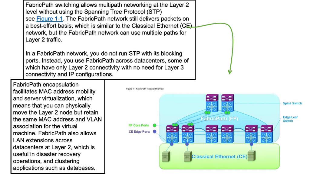
Cisco FabricPath: Expanding Routing Concepts to Layer 2 Cisco® FabricPath extends routing stability and scalability to Layer 2 of Cisco NX-OS. Workloads can be moved across the entire data center by eliminating the need to segment the switched domain. As a result, the bisectional bandwidth of the network is no longer limited by a spanning tree, allowing for massive scalability.

An entirely new Layer 2 data plane is created with Cisco FabricPath, where frames enter the fabric with routable source and destination addresses. The source address of a frame is its receiving switch’s address, and its destination address is its destination switch’s address. As soon as the frame reaches the remote switch, it is de-encapsulated and delivered in its original Ethernet format.

The role of Fabric Path

In large data centers, virtualization of physical servers began a few years ago. Due to server virtualization and economies of scale, “mega data centers” containing tens of thousands of servers emerged due to server virtualization. As a result, distributed applications had to be supported on a large scale and provisioned in different data center zones. A scalable and resilient Layer 2 fabric was required to enable any-to-any communication. FabricPath was developed by Cisco to meet these new demands. Providing scalability, resilience, and flexibility, FabricPath is a highly scalable Layer 2 fabric.

FabricPath

Fabric Path Requirements

Massive Scalable Data Centers (MSDCs) and virtualization technologies have led to the development of large Layer 2 domains in data centers with more than 1000 servers and a design for scalability. Due to the limitations of Spanning Tree Protocol (STP), Layer 2 switching has evolved into technologies such as TRILL and FabricPath. To understand FabricPath’s limitations, you need to consider the limitations of current Layer 2 networks based on STP:
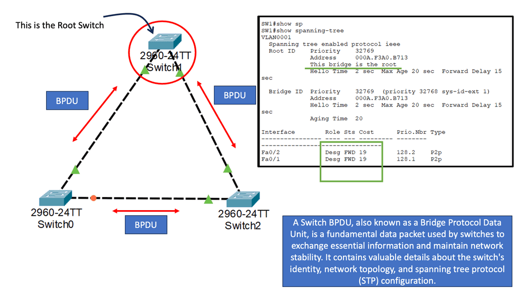
By blocking redundant paths, STP creates loop-free topologies in Layer 2 networks. STP uses the root selection process to accomplish this. To build shortest paths to the root switch, all the other switches block the other ports while building shortest paths to the root switch. The result is a Layer 2 network topology that is loop-free. This blocks layer 2 networks because all redundant paths are blocked. PVST, which enables per-VLAN load balancing, also has limitations in multipathing support, although some enhancements were made using the per-VLAN Spanning Tree Protocol (PVSTP).
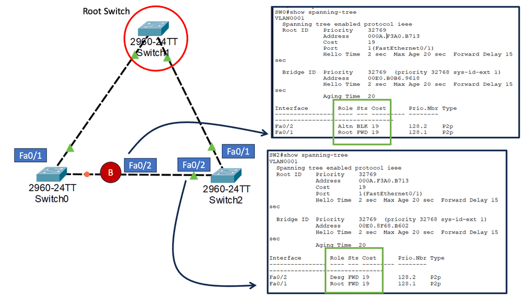
The root bridge is selected based on the shortest path, which results in inefficient path selection between switches. So, selecting a path between switches doesn’t necessarily mean choosing the shortest path. Take two access switches as an example connected to distribution and each other. If the distribution switch serves as the root bridge for STP, the link between the two access switches is blocked. All traffic flows through the distribution switch.

Unavailability of Time-To-Live (TTL): The Layer 2 packet header doesn’t have a TTL field. This can lead to network meltdowns in switched networks. This is because a forwarding loop can cause a broadcast packet to duplicate, consuming excessive network resources exponentially.

STP Path distribution

MAC address scalability: Nonhierarchical flat addressing of Ethernet MAC addresses leads to limited scalability since MAC address summarization is impossible. Additionally, all the MAC addresses are essentially assigned to every switch in the Layer 2 network, increasing the size of Layer 2 tables.

As a result, Layer 3 routing protocols provide multipathing and efficient shortest paths between all nodes in the network, which resolve the shortcomings of Layer 2 networks. Layer 3 solves these issues, but the network design becomes static. Static network design limits Layer 2 domain size, so virtualization cannot be used. Thanks to FabricPath’s combination of the two technologies, a Layer 2 network can be flexible and scaled with Layer 3 networks.

stp port states

Fabric Path Benefits

With FabricPath, data center architects and administrators can design and implement scalable Layer 2 fabrics. Benefits of FabricPath include:

Maintains the plug-and-play features of classical Ethernet: Due to the minimal configuration requirements and the fact that the administrator must include the FabricPath core network interfaces, configuration effort is significantly reduced. Unicast forwarding, multicast forwarding, and VLAN pruning are also controlled by a single protocol (IS-IS). FabricPath operations, administration, and management (OAM) now support ping and trace routes, allowing network administrators to troubleshoot Layer 2 FabricPath networks similarly to Layer 3 networks.

Multipathing allows data center network architects to build large, scalable networks using N-way (more than one path) multipathing. A network administrator can also incrementally add new devices as needed to the existing topology. Using flat topologies, MSDC networks can be connected by only one hop between nodes. A single node failure in N-way multipathing results in a reduction in fabric bandwidth of 1/Nth.

With the enhanced Layer 2 network capabilities combined with Layer 3 capabilities, multiple paths can be created between endpoints instead of just one, replacing STP. It allows network administrators to increase bandwidth as bandwidth requirements increase incrementally.

The FabricPath protocol enables traffic to be forwarded over the shortest path to the destination, reducing network latency. This is more efficient than Layer 2 forwarding based on STP.

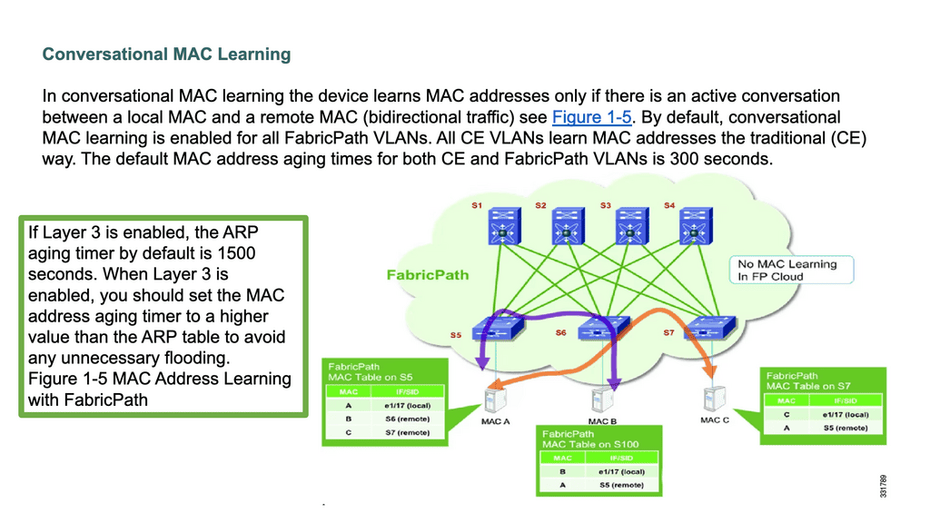
With FabricPath, MAC addresses are learned selectively based on active flows with conversational MAC learning. As a result, the need for large MAC tables is reduced.

Related: Before you proceed, you may find the following posts helpful:

  1. What is VXLAN
  2. Data Center Fabric
  3. Nexus 1000
  4. SDN Data Center
  5. Data Center Network Design
  6. Cisco ACI

Cisco FabricPath

Key What is FabricPath Discussion Points:


  • Introduction to What is FabricPath and what is involved.

  • Highlighting the details of FabricPath Nexus and the components involved.

  • Technical details on the issues with STP.

  • Scenario: Fabric Path use cases.

  • A final note on the Fabric Patch control plane and IS-IS.

Back to Basics: Cisco FabricPath.

We must support distributed applications at a considerable scale and have the flexibility to provision them in different zones of data center topologies. This necessitated creating a scalable and resilient Layer 2 fabric enabling any-to-any communication without workload placement restrictions—Cisco developed FabricPath to meet these new demands.

FabricPath is a powerful network technology from Cisco Systems that provides a unified, programmable fabric to connect, manage, and optimize data center networks. It is based on a distributed Layer 2 network protocol that enables the creation of multi-tenant, multi-domain, and multi-site networks with a single, unified control plane. FabricPath operates on a flat, non-hierarchical topology designed to simplify network virtualization and automation.

FabricPath delivers a highly scalable Layer 2 fabric. It uses a single control protocol (IS-IS) for unicast forwarding, multicast forwarding, and VLAN pruning. FabricPath also enables traffic to be forwarded across the shortest path to the destination, thus reducing latency in the Layer 2 network. This is more efficient than Layer 2 forwarding based on the STP.

FabricPath includes several features that make it ideal for large enterprise networks and data centers. It uses a distributed control plane to provide a unified view of the network and reduce network complexity. In addition, FabricPath supports virtualization, allowing the creation of multiple virtual networks within the same physical infrastructure. It also allows the creation of multiple forwarding instances and provides fast convergence times.

FabricPath
Diagram: FabricPath. Source is Cisco

The Challenges Of Inefficient Forwarding Schemes

The challenge is that existing switching technologies have inefficient IP forwarding schemes based on spanning trees and cannot be extended to the network. Therefore, current designs compromise the flexibility of Layer 2 and the scaling offered by Layer 3. On the other hand, Fabric Path introduces a new method of forwarding. 

The data design can stay the same as a leaf and spine. Still, we have a new Layer 2 data plane with fabric paths that encapsulate the frames entering the fabric with a header consisting of routable source and destination addresses.

These addresses are the address of the switch on which the frame was received and the address of the destination switch to which the frame is heading. From there, the frame is routed until it reaches the remote switch, where it is de-encapsulated and delivered in its original Ethernet format. FabricPath Nexus also uses a Shortest Path First (SPF) routing protocol to determine reachability and path selection in the FabricPath domain.

With Fabric Path, we have a simple and flexible behavior of Layer 2 while using the routing mechanisms that make IP reliable and scalable. So you may ask, what about the Layer 2 and 3 boundaries? The Layer 2 and 3 boundary still exists in a data center based on Cisco FabricPath. However, there is little difference in how traffic is forwarded in those two distinct areas of the network. The following sections discuss the drivers for FabricPath and what you may opt for in its design.

Why Cisco Fabricpath?

1) No Multipathing support at Layer 2: Spanning Tree Protocol ( STP ) lacks any good Layer 2 multipathing features for large data centers. The protocol has been enhanced with PVST per VLAN load balancing, but this feature can only load balance on VLANs.

2) MAC address scalability: Layer 2 end hosts are discovered by their MAC address, and this type of host addressing cannot be hierarchical and summarized. For example, one MAC address cannot represent a stub of networks. Traditional Layer 3 networks overcome this by introducing ABRs in OSPF or summarization/filtering in EIGRP. Also, in the Layer 2 network, all the MAC addresses are populated in ALL switches, leading to large requirements in the Layer 2 table sizes.

3) Instability of Layer 2 networks: Layer 3 networks have an eight-bit Time to Live ( TTL ) field that prevents datagrams from persisting (e.g., going in circles ) on the internet. However, compared to Layer 3 headers, the Layer 2 packet header does not have a TTL field. The lack of a TTL field will cause Layer 2 packets to loop infinitely, causing a network meltdown.

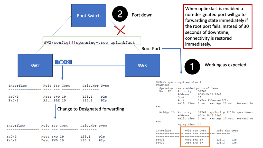
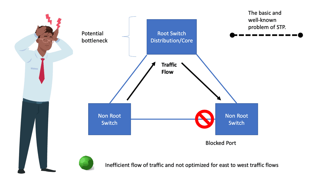
4) Incompetent path selection: The shortest path for a Layer 2 network depends on the placement of the Root switch. Depending on costs and port priorities, you can influence the root port selection ( forwarding port ), but the root switch’s placement is how the forwarding path is built. For example, in the diagram below, the most optimum traffic for the server-to-server flows would be via the inter-switch link, but as you can see, spanning tree blocks, this port, and traffic takes the sub-optimal path through the distribution switch.

Issues with Spanning Tree: Vendors’ responses.

A Spanning Tree allows only one path to be active between any two nodes and blocks the rest, making it unsuitable for low-latency data centers and cloud environments. Every vendor addressing the data center market proposes augmenting or replacing a Spanning Tree with a link-state protocol.

For example, Brocade uses TRILL in the data plane, while the control plane is based on Fabric Shortest Path First, an ANSI standard used by all Fibre Channel SAN fabrics as the link-state routing protocol.

On the other hand, Juniper implemented a tagging mechanism in the Broadcom silicon in its QFabric switches rather than a link-state protocol. Cisco FabricPath is considered a “superset” of TRILL, bringing scale to the data center and improving application performance.

Fabric Path typical use cases

Fabric Path can support any new protocol that can be done elegantly in IS-IS by adding new extensions without modifying the base infrastructure. Each IS-IS Intermediate router advertises one or more IS-IS Link State Protocol Data Units (LSPs) with routing information.

The LSP comprises a fixed header and several tuples, each consisting of a Type, a Length, and a Value. Such tuples are commonly known as TLVs and are a good way of encoding information in a flexible and extensible format. These make IS-IS a very extensible routing protocol, and FabricPath takes advantage of this extensibility.

This allows FarbicPath to support the following prominent use cases.

  1. Large flat data centers that need Layer 2 multipathing and equidistant endpoints.
  2. DC requires a reduction of Layer 2 table sizes ( done via MAC conversational learning ).
Fabric Path
Diagram: Fabric Path Conversational learning. Source is Cisco

Cisco FabricPath control plane

FabricPath is a Layer 2 overlay network with an IS-IS control plane. Using FabricPath IS-IS, the switches build their forwarding tables, similar to building the forwarding table in Layer 3 networks. The extensions used in IS-IS to support Fabricpath allow this Layer 2 overlay to take advantage of all the scalable and load balancing ( ECMP, up to 16 routes ) benefits of a Layer 3 network while retaining the benefits of a plug-and-play Layer 2 network.

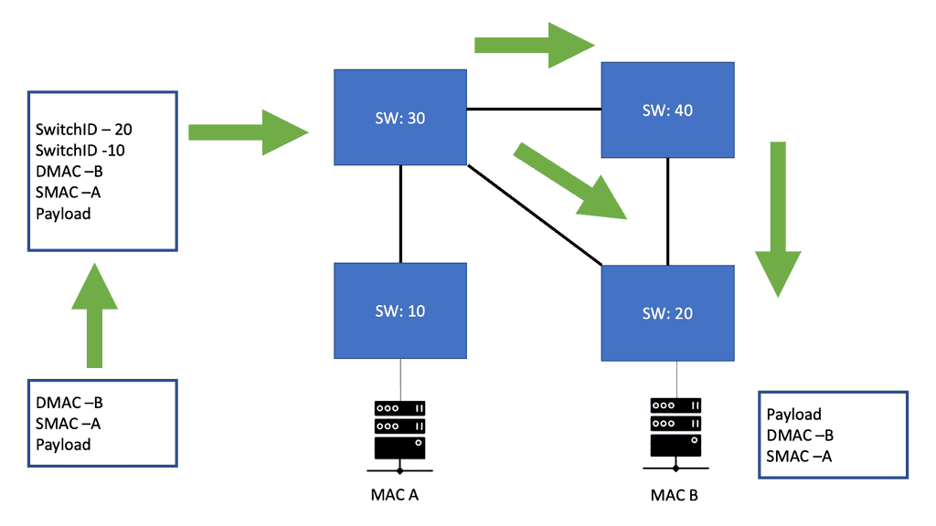
The FabricPath Header

The FabricPath header has a hop count in one of the fields, which mitigates temporary loops in FabricPath networks. This header uses locally assigned hierarchical MAC addresses for forwarding frames within the network. The original Layer 2 frames are encapsulated with a FabricPath header, and a new CRC is appended to the existing packet. One of the main elements of the FabricPath header is the SwitchID, and the core switches forward Fabricpath traffic by examining this field. The switch ID is the field used in the FabricPath domain to forward packets to the correct destination switch.

Why use IS-IS as the FabricPath Nexus control plane?

We touched on this just a moment ago. Its control protocol is built on top of the Intermediate System–to Intermediate System (IS-IS) routing protocol, which provides fast convergence and has been proven to scale up to the largest service provider environments.

  1. IS-IS is flexible and can be extended to support other functions with new type-length values (TLVs).
  2. TLV is also known as tag-length value and encodes optional information.IS-IS runs directly over the link layer, thereby preventing the need for any underlying Layer 3 protocol like IP to work.
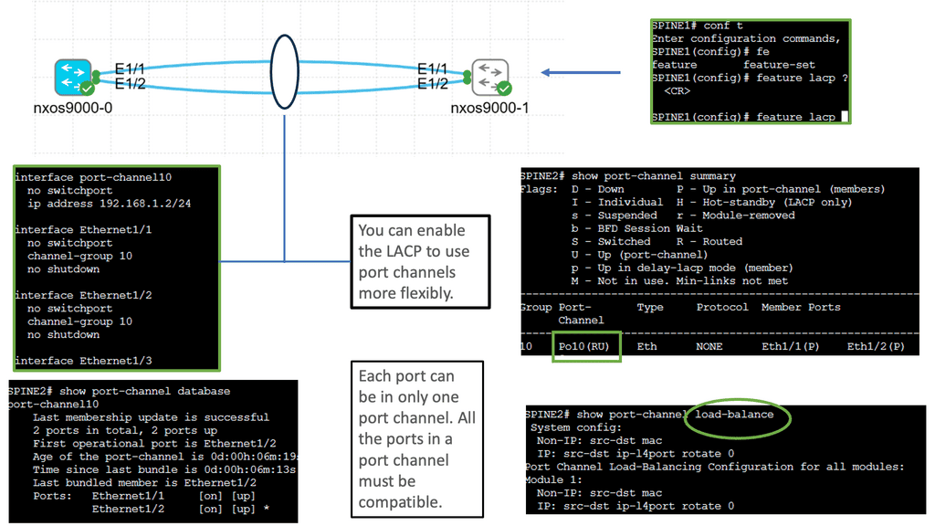
Virtual PortChannel

Fabricpath Nexus uses Virtual PortChannel. Now, we have multiple active link capabilities, resulting in active-active forwarding paths. The vPC allows a more granular design over the standard port channeling that only allows you to terminate on one switch. In addition, Cisco vPC enables a more flexible triangular design. Both aggregation technologies can use LACP for the control plane to negotiate the links.

Virtual Device Context

Fabricpath Nexus also uses Virtual Device Contexts (VDC), which allows each FabricPath control-plane protocol and functional block to run in its own protected memory space as individual processes for stability and fault isolation. A VDC design enables modular building blocks to improve security and performance.

FabricPath Nexus and conversational MAC learning

FabricPath Nexus performs conversational MAC learning, enabling a switch to learn only those MACs involved in active bidirectional communication. Similar to a three-way handshake, this new technique leads to the population of only the interested host’s MAC addresses rather than all MAC addresses in the domain. This dramatically reduces the need for large table sizes as each switch only learns the MAC addresses that the hosts under its interface are actively communicating with. As a result, edge nodes only know the MAC addresses of local nodes or nodes that want to speak with local nodes directly.

FabricPath Nexus benefits and drawbacks

Benefits  

Drawbacks

Plug-and-play features like Classical Ethernet

 Cisco proprietary

The single control plane for ALL types of traffic and good troubleshooting features to debug problems at Layer 2 

Fabric interfaces carry only FabricPath encapsulated traffic

High performance and high availability using multipathing**

Useful as a DCI solution only over short distances

Easy to add new devices to an existing FabricPath domain

NA

Small Layer 2 table sizes result in better performance

NA

** This enables the MSDC networks to have flat topologies, separating the nodes by a single hop.

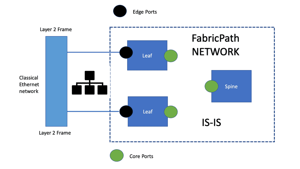
Although IS-IS forms the basis of Cisco FabricPath, you don’t need to be an IS-IS expert. You can enable FabricPath interfaces and begin forwarding FabricPath encapsulated frames in the same way they can activate Spanning Tree and interconnect switches.

The only necessary configuration is distinguishing the core ports, which link the switches, from the edge ports, where end devices are attached. No other parameters need to be tuned to achieve an optimal configuration, and the switch addresses are assigned automatically for you.

Summary: What is Fabric Path

Key Features of Cisco FabricPath:

1. MAC-in-MAC Encapsulation: Cisco FabricPath utilizes MAC-in-MAC encapsulation to overcome the traditional Spanning Tree Protocol (STP) limitations. By encapsulating Layer 2 frames within another Layer 2 frame, FabricPath enables efficient forwarding and eliminates the need for STP.

2. Loop-Free Topology: Unlike STP-based networks, Cisco FabricPath employs a loop-free topology, ensuring optimal forwarding paths and maximizing network utilization. This feature enhances network resilience and eliminates the risk of network outages caused by loops.

3. Scalability: Cisco FabricPath supports up to 16 million virtual ports, enabling organizations to scale their networks without compromising performance. This scalability makes it ideal for large data centers and enterprises with growing network demands.

4. Traffic Optimization: Cisco FabricPath optimizes traffic flows using Equal-Cost Multipath (ECMP) routing. ECMP distributes traffic across multiple paths, allowing for efficient load balancing and improved network performance.

Benefits of Cisco FabricPath:

1. Simplified Network Design: Cisco FabricPath simplifies network design by eliminating the need for complex STP configurations. With its loop-free architecture, FabricPath reduces network complexity and improves overall network stability.

2. Enhanced Network Resilience: Cisco FabricPath ensures high network availability and resilience by utilizing multiple paths and load balancing techniques. In the event of a link failure, traffic is automatically rerouted, minimizing downtime and enhancing network reliability.

3. Increased Performance: With its scalable design and traffic optimization capabilities, Cisco FabricPath delivers superior network performance. FabricPath minimizes bottlenecks and improves overall network throughput by distributing traffic across multiple paths.

Use Cases of Cisco FabricPath:

1. Data Center Networks: Cisco FabricPath is widely used in data center environments, providing a scalable and resilient networking solution. Its ability to handle high traffic volumes and optimize data flows makes it an ideal choice for modern data centers.

2. Virtualized Environments: Cisco FabricPath is particularly beneficial in virtualized environments, simplifying network provisioning and enhancing virtual machine mobility. Its scalability and flexibility enable seamless communication between virtualized resources.

Conclusion: Cisco FabricPath is a powerful networking solution that offers numerous benefits for organizations seeking scalable and resilient network architectures. With its loop-free topology, MAC-in-MAC encapsulation, and traffic optimization capabilities, Cisco FabricPath simplifies network design, enhances network resilience, and boosts overall performance. By implementing Cisco FabricPath, businesses can build robust and efficient networks that meet the demands of today’s digital landscape.

Data Center Network Design

Data Center Network Design

Data centers are crucial in today’s digital landscape, serving as the backbone of numerous businesses and organizations. A well-designed data center network ensures optimal performance, scalability, and reliability. This blog post will explore the critical aspects of data center network design and its significance in modern IT infrastructure.

Data center network design involves the architectural planning and implementation of networking infrastructure within a data center environment. It encompasses various components such as switches, routers, cables, and protocols. A well-designed network ensures seamless communication, high availability, and efficient data flow.

The traditional three-tier network architecture is being replaced by more streamlined and flexible designs. Two popular approaches gaining traction are the spine-leaf architecture and the fabric-based architecture. The spine-leaf design offers low latency, high bandwidth, and improved scalability, making it ideal for large-scale data centers. On the other hand, fabric-based architectures provide a unified and simplified network fabric, enabling efficient management and enhanced performance.

Network virtualization, powered by technologies like SDN, is transforming data center network design. By decoupling the network control plane from the underlying hardware, SDN enables centralized network management, automation, and programmability. This results in improved agility, better resource allocation, and faster deployment of applications and services.

With the rising number of cyber threats, ensuring robust security and resilience has become paramount. Data center network design should incorporate advanced security measures such as firewalls, intrusion detection systems, and encryption protocols. Additionally, implementing redundant links, load balancing, and disaster recovery mechanisms enhances network resilience and minimizes downtime.

Highlights: Data Center Network Design

Typical Composition of Data Center Architecture

A data center architecture consists of three main components: the data center network, the data center security, and the data center computing architecture. In addition to these three types of architecture, there are also data center physical architectures and data center information architectures. The following are three typical compositions. Network architecture for data centers: Data center networks (DCNs) are arrangements of network devices interconnecting data center resources. They are a crucial research area for Internet companies and large cloud computing firms. The design of a data center depends on its network architecture.

It is common for routers and switches to be arranged in hierarchies of two or three levels. There are three-tier DCNs: fat tree DCNs, DCells, and others. There has always been a focus on scalability, robustness, and reliability regarding data center network architectures. Architecting data center security: Data center security refers to physical practices and virtual technologies for protecting data centers from threats, attacks, and unauthorized access. It can be divided into two components: physical security and software security. Setting up a firewall between a data center’s external and internal networks can protect it from attack.

Developing a data center network

A network serves applications’ connectivity requirements, and applications serve their organizations’ business needs. To design or operate a network in a modern data center, you must first understand the needs and topology of the data center. Here we begin our journey. My goal is for you to understand the network design of a modern data center network based on the applications’ needs and the size of the data center.

Compared to a decade ago, data centers now have much larger capacity, vastly different applications, and deployment speeds in seconds rather than days. As a result, network design and deployment change.

Border Gateway Protocol (BGP) is data centers’ most commonly used routing protocol. BGP has been used to connect Internet systems around the world for decades. It can also be used outside of a data center. The BGP protocol is a standard-based open-source software package. Its more common to find BGP peering between data centers over the WAN. However, these days we are seeing BGP often used purely inside the data center. 

forwarding routing protoocols

Data Center Requirments

Google and Amazon, two of the world’s leading web-scale pioneers, developed a modern data center. The third wave of application architectures represents these organizations’ search and cloud applications. Towards the end of the 20th century, client-server architectures and monolithic single-machine applications dominated the landscape. This third wave of applications has three primary characteristics:

Unlike client-server architectures, modern data center applications involve a lot of communication between servers. In client-server architectures, clients communicate with monolithic servers, which either handle the request entirely themselves or communicate with fewer than a handful of other servers, such as database servers. Search (or Hadoop, its more popular variant) employs many mappers and reducers instead of search. In the cloud, virtual machines can reside on different nodes but must communicate seamlessly. In some cases, VMs are deployed on servers with the least load, scaled out, or balanced loads.

A microservices architecture also increases server-to-server communication. This architecture is based on separating a single function into smaller building blocks and interacting with them. Each block can be used in several applications and enhanced, modified, and fixed independently in such an architecture. Since diagrams usually show servers next to each other, East-West traffic is often called server communication. Traffic flows north-south between local networks and external networks.

Scale and resilience

The sheer size of modern data centers is characterized by rows and rows of dark, humming, blinking machines. As opposed to the few hundred or so servers of the past, a modern data center contains between a few hundred and a hundred thousand servers. To address the connectivity requirements at such scales, as well as the need for increased server-to-server connectivity, network design must be rethought. Unlike older architectures, modern data center applications assume failures as a given. Failures should be limited to the smallest possible footprint. Failures must have a limited “blast radius.” By minimizing the impact of network or server failures on the end-user experience, we aim to provide a stable and reliable experience.

Data Center Goal: Interconnect networks

The goal of data center design and interconnection network is to transport end-user traffic from A to B without any packet drops, yet the metrics we use to achieve this goal can be very different. The data center is evolving and progressing through various topology and technology changes, resulting in multiple network designs.  The new data center control planes we see today, such as Fabric Path, LISP, THRILL, and VXLAN, are driven by a change in the end user’s requirements; the application has changed. These new technologies may address new challenges, yet the fundamental question of where to create the Layer 2/Layer three boundaries and the need for Layer 2 in the access layer remains the same. The question stays the same, yet the technologies available to address this challenge have evolved.

what is spine and leaf architecture


Modern Data Centers

There is a vast difference between modern data centers and what they used to be just a few years ago. Physical servers have evolved into virtual networks that support applications and workloads across pools of physical infrastructure and into a multi-cloud environment. There are multiple data centers, the edge, and public and private clouds where data exists and is connected. Both on-premises and cloud-based data centers must be able to communicate. Data centers are even part of the public cloud. Cloud-hosted applications use the cloud provider’s data center resources.

Unified Fabric

Through Cisco’s fabric-based data center infrastructure, tiered silos and inefficiencies of multiple network domains are eliminated, and a unified, flat fabric is provided instead, which allows local area networks (LANs), storage area networks (SANs), and network-attached storage (NASs) to be consolidated into one high-performance, fault-tolerant network. Creating large pools of virtualized network resources that can be easily moved and rapidly reconfigured with Cisco Unified Fabric provides massive scalability and resiliency to the data center.

This approach automatically deploys virtual machines and applications, thereby reducing complexity. Thanks to deep integration between server and network architecture, secure IT services can be delivered from any device within the data center, between data centers, or beyond. In addition to Cisco Nexus switches, Cisco Unified Fabric uses Cisco NX-OS as its operating system.

leaf and spine design

The use of Open Networking

We also have the Open Networking Foundation ( ONF ), which provides open networking. Open networking describes a network that uses open standards and commodity hardware. So, consider open networking in terms of hardware and software. Unlike a vendor approach like Cisco, this gives you much more choice with what hardware and software you use to make up and design your network.

Related: Before you proceed, you may find the following useful:

  1. ACI Networks
  2. IPv6 Attacks
  3. SDN Data Center
  4. Active Active Data Center Design
  5. Virtual Switch

Data Center Control Plane

Key Data Center Network Design Discussion Points:


  • Introduction to data center network design and what is involved.

  • Highlighting the details of VLANs and virtualization.

  • Technical details on the issues of Layer 2 in data centers. 

  • Scenario: Cisco FabricPath and DFA.

  • Details on overlay networking and Cisco OTV.

The Rise of Overlay Networking

What has the industry introduced to overcome these limitations and address the new challenges? – Network virtualization and overlay networking. In its simplest form, an overlay is a dynamic tunnel between two endpoints that enables Layer 2 frames to be transported between them. In addition, these overlay-based technologies provide a level of indirection that allows switching table sizes to not increase in the order of the number of supported end hosts.

Today’s overlays are Cisco FabricPath, THRILL, LISP, VXLAN, NVGRE, OTV, PBB, and Shorted Path Bridging. They are essentially virtual networks that sit on top of a physical network, and often, the physical network is unaware of the virtual layer above it.

1st Lab Guide: VXLAN

The following lab guide displays a VXLAN network. We are running VXLAN in multicast mode. Multicast VXLAN is a variant of VXLAN that utilizes multicast-based IP multicast for transmitting overlay network traffic. VXLAN is an encapsulation protocol that extends Layer 2 Ethernet networks over Layer 3 IP networks.

Linking multicast enables efficient and scalable communication within the overlay network. Notice the multicast group of 239.0.0.10 and the route of 239.0.0.10 forwarding out the tunnel interface. We have multicast enabled on all Layer 3 interfaces, including the core that consists of Spine A and Spine B.

Multicast VXLAN
Diagram: Multicast VXLAN

Traditional Data Center Network Design

How do routers create a broadcast domain boundary? Firstly, using the traditional core, distribution, and access model, the access layer is layer 2, and servers served to each other in the access layer are in the same IP subnet and VLAN. The same access VLAN will span the access layer switches for east-to-west traffic, and any outbound traffic is via a First Hop Redundancy Protocol ( FHRP ) like Hot Standby Router Protocol ( HSRP ).

Servers in different VLANs are isolated from each other and cannot communicate directly; inter-VLAN communications require a Layer 3 device. Virtualization’s humble beginnings started with VLANs, which were used to segment traffic at Layer 2. It was expected to find single VLANs spanning an entire data center fabric.

Redundant Data Centers 

VLAN and Virtualization

The virtualization side of VLANs comes from two servers physically connected to different switches. Assuming the VLAN spans both switches, the same VLAN can communicate with each server. Each VLAN can be defined as a broadcast domain in a single Ethernet switch or shared among connected switches.

Whenever a switch interface belonging to a VLAN receives a broadcast frame ( destination MAC is ffff.ffff.ffff), the device must forward this frame to all other ports defined in the same VLAN.

This approach is straightforward in design and is almost like a plug-and-play network. The first question is, why not connect everything in the data center into one large Layer 2 broadcast domain? Layer 2 is a plug-and-play network, so why not? STP also blocks links to prevent loops.

stp port states

 The issues of Layer 2

The reason is that there are many scaling issues in large layer 2 networks. Layer 2 networks don’t have controlled / efficient network discovery protocols. Address Resolution Protocol ( ARP ) is used to locate end hosts and uses Broadcasts and Unicast replies. A single host might not generate much traffic, but imagine what would happen if 10,000 hosts were connected to the same broadcast domain. VLANs span an entire data center fabric, which can bring a lot of instability due to loops and broadcast storms.

Address Resolution Protocol

 No hierarchy in MAC addresses

MAC addressing also lacks hierarchy. Unlike Layer 3 networks, which allow summarization and hierarchy addressing, MAC addresses are flat. Adding several thousand hosts to a single broadcast domain will create large forwarding information tables.

Because end hosts are potentially not static, they are likely to be attached and removed from the network at regular intervals, creating a high rate of change in the control plane. Of course, you can have a large Layer 2 data center with multiple tenants if they don’t need to communicate with each other.

The shared services requirements, such as WAAS or load balancing, can be solved by spinning up the service VM in the tenant’s Layer 2 broadcast domain. This design will hit scaling and management issues. There is a consensus to move from a Layer 2 design to a more robust and scalable Layer 3 design.

But why is Layer 2 still needed in data center topologies? One solution is Layer 2 VPN with EVPN. But first, let us look at Cisco DFA.

The Requirement for Layer 2 in Data Center Network Design

  • Servers that perform the same function might need to communicate with each other due to a clustering protocol or simply as part of the application’s inner functions. If the communication is clustering protocol heartbeats or some server-to-server application packets that are not routable, then you need this communication layer to be on the same VLAN, i.e., Layer 2 domain, as these types of packets are not routable and don’t understand the IP layer.

  • Stateful devices such as firewalls and load balancers need Layer 2 adjacency as they constantly exchange connection and session state information.

  • Dual-homed servers: Single server with two server NICs and one NIC to each switch will require a layer 2 adjacency if the adapter has a standby interface that uses the same MAC and IP addresses after a failure. In this situation, the active and standby interfaces must be on the same VLAN and use the same default gateway.

  • Suppose your virtualization solutions cannot handle Layer 3 VM mobility. In that case, you may need to stretch VLANs between PODS / Virtual Resource Pools or even data centers so you can move VMs around the data center at Layer 2 ( without changing their IP address ).

Data Center Design and Cisco DFA

Cisco took a giant step and recently introduced a data center fabric with Dynamic Fabric Automaton ( DFA ), similar to Juniper QFabric. This fabric offers Layer 2 switching and Layer 3 routing at the access layer / ToR. Firstly, it has a Fabric Path ( IS-IS for Layer 2 connectivity ) in the core, which gives optimal Layer 2 forwarding between all the edges.

Then they configure the same Layer 3 address on all the edges, which gives you optimal Layer 3 forwarding across the whole Fabric.

On edge, you can have Layer 3 Leaf switches, for example, the Nexus 6000 series, or integrate with Layer 2-only devices like the Nexus 5500 series or the Nexus 1000v. You can also connect external routers or USC or FEX to the Fabric. In addition to running IS-IS as the data center control plane, DFA uses MP-iBGP, with some Spine nodes being the Route Reflector to exchange IP forwarding information.

Cisco FabricPath

DFA also employs a Cisco FabricPath technique called “Conversational Learning.” The first packet triggers a full RIB lookup, and the subsequent packets are switched in the hardware-implemented switching cache.

This technology provides Layer 2 mobility throughout the data center while providing optimal traffic flow using Layer 3 routing. Cisco commented, “DFA provides a scale-out architecture without congestion points in the network while providing optimized forwarding for all applications.”

Terminating Layer 3 at the access / ToR has clear advantages and disadvantages. Other benefits include reducing the size of the broadcast domain, which comes at the cost of reducing the mobility domain across which VMs can be moved.

Terminating Layer 3 at the accesses can also result in sub-optimal routing because there will be hair pinning or traffic tromboning of across-subnet traffic, taking multiple and unnecessary hops across the data center fabric.

FabricPath

The role of the Cisco Fabricpath

Cisco FabricPath is a Layer 2 technology that provides Layer 3 benefits, such as multipathing the classical Layer 2 networks using IS-IS at Layer 2. This eliminates the need for spanning tree protocol, avoiding the pitfalls of having large Layer 2 networks. As a result, Fabric Path enables a massive Layer 2 network that supports multipath ( ECMP ). THRILL is an IEEE standard that, like Fabric Path, is a Layer 2 technology that provides the same Layer 3 benefits as Cisco FabricPath to the Layer 2 networks using IS-IS.

LISP is popular in Active data centers for DCI route optimization/mobility. It separates the host’s location from the identifier ( EID ), allowing VMs to move across subnet boundaries while keeping the endpoint identification. LISP is often referred to as an Internet locator. 

That can enable some designs of triangular routing. Popular encapsulation formats include VXLAN ( proposed by Cisco and VMware ) and STT (created by Nicira but will be deprecated over time as VXLAN comes to dominate ).

The role of OTV

OTV is a data center interconnect ( DCI ) technology enabling Layer 2 extension across data center sites. While Fabric Path can be a DCI technology with dark fiber over short distances, OTV has been explicitly designed for DCI. In contrast, the Fabric Path data center control plane is primarily used for intra-DC communications.

Failure boundary and site independence are preserved in OTV networks because OTV uses a data center control plane protocol to sync MAC addresses between sites and prevent unknown unicast floods. In addition, recent IOS versions can allow unknown unicast floods for certain VLANs, which are unavailable if you use Fabric Path as the DCI technology.

The Role of Software-defined Networking (SDN)

Another potential trade-off between data center control plane scaling, Layer 2 VM mobility, and optimal ingress/egress traffic flow would be software-defined networking ( SDN ). At a basic level, SDN can create direct paths through the network fabric to isolate private networks effectively.

An SDN network allows you to choose the correct forwarding information per-flow basis. This per-flow optimization eliminates VLAN separation in the data center fabric. Instead of using VLANs to enforce traffic separation, the SDN controller has a set of policies allowing traffic to be forwarded from a particular source to a destination.

The ACI Cisco borrows concepts of SDN to the data center. It operates over a leaf and spine design and traditional routing protocols such as BGP and IS-IS. However, it brings a new way to manage the data center with new constructs such as Endpoint Groups (EPGs). In addition, no more VLANs are needed in the data center as everything is routed over a Layer 3 core, with VXLAN as the overlay protocol.

SDN and OpenFlow

Closing Points: Data Center Design

Data centers are the backbone of modern technology infrastructure, providing the foundation for storing, processing, and transmitting vast amounts of data. A critical aspect of data center design is the network architecture, which ensures efficient and reliable data transmission within and outside the facility.  1. Scalability and Flexibility

One of the primary goals of data center network design is to accommodate the ever-increasing demand for data processing and storage. Scalability ensures the network can grow seamlessly as the data center expands. This involves designing a network that supports many devices, servers, and users without compromising performance or reliability. Additionally, flexibility is essential to adapt to changing business requirements and technological advancements.

Redundancy and High Availability

Data centers must ensure uninterrupted access to data and services, making redundancy and high availability critical for network design. Redundancy involves duplicating essential components, such as switches, routers, and links, to eliminate single points of failure. This ensures that if one component fails, there are alternative paths for data transmission, minimizing downtime and maintaining uninterrupted operations. High availability further enhances reliability by providing automatic failover mechanisms and real-time monitoring to promptly detect and address network issues.

Traffic Optimization and Load Balancing

Efficient data flow within a data center is vital to prevent network congestion and bottlenecks. Traffic optimization techniques, such as Quality of Service (QoS) and traffic prioritization, can be implemented to ensure that critical applications and services receive the necessary bandwidth and resources. Load balancing is crucial in evenly distributing network traffic across multiple servers or paths, preventing overutilization of specific resources and optimizing performance.

Security and Data Protection

Data centers house sensitive information and mission-critical applications, making security a top priority. The network design should incorporate robust security measures, including firewalls, intrusion detection systems, and encryption protocols, to safeguard data from unauthorized access and cyber threats. Data protection mechanisms, such as backups, replication, and disaster recovery plans, should also be integrated into the network design to ensure data integrity and availability.

Monitoring and Management

Proactive monitoring and effective management are essential for maintaining optimal network performance and addressing potential issues promptly. The network design should include comprehensive monitoring tools and centralized management systems that provide real-time visibility into network traffic, performance metrics, and security events. This enables administrators to promptly identify and resolve network bottlenecks, security breaches, and performance degradation.

Data center network design is critical in ensuring efficient, reliable, and secure data transmission within and outside the facility. Scalability, redundancy, traffic optimization, security, and monitoring are key considerations for designing a robust, high-performance network. By implementing best practices and staying abreast of emerging technologies, data centers can build networks that meet the growing demands of the digital age while maintaining the highest levels of performance, availability, and security.

Summary: Data Center Network Design

In today’s digital age, data centers are the backbone of countless industries, powering the storage, processing, and transmitting massive amounts of information. However, the efficiency and scalability of data center network design have become paramount concerns. In this blog post, we explored the challenges traditional data center network architectures face and delved into innovative solutions that are revolutionizing the field.

The Limitations of Traditional Designs

Traditional data center network designs, such as three-tier architectures, have long been the industry standard. However, these designs come with inherent limitations that hinder performance and flexibility. The oversubscription of network links, the complexity of managing multiple layers, and the lack of agility in scaling are just a few of the challenges that plague traditional designs.

Enter the Spine-and-Leaf Architecture

The spine-and-leaf architecture has emerged as a game-changer in data center network design. This approach replaces the hierarchical three-tier model with a more scalable and efficient structure. The spine-and-leaf design comprises spine switches, acting as the core, and leaf switches, connecting directly to the servers. This non-blocking, high-bandwidth architecture eliminates oversubscription and provides improved performance and scalability.

Embracing Software-Defined Networking (SDN)

Software-defined networking (SDN) is another revolutionary concept transforming data center network design. SDN abstracts the network control plane from the underlying infrastructure, allowing centralized network management and programmability. With SDN, data center administrators can dynamically allocate resources, optimize traffic flows, and respond rapidly to changing demands.

The Rise of Network Function Virtualization (NFV)

Network Function Virtualization (NFV) complements SDN by virtualizing network services traditionally implemented using dedicated hardware appliances. By decoupling network functions, such as firewalls, load balancers, and intrusion detection systems, from specialized hardware, NFV enables greater flexibility, scalability, and cost savings in data center network design.

Conclusion:

The landscape of data center network design is undergoing a significant transformation. Traditional architectures are being replaced by more scalable and efficient models like the spine-and-leaf architecture. Moreover, concepts like SDN and NFV empower administrators with unprecedented control and flexibility. As technology evolves, data center professionals must embrace these innovations and stay at the forefront of this paradigm shift.