What is Dead Peer Detection?
– In the world of networking, maintaining a stable and reliable connection is paramount. Dead Peer Detection (DPD) is a technique used to ensure that the connections between peers, or nodes, in a network are active and functioning correctly. This process involves monitoring the state of these connections and determining whether any peer has become unresponsive or “dead.”
– Dead Peer Detection operates by sending periodic “keepalive” messages between peers. If a peer fails to respond within a specified timeframe, it is marked as potentially dead. This helps in identifying and troubleshooting issues quickly, ensuring that network resources are not wasted on inactive connections. The process can involve different methods such as ICMP (Internet Control Message Protocol) pinging or higher-level protocol-based checks.
– DPD is crucial for maintaining the integrity and efficiency of a network. By identifying inactive or dead peers promptly, network administrators can take corrective actions, such as rerouting traffic or resetting connections, to maintain optimal performance. This is especially important in environments where uptime and reliability are critical, such as in financial services, healthcare, or large-scale cloud infrastructures.
When implementing Dead Peer Detection, it is important to consider the following best practices:
– **Frequency of Checks**: Balance is key. Too frequent checks may lead to unnecessary network load, while infrequent checks might delay the detection of dead peers.
– **Timeout Settings**: Configure timeout settings based on the network’s typical latency and performance characteristics to avoid false positives.
– **Scalability**: Ensure that the DPD mechanism can scale with the network’s growth without impacting performance.
Dead Peer Detection Key Points:
A: ) Dead Peer Detection, commonly abbreviated as DPD, is a mechanism used in network security protocols to monitor the availability of a remote peer in a Virtual Private Network (VPN) connection. By detecting when a peer becomes unresponsive or “dead,” it ensures that the connection remains secure and stable.
B: ) When a VPN connection is established between two peers, DPD periodically sends out heartbeat messages to ensure the remote peer is still active. These heartbeat messages serve as a vital communication link between peers. If a peer fails to respond within a specified timeframe, it is considered unresponsive, and necessary actions can be taken to address the issue.
C: ) Dead Peer Detection plays a pivotal role in maintaining the integrity and security of VPN connections. Detecting unresponsive peers prevents data loss and potential security breaches and ensures uninterrupted communication between network nodes. DPD acts as a proactive measure to mitigate potential risks and vulnerabilities.
Implementing Dead Peer Detection
– Implementing DPD requires configuring the appropriate parameters and thresholds in network devices and security appliances. Network administrators need to carefully determine the optimal DPD settings based on their network infrastructure and requirements. Fine-tuning these settings ensures accurate detection of dead peers while minimizing false positives.
– While Dead Peer Detection offers numerous benefits, certain challenges can arise during its implementation. Issues such as misconfiguration, compatibility problems, or network congestion can affect DPD’s effectiveness. Following best practices, such as proper network monitoring, regular updates, and thorough testing, can help overcome these challenges and maximize DPD’s efficiency.
**The Significance of Dead Peer Detection**
1. Detecting Unresponsive Peers:
DPD detects unresponsive or inactive peers within a VPN or IPsec network. By periodically sending and receiving DPD messages, devices can determine if a remote peer is still active and reachable. If a peer fails to respond within a specified time frame, it is considered dead, and appropriate actions can be taken to ensure network availability.
2. Handling Network Failures:
In network failures, such as link disruptions or device malfunctions, DPD plays a critical role in detecting and resolving these issues. By continuously monitoring the availability of peers, DPD helps network administrators identify and address network failures promptly, minimizing downtime and ensuring uninterrupted network connectivity.
3. Enhancing Network Security:
DPD contributes to network security by detecting potential security breaches. A peer failing to respond to DPD messages could indicate an unauthorized access attempt, a compromised device, or a security vulnerability. DPD helps prevent unauthorized access and potential security threats by promptly identifying and terminating unresponsive or compromised peers.
**Implementing Dead Peer Detection**
To implement Dead Peer Detection effectively, network administrators need to consider the following key factors:
1. DPD Configuration:
Configuring DPD involves setting parameters such as DPD interval, DPD timeout, and number of retries. These settings determine how frequently DPD messages are sent, how long a peer has to respond, and the number of retries before considering a peer dead. The proper configuration ensures optimal network performance and responsiveness.
2. DPD Integration with VPN/IPsec:
DPD is typically integrated into VPN and IPsec implementations to monitor the status of remote peers. Network devices involved in the communication establish DPD sessions and exchange DPD messages to detect peer availability. It is essential to ensure seamless integration of DPD with VPN/IPsec implementations to maximize network security and reliability.
**Best Practices for Dead Peer Detection**
To maximize the effectiveness of DPD, it is advisable to follow these best practices:
1. Configure Reasonable DPD Timers: Setting appropriate DPD timers is crucial to balance timely detection and avoiding false positives. The timers should be configured based on the network environment and the expected responsiveness of the peers.
2. Regularly Update Firmware and Software: It is essential to keep network devices up-to-date with the latest firmware and software patches. This helps address any potential vulnerabilities that attackers attempting to bypass DPD mechanisms could exploit.
3. Monitor DPD Logs: Regularly monitoring DPD logs allows network administrators to identify any recurring patterns of inactive peers. This analysis can provide insights into potential network issues or device failures that require attention.
Dead Peer Detection (DPS) and the shortcoming of IKE Keepalives
Dead Peer Detection (DPD) addresses the shortcomings of IKE keepalives and heartbeats by introducing a more reasonable logic governing message exchange. Essentially, keepalives and heartbeats require an exchange of HELLOs at regular intervals. DPD, on the other hand, allows each peer’s DPD state to be largely independent. Peers can request proof of liveliness whenever needed – not at predetermined intervals. This asynchronous property of DPD exchanges allows fewer messages to be sent, which is how DPD achieves increased scalability.
DPD and IPsec
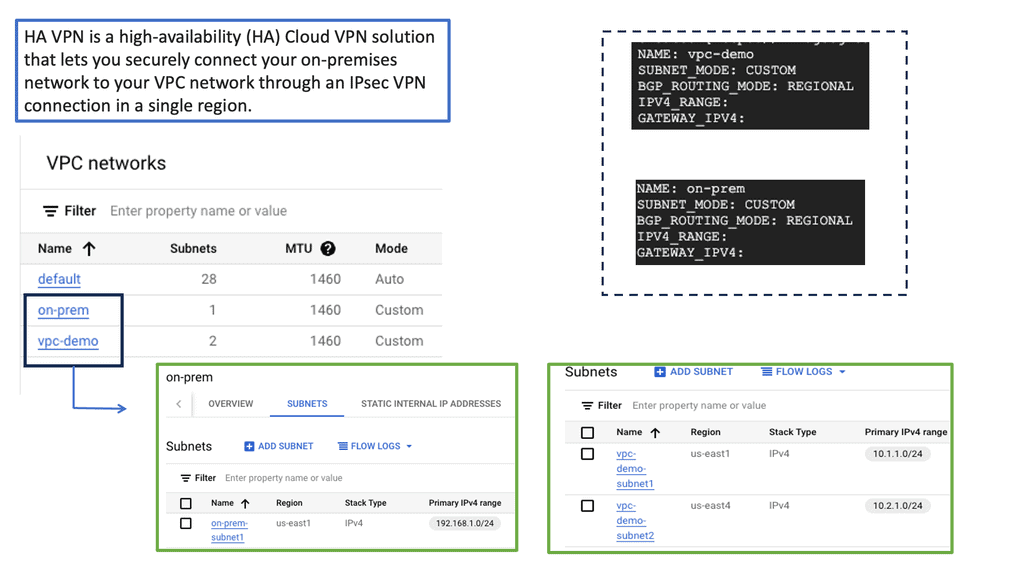
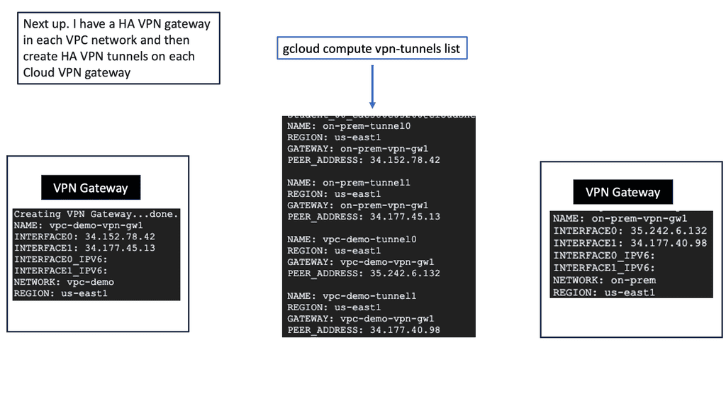
Dead Peer Detection (DPD) ( IPsec DPD ) is a mechanism whereby a device will send a liveness check to its IKEv2 peer to check that the peer is functioning correctly. It is helpful in high-availability IPsec designs when multiple gateways are available to build VPN tunnels between endpoints. There needs to be a mechanism to detect remote peer failure. IPsec control plane protocol ( IKE ) is based on a connectionless protocol called User Datagram Protocol ( UDP ).
As a result, IKE and IPsec cannot identify the loss of remote peers. IKE does not have a built-in mechanism to detect the availability of remote endpoints. Upon remote-end failure, previously established IKE and IPsec Security Associations ( SA ) remain active until their lifetime expires.
In addition, the lack of peer loss detection may result in network “black holes” as traffic continues to forward until SAs are torn down.
**Network Security**
Dead Peer Detection (DPD) is a network security protocol that detects when a previously connected peer is no longer available. DPD sends periodic messages to network peers and waits for a response. If the peer does not respond to the messages, the Dead Peer Detection IPSec protocol will assume the peer is no longer available and will take appropriate action.
DPD detects when a peer becomes unresponsive or fails to respond to messages. This can be due to several reasons, including the peer being taken offline, a connection issue, or a system crash. When a peer is detected as unresponsive, the DPD protocol will take action, such as disconnecting the peer or removing it from the network.
**DPD protocol**
To ensure a secure connection, the DPD protocol requires peers to authenticate themselves with each other. This helps to verify that the peers are indeed connected and that the messages being sent are legitimate. It also ensures malicious peers cannot disrupt the network by spoofing messages. In addition to authentication, DPD also uses encryption to protect data transmitted between peers. This helps to prevent data from being intercepted or tampered with.
Related: Before you proceed, you may find the following post helpful:
Understanding Dead Peer Detection
DPD serves as a mechanism to detect the availability of a remote peer in a Virtual Private Network (VPN) tunnel. It actively monitors the connection by exchanging heartbeat messages between peers. These messages confirm if the remote peer is still operational, allowing for timely reactions to any potential disruptions.
There are various ways to implement DPD, depending on the VPN protocol used. For instance, in IPsec VPNs, DPD can be configured through parameters such as detection timers and threshold values. Other VPN technologies, such as SSL/TLS, also offer DPD features that can be customized to meet specific requirements.
The advantages of utilizing DPD in VPN networks are numerous. Firstly, it aids in maintaining uninterrupted connectivity by promptly identifying and addressing any peer failures. This ensures that applications relying on the VPN tunnel experience minimal downtime. Additionally, DPD helps optimize network resources by automatically terminating non-responsive tunnels, freeing up valuable resources for other critical operations.
To harness the full potential of DPD, certain best practices should be followed. These include configuring appropriate detection timers and thresholds based on network conditions, regularly monitoring DPD logs for potential issues, and ensuring proper synchronization between peers to avoid false positives.
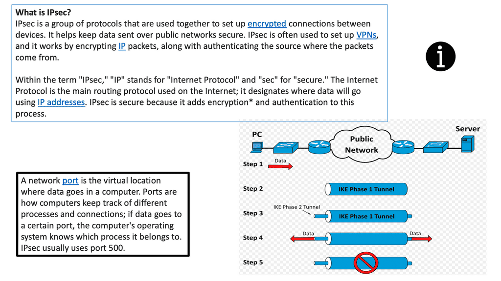
**A standard VPN**
A VPN permits users to securely expand a private network across an untrusted network. When IPsec VPNs are deployed, traffic is protected to ensure that no one can view the plaintext data; this is accomplished by encryption that provides confidentiality.
IPsec VPN accomplishes this by cryptographic hashing and signing the data exchanged, which provides integrity. Remember that a VPN must be established only with a chosen peer, achieved using mutual authentication.
Please be aware of the distinctions between a VPN using IPsec and a VPN using Multiprotocol Label Switching (MPLS). MPLS uses labels to differentiate traffic. MPLS labels are used to separate traffic, but unlike IPsec, they offer no confidentiality or integrity protection.
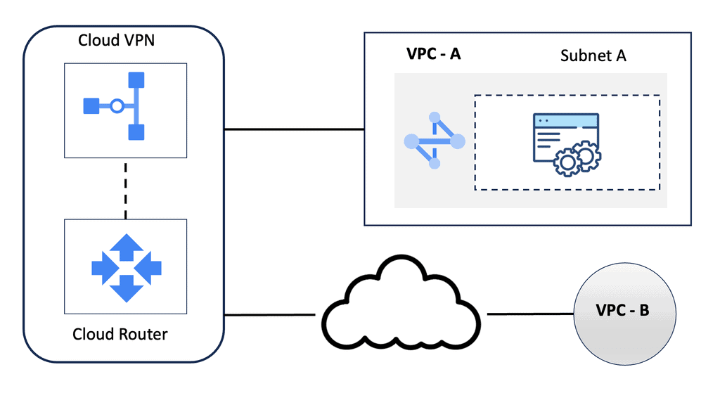
Guide: Site-to-site IPsec VPN
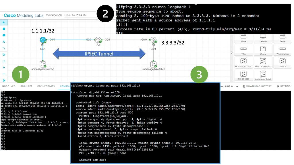
In the following lab, we have three routers. R2 is acting just as an interconnection point. It only has an IP address configuration on its interface. We have two Cisco IOS routers that use IPSec in tunnel mode. This means the original IP packet will be encapsulated in a new IP packet and encrypted before sending it out of the network. For this demonstration, I will be using the following three routers.
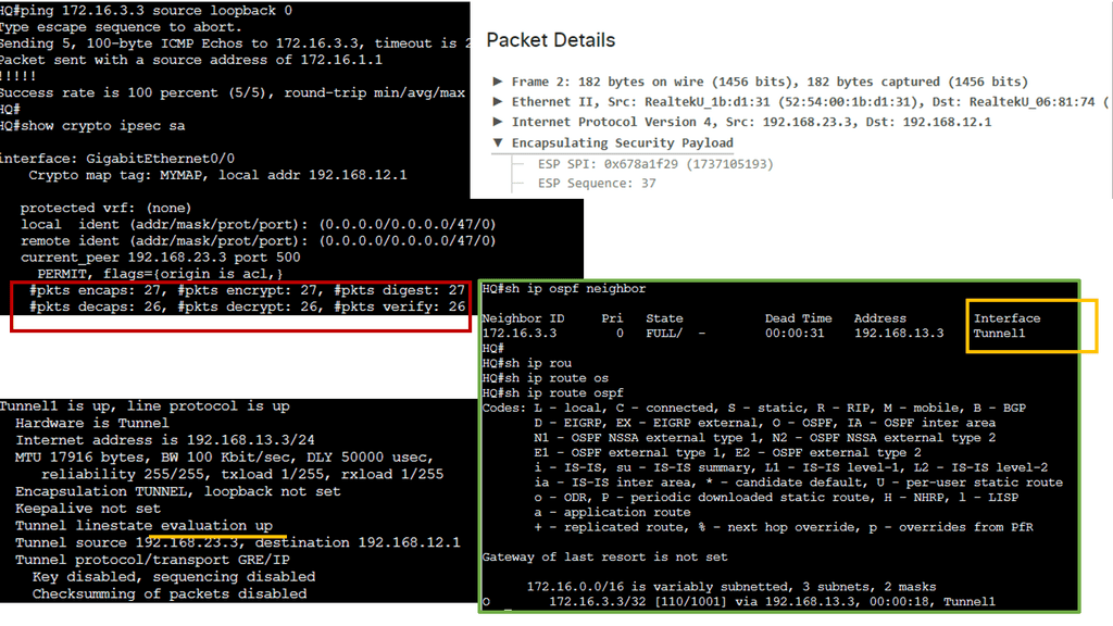
R1 and R3 each have a loopback interface behind them with a subnet. We’ll configure the IPsec tunnel between these routers to encrypt traffic from 1.1.1.1/32 to 3.3.3.3/32. Notice in the screenshot below that we can’t ping when the IPsec tunnel is not up. Once the IPsec tunnel is operational, we have reachability between the two peers.
IPsec VPN
IPSec VPN is a secure virtual private network protocol that encrypts data across different networks. It is used to protect the privacy of data transmitted over the Internet, as well as authenticate the identity of a user or device.
IPSec VPN applies authentication and encryption to the data packets traveling through a network. The authentication ensures that the data comes from a trusted source, while the encryption makes it unreadable to anyone who attempts to intercept the packets.
IPSec VPN is more secure than other VPN protocols, such as Point-to-Point Tunneling Protocol (PPTP) and Layer 2 Tunneling Protocol (L2TP). It can create a secure tunnel between two or more devices, such as computers, smartphones, or tablets. It also makes secure connections with other networks, such as the Internet. The following figure shows a generic IPsec diagram and some IPsec VPN details.
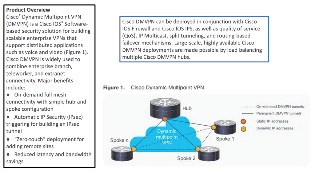
Example of a VPN solution – DMVPN.
With IPsec-based VPN implementations growing in today’s complex VPN landscape, scalability, simplicity, and ease of deployment have become more critical. DMVPN enhances traditional IPsec deployments by enabling on-demand IPsec tunneling and providing scalable and dynamic IPsec environments. I
IPsec solutions can be deployed with zero-touch using DMVPN, optimizing network performance and bandwidth utilization while reducing latency across the Internet. DMVPN has several DMVPN phases, such as DMVPN phase 1, that allow scaling IPsec VPN networks to offer a large-scale IPsec VPN deployment model.
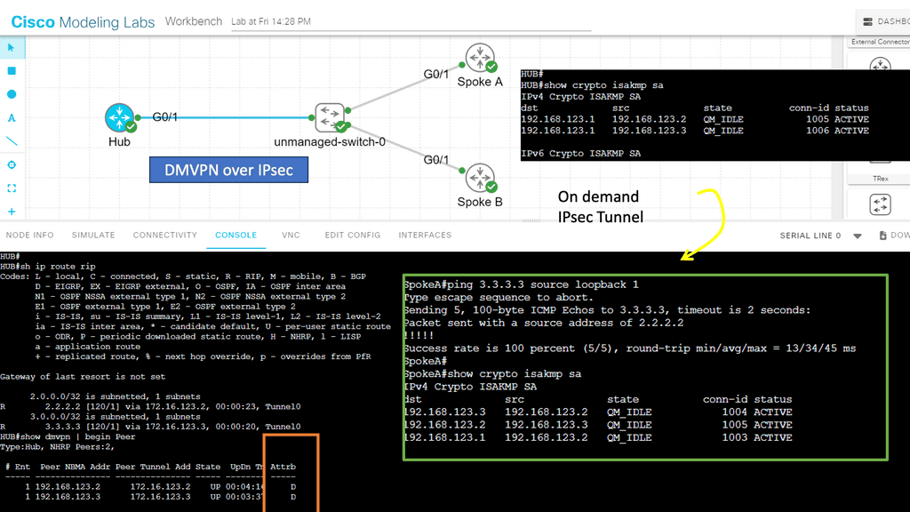
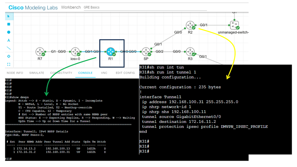
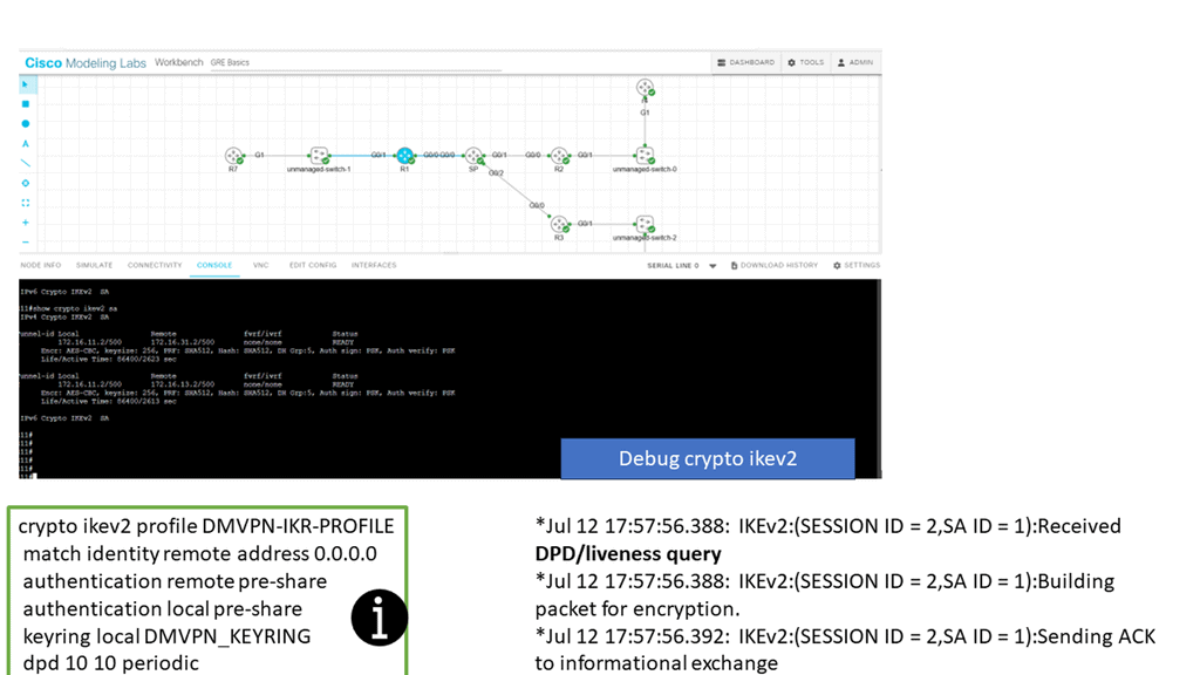
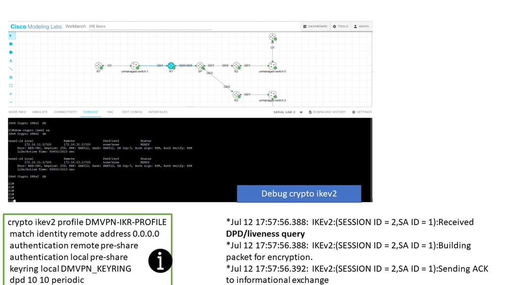
In the screenshot below, we have a DMVPN network. R1 is the Hub, and R2 and R3 are the spokes. So, we are running DMVPN phase 1. Therefore, we do not have dynamic spoke-to-spoke tunnels. We do, however, have dead peer detection configured.
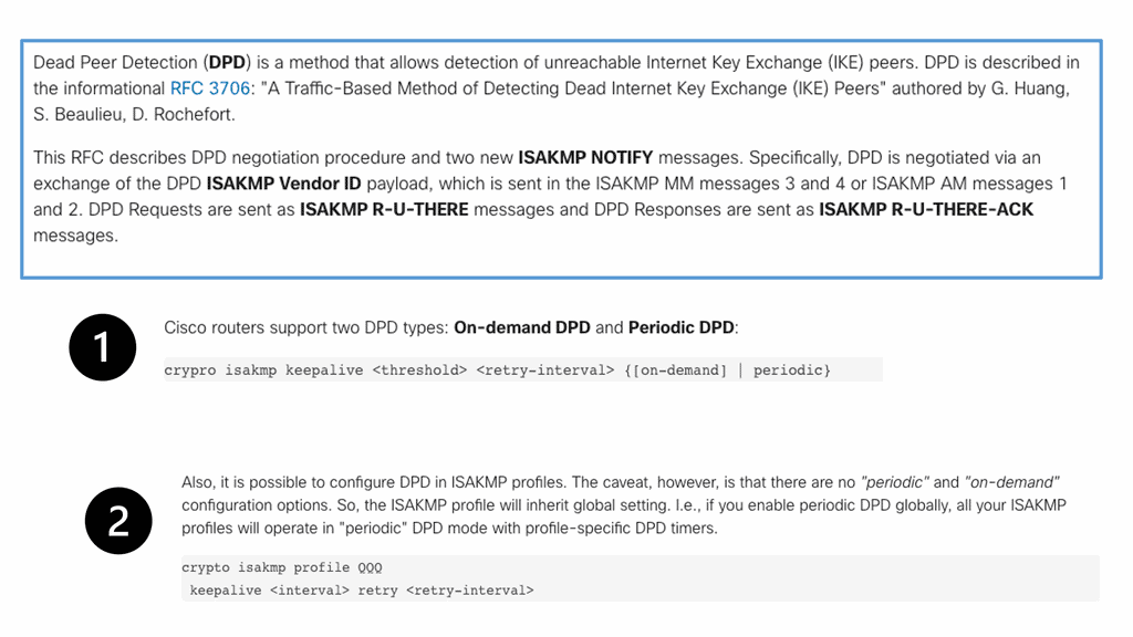
The command: show crypto ikev2 sa the likev2 security associasaiton on the DMVPN network. You will also notice the complete configuration of dead peer detection under the ikev2 profile. There are two DPD options: on-demand and periodic. Finally, we have the command: debug crypto ikev2 running on the spokes receiving a DPD liveness query from the hub.
IKE keepalive
IKE keepalive is a feature in IPsec VPNs that helps maintain secure connections between two endpoints. It sends periodic messages known as heartbeat messages, or keepalives, to both endpoints to ensure they are still connected. If one of the endpoints fails to respond, the keepalive will alert the other endpoint, allowing for a secure connection to be terminated before any data is lost.
IKE Keepalive is an essential feature of IPsec VPNs that ensures the reliability of secure connections between two endpoints. Using it, organizations can ensure that their secure connections remain active and that any transmitted data is not lost due to a connection failure.
A lightweight mechanism known as IKE Keepalive can be deployed with the following command: crypto isakmp keepalive 60 30. The gateway device regularly sends messages to the remote gateway and waits for a response.
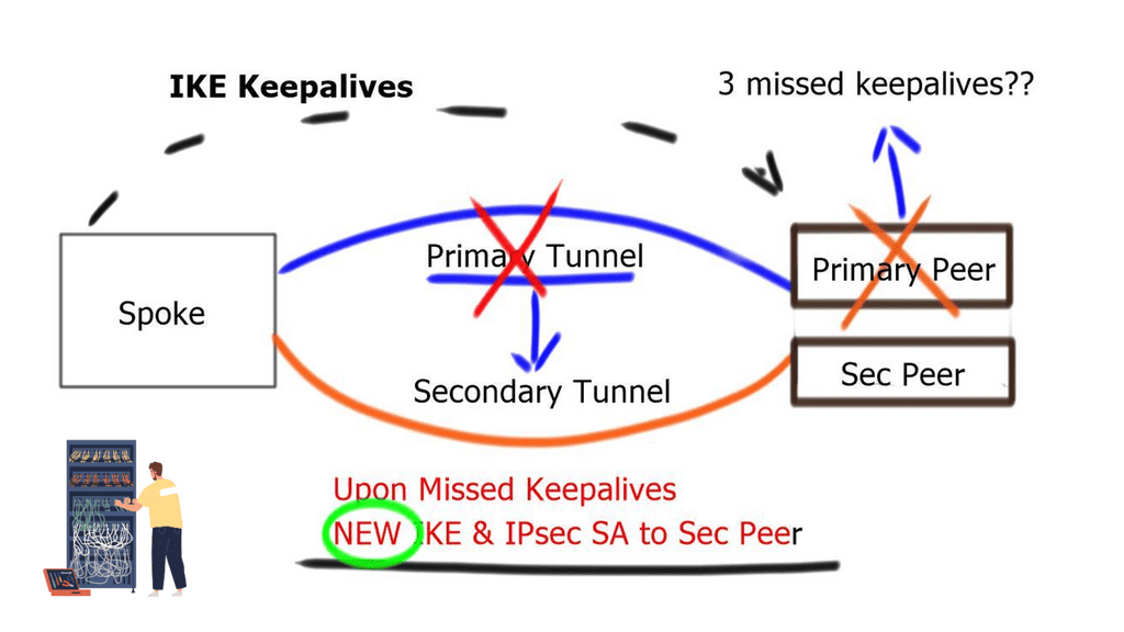
If three consecutive keepalive messages are unacknowledged, the Security Association ( SA ) to that peer is removed. IKE Keepalives help detect remote peer loss. However, it cannot detect whether remote networks behind the remote peer are reachable.
GRE tunnel keepalive
GRE Tunnel keepalive works with point-to-point tunnels, not Dynamic Multipoint VPN ( DMVPN ). Missed keepalives bring down the GRE tunnel interface, not Phase 1 or 2 SAs. Recovery is achieved with dynamic routing or floating static routing over the tunnels. Convergence is at the GRE level and not the IPsec level.
The tunnel is down upon remote end failure, but IPsec SA and ISAKMP SA will remain active. Eventually, SAs are brought down when their lifetime expires. The default lifetime of the IKE Policy is 86,400 seconds ( one day ). GRE Tunnel Keepalives are used only with crypto-based configurations and not profile-based configurations.
A key point: IPv6 high availability and dynamic routing protocols
If you dislike using keepalives, you can reconverge based on the dynamic routing protocol. Routing protocols are deployed over GRE tunnels and configured routing metric influence-preferred paths.
Failover is based on a lack of receipt of peer neighbor updates, resulting in dead-time expiration and neighbor tear-down. Like GRE keepalives, it is not a detection mechanism based on IKE or IPsec. Phases 1 and 2 will remain active and expire only based on lifetime.
Dead peer detection ( DPD )
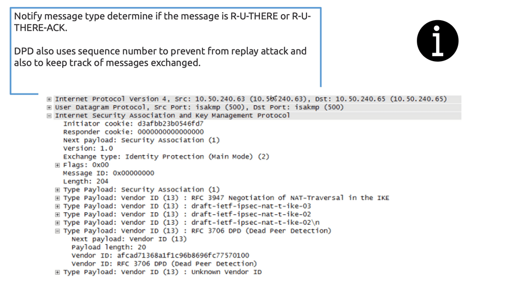
Dead peer detection is a traffic-based detection mechanism that uses IPsec traffic patterns to minimize the messages needed to confirm peer reachability. These checks are sent from each peer as an empty INFORMATIONAL exchange, which the corresponding receiving peer receives and retransmitted back to the initiating peer. The peer who initiated the liveness check can validate the returned packet by noting the message ID.
Unlike GRE or IKE keepalives, it does not send periodic keepalives. Instead, it functions because if IPsec traffic is sent and received, IPsec peers must be up and functioning. If not, no IPsec traffic will pass. On the other hand, if time passes without IPsec traffic, dead peer detection will start questioning peers’ liveliness.
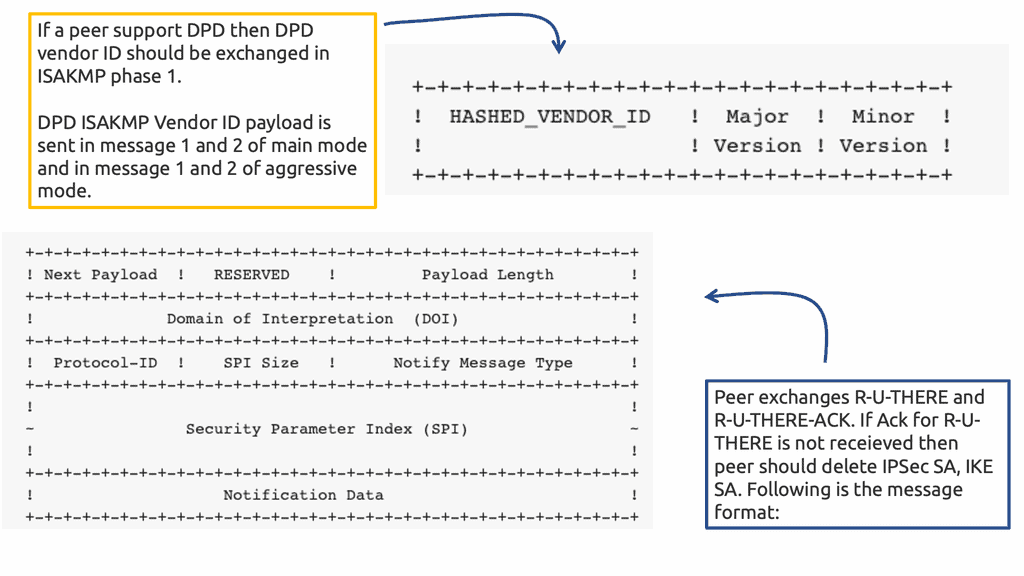
IPsec DPD must be supported and enabled by both peers. Negotiated during Phase 1, therefore, help before the tunnel is negotiated. You must clear the tunnels SA if you enable DPD after the tunnel is up. DPD parameters are not negotiated; they are locally significant.
If a device sends a liveness check to its peer and fails to receive a response, it will go into an aggressive retransmit mode, transmitting five DPD messages at a configured interval. If these transmitted DPD exchanges are not acknowledged, the peer device will be marked dead, and the IKEv2 SA and the child IPsec Security Associations will be torn down.
IPsec DPD is built into IKEv2, NOT IKEv1.
The IPSec DPD initiator is disabled and enabled by default in responder mode on IOS routers. However, it must be allowed as an initiator on BOTH ends so each side can detect the availability of the remote gateway. Unlike GRE keepalives, DPD brings down Phase 1 and 2 security associations.
Additional Details: Dead Peer Detection
Dead Peer Detection (DPD) is a network security protocol designed to detect a peer’s failure in an IPsec connection. It is a method of detecting when an IPsec-enabled peer is no longer available on the network. The idea behind the protocol is that, by periodically sending a packet to the peer, the peer can respond to the packet and prove that it is still active. The peer is presumed dead if no response is received within a specified time.
DPD is a critical feature of IPsec because it ensures a secure connection is maintained even when one of the peers fails. It is essential when both peers must always be available, such as for virtual private networks (VPNs). In such cases, DPD can detect when one of the peers has failed and automatically re-establish the connection with a new peer.
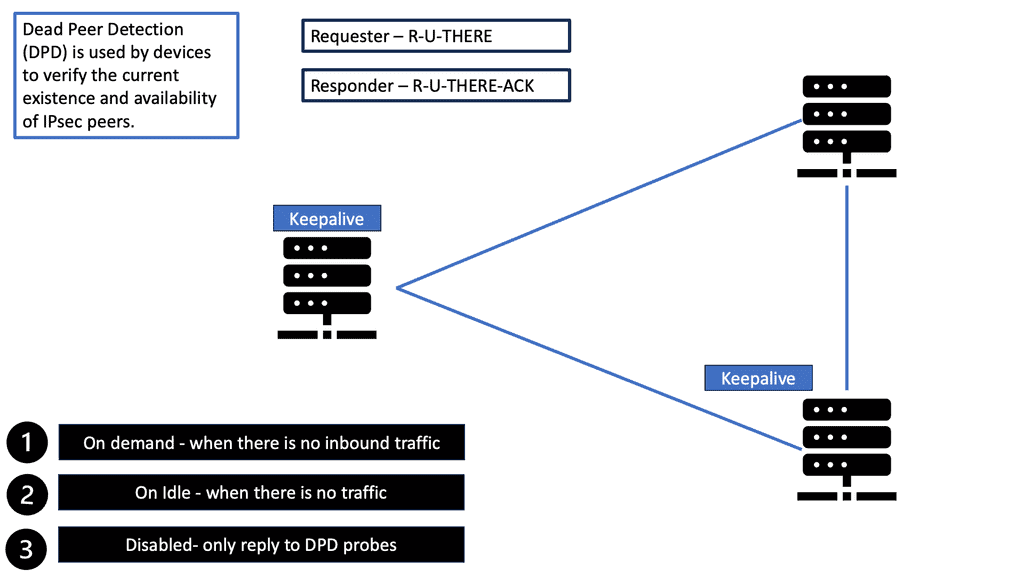
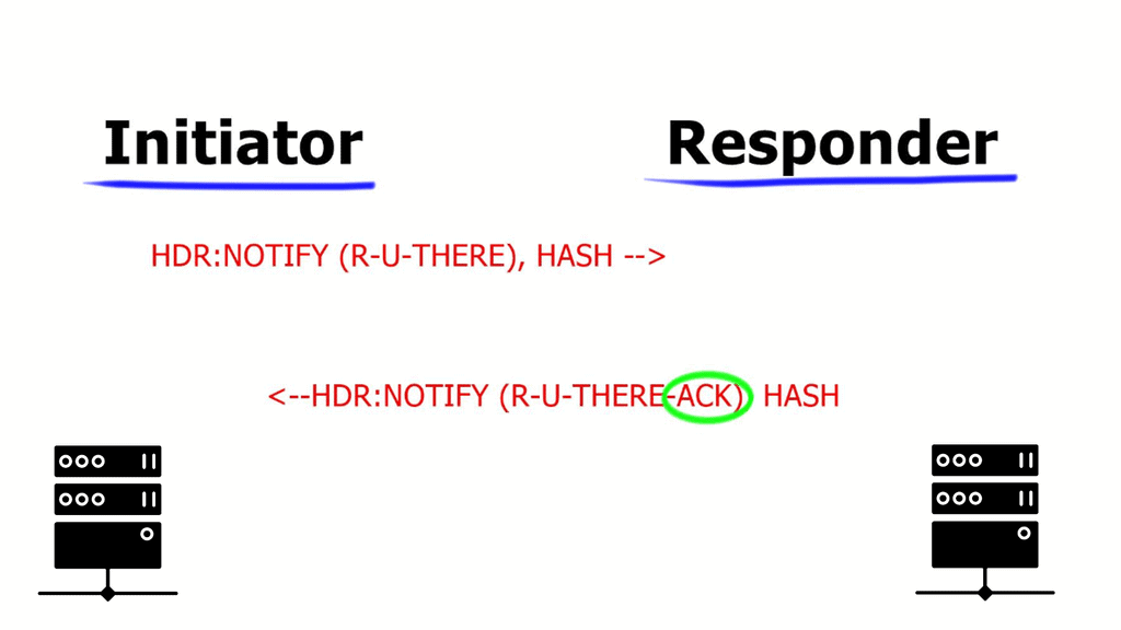
The DPD protocol sends a packet, known as an “R-U-THERE” packet, to the peer at periodic intervals. The peer then responds with an “R-U-THERE-ACK” packet. If the response is not received within a specific time, the peer is considered dead, and the connection is terminated.
**Dead Peer Detection**
When two routers establish an IPsec VPN tunnel between them, connectivity between the two routers can be lost for some reason. In most scenarios, IKE and IPsec do not natively detect a loss of peer connectivity, which results in network traffic being blackholed until the SA lifetime expires.
Dead Peer Detection (DPD) helps detect the loss of connectivity to a remote IPsec peer. When DPD is enabled in on-demand mode, the two routers check for connectivity only when traffic needs to be sent to the IPsec peer and the peer’s liveliness is questionable.
In such scenarios, the router sends a DPD R-U-THERE request to query the status of the remote peer. If the remote router does not respond to the R-U-THERE request, the requesting router starts to transmit additional R-U-THERE messages every retry interval for a maximum of five retries. After that, the peer is declared dead.
DPD is configured with the command crypto ikev2 dpd [interval-time] [retry-time] on-demand in the IKEv2 profile.
DPD and Routing Protocols
Generally, the interval time is set to twice that of the routing protocol timer (2 × 20), and the retry interval is set to 5 seconds. In essence, the total time is (2 × 20(routing-protocol)) + (5 × 5(retry-count)) = 65 seconds. This exceeds the hold time of the routing protocol and engages only when the routing protocol is not operating correctly.
In a DMVPN network, DPD is configured on the spoke routers, not the hubs, because of the CPU processing required to maintain the state for all the branch routers.
Closing Points on Dead Peer Detection (DPD)
Dead Peer Detection operates by sending periodic “heartbeat” messages between peers to confirm their presence and operational status. If a peer fails to respond within a specified timeframe, it is flagged as “dead” or unreachable. This process allows the network to quickly identify and address connectivity issues, ensuring that data packets are not sent into a void, which could lead to security risks and inefficient bandwidth use. The efficiency of DPD lies in its ability to swiftly detect and react to changes in network connectivity, thereby minimizing downtime and potential disruptions.
In secure communication environments, such as Virtual Private Networks (VPNs), maintaining an always-on connection is critical. DPD plays a vital role in these settings by ensuring that all connected peers are actively participating in the network. This not only enhances security by preventing unauthorized access but also optimizes resource allocation by eliminating the likelihood of sending data to inactive peers. The proactive nature of DPD is essential for maintaining the integrity and performance of secure network connections.
To effectively implement Dead Peer Detection, network administrators should consider several best practices. These include configuring appropriate timeout intervals and retry counts to balance between prompt detection and avoiding false positives. Regular testing and monitoring of DPD settings can also help in fine-tuning the system to match the specific needs of the network. Additionally, integrating DPD with other monitoring tools can provide a comprehensive overview of network health, allowing for quick identification and resolution of connectivity issues.