lisp-control-plane

LISP Data Plane | LISP Control plane


LISP Control Plane

LISP Control and LISP Data Plane

The networking landscape has undergone significant transformations over the years, with the need for efficient and scalable routing protocols becoming increasingly crucial. In this blog post, we will delve into the world of LISP (Locator/ID Separation Protocol) and explore its control plane, shedding light on its advantages to modern networks.

  • Understanding LISP Control Plane:

LISP, developed by the Internet Engineering Task Force (IETF), is a protocol that separates the location and identity of network devices. It provides a scalable solution for routing by decoupling the IP address (identity) from a device’s physical location (locator). The control plane of LISP plays a vital role in managing and distributing the mapping information required for efficient and effective routing.

We need a method to separate identity from location that offers many benefits. However, a single address field for identifying a device and determining where it is topologically located is not an optimum approach and presents many challenges with host mobility.

  • The LISP Protocol

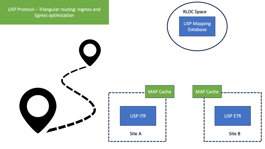
The LISP protocol offers an architecture that provides seamless ingress traffic engineering and moves detection without any DNS changes or agents on the host. A design that LISP can use would be active data center design. A vital concept of the LISP protocol is that end hosts operate similarly. Hosts’ IP addresses for tracking sockets and connections and sending and receiving packets do not change.


Before you proceed, you may find the following useful for pre-information:

  1. Observability vs Monitoring
  2. VM Mobility 
  3. What Is VXLAN
  4. LISP Hybrid Cloud
  5. Segment Routing
  6. Remote Browser Isolation


LISP Protocol

Key LISP Control Plane Discussion Points:


  • Introduction to the LISP Control Plane and what is involved.

  • Highlighting the details of the difference between the control vs data plane in a LISP network.

  • Step by step on the LISP control plane activity.

  • Step by step on the LISP data plane activity. 


  • A key point: Hands-on with LISP protocol

In this LISP product demonstration video, we will get hands-on and advanced with LISP configuration and debugging.Locator/ID Separation Protocol (LISP) architecture not only does the separation of device identity and location but also provides a Border Gateway Protocol (BGP)–free multihoming network, enables multi-address-family (AF) support, provides a highly scalable virtual private network (VPN) solution, and allows host mobility in data centers.


Hands on Video Series - Enterprise Networking | LISP Protocol Debug
Prev 1 of 1 Next
Prev 1 of 1 Next


Back to basics with the LISP

LISP: An IP overlay solution

LISP is an IP overlay solution that keeps the same semantics for IPv4 and IPv6 packet headers but operates two separate namespaces: one to specify the location and the other to determine the identity. A LISP packet has an inner IP header, which, like the headers of traditional IP packets, is for communicating endpoint to endpoint.

This would be from a particular source to a destination address. Then we have the outer IP header that provides the location the endpoint attaches to. The outer IP headers are also IP addresses.

Therefore, if an endpoint changes location, its IP address remains the same. It is the outer header that consistently gets the packet to the location of the endpoint. The endpoint identifier (EID) address is mapped to a router that the endpoint sits behind, which is understood as the routing locator (RLOC) in LISP terminology.


Benefits of LISP Control Plane:

1. Scalability: LISP’s control plane offers scalability advantages by reducing the size of the routing tables. With LISP, the mapping system maintains only the necessary information, allowing for efficient routing in large networks.

2. Mobility: The control plane of LISP enables seamless mobility as devices move across different locations. By separating the identity and locator, LISP ensures that devices maintain connectivity even when their physical location changes, reducing disruptions and enhancing network flexibility.

3. Traffic Engineering: LISP’s control plane allows for intelligent traffic engineering, enabling network operators to optimize traffic flow based on specific requirements. By leveraging the mapping information, routing decisions can be made dynamically, leading to efficient utilization of network resources.

4. Security: The LISP control plane offers enhanced security features. By separating the identity and locator, LISP helps protect the privacy of devices, making it harder for attackers to track or target specific devices. Additionally, LISP supports authentication mechanisms, ensuring the integrity and authenticity of the mapping information.


Implementing LISP Control Plane:

Several components are required to implement the LISP control plane, including the mapping system, the encapsulation mechanism, and the LISP routers. The mapping system is responsible for storing and distributing the mapping information, while the encapsulation mechanism ensures the separation of identity and locator. LISP routers play a crucial role in forwarding traffic based on the mapping information received from the control plane.

  • Real-World Use Cases:

LISP control plane has found applications in various real-world scenarios, including:

1. Data Centers: LISP helps optimize traffic flow within data centers, facilitating efficient load balancing and reducing latency.

2. Internet Service Providers (ISPs): LISP control plane enables ISPs to enhance their routing infrastructure, improving scalability and mobility support for their customers.

3. Internet of Things (IoT): As the number of connected devices continues to grow, the LISP control plane offers a scalable solution for managing the routing of IoT devices, ensuring seamless connectivity even as devices move.

Control Plane vs Data Plane

The LISP data plane

LISP protocol
LISP protocol and the data plane functions.


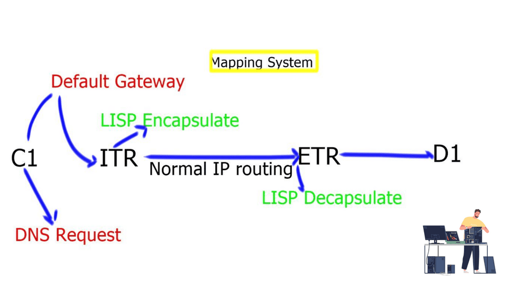
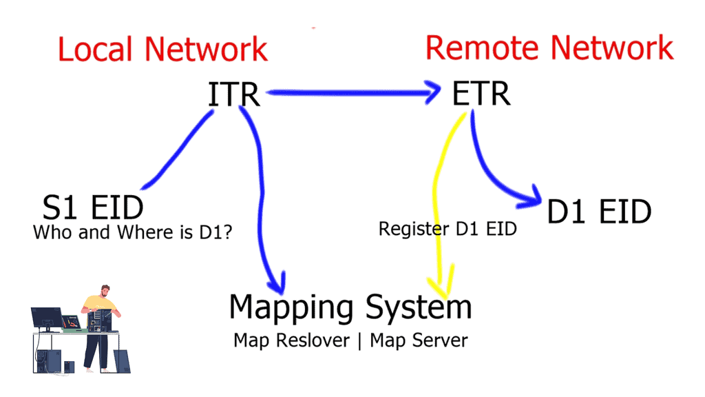
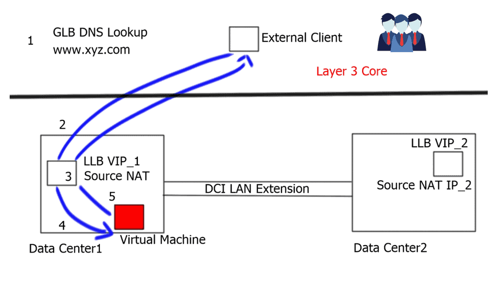
  1. Client C1 is located in a remote LISP-enabled site and wants to open a TCP connection with D1, a server deployed in a LISP-enabled Data Center. C1 queries through DNS the IP address of D1, and an A/AAAA record is returned. The address returned is the destination Endpoint Identifier ( EID ), and it’s non-routable. EIDs are IP addresses assigned to hosts.-Client C1 realizes this is not an address on its local subnet and steers the traffic to its default gateway, a LISP-enabled device. This triggers the LISP control-plane activity.
  2. The LISP control plane is triggered only if the lookup produces no results or if the only available match is a default route. This means that a Map-Request ( from ITR to the Mapping system ) is sent only when the destination is not found.
  3. The ITR receives its EID-to-RLOC mapping from the mapping system and updates its local map-cache that previously did not contain the mapping. The local map cache can be used for future communications between these endpoints.
  4. The destination EID will be mapped to several RLOC ( Routing Locator ), which will identify the ( Egress Tunnel Router ) ETRs at the remote Data Center site. Each entry has associated priorities and weights with loading balance, influencing inbound traffic towards the RLOC address space. The specific RLOC is selected on a per-flow basis based on the 5-tuple hashing of the original client’s IP packet.
  5. Once the controls are in place, the ITR performs LISP encapsulation on the original packets and forwards the LISP encapsulated packet to one ( two or more if load balancing is used ) of the RLOCs of the Data Center ETRs. RLOC prefixes are routable addresses.-The destination ETR receives the packet, decapsulates, and sends it towards the destination EID.
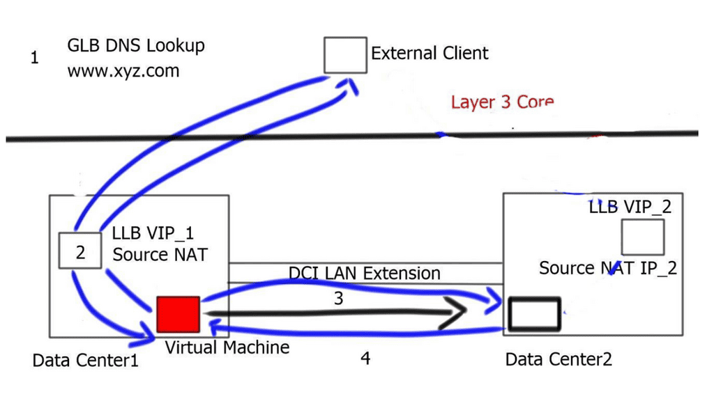
 

LISP control plane

LISP Control plane
LISP Control plan


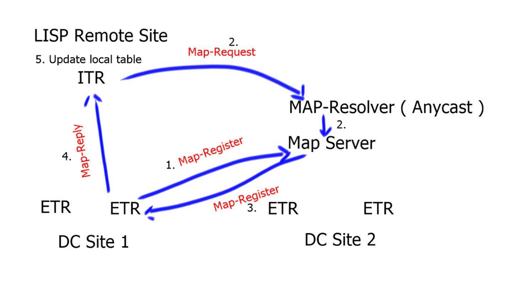
  1. The destination ETRs register their non-routable EIDs to the Map-Server using a Map-Register message. This is done every 60 seconds.If the ITR does not have a local mapping for the remote EID-RLOC mapping, it will send a Map-Request message to the Map-Resolver. Map-Requests should be rate-limited to avoid denial of service attacks.
  2. The Map-Resolver then forwards the request to the authoritative Map-Server. The Map-Resolver and Map-Server could be the same device. The Map resolver could also be an anycast address.
  3. The Map-Server then forwards the request to the last registered ETR. The ETR looks at the destination of the Map-Request and compares it to its configured EID-to-RLOC database. A match triggers the ETR to directly reply to the ITR with a Map-Reply containing the requested mapping information. Map-Replies are sent on the underlying routing system topology. On the other hand, if there is no match, the Map-Request is dropped.
  4. When the ITR receives the Map-Reply containing the mapping information, it will update its local EID-to-RLOC map cache. All subsequent flows will go forward without the mapping systems integration.


control plane vs data plane

LISP networking

LISP Protocol and VM Mobility


vm mobility


LISP Protocol and VM Mobility

The networking world is constantly evolving, with new technologies emerging to meet the demands of an increasingly connected world. One such technology that has gained significant attention is the LISP protocol. In this blog post, we will delve into the intricacies of the LISP protocol, exploring its purpose, benefits, and how it bridges the gap in modern networking and its use case with VM mobility.

  • What is LISP?

LISP, which stands for Locator/ID Separation Protocol, is a network protocol that separates the identity of a device from its location. Unlike traditional IP addressing schemes, which rely on a tightly coupled relationship between the IP address and the device’s physical location, LISP separates these two aspects, allowing for more flexibility and scalability in network design.

  • How Does LISP Work

Locator Identity Separation Protocol ( LISP ) provides a set of functions that allow Endpoint identifiers ( EID ) to be mapped to an RLOC address space. The mapping between these two endpoints offers the separation of IP addresses into two numbering schemes ( similar to the “who” and the “where” analogy ), offering many traffic engineering and IP mobility benefits for the geographic dispersion of data centers beneficial for VM mobility.

  • LISP Components

The LISP protocol operates by creating a mapping system that separates the device’s identifier, the Endpoint Identifier (EID), from its location, the Routing Locator (RLOC). This separation is achieved using a distributed database called the LISP Mapping System (LMS), which maintains the mapping between EIDs and RLOCs. When a packet is sent to a destination EID, it is encapsulated and routed based on the RLOC, allowing for efficient and scalable communication.


Before you proceed, you may find the following posts helpful:

  1. LISP Hybrid Cloud 
  2. LISP Control Plane
  3. Triangular Routing
  4. Active Active Data Center Design
  5. Application Aware Networking


VM Mobility

Key LISP Protocol Discussion Points:


  • Introduction to the LISP Protocol and what is involved.

  • Highlighting the details of the LISP traffic flow.

  • Technical details on LAN extension considerations. 

  • LISP Extended Subnet and Across Subnet.


  • A key point: Video on LISP configuration.

In this video, we will have a look at LISP configuration. This can be considered the first step before you get into the more advanced features of LISP and VM mobility. From its inception, the LISP protocol has been an open standard protocol that interoperates across various platforms and is incrementally deployable on top of any transport.

LISP’s flexibility has led to its application in every part of today’s modern network, from the data center to the enterprise WAN to the enterprise campus to the service provider edge and the core. The following will help you understand a LISP hybrid cloud implementation.


Hands on Video Series - Enterprise Networking | LISP Configuration Intro
Prev 1 of 1 Next
Prev 1 of 1 Next


Back to basics with the Virtual Machine (VM).

Virtualization

Virtualization can be applied to subsystems such as disks and a whole machine. A virtual machine (VM) is implemented by adding a software layer to an actual device to sustain the desired virtual machine’s architecture. In general, a virtual machine can circumvent real compatibility and hardware resource limitations to enable a more elevated degree of software portability and flexibility.

n the dynamic world of modern computing, the ability to seamlessly move virtual machines (VMs) between different physical hosts has become a critical aspect of managing resources and ensuring optimal performance. This blog post explores VM mobility and its significance in today’s rapidly evolving computing landscape.

VM mobility refers to transferring a virtual machine from one physical host to another without disrupting operation. This capability is made possible through virtualization technologies such as hypervisors, which enable the abstraction of hardware resources and allow multiple VMs to coexist on a single physical machine.

LISP and VM Mobility

The Locator/Identifier Separation Protocol (LISP) is an innovative networking architecture that decouples the identity (Identifier) of a device or VM from its location (Locator). By separating the two, LISP provides a scalable and flexible solution for VM mobility.

How LISP Enhances VM Mobility:

1. Improved Scalability:

LISP introduces a level of indirection by assigning Endpoint Identifiers (EIDs) to VMs. These EIDs act as unique identifiers, allowing VMs to retain their identity even when they are moved to different locations. This enables enterprises to scale their VM deployments without worrying about the limitations imposed by the underlying network infrastructure.

2. Seamless VM Mobility:

LISP simplifies moving VMs by abstracting the location information using Routing Locators (RLOCs). When a VM is migrated, LISP updates the mapping between the EID and RLOC, allowing the VM to maintain uninterrupted connectivity. This eliminates the need for complex network reconfigurations, reducing downtime and improving overall agility.

3. Load Balancing and Disaster Recovery:

LISP enables efficient load balancing and disaster recovery strategies by providing the ability to distribute VMs across multiple physical hosts or data centers. With LISP, VMs can be dynamically moved to optimize resource utilization or to ensure business continuity in the event of a failure. This improves application performance and enhances the overall resilience of the IT infrastructure.

4. Interoperability and Flexibility:

LISP is designed to be interoperable with existing network infrastructure, allowing organizations to gradually adopt the protocol without disrupting their current operations. It integrates seamlessly with IPv4 and IPv6 networks, making it a future-proof solution for VM mobility.


Basic LISP Traffic flow

A device ( S1 ) initiates a connection and wants to communicate with another external device ( D1 ). D1 is located in a remote network. S1 will create a packet with the EID of S1 as the source IP address and the EID of D1 as the destination IP address. As the packets flow to the network’s edge on their way to D1, it is met by an Ingress Tunnel Router ( ITR ).

The ITR maps the destination EID to a destination RLOC and then encapsulates the original packet with an additional header with the source IP address of the ITR RLOC and the destination IP address of the RLOC of an Egress Tunnel Router ( ETR ). The ETR is located on the remote site next to the destination device D1.

LISP protocol

The magic is how these mappings are defined, especially regarding VM mobility. There is no routing convergence, and any changes to the mapping systems are unknown to the source and destination hosts. We are offering complete transparency.


LISP Terminology

LISP namespaces:

LSP Name Component

LISP Protocol Description 

End-point Identifiers  ( EID ) Addresses

The EID is allocated to an end host from an EID-prefix block. The EID associates where a host is located and identifies endpoints. The remote host obtains a destination the same way it obtains a normal destination address today, for example through DNS or SIP. The procedure a host uses to send IP packets does not change. EIDs are not routable.

Route Locator ( RLOC ) Addresses

The RLOC is an address or group of prefixes that map to an Egress Tunnel Router ( ETR ). Reachability within the RLOC space is achieved by traditional routing methods. The RLOC address must be routable.


LISP site devices:

LISP Component

LISP Protocol Description 

Ingress Tunnel Router ( ITR )

An ITR is a LISP Site device that sits in a LISP site and receives packets from internal hosts. It in turn encapsulates them to remote LISP sites. To determine where to send the packet the ITR performs an EID-to-RLOC mapping lookup. The ITR should be the first-hop or default router within a site for the source hosts.

Egress Tunnel Router ( ETR )

An ETR is a LISP Site device that receives LISP-encapsulated IP packets from the Internet, decapsulates them, and forwards them to local EIDs at the site. An ETR only accepts an IP packet where the destination address is the “outer” IP header and is one of its own configured RLOCs. The ETR should be the last hop router directly connected to the destination.


LISP infrastructure devices:

LISP Component Name

LISP Protocol Description

Map-Server ( MS )

The map server contains the EID-to-RLOC mappings and the ETRs register their EIDs to the map server. The map-server advertises these, usually as an aggregate into the LISP mapping system.

Map-Resolver ( MR )

When resolving EID-to-RLOC mappings the ITRs send LISP Map-Requests to Map-Resolvers. The Map-Resolver is typically an Anycast address. This improves the mapping lookup performance by choosing the map-resolver that is topologically closest to the requesting ITR.

Proxy ITR ( PITR )

Provides connectivity to non-LISP sites. It acts like an ITR but does so on behalf of non-LISP sites.

Proxy ETR ( PETR )

Acts like an ETR but does so on behalf of LISP sites that want to communicate to destinations at non-LISP sites.


VM Mobility

LISP Host Mobility

LISP VM Mobility ( LISP Host Mobility ) functionality allows any IP address ( End host ) to move from its subnet to either a) a completely different subnet, known as “across subnet,” or b) to an extension of its subnet in a different location, known as “extended subnet” – while keeping its original IP address.

When the end host carries its own Layer 3 address to the remote site, and the prefix is the same as the remote site, it is known as an “extended subnet.” Extended subnet mode requires a Layer 2 LAN extension. On the other hand, when the end hosts carry a different network prefix to the remote site, it is known as “across subnets.” When this is the case, a Layer 2 extension is not needed between sites.


LAN extension considerations

LISP does not remove the need for a LAN extension if a VM wants to perform a “hot” migration between two dispersed sites. The LAN extension is deployed to stretch a VLAN/IP subnet between separate locations. LISP complements LAN extensions with efficient move detection methods and ingress traffic engineering.

LISP works with all LAN extensions – whether back-to-back vPC and VSS over dark fiber, VPLS, Overlay Transport Virtualization ( OTV ), or Ethernet over MPLS/IP. LAN extension best practices should still be applied to the data center edges. These include but are not limited to – End-to-end Loop Prevention and STP isolation.

A LISP site with a LAN extension extends a single site across two physical data center sites. This is because the extended subnet functionality of LISP makes two DC sites a single LISP site. On the other hand, when LISP is deployed without a LAN extension, a single LISP site is not extended between two data centers, and we end up having separate LISP sites.


LISP extended subnet

VM mobility
VM mobility: LISP protocol and extended subnets


The LAN extension technology must filter Hot Standby Router Protocol ( HSRP ) HELLO messages across the two data centers to avoid asymmetric traffic handling. This creates an active-active HSRP setup. HSRP localization optimizes egress traffic flows. LISP optimizes ingress traffic flows.

The default gateway and virtual MAC address must remain consistent in both data centers. This is because the moved VM will continue to send to the same gateway MAC address. This is accomplished by configuring the same HSRP gateway IP address and group in both data centers. When an active-active HSRP domain is used, re-ARP is not needed during mobility events.

The LAN extension technology must have multicast enabled to support the proper operation of LISP. Once a dynamic EID is detected, the multicast group IP addresses send a map-notify message by the xTR to all other xTRs. The multicast messages are delivered leveraging the LAN extension.


LISP across subnet 

VM mobility
VM mobility: LISP protocol across Subnets


LISP across subnets requires the mobile VM to access the same gateway IP address, even if they move across subnets. This will prevent egress traffic triangulation back to the original data center. This can be achieved by manually setting the vMAC address associated with the HSRP group to be consistent across sites.

Proxy ARP must be configured under local and remote SVIs to handle new ARP requests generated by the migrated workload correctly.
With this deployment, there is no need to deploy a LAN extension to stretch VLAN/IP between sites. This is why it is considered to address “cold” migration scenarios, such as Disaster Recovery ( DR ) or cloud bursting and workload mobility according to demands.


Benefits of LISP:

1. Scalability: By separating the identifier from the location, LISP provides a scalable solution for network design. It allows for hierarchical addressing, reducing the size of the global routing table and enabling efficient routing across large networks.

2. Mobility: LISP’s separation of identity and location mainly benefits mobile devices. As devices move between networks, their EIDs remain constant while the RLOCs are updated dynamically. This enables seamless mobility without disrupting ongoing connections.

3. Multihoming: LISP allows a device to have multiple RLOCs, enabling multihoming capabilities without complex network configurations. This ensures redundancy, load balancing, and improved network reliability.

4. Security: LISP provides enhanced security features such as cryptographic authentication and integrity checks, ensuring the integrity and authenticity of the mapping information. This helps in mitigating potential attacks, such as IP spoofing.

Applications of LISP:

1. Data Center Interconnection: LISP can interconnect geographically dispersed data centers, providing efficient and scalable communication between different locations.

2. Internet of Things (IoT): With the exponential growth of IoT devices, LISP offers an efficient solution for managing these devices’ addressing and communication needs, ensuring seamless connectivity in large-scale deployments.

3. Content Delivery Networks (CDNs): LISP can optimize content delivery by allowing CDNs to cache content closer to end-users, reducing latency and improving overall performance.

Conclusion:

The LISP protocol is a revolutionary technology that addresses the challenges of scalability, mobility, multi-homing, and security in modern networking. Its separation of identity and location opens up new possibilities for efficient and flexible network design. With its numerous benefits and versatile applications, LISP is poised to play a pivotal role in shaping the future of networking.


lisp protocol

lisp-control-plane

Triangular Routing

Triangular Routing

LISP, which stands for Locator/ID Separation Protocol, is a groundbreaking networking protocol that has gained significant attention in recent years. In traditional networking, the IP address plays a dual role as both a locator and an identifier. However, LISP introduces a new approach by separating the two, allowing for more efficient and scalable routing. In this blog post, we will delve into the world of LISP and specifically explore the concept of triangular routing.

Triangular routing is a fundamental concept within LISP that plays a crucial role in its operation. In traditional routing, packets travel from the source to the destination in a direct path. However, LISP introduces a different approach by employing a triangular routing scheme. In this scheme, packets take a detour through a mapping system known as the Mapping System (MS).

The MS acts as an intermediary, allowing the encapsulation and decapsulation of packets as they traverse the LISP-enabled network. This triangular path not only provides flexibility but also enables various LISP functionalities, such as mobility and traffic engineering.

Table of Contents

Highlights: Triangular Routing

Ingress Site Selection

An essential requirement for business continuity is to support distributed applications. Different types of applications, be they legacy or nonlegacy, will provide particular challenges for ingress site selection. One of the main challenges designers face is workload virtualization between different geographic locations. Workload virtualization requires location independence for server resources and the ability to move these resources from one geographic location to another. This is where triangular routing comes into play.

The LISP protocol

What is triangular routing? Triangular routing is a method for transmitting packets of data in communications networks. It uses a form of routing that sends a packet to a proxy system before transmission to the intended destination. The LISP Protocol used as an Internet locator can be used as a proxy.

Related: Before you proceed, you may find the following posts helpful for pre-information:

  1. Network Security Components
  2. LISP Hybrid Cloud
  3. Remote Browser Isolation
  4. Dynamic Workload Scaling
  5. Active Active Data Center Design
  6. Identity Security

Triangular Routing

Key Triangular Routing Discussion Points:


  • Introduction to triangular routing and what is involved.

  • Highlighting the details of the LISP traffic flow.

  • Technical details on Ingress and Egress traffic flows.

  • Scenario with a DC extension use case.

  • LISP Host mobility solution. 


Virtualized Workload Mobility

Virtualized Workload Mobility allows live migration between “Twin” data centers and presents several challenges. Firstly, it brings the challenge of route optimization once the workload has moved to the new location. When virtual machines are migrated between data centers, the traffic flow for client-server may become suboptimal, leading to application performance degradation.

How do existing and new connections get directed to the new location? Traditional methods, such as Route Health Injection ( RHI ) and DNS, are available but don’t suit all requirements. They can place unnecessary workloads over the data center interconnect link ( DCI ), creating a triangular routing effect discussed below.

A Key Point: Knowledge Check 

Back to Basics: Triangular Routing

IP Routing.

A router’s primary function is to move an IP packet from one network to a different network. Routers try to select the best loop-free path in a network that forwards a packet to its destination IP address. A router understands nonattached networks through static configuration or dynamic IP routing protocols. So we have two routing protocols, static and dynamic.

Dynamic IP routing protocols distribute network topology information between routers and provide updates without intervention when a topology change occurs. On the other hand, IP routing with static routes only accommodates topology changes well and can burden network engineers depending on the network size.

IP Routing example
Diagram: IP routing example. The source is Study CCNA.

A network routing technique

So, what is triangular routing? Triangular routing is a network routing technique that involves sending traffic through three or more points on the network. It is often used to increase the network’s reliability, security, or performance by reducing the load on any single point. In triangular routing, the data is sent from the source node to a middle node and then to the destination node. Depending on the network configuration, the central node may be a router, switch, or hub.

Avoid congestion

Triangular routing is a common technique on the Internet. It is used to avoid congestion and increase reliability. When a connection is established between two nodes, the traffic is sent from the source to the middle node via a shorter route. If the connection between the central node and the destination node is interrupted, the data can be re-routed through another node. This ensures the data is delivered to the destination without interruption.

Triangular routing is also used in private networks, such as corporate networks. It reduces the load on a single point, reduces latency, and increases the network’s security. In addition, each node in the triangular routing is configured with different routing protocols, making it difficult for intruders to penetrate the network.

Triangular routing is a reliable and secure routing technique that can be used to improve the performance of a network. It can be used to avoid congestion and increase reliability by routing data through multiple points on the network. The following figure shows an example of triangular routing.

Hair-pinning & Triangular routing – Ingress and Egress traffic flows.

Triangular routing

  1. The external client queries its configured DNS server. The Global Load Balancing ( GLB ) device receives the request, which is authoritative for the queried domain. The GLB responds with the VIP_1 address of the local Load Balancer ( LLB ) in DC1. The VIP_1 represents the application in DC1.
  2. Traffic gets directed toward the active LLB in DC1.
  3. The LLB performs a Source-NAT translation. Source-NAT changes the source IP address to the internal IP address of the LLB. This enables return traffic to be routed back through the correct Load balancer. This step is necessary to retain existing established sessions.
  4. The Virtual Machine ( VM ) receives the packet and replies with the destination address of the Local Load Balancer ( due to Source-NAT ).
  5. The LLB performs reverse translation and returns the packet to the external client.

Let’s assume that DC1 is overutilized and the network administrator wants to move the VM from DC1 to DC2. This move will be a hot move, a “live migration,” so all established sessions must remain intact. This is mainly because of the presence of stateful devices and the fact that we are not stretching the state of these stateful devices between the two data centers.

There is also a requirement for a LAN extension, such as OTV or vPC, between the two data centers. The LAN extension stretches VLANs and the layer 2 traffic between the two data centers.

triangular routing

  1. The client-server flows are still directed to VIP_1 from the global load balancers, as there have been no changes to site selection for existing connections. We are traversing the same stateful device as in the earlier example.
  2. The local load balancer performs Source-NAT and changes the source IP address to its inside address.
  3. The packet can reach the moved VM by leveraging the L2 LAN extension between both DCs.
  4. Any existing or new sessions using the VIP_1 of DC1 will follow the suboptimal path through DC1 to get to DC2.

You would hope there can be immediate changes to DNS and any new sessions ingress to DC2. This would follow the optimum path to the VIP_2, and egress traffic would follow the local gateway in DC2.

Triangular routing: The challenge

The main problem with this approach is that it works for only name-based connections, and previously established connections are hairpinned. The hair-pinning effect implies that there have been active connections to the VIP_1 ( old address ) and some new connections to the VIP_2 in the second data center for some time. Hair-pinning can put an additional load on the DCI and create a triangular routing effect.

The Solution? Locator Identity Separation Protocol ( LISP )

A new routing architecture called Locator Identity Separation Protocol ( LISP ) was developed to overcome the challenges of workload mobility and triangular routing previously discussed. LISP overcomes the problems faced with route optimization when workloads migrate. It creates a new paradigm by splitting the device identity, an Endpoint Identifier ( EID ), and its location, known as its Routing Locator ( RLOC ), into two different numbering spaces.

This means we have a separate protocol representing where and who you are. The existing number scheme based on IP does not offer this flexibility, and both roles ( who and where ) are represented by one address.

LISP Control plane
LISP Control plane

Additional information on the LISP protocol 

RFC 6830, LISP is described as a routing and addressing architecture for the Internet Protocol. The LISP routing architecture addressed scalability, multihoming, inter-site traffic engineering, and mobility.

Internet addresses today combine location (how a device is connected to the network) and identity semantics into a single 32-bit or 128-bit number. In LISP, the location is separated from the identity. LISP allows you to change your location in a network (your network layer locator), but your identity remains the same (your network layer identifier).

A LISP separates the identifiers of end users from the routing locators used to reach them. The LISP routing architecture design separates device identity – endpoint identification (EID) – from its location – routing locator (RLOC). To further understand how LISP does the locator/ID separation, it is essential to first learn about the architectural components of LISP. The following are some of the functions or features that form the LISP architecture:

LISP Components
Diagram: LISP Components. Source Cisco Press.


LISP Host Mobility

LISP Host Mobility provides an automated solution that enables IP end-points, for example, Virtual Machines ( VM ), to change location while keeping their assigned IP address. As a result, the LISP detection and mapping system guarantees optimal routing between clients and the IP end-points that moved. The critical point to note is that it’s an automated system.

There is no need to change DNS once the VM moves to the new location. The LISP control plane does not make any changes to DNS and does not require any agents installed on the clients. It’s completely transparent.

LISP VM-mobility provides a transparent solution to end hosts and guarantees optimal path routing to the moving endpoints. It decouples the identity from the topology but creates two separate namespaces, RLOC and EID. The RLOCs remain associated with the topology and are reachable via traditional routing methods. The EID, which describes the end host, can dynamically change location and associate with different RLOCs. This allows the End-point Identifier space to be mobile without impacting the routing interconnecting the locator’s IP space.

LISP VM-Mobility solution:

  • VM migrations are automatically detected by the LISP Tunnel Router ( xTR ). This is accomplished by comparing the source in the IP header of traffic received from the hosts against a range of configured prefixes allowed to roam.
  • No changes are required to DNS or to install any agents. Transparent to end-users.
  • Once the move is detected, the mappings between EIDs and RLOCs are updated by the new xTR.
  • Updating the RLOC-to-EID mappings allows traffic to be redirected to the new locations without causing any updates or churn in the underlying routing. Transparent to the core.

Additional information

  • Load Balancing:

By distributing data packets across multiple paths, triangular routing helps balance the network load. This ensures that no single path becomes overwhelmed with traffic, preventing congestion and optimizing network performance. Load balancing improves network efficiency and minimizes latency, resulting in faster data transmission.

  • Fault Tolerance:

One of the critical advantages of triangular routing is its fault tolerance capabilities. In the event of a link failure or network congestion on one path, the other two paths can still carry the data packets to their destination. This redundancy ensures that the network remains operational despite adverse conditions, reducing the risk of data loss and maintaining uninterrupted connectivity.

Benefits of Triangular Routing:

1. Improved Network Performance: Triangular routing enhances network performance by distributing traffic across multiple paths, reducing congestion, and minimizing latency.

2. Enhanced Reliability: With fault tolerance capabilities, triangular routing ensures uninterrupted connectivity, even in the face of link failures or network congestion.

3. Scalability: Triangular routing provides a scalable solution for network optimization. As the network expands, additional paths can be added to accommodate the increased traffic, ensuring efficient data transmission.

4. Cost-Efficiency: By optimizing network performance, triangular routing helps reduce operational costs associated with network maintenance and upgrades.


Summary: Triangular Routing

The LISP (Locator/ID Separation Protocol) has revolutionized network architecture, providing efficient solutions for routing and scalability. One intriguing aspect of LISP is triangular routing, a crucial mechanism in optimizing traffic flow. In this blog post, we explored the intricacies of triangular routing within the LISP protocol, exploring its significance and functionality.

Section 1: Understanding LISP Protocol

Before diving into triangular routing, it is essential to grasp the fundamentals of the LISP protocol. LISP is designed to separate the identifier (ID) and the locator (LOC) within IP addresses. By doing so, it enables efficient routing and mobility management. This separation allows for enhanced scalability and flexibility in handling network traffic.

Section 2: Unveiling the Concept of Triangular Routing

Triangular routing is a crucial mechanism employed by LISP to optimize traffic flows. It involves the establishment of a direct tunnel between the source and destination devices, bypassing traditional routing paths. This tunnel ensures that packets take the shortest path possible, improving performance and reducing latency.

Section 3: The Benefits of Triangular Routing

Triangular routing offers several advantages within the LISP protocol. Firstly, it eliminates unnecessary detours by establishing a direct tunnel, thus reducing packet travel time. Secondly, it enhances network security by obscuring the devices’ location, making it challenging for potential attackers to pinpoint them. Lastly, triangular routing promotes load balancing by dynamically selecting the most efficient path for traffic flow.

Section 4: Challenges and Considerations

While triangular routing brings notable benefits, it also presents challenges that must be addressed. One key consideration is the potential for suboptimal routing in specific scenarios. Careful planning and configuration are required to ensure that triangular routing is properly implemented and does not interfere with network performance. Additionally, network administrators must be aware of the potential impact on troubleshooting and monitoring tools, as triangular routing may introduce complexities in these areas.

Conclusion:

Triangular routing plays a significant role within the LISP protocol, offering enhanced performance, security, and load-balancing capabilities. Establishing direct tunnels between devices enables efficient traffic flow and minimizes latency. However, it is essential to consider the challenges and potential trade-offs associated with triangular routing. With careful planning and configuration, network administrators can harness its benefits and optimize network performance within the LISP protocol.