Understanding LISP
LISP, short for Locator/ID Separation Protocol, is a routing architecture that separates the endpoint identifier (ID) from its location (locator). By doing so, LISP enables efficient routing, scalability, and mobility in IP networks. This protocol has been widely adopted in modern networking to address the challenges posed by the growth of the Internet and the limitations of traditional IP addressing.
Hybrid cloud architecture combines the best of both worlds by integrating public and private cloud environments. It allows organizations to leverage the scalability and cost-effectiveness of public clouds while maintaining control over sensitive data and critical applications in private clouds. This flexible approach provides businesses with the agility to scale their resources up or down based on demand, ensuring optimal performance and cost-efficiency.
The Synergy of LISP and Hybrid Cloud
When LISP and hybrid cloud architecture merge, the result is a powerful combination that offers numerous advantages. LISP’s ability to separate the ID from the locator enables seamless mobility and efficient routing across hybrid cloud environments. By leveraging LISP, organizations can achieve enhanced scalability, simplified network management, and improved performance across their distributed infrastructure.
Highlighting real-world examples of LISP hybrid cloud use cases can shed light on its practical applications. From multinational corporations with geographically dispersed offices to service providers managing cloud-based services, LISP hybrid cloud use cases have demonstrated significant improvements in network performance, reduced latency, simplified network management, and increased overall agility.
Use Case: Hybrid Cloud
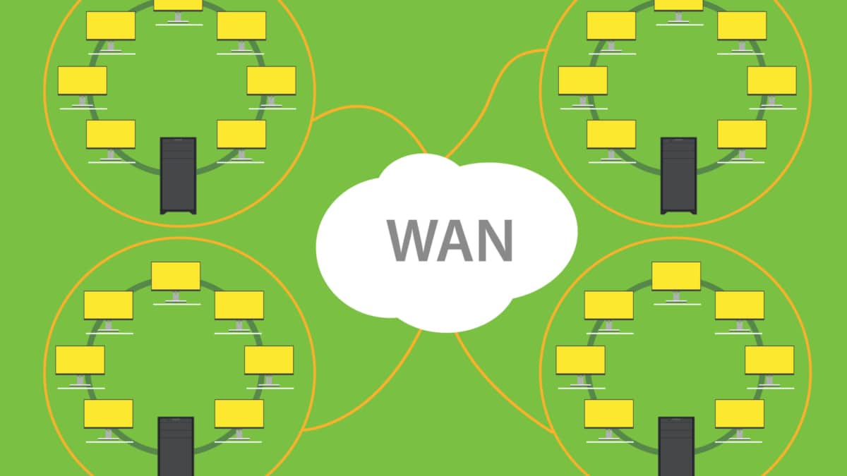
The hybrid cloud connects the public cloud provider to the private enterprise cloud. It consists of two or more distinct infrastructures in dispersed locations that remain unique. These unique entities are bound together logically via a network to enable data and application portability. LISP networking performs hybrid cloud and can overcome the negative drawback of stretched VLAN. How do you support intra-subnet traffic patterns among two dispersed cloud locations? Without a stretched VLAN spanning locations, instability may arise from broadcast storms and Layer 2 loops.
**End to End-to-end connectivity**
Enterprises want the ability to seamlessly insert their application right into the heart of the cloud provider without changing any parameters. Customers want to do this without changing the VM’s IP addresses and MAC addresses. This requires the VLAN to be stretched end-to-end. Unfortunately, IP routing cannot support VLAN extension, which puts pressure on the data center interconnect ( DCI ) link to enable extended VLANs. In reality, and from experience, this is not a good solution.
**LISP Architecture on Cisco Platforms**
There are various Cisco platforms that support LISP, but the platforms are mainly characterized by the operating system software they run. LISP is supported by Cisco’s IOS/IOS-XE, IOS-XR, and NX-OS operating systems. LISP offers several distinctive features and functions, including xTR/MS/MR, IGP Assist, and ESM/ASM Multi-hop. It is not true that all hardware supports all functions or features. Users need to verify that a platform supports key features before implementing it.
IOS-XR and NX-OS do not have distributed architectures, as does Cisco IOS/IOS-XE.RIB and Cisco Express Forwarding (CEF) provide the forwarding architecture for LISP on IOS/IOS-XE platforms using the LISP control process.
Before you proceed, you may find the following helpful:
- LISP Protocol
- LISP Hybrid Cloud Implementation
- Network Stretch
- LISP Control Plane
- Internet of Things Access Technologies
The LISP Network
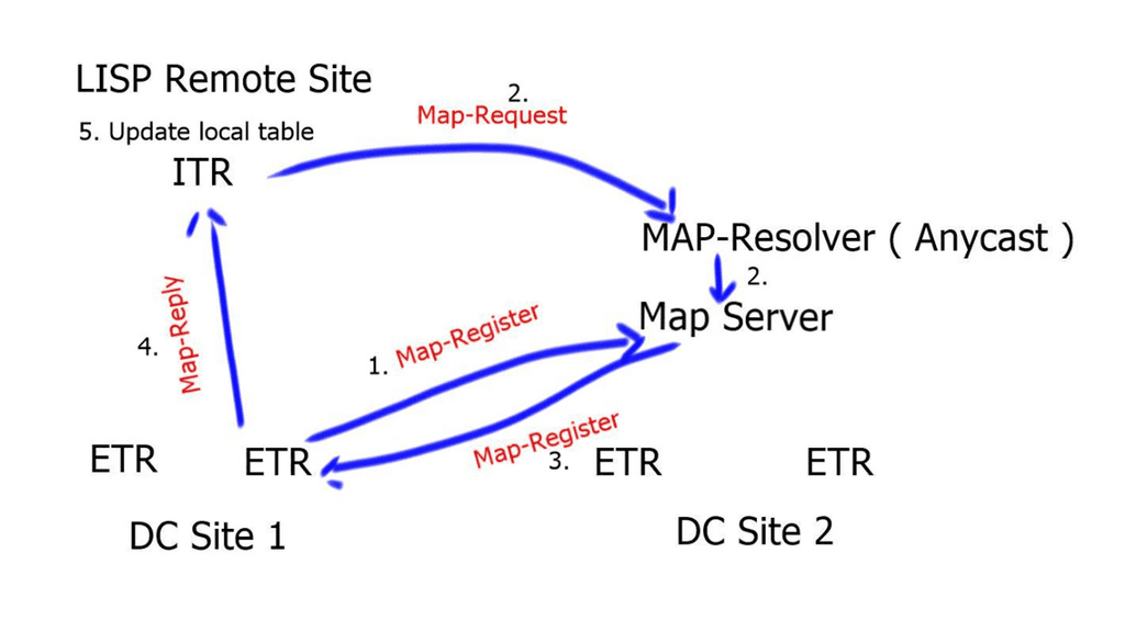
The LISP network comprises a mapping system with a global database of RLOC-EID mapping entries. The mapping system is the control plane of the LISP network decoupled from the data plane. The mapping system is address-family agnostic; the EID can be an IPv4 address mapped to an RLOC IPv6 address and vice versa. Or the EID may be a Virtual Extensible LAN (VXLAN) Layer 2 virtual network identifier (L2VNI) mapped to a VXLAN tunnel endpoint (VTEP) address working as an RLOC IP address.
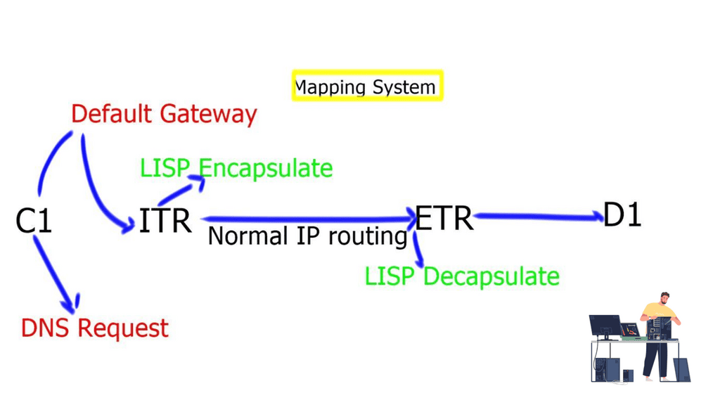
How Does LISP Networking Work? At its core, LISP networking introduces a new level of indirection between the device’s IP address and location. LISP relies on two key components: the xTR (eXternal Tunnel Router) and the mapping system. The xTR is responsible for encapsulating and forwarding traffic between different LISP sites, while the mapping system stores the mappings between the device’s identity and its current location.
**Benefits of LISP Networking**
Scalability: LISP provides a scalable solution for managing large networks by separating the device’s identity from its location. This allows for efficient routing and reduces the amount of routing table information that needs to be stored and exchanged.
Mobility: LISP networking offers seamless mobility support, enabling devices to change locations without disrupting ongoing communications. This is particularly beneficial in scenarios where mobile devices are constantly moving, such as IoT deployments or mobile networks.
Traffic Engineering: LISP allows network administrators to optimize traffic flow by manipulating the mappings between device IDs and locators. This provides greater control over network traffic and enables efficient load balancing and congestion management.
Security: LISP supports secure communications through the use of cryptographic techniques. It provides authentication and integrity verification mechanisms, ensuring the confidentiality and integrity of data transmitted over the network.
Use Cases for LISP Networking:
A – Data Centers: LISP can significantly simplify the management of large-scale data center networks by providing efficient traffic engineering and seamless mobility support for virtual machines.
B- Internet Service Providers (ISPs): LISP can help ISPs improve their network scalability and handle the increasing demand for IP addresses. It enables ISPs to optimize their routing tables and efficiently manage address space.
C- IoT Deployments: LISP’s mobility support and scalability make it an ideal choice for IoT deployments. It efficiently manages large devices and enables seamless connectivity as devices move across different networks.
LISP Networking and Stretched VLAN
Locator Identity Separation Protocol ( LISP ) can extend subnets without the VLAN. I am creating a LISP Hybrid Cloud. A subnet extension with LISP is far more appealing than a Layer 2 LAN extension. The LISP-enabled hybrid cloud solution allows Intra-subnet communication regardless of where the server is. This means you can have two servers in different locations, one in the public cloud and the other in the Enterprise domain; both servers can communicate as if they were on the same subnet.
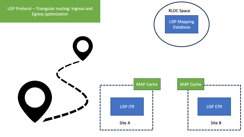
LISP acts as an overlay technology
LISP operates like an overlay technology; it encapsulates the source packet with UDP and a header consisting of the source and destination RLOC ( RLOC are used to map EIDS). The result is that you can address the servers in the cloud according to your addressing scheme. There is no need to match your addressing scheme to the cloud addressing scheme.
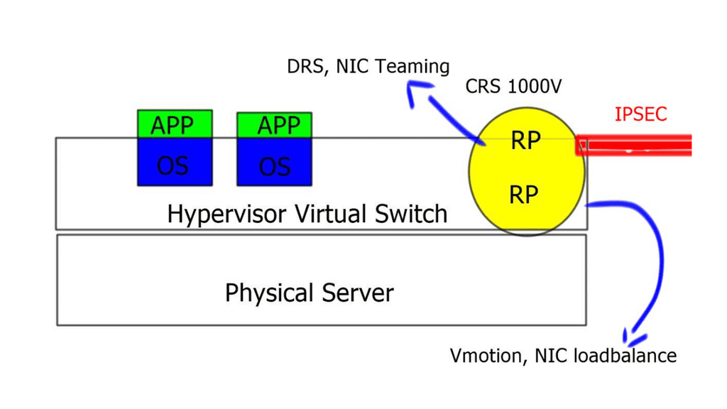
LISP on the Cloud Service Router ( CRS ) 1000V ( virtual router ) solution provides a Layer-3-based approach to a hybrid cloud. It allows you to stretch subnets from the enterprise to the public cloud without needing a Layer 2 LAN extension.
LISP networking deployment key points:
- LISP can be deployed with the CRS 1000V in the cloud and either a CRS 1000V or ASR 1000 in the enterprise domain.
- The enterprise CRS must have at least two interfaces. One interface is the L3 routed interface to the core. The second interface is a Layer 2 interface to support VLAN connectivity for the servers that require mobility.
- The enterprise CRS does not need to be the default gateway, and its interaction with the local infrastructure ( via the Layer 2 interface ) is based on Proxy-ARP. As a result, ARP packets must be allowed on the underlying networks.
- The Cloud CRS is also deployed with at least two interfaces. One interface is facing the Internet or MPLS network. The second interface faces the local infrastructure, either by VLANs or Virtual Extensible LAN ( VXLAN ).
- The CRS offers machine-level high availability and supports all the VMware high-availability features such as dynamic resource scheduling ( DRS ), vMotion, NIC load balancing, and teaming.
- LISP is a network-based solution and is independent of the hypervisor. You can have different hypervisors in the Enterprise and the public cloud. No changes to virtual servers or hosts. It’s completely transparent.
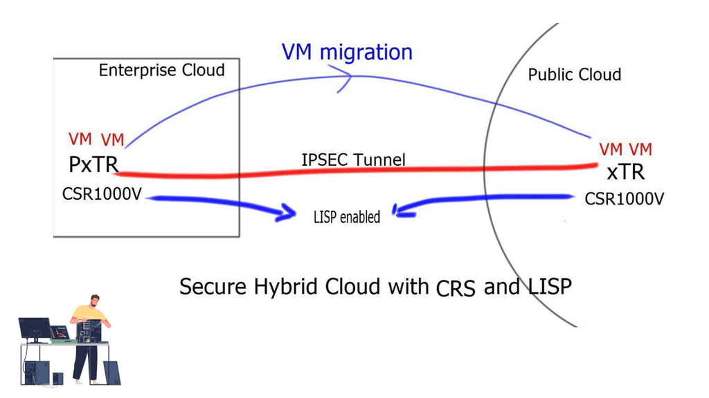
- The PxTR ( also used to forward to non-LISP sites ) is deployed in the enterprise cloud, and the xTR is deployed in the public cloud.
- The CRS1000V deployed in the public cloud is secured by an IPSEC tunnel. Therefore, the LISP tunnel should be encrypted using IPSEC tunnel mode. Tunnel mode is preferred to support NAT.
- Each CRS must have one unique outside IP address. This is used to form the IPSEC tunnel between the two endpoints.
- Dynamic or static Routing must be enabled over the IPSEC tunnel. This is to announce the RLOC IP address used by the LISP mapping system.
- The map-resolver ( MR ) and map server ( MS ) can be enabled on the xTR in the Enterprise or the xTR in the cloud.
- Traffic symmetry is still required when you have stateful devices in the path.
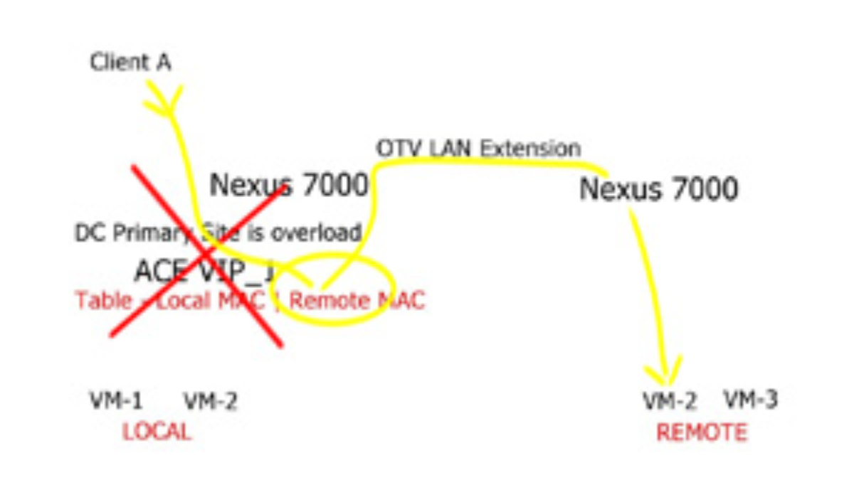
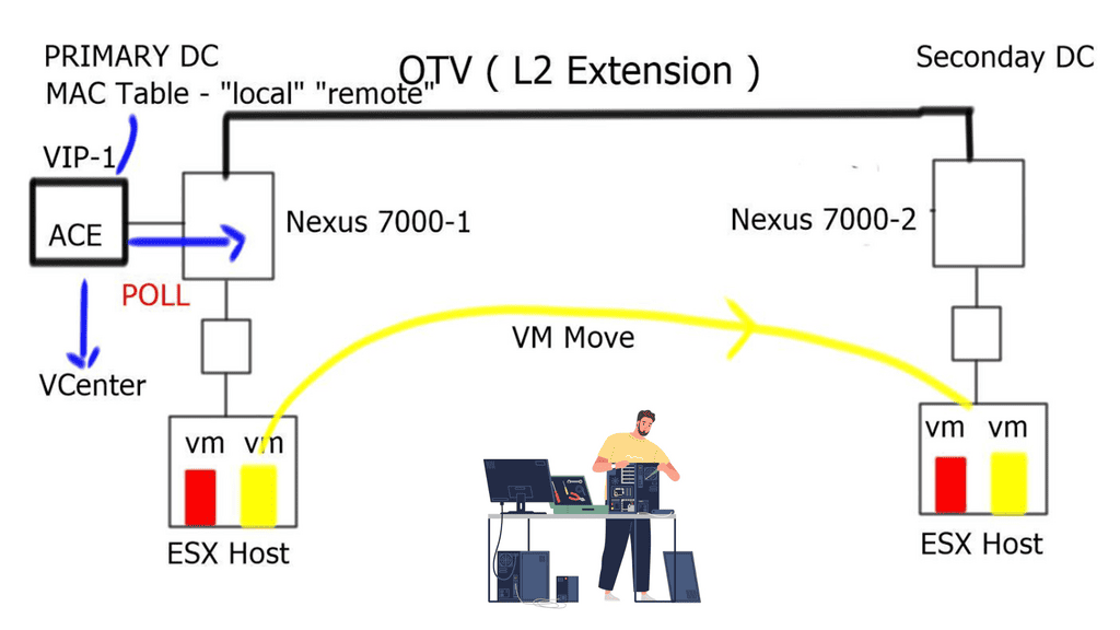
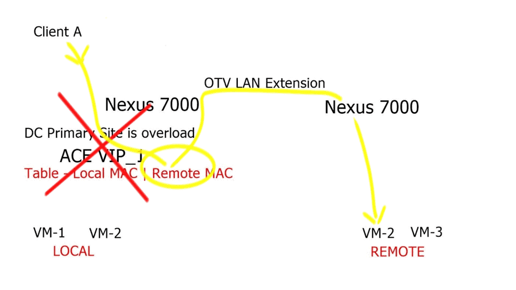
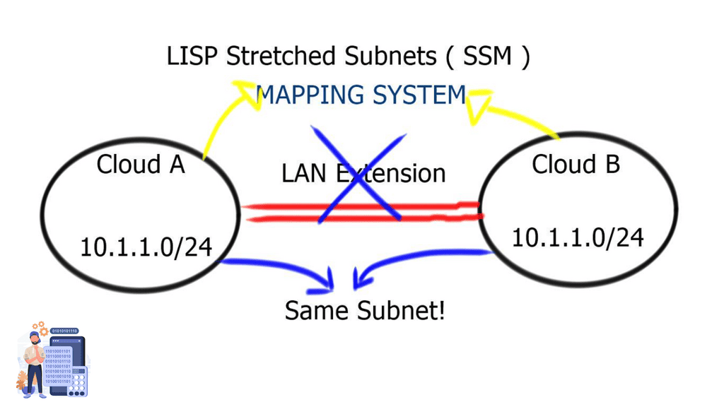
LISP stretched subnets
The two modes of LISP operation are the LISP “Across” subnet and the LISP “Extended” subnet mode. Neither of these modes is used with the LISP-enabled CRS hybrid cloud deployment scenario. The mode of operation utilized is called the LISP stretched subnet model ( SSM ). The same subnet is used on both sides of the network, and mobility is performed between these two segments on the same subnet. You may think that this is the same as LISP “Extended” subnet mode, but in this case, we are not using a LAN extension between sites. Instead, the extended mode requires a LAN extension such as OTV.
Closing Points on LISP Hybrid Cloud
LISP, or Locator/ID Separation Protocol, is a novel architecture that aims to improve the scalability and manageability of IP networks. By decoupling the location and identity of network devices, LISP enables more efficient routing and simplifies network management. This separation allows for seamless integration between different cloud environments, making it an ideal choice for hybrid cloud implementations. In a LISP-enabled network, endpoints have two addresses: an Endpoint Identifier (EID) that identifies the device and a Routing Locator (RLOC) that identifies its location in the network.
1. **Enhanced Scalability**: One of the key advantages of using LISP in a hybrid cloud setup is its ability to scale effortlessly. By separating identity and location, LISP reduces the complexity of routing tables, allowing networks to grow without the traditional limitations.
2. **Improved Security**: Security is a paramount concern for any cloud implementation. LISP provides improved security features by enabling network segmentation and facilitating the creation of secure communication tunnels between different cloud environments.
3. **Seamless Mobility**: LISP’s architecture supports seamless mobility, which is crucial for hybrid cloud environments where workloads may move between on-premises and cloud-based resources. This mobility ensures minimal disruption and consistent performance.
To successfully implement LISP in a hybrid cloud environment, organizations should follow a structured approach:
1. **Assessment and Planning**: Begin by assessing your current network infrastructure and identifying areas where LISP can bring the most value. Develop a detailed implementation plan that outlines the steps, resources, and timelines required.
2. **Deployment**: Deploy LISP-enabled routers and configure them to support both EIDs and RLOCs. Ensure that your network devices are compatible with the LISP protocol and that they are properly configured to handle LISP traffic.
3. **Testing and Optimization**: Conduct thorough testing to ensure that LISP is functioning as expected. Monitor network performance and make necessary adjustments to optimize routing and security.