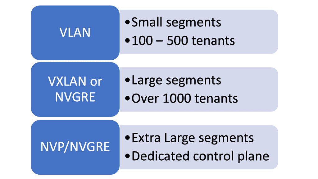
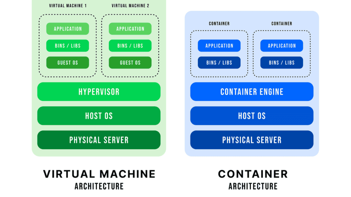
container based virtualization

Cisco Switch Virtualization Nexus 1000v

Cisco Switch Virtualization Nexus 1000v

Virtualization has become integral to modern data centers in today's digital landscape. With the increasing demand for agility, flexibility, and scalability, organizations are turning to virtual networking solutions to meet their evolving needs. One such solution is the Nexus 1000v, a virtual network switch offering comprehensive features and functionalities. In this blog post, we will delve into the world of the Nexus 1000v, exploring its key features, benefits, and use cases.

The Nexus 1000v is a distributed virtual switch that operates at the hypervisor level, providing advanced networking capabilities for virtual machines (VMs). It is designed to integrate seamlessly with VMware vSphere, offering enhanced network visibility, control, and security.

Cisco Switch Virtualization is a revolutionary concept that allows network administrators to create multiple virtual switches on a single physical switch. By abstracting the network functions from the hardware, it provides enhanced flexibility, scalability, and efficiency. With Cisco Switch Virtualization, businesses can maximize resource utilization and simplify network management.

At the forefront of Cisco's Switch Virtualization portfolio is the Nexus 1000v. This powerful platform brings the benefits of virtualization to the data center, enabling seamless integration between virtual and physical networks. By extending Cisco's renowned networking capabilities into the virtual environment, Nexus 1000v empowers organizations to achieve consistent policy enforcement, enhanced security, and simplified operations.

The Nexus 1000v boasts a wide range of features that make it a compelling choice for network administrators. From advanced network segmentation and traffic isolation to granular policy control and deep visibility, this platform has it all. By leveraging the power of Cisco's Virtual Network Services (VNS), organizations can optimize their network infrastructure, streamline operations, and deliver superior performance.

Deploying Cisco Switch Virtualization, specifically the Nexus 1000v, requires careful planning and consideration. Organizations must evaluate their network requirements, ensure compatibility with existing infrastructure, and adhere to best practices. From designing a scalable architecture to implementing proper security measures, attention to detail is crucial to achieve a successful deployment.

To truly understand the impact of Cisco Switch Virtualization, it's essential to explore real-world use cases and success stories. From large enterprises to service providers, organizations across various industries have leveraged the power of Nexus 1000v to transform their networks. This section will highlight a few compelling examples, showcasing the versatility and value that Cisco Switch Virtualization brings to the table.

Highlights: Cisco Switch Virtualization Nexus 1000v

Hypervisor and vSphere Introduction

An operating system can run multiple operating systems on a single hardware host using a hypervisor, also known as a virtual machine manager. Operating systems use the host’s processor, memory, and other resources. Hypervisors control the host processor, memory, and other resources and allocate what each operating system needs. Hypervisors run guest operating systems or virtual machines on top of them.

Designed specifically for integration with VMware vSphere environments, the Cisco Nexus 1000V Series Switch runs Cisco NX-OS software. Enterprise-class performance, scalability, and scalability are delivered by VMware vSphere 2.0 across multiple platforms. Within the VMware ESX hypervisor, the Nexus 1000V runs. With the Cisco Nexus 1000V Series, you can take advantage of Cisco VN-Link server virtualization technology

• Policy-based virtual machine (VM) connectivity

• Mobile VM security

• Network policy

Nondisruptive operational model for your server virtualization and networking teams

As with physical servers, virtual servers can be configured with the same network configuration, security policy, diagnostic tools, and operational models as physical servers. The Cisco Nexus 1000V Series is also compatible with VMware vSphere, vCenter, ESX, and ESXi.

A brief overview of the Nexus 1000V system

There are two primary components of the Cisco Nexus 1000V Series switch:

  • VEM (Virtual Ethernet Module): Executes inside hypervisors
  • VSM (External Virtual Supervisor Module): Manages VEMs

Nexus 1000v implements a generic concept of Cisco Distributed Virtual Switch (DVS). VMware ESX or ESXi executes the Cisco Nexus 1000V Virtual Ethernet Module (VEM). The VEM’s application programming interface (API) is VMware vNetwork Distributed Switch (vDS).

By integrating the API with VMware VMotion and Distributed Resource Scheduler (DRS), advanced networking capabilities can be provided to virtual machines. In the VEM, Layer 2 switching and advanced networking functions are performed based on configuration information from the VSM:

Nexus Switch Virtualization

**Virtual routing and forwarding**

Virtual routing and forwarding form the basis of this stack. Firstly, network virtualization comes with two primary methods: 1) One too many and 2) Many to one.  The “one too many” network virtualization method means you segment one physical network into multiple logical segments. Conversely, the “many to one” network virtualization method consolidates numerous physical devices into one logical entity. By definition, they seem to be opposites, but they fall under the same umbrella in network virtualization.

Before you proceed, you may find the following posts helpful:

  1. Container Based Virtualization
  2. Virtual Switch
  3. What is VXLAN
  4. Redundant Links
  5. WAN Virtualization
  6. What Is FabricPath

Network virtualization

Before we get stuck in Cisco virtualization, let us address some basics. For example, if you have multiple virtual endpoints share a physical network. Still, different virtual endpoints belong to various customers, and the communication between these endpoints also needs to be isolated. In other words, the network is a resource, too, and network virtualization is the technology that enables the sharing of a standard physical network infrastructure.

Virtualization uses software to simulate traditional hardware platforms and create virtual software-based systems. For example, virtualization allows specialists to construct a single virtual network or partition a physical network into multiple virtual networks.

Cisco Switch Virtualization: Logical segmentation: One too many

We have one-to-many network virtualization for the Cisco switch virtualization design; a single physical network is logically segmented into multiple virtual networks. For example, each virtual network could correspond to a user group or a specific security function.

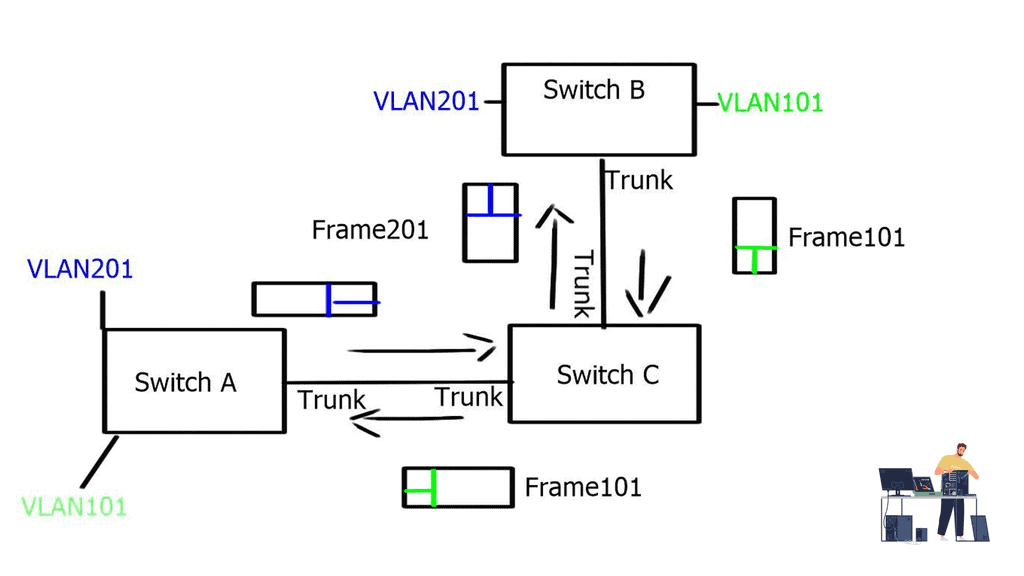
End-to-end path isolation requires the virtualization of networking devices and their interconnecting links. VLANs have been traditionally used, and hosts from one user group are mapped to a single VLAN. To extend the path across multiple switches at Layer 2, VLAN tagging (802.1Q) can carry VLAN information between switches. These VLAN trunks were created to transport multiple VLANs over a single Ethernet interface.

The diagram below displays two independent VLANs, VLAN201 and VLAN101. These VLANs can share one physical wire to provide L2 reachability between hosts connected to Switch B and Switch A via Switch C, but they remain separate entities.
Nexus1000v
Nexus1000v: The operation

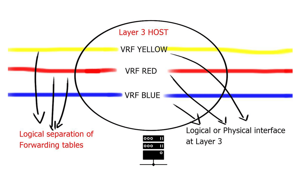
VLANs are sufficient for small Layer 2 segments. However, today’s networks will likely have a mix of Layer 2 and 3 routed networks. In this case, Layer 2 VLANs alone are insufficient because you must extend the Layer 2 isolation over a Layer 3 device. This can be achieved by using Virtual Routing and Forwarding ( VRF ), the next step in the Cisco switch virtualization. A virtual routing and forwarding instance logically carves a Layer 3 device into several isolated independent L3 devices. The virtual routing and forwarding configured locally cannot communicate directly.

The diagram below displays one physical Layer 3 router with three VRFs: VRF Yellow, VRF Red, and VRF Blue. These virtual routing and forwarding instances are completely separated; without explicit configuration, routes in one virtual routing and forwarding instance cannot be leaked to another.

Virtual Routing and Forwarding

virtual routing and forwarding

The virtualization of the interconnecting links depends on how the virtual routers are connected. If they are physically ( directly ) connected, you could use a technology known as VRF-lite to separate traffic and 802.1Q to label the data plane. This is known as hop-by-hop virtualization.

However, it’s possible to run into scalability issues when the number of devices grows. This design is typically used when you connect virtual routing and forwarding back to back, i.e., no more than two devices.

When the virtual routers are connected over multiple hops through an IP cloud, you can use generic routing encapsulation ( GRE ) or Multiprotocol Label Switching ( MPLS ) virtual private networks.

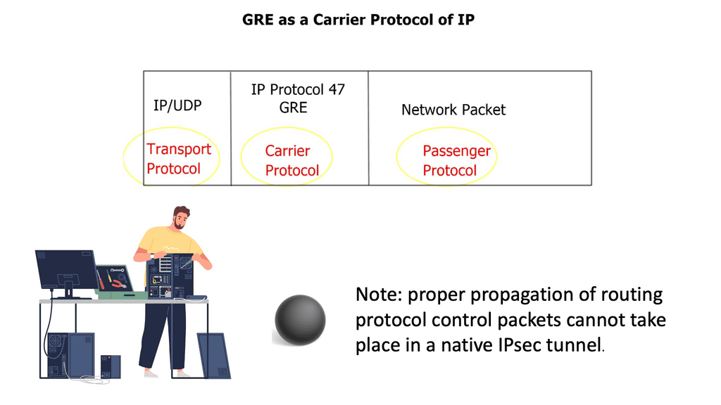
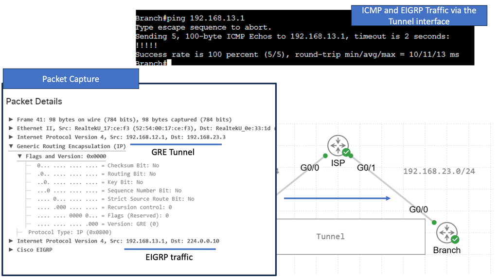
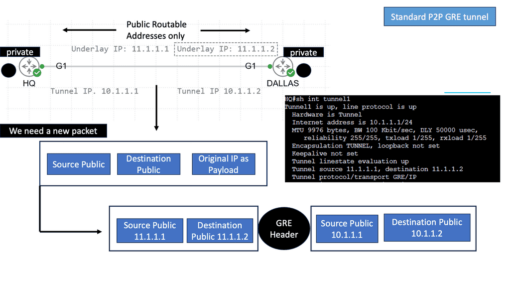
GRE is probably the simpler of the Layer 3 methods, and it can work over any IP core. GRE can encapsulate the contents and transport them over a network with the network unaware of the packet contents. Instead, the core will see the GRE header, virtualizing the network path.

Cisco Switch Virtualization: The additional overhead

When designing Cisco switch virtualization, you need to consider the additional overhead. There are a further 24 bytes overhead for the GRE header, so it may be the case that the forwarding router may break the datagram into two fragments, so the packet may not be larger than the outgoing interface MTU. To resolve the fragmentation issue, you can correctly configure MTU, MSS, and Path MTU parameters on the outgoing and intermediate routers.

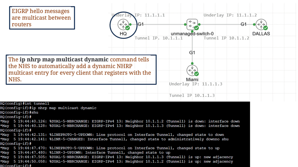
The GRE standard is typically static. You only need to configure tunnel endpoints, and the tunnel will be up as long as you can reach those endpoints. However, recent designs can establish a dynamic GRE tunnel.

GRE over IPsec

MPLS/VPN, on the other hand, is a different beast. It requires signaling to distribute labels and build an end-to-end Label Switched Path ( LSP ). The label distribution can be done with BGP+label, LDP, and RSVP. Unlike GRE tunnels, MPLS VPNs do not have to manage multiple point-to-point tunnels to provide a full mesh of connectivity. Instead, they are used for connectivity, and packets’ labels provide traffic separation.

Cisco switch virtualization: Many to one

Many-to-one network consolidation refers to grouping two or more physical devices into one. Examples of this Cisco switch virtualization technology include a Virtual Switching System ( VSS ), Stackable switches, and Nexus VPC. Combining many physicals into one logical entity allows STP to view the logical group as one, allowing all ports to be active. By default, STP will block the redundant path.

Software-defined networking takes this concept further; it completely abstracts the entire network into a single virtual switch. The control and data planes are on the same device on traditional routers, yet they are decoupled with SDN. The control plan is now on a policy-driven controller, and the data plane is local on the OpenFlow-enabled switch.

Network Virtualization

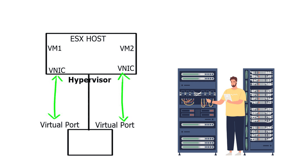
Server and network virtualization presented the challenge of multiple VMs sharing a single network physical port, such as a network interface controller ( NIC ). The question then arises: how do I link multiple VMs to the same uplink? How do I provide path separation? Today’s networks need to virtualize the physical port and allow the configuration of policies per port.

Nexus 1000

NIC-per-VM design

One way to do this is to have a NIC-per-VM design where each VM is assigned a single physical NIC, and the NIC is not shared with any other VM. The hypervisor, aka virtualization layer, would be bypassed, and the VM would access the I/O device directly. This is known as VMDirectPath.

This direct path or pass-through can improve performance for hosts that utilize high-speed I/O devices, such as 10 Gigabit Ethernet. However, the lack of flexibility and the ability to move VMs offset higher performance benefits.  

Virtual-NIC-per-VM in Cisco UCS (Adapter FEX)

Another way to do this is to create multiple logical NICs on the same physical NIC, such as Virtual-NIC-per-VM in Cisco UCS (Adapter FEX). These logical NICs are assigned directly to VMs, and traffic gets marked with a vNIC-specific tag on the hardware (VN-Tag/802.1ah).

The actual VN-Tag tagging is implemented in the server NICs so that you can clone the physical NIC in the server to multiple virtual NICs. This technology provides faster switching and enables you to apply a rich set of management features to local and remote traffic.

Software Virtual Switch

The third option is to implement a virtual software switch in the hypervisor. For example, VMware introduced virtual switching compatibility with its vSphere ( ESXi ) hypervisor, called vSphere Distributed Switch ( VDS ). Initially, they introduced a local L2 software switch, which was soon phased out due to a lack of distributed architecture.

Data physically moves between the servers through the external network, but the control plane abstracts this movement to look like one large distributed switch spanning multiple servers. This approach has a single management and configuration point, similar to stackable switches – one control plane with many physical data forwarding paths.

The data does not move through a parent partition but logically connects directly to the network interface through local vNICs associated with each VM.

Network virtualization and Nexus 1000v ( Nexus 1000 )

The VDS introduced by VMware lacked any good networking features, which led Cisco to introduce the Nexus 1000V software-based switch. The Nexus 1000v is a multi-cloud, multi-hypervisor, and multi-services distributed virtual switch. Its function is to enable communication between VMs.
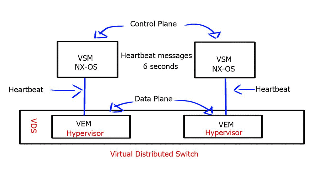
Nexus1000v
Nexus1000v: Virtual Distributed Switch.

**Nexus 1000 components: VEM and VSM**

The Nexus 1000v has two essential components:

  1. The Virtual Supervisor Module ( VSM )
  2. The Virtual Ethernet Module ( VEM ).

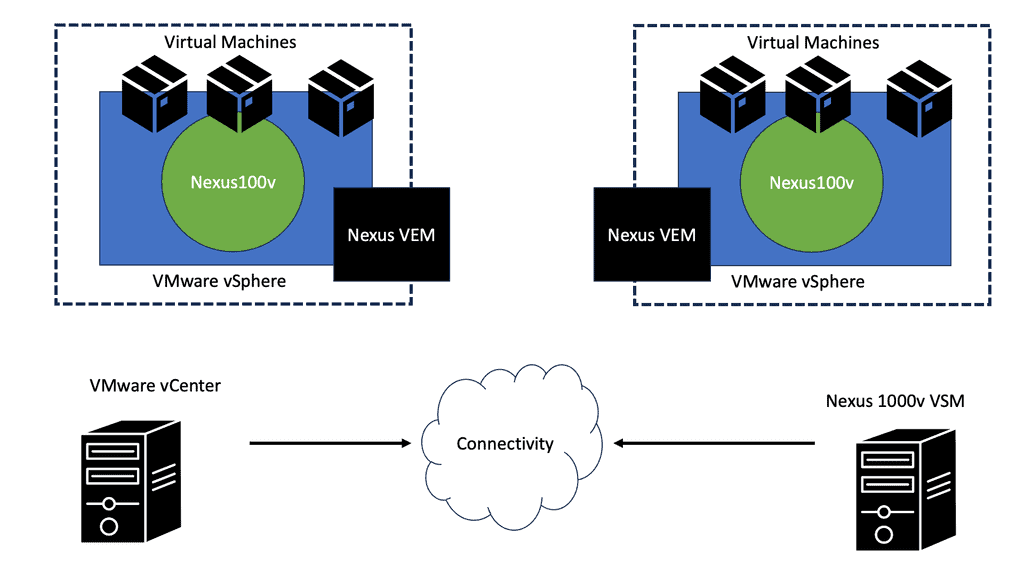
Compared to a physical switch, the VSM could be viewed as the supervisor, setting up the control plane functions for the data plane to forward efficiently, and the VEM as the physical line cards that do all the packet forwarding. The VEM is the software component that runs within the hypervisor kernel. It handles all VM traffic, including inter-VM frames and Ethernet traffic between a VM and external resources.

The VSM runs its NX-OS code and controls the control and management planes, which integrate into a cloud manager, such as a VMware vCenter. You can have two VSMs for redundancy. Both modules remain constantly synchronized with unicast VSM-to-VSM heartbeats to provide stateful failover in the event of an active VSM failure.

The two available communication options for VSM to VEM are:

  1. Layer 2 control mode: The VSM control interface shares the same VLAN with the VEM.
  2. Layer 3 control mode: The VEM and the VSM are in different IP subnets.

The VSM also uses heartbeat messages to detect a loss of connectivity between it and the VEM. However, the VEM does not depend on connectivity to the VSM to perform its data plane functions and will continue forwarding packets if the VSM fails.

With Layer 3 control mode, the heartbeat messages are encapsulated in a GRE envelope.

Nexus 1000 and VSM best practices

  • L2 control is recommended for new installations.
  • Use MAC pinning instead of LACP.
  • Packet, Control, and Management in the same VLAN.
  • Do not use VLAN 1 for Control and Packet.
  • Use 2 x VSM for redundancy. 

The max latency between VSM and VEM is ten milliseconds. Therefore, a VSM can be placed outside the data center if you have a high-quality DCI link, and the VEM can still be controlled.

Nexus 1000v InterCloud – Cisco switch virtualization

A vital element of the Nexus 1000 is its use case for hybrid cloud deployments and its ability to place workloads in private and public environments via a single pane of glass. In addition, the Nexus 1000v interCloud addresses the main challenges with hybrid cloud deployments, such as security concerns and control/visibility challenges within the public cloud.

The Nexus 1000 interCloud works with Cisco Prime Service Controller to create a secure L2 extension between the private data center and the public cloud.

This L2 extension is based on Datagram Transport Layer Security ( DTLS ) protocol and allows you to securely transfer VMs and Network services over a public IP backbone. DTLS derives the SSL protocol and provides communications privacy for datagram protocols, so all data in motion is cryptographically isolated and encrypted.
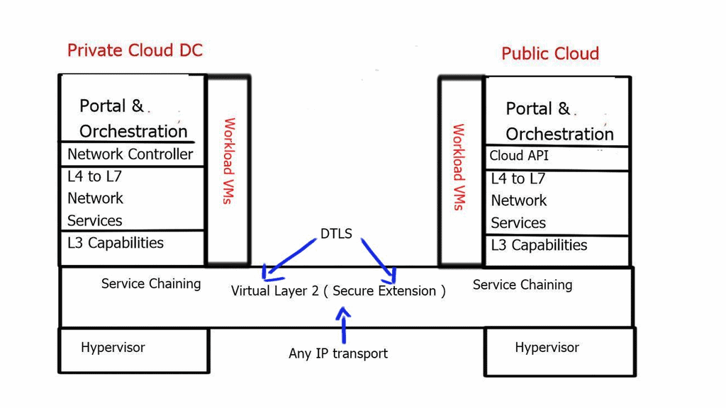
Nexus 1000
Nexus 1000 and Hybrid Cloud.


Nexus 1000v Hybrid Cloud Components 

Cisco Prime Network Service Controller for InterCloud **A VM that provides a single pane of glass to manage all functions of the inter clouds
InterCloud VSMManage port profiles for VMs in the InterCloud infrastructure
InterCloud ExtenderProvides secure connectivity to the InterCloud Switch in the provider cloud. Install in the private data center.
InterCloud SwitchVirtual Machine in the provider data center has secure connectivity to the InterCloud Extender in the enterprise cloud and secure connectivity to the Virtual Machines in the provider cloud.
Cloud Virtual MachinesVMs in the public cloud running workloads.

Prerequisites

Port 80HTTP access from PNSC for AWS calls and communicating with InterCloud VMs in the provider cloud
Port 443HTTPS access from PNSC for AWS calls and communicating with InterCloud VMs in the provider cloud
Port 22SSH from PNSC to InterCloud VMs in the provider cloud
UDP 6644DTLS data tunnel
TCP 6644DTLS control tunnel

VXLAN – Virtual Extensible LAN

The requirement for applications on demand has led to an increased number of required VLANs for cloud providers. The standard 12-bit identifier, which provided 4000 VLANs, proved to be a limiting factor in multi-tier, multi-tenant environments, and engineers started to run out of isolation options.

This has introduced a 24-bit VXLAN identifier, offering 16 million logical networks. Now, we can cross Layer 3 boundaries. The MAC in UDP encapsulation uses switch hashing to analyze UDP packets and efficiently distribute all packets in a port channel.
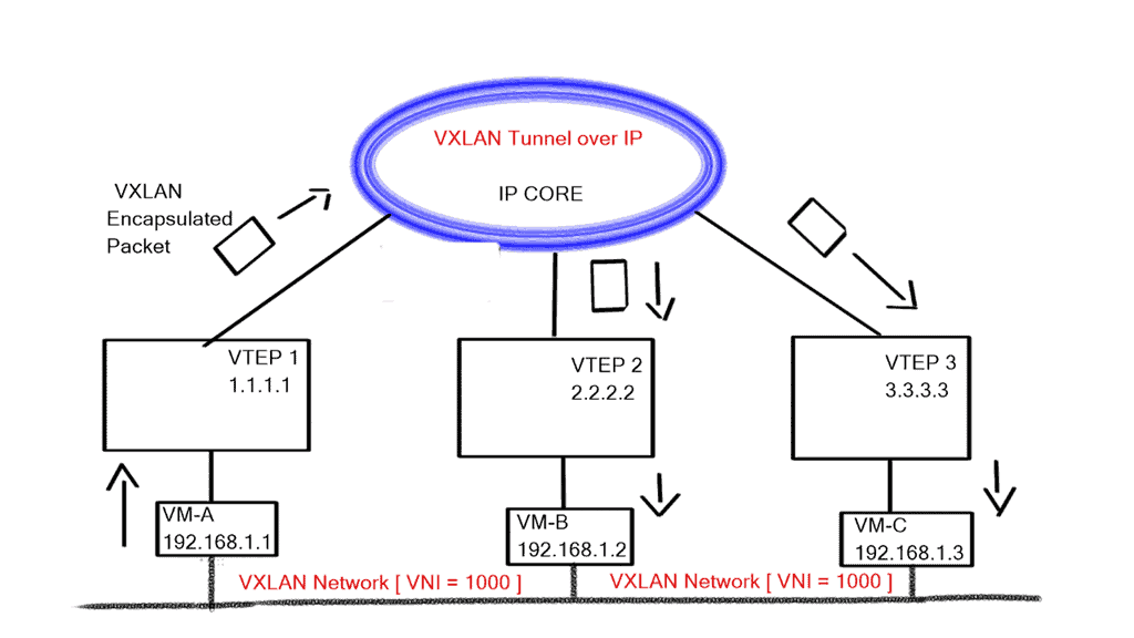
nexus 1000
VXLAN operations

VXLAN works like a layer 2 bridge ( Flood and Learn ); the VEM learn does all the heavy lifting, learns all the VM source MAC and Host VXLAN IPs, and encapsulates the traffic according to the port profile to which the VM belongs. Broadcast, Multicast, and unknown unicast traffic are sent as Multicast.

At the same time, unicast traffic is encapsulated and shipped directly to the destination host’s VXLAN IP, aka destination VEM. Enhanced VXLAN offers VXLAN MAC distribution and ARP termination, making it more optional. 

VXLAN Mode Packet Functions

PacketVXLAN(multicast mode)Enhanced VXLAN(unicast mode)Enhanced VXLANMAC DistributionEnhanced VXLANARP Termination
Broadcast /MulticastMulticast EncapsulationReplication plus Unicast EncapReplication plus Unicast EncapReplication plus Unicast Encap
Unknown UnicastMulticast EncapsulationReplication plus Unicast EncapDropDrop
Known UnicastUnicast EncapsulationUnicast EncapUnicast EncapUnicast Encap
ARPMulticast EncapsulationReplication plus Unicast EncapReplication plus Unicast EncapVEM ARP Reply

vPath – Service chaining

Intelligent Policy-based traffic steering through multiple network services.

vPath allows you to intelligently traffic steer VM traffic to virtualized devices. It intercepts and redirects the initial traffic to the service node. Once the service node performs its policy function, the result is cached, and the local virtual switch treats the subsequent packets accordingly. In addition, it enables you to tie services together to push the VM through each service as required. Previously, if you wanted to tie services together in a data center, you needed to stitch the VLANs together, which was limited by design and scale.
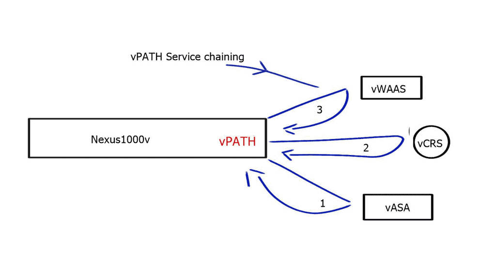
Cisco virtualization
Nexus and service chaining

vPath 3.0 is now submitted to the IETF for standardization, allowing service chaining with vPath and non-vpath network services. It enables you to use vpath service chaining between multiple physical devices and supporting multiple hypervisors.

License Options 

Nexus 1000 Essential EditionNexus 1000 Advanced Edition
Full Layer-2 Feature SetAll Features of Essential Edition
Security, QoS PoliciesVSG firewall
VXLAN virtual overlaysVXLAN Gateway
vPath enabled Virtual ServicesTrustSec SGA
Full monitoring and management capabilitiesA platform for other Cisco DC Extensions in the Future
Free$695 per CPU MSRP

Nexus 1000 features and benefits

SwitchingL2 Switching, 802.1Q Tagging, VLAN, Rate Limiting (TX), VXLAN
IGMP Snooping, QoS Marking (COS & DSCP), Class-based WFQ
SecurityPolicy Mobility, Private VLANs w/ local PVLAN Enforcement
Access Control Lists, Port Security, Cisco TrustSec Support
Dynamic ARP inspection, IP Source Guard, DHCP Snooping
Network ServicesVirtual Services Datapath (vPath) support for traffic steering & fast-path off-load[leveraged by Virtual Security Gateway (VSG), vWAAS, ASA1000V]
ProvisioningPort Profiles, Integration with vC, vCD, SCVMM*, BMC CLM
Optimized NIC Teaming with Virtual Port Channel – Host Mode
VisibilityVM Migration Tracking, VC Plugin, NetFlow v.9 w/ NDE, CDP v.2
VM-Level Interface Statistics, vTrackerSPAN & ERSPAN (policy-based)
ManagementVirtual Centre VM Provisioning, vCenter Plugin, Cisco LMS, DCNM
Cisco CLI, Radius, TACACs, Syslog, SNMP (v.1, 2, 3)
Hitless upgrade, SW Installer

Advantages and disadvantages of the Nexus 1000

AdvantagesDisadvantages
The Standard edition is FREE; you can upgrade to an enhanced version when needed.VEM and VSM internal communication is very sensitive to latency. Due to their chatty nature, they may not be good for inter-DC deployments.
Easy and Quick to deployVSM – VEM, VSM (active) – VSM (standby) heartbeat time of 6 seconds makes it sensitive to network failures and congestion.
It offers you many rich network features unavailable on other distributed software switches.VEM over-dependency on VSM reduces resiliency.
Hypervisor agnosticVSM is required for vSphere HA, FT, and VMotion to work.
Hybrid Cloud functionality 

**Closing Points on Cisco Nexus 1000v**

Virtual Ethernet Module (VEM):

The Nexus 1000v employs the Virtual Ethernet Module (VEM), which runs as a module inside the hypervisor. This allows for efficient and direct communication between VMs, bypassing the traditional reliance on the hypervisor networking stack.

Virtual Supervisor Module (VSM):

The Virtual Supervisor Module (VSM) serves as the control plane for the Nexus 1000v, providing centralized management and configuration. It enables network administrators to define policies, manage virtual ports, and monitor network traffic.

Policy-Based Virtual Network Management:

With the Nexus 1000v, administrators can define policies to manage virtual networks. These policies ensure consistent network configurations across multiple hosts, simplifying network management and reducing the risk of misconfigurations.

Advanced Security and Monitoring Capabilities:

The Nexus 1000v offers granular security controls, including access control lists (ACLs), port security, and dynamic host configuration protocol (DHCP) snooping. Additionally, it provides comprehensive visibility into network traffic, enabling administrators to monitor and troubleshoot network issues effectively.

Benefits of the Nexus 1000v:

Enhanced Network Performance:

By offloading network processing to the VEM, the Nexus 1000v minimizes the impact on the hypervisor, resulting in improved network performance and reduced latency.

Increased Scalability:

The distributed architecture of the Nexus 1000v allows for seamless scalability, ensuring that organizations can meet the growing demands of their virtualized environments.

Simplified Network Management:

With its policy-based approach, the Nexus 1000v simplifies network management tasks, enabling administrators to provision and manage virtual networks more efficiently.

Use Cases:

Data Centers:

The Nexus 1000v is particularly beneficial in data center environments where virtualization is prevalent. It provides a robust and scalable networking solution, ensuring optimal performance and security for virtualized workloads.

Cloud Service Providers:

Cloud service providers can leverage the Nexus 1000v to enhance their network virtualization capabilities, offering customers more flexibility and control over their virtual networks.

The Nexus 1000v is a powerful virtual network switch that provides advanced networking capabilities for virtualized environments. Its rich features, policy-based management approach, and seamless integration with VMware vSphere allow organizations to achieve enhanced network performance, scalability, and management efficiency. As virtualization continues to shape the future of data centers, the Nexus 1000v remains a valuable tool for optimizing virtual network infrastructures.

Summary: Cisco Switch Virtualization Nexus 1000v

Welcome to our blog post, where we dive into the world of Cisco Switch Virtualization, explicitly focusing on the Nexus 1000v. In this article, we will unravel the complexities surrounding switch virtualization, explore the key features of the Nexus 1000v, and understand its significance in modern networking environments.

Understanding Switch Virtualization

Switch virtualization is a technique that allows for creating multiple virtual switches on a single physical switch, enabling greater flexibility and efficiency in network management. Organizations can consolidate their infrastructure, reduce costs, and streamline network operations by virtualizing switches.

Introducing the Nexus 1000v

The Cisco Nexus 1000v is a powerful switch virtualization solution that extends the functionality of VMware environments. Unlike traditional virtual switches, it provides a more comprehensive set of features and advanced network control. It seamlessly integrates with VMware vSphere, offering enhanced visibility, security, and policy management.

Key Features of the Nexus 1000v

– Distributed Virtual Switch: The Nexus 1000v operates as a distributed virtual switch, distributing network intelligence across all hosts in the virtualized environment. This ensures consistent policies, simplified troubleshooting, and improved performance.

– Virtual Port Profiles: With virtual port profiles, administrators can define consistent network policies for virtual machines, irrespective of their physical location. This simplifies network provisioning and reduces the chances of misconfigurations.

– Network Analysis Module (NAM): The Nexus 1000v incorporates NAM, a robust monitoring and analysis tool that provides deep visibility into virtual network traffic. This enables administrators to identify and resolve network issues, ensuring optimal performance quickly.

Deployment Considerations

When planning to deploy the Nexus 1000v, it is essential to consider factors such as network architecture, compatibility with existing infrastructure, and scalability requirements. It is advisable to consult with Cisco experts or certified partners to ensure a smooth and successful implementation.

Conclusion:

In conclusion, the Cisco Nexus 1000v is a game-changer in switch virtualization. Its advanced features, seamless integration with VMware environments, and extensive network control make it an ideal choice for organizations seeking to optimize their network infrastructure. By understanding the fundamentals of switch virtualization and exploring Nexus 1000v’s capabilities, network administrators can unlock a world of possibilities in network management and performance.

What is VXLAN

What is VXLAN

What is VXLAN

In the rapidly evolving networking world, virtualization has become critical for businesses seeking to optimize their IT infrastructure. One key technology that has emerged is VXLAN (Virtual Extensible LAN), which enables the creation of virtual networks independent of physical network infrastructure. In this blog post, we will delve into the concept of VXLAN, its benefits, and its role in network virtualization.

VXLAN is an encapsulation protocol designed to extend Layer 2 (Ethernet) networks over Layer 3 (IP) networks. It provides a scalable and flexible solution for creating virtualized networks, enabling seamless communication between virtual machines (VMs) and physical servers across different data centers or geographic regions.

VXLAN is a technology that creates virtual networks within an existing physical network. A Layer 2 overlay network runs on top of the current Layer 2 network. VXLAN utilizes UDP as the transport protocol, providing a secure, efficient, and reliable way to create a virtual network.

VXLAN encapsulates the original Layer 2 Ethernet frames within UDP packets, using a 24-bit VXLAN Network Identifier (VNI) to distinguish between different virtual networks. The encapsulated packets are then transmitted over the underlying IP network, enabling the creation of virtualized Layer 2 networks across Layer 3 boundaries.

Scalability: VXLAN solves the limitations of traditional VLANs by providing a much larger network identifier space, accommodating up to 16 million virtual networks. This scalability allows for the efficient isolation and segmentation of network traffic in highly virtualized environments.

VXLAN enables the decoupling of virtual and physical networks, providing the flexibility to move virtual machines across different physical hosts or even data centers without the need for reconfiguration. This flexibility greatly simplifies workload mobility and enhances overall network agility.

Multitenancy: With VXLAN, multiple tenants can securely share the same physical infrastructure while maintaining isolation between their virtual networks. This is achieved by assigning unique VNIs to each tenant, ensuring their traffic remains separate and secure.

Underlay Network: VXLAN relies on an IP underlay network, which must provide sufficient bandwidth, low latency, and optimal routing. Careful planning and design of the underlay network are crucial to ensure optimal VXLAN performance.
Network Virtualization Gateway: To enable communication between VXLAN-based virtual networks and traditional VLAN-based networks, a network virtualization gateway, such as a VXLAN Gateway or an overlay-to-underlay gateway, is required. These gateways bridge the gap between virtual and physical networks, facilitating seamless connectivity.

Highlights: What is VXLAN

Understanding VXLAN Basics

It is essential to grasp VXLAN’s fundamental concepts to comprehend it. VXLAN enables the creation of virtualized Layer 2 networks over an existing Layer 3 infrastructure. It uses encapsulation techniques to extend Layer 2 segments over long distances, enabling flexible deployment of virtual machines across physical hosts and data centers.

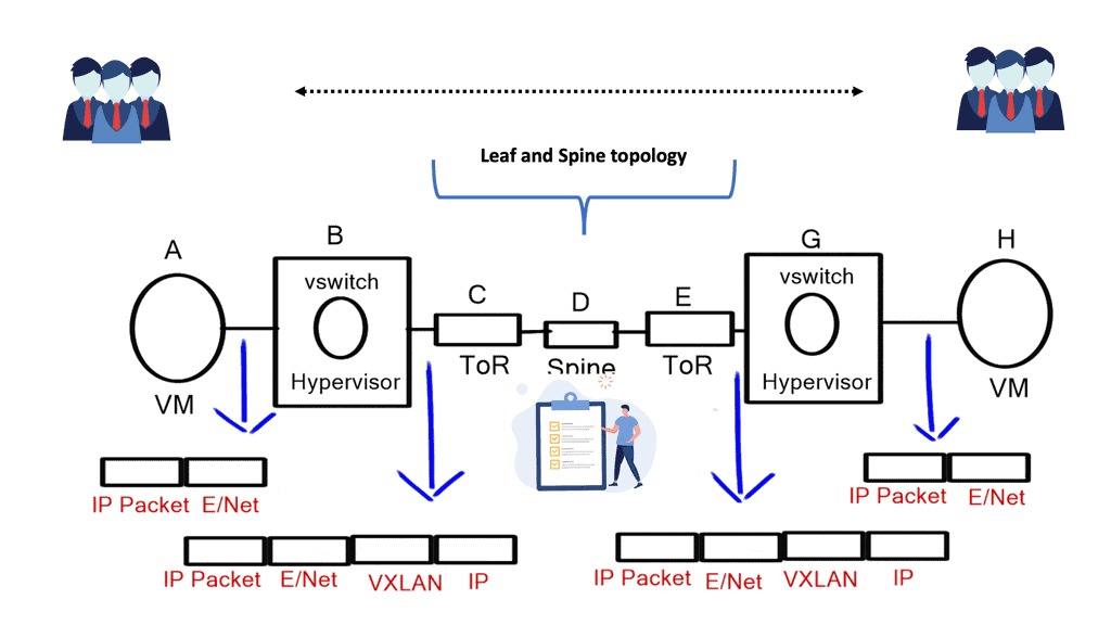
VXLAN Encapsulation: One of the key components of VXLAN is encapsulation. When a virtual machine sends data across the network, VXLAN encapsulates the original Ethernet frame within a new UDP/IP packet. This encapsulated packet is then transmitted over the underlying Layer 3 network, allowing for seamless communication between virtual machines regardless of their physical location.

VXLAN Tunneling: VXLAN employs tunneling to transport the encapsulated packets between VXLAN-enabled devices. These devices, known as VXLAN Tunnel Endpoints (VTEPs), establish tunnels to carry VXLAN traffic. By leveraging tunneling protocols like Generic Routing Encapsulation (GRE) or Virtual Extensible LAN (VXLAN-GPE), VTEPs ensure the delivery of encapsulated packets across the network.

**Benefits of VXLAN**

VXLAN brings numerous benefits to modern network architectures. It enables network virtualization and multi-tenancy, allowing for the efficient and secure isolation of network segments. VXLAN also provides scalability, as it can support a significantly higher number of virtual networks than traditional VLAN-based networks. Additionally, VXLAN facilitates workload mobility and disaster recovery, making it an ideal choice for cloud environments.

**Implementing VXLAN**

VXLAN Implementation Considerations: While VXLAN offers immense advantages, there are a few considerations to consider when implementing it. VXLAN requires network devices that support the technology, including VTEPs and VXLAN-aware switches. It is also crucial to properly configure and manage the VXLAN overlay network to ensure optimal performance and security.

Data centers evolution

In recent years, data centers have seen a significant evolution. This evolution has brought popular technologies such as virtualization, cloud computing (private, public, and hybrid), and software-defined networking (SDN). Mobile-first and cloud-native data centers must scale, be agile, secure, consolidate, and integrate with compute/storage orchestrators. As well as visibility, automation, ease of management, operability, troubleshooting, and advanced analytics, today’s data center solutions are expected to include many other features.

A more service-centric approach is replacing device-by-device management. Most requests for proposals (RFPs) specify open application programming interfaces (APIs) and standards-based protocols to prevent vendor lock-in. A Cisco Virtual Extensible LAN (VXLAN)-based fabric using Nexus switches2 and NX-OS controllers form Cisco Virtual Extensible LAN (VXLAN).

what is spine and leaf architecture
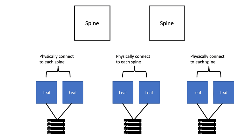
Diagram: What is spine and leaf architecture. 2-Tier Spine Leaf Design

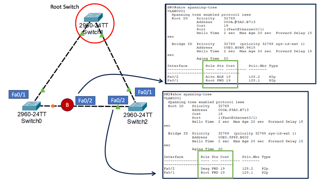
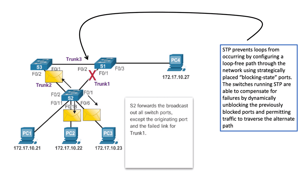
Issues with STP

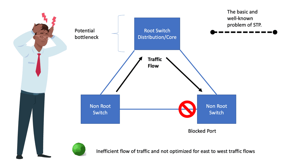
When a switch receives redundant paths, the spanning tree protocol must designate one of those paths as blocked to prevent loops. While this mechanism is necessary, it can lead to suboptimal network performance. Blocked ports limit bandwidth utilization, which can be particularly problematic in environments with heavy data traffic.
One significant concern with the spanning tree protocol is its slow convergence time. When a network topology changes, the protocol takes time to recompute the spanning tree and reestablish connectivity. During this convergence period, network downtime can occur, disrupting critical operations and causing frustration for users.

stp port states

What is VXLAN?

The Internet Engineering Task Force (IETF) developed VXLAN, or Virtual eXtensible Local-Area Network, as a network virtualization technology standard. Multi-tenant networks allow multiple organizations to share a physical network without accessing each other’s traffic.

The VXLAN can be compared to individual apartment apartments: each apartment is a separate, private dwelling within a shared physical structure, just as each VXLAN is a discrete, private network segment within a shared physical infrastructure.

With VXLANs, physical networks can be segmented into 16 million logical networks. To encapsulate Layer 2 Ethernet frames, User Datagram Protocol (UDP) packets with a VXLAN header are used. Combining VXLAN with Ethernet virtual private networks (EVPNs), which transport Ethernet traffic over WAN protocols, allows Layer 2 networks to be extended across Layer 3 IP or MPLS networks.

**Benefits of VXLAN:**

– Scalability: VXLAN allows creating up to 16 million logical networks, providing the scalability required for large-scale virtualized environments.

– Network Segmentation: By leveraging VXLAN, organizations can segment their networks into virtual segments, enhancing security and isolating traffic between applications or user groups.

– Flexibility and Mobility: VXLAN enables the movement of VMs across physical servers and data centers without the need to reconfigure network settings. This flexibility is crucial for workload mobility in dynamic environments.

– Interoperability: VXLAN is an industry-standard protocol supported by various networking vendors, ensuring compatibility across different network devices and platforms.

**Use Cases for VXLAN**

– Data Center Interconnect (DCI): VXLAN allows organizations to interconnect multiple data centers, enabling seamless workload migration, disaster recovery, and workload balancing across different locations.

– Multi-Tenant Environments: VXLAN enables service providers to offer virtualized network services to multiple tenants securely and isolatedly. This is particularly useful in cloud computing environments.

– Network Virtualization: VXLAN plays a crucial role in network virtualization, allowing organizations to create virtual networks independent of the underlying physical infrastructure. This enables greater flexibility and agility in managing network resources.

**VXLAN vs. GRE**

VXLAN, an overlay network technology, is designed to address the limitations of traditional VLANs. It enables the creation of virtual networks over an existing Layer 3 infrastructure, allowing for more flexible and scalable network deployments. VXLAN operates by encapsulating Layer 2 Ethernet frames within UDP packets, extending Layer 2 domains across Layer 3 boundaries.

GRE, on the other hand, is a simple IP packet encapsulation protocol. It provides a mechanism for encapsulating arbitrary protocols over an IP network and is widely used for creating point-to-point tunnels. GRE encapsulates the payload packets within IP packets, making it a versatile option for connecting remote networks securely.

GRE without IPsec

Point-to-point GRE networks serve as a foundational element in modern networking. They allow for encapsulation and efficient transmission of various protocols over an IP network. Point-to-point GRE networks enable seamless communication and data transfer by establishing a direct virtual link between two endpoints.

Understanding mGRE

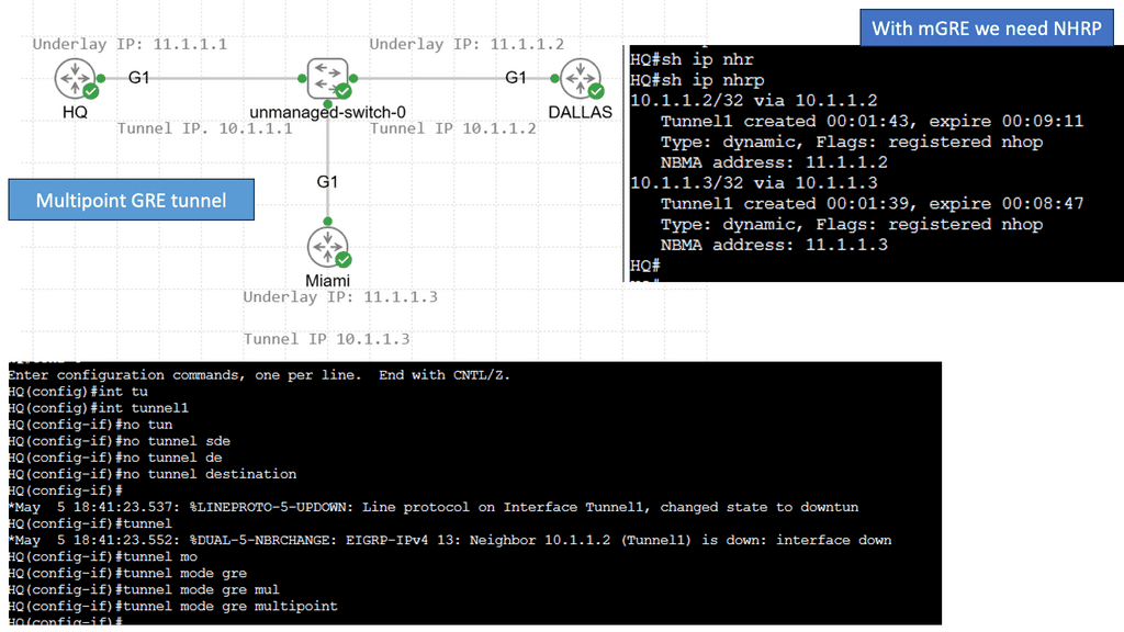
mGRE serves as the foundation for building DMVPN networks. It allows multiple sites to communicate with each other over a shared public network infrastructure while maintaining security and scalability. By utilizing a single mGRE tunnel interface on a central hub router, multiple spoke routers can dynamically establish and tear down tunnels, enabling seamless communication across the network.

The utilization of mGRE within DMVPN offers several key advantages. First, it simplifies network configuration by eliminating the need for point-to-point tunnels between each spoke router. Second, mGRE provides scalability, allowing for the dynamic addition or removal of spoke routers without impacting the overall network infrastructure. Third, mGRE enhances network resiliency by supporting multiple paths and providing load-balancing mechanisms.

Key VXLAN advantages

Because VXLANs are encapsulated inside UDP packets, they can run on any network that can send UDP packets. No matter how physically or geographically far a VTEP is from the decapsulating VTEP, it must forward UDP datagrams. 

VXLAN and EVPN enable operators to create virtual networks from physical ports on any Layer 3 network switch supporting the standard. Connecting a port on switch A to two ports on switch B and another port on switch C creates a virtual network that appears to all connected devices as one physical network. Devices in this virtual network cannot see VXLANs or the underlying network fabric.

**Problems that VXLAN solves**

In the same way, as server virtualization has increased agility and flexibility, decoupling virtual networks from physical infrastructure has done the same. Therefore, network operators can scale their infrastructure rapidly and economically to meet growing demand while securely sharing a single physical network. For privacy and security reasons, networks are segmented to prevent one tenant from seeing or accessing the traffic of another.

In a similar way to traditional virtual LANs (VLANs), VXLANs enable operators to overcome the scaling limitations associated with VLANs.

  • Up to 16 million VXLANs can be created in an administrative domain, compared to 4094 traditional VLANs. Cloud and service providers can segment networks using VXLANs to support many tenants.
  • By using a VXLAN, you can create network segments between different data centers. In traditional VLAN networks, broadcast domains are created by segmenting traffic by VLAN tags, but once a packet containing VLAN tags reaches a router, the VLAN information is removed. There is no limit to the distance VLANs can travel within a Layer 2 network. Layer 3 boundaries, such as virtual machine migration, are generally avoided in certain use cases. Segmenting networks based on VXLAN encapsulates packets as UDP packets, while segmenting networks based on VXLAN encapsulates packets as IP packets. A virtual overlay network can extend as far as the physical Layer 3 routed network can reach when all switches and routers in the path support VXLAN without the applications running on the overlay network having to cross any Layer 3 boundaries. Servers connected to the network are still part of the Layer 2 network, even though UDP packets may have transited one or more routers.
  • Using Layer 2 segmentation on top of an underlying Layer 3 network allows one to segment a Layer 2 network over an underlying Layer 3 network and support many network segments. By providing Layer 2 segmentation on top of an underlying Layer 3 network, Layer 2 networks can remain small even if they are distant. Smaller Layer 2 networks can prevent MAC table overflows on switches.

Primary VXLAN applications

A service provider or cloud provider deploys VXLAN for apparent reasons: they have many tenants or customers, and they must separate the traffic of one customer from another due to legal, privacy, and ethical considerations.

Users, departments, or other groups of network-segmented devices may be tenants in enterprise environments for security reasons. Isolating IoT network traffic from production network applications is a good security practice for Internet of Things (IoT) devices such as data center environmental sensors.

VXLAN has been widely adopted and is now used in many large enterprise networks for virtualization and cloud computing. It provides:

  • A secure and efficient way to create virtual networks.
  • Allowing for the creation of multi-tenant segmentation.
  • Efficient routing.
  • Hardware-agnostic capabilities.

With its widespread adoption, VXLAN has become an essential technology for network virtualization.

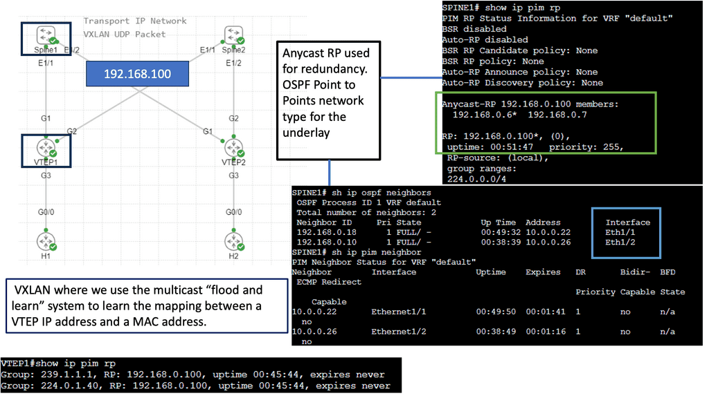
Example: VXLAN Flood and Learn

Understanding VXLAN Flood and Learn

VXLAN flood and learn handles unknown unicast, multicast, and broadcast traffic in VXLAN networks. It allows the network to learn and forward traffic to the appropriate destination without relying on traditional flooding techniques. By leveraging multicast, VXLAN flood and learn improves efficiency and reduces the network’s reliance on flooding every unknown packet.

Proper multicast group management is essential to implementing VXLAN flood and learning with multicast. VXLAN uses multicast groups to distribute unknown traffic efficiently within the network. 

VXLAN flood and learn with multicast offers several benefits for data center networks. Firstly, it reduces the flooding of unknown traffic, which helps minimize network congestion and improves overall performance. Additionally, it allows for better scalability by avoiding the need to flood every unknown packet to all VTEPs (VXLAN Tunnel Endpoint). This results in more efficient network utilization and reduced processing overhead.

Related: Before you proceed, you may find the following posts helpful for pre-information:

  1. Data Center Topologies
  2. Segment Routing
  3. What is OpenFlow
  4. Overlay Virtual Networks
  5. Layer 3 Data Center

What is VXLAN

Traditional layer two networks have issues because of the following reasons:

  • Spanning tree: Restricts links.
  • Limited amount of VLANs: Restricts scalability;
  • Large MAC address tables: Restricts scalability and mobility

Spanning-tree avoids loops by blocking redundant links. By blocking connections, we create a loop-free topology and pay for links we can’t use. Although we could switch to a layer three network, some technologies require layer two networking.

VLAN IDs are 12 bits long, so we can create 4094 VLANs (0 and 4095 are reserved). Data centers may need help with only 4094 available VLANs. Let’s say we have a service provider with 500 customers. There are 4094 available VLANs, so each customer can only have eight.

STP Path distribution

The Role of Server Virtualization

Server virtualization has exponentially increased the number of addresses in our switches’ MAC addresses. Before server virtualization, there was only one MAC address per switch port. With server virtualization, we can run many virtual machines (VMs) or containers on a single physical server. Virtual NICs and virtual MAC addresses are assigned to each virtual machine. One switch port must learn many MAC addresses.

A data center could connect 24 or 48 physical servers to a top-of-rack (ToR) switch. Since there may be many racks in a data center, each switch must store the MAC addresses of all VMs that communicate. Networks without server virtualization require much larger MAC address tables.

1st Lab Guide: VXLAN

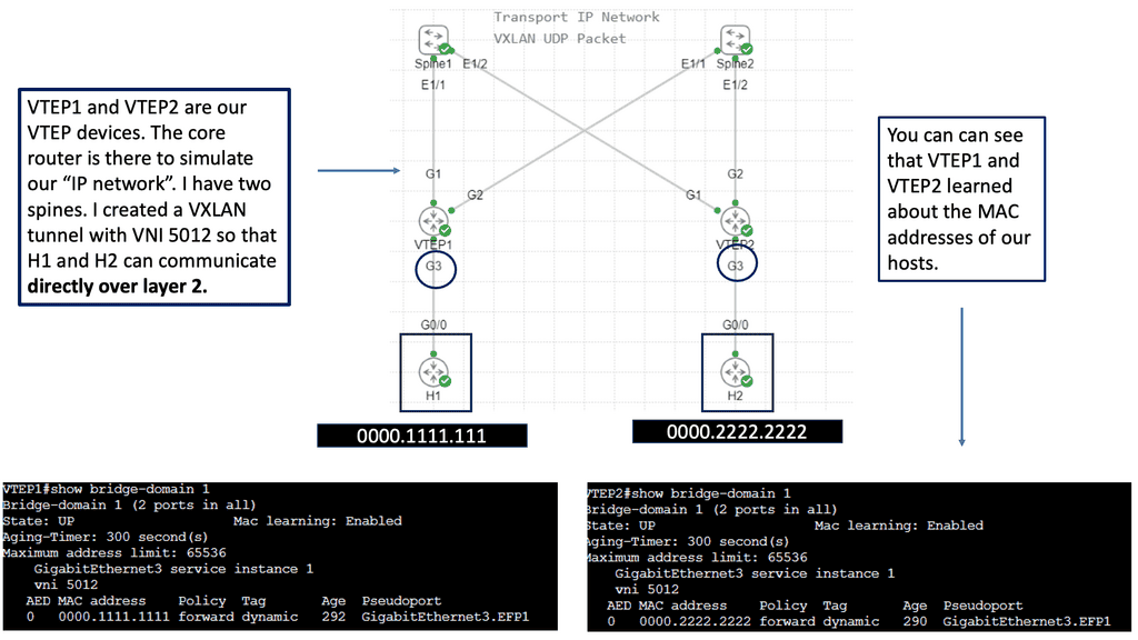
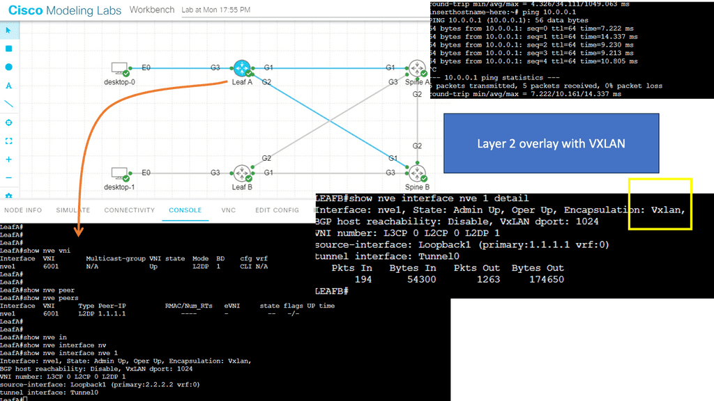
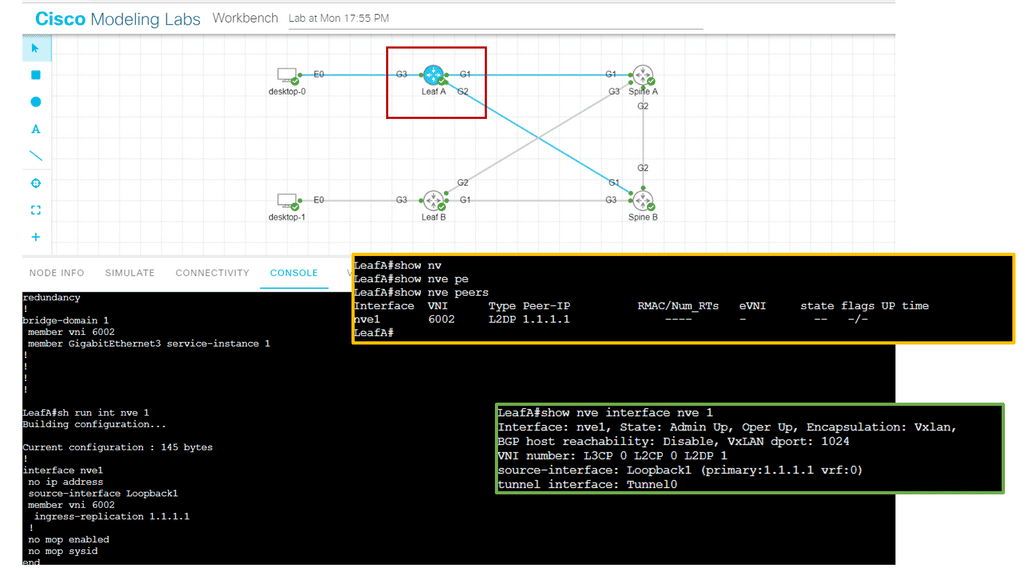
In the following lab, I created a Layer 2 overlay with VXLAN over a Layer 3 core. A bridge domain VNI of 6001 must match both sides of the overlay tunnel. What Is a VNI? The VLAN ID field in an Ethernet frame has only 12 bits, so VLAN cannot meet isolation requirements on data center networks. The emergence of VNI specifically solves this problem.

Note: The VNI

A VNI is a user identifier similar to a VLAN ID. A VNI identifies a tenant. VMs with different VNIs cannot communicate at Layer 2. During VXLAN packet encapsulation, a 24-bit VNI is added to a VXLAN packet, enabling VXLAN to isolate many tenants.

In the screenshot below, you will notice that I can ping from desktop 0 to desktop one even though the IP addresses are not in the routing table of the core devices, simulating a Layer 2 overlay. Consider VXLAN to be the overlay and the routing Layer 3 core to be the underlay.

VXLAN overlay
Diagram: VXLAN Overlay

In the following screenshot, notice that the VNI has been changed. The VNI needs to be changed in two places in the configuration, as illustrated below. Once changed, the Peers are down; however, the NVE  interface remains up. The VXLAN layer two overlay is not operational.

Diagram: Changing the VNI

How does VXLAN work?

VXLAN uses tunneling to encapsulate Layer 2 Ethernet frames within IP packets. Each VXLAN network is identified by a unique 24-bit segment ID, the VXLAN Network Identifier (VNI). The source VM encapsulates the original Ethernet frame with a VXLAN header, including the VNI. The encapsulated packet is then sent over the physical IP network to the destination VM and decapsulated to retrieve the original Ethernet frame.

Analysis:

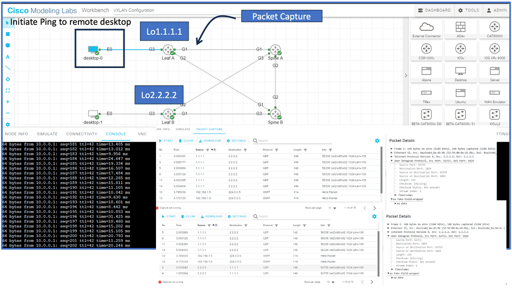
Notice below that it is running a ping from desktop 0 to desktop 1. The IP addresses assigned to this host are 10.0.0.1 and 10.0.0.2. First, notice that the ping is booming. When I do a packet capture on the links Gi1 connected to Leaf A, we see the encapsulation of the ICMP echo request and reply.

Everything is encapsulated into UDP port 1024. In my configurations of Leaf A and Leaf B, I explicitly set the VXLAN port to 1024.

VXLAN unicast mode

Back to Basics: VXLAN and Network Virtualization.

VXLAN and network virtualization

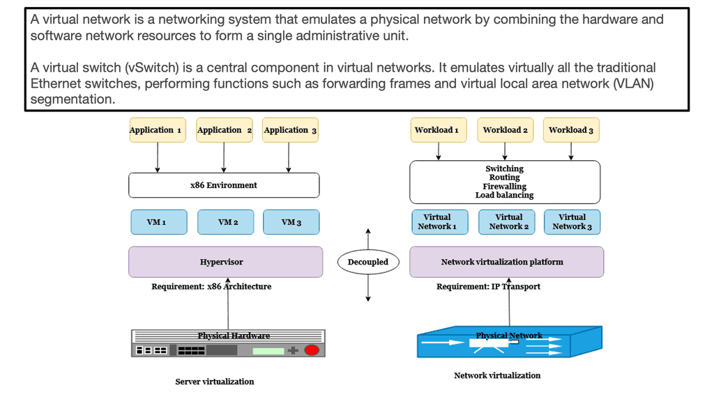
VXLAN is a form of network virtualization. Network virtualization cuts a single physical network into many virtual networks, often called network overlays. Virtualizing a resource allows it to be shared by multiple users. Virtualization provides the illusion that each user is on his or her resources.

In the case of virtual networks, each user is under the misconception that there are no other users of the network. To preserve the illusion, virtual networks are separated from one another. Packets cannot leak from one virtual network to another.

Network Virtualization
Diagram: Network Virtualization. Source Parallels

VXLAN Loop Detection and Prevention

So, before we dive into the benefits of VXLAN, let us address the basics of loop detection and prevention, which is a significant driver for using network overlays such as VLXAN. The challenge is that data frames can exist indefinitely when loops occur, disrupting network stability and degrading performance.

In addition, loops introduce broadcast radiation, increasing CPU and network bandwidth utilization, which degrades user application access experience. Finally, in multi-site networks, a loop can span multiple data centers, causing disruptions that are difficult to pinpoint. Overlay networking can solve much of this.

VXLAN vs VLAN

However, first-generation Layer-2 Ethernet networks could not natively detect or mitigate looped topologies, while modern Layer-2 overlays implicitly build loop-free topologies. Therefore, overlays do not need loop detection and mitigation as long as no first-gen Layer-2 network is attached. Essentially, there is no need for a VXLAN spanning tree.

So, one of the differences between VXLAN vs VLAN is that the VLAN has a 12-bit VID while VXLAN has a 24-bit VID network identifier, allowing you to create up to 16 million segments. VXLAN has tremendous scale and stable loop-free networking and is a foundation technology in the ACI Cisco.

Spanning tree VXLAN
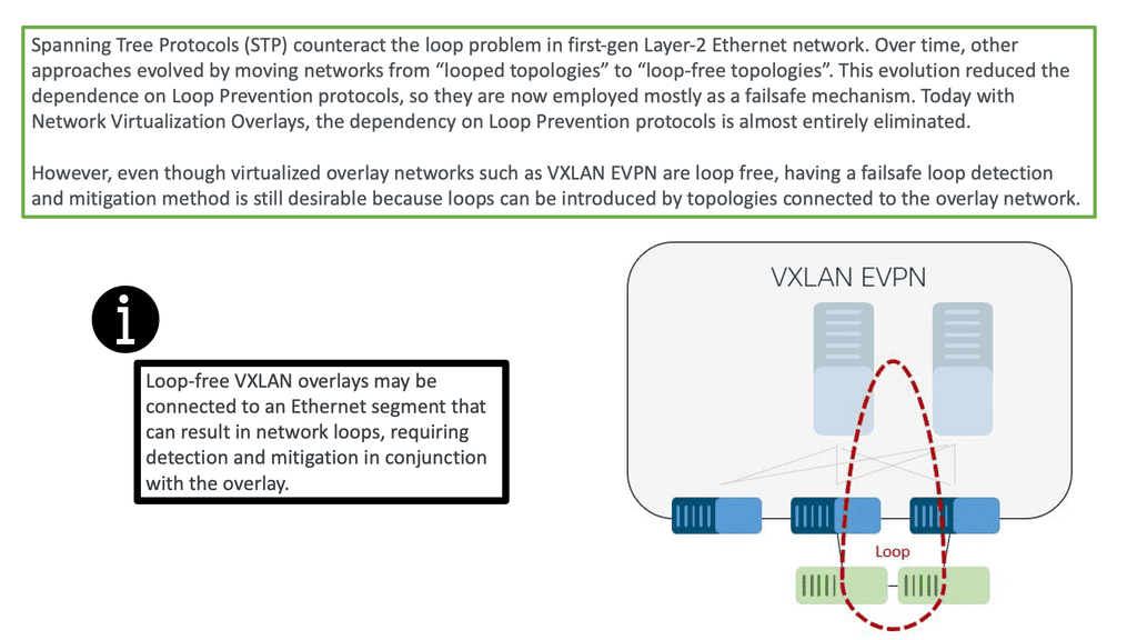
Diagram: Loop prevention. Source is Cisco

VXLAN and Data Center Interconnect

VXLAN has revolutionized data center interconnect by providing a scalable, flexible, and efficient solution for extending Layer 2 networks. Its ability to enable network segmentation, multi-tenancy support, and seamless mobility makes it a valuable technology for modern businesses.

However, careful planning, consideration of network infrastructure, and security measures are essential for successful implementation. By harnessing the power of VXLAN, organizations can achieve a more agile, scalable, and interconnected data center environment.

VXLAN vs VLAN: The VXLAN Benefits Drive Adoption

Introduced by Cisco and VMware and now heavily used in open networking, VXLAN stands for Virtual eXtensible Local Area Network. It is perhaps the most popular overlay technology for IP-based SDN data centers and is used extensively with ACI networks.

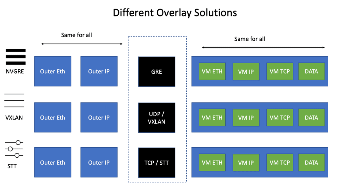
VXLAN was explicitly designed for Layer 2 over Layer 3 tunneling. Its early competition from NVGRE and STT is fading away, and VXLAN is becoming the industry standard. VLXAN brings many advantages, especially in loop prevention, as there is no need for a VXLAN spanning tree.

VXLAN Benefits
VXLAN Benefits: Scale and loop-free networks.

Today, overlays such as VXLAN almost eliminate the dependency on loop prevention protocols. However, even though virtualized overlay networks such as VXLAN are loop-free, having a failsafe loop detection and mitigation method is still desirable because loops can be introduced by topologies connected to the overlay network.

Loop prevention traditionally started with Spanning Tree Protocols (STP) to counteract the loop problem in first-gen Layer-2 Ethernet networks. Over time, other approaches evolved by moving networks from “looped topologies” to “loop-free topologies.

While LAG and MLAG were used, other approaches for building loop-free topologies arose using ECMP at the MAC or IP layers. For example, FabricPath or TRILL is a MAC layer ECMP approach that emerged in the last decade. More recently, network virtualization overlays that build loop-free topologies on top of IP layer ECMP became state-of-the-art.

What is VXLAN
What is VXLAN and the components involved?

VXLAN vs VLAN: Why Introduce VXLAN?

  1. STP issues and scalability constraints: STP is undesirable on a large scale and lacks a proper load-balancing mechanism. A solution was needed to leverage the ECMP capabilities of an IP network while offering extended VLANs across an IP core, i.e., virtual segments across the network core. There is no VXLAN spanning tree.
  2. Multi-tenancy: Layer 2 networks are capped at 4000 VLANs, restricting multi-tenancy design—a big difference in the VXLAN vs VLAN debates.
  3. ToR table scalability: Every ToR switch may need to support several virtual servers, and each virtual server requires several NICs and MAC addresses. This pushes the limits on the ToR switch’s table sizes. In addition, after the ToR tables become full, Layer 2 traffic will be treated as unknown unicast traffic, which will be flooded across the network, causing instability to a previously stable core.
STP Blocking.
Diagram: STP Blocking. Source Cisco Press free chapter.

VXLAN use cases

Use Case 

VXLAN Details

Use Case 1

Multi-tenant IaaS Clouds where you need a large number of segments

Use Case 2

Link Virtual to Physical Servers. This is done via software or hardware VXLAN to VLAN gateway

Use Case 3

HA Clusters across failure domains/availability zones

Use Case 4

VXLAN works well over fabrics that have equidistant endpoints

Use Case 5

VXLAN-encapsulated VLAN traffic across availability zones must be rate-limited to prevent broadcast storm propagation across multiple availability zones

What is VXLAN? The operations

When discussing VXLAN vs VLAN, VXLAN employs a MAC over IP/UDP overlay scheme and extends the traditional VLAN boundary of 4000 VLANs. The 12-bit VLAN identifier in traditional VLANs capped scalability within the SDN data center and proved cumbersome if you wanted a VLAN per application segment model. VXLAN scales the 12-bit to a 24-bit identifier and allows for 16 million logical endpoints, with each endpoint potentially offering another 4,000 VLANs.

While tunneling does provide Layer 2 adjacency between these logical endpoints and allows VMs to move across boundaries, the main driver for its insertion was to overcome the challenge of having only 4000 VLAN.

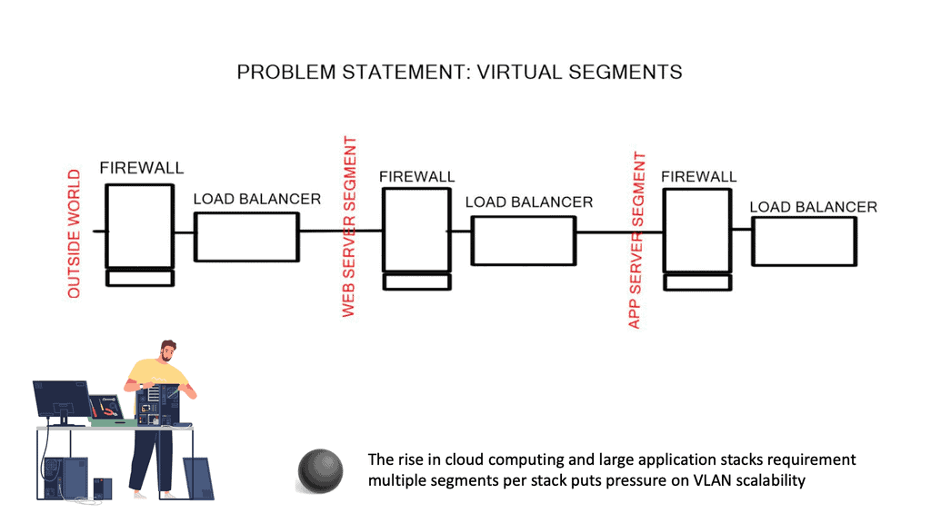
Typically, an application segment has multiple segments; between each segment, you will have firewalling and load-balancing services, and each segment requires a different VLAN. The Layer 2 VLAN segment transfers non-routable heartbeats or state information that can’t cross an L3 boundary. You will soon reach the 4000k VLAN limit if you are a cloud provider.

vxlan vs vlan
Multiple segments are required per application stack.

The control plane

The control plane is very similar to the spanning tree control plane. If a switch receives a packet destined for an unknown address, the switch will forward the packet to an IP address that floods the packet to all the other switches.

This IP address is, in turn, mapped to a multicast group across the network. VXLAN doesn’t explicitly have a control plane and requires an IP multicast running in the core for forwarding traffic and host discovery.

**Best practices for enabling IP Multicast in the core**

IP Multicast

In the Core

  1. Bidirectional PIM or PIM Sparse Mode
  1. Redundant Rendezvous Points (RP)
  1. Shared trees (reduce the amount of IP multicast state)
  1. Always check the IP multicast table sizes on core and ToR switches
  1. Single IP multicast address for multiple VXLAN segments is OK

The requirement for IP multicast in the core made VXLAN undesirable from an operation point of view. For example, creating the tunnel endpoints is simple, but introducing a protocol like IP multicast to a core just for the tunnel control plane was considered undesirable. As a result, some of the more recent versions of VXLAN support IP unicast.

VXLAN uses a MAC over IP/UDP solution to eliminate the need for a spanning tree. There is no VXLAN spanning tree. This enables the core to be IP and not run a spanning tree. Many people ask why VXLAN uses UDP. The reason is that the UDP port numbers cause VXLAN to inherit Layer 3 ECMP features. The entropy that enables load balancing across multiple paths is embedded into the UDP source port of the overlay header.

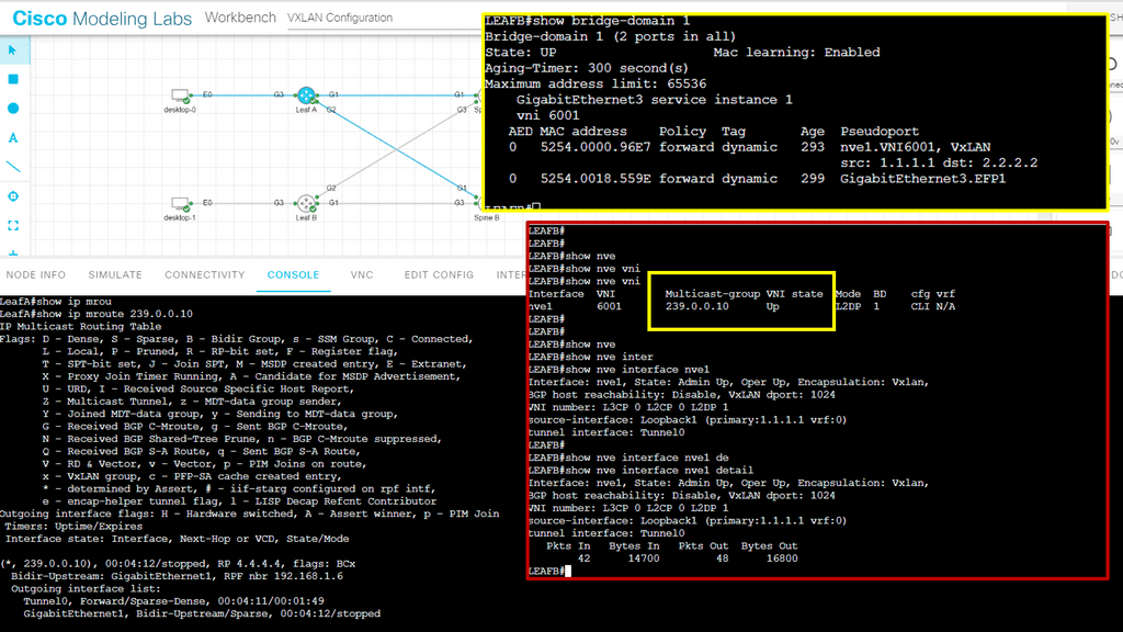
2nd Lab Guide: Multicast VLXAN

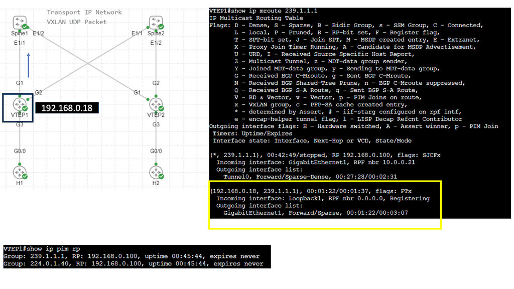
In this lab guide, we will look at a VXLAN multicast mode. The multicat mode requires both unicast and multicast connectivity between sites. Similar to the previous one, this configuration guide uses OSPF to provide unicast connectivity, and now we have an additional bidirectional Protocol Independent Multicast (PIM) to provide multicast connectivity.

This does not mean that you don’t have a multicast-enabled core. It would be best if you still had multicast enabled on the core. 

So we are not tunneling multicast over an IPv4 core without having multicast enabled on the core. I have multicast on all Layer 3 interfaces, and the mroute table is populated on all Layer 3 routers. With the command: Show ip mroute, we are tunneling the multicast traffic, and with the command: Show nve vni, we have multicast group 239.0.0.10 and a state of UP.

Multicast VXLAN
Diagram: Multicast VXLAN

VXLAN benefits and stability

The underlying control plan network impacts the stability of VXLAN and the applications running within it. For example, if the underlying IP network cannot converge quickly enough, VLXAN packets may be dropped, and an application cache timeout may be triggered.

The rate of change in the underlying network significantly impacts the stability of the tunnels, yet the rate and change of the tunnels do not affect the underlying control plane. This is similar to how the strength of an MPLS / VPN overlay is affected by the core’s IGP.

VXLAN Points

VXLAN benefits

VXLAN drawbacks

Point 1

Runs over IP Transport

 No control plane

Point 2

Offers a large number of logical endpoints 

Needs IP Multicast***

Point 3

Reduced flooding scope

No IGMP snooping ( yet )

Point 4

Eliminates STP

No Pvlan support

Point 5

Easily integrated over existing Core

Requires Jumbo frames in the core ( 50 bytes)

Point 6

Minimal host-to-network integration

No built-in security features **

Point 7

Not a DCI solution ( no arp reduction, first-hop gateway localization, no inbound traffic steering i.e, LISP )

** VXLAN has no built-in security features. Anyone who gains access to the core network can insert traffic into segments. The VXLAN transport network must be secure, as no existing firewall or intrusion prevention system (IPS) equipment can be seen in the VXLAN traffic.

*** Recent versions have Unicast VXLAN. Nexus 1000V release 4.2(1)SV2(2.1)

Updated: VXLAN enhancements

MAC distribution mode is an enhancement to VXLAN that prevents unknown unicast flooding and eliminates data plane MAC address learning. Traditionally, this was done by flooding to locate an unknown end host, but it has now been replaced with a control plane solution.

During VM startup, the VSM ( control plane ) collects the list of MAC addresses and distributes the MAC-to-VTEP mappings to all VEMs participating in a VXLAN segment. This technique makes VXLAN more optimal by unicasting more intelligently, similar to Nicira and VMware NVP.

ARP termination works by giving the VSM controller all the ARP and MAC information. This enables the VSM to proxy and respond locally to ARP requests without sending a broadcast. Because 90% of broadcast traffic is ARP requests ( ARP reply is unicast ), this significantly reduces broadcast traffic on the network.

Summary: What is VXLAN

VXLAN, short for Virtual Extensible LAN, is a network virtualization technology that has recently gained significant popularity. In this blog post, we will examine VXLAN’s definition, workings, and benefits. So, let’s dive into the world of VXLAN!

Understanding VXLAN Basics

VXLAN is an encapsulation protocol that enables the creation of virtual networks over existing Layer 3 infrastructures. It extends Layer 2 segments over Layer 3 networks, allowing for greater flexibility and scalability. By encapsulating Layer 2 frames within Layer 3 packets, VXLAN enables efficient communication between virtual machines (VMs) across physical hosts or data centers.

VXLAN Operation and Encapsulation

To understand how VXLAN works, we must look at its operation and encapsulation process. When a VM sends a Layer 2 frame, it is encapsulated into a VXLAN packet by adding a VXLAN header. This header includes information such as the VXLAN network identifier (VNI), which helps identify the virtual network to which the packet belongs. The VXLAN packet is then transported over the underlying Layer 3 network to the destination physical host, encapsulated, and delivered to the appropriate VM.

Benefits and Use Cases of VXLAN

VXLAN offers several benefits that make it an attractive choice for network virtualization. Firstly, it enables the creation of large-scale virtual networks, allowing for seamless VM mobility and workload placement flexibility. VXLAN also helps overcome the limitations of traditional VLANs by providing a much larger address space, accommodating the ever-growing number of virtual machines in modern data centers. Additionally, VXLAN facilitates network virtualization across geographically dispersed data centers, making it ideal for multi-site deployments and disaster recovery scenarios.

VXLAN vs. Other Network Virtualization Technologies

While VXLAN is widely used, it is essential to understand its key differences and advantages compared to other network virtualization technologies. For instance, VXLAN offers better scalability and flexibility than traditional VLANs. It also provides better isolation and segmentation of virtual networks, making it an ideal choice for multi-tenant environments. Additionally, VXLAN is agnostic to the physical network infrastructure, allowing it to be easily deployed in existing networks without requiring significant changes.

Conclusion:

In conclusion, VXLAN is a powerful network virtualization technology that has revolutionized how virtual networks are created and managed. Its ability to extend Layer 2 networks over Layer 3 infrastructures, scalability, flexibility, and ease of deployment make VXLAN a go-to solution for modern data centers. Whether for workload mobility, multi-site implementations, or overcoming VLAN limitations, VXLAN offers a robust and efficient solution. Embracing VXLAN can unlock new possibilities in network virtualization, enabling organizations to build agile, scalable, and resilient virtual networks.