
application traffic steering

Application Traffic Steering

NETWORK ENGINEERING · APPLICATION AWARENESS

Application Traffic Steering: From Flow Awareness to Intelligent Path Selection

Modern networks must do more than discover a destination and forward packets toward it. They must support applications with different performance requirements, direct traffic across available paths, preserve security policy and respond when network conditions change. Application traffic steering brings these decisions together by matching traffic flows with the paths and services best suited to their requirements.

Voice traffic may require low latency and jitter. Video applications need sufficient bandwidth and stable delivery, while transactional services may depend on predictable response times and secure access. Sending every flow along the same path without considering these differences can waste capacity or degrade the user experience.

Traffic steering introduces an additional layer of decision-making. Depending on the architecture, the network can classify applications, evaluate path performance, apply routing policies, distribute requests across servers or direct selected flows through security services. The mechanisms differ, but the engineering objective is consistent: make forwarding and delivery decisions that align with application needs.

From application requirements to a steering decision

01 · CLASSIFY Identify the flow Determine the application, endpoints, protocol and relevant identity or policy context.
02 · EVALUATE Assess conditions Compare available paths, performance metrics, service health and policy requirements.
03 · SELECT Choose an action Apply the relevant routing, load-balancing or service-steering mechanism.
04 · VERIFY Check the outcome Confirm forwarding, service availability and observed application performance.
Conceptual application traffic steering model
Application Flow
→
Classification
→
Policy
→
Path / Service
→
Forwarding

Why traditional routing is not the whole answer

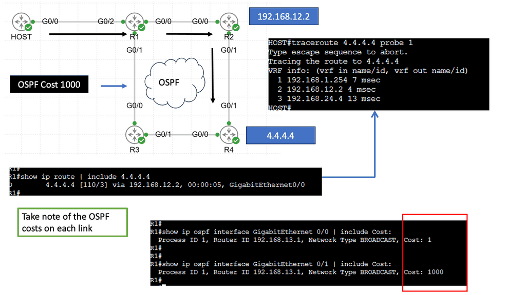
Traditional IP routing primarily selects a forwarding next hop using destination prefixes and the routing information available to the router. Routing protocols can respond to topology changes and select among alternative routes, but ordinary destination-based forwarding does not automatically distinguish every application sharing the same destination.

Application traffic steering can introduce additional classification, policy and performance inputs. SD-WAN systems may select between WAN paths using measured latency, jitter or loss. Load balancers distribute requests among backend servers. Policy-Based Routing can override normal routing decisions for matching traffic, while programmable SDN architectures can install more granular forwarding rules.

These approaches are related, but they are not interchangeable. A steering design must identify which device makes the decision, which information it can observe and which forwarding actions its platform supports.

BGP Application Traffic Steering

Border Gateway Protocol (BGP) provides an important foundation for traffic engineering between autonomous systems and across interconnected networks. By exchanging reachability information and applying routing policy, BGP allows network engineers to influence which advertised route is selected and how traffic enters or leaves a network.

BGP-based steering is not the same as an application-aware SD-WAN engine. BGP generally operates on network-layer reachability and path attributes, rather than independently measuring every application's real-time experience. However, carefully designed BGP policies can support application delivery objectives when traffic is separated into suitable prefixes or routing domains, or when BGP works alongside more granular steering mechanisms.

Dedicated BGP Learning Section
How BGP Influences Traffic Paths

Consider an enterprise network connected to two upstream providers. Both providers advertise reachability to a destination prefix. The enterprise can apply supported BGP policy to influence its preferred outbound route, while appropriately configured announcements and attributes can influence how remote networks select paths toward it.

Enterprise
→
Provider A
or
Provider B
→
Destination

The preferred path depends on routing policy, BGP attributes, reachability and the decision process at the relevant routers. Local preference can influence outbound path selection within an autonomous system; AS-path prepending may influence some remote networks' inbound route choices, but it is not a guarantee. BGP does not automatically select the lowest-latency application path.

BGP techniques explored in this article
Local preference Influence which eligible BGP route is preferred for outbound traffic within an autonomous system.
AS-path prepending Influence some remote networks' inbound route choices by advertising a longer AS path, subject to their policies.
More-specific prefixes Understand how prefix advertisements and longest-prefix matching can affect traffic destinations, within routing and operational constraints.
BGP Flow Specification Explore distribution of traffic-matching rules and supported actions for filtering or rate-limiting flows, subject to implementation and policy.

Performance and security must work together

A path that appears optimal from a latency or bandwidth perspective may still be unsuitable if it violates a security policy, traverses an unavailable service or fails a forwarding check. Effective steering therefore combines performance objectives with reachability, security controls and operational constraints.

This is especially important when BGP is part of the solution. A route can be valid and selected by BGP without guaranteeing that the application will achieve its required response time. Engineers must distinguish routing reachability from end-to-end application health.

Engineering principle

A routing decision determines where traffic can be forwarded. An application steering strategy determines which available path or service best satisfies the application's requirements, within the capabilities of the network and its configured policies.

What this learning journey covers

Path selection Understand application classification, path metrics, routing policies and steering decisions.
Load balancing Explore server selection, health checks and request distribution.
BGP traffic engineering Understand local preference, AS-path prepending, prefix selection and the limits of routing-based control.
Flow-level control Explore SDN, BGP Flow Specification, service insertion and policy-driven forwarding.
Interactive Learning · Application Traffic Steering
From Routing Policy to Steering Outcome

Continue through the article to examine how traffic is classified, how available paths are compared, how BGP policies influence route selection and how a steering decision can be tested against real forwarding and security constraints.

01 / Foundations

How Application Traffic Steering Works

Application traffic steering is the process of identifying a flow, evaluating its requirements and choosing an appropriate forwarding or application-handling decision. It brings policy into the path a request takes, rather than treating every flow as an identical destination lookup.

Start with the core model: classify traffic, evaluate policy, select an eligible path and verify the outcome. This foundation helps distinguish ordinary routing from policy-based routing, SD-WAN, load balancing and application-aware controls.

ClassifyEvaluateSelectVerify
Section 01 · Core Concepts

How Application Traffic Steering Works

Application traffic steering is the process of directing network traffic according to application requirements, network conditions and configured policy. Rather than treating every packet or connection identically, a steering system can identify relevant traffic, evaluate the available forwarding choices and apply an appropriate action.

The decision may happen at different points in the network. An edge router can apply Policy-Based Routing (PBR), an SD-WAN appliance can select a WAN path, a load balancer can choose a backend server, or a programmable network controller can install flow-specific forwarding rules. The mechanism depends on the problem being solved and the capabilities of the infrastructure.

The four stages of a steering decision

STAGE 01 Classify Identify the traffic using available information such as addresses, protocol, ports, application identity or policy tags.
→
STAGE 02 Evaluate Consider route availability, policy, link performance, destination health and service requirements.
→
STAGE 03 Select Choose an eligible next hop, WAN path, server or service chain according to the applicable rules.
→
STAGE 04 Forward and verify Apply the decision, then verify connectivity, service health and application performance.

What information can influence the decision?

Steering decisions are only as good as the information available to the component making them. Some mechanisms rely primarily on packet headers and routing policy. Others incorporate application recognition, active probes, telemetry, user identity or the health of destination services.

Traffic and policy context

Source and destination prefixes, transport protocol, ports, routing attributes, access rules and application classification can determine which policy applies to a flow.

Path and service conditions

Depending on the platform, measured latency, jitter, packet loss, bandwidth, link state and backend health can help determine which available path or service is suitable.

Important distinction: routing versus steering

Routing establishes reachability and selects routes according to the routing information and decision rules in use. Application traffic steering adds classification or policy objectives that influence how selected traffic is handled. A routing protocol does not automatically provide application awareness or real-time performance measurement.

Three common steering approaches

  • Policy-Based Routing: Matches defined traffic criteria and directs matching packets through a configured next hop or forwarding action, where supported.
  • SD-WAN path selection: Can use link measurements and application policies to choose between available WAN transports.
  • Load balancing: Distributes connections or requests across eligible servers or service endpoints, often using health checks and a configured selection algorithm.

BGP can also influence traffic paths by exchanging reachability and applying attributes and routing policy. For example, local preference can influence outbound route selection within an autonomous system, while AS-path prepending may affect some remote networks' inbound choices. These techniques operate at the routing-policy level and do not, by themselves, guarantee the lowest-latency path for a particular application.

Example: steering traffic away from a degraded link

Imagine a branch office with two WAN connections. Both links are available, but the primary connection begins experiencing increased packet loss. A steering system with suitable measurement and policy capabilities may direct eligible application traffic to the secondary connection. When the primary link meets the configured recovery conditions, the system may return traffic to it.

Illustrative decision sequence

Observe: The primary link's measured loss exceeds the configured threshold.
Evaluate: The secondary link is available and satisfies the applicable policy.
Steer: Eligible traffic is directed through the secondary link.
Verify: Monitoring confirms the forwarding change and checks whether application performance improves.

This is a conceptual example. Actual detection intervals, thresholds, failover behaviour and recovery rules depend on the implementation.

Design considerations

  • Define the objective. Decide whether the priority is availability, latency, loss, cost, security or a combination of factors.
  • Understand the control point. Identify which router, SD-WAN appliance, controller or load balancer can enforce the decision.
  • Check the return path. Asymmetric routing, stateful firewalls and session persistence can affect whether a change works correctly.
  • Validate the outcome. A selected route or link is not proof that application performance has improved; measure the result.
Key takeaway

Application traffic steering connects traffic classification, policy, path selection and verification. Understanding where each decision is made is the first step toward choosing the right mechanism, whether that is PBR, SD-WAN, load balancing, BGP policy or programmable flow-level control.

Network Insight / Application Traffic Steering Lab 01

Classify. Decide. Steer. Verify.

Follow an application flow through a simplified steering system. Change the policy to see how traffic classification, path selection and health checks influence the illustrative forwarding decision.
Ready
Traffic Decision Path
0 / 6
◉
APPLICATION
10.10.10.25
HTTPS request
◈
STEERING ENGINE
Classify + evaluate
⇢
PATH A
Preferred route
Awaiting traffic
Start the simulation to inspect the application flow.
Flow Classification
Illustrative metadata
Source10.10.10.25
Destination203.0.113.40
ApplicationHTTPS / Business
PriorityHigh
Decision stateNot evaluated
Available Paths
Sample telemetry
A
Path A · Premium WAN
Latency 24 ms · Cost high · Healthy
B
Path B · Broadband
Latency 38 ms · Cost low · Healthy
C
Path C · Backup link
Latency 71 ms · Cost medium · Healthy
Steering Timeline
Six decision stages
01
Ingress
The application flow enters the network.
02
Classify
The system identifies the flow using available metadata and policy.
03
Evaluate
The selected policy compares eligible paths and their relevant metrics.
04
Select
A path is chosen according to the current steering policy.
05
Forward
The flow is forwarded through the selected path.
06
Verify
The system checks the outcome and can reconsider the path if conditions change.
Decision Telemetry
Live interpretation
Current Event
Press Step Forward to begin
Observe how the steering process moves from classification to forwarding.
Simulation Progress
Engineering takeaway: traffic steering is a policy decision process. The best path depends on the application requirements, available measurements and configured rules.
02 / Policy and Classification

Policy-Based Routing: Classifying Traffic and Choosing a Path

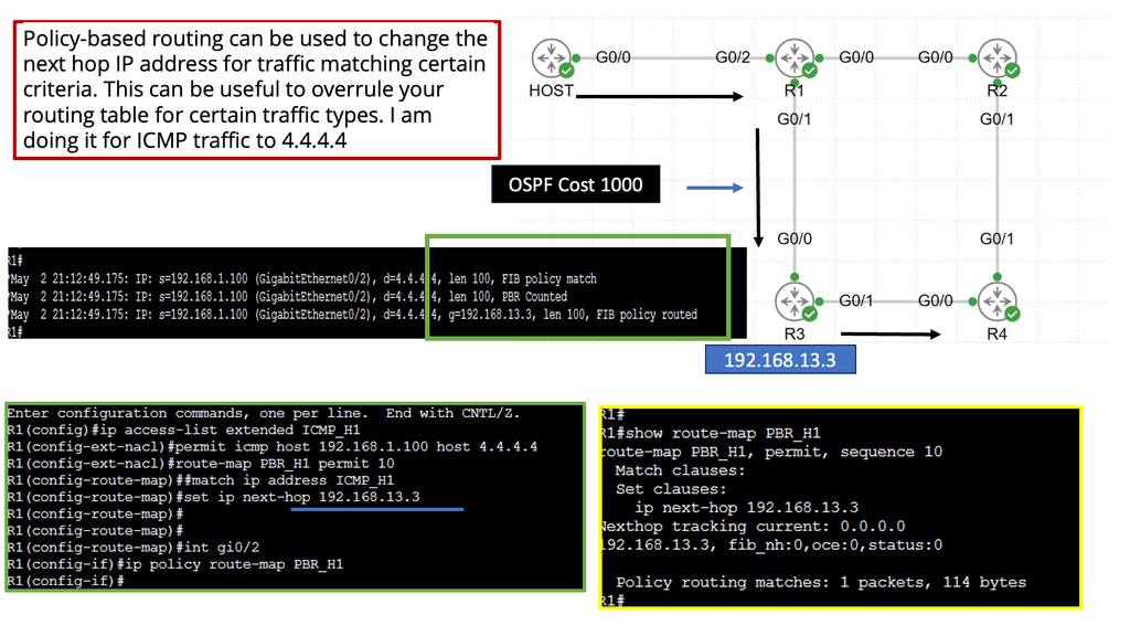
Policy-Based Routing (PBR) allows selected traffic to follow a policy-defined forwarding decision rather than relying exclusively on the normal destination-based route lookup. Rules may match supported attributes such as source address, destination address, protocol or transport ports.

PBR is useful when different traffic classes need different next hops or handling. Its effectiveness depends on correct match conditions, reachable next hops, suitable fallback behaviour and careful validation of both forward and return traffic.

Match conditionsPolicy rulesNext-hop choiceFallback behaviour
Section 02 · Traffic Policy

Policy-Based Routing: Classifying Traffic and Choosing a Path

Policy-Based Routing (PBR) allows a network device to make forwarding decisions using configured traffic-matching rules rather than relying exclusively on the destination-based route lookup. It can direct selected traffic toward a particular next hop or interface when the platform, policy and forwarding design support that action.

PBR is useful when different traffic classes need different treatment. For example, an organisation might direct traffic from a particular department through a security appliance, send selected application traffic over a dedicated WAN connection, or route traffic from a specific subnet toward a service network.

How a PBR decision is made

01 · MATCH Identify traffic Compare packet attributes against configured match criteria.
→
02 · APPLY Evaluate policy Determine whether a routing policy applies to the packet.
→
03 · SELECT Choose forwarding Use the configured next hop, interface or supported action.
→
04 · CHECK Verify delivery Confirm reachability and check that the chosen path works as intended.

What can a policy match?

The exact matching options depend on the vendor and platform. Common implementations use access control lists or equivalent classifiers to identify traffic using network and transport-layer fields.

Network layer
Source and destination

Match source or destination IP prefixes to apply different forwarding policies to users, subnets or destination networks.

Transport layer
Protocol and ports

Where supported, distinguish traffic by protocol and port, such as selected TCP or UDP flows.

Policy context
Traffic classes

Use configured classifiers, markings or other supported criteria to associate traffic with a forwarding policy.

Operational context
Next-hop availability

Use platform-supported tracking or failover mechanisms where available so a policy does not blindly depend on an unusable next hop.

Example: sending selected traffic through a preferred path

Consider a branch router connected to two upstream paths. A defined traffic class should use the preferred path, while other traffic continues to use the normal routing table. PBR can implement this separation when the router supports the required matching and forwarding actions.

Illustrative forwarding policy
Traffic received by branch router | v Match configured source / destination / protocol criteria | +-- Match --> Apply policy-selected next hop | +-- No match --> Use normal destination-based routing

This is a conceptual flow, not vendor-specific configuration. The actual processing order, supported actions and fallback behaviour must be confirmed for the router and software release in use.

PBR versus ordinary destination-based routing

Destination-based routing

The device normally consults its forwarding information to select the best matching destination prefix and corresponding next hop. The result is primarily determined by destination reachability and the routing information installed in the forwarding table.

Policy-Based Routing

Matching traffic can receive a policy-defined forwarding treatment that differs from the normal destination-based choice. Traffic that does not match the policy generally follows the platform's configured normal routing behaviour.

Important operational distinction

PBR does not automatically discover the best-performing path. A configured policy may select a next hop even when that path is congested or unavailable unless suitable tracking, failover and verification mechanisms are configured.

Where PBR fits in application traffic steering

PBR is particularly useful when the steering requirement can be expressed as a clear rule and enforced at a suitable network device. It can provide deterministic traffic handling, but it is not inherently equivalent to deep application recognition or continuous performance-aware path selection.

  • Use PBR when defined traffic matches must use a particular supported forwarding path.
  • Consider SD-WAN when path decisions need to incorporate measured WAN performance and application policies.
  • Consider load balancing when the decision is which backend server or service endpoint should receive a request.
  • Consider BGP policy when the objective is to influence route selection and reachability across BGP-controlled networks.
Key takeaway

PBR turns a traffic-matching rule into a forwarding decision. Successful deployment requires precise match criteria, a valid next hop, a defined fallback strategy and operational checks that confirm traffic reaches its intended destination.

Network Insight / Application Traffic Steering Lab 02

Policy-Based Routing: Match the Flow, Choose the Path

Explore how a router can use configured policy to steer selected traffic toward a particular next hop instead of relying solely on the ordinary destination-based routing decision.
Ready
Policy Decision Topology
0 / 6
◉
BUSINESS LAN
10.10.10.0/24
◇
EDGE ROUTER
PBR policy
⇢
WAN A
192.0.2.1
WAN A · Primary
Next hop 192.0.2.1
Preferred for selected classes
WAN B · Alternate
Next hop 198.51.100.1
Alternate policy path
Key concept: PBR matches traffic against configured criteria and applies a policy action, such as setting a next hop. Exact match fields and actions depend on the router platform and configuration.
Matched Traffic
Example packet
Source subnet10.10.10.0/24
Destination203.0.113.80
Traffic classBusiness
Policy matchAwaiting inspection
Policy actionNot applied
Selected next hopNot selected
Illustrative Policy Rules
First matching rule
Rule 10 · Real-time
HIGH PRIORITY
Voice traffic → WAN A, when the policy match succeeds.
Rule 20 · Business
BUSINESS
Business application traffic → WAN A.
Rule 30 · Bulk
COST AWARE
Bulk transfer traffic → WAN B.
Default
FALLBACK
Unmatched traffic follows the ordinary routing decision in this model.
Packet Processing Timeline
Match → action → forwarding
01
Ingress
A packet arrives at the router from the selected source network.
02
Classify
The packet is checked against the configured policy match criteria.
03
Match
A rule matches the illustrative traffic class, or the packet uses the fallback behaviour.
04
Action
The policy selects a next hop for traffic matching the rule.
05
Forward
The router forwards the packet toward the selected next hop, if the action can be applied.
06
Verify
The outcome is checked conceptually; real forwarding and failover depend on platform behaviour and configuration.
PBR Lab Telemetry
Live interpretation
Current Event
Press Step Forward to begin
Select a traffic class and step through the policy decision.
Simulation Progress
Policy Result
No decision yet
The selected rule and next hop will appear as the simulation advances.
03 / Performance and Path Quality

SD-WAN and Performance-Based Path Selection

SD-WAN can combine centralised policy with measurements from available network paths. Depending on the platform, information such as latency, jitter, packet loss and link health can help determine whether a path is suitable for a particular application or traffic class.

The key difference from conventional routing is the use of application requirements and path-quality information in steering decisions. Performance-based steering still needs thresholds, failover rules and recovery logic to avoid unstable path changes.

LatencyJitterPacket lossFailover and recovery
Section 03 · Performance-Aware Networking

SD-WAN and Performance-Based Path Selection

Software-Defined Wide Area Networking (SD-WAN) can extend traffic steering beyond static path preferences by combining application policies with information about available WAN connections. Depending on the implementation, an SD-WAN edge can evaluate link measurements, identify application traffic and select an eligible path according to configured service requirements.

A branch office might have broadband, business fibre and an MPLS connection. These links can differ in cost, capacity, latency and reliability. Instead of treating one connection as universally best, an SD-WAN policy can determine which transport is suitable for each traffic class and respond when conditions change.

Which measurements matter?

Responsiveness
Latency

Measures the time taken for traffic to travel between measurement points. Lower latency can benefit interactive applications such as voice, remote desktops and transactional systems.

Consistency
Jitter

Describes variation in packet delay. Unstable delay can affect real-time audio and video even when average latency appears acceptable.

Reliability
Packet loss

Indicates packets that fail to reach the measurement destination. Loss can degrade voice and video and trigger retransmissions for applications using reliable transport protocols.

Capacity
Available bandwidth

Helps determine whether a path can support the expected traffic demand. Capacity estimates must be interpreted alongside congestion, shaping and competing traffic.

From telemetry to a forwarding action

01 · MEASURE Monitor links Collect supported path metrics using probes or other telemetry.
→
02 · CLASSIFY Identify traffic Associate traffic with an application or configured policy class.
→
03 · COMPARE Check requirements Compare eligible paths against policy thresholds and preferences.
→
04 · STEER Select a path Apply the configured path choice and continue monitoring conditions.

Example: choosing between two WAN paths

Imagine that a branch uses two WAN transports. The primary link normally carries voice and business application traffic, but its measured loss increases. The secondary link remains within the policy's acceptable performance limits. An SD-WAN implementation may steer the affected application traffic to the secondary path, provided the configured policy and platform support that behaviour.

Illustrative path comparison
WAN Path A · Primary
Loss above policy threshold

The connection is still reachable, but its measured quality no longer satisfies the application's configured requirements.

WAN Path B · Alternative
Within policy limits

The alternative connection is eligible for the affected traffic, so the steering policy may prefer it until conditions change.

The key point is that link availability and link suitability are different questions. A link can remain operational while its measured performance falls outside the requirements of a particular application.

No specific latency, jitter or loss values are assumed here. Thresholds and failover behaviour are implementation- and policy-dependent.

Different applications need different policies

Voice and real-time collaboration

Prioritise acceptable latency, jitter and loss. A high-capacity path may still be unsuitable if delay variation is excessive.

Bulk transfers and backups

Consider available capacity, transfer duration and cost. These applications may tolerate more delay than interactive services.

Business-critical applications

Define acceptable performance and availability requirements, with clear rules for alternate paths and recovery.

Guest and general internet traffic

Apply appropriate access, capacity and cost policies without automatically giving every flow the same path preference.

Failover is only part of the design

Steering traffic away from a degraded connection is useful, but the policy must also define what happens when the preferred path recovers. Without suitable thresholds, hold-down periods or other stability controls, repeated changes can cause unnecessary path switching. The precise controls available depend on the platform.

  • Define thresholds: Specify which measured conditions make a path acceptable or unsuitable.
  • Plan recovery: Determine when traffic should return to the preferred path after performance improves.
  • Check capacity: Ensure the alternate path can handle the traffic it may receive during degradation or failure.
  • Verify application health: Confirm that the path change actually improves the user experience.
SD-WAN and BGP solve different parts of the problem

SD-WAN can make policy-driven path choices using application classification and measured transport performance. BGP exchanges reachability and applies routing policy to select routes. They can complement each other, but BGP alone does not provide the same application-level measurement and steering behaviour as a performance-aware SD-WAN system.

Key takeaway

Performance-based steering connects path measurement to application policy. It can help networks respond to changing WAN conditions, but effective deployment requires realistic thresholds, stable failover behaviour, sufficient backup capacity and end-to-end verification.

Network Insight · Interactive Lab 03

SD-WAN Performance-Based Path Selection

Watch an application flow get matched to a policy, evaluated against live link conditions, and forwarded over a selected WAN path.

Ready to evaluate
01 / Overlay and underlay view
Phase 0 of 5
▦
Branch LAN Application flow
→
◇
SD-WAN Edge Policy engine
→
◎
Cloud / DC Destination
Logical overlay: the edge selects an eligible transport path based on policy and measured conditions.
02 / WAN underlay telemetry
Illustrative measurements
Awaiting traffic classification

Choose an application profile, then step through the path-selection process.

04 / Decision sequence
Step-by-step
1
Classify the applicationIdentify the traffic profile and its requirements.
2
Measure link conditionsCompare latency, loss, jitter and availability.
3
Evaluate policy and SLACheck which paths satisfy the selected policy.
4
Select the transportChoose the best eligible WAN path.
5
Forward and verifyShow the chosen path and simulated outcome.
05 / Event timeline
0 events
Lab initialized
Select an application and step forward to begin.
Engineering note: This is an illustrative policy model, not a live SD-WAN controller. Real products differ in their SLA probes, thresholds, path scoring, failover timers, hysteresis and load-sharing behaviour. A policy may prefer a path only while that path remains eligible; if no path satisfies the policy, the result depends on the configured fallback behaviour.
04 / Application Delivery

Load Balancing: Steering Requests to Healthy Services

Load balancing distributes incoming requests or connections across a group of service instances. Instead of sending every request to one endpoint, a load balancer can select a backend according to its configured algorithm, health status and other supported criteria.

Layer 4 load balancing generally uses transport-level connection information, while Layer 7 balancing can make decisions using application protocol details. Both can improve availability and resource utilisation, but neither removes the need for health checks, capacity planning and session-handling decisions.

Backend selection Health checks Layer 4 and Layer 7 Session persistence
Section 04 · Application Delivery

Load Balancing: Steering Requests to Healthy Services

Load balancing distributes client connections or application requests across multiple servers or service endpoints. Rather than allowing every request to depend on a single backend, a load balancer selects an eligible destination according to its configured algorithm, health information and any applicable session or routing policy.

This is a different steering problem from selecting a WAN path or choosing a BGP route. Load balancing focuses on where a request or connection should be delivered within an application service. It can improve capacity utilisation and availability, but the result depends on how backend health, session state and application behaviour are handled.

A typical application delivery architecture

Client-to-service request flow
Client / Application User
↓
Load Balancer · Selects an Eligible Backend
↓
Application Server A Backend endpoint
Application Server B Backend endpoint
Application Server C Backend endpoint

The load balancer receives a request or connection, applies its selection logic and directs it to a backend that is eligible to serve the traffic. The exact forwarding model depends on whether the implementation operates at Layer 4, Layer 7 or another supported service-delivery layer.

Layer 4 and Layer 7 load balancing

Transport-aware
Layer 4 load balancing

Uses transport and network connection information, commonly including IP addresses, protocol and TCP or UDP ports. It can distribute connections without needing to interpret the full application request.

Application-aware
Layer 7 load balancing

Can make decisions using application-layer information such as HTTP hostnames, URL paths, headers or other supported request attributes. This enables more granular application delivery policies.

Layer 7 visibility can support more detailed routing decisions, but it introduces additional considerations, including TLS termination, certificate handling, request parsing and the privacy of application data. The chosen design should match the requirements of the service.

Common backend selection methods

Round robin

Distributes new selections sequentially across eligible backend servers. It is simple, but does not inherently account for different server capacities or current workloads.

Weighted distribution

Assigns different selection weights to backends. A server with a higher configured weight can receive a larger share of selections, depending on the algorithm.

Least connections

Selects a backend based on its active connection count, where supported. This can help distribute connection load but may not accurately represent the processing cost of every request.

Hash-based selection

Uses a key such as a client address or request attribute to select a backend. Depending on the method, this can help maintain consistency for related requests.

Health checks: avoid sending traffic to failed backends

A backend can remain reachable at the IP layer while its application is unable to serve requests correctly. Load balancers therefore commonly use health checks to determine whether a destination should remain in the eligible backend pool.

  • Connectivity checks: Verify that a supported network or transport endpoint responds.
  • Application checks: Request a health endpoint or test a service-specific condition when configured.
  • Pool membership: Remove unhealthy destinations from new selections and restore them according to the configured recovery rules.
  • Capacity awareness: Consider whether the remaining healthy servers can handle the additional traffic.
Health does not always mean application success

A successful health check confirms only the conditions that it actually tests. A basic TCP check may pass while a database dependency, login workflow or critical application function is failing. Health checks should be designed to reflect the service's real operational needs.

Session persistence and state

Some applications store session state locally on a particular server. If successive requests from the same user are sent to different backends, the application may lose access to that state unless the architecture supports shared sessions or another state-management mechanism.

Session persistence, sometimes called stickiness, can help keep related requests associated with a backend. However, it can also create uneven load distribution or reduce flexibility during a failure. Shared session storage and stateless application design can reduce dependence on persistent backend selection.

Load balancing versus network traffic steering

Network path steering

Chooses how traffic traverses the network, for example by selecting a WAN transport, applying PBR or influencing route selection through BGP policy.

Application load balancing

Chooses which eligible server or service endpoint receives a request or connection. It operates at the application delivery layer rather than simply selecting an IP route.

These mechanisms can work together. Routing and SD-WAN determine how traffic reaches the application delivery infrastructure, while the load balancer selects a backend. A successful end-to-end design needs both layers to be reachable and correctly configured.

Design checks before deployment

  • Capacity: Confirm that the load balancer and healthy backends can support expected traffic and failure scenarios.
  • Protocol behaviour: Check TLS termination, connection reuse, timeouts and supported application protocols.
  • Failure handling: Define how unhealthy backends are detected, excluded and returned to service.
  • Observability: Monitor backend health, request errors, response times and distribution across the server pool.
Key takeaway

Load balancing steers requests or connections across eligible application backends. Effective application delivery combines an appropriate selection algorithm, meaningful health checks, session-state planning and monitoring. It complements network-level steering but solves a different part of the delivery problem.

Network Insight · Interactive Lab 04

Load Balancing and Application Delivery

Send application requests through a load balancer, observe server selection, and test how health checks change traffic distribution.

Ready for requests
01 / Application delivery path
0 requests processed
▦
Clients HTTPS requests
→
⇄
Load Balancer Round robin
→
▣
Application Server pool
APP-01HEALTHY
Load0%
Requests0
APP-02HEALTHY
Load0%
Requests0
APP-03HEALTHY
Load0%
Requests0
Green border = server selected for the latest request. Red status = unavailable and excluded from new selections.
02 / Pool statistics
Current simulation
Total requests0
Successful0
Failed / rejected0
Awaiting first request

Select a balancing algorithm, then send a request to see which healthy server receives it.

04 / Request processing
Illustrative sequence
1
Receive requestA client sends an application request to the service endpoint.
2
Check server healthOnly eligible pool members can receive new traffic.
3
Apply balancing policyThe configured algorithm selects a server.
4
Forward requestThe load balancer sends the request to the selected server.
5
Record outcomeThe simulation updates request counts and pool load.
05 / Event timeline
0 events
Lab initialized
Ready to simulate application requests.
Engineering note: This is a simplified application-delivery model. Real load balancers may use connection counts, response times, weights, cookies, source affinity, consistent hashing, health-check thresholds and draining behaviour. A health check does not guarantee that every application transaction will succeed, and persistence rules can affect distribution even when multiple servers are healthy.
05 / Programmable Networking

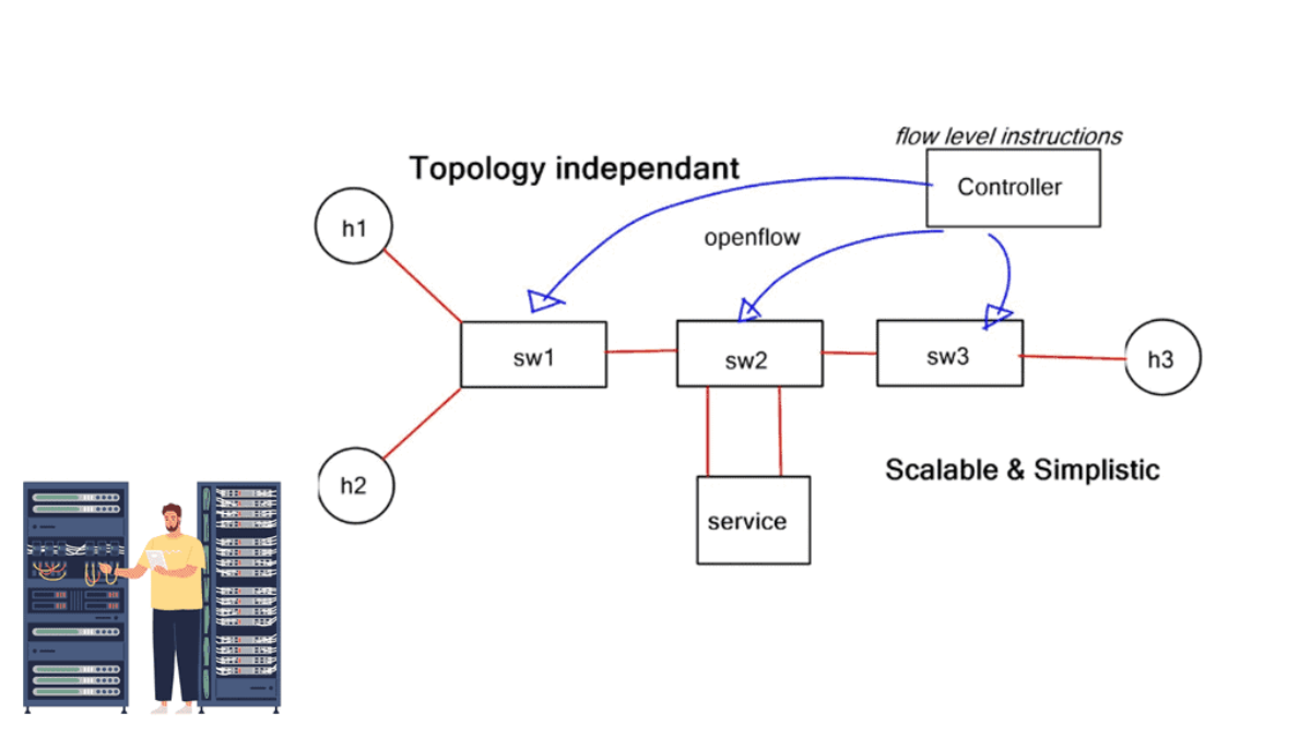
SDN, OpenFlow and Flow-Level Traffic Steering

Software-Defined Networking introduces programmable approaches to network control. In compatible architectures, a controller can coordinate forwarding policies and install rules that classify selected packets and specify how those packets should be processed.

OpenFlow is one example of a protocol used to manage flow-table entries on supported switches. This section explores match/action logic, rule priorities and installation strategies, along with the operational checks needed to ensure that programmed forwarding matches the intended policy.

Control plane Flow tables Match/action rules Programmable paths
Section 05 · Programmable Networking

SDN, OpenFlow and Flow-Level Traffic Steering

Software-Defined Networking (SDN) introduces a programmable approach to network control. Instead of configuring every forwarding decision only through individual device interfaces, an SDN architecture can use a controller or network application to define policies and coordinate forwarding behaviour across supported network devices.

This approach can support more granular steering than conventional destination-based routing alone. Depending on the platform and forwarding technology, traffic can be classified using fields such as source and destination addresses, protocol and transport ports, then handled using rules that specify the permitted forwarding actions.

Separating network control from packet forwarding

Control plane
Controller and policy logic

Computes or coordinates forwarding policies, maintains a view of relevant network state and communicates supported rules to network devices through the applicable control interface.

Data plane
Switches and forwarding devices

Processes packets using installed forwarding entries, match criteria and supported actions. The device performs the actual packet handling at forwarding time.

The separation is conceptual rather than absolute. Real networks still require mechanisms for topology discovery, reachability, failure handling, rule installation and coordination between control and forwarding components. SDN platforms differ in how they implement these functions.

How a programmable steering rule is applied

01 · IDENTIFY Classify the flow Determine which packet fields or traffic conditions match the policy.
→
02 · COMPUTE Determine the action Apply controller logic, topology information and policy constraints.
→
03 · INSTALL Program forwarding Install or update a supported rule on the relevant forwarding device.
→
04 · PROCESS Handle packets Match packets against the installed rules and execute the configured action.

OpenFlow and match/action forwarding

OpenFlow is a protocol historically associated with SDN that allows a controller to communicate with compatible switches and manage supported flow-table entries. An entry can contain match fields, priority, counters and instructions or actions that determine how matching packets are processed.

Depending on the OpenFlow version and switch capabilities, actions may include forwarding to a port, dropping a packet, modifying supported header fields or directing processing to another table. The precise capabilities are version- and implementation-dependent.

Conceptual flow-table entry
MATCH Source: 10.10.10.0/24 Destination: 198.51.100.20 Protocol: TCP Port: 443 ACTION Forward using the configured permitted output path

This is an illustrative rule, not executable OpenFlow syntax. It shows how selected traffic can be distinguished from other packets and associated with a forwarding action supported by the device.

The example assumes the platform supports the specified match fields and a valid forwarding action. A production rule also needs suitable priority, table behaviour and lifecycle management.

Why rule priority and table processing matter

A programmable switch may contain many flow entries. Multiple entries can potentially match the same packet, so priority and table-processing rules determine which entry applies and how processing continues. Broad rules can unintentionally override more specific policies if they are installed with inappropriate priorities or instructions.

  • Specificity: Ensure that intended traffic matches the correct entry rather than an unrelated broad rule.
  • Priority: Use a deliberate priority strategy for overlapping match conditions.
  • Fallback: Define the intended behaviour when no specific entry matches.
  • Lifecycle: Consider timeouts, stale entries, updates and cleanup when policies change.

Reactive and proactive rule installation

Reactive approach

A device or controller interaction triggered by traffic can lead to a rule being installed after the relevant flow is first encountered. This can provide flexibility but may introduce initial setup delay and control-plane workload.

Proactive approach

Rules are installed before the associated traffic arrives. This can reduce first-packet setup delays, provided the required policies, topology information and forwarding entries are already available.

Where programmable flow steering is useful

Traffic isolation

Apply distinct forwarding policies to selected traffic classes or network segments, subject to the platform's match and action support.

Service insertion

Direct eligible traffic through a firewall, inspection system or other service before it reaches its destination.

Path engineering

Select a supported forwarding path based on controller policy and network state, rather than relying solely on the normal forwarding choice for the destination.

Policy experimentation

Test traffic classification and forwarding changes in a controlled lab before considering a production deployment.

Programmability does not remove operational constraints

A controller can only install actions supported by the target devices, and the resulting path must still be valid. Rule conflicts, stale state, control-channel failures and incomplete topology information can affect traffic delivery. Validate both the controller's policy and the forwarding behaviour of the devices.

SDN flow rules versus BGP policy

BGP primarily exchanges reachability information and applies routing attributes and policy to select routes. Programmable flow steering can operate at a finer granularity when the forwarding platform supports the required packet matches and actions.

The two approaches can coexist. BGP can provide reachability between routing domains, while an SDN-controlled data plane applies more specific forwarding rules within a network. Their responsibilities should be clearly separated to avoid conflicting decisions or unexpected forwarding behaviour.

Engineering checks

  • Device compatibility: Confirm supported protocols, match fields, actions, table capacity and controller integration.
  • Failure behaviour: Decide what happens when the controller or its communication channel becomes unavailable.
  • Rule consistency: Validate policy updates and ensure that partially installed rules do not create unintended traffic paths.
  • Security: Restrict controller access and protect the interfaces used to program forwarding behaviour.
  • Observability: Inspect flow counters, device state, packet paths and application outcomes.
Key takeaway

SDN and OpenFlow illustrate how programmable forwarding can turn centrally defined policy into flow-level actions. The benefits depend on device support, sound rule design, reliable control mechanisms and verification that the installed forwarding behaviour matches the intended policy.

Network Insight · Interactive Lab 05

SDN, OpenFlow and Flow-Level Steering

Install a flow rule, send a packet through a programmable switch, and inspect how match fields determine the forwarding action.

Controller ready
01 / SDN forwarding topology
0 packets processed
▦
Traffic Source Packet ingress
→
▤
SDN Switch Flow table lookup
→
◎
Destination Output port
Port 1 · Web Web application service READY
Port 2 · Voice Real-time traffic service READY
Port 3 · Default General forwarding path READY
02 / Installed flow table
2 rules installed
PriorityMatch fieldsActionPacketsState
200UDP · DSCP EFOutput: Port 20Installed
100TCP · Destination 443Output: Port 10Installed
Ready for packet inspection

Choose a packet profile and send a test packet. The switch checks installed rules in priority order.

04 / Packet processing sequence
Waiting for packet
1
Receive packetThe switch receives a packet on an ingress port.
2
Inspect match fieldsCompare protocol, destination port and DSCP against flow entries.
3
Choose highest-priority matchWhen multiple entries match, priority determines the selected entry.
4
Execute actionForward to an output port or drop the packet.
5
Update flow statisticsRecord the outcome in the simulated flow table.
05 / Controller and switch events
0 events
Controller initialized
Default demonstration rules are available.
Engineering note: This is a conceptual OpenFlow-style flow-table model, not a live SDN controller or protocol implementation. Real flow entries may match additional fields, include cookies and timeouts, use groups or meters, and trigger controller processing on a table miss. This lab represents a table miss as a drop unless a matching default rule is installed.
06 / Service-Aware Networking

Service Insertion and Service Function Chaining

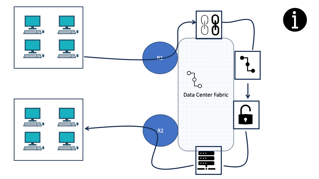
Some application flows need to pass through security or inspection functions before reaching their destination. Service insertion directs selected traffic through a required service, while Service Function Chaining defines a logical sequence of functions for a particular traffic class or service.

Building a reliable chain involves more than drawing a path through appliances. Engineers must consider service health, return-path behaviour, capacity, latency, failure handling and the policy requirements that determine which traffic must traverse each function.

Firewall Inspection Service sequence Failure handling
Section 06 · Service-Aware Networking

Service Insertion and Service Function Chaining

Application traffic does not always travel directly from source to destination. Some flows must pass through security, inspection or optimisation services before they reach their target. Service insertion steers selected traffic through these functions, while Service Function Chaining (SFC) defines an intended sequence of functions for a traffic class or service.

For example, traffic entering an enterprise application may need to pass through a firewall, an intrusion prevention system and a traffic monitor. The steering system must identify the relevant traffic, select the required service path and preserve the intended forwarding behaviour throughout the chain.

What is a service function chain?

Client Application request
→
Firewall Enforce security policy
→
Inspection Inspect eligible traffic
→
Monitor Observe traffic behaviour
→
Application Receive the request

This diagram illustrates one possible chain. A real deployment may use different functions, may bypass selected services for certain traffic classes, and must account for return traffic and the capabilities of the services and forwarding infrastructure.

Common service functions

Security
Firewall

Applies access-control policy to permit or deny traffic according to defined rules and connection state.

Threat detection
Intrusion prevention

Examines eligible traffic for suspicious patterns or known threats and applies configured prevention actions.

Application delivery
Proxy or gateway

Mediates selected application connections, potentially enforcing application policy or providing protocol-aware processing.

Visibility
Traffic monitoring

Collects or analyses traffic information for troubleshooting, performance measurement and operational visibility.

How service-aware steering works

From application policy to forwarding path
1. CLASSIFY Identify the traffic class and applicable policy. 2. SELECT Determine which service functions are required. 3. STEER Direct traffic to the selected service path. 4. PROCESS Allow each service to perform its intended function. 5. FORWARD Continue toward the destination after the required processing. 6. VERIFY Confirm delivery, service health and expected policy behaviour.

This is a conceptual workflow rather than a protocol-specific implementation. The exact sequence depends on the network architecture, steering mechanism and service-chain design.

Policy-based service selection

Not every application flow needs the same treatment. A steering policy can associate traffic classes with different service requirements. The classification method may use network-layer fields, transport-layer information, application identity or metadata supplied by a trusted policy system, depending on the platform.

Corporate application traffic

Send eligible traffic through firewall inspection before forwarding it to an internal application.

Guest network traffic

Apply a separate access policy and direct traffic through the appropriate security controls.

Sensitive data flows

Require additional inspection or monitoring where the policy and applicable privacy requirements permit it.

Low-risk internal flows

Use a shorter approved path when policy allows, avoiding unnecessary service processing and additional latency.

A shorter path is not automatically a better path

Bypassing a service can reduce latency and processing overhead, but it may also remove a required security or compliance control. Steering decisions must respect the intended service policy, not simply choose the route with the fewest hops.

Ways to implement service insertion

Network policy
Policy-based routing

Match selected traffic and direct it toward a service next hop or inspection path. The design must account for routing reachability, next-hop availability and return traffic.

Programmable forwarding
SDN and flow rules

Use controller-managed forwarding rules to steer supported traffic through selected service points, subject to device capabilities.

Service-chain architecture
Service Function Chaining

Define a logical sequence of service functions and use a compatible forwarding architecture to guide traffic through that sequence.

Application delivery
Proxy or load balancer

Insert an application-aware intermediary that can enforce policy, inspect supported protocols or select an appropriate backend.

Operational challenges to design for

  • Service availability: Define what happens if a required firewall or inspection service becomes unavailable. Fail-open and fail-closed behaviour have different security and availability consequences.
  • Return-path symmetry: Stateful services may require both directions of a connection to traverse the same service instance or a coordinated cluster.
  • Capacity and latency: Each service adds processing overhead and may become a bottleneck. Estimate aggregate throughput, connection scale and expected delay.
  • Loop prevention: Ensure that traffic cannot repeatedly re-enter the same service chain because of incorrect forwarding rules.
  • Encapsulation and MTU: If the architecture adds encapsulation, validate path MTU and account for the extra headers.
  • Policy consistency: Make sure changes to classification or chain definitions are reflected safely across the relevant devices.

Example: investigating an application delay

Scenario

Users report that an internal application has become slow. The network path includes a firewall, an inspection service and the application gateway.

Observed: Client → Firewall → Inspection → Gateway → Application Investigate: 1. Compare latency before and after each service. 2. Check service health, CPU and connection capacity. 3. Confirm that the flow matches the intended policy. 4. Verify forward and return paths. 5. Test any approved policy change in a controlled scope.

The aim is to identify which part of the chain contributes to the delay. Removing a service without confirming its security role is not a sound troubleshooting shortcut.

Service chaining versus ordinary routing

Ordinary routing generally selects a next hop toward a destination according to the routing table and associated policy. Service chaining adds another requirement: eligible traffic must visit specified functions before continuing toward its destination.

BGP can provide reachability to service networks or destinations, but BGP alone does not define a complete application service chain. Additional policy, forwarding rules or service-chain mechanisms are needed to enforce the required sequence.

Key takeaway

Service insertion makes traffic steering aware of the network services a flow must traverse. A successful design combines correct classification, a deliberate service sequence, reliable forwarding, health handling and verification that security and application requirements remain satisfied.

Network Insight · Interactive Lab 06

Service Insertion and Service Function Chaining

Steer application traffic through a defined sequence of security and visibility services before it reaches the destination.

Chain ready
01 / Service function chain
Stage 0 of 5
▦
Application Incoming traffic
→
⬡
Firewall Policy inspection
→
⌕
IPS Threat inspection
→
◉
Monitor Visibility / telemetry
→
◎
Destination Application service
Illustrative chain: application traffic is directed through selected service functions in sequence. A failed mandatory service can stop the flow.
02 / Chain telemetry
Current simulated flow
Stages completed0 / 5
Added delay0 ms
Flow outcomePending
Awaiting traffic

Select a chain profile and process the flow one stage at a time, or run the complete chain.

04 / Processing sequence
Waiting for flow
1
Classify trafficIdentify the application and applicable chain policy.
2
Insert service pathDetermine the required service functions and order.
3
Inspect at each serviceApply firewall, IPS and visibility processing.
4
Handle failure or threatContinue, bypass or stop according to the demonstration policy.
5
Deliver or blockRecord the final outcome for the application flow.
05 / Service event timeline
0 events
Chain initialized
Ready to process an application flow.
Engineering note: This is a conceptual service-function-chaining model. Real deployments can use service-function forwarders, overlays, metadata, policy classifiers and platform-specific steering mechanisms. Bypass, fail-open and fail-closed behaviour depends on service criticality and the configured operational policy; this lab uses a simplified mandatory-versus-optional control.
07 / Identity and Application Policy

Identity-Aware Traffic Steering

Traffic decisions can use more than IP addresses and ports. An application may also evaluate authenticated user identity, workload identity, roles and trusted policy signals to determine which resources or services a request is permitted to access.

This section connects application-level policy to traffic handling through a Node.js example. It also explains the boundary between choosing an application backend and changing the network forwarding path, plus the validation and enforcement needed to make identity-aware decisions secure.

Authentication Authorisation Node.js example Policy enforcement
Section 07 · Identity and Application Policy

Identity-Aware Traffic Steering

Traditional network policies commonly classify traffic using addresses, protocols, ports and other packet attributes. Modern application architectures can add another dimension: identity. An application may use authenticated user identity, workload identity or a trusted policy decision to determine which service, resource or application path a request is allowed to access.

Identity-aware steering connects application context to policy enforcement. For example, a request from an authorised employee might be directed to an internal application service, while a request without the required permissions is denied or sent through an additional verification step.

An important distinction

Identity-aware application routing is not automatically the same as network-layer path selection. An application gateway may choose a backend or reject a request without changing the underlying IP route. Network forwarding changes require a compatible network policy or steering mechanism.

From identity to an application decision

01 · AUTHENTICATE Establish identity Verify the user, workload or client through an appropriate identity system.
→
02 · AUTHORISE Evaluate permissions Check roles, claims and access policy for the requested resource.
→
03 · SELECT Choose the outcome Permit, deny, require another check or select an approved application service.
→
04 · VERIFY Enforce and log Apply the decision and record the outcome without exposing sensitive data.

What information can inform steering?

User context
Authenticated identity

A verified user identity or group membership can help determine whether a request is permitted to access a protected application.

Workload context
Service identity

A service-to-service request can be evaluated using the identity of the calling workload, rather than trusting its IP address alone.

Request context
Resource and operation

The requested resource and operation can determine which application handler, backend or access policy should apply.

Risk and policy
Trusted policy signals

A trusted access system may provide policy outcomes based on approved context, subject to the organisation's security design.

Example: a Node.js application gateway

Consider a Node.js service that receives an authenticated request and determines which application endpoint the caller may use. The application should verify the authentication evidence and then make an explicit authorisation decision. It should not treat a client-supplied role, username or HTTP header as proof of identity.

Illustrative policy logic
Incoming request | v Verify authentication token | v Check token issuer, audience, expiry and signature | v Evaluate required permission | +---- Not authorised ----> Reject request | +---- Authorised --------> Select permitted service | v Log outcome

The diagram describes a control flow rather than a complete, production-ready authentication implementation. Token verification must use a trusted identity configuration and suitable libraries.

Illustrative Node.js decision function

The following small example demonstrates the policy decision after authentication has already been performed by a trusted middleware or identity integration. It is not a substitute for verifying credentials.

function selectApplicationService(principal) { if (!principal || !Array.isArray(principal.roles)) { return { allowed: false, reason: "missing_identity" }; } if (principal.roles.includes("operations")) { return { allowed: true, service: "operations-api" }; } if (principal.roles.includes("employee")) { return { allowed: true, service: "employee-portal" }; } return { allowed: false, reason: "insufficient_permission" }; }

In this example, the function receives a principal object created by trusted authentication middleware. It checks an allowlisted set of roles and returns a service selection or denial. A real application must also enforce the returned decision, validate the principal's provenance and apply resource-specific authorisation.

Do not confuse selection with enforcement

Returning a service name does not itself secure a request. The application must ensure that the selected service is actually used, that unauthorised callers cannot bypass the gateway and that each downstream service applies its own required access controls.

Application steering versus network steering

Application layer
Select a backend or endpoint

A gateway or application can direct a permitted request to a service, API version or backend pool. The underlying network still forwards packets according to its own routing and forwarding rules.

Network layer
Select a forwarding path

A network policy, SDN controller or compatible forwarding system changes how eligible packets traverse the network. It needs an appropriate way to map trusted identity or policy context to traffic.

How identity can connect to network policy

In a larger architecture, an identity-aware application or policy service may communicate a decision to an enforcement point. Depending on the environment, enforcement could occur at an API gateway, service mesh proxy, firewall, network access control system or programmable network controller.

  • Establish a trusted mapping: Define how an authenticated identity or workload maps to a policy and the traffic it governs.
  • Use an appropriate enforcement point: Apply the decision where the relevant request or traffic can actually be controlled.
  • Limit policy scope: Avoid broad network changes when an application-level allow or deny decision is sufficient.
  • Handle policy changes: Consider token expiry, revoked permissions, stale rules and the time needed to distribute updates.
  • Maintain observability: Correlate application decisions with network events using suitable identifiers while minimising sensitive information in logs.

Security and operational considerations

Token validation

Validate signature, issuer, audience, expiry and other required claims. Never trust decoded token contents without verifying the token.

Least privilege

Grant only the permissions required for the specific resource and operation. A general role should not automatically imply unrestricted access.

Trusted headers

Remove or overwrite externally supplied identity headers at a trusted gateway before passing identity context to downstream services.

Fail-safe behaviour

Define what happens when the identity provider or policy service is unavailable. Avoid silently treating an unknown identity as authorised.

When is identity-aware steering useful?

  • Multi-tenant platforms: Direct authorised requests to the correct tenant service while preventing cross-tenant access.
  • Internal APIs: Apply different permissions to operations, users and service identities.
  • Zero-trust architectures: Make access decisions based on verified identity and policy rather than relying on network location as the sole trust signal.
  • Controlled application migration: Direct eligible requests to an approved service version or backend after authorisation.
Key takeaway

Identity-aware traffic steering brings authenticated identity and application policy into request handling. Node.js can demonstrate application-level service selection, while broader network steering requires a trusted integration between identity, policy and the appropriate forwarding enforcement point.

Network Insight · Interactive Lab 07

Identity-Aware Traffic Steering

Use identity, device posture and application context to determine which services a user can reach and how their traffic is handled.

Policy ready
01 / Identity-to-application path
Stage 0 of 5
♙
Employee · Standard access Identity awaiting evaluation
ROLE: EMPLOYEE DEVICE: TRUSTED
♙
User / Identity Role and group
→
◇
Access policy Identity + context
→
⇢
Traffic steering Choose permitted path
→
▦
Application Allow or deny access
Illustrative access path. Identity-aware systems can enforce policy at gateways, proxies, application access brokers or other enforcement points.
Checks completed0 / 5
Policy outcomePending
Selected route—
Awaiting access request

Choose an identity, application and device posture. Then evaluate the request to see how policy changes the traffic path.

03 / Decision sequence
Waiting for request
1
Identify the userResolve the identity and associated role or group.
2
Evaluate device and contextCheck device trust, MFA, network and sign-in risk.
3
Match application policyCompare the requested application with role permissions.
4
Select enforcement pathChoose a permitted route, step-up action or denial.
5
Enforce and recordAllow or deny the request and record the decision.
04 / Policy event log
0 events
Policy engine ready
Waiting for an access request.
Engineering note: This is a teaching simulation, not a production identity provider or security policy engine. The role permissions and access outcomes are illustrative. Real deployments require explicit authorization rules, strong identity verification, device posture signals, least-privilege design, and carefully defined handling of risk and authentication failures.
Network Insight · Key Takeaways

Conclusion: From Traffic Forwarding to Intent-Based Steering

Application traffic steering is about more than finding a route from one network to another. It is about making an informed forwarding decision based on the application, the user, the current network conditions, security requirements and the destination service.

Traditional routing provides the underlying reachability, while technologies such as policy-based routing, SD-WAN, load balancing, software-defined networking and service function chaining add different ways to influence how traffic travels. Identity-aware policies extend this approach by considering who is requesting access, whether the device is trusted and which application the user is permitted to reach.

The central engineering principle

Classify the traffic, evaluate the relevant policy, select an appropriate path, and verify the outcome. Effective steering must balance application performance, availability, security and operational simplicity rather than optimise one factor in isolation.

01
Classify Identify the application, traffic flow, user or device context.
02
Evaluate Apply routing policy, access rules, service requirements and performance signals.
03
Steer Choose an eligible route, network path, service chain or application endpoint.
04
Verify Check reachability, application health, policy enforcement and observed performance.
Connect the concepts · BGP

Where does BGP fit into application traffic steering?

Border Gateway Protocol (BGP) supplies routing information and path-selection mechanisms that can support traffic-engineering objectives. Local preference can influence outbound path selection within an autonomous system, AS-path prepending can influence how some external networks compare routes, and carefully designed more-specific advertisements can affect inbound traffic patterns. These mechanisms have different scopes and limitations: they do not replace application-aware policy, and their effect depends on routing configuration and the behaviour of other networks.

BGP Best-Path Selection Local Preference AS-Path Prepending Route Advertisement Traffic Engineering

In a real deployment, the best design is rarely a single technology. Routing, application delivery, security controls and identity policy often work together. The challenge is to define clear responsibilities between these layers, avoid conflicting policies, and ensure that a steering decision remains observable and supportable when conditions change.

Final takeaway: Good traffic steering is deliberate, measurable and policy-driven. The goal is not simply to move packets along a different path; it is to deliver the required application experience through a path that meets the organisation's performance, availability and security objectives.

```
☕
Support Network Insight
Help support independent engineering guides, interactive networking tools, and future learning labs.
Support Network Insight ```
NFV

NFV Use Cases

NFV Use Cases

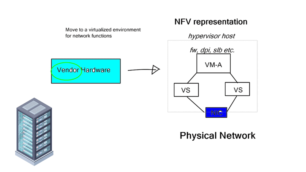
Network Function Virtualization (NFV) has emerged as a transformative technology in networking. By decoupling network functions from dedicated hardware and implementing them in software, NFV offers remarkable flexibility, scalability, and cost-efficiency. This blog post will explore the diverse range of NFV use cases and how this technology is revolutionizing various industries.

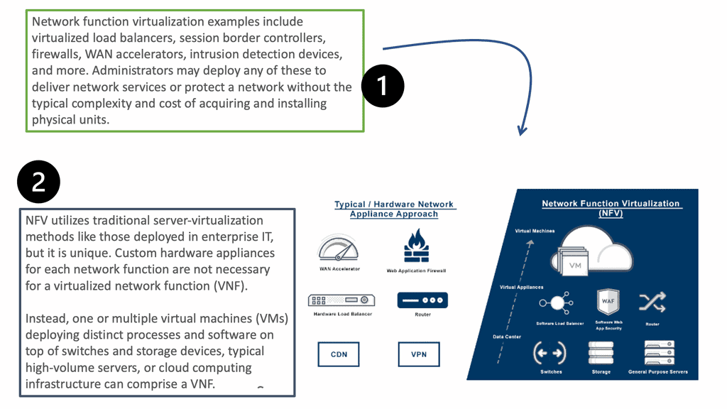
NFV allows the virtualization of various network appliances such as firewalls, load balancers, and routers. This consolidation of functions into software-based instances simplifies network management, reduces hardware complexity, and enables efficient resource allocation.

NFV in Telecommunications: With the rapid expansion of mobile networks and the increasing demand for bandwidth, telecommunications companies are embracing NFV to enhance their infrastructure. By virtualizing network functions such as firewalls, load balancers, and session border controllers, telecom operators can achieve cost savings, simplified management, and faster service deployment. NFV also enables dynamic scaling of resources, ensuring optimal network performance even during peak usage periods.

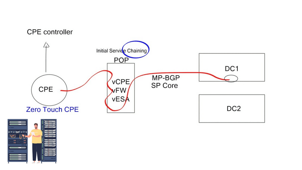
NFV in Cloud Computing: Cloud service providers leverage NFV to deliver scalable and on-demand network services to their customers. By virtualizing functions like virtual routing, switching, and firewalls, cloud providers can offer flexible and customizable network configurations to meet diverse client requirements. NFV also enables rapid service chaining, allowing for the seamless integration of different network functions to create complex service offerings.

NFV in the Internet of Things (IoT): The proliferation of IoT devices brings forth new challenges in terms of managing and securing the massive amounts of data generated. NFV plays a crucial role in IoT deployments by providing virtualized security services that can be dynamically allocated based on the changing demands of IoT networks. Additionally, NFV enables efficient data processing and analysis at the edge, reducing latency and improving overall system performance.

NFV in the Healthcare Industry: The healthcare sector is embracing NFV to enhance patient care, optimize resource utilization, and improve operational efficiency. By virtualizing functions like patient monitoring systems, electronic health records, and secure communications, healthcare providers can streamline workflows, reduce costs, and ensure data privacy. NFV also enables telemedicine services, facilitating remote consultations and enhancing access to healthcare in underserved areas.

The use cases of NFV span across various industries, showcasing its versatility and transformative potential. From telecommunications to cloud computing, IoT, and healthcare, NFV's ability to virtualize network functions offers numerous benefits such as cost savings, flexibility, and scalability. As technology continues to evolve, NFV will undoubtedly play a pivotal role in shaping the future of networking, enabling innovative solutions to meet the ever-growing demands of the digital era.

NFV Use Case

**Introduction to Network Function Virtualization (NFV)**

In the ever-evolving landscape of technology, Network Function Virtualization (NFV) has emerged as a groundbreaking innovation. This transformative approach to network architecture promises to revolutionize how service providers create and deliver network services. By decoupling network functions from proprietary hardware appliances, NFV offers unprecedented flexibility and scalability. But what exactly is NFV, and why does it hold such promise for the future of networking?

**The Architecture Behind NFV**

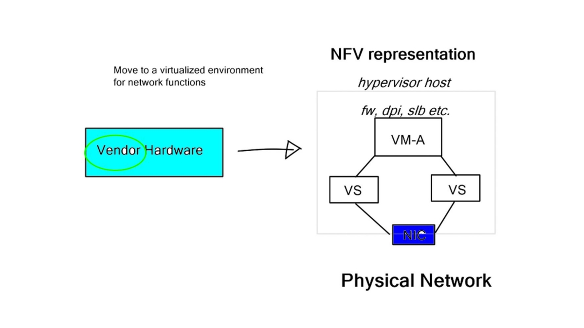
At its core, NFV is about transforming network functions into software applications that can run on standard servers. This shift allows for the virtualization of functions such as firewalls, load balancers, and routers, which were traditionally tied to specific hardware. The architecture relies on a combination of virtual machines, hypervisors, and cloud computing to create a dynamic and efficient network environment. By using commercial off-the-shelf hardware, service providers can reduce costs and increase agility in deploying new services.

**Benefits of Adopting NFV**

The adoption of NFV brings a myriad of benefits to both service providers and end-users. For providers, it means a significant reduction in capital and operational expenditures. The flexibility to deploy network functions as software applications enables faster service innovation and deployment. For end-users, NFV translates to improved service delivery, with enhanced reliability and performance. Moreover, the scalability of NFV allows for better management of network resources, adapting quickly to varying demands.

**Challenges in Implementing NFV**

Despite its advantages, implementing NFV is not without challenges. One of the primary concerns is the integration of NFV with existing network infrastructures. As providers transition from hardware-based solutions to virtualized environments, they must ensure compatibility and interoperability. Additionally, security remains a critical issue, as virtualization introduces new vulnerabilities. Addressing these challenges requires a robust strategy and collaboration between industry players to establish standards and best practices.

**The Future of NFV**

Looking ahead, NFV is poised to play a crucial role in the advancement of 5G networks and the Internet of Things (IoT). As the demand for high-speed, low-latency services grows, NFV’s ability to deliver flexible, scalable solutions will be invaluable. The technology’s potential to support innovative services, such as network slicing and edge computing, positions it as a key driver of future network evolution. As NFV matures, we can expect to see even greater integration with emerging technologies, further reshaping the networking landscape.

Network Function Virtualisation (NFV)

At its core, NFV decouples network functions such as firewalls, load balancers, and routers from proprietary hardware appliances, allowing them to run as software on a range of hardware. This shift not only reduces the reliance on specialized hardware but also enhances the flexibility and scalability of networks. By leveraging standard IT virtualization technology, NFV enables network operators to deploy new services with greater speed and efficiency.

It could be argued that Network Function Virtualization (NFV) builds on some of the basic and now salient concepts of Software Defined Networking (SDN). Separation of control and data planes, logical centralization, controllers, network virtualization (logical overlays), application awareness, and application intent control are all trending toward running on commodity (Commercial Off-The-Shelf (COTS)) hardware platforms.

With NFV, these concepts are expanded with new methods supporting service element interconnection, such as Service Function Chaining (SFC), and new management techniques for coping with its dynamic, elastic capabilities.

**Network Service and Service Function**

A: – The concept of a network service refers to any computational service that possesses a network component. Some functions can discriminate between individual network flows or manipulate them in other ways. According to the IETF SFC Architecture document, an operator’s offering is delivered using one or more service functions.

B: – The IETF document defines a service function as a function responsible for treating received packets in a specific manner: “A function responsible for treating received packets in a particular manner.” A network element that provides a service function, whether virtual or traditional, highly integrated, may also offer multiple service functions, so we would refer to it as a “composite.”

NFV is not complicated

C: – Network functions virtualization (NFV) is not a complicated concept. The term refers to deploying hardware functions as software instead of hardware. Most commonly, virtual machines (VMs) serve as routers, firewalls, load balancers, intrusion detection and prevention systems (IDS/IPS), virtual private networks (VPNs), application firewalls, and other functions.

D: – A monolithic piece of hardware may cost tens of thousands of dollars and may have thousands of lines of code, and with NFV, it can be broken down into N pieces of software- namely, virtual appliances. A smaller device makes it easier to manage from the perspective of a single device.

A Key Point: Network Virtualization:

In network virtualization, endpoints are grouped logically on a network. As a result of this abstraction, VMs (and other assets) appear, behave, and can be managed as if they were all located on the same physical segment of the network. Even though it is an old technology, it is essential in virtual environments, where assets are created and moved without much regard for location. Automation and management tools have been designed specifically for scalable and elastic virtualized data centers and clouds.

NFV Use Cases

1. Telecommunications:

NFV has revolutionized the telecommunications sector by enabling the virtualization of crucial network functions. Service providers can now deploy virtualized network functions (VNFs) such as routers, firewalls, and load balancers, reducing the reliance on dedicated hardware. This allows for dynamic scaling, faster service deployment, and increased operational efficiency.

2. Cloud Computing:

NFV is playing a pivotal role in the evolution of cloud computing. By virtualizing network functions, NFV enables the creation of software-defined networking (SDN) architectures, which offer greater agility and flexibility in managing network resources. This allows cloud service providers to quickly adapt to changing demands, optimize resource allocation, and deliver services with enhanced performance and reliability.

3. Internet of Things (IoT):

The proliferation of IoT devices has created new challenges for network infrastructure. NFV has emerged as a solution to meet the dynamic demands of IoT deployments. By virtualizing network functions, NFV enables the efficient management and orchestration of network resources to support the massive scale and diverse requirements of IoT applications. This ensures seamless connectivity, efficient data processing, and improved overall performance.

4. Enterprise Networking:

NFV significantly benefits enterprise networking by simplifying network management and reducing costs. With NFV, enterprises can deploy virtualized network functions to replace traditional hardware appliances, reducing hardware and maintenance costs. This enables enterprises to rapidly deploy new services, scale their networks as per demand, and improve overall network performance and security.

5. Service Chaining:

NFV enables service chaining, which refers to the sequential routing of network traffic through a series of virtualized network functions. Service chaining allows for the creation of complex network service workflows, enabling the delivery of advanced services such as network security, traffic optimization, and deep packet inspection. NFV’s ability to dynamically chain and orchestrate virtualized network functions opens up new possibilities for service providers to deliver innovative and personalized services to their customers.

Network Functions Virtualization

Within NFV, Layer 4 through 7 services such as load balancing and firewalling are virtualized. Virtualization enables certain types of network appliances to be easily deployed wherever needed by converting them into virtual machines. Inefficiencies caused by virtualization led to the creation of NFV. Virtualization has been discussed primarily for its benefits but has also caused many problems.

Data center traffic was routed to and from network appliances at the network’s edge. There is a problem for fixed appliances since VMs are springing up and moving around. Virtualizing functions like firewalls can be easily “spun up” and placed where needed, just like virtual machines.

Virtual Networks with VXLAN:

Virtual machines supporting applications or services require physical switching and routing to connect to the data center or cloud and clients over a WAN link or the Internet. Data center networks must be secure in addition to load balancing and security. As traffic leaves the VM, it encounters a virtual switch (hypervisor), and then a physical switch at the top or end of the rack. The physical network cannot cope with the rapidly shifting state of virtual machines once traffic leaves the hypervisor.

VXLAN multicast mode
Diagram: VXLAN multicast mode

The issue can be circumvented by creating a logical network of VMs that spans the physical networks. Encapsulation is used in VXLAN, as in most other network virtualization forms. In contrast to simple VLANs, which can create only 4096 logical networks per physical network, VXLAN can create about 16 million logical networks per physical network. That scale is necessary for a large data center or cloud.

A shift from hardware-centric:

NFV, at its core, is the virtualization of network functions traditionally performed by dedicated hardware appliances. It enables the decoupling of network functions from specialized hardware, allowing them to be run as software on general-purpose servers. This shift from hardware-centric to software-centric network infrastructure brings immense flexibility, agility, and resource optimization advantages.

SDN and NFV

While Software Defined Networking (SDN) and Network Function Virtualization (NFV) are used in the same context, they satisfy separate functions in the network. NFV is used to program network functions, like network overlays, QoS, VPNs, etc., enabling a series of SDN NFV use cases. SDN is used to program the network flows. They have entirely different heritages. SDN was born in academic labs and found roots in the significant hyper-scale data center topologies of Google, Amazon, and Microsoft.

Its use case moves from the internal data center to the service provider and mobile networks. NFV, on the other hand, was pushed by service providers in 20012-2013, and work is driven out of the European Telecommunications Standard Institute (ETSI) working group. The ETSI has proposed an NFV reference architecture, several white papers, and technology leaflets. 

You may find the following valuable post for pre-information:

  1. Ansible Tower
  2. What is OpenFlow
  3. LISP Protocol
  4. Open Networking
  5. OpenFlow Protocol
  6. What is BGP protocol in Networking
  7. Removing State From Network Functions

NFV Use Cases

Over the past few years, it has become increasingly popular for companies operating within different industrial and commercial sectors to use network function virtualization (NFV) to solve multiple networking challenges. With the expansion of the Internet of Things (IoT) and advances in network communications technologies, along with the growing demand for ever more advanced services, network function virtualization is allowing enterprises to design, provide, and ease into much more advanced services and operations as well as reduce outgoings through cost savings.

Highlighting NFV

Network Function Virtualization (NFV) is a network architecture concept that uses software-defined networking (SDN) principles to virtualize entire classes of network node functions into building blocks that can be connected, composed, and reconfigured to create communication services. This virtualization approach to developing a programmable network layer is essential to realizing a Software Defined Network (SDN).

NFV enables the network administrator to rapidly create, deploy, and configure network services across data centers and remote locations, eliminating the need to deploy and maintain dedicated hardware for each service. In addition, by virtualizing the network functions, the network administrator can use a single instance of the service across the entire network, reducing complexity and management overhead.

NFV Benefits

The main benefit of NFV is that it simplifies network management, allowing the network administrator to create, deploy, and configure services as needed quickly.  It also reduces costs associated with managing multiple instances of the same service. Additionally, NFV enables the network administrator to quickly deploy new services, allowing for rapid deployment and testing of new network services.

In addition to these benefits, NFV also provides flexibility and scalability. By leveraging virtualization, the network administrator can quickly scale the network up or down as needed without purchasing additional hardware. Additionally, NFV allows for more efficient use of resources, eliminating the need to buy dedicated hardware for each service.

NFV use cases
Diagram: NFV. The source is AVI.

NFV Advanced

Network function virtualization (NFV) denotes a significant transformation for telecommunications/service provider networks, pushed by reducing cost, increasing flexibility, and providing personalized services. NFV leverages cloud computing principles to change how NFs such as gateways and middleboxes are offered. Unlike today’s tight coupling between the NF software and dedicated hardware, the loosely coupled software and hardware in NFV can relieve the upgrade cost and increase innovation flexibility.

**SDN NFV Use Cases: ASIC and Intel x86 Processor**

To understand network function virtualization, consider the inside of proprietary network devices and standard servers. The inside of a network device looks similar to that of a standard server. They have several components, including Flash, PCI bus, RAM, etc. Apart from the number of physical ports, the architecture is very similar. The ASIC (application-specific integrated circuit) is not as important as vendors would like you to believe.

When buying a networking device, you are not paying for the hardware—the hardware is cheap—but for the software and maintenance costs. Hardware is a minor component of the total price. Why can’t you run network services on Intel x86? Why is there a need to run these services on vendor-proprietary software? x86 general-purpose OSs can perform just as well as some routers with dedicated silicon.

SDN NFV use cases
Diagram: SDN NFV use cases

Network Function Virtualization Architecture

The concept of NFV is simple: Let’s deploy network services in VM format on generic, non-proprietary hardware. NFV increases network agility by deploying services in seconds, not weeks. The time-to-deployment is quicker, enabling the introduction of new concepts and products in line with the business deployment speeds needed for today’s networks.

In addition, NFV reduces the number of redundant devices. For example, why have two firewall devices on active / standby when you can insert or replace a failed firewall in seconds with NFV?  It also simplifies the network and reduces the shared state in network components.

A shared state is always bad for a network, and too much device complexity leads to “holy cows.” A holy cow is a network device ingrained so much in the network with obsolete and old configurations it cannot be moved quickly or cheaply (everything can be moved at a cost).

NFV use cases

However, not everything can be expressed in software. You can’t replace a Terabit switch with an Intel CPU. Replacing a top-end Cisco GSR or CSR with an Intel x86 server may be cheaper, but it is far from practical functionally. There will always be a requirement for hardware-based forwarding, which will likely never change. But if your existing hardware uses Intel’s x86 forwarding, there is no reason it can’t run on generic hardware.

Possible SDN NFV use cases with network function for NFV include Firewalls with stateful inspection firewall capabilities, Deep Packet Inspection (DPI) devices, Intrusion Detection Systems, SP CE and PE devices, and Server Load Balancers. DPI is never usually done in hardware, so why can’t we put it on an x86 server?

Load balancing can be scaled out among many virtual devices in a pay-as-you-grow model, making it an accepted NFV candidate. There is no need to put 20 IP addresses on a load balancer when you can quickly scale 20 independent load balancing instances in NFV format.

Network Function Virtualization Architecture
Diagram: Network Function Virtualization Architecture

 Control plane functionality

While the relevant use cases of NFV continue to evolve, an immediate and widely accepted use case would be with control plane functionality. Control plane functions don’t require intensive hardware-based forwarding functions. Instead, they provide reachability and control information for end-to-end communication.

Example Technology: BGP Route Reflection

**What is BGP Route Reflection?**

At its core, BGP route reflection is a method used to optimize the dissemination of routing information within a network. Traditionally, BGP required a full mesh of internal BGP (iBGP) peers, which could become unwieldy as networks grew. Route reflection provides a solution to this scalability issue by allowing a BGP router, known as a route reflector, to propagate routes to other BGP routers without needing a direct link.

**How Route Reflection Works**

Route reflection simplifies network architecture by introducing route reflectors and clients. The route reflector acts as a central point that receives routing updates and then reflects, or disseminates, these updates to its clients. This structure reduces the number of connections required, improving network efficiency and manageability. By implementing route reflection, network operators can maintain fewer connections and still ensure optimal route dissemination, making it a popular choice in large-scale network environments.

**The Advantages of Route Reflection**

There are several key advantages to using route reflection in BGP. First and foremost, it significantly reduces the complexity of managing network connections. By minimizing the number of iBGP peering sessions, route reflection alleviates the administrative burden and lowers the potential for configuration errors. Additionally, route reflection can lead to improved network performance by streamlining the path selection process, ensuring that data takes the most efficient route possible.

**Challenges and Considerations**

While route reflection offers many benefits, it is not without its challenges. One of the primary concerns is the potential for suboptimal routing. Because route reflectors may not have a complete view of the network, there is a risk that the path chosen might not be the most efficient. Network operators need to carefully design their route reflection topology and consider redundancy to mitigate these risks. Additionally, understanding the underlying BGP policies and configurations is crucial to avoid unforeseen routing issues.


BGP RR and LISP Mapping Database

For example, take the case of a BGP Route-Reflector (RR) or LISP Mapping Database. An RR does not participate in data plane forwarding. It is usually designed in a redundant route reflector cluster for control plane services, reflecting routes from one node to another. It is not in the data transit path.

We have used proprietary vendor hardware as route reflectors for ages as they had the best BGP stack. But buying a high-end Cisco or Juniper device just to run RR control plane services wastes money and hardware resources. Why buy a router with suitable forwarding hardware when you only need the control plane software element? 

LISP mapping databases

LISP Mapping Databases are commonly deployed on x86, not a dedicated routing appliance. This is how the lispers.net open ecosystem mapping server is deployed. All routers needed for control plane services can be put in a VM. Control plane functionality is not the only one for NFV use cases. Service providers are also implementing NFV for virtual PE and virtual CE devices.

They offer per-customer use cases by building a unique service chain for each customer. Some providers want to allow customers to build their own service chains. This allows you to quickly create new services and test service adoption rates to determine if anyone is buying the product—a great way to test new services.

LISP networking
Diagram: LISP Networking. Source is Cisco

Network Function Virtualization performance

There are three elements relating to performance – management, control, and data plane. Management and control plane performance is not as critical as the data plane. As long as you get decent protocol convergence timers, it should be good enough. But generally speaking, they are not as crucial as data plane forwarding, which is critical for performance.

The performance you get out of the box with an x86 device isn’t outstanding; maybe 1 or 2 GiG of forwarding performance. If you do something simple like switching Layer 2 packets, the performance will increase to 2 or 3 gigs per core. Unfortunately, this is considerably less than what the actual hardware can do. The hardware can push 50 to 100GiG through a mid-range server. Why is out-of-the-box performance so bad?

TCP stack and Linux kernel

The problem lies with the TCP stack and Linux Kernel. The Linux Kernel was never designed for high-speed packet forwarding. It could offer a better data plane but an excellent control plane function. To improve performance, you may need multi-core processing. Sometimes, the forwarding path taken by the virtual switch is so long that it kills performance.

Significantly, when the encapsulation and decapsulation process of tunneling is involved, in the past, when you started to use Open vswitch (OVS) ( what is OVS ) with GRE tunneling – VPNoverview performance fell drastically.

They never had this problem with VLANS because they used a different code path. With the latest version of OVS, performance is not an issue. On the contrary, it’s faster than most of its alternatives, such as the Linux Bridge.

The performance has increased due to the changes in architecture for multithreading, megaflows, and additional classification improvements. It can be optimized further with Intel DPDK. DPDK is a set of enhanced libraries and drivers that enable kernel bypass, gaining impressive performance. Performance may also be achieved by moving the hypervisor out of the picture with SR-IOV.

SR-IOV slices a single physical NIC into multiple virtual NICs, and then you connect the VM to one of the virtual NICs. You are allowing the VM to work with the hardware directly.

Summary: NFV Use Cases

Section 1: NFV in Telecommunications

NFV has significantly impacted the telecommunications industry by enabling service providers to virtualize network functions, such as routing, firewalls, and load balancing. This virtualization allows for increased flexibility, scalability, and cost-effectiveness in managing network infrastructure.

Section 2: NFV in Healthcare

The healthcare sector has seen the integration of NFV to optimize network performance and security. By virtualizing functions like data storage, security protocols, and patient monitoring systems, healthcare providers can streamline operations, improve patient care, and enhance data privacy.

Section 3: NFV in Banking and Finance

In the banking and finance industry, NFV offers many benefits, including enhanced network security, improved transaction speeds, and efficient data management. Virtualizing functions like fraud detection, virtual private networks (VPNs), and disaster recovery systems enable financial institutions to stay competitive in a rapidly evolving digital landscape.

Section 4: NFV in the Internet of Things (IoT)

The proliferation of IoT devices necessitates robust network infrastructure to handle the massive influx of data. NFV optimizes IoT networks by providing virtualized functions like data analytics, security, and edge computing. This enables efficient data processing, reduced latency, and improved scalability in IoT deployments.