network traffic engineering

Network Traffic Engineering

Network Insight · Engineering Guide

Network Traffic Engineering: Optimising Paths, Performance and Capacity

Network traffic engineering is the practice of analysing, influencing and controlling how traffic moves through a network to meet defined performance, capacity, availability and policy objectives. Rather than relying exclusively on the paths selected by conventional routing, engineers can introduce additional controls to make better use of available network resources.

A routing table may identify a valid path to a destination, but that path is not necessarily the best choice for every traffic flow. A heavily utilised link, increasing latency, packet loss or an application with strict service requirements can make an alternative path more appropriate. Traffic engineering provides the methods to understand these conditions and influence forwarding decisions where the network design permits.

The central engineering question

How can we move the right traffic across the right path, at the right time, while respecting routing policy, available capacity, resilience and security requirements?

01

Measure the network

Monitor bandwidth utilisation, latency, jitter, packet loss and link health to identify congestion, performance changes and unused capacity.

02

Control traffic behaviour

Apply routing metrics, QoS policies, load balancing or explicit paths to influence how different traffic classes use network resources.

03

Choose suitable paths

Use the capabilities of technologies such as OSPF, IS-IS, BGP, MPLS Traffic Engineering and SDN to meet defined forwarding objectives.

04

Validate the outcome

Confirm that the selected path improves the intended metric without creating new bottlenecks or undermining redundancy and policy.

These techniques operate at different layers and solve different problems. QoS manages the treatment of traffic; routing protocols determine reachability and route preference; MPLS Traffic Engineering can establish constrained label-switched paths; and SDN can provide centralised visibility and programmable forwarding. Effective designs combine these capabilities where they add measurable value.

Topics explored in this guide
Congestion Management QoS and Bandwidth OSPF and IS-IS BGP Traffic Engineering MPLS RSVP-TE SDN and OpenFlow Cloud Networking WAN Optimisation
Network Insight · Traffic Engineering Guide

Network Traffic Engineering: Optimising Paths, Performance and Capacity

Network traffic engineering is the practice of measuring network behaviour and influencing how traffic uses available paths, links and services. It helps network engineers address congestion, make better use of capacity, improve application performance and design for failure.

From QoS and routing policy to MPLS traffic engineering, SDN, cloud networking and resilient WANs, this guide explores the mechanisms that shape traffic flow—and the important differences between selecting a route, managing a queue and measuring real application performance.

Traffic Measurement Routing & ECMP MPLS & SDN Cloud Networking WAN Resilience Interactive Lab
Section 01 · Observe Before Optimising

Traffic Measurement, Congestion and Quality of Service

Effective traffic engineering starts with evidence. Before changing routing policies, adjusting link costs or introducing explicit paths, engineers need to understand how traffic behaves, where congestion develops and which applications are affected. Measurement provides the foundation for making informed decisions rather than simply moving traffic from one link to another.

A network can have complete reachability and still deliver poor application performance. Routing protocols may select valid paths while a critical interface is saturated, queues are filling, packets are being discarded or delay-sensitive traffic is competing with large data transfers. Traffic engineering connects operational measurements with decisions about capacity, forwarding and traffic treatment.

1.1 The measurements that matter

No single metric explains every performance problem. Engineers combine interface statistics, active probes, flow records, queue counters and application telemetry to establish a more complete picture of network behaviour.

Bandwidth utilisation Shows how much of a link's available capacity is being consumed. Sustained high utilisation can indicate a bottleneck.
Latency Measures how long traffic takes to travel between measurement points. High delay can affect interactive applications.
Jitter Describes variation in packet delay. It matters particularly to real-time voice, video and other timing-sensitive traffic.
Packet loss Identifies packets that fail to reach the observation point. Congestion is one possible cause, but not the only one.
Queue behaviour Queue depth, drops and scheduling statistics help reveal contention at network interfaces.
Flow distribution Shows which conversations, applications or traffic classes consume capacity and how flows are distributed across paths.
Engineering principle: measure the path, not just the interface

A link may show acceptable average utilisation while users experience intermittent delay or loss. Correlate interface counters with end-to-end measurements, queue statistics and application symptoms before deciding where to intervene.

1.2 How congestion develops

Congestion occurs when traffic demands exceed the capacity available at a particular point, either temporarily or for a sustained period. Packets may accumulate in queues, increasing delay. When buffers fill, packets are dropped. Transport protocols may then retransmit data or reduce their sending rate, potentially reducing useful throughput further.

Congestion is not always caused by insufficient total network capacity. Traffic may be unevenly distributed, a preferred route may become overloaded, or several high-volume flows may converge on the same interface. A redundant path can remain underused even while another path is congested.

Observed symptom Possible explanation Useful investigation
High utilisation over time Demand is approaching or exceeding available capacity. Review interface rates, traffic trends and capacity forecasts.
Latency rises during busy periods Packets may be waiting in queues along the path. Compare latency with utilisation and queue statistics.
Loss on a particular interface Queue drops, physical errors, policing or another forwarding issue. Inspect drop counters, error counters and policy statistics.
One path is busy while another is idle Routing policy or flow-hashing behaviour may limit distribution. Check route selection, ECMP eligibility and per-flow traffic patterns.

1.3 Quality of Service: managing competing traffic

Quality of Service (QoS) provides mechanisms for classifying traffic and applying different forwarding treatments. It does not create additional bandwidth. Instead, it helps determine how available resources are shared when traffic competes for them.

A typical QoS design classifies packets into traffic classes, marks them where appropriate, and applies queuing, scheduling, shaping or policing policies at relevant points in the network. The design must be consistent across the intended path if the required treatment is to be maintained end to end.

Classify Identify traffic using defined rules.
Mark Apply an agreed traffic-class marking.
Queue and schedule Allocate transmission opportunities.
Verify Measure drops, delay and outcomes.

Several mechanisms are frequently used together, but they serve different purposes:

  • Classification and marking: identify traffic and communicate its intended treatment, commonly using fields such as DSCP.
  • Queuing and scheduling: control how packets from different classes share an interface during contention.
  • Traffic shaping: smooths or buffers traffic to enforce a configured transmission rate over time.
  • Policing: checks traffic against a rate or burst profile and may drop or remark packets that exceed it.
  • Admission and capacity control: helps prevent the network from accepting more traffic than the intended service can support.

For example, a voice class may receive low-latency treatment while bulk file transfers use remaining capacity. The voice queue still needs appropriate rate limits and capacity planning: an incorrectly configured priority queue can starve other traffic, and QoS cannot overcome a sustained shortage of physical bandwidth.

1.4 From monitoring to traffic engineering

Measurement and QoS are closely related to traffic engineering, but they are not the same thing. QoS primarily controls how packets are treated at forwarding points. Traffic engineering can go further by influencing which paths traffic uses, how demand is distributed across the topology, and whether additional capacity or protection paths are required.

If monitoring identifies a congested link, the appropriate response depends on the cause. Engineers might tune routing metrics, adjust traffic distribution, use policy-based routing, establish an MPLS Traffic Engineering path, or apply SDN-based control. If the problem is a physical fault or a queue configuration error, changing the route alone may not solve it.

Section takeaway

Reliable traffic engineering follows a measurement-led cycle: observe performance, identify the bottleneck, choose an intervention that matches the problem, and verify the result. These measurements become the evidence base for the routing and path-selection techniques explored in the next section.

Interactive lab · 01

Traffic Measurement & QoS Workbench

Change offered traffic, available capacity and queueing policy. Run the simulation to compare a simplified traffic-engineering outcome.

1. Traffic and capacity

120 Mbps
Total traffic arriving at the link.
100 Mbps
Maximum modelled service rate.
30%
Traffic marked as critical for this illustrative model.

2. Select a QoS policy

FIFO serves packets in arrival order. It does not prioritise critical traffic.
Ready. Adjust the inputs, then run the simulation.

Simulation results

Within capacity
Link utilisation
120%
Delivered throughput
100 Mbps
Modelled delay
— ms
Estimated loss / excess
16.7%
Offered load vs link capacity 120 / 100 Mbps
Offered traffic exceeds the configured link capacity.
1. ClassifyIdentify critical traffic
2. QueueApply selected policy
3. ScheduleAllocate service capacity
4. ForwardDeliver within capacity
The offered load exceeds link capacity. QoS can influence which traffic is served first, but it cannot create additional bandwidth.
Educational model only. Delay and loss are illustrative estimates, not measurements or predictions for a real network. Actual QoS behaviour depends on the device, queue configuration, traffic mix and congestion-management implementation.
Section 02 · Influence the Route

Routing-Based Traffic Engineering: OSPF, IS-IS, BGP and ECMP

Routing-based traffic engineering uses the control plane to influence where packets travel through a network. Rather than treating the routing table as a fixed result, engineers examine path costs, available alternatives, traffic distribution and routing policy to determine whether traffic is using the topology effectively.

Traditional routing protocols are designed primarily to establish reachability and select routes according to their defined decision processes. Traffic engineering builds on those mechanisms by adjusting metrics, using multiple eligible paths, applying routing policy or introducing tools that make path selection more deliberate.

Important distinction: a valid route is not necessarily the best-performing path

A routing protocol may select a path because it has the lowest configured cost or wins a policy decision. That does not automatically mean the path has the lowest real-time latency, the most spare bandwidth or the least packet loss.

2.1 Interior routing: OSPF and IS-IS

Open Shortest Path First (OSPF) and Intermediate System to Intermediate System (IS-IS) are link-state routing protocols commonly used within an autonomous system. Routers distribute topology information, calculate paths and install eligible routes according to the protocol's rules and the configured metrics.

OSPF Cost-based path selection

OSPF calculates shortest paths using configured interface costs. Engineers can tune costs to influence path preference, provided the change is consistent with the wider design and does not create unintended traffic shifts.

IS-IS Scalable link-state routing

IS-IS distributes link-state information and calculates routes using metrics. It is widely used in service-provider and large routed networks, including as an underlay for MPLS and Segment Routing designs.

Metric tuning is useful, but it is not a complete traffic-engineering system by itself. Changing a link cost can redirect many prefixes at once, potentially moving congestion elsewhere. The effect should be assessed across the topology, not just on the router where the change is made.

2.2 Equal-Cost Multipath: using multiple eligible routes

Equal-Cost Multipath (ECMP) allows a router to install multiple next hops for a destination when the routing system considers those paths equal under the applicable selection rules. Forwarding hardware or software then distributes traffic across the eligible next hops, often using a hash based on flow attributes.

Traffic arrives Packets belong to different flows.
ECMP next hops Several eligible routes are installed.
Flow hashing Flows are assigned to available paths.

ECMP can improve link utilisation and provide path redundancy, but it does not guarantee an even split of bytes or packets. A small number of large flows, unequal link capacities, hash collisions or different traffic patterns can leave one path busier than another. A change in the next-hop set may also remap flows, depending on the implementation.

Engineering consideration

Verify the actual distribution with per-interface counters or flow telemetry. Seeing two next hops in a routing table confirms multipath eligibility; it does not prove that traffic is balanced evenly across both links.

2.3 BGP traffic engineering: influence inter-domain traffic

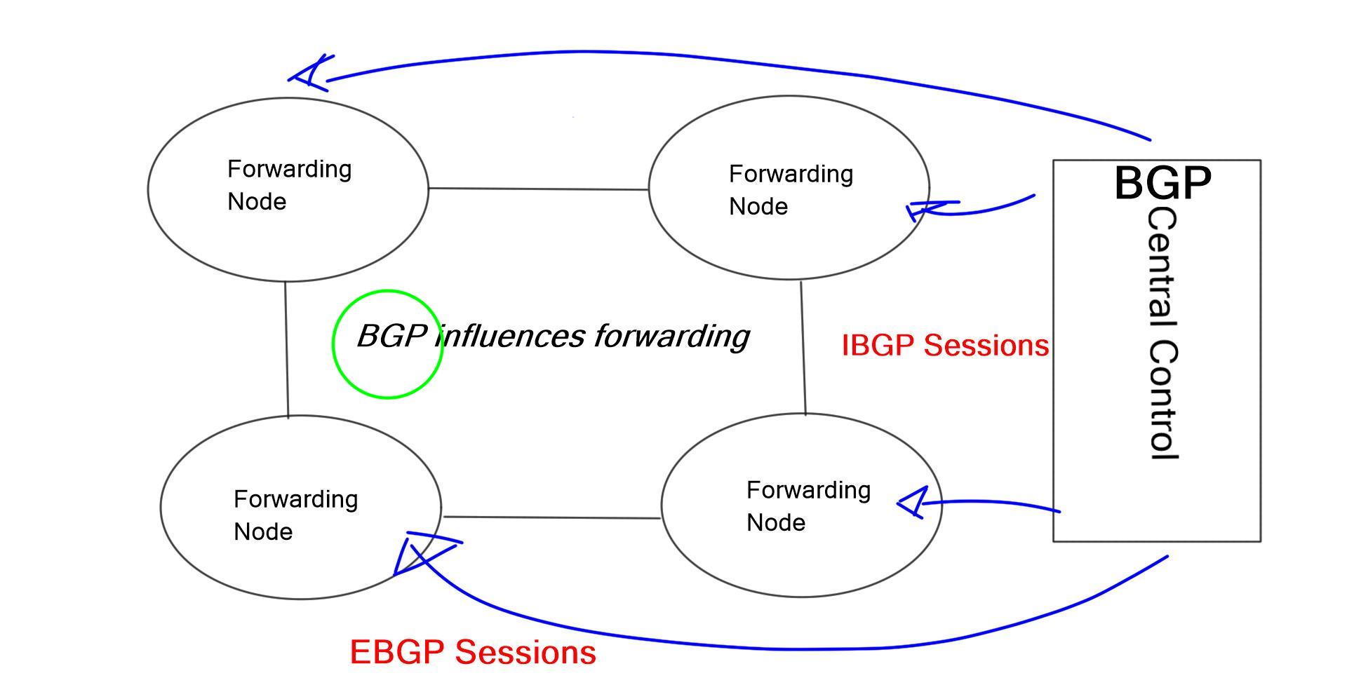
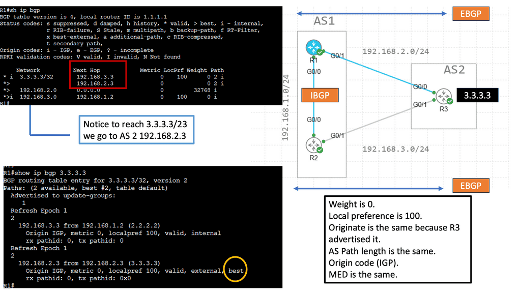
Border Gateway Protocol (BGP) exchanges reachability information between autonomous systems and can also support routing policy within a network. BGP traffic engineering generally involves influencing which routes are selected or how traffic enters and leaves a network, rather than directly measuring every path's live performance.

Technique Typical purpose Key limitation
Local preference Influence outbound route selection within an AS. Applies to the local routing policy domain; it does not directly command remote networks.
AS-path prepending Make an advertised route appear less attractive to some remote networks. Remote networks apply their own policies, so the result is not guaranteed.
Selective prefix advertisement Influence which destinations are reachable through particular upstreams. Requires careful prefix, policy and reachability planning.
Communities Signal policy requests to a provider or other BGP neighbour. The receiving network determines which communities it supports and honours.

BGP policy can influence traffic direction, but it should not be confused with a mechanism that automatically picks the lowest-latency path. Even when two providers offer different performance, the resulting route depends on BGP attributes, import and export policies, route availability and the decisions of other networks.

2.4 Policy-Based Routing: steer traffic by policy

Policy-Based Routing (PBR) allows forwarding decisions to be influenced by criteria beyond the destination-based routing lookup alone. Depending on the platform, a policy may match source addresses, protocol, ports, ingress interface or other packet attributes and then select a configured next hop or forwarding action.

  • Application-aware separation: send a defined class of traffic through a designated gateway or service path.
  • WAN selection: steer selected traffic toward a preferred circuit, subject to the platform's policy and tracking capabilities.
  • Service insertion: direct matching traffic through a firewall, inspection device or other network service.
  • Operational safeguards: account for unavailable next hops, asymmetric routing, return-path requirements and policy interactions.

PBR is powerful because it can provide fine-grained control, but overly broad rules can bypass intended routing behaviour or create asymmetric paths. Policies should be narrowly scoped, observable and tested against failure conditions.

2.5 Performance-based optimisation and PfR

Some network designs add a monitoring and policy layer that evaluates WAN-path performance and influences how traffic is distributed. Cisco Performance Routing (PfR), also known in later product generations as part of the Intelligent WAN family, is one example of this approach. Depending on platform and configuration, such systems can use traffic classes, reachability, delay, loss or utilisation-related information to guide path selection.

The key idea is to connect measurements to a controlled routing decision. Instead of assuming that a statically preferred path is always suitable, the system can evaluate whether traffic meets defined performance objectives and apply an allowed alternative when policy conditions are met.

Approach Primary control Best understood as
OSPF / IS-IS metric tuning Interior path cost Influencing shortest-path calculations.
ECMP Multiple equal-cost next hops Sharing eligible flows across paths.
BGP policy Route preference and advertisement Influencing route selection and traffic direction.
PBR Packet-matching rules Steering selected traffic using policy.
Performance-based WAN control Measured conditions plus policy Adapting path choice to defined objectives where supported.

2.6 A practical routing-engineering workflow

Routing changes should be treated as controlled engineering interventions. Establish a baseline, define the desired outcome and check how the change affects both the intended traffic and other traffic sharing the same infrastructure.

  • Identify the affected prefixes, applications, ingress points and egress links.
  • Determine whether the problem is route selection, flow distribution, congestion, QoS treatment or a physical fault.
  • Select the narrowest suitable mechanism: metric tuning, ECMP, BGP policy, PBR or a performance-aware control system.
  • Check convergence, redundancy, route-policy interactions and possible asymmetric forwarding.
  • Measure the outcome and retain a rollback plan if performance or reachability degrades.
Section takeaway

Routing-based traffic engineering offers several levels of control, from adjusting link-state metrics to distributing flows with ECMP, influencing BGP route policy and steering selected packets with PBR. The correct choice depends on what needs to be controlled. When traffic requires a deliberately constrained path rather than ordinary route preference, MPLS Traffic Engineering introduces another set of tools.

Interactive lab · 02

Routing-Based Traffic Engineering Lab

Explore how routing metrics, BGP policy, equal-cost paths and traffic classification can influence packet forwarding.

1. Configure the routing scenario

PBR can steer selected traffic using configured match rules. Other traffic may follow the normal routing table.
Ready to simulate.

2. Selected forwarding path

Illustrative network: R1 forwards traffic towards destination R4 over one of two paths.

R1 R2 R3 R4 Cost 10 Cost 10 Cost 20 Cost 20
Selected path Available alternative Unavailable link
Chosen path
R1–R2–R4
Path cost
20
Active paths
1
The upper path has the lower illustrative metric, so the metric-based strategy selects it.
Learning model, not a router emulator. The example metrics and BGP policy preferences are illustrative. Real BGP best-path selection follows implementation-specific rules and configured attributes; BGP does not inherently select the lowest-latency route from live performance measurements. ECMP requires eligible equal-cost routes and compatible forwarding configuration.
Section 03 · Engineer the Path

MPLS Traffic Engineering: RSVP-TE, Explicit Paths and Fast Reroute

Multiprotocol Label Switching (MPLS) Traffic Engineering gives network operators greater control over how selected traffic crosses a routed core. Instead of relying exclusively on each router's ordinary shortest-path forwarding decision, an engineered path can be established to follow a planned route and, where supported, meet configured resource constraints.

This is particularly useful in service-provider networks, enterprise WANs and large IP backbones where several links may be available between the same endpoints. A shortest path can be perfectly valid yet concentrate traffic on a small number of links, leaving other capacity underused. Traffic engineering provides tools for controlling that distribution.

Core concept: reachability and path engineering are different tasks

An IGP such as OSPF or IS-IS supplies topology and reachability information. MPLS Traffic Engineering can use that information, together with engineering constraints and signalling, to establish a specific label-switched path through the network.

3.1 Understanding the MPLS forwarding model

In an MPLS network, packets are forwarded using labels attached to packets or frames. A Label Edge Router (LER) commonly classifies incoming traffic and pushes an MPLS label at the ingress edge. Intermediate Label Switch Routers (LSRs) forward traffic by swapping labels. At or near the egress, the label is removed and the packet continues toward its destination.

Ingress Classify and label

The ingress router identifies the traffic or forwarding equivalence class and applies the appropriate label stack for the selected forwarding path.

Core Switch labels

Core routers use label-forwarding entries to send traffic toward the next hop without requiring a full IP route lookup for every transit packet.

Egress Remove or process labels

The egress side processes the label stack and forwards the traffic toward its destination according to the service design.

Control plane Establish forwarding state

Routing and label-distribution mechanisms provide the information needed to build the forwarding entries used by the data plane.

MPLS forwarding alone does not guarantee that traffic follows an optimised path. Conventional MPLS label-switched paths may follow the IGP's shortest-path calculations. MPLS Traffic Engineering adds mechanisms for selecting and signalling paths that may differ from that default.

3.2 What is an MPLS Traffic Engineering tunnel?

An MPLS-TE tunnel represents a logical forwarding path from an ingress router toward an egress router. The tunnel can be associated with a planned route, resource requirements and protection behaviour. Traffic is then mapped onto the tunnel using the routing and forwarding mechanisms supported by the implementation.

The physical topology remains unchanged. What changes is the selected route through that topology and the forwarding state used to carry the traffic. Multiple tunnels can be engineered for different destinations, traffic classes or operational requirements.

Define Specify endpoints and path constraints.
Signal Request path establishment and resources.
Forward Carry traffic over the established LSP.
Monitor Check path health and resource usage.

3.3 RSVP-TE and constrained path selection

Resource Reservation Protocol Traffic Engineering (RSVP-TE) is a signalling mechanism historically used to establish MPLS traffic-engineered label-switched paths. The ingress router determines a candidate path using available topology and constraint information, then uses RSVP signalling to request establishment along that path.

Intermediate routers participate in signalling and maintain the required path state. Depending on the configuration and network capabilities, a path may include explicit hops, bandwidth requirements, administrative constraints and protection preferences.

Engineering input What it helps control Design consideration
Explicit route Constrains the path to specified hops or route segments. Explicit hops must remain reachable and compatible with the intended design.
Bandwidth requirement Requests that the path satisfy supported reservation constraints. Reservations depend on configured link attributes and admission-control state; they do not create physical capacity.
Administrative constraints Include or exclude links based on configured attributes. Link attributes must be maintained accurately and consistently.
Path optimisation Select a feasible candidate according to the configured objective. A path that is optimal under configured metrics may not be optimal for every real-time application metric.

RSVP-TE can reserve resources according to the network's configured reservation model. This is different from simply assigning a high QoS priority to packets. A reservation does not automatically guarantee application performance under every failure or congestion condition, and its effectiveness depends on correct capacity planning and operational configuration.

3.4 Why engineered paths can improve utilisation

Imagine a core network with two possible routes between an ingress and an egress router. The IGP's preferred route crosses a heavily used link, while an alternative route has spare capacity but more hops. A traffic-engineered tunnel can be configured to use the alternative when the path satisfies the intended constraints.

The objective is not always to choose the path with the fewest hops. Depending on the service, the objective might be to avoid a constrained link, satisfy a bandwidth requirement, keep traffic away from a particular administrative domain or provide a path that is independent of the primary route.

Do not confuse path length with path quality

A longer route can sometimes provide better capacity distribution or resilience. However, additional hops can also add delay and operational complexity. Compare the candidate paths against the actual engineering objectives instead of assuming that either the shortest or longest path is inherently better.

3.5 Fast Reroute: protecting traffic against failure

Traffic engineering also addresses what happens when a link or router fails. Without a pre-established protection mechanism, traffic may depend on routing convergence before it can use a new path. Fast Reroute (FRR) mechanisms can provide a locally available backup forwarding action intended to protect traffic while broader recovery takes place.

  • Link protection: aims to keep traffic moving when a particular link fails, using an eligible alternate path.
  • Node protection: aims to protect against failure of a downstream router where a suitable bypass is available.
  • Backup path design: requires an alternate that is genuinely independent of the protected resource where possible.
  • Post-failure capacity: the backup must be able to carry the redirected load without creating a new unacceptable bottleneck.

Protection is not the same as eliminating failure. A backup may be unavailable, share a common risk with the primary path or become congested when traffic shifts. Engineers should test failure scenarios and verify both the switchover behaviour and the resulting forwarding path.

3.6 MPLS-TE in modern network design

RSVP-TE remains important in many established networks, but it is not the only approach to traffic-engineered paths. Segment Routing can encode a path using a sequence of segments and may reduce the need to maintain per-tunnel signalling state at every transit router, depending on the architecture. The best choice depends on existing infrastructure, operational skills, interoperability and service requirements.

Whichever technology is used, the engineering process remains similar: define the objective, understand the topology, calculate a feasible path, install forwarding state, monitor performance and plan for failures. Traffic engineering is effective when the control-plane design is supported by accurate telemetry and disciplined operational practice.

Section takeaway

MPLS Traffic Engineering extends ordinary routing by allowing selected traffic to use engineered label-switched paths. RSVP-TE can signal explicit or constrained paths and support reservation and protection mechanisms. The next section moves from distributed routing and signalling toward SDN and OpenFlow, where a controller can coordinate forwarding decisions across multiple devices.

Interactive lab · 03

MPLS Traffic Engineering Workbench

Build a constrained path, inspect illustrative MPLS labels, and test what happens when a link fails with or without a pre-planned Fast Reroute backup.

1. Configure the LSP

40 Mbps
Each link advertises an illustrative available bandwidth value.
FRR can switch traffic to a pre-established local repair path when the protected failure is detected and the backup is usable.
Ready to simulate.

2. Inspect the selected path

Cost 10 Cost 10 Cost 15 Cost 15 Cost 5 R1 R2 R3 R4 Ingress Egress
Active LSPFRR repair pathFailed link
Selected route
R1–R2–R4
Path cost
20
Bandwidth fit
Pass
Illustrative label at R1Push 16001
Transit actionSwap 16002
Egress actionPop label
The explicit LSP follows R1–R2–R4. Label operations and path feasibility are illustrative.
Educational model only. Label values are fictional examples, not live router state. The simulation approximates path constraints using link bandwidth and illustrative costs. RSVP-TE signalling, admission control, label distribution, CSPF, failure detection and FRR behaviour depend on the real network's configuration and platform.
Section 04 · Centralised Control

SDN, OpenFlow and Centralised Traffic Engineering

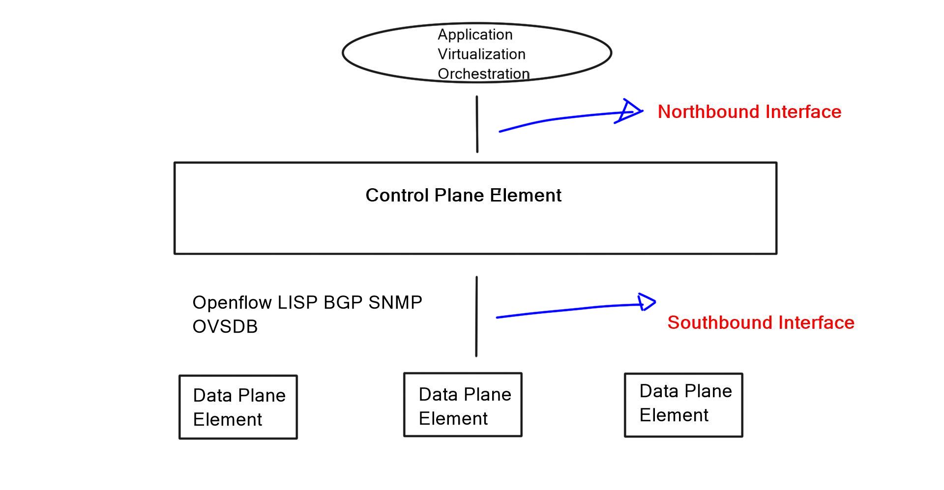
Software-Defined Networking (SDN) introduces a programmable approach to network control. Rather than relying exclusively on independent configuration and distributed routing decisions at each device, an SDN architecture can give a controller a broader view of network topology, policy and observed conditions. The controller can use that view to calculate forwarding decisions and coordinate changes across supported devices.

This is valuable for traffic engineering because congestion and inefficient path selection are often network-wide problems. A link may look attractive from the perspective of one router while using it could overload a shared resource elsewhere. A controller with sufficiently current topology and telemetry can evaluate a wider set of alternatives before deploying a policy.

SDN is an architecture, not a single protocol

A controller-based design may use OpenFlow, NETCONF, gNMI, APIs or vendor-specific interfaces, depending on the devices and architecture. OpenFlow is one protocol associated with SDN; not every SDN system uses it.

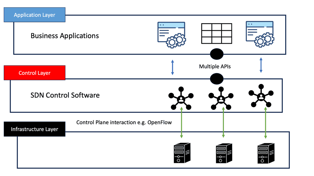
4.1 The main components of an SDN design

Application layer Express the objective

Applications describe the intended policy, such as prioritising a traffic class, selecting a path or avoiding a constrained link.

Control layer Analyse and decide

The controller evaluates available topology, policy, device capabilities and telemetry to calculate an appropriate forwarding strategy.

Infrastructure layer Forward the traffic

Switches and routers apply supported forwarding rules or configuration changes to implement the selected behaviour.

Feedback Observe the outcome

Counters, events and measurements help the system assess whether the policy is working and whether another action is required.

4.2 How OpenFlow can influence forwarding

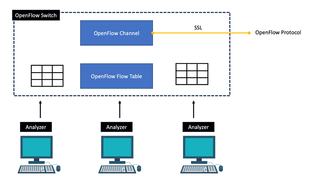
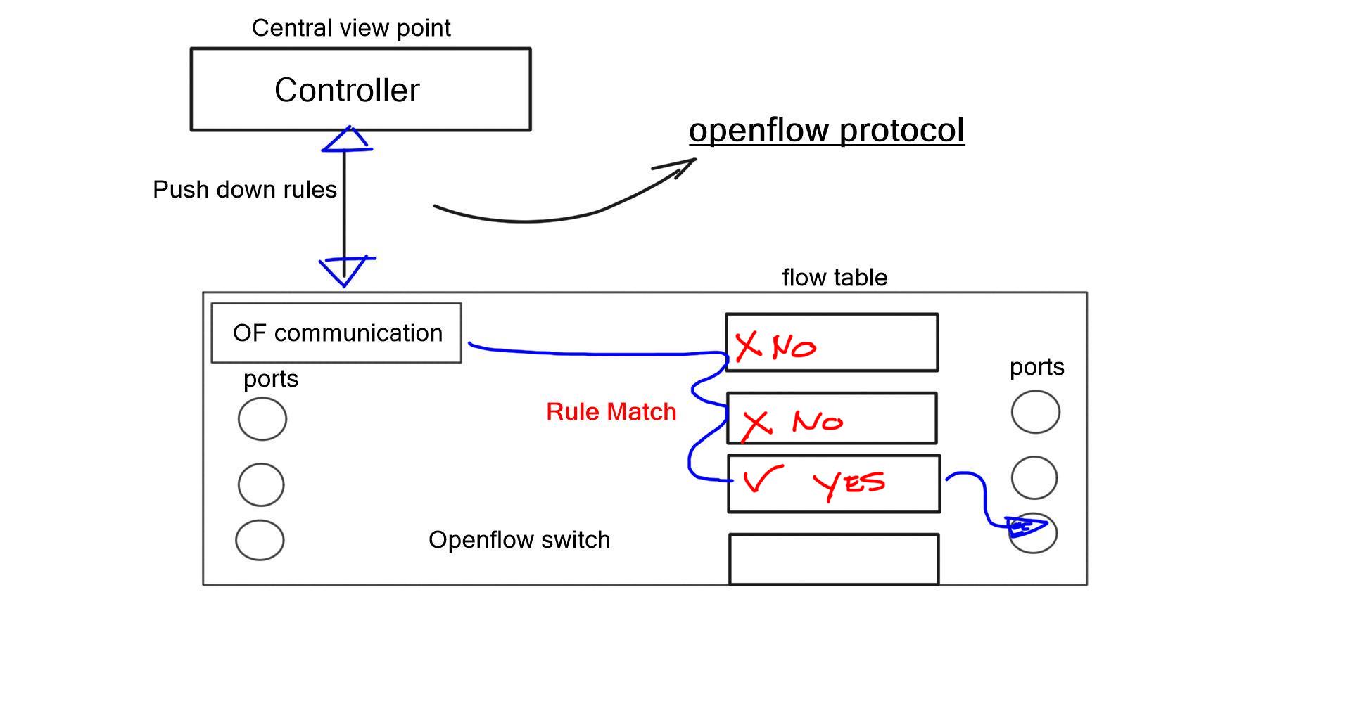
OpenFlow defines a protocol through which a controller can communicate with compatible forwarding devices. In an OpenFlow-capable switch, flow tables contain entries that match packet fields and specify actions, such as forwarding a packet to a port, modifying supported fields or sending selected traffic to the controller.

The controller can install, modify or remove flow entries according to its application logic and the capabilities of the switch. This enables explicit control over matching traffic, although the exact match fields, actions, table pipeline and hardware support depend on the OpenFlow version and implementation.

Collect Read topology and device information.
Calculate Evaluate paths and policy constraints.
Install Apply compatible forwarding rules.
Verify Observe counters and traffic outcomes.

A controller does not magically gain control over every device in the network. Devices must expose a compatible interface, the controller must understand their capabilities, and the design must account for existing forwarding state and other control-plane systems.

4.3 Centralised path selection using network metrics

A traffic-engineering controller can score candidate paths against defined objectives. For example, a policy might reject paths that fail a bandwidth requirement, penalise paths with high observed delay, avoid links with excessive loss, and prefer a suitable path with more available capacity.

A simplified illustrative scoring model could combine normalised measurements:

Illustrative path score

Path score = (latency weight × latency score) + (loss weight × loss score) + (jitter weight × jitter score) + (utilisation weight × utilisation score).
In this example, lower scores are preferred. Real systems must define normalisation, units, thresholds, missing-data handling and hard constraints carefully.

This model is a conceptual example, not a standard OpenFlow algorithm. A production controller may use graph algorithms, constraint-based path computation, optimisation solvers or simpler policy rules. Measurements can also be stale or noisy, so a robust system avoids changing paths in response to every small fluctuation.

4.4 Example: selecting a path through a diamond topology

Consider a source router connected to two intermediate routers, both of which can reach the same destination. One candidate path has lower latency but is approaching its capacity limit. The other has slightly higher latency but more spare bandwidth. A controller can evaluate both against the application's policy and select a path that meets the required performance and capacity objectives.

Candidate path Observed condition Possible policy result
Path A Low latency, but high utilisation. Prefer it for delay-sensitive traffic only if capacity constraints remain satisfied.
Path B Moderate latency, more spare capacity. Prefer it for a high-volume flow if it meets the application's delay limit.
Backup path Available alternative with acceptable failure-domain separation. Retain as a recovery option if the primary path becomes unavailable.

The right answer depends on the service objective. A video-conferencing flow may be sensitive to delay and jitter, while a large replication flow may place greater emphasis on sustained throughput. The controller should evaluate traffic against explicit requirements rather than applying one universal ranking to every application.

4.5 Centralised control versus distributed routing

Centralised and distributed control are not mutually exclusive. Many networks use a distributed IGP or BGP for basic reachability while a controller provides additional policy, automation or traffic-engineering decisions. This combination can preserve the strengths of established routing while introducing more coordinated control.

Consideration Distributed routing Controller-based control
Decision scope Routers make decisions using their protocol state and configured policies. A controller can evaluate a broader topology view, subject to the data it receives.
Convergence and updates Protocols exchange updates and recalculate routes as network state changes. Changes depend on controller logic, telemetry, device interfaces and deployment behaviour.
Programmability Typically configured through routing policies and device features. Can support policy automation and coordinated changes through software.
Failure considerations Distributed protocols can continue operating according to their local state and design. Requires controller availability, secure communication and a strategy for stale or lost control connectivity.
Operational complexity Familiar protocols, but potentially many separate device configurations. Centralised automation can simplify operations, but introduces software, integration and policy-validation requirements.

4.6 Stability, security and safe deployment

A centralised view can improve coordination, but poorly designed control loops can cause traffic to oscillate between paths. If several flows are moved at once, the new path may become congested, triggering another round of changes. Telemetry delay can make the controller react to conditions that no longer exist.

  • Use guardrails: define capacity limits, acceptable performance ranges and policy constraints before deploying changes.
  • Reduce oscillation: use thresholds, hold-down periods or hysteresis where appropriate to avoid unnecessary path changes.
  • Validate first: test controller decisions and device compatibility in a lab or limited deployment.
  • Secure the control channel: restrict access, authenticate components and protect controller APIs and management interfaces.
  • Plan for controller failure: define what devices should do when controller connectivity is lost or policy information becomes stale.
  • Keep a rollback path: record previous configuration and provide a tested recovery procedure.
Visibility must lead to verified action

A controller may calculate an excellent theoretical path, but success depends on whether the forwarding devices can implement it, whether the route remains available, and whether measured application performance improves after deployment.

4.7 Where SDN fits in the traffic-engineering toolkit

SDN is most useful when policy and forwarding decisions benefit from coordination across devices or when repetitive changes can be automated safely. It can complement IGP metrics, BGP policy, ECMP, MPLS-TE and QoS rather than replacing every existing mechanism.

The practical goal is to connect network-wide intent with measurable outcomes. A controller should understand what the network is trying to achieve, choose a feasible action, deploy that action through supported interfaces, and verify that the result matches the objective.

Section takeaway

SDN enables programmable, coordinated traffic control, while OpenFlow is one possible interface for managing forwarding rules on compatible devices. Centralised visibility can support more deliberate path selection, but dependable traffic engineering still requires accurate telemetry, stable control logic, secure interfaces and a tested failure strategy. The next section examines how these principles apply to cloud networking, load balancing and Kubernetes.

Interactive lab · 04

SDN Controller & Traffic Engineering Lab

Compare distributed shortest-path routing with controller-selected paths. Change link utilisation, simulate a failure, and inspect the illustrative forwarding decision.

1. Configure the network

85%
Illustrative utilisation for the R1–R2–R4 path.
35%
Illustrative utilisation for the R1–R3–R4 path.
Uncheck this to model a controller-dependent decision that cannot be updated. Existing forwarding may persist, but adaptation is not assumed.
Ready to simulate.

2. View the forwarding decision

SDN Controller Upper path Utilisation Lower path Utilisation R1 R2 R3 R4 Ingress → selected path → egress
Selected forwarding pathUnavailable path
Selected path
R1–R3–R4
Modelled utilisation
35%
Decision state
Installed
The controller selects the less-utilised path in this illustrative model. Real SDN decisions depend on telemetry, policy, controller logic and the capabilities of the forwarding devices.
Educational model only. The utilisation values are illustrative inputs, not measured network telemetry. OpenFlow is one protocol that can be used between a controller and compatible switches; SDN can also use other southbound interfaces. A controller does not automatically provide global optimisation unless its data, policies and control logic support it.
Section 05 · From Network to Application

Cloud, Kubernetes and Application Traffic Engineering

Traffic engineering extends beyond traditional routers and WAN circuits. In cloud and container environments, performance depends on how virtual networks route packets, how load balancers distribute requests, how applications are deployed across regions, and which services are permitted to communicate. These mechanisms operate at different layers, but they all influence the path or destination that traffic takes.

A useful design begins by distinguishing network routing from request distribution and security policy. A virtual network route determines where packets are forwarded next. A load balancer chooses a backend or service endpoint for a connection or request. A Kubernetes NetworkPolicy defines permitted communication between selected workloads, subject to the network plugin's implementation. These controls complement one another rather than replacing one another.

Three different control problems

Routing answers, “Where should packets go next?” Load balancing answers, “Which eligible backend should handle this traffic?” Network policy answers, “Which communications are allowed?” Confusing these responsibilities can lead to ineffective optimisation or security gaps.

5.1 Cloud virtual networks and route selection

Cloud platforms provide virtual networking constructs such as virtual private clouds, subnets, route tables, gateways, peering connections and private connectivity services. Together, these determine how traffic moves between workloads, services and external networks.

In Google Cloud, for example, Virtual Private Cloud (VPC) routes participate in forwarding decisions within the supported network environment. Route destinations, next-hop types, route priority and other platform-specific rules affect which route is selected. VPC peering can provide private connectivity between eligible networks, but it does not automatically make every route transitive across a chain of peerings.

Route tables Control packet forwarding

Routes associate destination ranges with next hops. Engineers should check route priority, destination specificity, reachability and the supported next-hop type.

Network connectivity Connect workloads and networks

Peering, VPNs, dedicated connectivity and gateways provide different connectivity models, each with its own routing and reachability constraints.

Observability Trace actual traffic behaviour

Flow logs, route inspection, health information and application telemetry help identify where traffic is delayed, dropped or sent along an unexpected path.

Capacity planning Match demand to resources

Regional capacity, service quotas, network limits and workload placement can constrain the available options even when a route exists.

Cloud routing is not identical to physical-router routing. Providers implement their own control planes and forwarding rules, and some behaviour is managed by the platform rather than exposed as a customer-configurable protocol. Engineers should use the provider's documented route-selection and connectivity model when diagnosing a cloud traffic path.

5.2 Load balancing: distributing connections and requests

Load balancing distributes eligible traffic across a set of backend services or endpoints. Depending on the product, a load balancer may operate at Layer 4, making decisions using transport-layer information, or at Layer 7, where HTTP attributes and application-level information can influence routing.

Client Sends a connection or request.
Load balancer Evaluates policy and backend health.
Backend pool Receives traffic on selected endpoints.

Backend selection may consider health checks, configured balancing policies, locality, connection persistence, capacity or other product-specific criteria. The exact behaviour varies by load balancer type, so engineers should not assume that every service chooses the backend with the lowest live latency.

Mechanism Primary responsibility Example use
Network routing Forwards packets toward a destination or next hop. Reach a workload subnet through a valid virtual route.
Layer 4 load balancing Distributes transport connections or flows. Spread TCP or UDP traffic across eligible backends.
Layer 7 load balancing Routes application requests using supported application attributes. Send requests to different services based on host or URL rules.
Health checks Determine whether a backend is eligible to receive traffic. Stop sending new traffic to an unhealthy service endpoint.

5.3 Cross-region traffic engineering

Applications deployed in multiple regions can improve availability and serve users from geographically distributed locations. However, distributing traffic across regions introduces decisions about latency, regional capacity, data locality, cost, service dependencies and disaster recovery.

Global or cross-region load balancing can direct traffic to eligible backends in different locations according to the service's supported selection model. A well-designed policy considers backend health and regional availability while avoiding a configuration in which one region becomes overloaded during a surge or a regional failure.

  • Latency and proximity: consider where users are located and how application response time varies by region.
  • Regional capacity: ensure each region can support its expected demand and any planned failover load.
  • Health and readiness: verify that the service can safely receive requests before sending traffic to it.
  • Data dependencies: account for replication delay, state consistency and services that are available in only one region.
  • Cost and egress: evaluate the financial impact of cross-region traffic and data transfer.
  • Failure testing: verify how traffic is redistributed when a region or backend pool becomes unavailable.
Failover must be capacity-aware

A second region is not a complete resilience strategy if it cannot handle the workload displaced by a failure. Test realistic traffic volumes and dependencies, not just whether a health check causes traffic to move.

5.4 Kubernetes networking and NetworkPolicy

Kubernetes introduces additional networking layers because applications run in pods that can be created, moved, scaled or replaced dynamically. Services provide stable ways to reach groups of pods, while ingress controllers, gateways or service meshes can provide further traffic-management capabilities depending on the cluster architecture.

Kubernetes NetworkPolicy is primarily a traffic-permission mechanism. It specifies which connections are allowed to or from selected pods, based on supported selectors and rules. It does not, by itself, choose the lowest-latency route, distribute traffic evenly between pods or guarantee that a particular path will be used. Enforcement requires a network implementation that supports NetworkPolicy.

Service Provide stable service access

A Kubernetes Service provides a stable abstraction for reaching a group of eligible endpoints, while the cluster's data plane handles traffic forwarding.

Ingress or gateway Control external application entry

Supported ingress or gateway implementations can route application traffic toward services using their configured rules and capabilities.

NetworkPolicy Restrict permitted connections

Policy rules can limit communication between workloads and other permitted peers, reducing unnecessary network exposure.

Telemetry Observe workload performance

Application metrics, service-level indicators, flow data and cluster events help distinguish network problems from application or resource bottlenecks.

5.5 Application-aware traffic steering

Application-aware steering makes forwarding or backend decisions using information about the service, request or traffic class. Depending on the architecture, this may be implemented by an application load balancer, API gateway, service mesh, SDN controller or a policy-aware WAN platform.

Consider a service that has both a current application version and a legacy version. A request can be directed according to a validated application-version header, authenticated identity, hostname or route rule. Such decisions should be made at the appropriate application-aware layer rather than assuming that ordinary IP routing understands application identity.

Steering input Possible decision Safeguard
Host or URL path Send a request to a matching application service. Validate routing rules and avoid exposing unintended endpoints.
Authenticated identity Apply access or service-routing policy for an authorised user or client. Verify identity tokens and enforce authorisation server-side.
Application version Direct eligible requests to a new or legacy service. Validate the version value and do not trust a client-supplied header on its own.
Backend health Remove unhealthy endpoints from new traffic selection. Use meaningful health checks and test recovery behaviour.

Headers such as X-App-Version are ordinary request metadata, not proof of identity or permission. A client may be able to alter them. If a decision affects access or sensitive operations, validate the request against trusted authentication and authorisation information, and enforce the rule at a trusted gateway or service boundary.

5.6 Combining the controls into one design

Consider an application deployed across two cloud regions, with several Kubernetes services behind regional load balancers. The network route table provides connectivity between the relevant components. Regional load balancers select healthy backends. Kubernetes Services provide stable access to pods, while NetworkPolicy restricts permitted workload communication. Application-level rules may then steer requests based on service paths or validated identity.

If users experience slow responses, engineers should investigate each layer independently before changing the design. The problem might be a route issue, overloaded backend, unhealthy pod, cross-region dependency, restrictive network policy or slow application query. A change at the wrong layer can hide the symptom without correcting its cause.

  • Trace the request path from the client through the load balancer, network and application service.
  • Check route selection and connectivity between the relevant networks and subnets.
  • Review backend health, endpoint availability and regional utilisation.
  • Verify that NetworkPolicy permits the required communication without granting unnecessary access.
  • Correlate network measurements with application latency, errors and resource metrics.
  • Test scaling, backend loss and regional failover under representative demand.
Section takeaway

Cloud and application traffic engineering combines several distinct controls: virtual routes determine packet forwarding, load balancers distribute connections or requests, Kubernetes networking connects workloads, and NetworkPolicy restricts permitted communication. The strongest designs coordinate these layers while measuring the actual outcome. The next section moves back toward WAN engineering, including DMVPN, NHRP and IPv6 path behaviour.

Interactive lab · 05

Cloud & Kubernetes Traffic Engineering Lab

Choose a traffic-steering layer, vary application demand, and simulate an unhealthy backend. See how cloud routing, load balancing and Kubernetes service selection solve different problems.

1. Configure traffic delivery

120 req/s
Illustrative requests per second reaching the service.
If disabled, this simplified model may send traffic to an unhealthy backend, illustrating the importance of health-aware selection.
Ready to simulate.

2. Inspect the delivery path

Incoming requests Cloud routing layer Backend A Backend B Backend C 40 req/s 40 req/s 40 req/s Illustrative backend distribution
Selected delivery pathUnused or unavailable path
Traffic delivered
120 req/s
Active backends
3 of 3
Unserved demand
0 req/s
Network layerRoute selection
Service layerBackend selection
App layerRequest policy
A cloud network route determines where packets are forwarded. A load balancer or service proxy selects a backend; these functions are related but not interchangeable.
Educational model only. Requests are divided evenly or by a simplified policy; no real cloud account, Kubernetes cluster, health probe, or application header is accessed. Kubernetes Services distribute traffic according to the cluster's networking implementation and endpoint state. Application-provided headers are not trusted identity unless validated by a trusted component.
Section 06 · Engineer the WAN

WAN Traffic Engineering: DMVPN, NHRP and IPv6

Wide Area Network (WAN) traffic engineering must account for more than the route selected by a routing protocol. Enterprise WANs often combine hub-and-spoke connectivity, encrypted tunnels, multiple transport circuits and remote branches with different bandwidth and latency characteristics. The engineering challenge is to direct traffic appropriately, make efficient use of available paths and preserve connectivity when links or tunnels fail.

Dynamic Multipoint VPN (DMVPN), the Next Hop Resolution Protocol (NHRP), routing policy and IPv6 neighbour and router-discovery mechanisms solve different problems within this environment. Understanding their roles helps engineers distinguish tunnel establishment and address resolution from route selection and traffic optimisation.

Keep the functions separate

DMVPN provides a framework for dynamic multipoint tunnel connectivity. NHRP helps spokes discover the tunnel endpoint information needed for direct communication. Routing protocols determine network reachability, while routing policy and supported path-selection features influence which available route traffic uses.

6.1 DMVPN: flexible hub-and-spoke connectivity

DMVPN is a Cisco networking architecture commonly built from multipoint GRE (mGRE), NHRP and IPsec. It enables a hub-and-spoke VPN design in which remote sites can use a shared multipoint tunnel interface rather than requiring a separately configured static GRE tunnel for every possible spoke-to-spoke connection.

Multipoint GRE Provide tunnel encapsulation

mGRE supports multiple tunnel destinations through a multipoint interface, allowing the architecture to scale more flexibly than a collection of individually configured point-to-point GRE tunnels.

NHRP Resolve remote tunnel endpoints

NHRP allows a spoke to register its tunnel information with a hub and discover the mapping needed to communicate directly with another spoke when the design supports it.

IPsec Protect tunnel traffic

IPsec can provide confidentiality, integrity and peer authentication according to the configured security policy and negotiated parameters.

Routing protocol Exchange reachability

A supported routing protocol can advertise branch prefixes and provide the route information needed to send traffic through the overlay.

6.2 DMVPN phases and direct spoke-to-spoke traffic

DMVPN designs are commonly described in phases. The phase influences how routing information and next-hop behaviour interact with NHRP and whether direct spoke-to-spoke forwarding can be established.

DMVPN phase Typical behaviour Traffic-engineering consideration
Phase 1 Spoke-to-spoke traffic typically traverses the hub. Simple centralised forwarding, but the hub can become a bandwidth or latency bottleneck.
Phase 2 Direct spoke-to-spoke tunnels can be established, with routing and next-hop requirements that preserve the remote spoke as the next hop. Can reduce hub transit, but route summarisation and next-hop handling require careful design.
Phase 3 NHRP redirect and shortcut mechanisms can help spokes discover and establish direct paths while allowing more scalable hub-oriented routing designs. Can improve direct-path efficiency, but depends on compatible configuration and correct operation of the redirect and shortcut process.

Exact configuration requirements vary by platform and software version. The phase label alone does not guarantee a particular path: verify the installed route, next-hop resolution, NHRP state and actual forwarding behaviour.

6.3 How NHRP shortcuts change the traffic path

In a hub-and-spoke overlay, the hub may initially provide reachability between two spokes. When a spoke sends traffic toward a remote branch, the hub can identify an opportunity for direct communication and send an NHRP redirect in a supported Phase 3 design. The source spoke can then use NHRP to resolve the remote spoke's tunnel endpoint and establish a shortcut path.

Initial traffic Spoke A forwards toward Spoke B through the hub.
Redirect The hub indicates that a shortcut may be appropriate.
NHRP resolution Spoke A discovers the remote tunnel endpoint.
Direct path Eligible traffic can travel between the spokes.

A shortcut can reduce unnecessary hub transit and may improve latency or relieve hub capacity. However, a direct tunnel is not automatically the fastest or most resilient path. The underlay Internet or private WAN path between spokes may have different delay, loss and capacity characteristics, and the tunnel still depends on valid routing and security state.

Measure the overlay and the underlay

If a DMVPN application performs poorly, inspect both the logical overlay route and the physical or provider path carrying the tunnel. Tunnel state alone does not prove that the underlying transport is healthy or that the selected route meets the application's needs.

6.4 Routing policy across multiple WAN paths

Many enterprise WANs have more than one available transport, such as broadband Internet, private WAN connectivity or cellular backup. Routing metrics and policy can influence which path is preferred, while platform-specific tracking or performance-based WAN features may respond to reachability or measured conditions.

  • Primary and backup paths: define a preferred route and verify that an alternate becomes usable when the primary fails.
  • Traffic separation: use supported routing policy or PBR to direct selected traffic through an appropriate WAN service.
  • Dynamic tunnel selection: consider which peers and tunnel endpoints remain reachable after an underlay change.
  • Capacity and cost: account for circuit bandwidth, data-transfer costs and the demand expected during failover.
  • Asymmetric forwarding: check whether outbound and return traffic follow compatible paths, particularly when stateful firewalls or NAT are involved.

Basic route preference does not inherently measure real-time latency or loss. Where a design requires application-specific performance objectives, use an appropriate performance-monitoring and path-selection capability rather than assuming that a lower routing metric always identifies the best-performing circuit.

6.5 IPv6 Router Advertisements and path preference

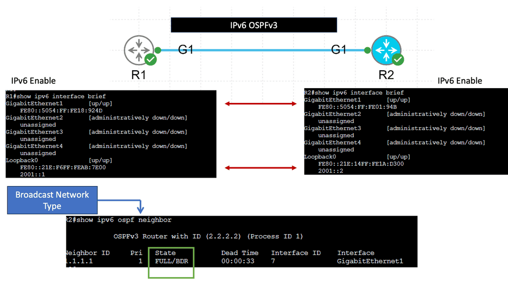
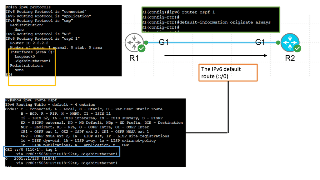
IPv6 introduces its own mechanisms for discovering routers and learning default-router information. Hosts can receive Router Advertisements (RAs) through Neighbor Discovery, with information such as router preference helping a host distinguish between advertised default routers when the relevant conditions and implementations support that behaviour.

Router preference is not a general-purpose traffic-engineering metric. It does not directly measure bandwidth, application latency or packet loss. It helps influence a host's choice among eligible default routers, while broader IPv6 route selection also depends on the destination, routing table and other applicable rules.

IPv6 mechanism Purpose What it does not guarantee
Router Advertisement Advertises router and network information to IPv6 hosts. Does not automatically identify the lowest-latency upstream path.
Default-router preference Helps distinguish advertised default routers according to supported preference rules. Does not guarantee that the preferred router has more capacity or better performance.
IPv6 routing protocol Provides routes and reachability within the relevant routing domain. Does not automatically optimise every application flow using real-time metrics.
Policy and monitoring Can guide path choice based on defined operational objectives. Cannot compensate for missing telemetry, incorrect policy or unavailable connectivity.

6.6 WAN failure handling and validation

A resilient WAN design must be tested under failure, not just during normal operation. A tunnel can remain configured while its underlying path has degraded, and a routing change can restore reachability without restoring acceptable application performance.

  • Confirm that the expected routes are installed and that next hops resolve correctly.
  • Inspect tunnel state, NHRP mappings and shortcut behaviour where applicable.
  • Measure delay, jitter, loss and throughput over the actual traffic path.
  • Simulate loss of a circuit, hub or remote endpoint and verify recovery behaviour.
  • Check firewall, NAT and security-association behaviour when traffic moves between paths.
  • Confirm that backup capacity is sufficient for the traffic redirected during failure.
  • Review IPv6 Router Advertisements and default-router behaviour separately from IPv4 routing.
Section takeaway

WAN traffic engineering combines routing policy, tunnel architecture, endpoint discovery and failure planning. DMVPN and NHRP can support dynamic branch connectivity and direct spoke-to-spoke paths, while IPv6 Router Advertisements influence host-side router discovery. None of these mechanisms alone guarantees optimal performance: validate the installed routes, tunnel state, underlying transport and measured application outcomes. The next section brings these principles together in an interactive traffic-engineering lab.

Interactive lab · 06

WAN Traffic Engineering Workbench

Explore DMVPN phases, NHRP shortcut behaviour, WAN link failures, and IPv6 default-router preference in one illustrative topology.

1. Configure the WAN

80 ms
Illustrative one-way delay estimate for the hub-mediated path.
30 ms
Illustrative one-way delay estimate for a direct spoke-to-spoke path.
This illustrates RFC 4191 router preference, not latency measurement.
Ready to simulate.

2. Inspect the WAN path

A–Hub Hub–B Spoke shortcut HUB A B WAN overlay
Selected pathNHRP shortcutUnavailable tunnel
Forwarding path
A → B direct
Modelled delay
30 ms
Shortcut state
Formed
IPv6 default-router selection example
Router A preferenceMedium
Router B preferenceHigh
Illustrative preference outcomeRouter B preferred
In Phase 3, NHRP can help spokes discover a direct shortcut after traffic initially traverses the hub. Exact behaviour depends on platform, configuration, routing and tunnel state.
Educational model only. Delay values are user-entered illustrations, not live measurements. DMVPN phase behaviour depends on implementation and configuration. NHRP resolves protocol next-hop information and can support shortcut formation; it does not guarantee a faster path. IPv6 Router Advertisement default-router preference expresses High, Medium or Low preference and is not a live latency or performance metric.
Section 07 · Interactive lab

Interactive Traffic Engineering Lab: Compare Paths, Manage Congestion and Protect Resilience

Traffic engineering turns network measurement into a forwarding decision. In this simplified lab, you will compare two paths across a small WAN, inspect latency and utilisation, and see how a failed link can change the preferred route.

The topology and metrics are illustrative, not live measurements. They represent a network in which a traffic engineer must balance delay, link utilisation and resilience rather than choosing a route based on hop count alone.

Lab objective

Choose a routing strategy, adjust the demand placed on the network and simulate a link failure. Observe how the selected path changes, then consider whether the lowest-latency path is also the best operational choice.

Path Selection Workbench Source: Edge A · Destination: Edge D · Two candidate routes through a diamond-shaped WAN.
Selected path A–C–D
Estimated latency 28 ms
Peak link utilisation 55%
Path status Available
Interactive diamond WAN topology Edge A connects to routers B and C, which each connect to destination D. The highlighted route indicates the currently selected path. 40 ms · 70% 35 ms · 65% 15 ms · 45% 13 ms · 55% A B C D Source Destination Illustrative WAN · Values are simulated
Selected route Available alternative Failed link
ROUTE SELECTED Balanced path selected

The lower path offers a lower estimated latency in this example. The selected strategy also considers utilisation when comparing candidate routes.

7.1 Understand the simulated network

The WAN uses four routers and two end-to-end candidate paths. The upper route passes through B, while the lower route passes through C. Each link has a baseline latency and utilisation value. The simulation distributes the additional offered load across the links of the selected path and estimates a congestion-related delay penalty as utilisation rises.

Candidate path Baseline latency Initial peak utilisation Engineering consideration
A–B–D 75 ms 70% Higher baseline delay and less headroom on its most utilised link.
A–C–D 28 ms 55% Lower baseline delay and more headroom in the initial example.

7.2 Experiment with the routing strategy

  • Lowest estimated latency: selects the available path with the lowest modelled delay, including the simulation's congestion penalty.
  • Balanced latency and utilisation: scores candidate paths using both estimated delay and peak link utilisation.
  • Prefer lower utilisation: favours the route with more remaining headroom, while still considering estimated delay.
  • Manual selection: lets you choose a path directly and compare it with the automatic strategies.

These are teaching strategies, not exact implementations of OSPF, IS-IS, BGP, RSVP-TE or a commercial SD-WAN controller. Real networks use protocol-specific metrics, policies and constraints. A routing protocol does not automatically use live latency and utilisation simply because those measurements are available elsewhere.

7.3 Simulate congestion and link failure

Increase the offered load to see how the selected route's modelled utilisation and delay change. Then select Simulate upper-link failure. The upper route becomes unavailable, and the automatic strategies must use the remaining path. If the manually selected route is no longer available, the lab reports that condition rather than silently claiming that the manual choice succeeded.

What this demonstrates

A path that looks attractive under normal conditions may lose its advantage when demand increases or a link fails. Traffic engineering should consider performance, capacity, policy and resilience together, and should be validated with actual telemetry and failure testing before being deployed.

7.4 Engineering review checklist

  • Are latency, loss and utilisation measured on the same traffic path and over a suitable time window?
  • Does the selected route have sufficient capacity for expected demand and failover traffic?
  • Are primary and backup paths genuinely independent, or do they share a circuit, provider or physical conduit?
  • Can routing policy and security controls accommodate a path change?
  • Does the recovery process restore acceptable application performance, not merely basic reachability?
  • Are the path-selection decisions observable, explainable and reversible?
Section takeaway

Traffic engineering is a continuous process of measurement, path selection, validation and adjustment. Use the lab to explore trade-offs, then apply the same reasoning to routing policy, MPLS traffic engineering, SDN controllers and WAN designs. In production, base decisions on trustworthy telemetry, documented objectives and repeatable tests—not on an illustrative score alone.

Network Insight · Interactive Lab 07

Traffic Engineering Scenario Challenge

Can you deliver the traffic without overloading a link? Choose a strategy, change demand and capacity, then introduce a failure to test the outcome.

1. Configure the network
Traffic demand 120 Mbps
R1 → R2 → R4 100 Mbps
R1 → R3 → R4 80 Mbps
Scenario objective

Maximise delivered traffic, avoid exceeding available path capacity, and maintain a usable route after a failure. The best strategy depends on the demand and network conditions.

R1 Ingress R2 Upper R5 Upper R3 Lower R6 Lower R4 Destination UPPER PATH · illustrative delay 18 ms LOWER PATH · illustrative delay 32 ms
Upper path Lower path Unavailable or unused
Delivered traffic
120 Mbps
Unserved traffic
0 Mbps
Estimated path delay
18 ms
Traffic delivered
100%
2. Scenario result
Scenario ready

Run the scenario to evaluate the selected strategy against available path capacity.

Demand successfully delivered 100%
Upper: idle Lower: idle No failure
Engineering takeaway

Path choice is only one part of traffic engineering. Capacity, demand, failures and policy all influence the result.

Educational model only. Delay values are illustrative; this lab does not implement live routing, QoS queues, BGP, RSVP-TE or a production traffic controller.

Network Insight · Engineering Summary

Network Traffic Engineering: Key Takeaways

Network traffic engineering is the practice of directing, distributing and managing traffic to make effective use of network resources. It connects routing policy, link capacity, Quality of Service (QoS), traffic measurement and application requirements to improve performance, resilience and operational control.

The central challenge is not simply to find a path between two endpoints. Engineers must understand how traffic behaves under normal conditions, where congestion develops, what happens when links fail, and whether the chosen policy can deliver the required service.

What you should understand

01 · MEASURE
Traffic, congestion and QoS

Use throughput, utilisation, loss, latency and jitter to understand network conditions. QoS controls how traffic is classified, queued and treated; it does not automatically select a different route.

02 · STEER
Routing-based engineering

OSPF and IS-IS metrics, BGP policy, ECMP, policy-based routing and performance-aware routing mechanisms influence how traffic reaches its destination. Each operates within its own capabilities and constraints.

03 · CONSTRAIN
MPLS Traffic Engineering

Explicit paths, bandwidth constraints, RSVP-TE and fast reroute can provide more deliberate path control and protection than ordinary shortest-path forwarding alone.

04 · CONTROL
SDN and centralised decisions

Software-defined networking can use controller policies and network telemetry to coordinate forwarding decisions. OpenFlow is one possible southbound protocol, not a synonym for SDN itself.

05 · INTEGRATE
Cloud and application traffic

Cloud routing, load balancing, Kubernetes service selection and application-aware steering solve different problems. Good designs make their boundaries and health-check behaviour explicit.

06 · RESILIENCE
WANs, DMVPN and IPv6

WAN path selection, NHRP-supported shortcuts, failover design and IPv6 router preferences must be evaluated against actual topology, platform behaviour and operational requirements.

The engineering principle: the shortest path, the lowest-delay path and the least-congested path are not necessarily the same. Effective traffic engineering balances policy, available capacity, measured conditions and failure recovery.

A practical workflow for engineers

  1. Establish a baseline. Measure offered load, throughput, link utilisation, loss and latency.
  2. Identify the constraint. Determine whether the problem is congestion, path selection, capacity, QoS treatment or application behaviour.
  3. Choose the appropriate mechanism. Apply routing policy, constrained path engineering, load distribution, QoS or application-level controls where suitable.
  4. Test failure conditions. Simulate link loss, reduced capacity and traffic surges; verify that alternate paths can carry the required demand.
  5. Validate the outcome. Compare the result against measurable service objectives and confirm that the change has not created a new bottleneck.

Put the concepts into practice

Use the interactive Traffic Engineering Lab in this article to experiment with traffic demand, path capacity, routing strategies and link failures. Observe how the selected policy affects delivered traffic and where a capacity shortfall occurs.

Treat the lab as a learning model rather than a prediction of live network behaviour. Real deployments require platform-specific configuration, reliable telemetry, testing and operational safeguards.
Network Insight · Understand the traffic. Evaluate the paths. Validate the outcome.
```
☕
Support Network Insight
Help support independent engineering guides, interactive networking tools, and future learning labs.
Support Network Insight ```
OpenFlow Service Chaining

OpenFlow and SDN Adoption

OpenFlow and SDN Adoption

In the ever-evolving world of networking, new technologies and approaches continue to reshape the landscape. One such technology that has gained significant attention is OpenFlow, which forms the backbone of Software-Defined Networking (SDN). In this blog post, we will delve into the concept of OpenFlow and explore its growing adoption in the networking industry.

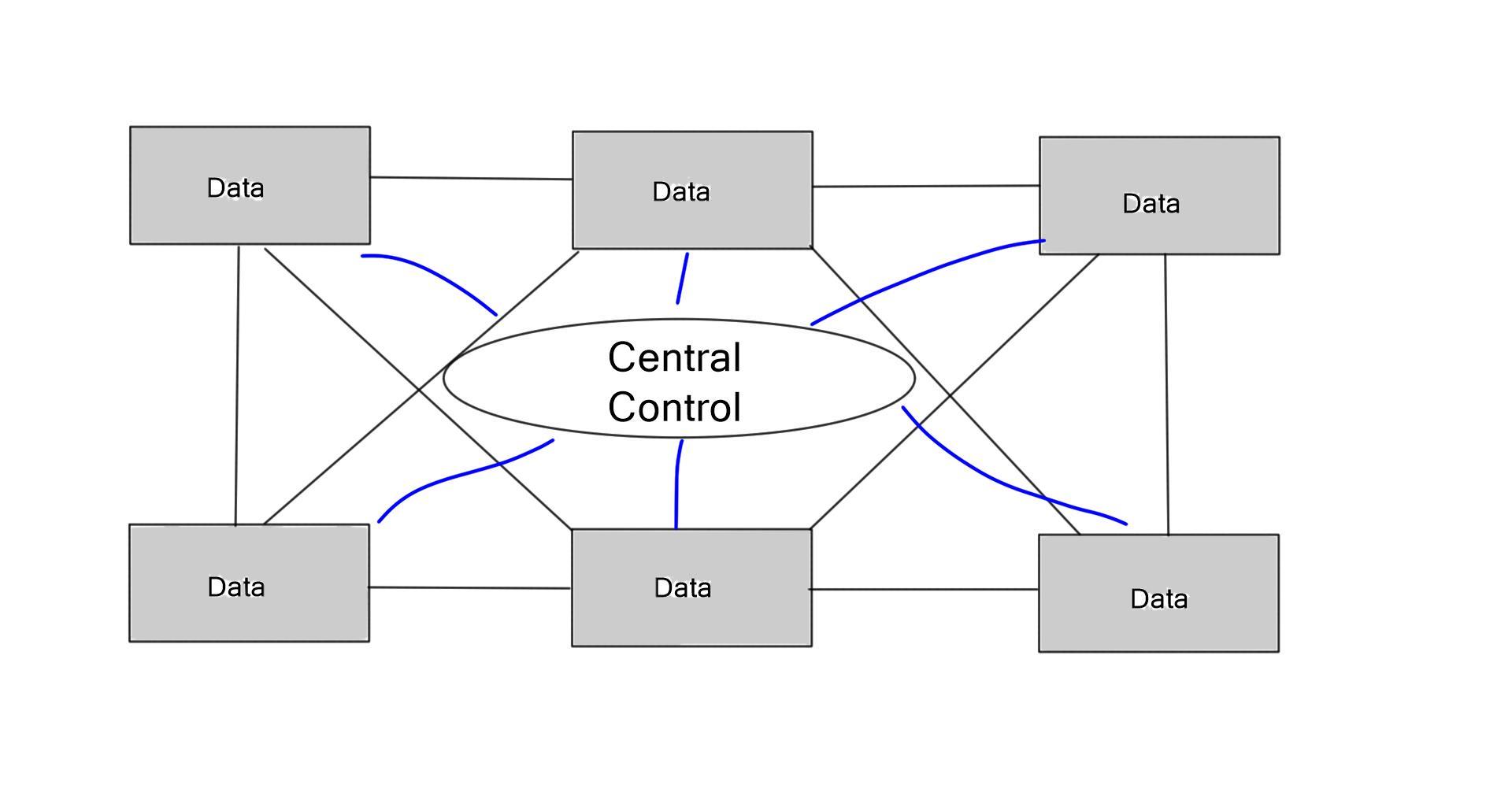
OpenFlow can be best described as a protocol that enables the separation of the control plane and the data plane in a network. Traditionally, network devices handled both the control and data forwarding aspects, leading to limited flexibility and scalability. With OpenFlow, the control plane is centralized in a controller, allowing for dynamic network management and programmability.

Benefits of OpenFlow: The adoption of OpenFlow brings forth a multitude of benefits. Firstly, it offers network administrators unprecedented control and visibility into the network, empowering them to efficiently manage traffic flows and implement changes on the fly. Additionally, OpenFlow promotes network programmability, enabling the development of innovative applications and services that can harness the full potential of the network infrastructure.

OpenFlow in Action: Numerous organizations and industries have recognized the potential of OpenFlow and have embraced it in their networks. For instance, data centers have leveraged OpenFlow to create virtual networks with enhanced security and improved resource allocation. Internet Service Providers (ISPs) have also adopted OpenFlow to optimize traffic routing and enhance network performance.

Challenges and Considerations: While OpenFlow holds great promise, it is not without its challenges. One of the primary concerns is ensuring interoperability across different vendors and devices, as OpenFlow relies on a standard set of protocols and features. Additionally, network security and policy enforcement must be carefully addressed to prevent unauthorized access and protect sensitive data.

OpenFlow and SDN adoption are revolutionizing the networking industry, offering unprecedented control, programmability, and scalability. As organizations continue to recognize the benefits of OpenFlow, we can expect to see further advancements and innovations in the realm of network management and infrastructure.

Highlights: OpenFlow and SDN Adoption

Understanding OpenFlow

OpenFlow is a communication protocol that enables the separation of the control plane and the data plane in network switches. By doing so, it allows for centralized control and programmability of network devices. This revolutionary approach replaces traditional, fixed-function network devices with programmable switches, enabling more flexibility and agility in network management.

SDN provides network administrators with a holistic view of the network, allowing them to monitor and manage network traffic with granular control. This increased visibility enables better troubleshooting, efficient resource allocation, and improved security measures.

**Simplified Network Management**

With SDN, network configurations can be abstracted and managed through software, eliminating the need for manual, device-by-device configuration changes. This simplification streamlines network management, reduces human errors, and accelerates network provisioning and deployment.

The programmability of SDN allows for dynamic network provisioning and scaling, making it easier to adapt to changing network demands. Whether it’s scaling up to accommodate increased traffic or reconfiguring network paths, SDN offers unparalleled flexibility, enabling networks to evolve and grow seamlessly.

**SDN & Virtualization**

SDN opens doors to network virtualization, where multiple virtual networks can coexist on a shared physical network infrastructure. This concept enables efficient resource utilization, isolation of traffic, and improved network efficiency.

By decoupling the control plane from the data plane, SDN fosters an environment for experimentation and innovation. Developers can create and deploy custom network applications, allowing for rapid prototyping and testing of new networking concepts without disrupting the underlying infrastructure.

 **Basics of Network Virtualization**

Network virtualization involves creating a virtual network that operates independently of the underlying physical hardware. This is achieved through software-defined networking (SDN) and network functions virtualization (NFV). SDN separates the network’s control plane from the data plane, allowing for centralized management and control of network traffic. NFV, on the other hand, replaces traditional network hardware functions with software-based solutions, enabling greater flexibility and scalability.

Use Cases and Real-World Applications

A: -) OpenFlow and SDN have been found to be extensively used in various domains and industries. From data centers and cloud computing environments to enterprise networks and even telecommunications, the versatility of OpenFlow and SDN is undeniable.

B: -) They enable dynamic traffic engineering, efficient load balancing, and improved network security. Furthermore, SDN has paved the way for network function virtualization (NFV), allowing the deployment of network services as software applications rather than dedicated hardware.

Background: OpenFlow L2 Switching & VLAN Handling

Layer 2 OpenFlow switching relies on a structured pipeline where packets enter Table 0 for initial classification and then move to Table 1 for forwarding. VLAN tags play a central role in segmenting traffic, and actions such as push_vlan, pop_vlan, and set_vlan_id allow the pipeline to add, remove, or rewrite VLAN identifiers as packets traverse the network. This lab demonstrates how VLAN-aware forwarding behaves inside an SDN-driven LAN.

When a packet arrives, the switch evaluates its fields—source MAC, destination MAC, and VLAN ID—against the flow entries in each table. If a match exists, the associated actions are applied, modifying the VLAN tag or directing the packet to the correct output port. If no match is found, the packet is surfaced for further processing, allowing new flow entries to be added dynamically. This mechanism ensures the pipeline adapts to traffic patterns and VLAN requirements.

The three test cases highlight different aspects of VLAN manipulation within the OpenFlow pipeline. Test 1 shows VLAN retagging, where traffic arriving on VLAN 10 is processed and forwarded using VLAN 20. Test 2 demonstrates VLAN removal, with VLAN 30 traffic being stripped and delivered as an untagged frame. Test 3 illustrates VLAN rewriting, where an unknown VLAN 999 is converted into VLAN 20 to maintain consistent segmentation across the forwarding path.

These tests collectively show how flexible VLAN handling enables predictable forwarding in SDN-based LANs. By retagging, removing, or rewriting VLANs, the pipeline ensures that hosts receive traffic in the correct segment regardless of how packets enter the network. This approach eliminates reliance on traditional MAC learning and provides deterministic, rule-driven forwarding that scales cleanly across multi-switch topologies.

Impact on the Networking Landscape

– At its core, OpenFlow is a communications protocol that enables the separation of the control plane and the data plane in networking devices. It allows for the programmability and centralized control of network switches and routers. With OpenFlow, network administrators can dynamically manage traffic, define routing paths, and apply policies, all through a centralized controller.

– SDN takes the concept of OpenFlow further by providing a framework for network management and configuration. It abstracts the underlying network infrastructure and allows for programmability and automation through a software-based controller. SDN architectures offer flexibility, scalability, and agility, making adapting to evolving network demands easier.

– The combination of OpenFlow and SDN brings numerous benefits to network operators, administrators, and end-users. Firstly, it simplifies network management by providing a centralized view and control of the entire network.

– This simplification leads to enhanced network visibility, easier troubleshooting, and faster deployment of new services. Additionally, OpenFlow and SDN enable network virtualization, allowing for the creation of logical networks decoupled from the physical infrastructure.

The SDN Layers

The Application Layer:

As its name suggests, this layer includes network applications. Examples of these applications include communication applications, such as VoIP prioritization, and security applications, such as firewalls. Also included in this layer are utilities and network services.

Switches and routers traditionally handled these applications. SDN simplifies their management by offloading them. In addition, companies can save a lot of money by stripping down the hardware.

The Control Layer:

Switches and routers are now controlled by a centralized control plane, which allows the network to be programmed. As an open-source network protocol, OpenFlow has become the industry standard despite Cisco’s OpenFlow variant.

The Infrastructure Layer:

This layer includes data, switches, and routers. Traffic is moved according to flow tables. SDN leaves this layer essentially unchanged since routers and switches still move packets. The main difference is the centralization of traffic flow rules. However, the intelligence of vendor devices is not stripped away.

The API provides centralized control of SDN for large network providers to protect their intellectual property. However, the cost of generic packet-forwarding devices is much lower than traditional networking equipment.

SDN and OpenFlow

A Programmable Network

Developers have made it possible for network administrators to create “slices” that allow generic networking hardware to support multiple configurations by adding a virtualization layer between the control system and the hardware layer. It resembles how a hypervisor can run a virtual machine (VM) on a single server. Using SDN, an administrator can create different rules and applications for various groups of users.

Because most applications are not installed on the devices, SDN enables the network to appear as one big switch/router. There could be three devices on the network or 30,000. They are all the same as centralized applications. (Some applications are just nodes on the network.) Therefore, upgrades, changes, additions, and configurations are much more accessible.

The role of OpenFlow

Firstly, the basis of the SDN adoption report is the OpenFlow protocol, an existing technology derived from academic labs. Its origins can be traced back to 2006 when Martin Casado, part of the “Clean Slate” program, developed Ethane. They were trying to figure out ways to manage the network states via a centrally managed global policy.

The idea that networks are dynamic and non-symmetrical poses challenges in keeping track of their state to enforce programmability. The program has stopped but produced several follow-up programs, including OpenFlow and SDN.

SDN OpenFlow is not revolutionary new. Similar ideas have been available, and previous projects have tried to solve the same problems OpenFlow is trying to solve today. Besides the central viewpoint use case, whatever you can do with OpenFlow today is possible with Policy-Based Routing (PBR) and ACL. The problem is that these tools are clumsy and do not scale well.

What is OpenFlow

You may find the following useful for pre-information:

  1. Virtual Overlay Network
  2. SDN Router
  3. What is OpenFlow
  4. BGP SDN
  5. SDN BGP
  6. Hyperscale Networking
  7. SDN Data Center

OpenFlow and SDN Adoption

What is OpenFlow?

OpenFlow is an open standard that enables the separation of the control plane and the data plane in network devices. It allows network administrators to centrally control and manage the behavior of network switches and routers, resulting in increased network programmability, flexibility, and scalability. OpenFlow provides a standardized protocol that facilitates communication between the control and data planes, enabling the network to be programmed and controlled through software.

Understanding SDN Adoption:

SDN is a paradigm shift in network architecture that leverages OpenFlow and other technologies to virtualize and abstract network resources. With SDN, the control plane is decoupled from the underlying physical infrastructure, allowing network administrators to configure and manage networks dynamically through a centralized controller. This centralized control simplifies network operations, enhances automation, and creates innovative network services.

The use of APIs:

Besides the network abstraction, the SDN architecture will deliver a set of APIs that streamline the implementation of standard network services. These network services include routing, security, access control, and traffic engineering. Consequently, we can achieve exceptional programmability, automation, and network control, enabling us to build highly scalable and flexible networks that readily adapt to changing business needs. Then, we have OpenFlow and the SDN story. OpenFlow is the first standard interface explicitly designed for SDN, providing high-performance and granular traffic control across multiple networking devices.

**Benefits of OpenFlow and SDN Adoption**

The adoption of OpenFlow and SDN comes with numerous benefits for organizations of all sizes:

1. Enhanced Network Programmability: OpenFlow and SDN enable network administrators to program and control networks through software, making implementing new network services and policies easier.

2. Increased Flexibility and Scalability: SDN allows for dynamic network reconfiguration and resource allocation, ensuring networks can adapt to changing requirements and scale efficiently.

3. Centralized Network Management: With SDN, network administrators can manage and configure multiple network devices from a centralized controller, simplifying network operations and reducing the complexity of managing traditional networks.

4. Improved Network Security: SDN facilitates the implementation of granular security policies, enabling network administrators to quickly detect and respond to security threats, enhancing overall network security.

**Challenges and Considerations**

While OpenFlow and SDN offer significant advantages, their adoption comes with a few challenges that organizations need to address:

1. Compatibility: Not all network devices and vendors fully support OpenFlow and SDN, requiring organizations to consider device compatibility carefully before implementation.

2. Skillset and Training: SDN introduces new concepts and requires network administrators to acquire skills and knowledge to deploy and manage SDN-based networks effectively.

3. Transition from Legacy Infrastructure: Migrating from traditional networking solutions to SDN-based architectures requires careful planning and a phased approach to minimize disruptions and ensure a smooth transition.

Starting Points for SDN Adoption

SDN Architectures and OpenFlow

SDN architectures and OpenFlow offer several advantages. You can influence traffic forwarding behavior at a more granular flow level. A holistic view instead of a partial view of distributed devices simplifies the network. Traffic engineering with SDN becomes easier to implement when you have a centralized view; this is how Google implemented SDN. Google has two network backbones: an Internet-facing backbone and a data center backbone. 

They noticed that the cost/bit was not decreasing as the network grew. It was doing the opposite. Their solution was to implement a centralized controller and manage the WAN as a fabric, not as a collection of individual nodes.

SDN adoption report: Virtual switching fabric

SDN architectures allow networks to move from loosely coupled systems to a virtual switching fabric. One extensive flat virtualized network that appears and can be managed as a single switch has many operational advantages. The switch fabric consists of multiple physical nodes but behaves like one big switch. For example, a port on any underlying switch fabric nodes or virtual switch appears as a port to the single switching fabric.

The entire data plane becomes an abstraction. By employing this architecture, we manage the data plane as a whole entity instead of a set of loosely coupled connected devices. If we study existing networks, the control and data planes are distributed to the same locations. No central point controls individual nodes, resulting in complex cross-network interactions.

sdn adoption

Open Shortest Path First (OSPF)

Open Shortest Path First (OSPF) calculates the shortest path tree from each node to every other node. Each OSPF neighbor must establish an adjacency and build and synchronize the link-state databases (LSB). The complexity can be reduced by designing OSPF areas with ABRs but by sacrificing some precision of route information. Imagine that every node reports and synchronizes its LSB to a central controller with an OSPF SDN application instead of individual nodes.

The controller can perform the Shortest Path First (SPF) calculation and directly update each node’s forwarding information base (FIB). The network now becomes programmable. While it does bring advantages, the laws of physics have not changed.

OpenFlow does not decrease latency or let you push more bits through a link. It does, however, let you better manage and control your network. It removes the box-by-box mentality and introduces automation and programmability.

SDN CONTROLLERExample Routing Technology with OSPF

#### Introduction to OSPFv3

In the realm of networking, efficient and reliable routing protocols are crucial for ensuring seamless data transmission. One such protocol that has gained prominence is OSPFv3 (Open Shortest Path First version 3). This blog post will delve into the intricacies of OSPFv3, exploring its features, benefits, and the role it plays in modern networks.

#### Understanding OSPFv3 Basics

OSPFv3 is an evolution of the OSPF protocol, specifically designed to support IPv6. While it retains the core functionalities of its predecessor, OSPFv2, OSPFv3 brings enhancements that make it more suitable for IPv6-based networks. Unlike OSPFv2, which operates at the network layer, OSPFv3 is designed to work with both IPv4 and IPv6, offering greater flexibility and future-proofing networks as organizations transition to IPv6.

#### Key Features of OSPFv3

One of the standout features of OSPFv3 is its capability to support multiple instances per link. This means that different OSPFv3 processes can operate over the same network link, providing advanced network segmentation and improved routing efficiency. Additionally, OSPFv3 introduces a simplified header format, reducing overhead and enhancing performance. The protocol also supports address families, allowing for more granular control over routing decisions.

#### OSPFv3 vs. OSPFv2: What’s the Difference?

While OSPFv2 and OSPFv3 share a common heritage, there are notable differences between them. OSPFv3’s support for IPv6 is the most significant distinction, but it also includes changes in LSA (Link State Advertisement) types and packet structures. Furthermore, OSPFv3 operates with a more modular approach, separating topology information from routing information, thereby improving scalability and efficiency in complex network environments.


Do you think OpenFlow will be derailed?

SDN OpenFlow has come up against some market adoption barriers, such as silicon challenges and numerous vendor-specific extensions. In addition, the lack of conformance tests has led to some inconsistencies. It depends on how you define it. To explain it, you need to know what it is not. It is not a controller or a forwarding switch but a communication between the two.

It has a distinct place in the SDN architecture and does not run anywhere except between the control (controller) and the data plane, such as the OVS bridge acting as the switch infrastructure. SDN OpenFlow is also not alone in this space; other technologies provide control and data plane communications, such as BGP, Open vSwitch Database Management Protocol (OVSDB), NETCONF, and Extensible Message and Presence Protocol (XMPP).

Juniper’s OpenContrail uses XMPP.

SDN ADOPTION

It is evolving, and emerging technologies are sometimes slow to adopt. For example, in the early days of Novell networks, there were 4-frame types. Likewise, OpenFlow is changing and adapting as time progresses. For example, the original version of OpenFlow did not have multiple flow tables; now, versions 1.3 and 1.4 have multiple tables with various actions and many additional features.

**Will it be used for program forwarding paths instead of BGP?** 

Probably not, but it will augment BGP and other traditional technologies. It is not strictly a YES or NO answer as the SDN adoption falls into two buckets: one with OpenFlow and one without. Take the IPv6 adaptations as the IPv4 “replacement.” There was a “D” day of IPv4 address exhaustion, but IPv4 is still widely used. New “transition” mechanisms such as 6to4 and NAT64 are still widely deployed. It is the same with SDN and OpenFlow.

Example IPv6 Technology: NAT64

**How NAT64 Works**

NAT64, short for Network Address Translation from IPv6 to IPv4, acts as a translator between IPv6 and IPv4. It allows IPv6 clients to access IPv4 services by translating IPv6 addresses into IPv4 addresses and vice versa. This is achieved through a NAT64 gateway, which facilitates the exchange of data between the two different protocols. The gateway assigns an IPv6 prefix for the IPv4 address pool, enabling seamless communication across the network. Understanding this process is vital for network administrators tasked with managing hybrid networks during the transition phase.

**Benefits of Implementing NAT64**

Implementing NAT64 offers numerous benefits for organizations and network administrators. Firstly, it aids in the gradual transition to IPv6 by allowing IPv6-only devices to access IPv4 content. This is particularly beneficial for mobile networks and new internet service providers aiming to future-proof their infrastructure. Additionally, NAT64 reduces the need for dual-stack configurations, which can be complex and resource-intensive. By simplifying network configurations, NAT64 helps cut operational costs and streamline network management.

There will be ways to make traditional networks communicate with SDN and OpenFlow. BGP was invented as an EBGP, but people use EBGP Internal in their network. BGP is also used as an SDN control plane. It will be the case that you have controllers that provide automation and a holistic view but can speak BGP or OSPF to program the forwarding devices. SDN migrations will come incrementally, similar to what we see with IPv4 and IPv6

The lack of clarity in the controller space has limited OpenFlow’s progress. However, the controller market is consolidating now, which gives users a clear path forward. This emergence is a good thing and will move OpenFlow forward. Maintaining SDN applications on different controllers is a dead end, but now that OpenDaylight is emerging, we have controller unity.

A market with numerous open-source controllers would make SDN application development difficult. There will always be business drivers for proprietary controllers serving a particular niche and corner case problems the open community did not invest in. Even today, specialized UNIX platforms exist when you look at open Linux. Similarly, this adoption of technology will be evident for OpenFlow controllers.

Example BGP Technology: EBGP and IBGP

### Understanding BGP: The Basics

Before diving into the preferences, it’s crucial to understand what BGP is. Border Gateway Protocol (BGP) is a standardized exterior gateway protocol designed to exchange routing and reachability information among autonomous systems (AS) on the internet. It is key to ensuring data finds the most efficient path across the complex web of networks.

– **eBGP vs. iBGP:** eBGP is used for communication between different autonomous systems, while iBGP is used within the same autonomous system. This distinction is fundamental in understanding their roles and why eBGP is often preferred.

### The Preference for eBGP: Key Reasons

1. **Policy Control and Flexibility:** eBGP allows for more granular policy control, enabling network administrators to implement routing policies that align with business objectives. This flexibility is less pronounced in iBGP, which is typically used to propagate routes within an AS.

2. **Route Propagation and Stability:** eBGP sessions are generally between routers in different administrative domains, which inherently adds a layer of stability and security in route propagation. eBGP routes are often considered more reliable due to the distinct boundaries they operate across.

3. **Loop Prevention Mechanics:** eBGP inherently prevents routing loops by default, due to its AS-path attribute which records the path that routing information has traversed. iBGP requires additional mechanisms, such as route reflectors or confederations, to handle loop prevention efficiently.

### Practical Implications for Network Administrators

Understanding the preference for eBGP over iBGP can significantly impact how network administrators design and manage networks. For instance, leveraging eBGP for inter-AS communication can lead to more robust and secure network architectures. Additionally, the ability to set preferences for route selection can optimize traffic flow and enhance network performance.

The Future of OpenFlow and SDN:

The adoption of OpenFlow and SDN has gained significant momentum in recent years, and the future looks promising for these technologies. With the increasing demand for flexible, scalable, and programmable networks, OpenFlow and SDN are vital in deploying 5G networks, Internet of Things (IoT) applications, and network virtualization.

OpenFlow and SDN adoption revolutionizes network infrastructure, offering increased programmability, flexibility, and centralized management. While challenges exist, the benefits of OpenFlow and SDN far outweigh the drawbacks.

As organizations continue to embrace digital transformation, OpenFlow and SDN will continue to shape the future of networking, enabling agile, scalable, and secure networks that can adapt to the evolving needs of modern businesses.

Closing Points on SDN and OpenFlow

In the realm of modern networking, OpenFlow and Software-Defined Networking (SDN) stand as pioneers of a transformative journey. Traditional networks, often rigid and complex, are evolving into more dynamic and programmable entities, thanks to these groundbreaking technologies. OpenFlow, a protocol that enables the separation of the control and data planes, is at the heart of this transformation. Combined with SDN, which offers centralized control over network devices, organizations can now manage their networks with unprecedented flexibility and efficiency.

Adopting OpenFlow and SDN brings a plethora of advantages. First and foremost, network administrators gain enhanced control and visibility over their entire network infrastructure. This centralized management simplifies the deployment of new services and reduces the time needed for troubleshooting. Additionally, the programmability of SDN allows for rapid adaptation to changing business needs, providing a competitive edge in today’s fast-paced digital landscape. Cost savings are another major benefit, as organizations can optimize resource usage and reduce hardware dependency.

While the benefits are clear, the road to adopting OpenFlow and SDN is not without its challenges. One of the primary obstacles is the need for a shift in mindset. Network engineers accustomed to traditional methods must embrace new skills and paradigms. There is also the challenge of interoperability, as integrating OpenFlow and SDN with existing systems can be complex. Security concerns, too, must be addressed, as the centralized nature of SDN can introduce new vulnerabilities if not properly managed.

Despite the challenges, many organizations have successfully adopted OpenFlow and SDN. For instance, large data centers and cloud service providers have leveraged these technologies to enhance scalability and performance. In the telecommunications sector, companies have implemented SDN to improve network traffic management and service delivery. These success stories illustrate the transformative potential of OpenFlow and SDN, providing a blueprint for others to follow.

Summary: OpenFlow and SDN Adoption

In today’s rapidly evolving technological landscape, Software-Defined Networking (SDN) and OpenFlow have emerged as game-changing innovations revolutionizing the world of networking. This blog post delves into the intricacies of SDN and OpenFlow, exploring their capabilities, benefits, and their potential to reshape the future of networking.

Understanding SDN

SDN, short for Software-Defined Networking, is a paradigm that separates the control plane from the data plane, enabling centralized network management. Unlike traditional networking approaches, SDN decouples network control, making it programmable and agile. It empowers network administrators with unprecedented flexibility and control over their infrastructure. 

Unveiling OpenFlow

At the core of SDN lies OpenFlow, a protocol that enables communication between the control and data planes. OpenFlow facilitates the flow of network packets, allowing administrators to define and manage network traffic dynamically. Providing a standardized interface promotes interoperability between different vendors’ networking equipment, fostering innovation and cost-effectiveness. 

Benefits of SDN and OpenFlow

Enhanced Network Flexibility and Scalability: SDN and OpenFlow enable network administrators to adjust network resources dynamically, optimize traffic flow, and respond to changing demands. This flexibility and scalability empower organizations to adapt swiftly to evolving network requirements, ensuring efficient resource utilization. 

Simplified Network Management: With SDN and OpenFlow, network administrators can centrally manage and orchestrate network devices, eliminating the need for manual configurations on individual devices. This centralized control simplifies network management, reduces human errors, and accelerates the deployment of new services. 

Improved Network Security: SDN’s centralized control allows for better security management. Administrators gain granular control over network access, threat detection, and response by implementing security policies and protocols at the controller level. This enhanced security posture helps safeguard critical assets and data. 

Data Center Networking: SDN and OpenFlow find extensive applications in data centers, where virtualization and cloud computing demand dynamic resource allocation and efficient traffic management. By abstracting network control, SDN facilitates seamless scalability, load balancing, and efficient utilization of data center resources.  

Campus and Enterprise Networks: In campus and enterprise networks, SDN and OpenFlow enable administrators to manage and optimize network traffic, prioritize critical applications, and quickly respond to changing user demands. These technologies also facilitate network slicing, allowing organizations to create virtual networks tailored to specific requirements. 

In conclusion, SDN and OpenFlow represent a paradigm shift in networking, offering immense potential for increased efficiency, scalability, and security. As organizations continue to embrace digital transformation, these technologies will play a pivotal role in shaping the future of networking. By decoupling network control and leveraging the power of programmability, SDN and OpenFlow empower administrators to build agile, intelligent, and future-ready networks.

OpenStack written on the keyboard button

Openstack Architecture in Cloud Computing

OpenStack Architecture in Cloud Computing

Cloud computing has revolutionized businesses' operations by providing flexible and scalable infrastructure for hosting applications and storing data. OpenStack, an open-source cloud computing platform, has gained significant popularity due to its robust architecture and comprehensive services.

In this blog post, we will explore the architecture of OpenStack and how it enables organizations to build and manage their own private or public clouds.

At its core, OpenStack comprises several interconnected components, each serving a specific purpose in the cloud infrastructure. The architecture follows a modular approach, allowing users to select and integrate the components that best fit their requirements.

OpenStack architecture is designed to be modular and scalable, allowing businesses to build and manage their own private or public clouds. At its core, OpenStack consists of several key components, including Nova, Neutron, Cinder, Glance, and Keystone. Each component serves a specific purpose, such as compute, networking, storage, image management, and identity management, respectively.

Highlights: OpenStack Architecture in Cloud Computing

Understanding OpenStack Architecture

OpenStack is an open-source cloud computing platform that allows users to build and manage cloud environments. At its core, OpenStack consists of several key components, including Nova, Neutron, Cinder, Glance, and Keystone. Each component plays a crucial role in the overall architecture, working together seamlessly to deliver a comprehensive cloud infrastructure solution.

**Core Components of OpenStack**

OpenStack is composed of several interrelated components, each serving a specific function to create a comprehensive cloud environment. At its heart lies the Nova service, which orchestrates the compute resources, allowing users to manage virtual machines and other instances.

Swift, another key component, provides scalable object storage, ensuring data is securely stored and easily accessible. Meanwhile, Neutron takes care of networking, offering a rich set of services to manage connectivity and security across the cloud infrastructure. Together, these components and others such as Cinder for block storage and Horizon for the dashboard interface, form a cohesive cloud ecosystem.

**The Benefits of OpenStack**

What makes OpenStack particularly appealing to organizations is its open-source nature, which translates to cost savings and flexibility. Without the constraints of vendor lock-in, businesses can tailor their cloud infrastructure to meet specific requirements, integrating a wide array of tools and services.

OpenStack also boasts a robust community of developers and users who contribute to its continual improvement, ensuring it remains at the forefront of cloud innovation. Its ability to scale effortlessly as an organization grows is another significant advantage, providing the agility needed in today’s fast-paced business environment.

**Why Businesses Choose OpenStack**

Businesses across various sectors are adopting OpenStack to leverage its versatility and power. Whether it’s a tech startup looking to rapidly scale operations or an established enterprise seeking to optimize its IT resources, OpenStack provides the infrastructure needed to support diverse workloads. Its compatibility with popular cloud-native technologies like Kubernetes further enhances its appeal, enabling seamless integration with modern development practices. By choosing OpenStack, organizations are equipped to tackle the challenges of digital transformation head-on.

1: – Nova – The Compute Service

Nova, the compute service in OpenStack, is responsible for managing and orchestrating virtual machines (VMs). It provides the necessary APIs and services to launch, schedule, and monitor instances. Nova ensures efficient resource allocation, enabling users to scale their compute resources as needed.

2: – Neutron – The Networking Service

Neutron is the networking service in OpenStack that handles network connectivity and addresses. It allows users to create and manage virtual networks, routers, and firewalls. Neutron’s flexibility and extensibility make it a crucial component for building complex network topologies within the OpenStack environment.

3: – Cinder – The Block Storage Service

Cinder provides block storage services in OpenStack, allowing users to attach and manage persistent storage volumes. It offers features like snapshots and cloning, enabling data consistency and efficient storage management. Cinder integrates with various storage technologies, providing flexibility and scalability in meeting different storage requirements.

4: – Glance – The Image Service

Glance acts as the image service in OpenStack, providing a repository for managing virtual machine images. It allows users to store, discover, and retrieve images, simplifying the process of deploying new instances. Glance supports multiple image formats and can integrate with various storage backends, offering versatility in image management.

Keystone – The Identity Service

Keystone serves as the identity service in OpenStack, handling user authentication and authorization. It provides a centralized authentication mechanism, enabling secure access to the OpenStack environment. Keystone integrates with existing identity providers, simplifying user management for administrators.

What is OpenStack?

OpenStack is a comprehensive cloud computing platform that enables the creation and management of private and public clouds. It provides interrelated services, including computing, storage, networking, and more. OpenStack’s open-source nature fosters collaboration and innovation within the cloud community.

Cloud computing platforms such as OpenStack are free and open standards. Both public and private clouds use infrastructure-as-a-service (IaaS) to provide users with virtual servers and other resources. In a data center, a software platform controls diverse, multi-vendor pools of processing, storage, and networking resources. In addition to web-based dashboards, command-line tools, and RESTful web services are available to manage them.

NASA and Rackspace Hosting began developing OpenStack in 2010. The OpenStack Foundation, a non-profit corporation established in September 2012[3] to promote OpenStack software and its community, managed the project as of 2012. In 2021, the foundation announced it would be renamed the Open Infrastructure Foundation. By 2018, more than 500 companies had joined the project.

**Key Features of OpenStack**

OpenStack offers a wide range of features, making it a powerful and flexible cloud solution. Some of its notable features include:

1. Scalability and Elasticity: OpenStack allows users to scale their infrastructure up or down based on demand, ensuring optimal resource utilization.

2. Multi-Tenancy: With OpenStack, multiple users or organizations can securely share the same cloud infrastructure while maintaining isolation and privacy.

3. Modular Architecture: OpenStack’s modular design allows users to choose and integrate specific components per their requirements, providing a highly customizable cloud environment.

OpenStack: The cloud operation system

– Cloud operating systems such as OpenStack are best viewed as public and private clouds, respectively. In this era of cloud computing, we are moving away from virtualization and software-defined networking (SDN). Any organization can build a cloud infrastructure using OpenStack without committing to a vendor.

– Despite being open source, OpenStack has the support of many heavyweights in the industry, such as Rackspace, Cisco, VMware, EMC, Dell, HP, Red Hat, and IBM. If a brand name acquires OpenStack, it won’t disappear overnight or lose its open-source status.

– OpenStack is also an application and toolset that provides identity management, orchestration, and metering. Despite supporting several hypervisors, such as VMware ESXi, KVM, Xen, and Hyper-V, OpenStack is not a hypervisor. Thus, OpenStack does not replace these hypervisors; it is not a virtualization platform but a cloud management platform.

– OpenStack is composed of many modular components, each of which is governed by a technical committee. OpenStack’s roadmap is determined by a board of directors driven by its community.

Openstack services

OpenStack Modularity

OpenStack is highly modular. Components provide specific services, such as instance management, image catalog management, network management, volume management, object storage, and identity management. A minimal OpenStack deployment can provision instances from images and connect them to networks. Identity management controls cloud access. Some clouds are only used for storage.

There is an object storage component and, again, an identity component. The OpenStack community does not refer to services by their functions, such as services, images, etc. Instead, these components are referred to by their nicknames. Server functions are officially called compute, but everyone calls them Nova. It’s pretty fitting since NASA co-founded OpenStack. Glance is the image service, Neutron is the network service, and Cinder is the volume service. Swift provides object storage, while Keystone includes identity management, which keeps everything together.

The Role of Decoupling

The key to cloud computing is decoupling virtual resources from physical ones. The ability to abstract processors, memory, etc., from the underlying hardware enables on-demand/elastic provisioning and increased efficiency. This abstraction process has driven the cloud and led to various popular cloud flavors such as IaaS – Infrastructure-as-as-Service, PaaS – Platform-as-as-Service, and SaaS – Software-as-as-Service, a base for OpenStack foundations.

The fundamentals have changed, and the emerging way of consuming I.T. ( compute, network, storage ) is the new “O.S.” for the data center in the cloud. The cloud cannot operate automatically and needs a management suite to control and deploy service-oriented infrastructures. Different companies deploy different teams that specialize only in managing cloud computing. Those without an in-house team get it outsourced by firms like Global Storage. 

SDN Abstraction

These platforms rely on a new networking architecture known as software-defined networking. Traditional networking relies on manual administration, and its culture is based on a manual approach. Networking gear is managed box by box, and administrators maintain singular physical network hardware and connectivity. SDN, on the other hand, abstracts the network.

The switching infrastructure may still contain physical switch components but is managed like one switch. The data plane is operated as an entire entity rather than a loosely coupled connected device. SDN approach is often regarded as a prerequisite and necessary foundation for scalable cloud computing.

SDN and OpenFlow

Related: You may find the following post of interest:

  1. OpenStack Neutron Security Groups
  2. OpenStack Neutron
  3. Network Security Components
  4. Hyperscale Networking

OpenStack Architecture in Cloud Computing

The adoption of cloud technology has transformed how companies run their IT services. By leveraging new strategies for resource use, several cloud solutions came into play with different categories: private, public, hybrid, and community. OpenStack falls into the private cloud category. However, deploying OpenStack is still tricky, requiring a good understanding of its beneficial returns to a given organization regarding automation, orchestration, and flexibility.

The New Data Center Paradigm

n cloud computing, infrastructure services such as Software as a Service (SaaS), Platform as a Service (PaaS), and Infrastructure as a Service (IaaS) are provided. Agility, speed, and self-service are the challenges the public cloud sets. Most companies have expensive IT systems, which they have developed and deployed over the years, but these systems are siloed and require human intervention.

As public cloud services become more agile and faster, IT systems struggle to keep up. Today’s agile service delivery environment may make the traditional data center model and siloed infrastructure unsustainable. To achieve next-generation data center efficiency, enterprise data centers must focus on speed, flexibility, and automation.

Fully Automated Infrastructure

Admins and operators can deploy fully automated infrastructures with a software infrastructure within a minute. Next-generation data centers reduce infrastructure to a single, significant, agile, scalable, and automated unit. The result is an infrastructure that is programmable, scalable, and multi-tenant-aware. In this regard, OpenStack stands out as the next generation of data center operating systems.

Several sizeable global cloud enterprises, such as VMware, Cisco, Juniper, IBM, Red Hat, Rackspace, PayPal, and eBay, have benefited from OpenStack. Many are running a private cloud based on OpenStack in their production environment. Your IT infrastructure should use OpenStack if you wish to be a part of an innovative, winning cloud company.

The main components of OpenStack are:

While different services cater to various needs, they follow a common theme in their design:

  • In OpenStack, Python is used to develop most services, making it easier for them to be developed rapidly.

  • REST APIs are available for all OpenStack services. The APIs are the primary communication interfaces for other services and end users.

  • Different components may be used to implement the OpenStack service. A message queue communicates between the service components and has several advantages, including queuing requests, loose coupling, and load distribution.

1. Nova: Nova is the compute service responsible for managing and provisioning virtual machines (VMs) and other instances. It provides an interface to control and automate the deployment of instances across multiple hypervisors.

2. Neutron: Neutron is a networking service that enables the creation and management of virtual networks within the cloud environment. It offers a range of networking options, including virtual routers, load balancers, and firewalls, allowing users to customize their network configurations.

3. Cinder: Cinder provides block storage to OpenStack instances. It allows users to create and manage persistent storage volumes, which can be attached to cases for data storage. Cinder supports various storage backends, including local disks and network-attached storage (NAS) devices.

4. Swift: Swift is an object storage service that provides scalable and durable storage for unstructured data. It enables users to store and retrieve large amounts of data, making it suitable for applications that require high scalability and fault tolerance.

5. Keystone: Keystone serves as the identity service for OpenStack, providing authentication and authorization mechanisms. It manages user credentials and assigns access rights to the various components and services within the cloud infrastructure.

6. Glance: Glance is an image service that enables users to discover, register, and retrieve virtual machine images. It provides a catalog of images that can be used to launch instances, making it easy to create and manage VM templates.

7. Horizon: Horizon is the web-based dashboard for OpenStack, providing a graphical user interface (GUI) for managing and monitoring the cloud infrastructure. It allows users to perform administrative tasks like launching instances, managing networks, and configuring security settings.

These components work together to provide a comprehensive cloud computing platform that offers scalability, high availability, and efficient resource management. OpenStack’s architecture is designed to be highly modular and extensible, allowing users to add or replace components per their specific requirements.

Keystone

Architecturally, Keystone is the most straightforward service in OpenStack. OpenStack’s core component provides an identity service that enables tenant authentication and authorization. By authorizing communication between OpenStack services, Keystone ensures that the correct user or service can access the requested OpenStack service.

Keystone integrates with numerous authentication mechanisms, including usernames, passwords, tokens, and authentication-based systems. It can also be integrated with existing backends like Lightweight Directory Access Protocol (LDAP) and Pluggable Authentication Module (PAM).

Swift

Swift is one of the storage services that OpenStack users can use. REST APIs provide access to its object-based storage service. Object storage differs from traditional storage solutions, such as file shares and block-based access, in that it treats data as objects that can be stored and retrieved. An overview of Object Storage can be summarized as follows. In the Object Store, data is split into smaller chunks and stored in separate containers. A cluster of storage nodes maintains redundant copies of these containers to provide high availability, auto-recovery, and horizontal scalability.

Cinder

Another way to provide storage to OpenStack users may be to use the Cinder service. This service manages persistent block storage, which provides block-level storage for virtual machines. Virtual machines can use Cinder raw volumes as hard drives.

Some of the features that Cinder offers are as follows:

  • Volume management: This allows the creation or deletion of a volume

  • Snapshot management: This allows the creation or deletion of a snapshot of volumes

  • Attaching or detaching volumes from instances

  • Cloning volumes

  • Creating volumes from snapshots 

  • Copy of images to volumes and vice versa

Like Keystone services, Cinder features can be delivered by orchestrating various backend volume providers, such as IBM, NetApp, Nexenta, and VMware storage products, through configurable drivers.

Manila

As well as the blocks and objects we discussed in the previous section, OpenStack has had a file-share-based storage service called Manila since the Juno release. Storage is provided as a remote file system. Unlike Cinder, it is similar to the Storage Area Network (SAN) service as opposed to the Network File System (NFS) we use on Linux. The Manila service supports NFS, SAMBA, and CIFS as backend drivers. The Manila service orchestrates shares on the share servers.

Glance

An OpenStack user can launch a virtual machine from the Glance service based on images and metadata. Depending on the hypervisor, various image formats are supported. With Glance, you can access images for KVM/Qemu, XEN, VMware, Docker, etc.

When you’re new to OpenStack, you might wonder, What’s the difference between Glance and Swift? Both handle storage. How do they differ? What is the need for such a solution?

Swift is a storage system, whereas Glance is an image registry. In contrast, Glance keeps track of virtual machine images and their associated metadata. Metadata can include kernels, disk images, disk formats, etc. Glance uses REST APIs to make this information available to OpenStack users. Images can be stored in Glance utilizing a variety of backends. Directories are the default approach, but other methods, such as NFS and Swift, can be used in massive production environments.

In contrast, Swift is a storage system. This solution allows you to store data such as virtual disks, images, backup archiving, and more.

As an image registry, Glance serves as a resource for users. Glance focuses on an architectural approach to storing and querying image information via the Image Service API. In contrast, storage systems typically offer highly scalable and redundant data stores, whereas Glance allows users (or external services) to register virtual disk images. You, as a technical operator, must find the right storage solution at this level that is cost-effective and performs well.

**OpenStack Features**

Scalability and Elasticity

OpenStack’s architecture enables seamless scalability and elasticity, allowing businesses to allocate and manage resources dynamically based on their needs. By scaling up or down on demand, organizations can efficiently handle periods of high traffic and optimize resource utilization.

Multi-Tenancy and Isolation

One of OpenStack’s standout features is its robust multi-tenancy support, which enables the creation of isolated environments for different users or projects within a single infrastructure. This ensures enhanced security, privacy, and efficient resource allocation across various departments or clients.

Flexible Deployment Models

OpenStack offers a variety of deployment options, including private, public, and hybrid clouds. This flexibility allows businesses to choose the most suitable model based on their specific requirements, whether maintaining complete control over their infrastructure or leveraging the benefits of public cloud providers.

Comprehensive Service Catalog

With an extensive service catalog, OpenStack provides a wide range of services such as compute, storage, networking, and more. Users can quickly provision and manage these services through a unified dashboard, simplifying the management and deployment of complex infrastructure components.

Open and Vendor-Agnostic

OpenStack’s open-source nature ensures vendor-agnosticism, allowing organizations to choose hardware, software, and services from various vendors. This eliminates the risk of vendor lock-in and fosters a competitive market, driving innovation and cost-effectiveness.

OpenStack Architecture in Cloud Computing

OpenStack Fundations and Origins

OpenStack Foundations is a software platform for orchestrating and automating data center environments. It provides APIs enabling users to create virtual machines, network topologies, and scale applications to business requirements. It does not just let you control your cloud; you may make it available to customers for unique self-service and management.

It’s a collection of projects (each with a specific mission) to create a shared cloud infrastructure maintained by a community. It enables any organization type to build its public or private cloud stack. A key differentiator from OpenStack and other platforms is that it’s open-source, run by an independent community continually updating and reviewing publicly accessible information. The key to its adoption is that customers do not fear vendor lock-in.

The pluggable framework is supported by multiple vendors, allowing customers to move away from the continuous path of yearly software license renewal costs. There is real momentum behind it. The lead-up to OpenStack and cloud computing started with Amazon Web Service (AWS) in 2006. They offered a public IaaS and virtual instances with an API. However, there was no SLA or data guarantee, so research academies mainly used it.

NASA and Rackspace

Historically, OpenStack was founded by NASA and Rackspace. NASA was creating a project called Nebula, which was used for computing. Rackspace was involved in a storage project ( object storage platform ) called Cloud Files. The two projects mentioned above led to a community of collaborating developers working on open projects and components.

There are plenty of vendors behind it and across the entire I.T. stack. For servers, we have Dell and H.P.; Storage consists of NetApp and SolidFire; Networking has Cisco and Software with VMware and IBM.

Initially, OpenStack foundations started with three primary services: NOVA computer service, SWIFT storage service, and GLANCE virtual disk image service. Soon after, many additional services, such as network connectivity, were added. The initial implementations were simple, providing only basic networking via Linux Layer 2 VLANs and IPtables.

Now, with the Neutron networks, you can achieve a variety of advanced topologies and rich network policies. Most networking is based on tunneling ( GRE or VXLAN ). Tunnels are used within the hypervisor, so it fits nicely with multi-tenancy. Tunnels are created between the host over the Layer 3 network within the hypervisor. As a result, tenancy V.M.s can spin up where they want and communicate over the tunnel.

What is an API?

The application programming interface ( API ) is the engine under the cloud hood. The messenger takes requests, tells the systems what you want to do, and then returns the response to you—ultimately creating connectivity.

openstack foundations

Each core project (compute, network, etc.) will expose one or more HTTP/RESTful interfaces for public or managed access. This is known as a Northbound REST API. Northbound API faces some programming interfaces. It conceptualizes lower-level detail functions. Southbound faces the forwarding plane and allows components to communicate with a lower-level part.

For example, a southbound protocol could be OpenFlow or NETCONF. Northbound and southbound are software directions from the reference point of the network operating systems. We now have an East-West interface. At the time of writing, this protocol is not fully standardized, but eventually, it will be used to communicate between federations of controllers for state synchronization and high availability.

Example API Technology: Service Networking API

**Understanding the Basics of Service Networking**

Service Networking APIs primarily serve as the bridge connecting disparate services, allowing them to communicate efficiently. They are designed to simplify the process of integrating services, reducing the complexity associated with managing network connections. On Google Cloud, Service Networking APIs facilitate a variety of use cases, including hybrid cloud setups, service mesh architectures, and microservices communication.

**Key Benefits of Service Networking APIs on Google Cloud**

Google Cloud’s Service Networking APIs offer a plethora of advantages. Firstly, they enhance scalability by allowing services to communicate seamlessly without manual network configurations. Secondly, they bolster security through integrated policies that help safeguard data in transit. Additionally, these APIs support automated service discovery, which significantly reduces the time and effort required for service integrations and deployments.

**Implementing Service Networking APIs**

Implementing Service Networking APIs on Google Cloud is a straightforward process, designed to cater to both novice and experienced developers. Google Cloud provides comprehensive documentation and support, streamlining the setup and configuration of these APIs. Moreover, with tools like Google Kubernetes Engine (GKE) and Anthos, developers can leverage Service Networking APIs to manage and deploy services across hybrid and multi-cloud environments effortlessly.

Service Networking API

OpenStack Architecture: The Foundations

  1. OpenStack Compute – Nova is comparable to AWS EC2. She is used to provisioning instances for applications.
  2. OpenStack Storage – Swift is comparable to AWS S3. Provides object storage functions for application objects.
  3. OpenStack Storage – Cinder is comparable to AWS Elastic Block Storage. Provides persistent block storage functions for stateless instances.
  4. OpenStack Orchestration – Heat is comparable to AWS Cloud formation. Orchestrates deployment of cloud services
  5. OpenStack Networking—Neutron Network is comparable to AWS VPC and ELB. It creates networks, topologies, ports, and routers.

There are others, such as Identity, Image Service, Trove, Ceilometer, and Sahara.

Each OpenStack foundation component has an API that can be called from either CURL, Python, or CLI. CURL is a command-line tool that lets you send HTTP requests and receive responses. Python is a widely used programming language within the OpenStack ecosystem. It automates scripts to create and manage resources in your OpenStack cloud. Finally, command-line interfaces (CLI) can access and send requests to APIs.

OpenStack Architecture & Deployment

OpenStack has a very modular design, and the diagram below displays key OpenStack components. Logically, it can be divided into three groups: a) Control, b) Network, and c) Compute. All of the features use a database or a message bus. The database can either be MySQL, MariaDB, or PostgreSQL. The message bus can be RabbitMQ, Qpid, and ActiveMQ.

The messaging and database could run on the same control node for small or DevOps deployments but could be separated for redundancy. The cloud controller on the left consists of numerous components, which are often disaggregated into separate nodes. It is the logical interface to the cloud and provides the API service.

Openstack Deployment

The network controller includes the networking service Neutron. It offers an API for orchestrating network connectivity. Extension plugins provide additional network services such as VPNs, NAT, security firewalls, and load balancing. Generally, it is separate from the cloud controller, as traffic may flow through it. The compute nodes are the instances. This is where the application instances are deployed. 

Leverage vagrant 

Vagrant is a valuable tool for setting up Dev OpenStack environments to automate and build virtual machines ( with OpenStack ). It’s a wrapper around a virtualization platform, so you are not running the virtualization in Vagrant. The Vagrant V.M. gives you a pure environment to work with as it isolates dependencies from other V.M. applications. Nothing can interfere with the V.M., offering a full testing scope. An excellent place to start is Devstack. It’s the best tool for setting up small single-node non-production/testing installs.

Closing Points: OpenStack Architecture in Cloud Computing 

OpenStack is composed of several core services, each responsible for specific functionalities within the cloud infrastructure. These services include:

– **Nova**: This is the compute service of OpenStack, responsible for managing virtual machines and instances. Nova acts as the brain of the OpenStack ecosystem, ensuring efficient allocation and management of resources.

– **Swift**: OpenStack’s object storage system, Swift, is designed to store and retrieve unstructured data at scale. It ensures data redundancy, scalability, and durability, making it suitable for applications requiring massive storage capabilities.

– **Cinder**: Cinder handles block storage needs, allowing users to manage persistent storage independently of compute instances. This flexibility is essential for applications requiring high-performance storage.

– **Neutron**: Neutron manages networking for OpenStack, providing a framework for users to create and manage networking services like routers, switches, and firewalls.

– **Keystone**: Serving as the identity service, Keystone authenticates and authorizes users and services in an OpenStack environment, ensuring secure access control.

– **Horizon**: This is the dashboard component, allowing users to interact with the OpenStack services through a web-based interface. Horizon offers an intuitive and user-friendly way to manage cloud resources.

One of the key advantages of OpenStack is its ability to scale efficiently. Organizations can start with a small cloud infrastructure and expand it effortlessly as their needs grow. OpenStack’s modular design allows new services to be added without disrupting existing ones, making it an ideal choice for businesses anticipating rapid growth or fluctuating workloads.

Security is paramount in cloud computing, and OpenStack addresses this with a variety of tools and practices. Keystone provides a solid foundation for identity management, while additional security measures are implemented through OpenStack’s extensive community of developers and contributors. Regular updates and compliance checks ensure that OpenStack remains at the forefront of cloud security standards.

Summary: OpenStack Architecture in Cloud Computing

In the fast-evolving world of cloud computing, OpenStack has emerged as a powerful open-source platform that enables efficient management and deployment of cloud infrastructure. Understanding the architecture of OpenStack is essential for developers, administrators, and cloud enthusiasts alike. This blog post delved into the various components and layers of OpenStack architecture, providing a comprehensive overview of its inner workings.

Section 1: OpenStack Components

OpenStack comprises several key components, each serving a specific purpose in the cloud infrastructure. These components include:

1. Nova (Compute Service): Nova is the heart of OpenStack, responsible for managing and provisioning virtual machines (VMs) and controlling compute resources.

2. Neutron (Networking Service): Neutron handles networking functionalities, providing virtual network services, routers, and load balancers.

3. Cinder (Block Storage Service): Cinder offers block storage capabilities, allowing users to attach and manage persistent storage volumes to their instances.

4. Swift (Object Storage Service): Swift provides scalable and durable object storage, ideal for storing large amounts of unstructured data.

Section 2: OpenStack Architecture Layers

The OpenStack architecture is structured into multiple layers, each playing a crucial role in the overall functioning of the platform. These layers include:

1. Infrastructure Layer: This layer comprises the physical hardware resources such as servers, storage devices, and switches that form the foundation of the cloud infrastructure.

2. Control Layer: The control layer comprises services that manage and orchestrate the infrastructure layer. It includes components like Nova, Neutron, and Cinder, which control and coordinate resource allocation and network connectivity.

3. Application Layer: At the topmost layer, the application layer consists of software applications and services that run on the OpenStack infrastructure. These can range from web applications to databases, all utilizing the underlying resources OpenStack provides.

Section 3: OpenStack Deployment Models

OpenStack offers various deployment models to cater to different needs and requirements. These models include:

1. Public Cloud: OpenStack is operated and managed by a third-party service provider in a public cloud deployment, offering cloud services to multiple organizations or individuals over the internet.

2. Private Cloud: A private cloud deployment involves setting up an OpenStack infrastructure exclusively for a single organization. It provides enhanced security and control over data and resources.

3. Hybrid Cloud: A hybrid cloud deployment combines both public and private clouds, allowing organizations to leverage the benefits of both models. This provides flexibility and scalability while ensuring data security and control.

Conclusion

OpenStack architecture is a complex yet robust framework that powers cloud computing environments. Understanding its components, layers, and deployment models is crucial for effectively utilizing and managing OpenStack infrastructure. Whether you are a developer, administrator, or simply curious about cloud computing, exploring OpenStack architecture opens up a world of possibilities for building scalable and efficient cloud environments.

network-automation3

Network Configuration Automation

Network Configuration Automation

In today's fast-paced digital landscape, efficient network configuration automation has become a cornerstone for organizations striving to enhance their operational productivity. Automating network configuration processes not only saves time and effort but also minimizes human error and ensures consistent network performance. In this blog post, we will explore the key benefits and considerations of network configuration automation, along with best practices to implement it effectively.

Network configuration automation refers to the practice of automating the deployment, management, and monitoring of network devices and related configurations. It streamlines the repetitive and time-consuming tasks involved in configuring network devices, such as routers, switches, and firewalls. By utilizing automation tools and frameworks, organizations can achieve greater agility, scalability, and accuracy in their network infrastructure.

Automating network configuration brings numerous advantages to organizations. Firstly, it significantly reduces the risk of human errors that can lead to network downtime or security vulnerabilities. Automation ensures consistency across network devices, eliminating configuration discrepancies.

Secondly, it enhances operational efficiency by reducing manual efforts and standardizing configuration processes, allowing IT teams to focus on more strategic initiatives. Lastly, network configuration automation facilitates faster troubleshooting and enables rapid changes to adapt to dynamic network requirements.

Comprehensive Network Inventory: Begin by creating a detailed inventory of network devices, including their models, firmware versions, and current configurations. This inventory will serve as a foundation for automation workflows.

Define Configuration Standards: Establish clear and standardized configuration templates that align with industry best practices. These templates should include essential parameters, such as IP addresses, routing protocols, and security policies.

Utilize Automation Tools: Choose a robust automation tool or framework that suits your organization's requirements. Evaluate features like device compatibility, scalability, and ease of integration with existing network management systems.

Test and Validate: Before deploying automated configurations in a production environment, thoroughly test and validate them in a controlled lab or staging environment. This step helps identify potential issues or conflicts.

While network configuration automation offers substantial benefits, it is essential to consider potential challenges. Organizations must ensure proper security measures are in place to protect automation tools and the integrity of network configurations. Additionally, regular monitoring and auditing of automated processes are crucial to detect any anomalies or unauthorized changes.

Network configuration automation serves as a catalyst for operational efficiency and reliability in modern network infrastructures. By embracing automation tools, defining robust processes, and adhering to best practices, organizations can streamline their network configuration workflows, reduce errors, and improve overall network performance.

With the right approach, network configuration automation becomes a strategic enabler for organizations seeking to stay competitive in today's digital landscape.

Highlights: Network Configuration Automation

**The Rise of Automation in Networking**

Automation in networking refers to the use of software and technologies to automate the configuration, management, testing, deployment, and operation of network devices. This approach is gaining traction as it addresses some of the most pressing challenges in networking today, such as the need for speed, accuracy, and scalability. By automating routine tasks, network administrators can focus on more strategic initiatives, resulting in more efficient and effective networks.

**Benefits of Networking Automation**

One of the most significant benefits of automation in networking is its ability to enhance efficiency. Automated systems can perform repetitive tasks quickly and accurately, reducing the likelihood of human error. This increased precision leads to improved network performance and reliability. Additionally, automation allows for faster deployment of network changes and updates, enabling organizations to respond swiftly to evolving business needs and technological advancements.

**Overcoming Challenges in Automation**

While the advantages of networking automation are clear, the journey to full automation is not without obstacles. One of the primary challenges is the complexity of integrating automation tools with existing network infrastructures. Organizations must also address potential security issues, as automated systems can be vulnerable to cyber threats if not properly managed. Moreover, there is a need for skilled personnel who can oversee and maintain these automated systems, highlighting the importance of ongoing training and development.

**The Future of Networking: What Lies Ahead?**

As automation continues to gain ground, the future of networking looks promising. Emerging technologies such as artificial intelligence and machine learning are expected to further enhance automation capabilities, leading to more intelligent and adaptive networks. These advancements will enable networks to self-optimize and self-heal, minimizing downtime and maximizing performance. As a result, businesses can expect to see increased efficiency, reduced operational costs, and improved customer satisfaction.

Introducing Network Configuration Automation

1: – In today’s fast-paced digital landscape, efficient network configuration management is crucial for businesses to thrive. Manual network configuration tasks can be time-consuming, error-prone, and hinder productivity. This is where network configuration automation comes into play, revolutionizing the way networks are managed and maintained.

2: – Network configuration automation refers to the use of tools and scripts to automatically configure network devices such as routers, switches, and firewalls. This process eliminates the need for manual configuration, which can be time-consuming and prone to human error. By automating repetitive tasks, organizations can ensure consistency and accuracy across their network infrastructure.

3: – Automating network configuration processes offers a plethora of advantages. Firstly, it significantly reduces human errors that often occur during manual configurations. With automation, consistency and accuracy are ensured, leading to enhanced network reliability. Additionally, network configuration automation saves time and resources, allowing IT teams to focus on more strategic tasks rather than mundane and repetitive configurations.

4: – Implementing network configuration automation involves selecting the right tools and technologies for your organization. Popular options include Ansible, Puppet, and Chef, each offering unique features and capabilities. It’s important to assess your specific needs and environment before choosing a solution. Once implemented, automation scripts can be created and customized to meet your organization’s unique requirements, ensuring seamless integration into existing workflows.

Note: – **Application Changes**

Applications are deployed differently today than they were 10-15 years ago. So much has changed with the app. The problem we are seeing today is that the network is not tightly coupled with these other developments. Providing various network policies and corresponding configurations is not tightly associated with the application.

They are usually loosely coupled and reactive. For example, analyzing firewall rules and providing a network assessment is nearly impossible with old security devices, driving the need for network configuration automation and the ability to automate network configuration.

Right Tools & Strategies 

– To successfully implement network configuration automation, businesses need to adopt the right tools and strategies. Robust automation platforms, such as Ansible or Puppet, can streamline the process by providing intuitive interfaces and extensive libraries of pre-built configurations. IT teams should also establish clear configuration standards and templates to ensure consistency across the network.

– While network configuration automation offers numerous benefits, it’s not without its challenges. One common obstacle is the initial investment required to implement automation tools and train IT staff. However, the long-term cost savings and increased efficiency outweigh the initial costs. Additionally, businesses must carefully plan and test automation workflows to avoid unintended consequences or disruptions to network operations.

Deterministic outcomes

An enterprise organization’s change review involves examining upcoming network changes, their impact on external systems, and their rollback plans. When humans use the CLI to make changes, typing the wrong command can have catastrophic results. Think about a team of three, four, five, or fifty engineers. Depending on the engineer, changes can be made in a variety of ways. In addition, even using a GUI or a CLI does not eliminate or reduce the chance of errors during change control.

The executive team has a better chance of achieving deterministic outcomes when they use proven and tested network automation to make changes. This increases their chances of achieving a successful project the first time around by achieving more predictable behavior than when making changes manually. This might happen when a new VLAN is added or a new customer is onboarded, requiring multiple network changes.

Furthermore, deterministic results result in lower operating expenses (OpEx), as network changes require less manual labor, resulting in a more efficient network operation (e.g., automating time-consuming tasks such as updating a network device’s operating system). Network engineers can focus on more strategic projects and improve processes with less operating time.

Device Provisioning

An easy and fast way to get started with network automation is to automate the creation and pushing of device configuration files. Two steps are involved in this process: creating the configuration file and pushing it to the device.

To automate configuration files (or configuration data in general), the input parameters (configuration parameters) must first be decoupled from the vendor-proprietary syntax (CLI). Separate files will be created for configuration templates, VLANs, domains, interfaces, routing, etc.

Data Collection and Enrichment

Through SNMP, monitoring tools typically poll management information bases (MIBs) for data. Data may be returned in excess or insufficient to meet your needs. What should be done when polling interface statistics? What if you only need interface resets, not CRC errors, jumbo frames, or output errors?

The command show interface may return every counter, but what if you only need interface resets? Moreover, what if you want to see interface resets correlated with Cisco Discovery Protocol (CDP) or LLDP neighbors now rather than in the future? In this context, what role does network automation play?

We focus on giving you more control so you can customize what you get when you get it, how it is formatted, and how it is used after it is collected. Automating the process can maximize your data.

Migrations

Migrating from one platform to another is never easy. There may be platforms from the same vendor or different vendors. In our example, you can create configuration templates for network devices and operating systems using various forms of automation. Vendors may provide a script or tool that helps with migrations. It would then be possible to generate a configuration file for every vendor using a defined and standard data set (common data model).

If you are using them, you must also consider vendor-proprietary extensions. It is fantastic that such a tool can be built independently rather than by a vendor. A vendor must account for all the device features, while an organization only needs a limited number. Vendors aren’t concerned about this; they are worried about their equipment not making it easier for you, the network operator, to manage multivendor environments.

Configuration Management

In configuration management, devices are deployed, pushed, and managed according to their configuration state. Everything from interface descriptions to configurations of ToR switches, firewalls, load balancers, and advanced security infrastructure is covered to deploy three-tier applications.

As you can see, with the read-only forms of automation, you don’t have to start by pushing configurations. This method may be worthwhile if you spend countless hours making the same change across many routers or switches.

Before you proceed, you may find the following articles of interest:

  1. Open Networking
  2. A10 Networks
  3. Brownfield Network Automation

Network Configuration Automation

One of the easiest and quickest ways to get started with network automation is to automate the creation of the device configuration files used for initial device provisioning and push them to network devices. You can also get a lot of information with automation. For example, network devices have enormous static and ephemeral data buried inside, and using open-source tools or building your own gets you access to this data.

Examples of this type of data include entries in the BGP table, OSPF adjacencies, active neighbors, interface statistics, specific counters and resets, and even counters from application-specific integrated circuits (ASICs) themselves on newer platforms.

Guide with Ansible Core

We have Ansible installed and a managed host already prepared in the following. The managed host needs to have SSH enabled and a user with admin privileges. Ansible finds managed hosts by looking at the inventory file. The inventory file is also a great place to pass variables that can be used to remove site-specific information; this is set under the host var section below.

Remember that Ansible requires Python, and below, we are running Python version 3.0.3 and Jinja version 3.0.3, which is used for templating. You can pass information to ansible managed hosts with playbooks and ad hoc commands. Below, I’m using an ad hoc command, calling the command module by default, and testing with a ping.

Ansible configuration
Diagram: Ansible Configuration

**Benefits of Network Configuration Automation**

1. Time and Resource Efficiency: Organizations can free up their IT staff to focus on more strategic initiatives by automating repetitive and time-consuming network configuration tasks. This results in increased productivity and efficiency across the organization.

2. Enhanced Accuracy and Consistency: Manual configuration processes are prone to human error, leading to misconfigurations and network downtime. Network configuration automation eliminates these risks by ensuring consistency and accuracy in network configurations, reducing the chances of costly errors.

3. Rapid Network Deployment: Network administrators can quickly deploy network configurations across multiple devices simultaneously with automation tools. This accelerates network deployment and enables organizations to respond faster to changing business needs.

4. Improved Security and Compliance: Network configuration automation enhances security by enforcing standardized configurations and ensuring compliance with industry regulations. Automated security protocols can be applied consistently across the network, reducing vulnerabilities and enhancing overall network protection.

5. Simplified Network Management: Automation tools provide a centralized platform for managing network configurations, making it easier to monitor, troubleshoot, and maintain network devices. This simplifies network management and reduces the complexity associated with manual configuration processes.

**Implementing Network Configuration Automation**

To implement network configuration automation, organizations need to consider the following steps:

1. Assess Network Requirements: Understand the specific network requirements, including device types, network protocols, and security policies.

2. Select an Automation Tool: Evaluate different automation tools available on the market and choose the one that best suits the organization’s needs and network infrastructure.

3. Create Configuration Templates: Develop standardized configuration templates that can be easily applied to network devices. These templates should include best practices, security policies, and network-specific configurations.

4. Test and Validate: Before deploying automated configurations, thoroughly test and validate them in a controlled environment to ensure their effectiveness and compatibility with the existing network infrastructure.

5. Monitor and Maintain: Regularly monitor and maintain the automated network configurations to identify and resolve any issues or security vulnerabilities that may arise.

The Need to Automate Network Configuration

There are always hundreds, if not thousands, of outdated rules even though the application service is not required. Another example is unused VLANs left configured on access ports, posing a security risk. The problem lies in the process: how we change and provision the network is not tied to the application. It is not automated. Inconsistent configurations tend to grow as human interaction is required to tidy things up. People move on and change roles.

You cannot guarantee the person creating a firewall rule will be the engineer deleting the rule once the corresponding applications are decommissioned or changed. And if you don’t have a rigorous change control process, deprecated configurations will be idle on active nodes.

A key point: The use of Ansible variables in an Ansible architecture.

For configuration management, you could opt for Red Hat Ansible. The Ansible architecture consists of modules with tasks on the target hosts listed in the inventory. Various plugins are available for additional context and Ansible variables for flexible playbook development. Ansible Core is the CLI-based version of automation, and Ansible Tower is the platform.

The recommended approach for enterprise-wide security would be a platform-based approach to the Ansible architecture. Using a platform approach using Ansible variables creates a very flexible automation journey where you can have one playbook with Ansible variables, removing any site-specific information running against several different inventories that could relate to your other functions, Dev, Staging, and Production.

Network Automation

The network is critical for business continuity, resulting in real uptime pressure. Operational uptime is directly tied to the success of the business. This results in a manual culture, which manifests as manual and slow. The actual bottleneck is our manual culture for network provision and operation. 

Virtualization – Beginning the change

Virtualization vendors are changing the manual approach. For example, if we look at essential MAC address learning and its process with traditional switches. The source MAC address of an incoming Ethernet frame is examined, and if the source MAC address is known, it doesn’t need to do anything, but if it’s not known, it will add that MAC to its table and make a note of the port the frame entered. The switch has a port for MAC mapping. The table is continually maintained, and MAC addresses are added and removed via timers and flushing.

The virtual switch

The virtual switch operates differently. Whenever a VM spins up and a VNIC attaches to the virtual switch, the Hypervisor programs everything it needs to know to forward that traffic into its process on the virtual switch. There is no MAC learning. When you spin down the VM, the hypervisor does not need to wait for a timer.

It knows the source is no longer there; as a result, it no longer needs to have that state. Less state in a network is a good thing. The critical point is that the provision of the application/ virtual machine is tightly coupled with the provisioning of network resources. Tightly coupling applications to network resources/provisioning offers less “Garbage Collection.”

Box mentality  

When the contents of HLD / LLD are completed and you are now moving to the configuration stage, the current implementation-specific details are done per box. The commands are defined on individual boxes and are vendor-specific. This works functionally, and it’s how the Internet was built, but it lacks agility and proper configuration management. Many repetitive tasks with a box mentality destroy your ability to scale.

Businesses are mainly concerned with agility and continuity, but you cannot have these two things with manual provisions. You must look at your network as a system, not individual boxes. When you look at applications and their scaling, the current network-style implementation method does not scale and keeps in line with the apps. The solution is to move to network configuration automation and automatic interaction.

Configuration management

Network Configuration Automation and Automate Network Configuration

We must move out of a manual approach and into an automated system. Focus initially on low-hanging fruit and easy wins. What takes engineers the longest to do? Do VLAN and Subnet allocation sheets ring a bell? We should size according to demand and not care about the type of VLAN or the Internal subnet allocation. Microsoft Azure cloud is a perfect example.

They do not care about the type of private address they assign to internal systems. They automate the IP allocation and gateway assignment so you can communicate locally. Designing optimum networks to last and scale is not good enough anymore. The network must evolve and be programmed to keep up with app placement. The configuration approach needs to change, and we should move to proper configuration management and automation.

Ansible is a widespread tool of choice. As previously mentioned, we have Ansible Tower as a platform, and for CLI-based devices, we have Ansible Core, which supports variable substitution with Ansible variables. 

SDN: A companion to network automation?

One benefit of Software-Defined Networking (SDN) is that it lets you view your network holistically, with a central viewpoint. Network configuration automation is not SDN, and SDN is not network automation. They work side by side and complement each other. SDN allows you to be abstract and prevents those who do not need to see the detail from not seeing it.

The application owners do not care about VLANs. Application designers should also not care about local IP allocations if they have designed the application correctly. Centralization is also a goal for SDN. Centralization with SDN is different from control-plane centralization. Central SDN controller devices should not fully control the control plane.

SDN companies have learned this and now allow network nodes to handle some or part control plane operations.  

Programming network: Automate network configuration

You don’t need to be a programmer, but you should start thinking like one. Learning to program will make you better equipped to deal with things. Programming networks is a diagonal step from what you are doing now, offering an environment to run code and ways to test code before you run it out.

The current CLI is the most dangerous approach to device configuration; you can even lock yourself out of a device. Programming adds a safety net. It’s more of a mental shift. Stop jumping to the CLI and THINK FIRST. Break the task down and create workflows. Workloads are then mapped to an automation platform.

A key point: TCL and EXPECT

TCL ( Tool Command Language ) is a scripting language created in 1988 at UC Berkeley. It aims to connect Shell scripts and Unix commands. EXPECT is a TCL extension written by Don Libes. It automates Telnet, SSH, and Serial sessions to perform many repetitive tasks.

EXPECT’s main drawback is that it is not secure and is synchronous only. If you log onto a device, you display login credentials in the EXPECT scripts and cannot encrypt that data in the code. In addition, it operates sequentially, meaning you send a command and wait for the output; it does not send send send and wait to receive; it’s a send and waits, sends and wait for mythology.

A key point: SNMP has failed | NETCONF begins

SNMP is used for fault handling, monitoring equipment, and retrieving performance data, but very few use SNMP to set configurations. More often, there is no 1:1 translation between a CLI configuration operation and an SNMP “SET.” It’s hard to get this 1-2-1 correlation. As a result, not many people use SNMP for device configuration and management of structures.

CLI scripting was the primary approach to automating network configuration changes before NETCONF. Unfortunately, CLI scripting has several limitations, including a lack of transaction management, no structured error management, and the ever-changing structure and syntax of commands, making scripts fragile and costly to maintain. Even the use of autocorrelation scripts won’t be able to fix it.

People make mistakes, and ultimately, people are bad at stuff. It’s the nature of the beast. Human error plays a significant role in network outages, and if a person is not logging in doing CLI, they are less likely to make a costly mistake. Human interaction with the network is a major cause of network outages.

NETCONF & Tail-F

NETCONF ( network control protocol ) is an XML-based data encoding for configuration and protocol messages. It offers secure transport and is Asynchronous, so it’s not sequential like TCL and EXPECT. Asynchronous makes NETCONF more efficient. It allows the separation of the configuration from the non-configuration items.

SNMP makes backup and restore complex, as you have no idea what fields are used to restore. Also, because of SNMP’s binary nature, it isn’t easy to compare configurations from one device to another. NETCONF is much better at this.

A final note: Transaction-based approach

It offers a transaction-based approach. A transaction is a set of configuration changes, not a sequence. SNMP for configuration requires everything to be in the correct sequence/order. But with a transaction, you throw in everything, and the device figures out how to roll it out.

What matters is that operators can write service-level applications that activate service-level changes and don’t have to make the application aware of all the sequence of changes that must be completed before the network can serve application responses and requests. Check out an exciting company called Tail-F (now part of Cisco), which offers a family of NETCONF-enabled products.

Closing Points on Network Configuration Automation

Automation in networking refers to the use of software and tools to execute network management tasks with minimal human intervention. This includes configuration, management, testing, deployment, and operation of physical and virtual devices within a network. The primary goal of automation is to improve efficiency, reduce human error, and enable network administrators to focus on strategic tasks rather than mundane, repetitive ones.

The integration of automation into networking brings numerous advantages. Firstly, it significantly enhances operational efficiency by automating routine tasks, allowing network teams to allocate their time and resources more effectively. Secondly, it reduces the risk of human errors, which are often the cause of network outages and security breaches. Thirdly, automation supports scalability, enabling networks to grow and adapt without the need for extensive manual configuration. Lastly, it provides real-time insights and analytics, empowering businesses to make data-driven decisions.

Despite its benefits, the implementation of automation in networking is not without challenges. One of the primary obstacles is the complexity of integrating automation tools with existing network infrastructure. Organizations may also face resistance from IT staff who are wary of changing established processes. Additionally, there is a need for ongoing training and upskilling to ensure that teams can effectively manage and optimize automated systems. Addressing these challenges requires careful planning, investment, and a commitment to change management.

As technology continues to evolve, the future of networking automation looks promising. Advances in artificial intelligence and machine learning are expected to further enhance automation capabilities, leading to smarter, more adaptive networks. The rise of the Internet of Things (IoT) and 5G technologies will also drive demand for automated solutions to manage the increased complexity and volume of network traffic. As businesses continue to embrace digital transformation, automation will become an indispensable component of modern networking strategies.

Summary: Network Configuration Automation

Network configuration is crucial in ensuring seamless connectivity and efficient data flow in today’s fast-paced technological landscape. However, the manual configuration of networks can be time-consuming, prone to errors, and hinder scalability. This is where network configuration automation comes into play, revolutionizing how networks are managed and optimized. In this blog post, we explored the benefits, implementation techniques, and best practices of network configuration automation.

Understanding Network Configuration Automation

Network configuration automation involves leveraging software and tools to automate configuring and managing network devices. Reducing human intervention eliminates manual errors, enhances agility, and enables effective network management at scale.

Benefits of Network Configuration Automation

Automating network configuration brings a plethora of advantages to organizations. Firstly, it significantly reduces human errors, ensuring accurate and consistent device configurations. Secondly, it enhances efficiency by saving time and effort spent on manual configurations. Additionally, automation allows for faster deployment of network changes, improving overall network agility and responsiveness.

Implementation Techniques for Network Configuration Automation

Implementing network configuration automation requires a structured approach. It involves:

1. Inventory and Device Discovery: Create an inventory of network devices and establish a comprehensive understanding of the existing network infrastructure.

2. Configuration Templates and Version Control: Develop standardized configuration templates that can be easily applied to multiple devices. Implement version control mechanisms to track and manage configuration changes effectively.

3. Orchestration and Automation Tools: Leverage network automation tools that provide scripting, scheduling, and deployment automation features. Tools like Ansible, Chef, and Puppet offer potent capabilities to streamline network configuration.

Best Practices for Network Configuration Automation

To ensure a successful implementation of network configuration automation, consider the following best practices:

1. Test and Verify: Before deployment, thoroughly test and verify automation scripts and templates to ensure they align with the desired network configuration and functionality.

2. Security and Compliance: Incorporate security measures and compliance standards into automation processes to protect network assets and ensure adherence to industry regulations.

3. Documentation and Change Management: Maintain detailed documentation of configurations and changes made through automation. Implement a change management process to track modifications and facilitate troubleshooting.

Conclusion

Network configuration automation is a game-changer in network management. By embracing automation, organizations can reduce errors, enhance efficiency, and improve overall network performance. Whether deploying standardized configurations or orchestrating complex network changes, automation streamlines processes, allowing IT teams to focus on strategic initiatives and innovation.