What is Segment Routing?
Segment Routing is a forwarding paradigm that leverages the concept of source routing. It allows network operators to define a path for network traffic by encoding instructions into the packet header itself. This eliminates the need for complex routing protocols, simplifying network operations and enhancing scalability.
Traditional routing protocols often struggle with complexity and scalability, leading to increased operational costs and reduced network performance. Segment Routing addresses these challenges by simplifying the data path and enhancing traffic engineering capabilities, making it an attractive option for Internet Service Providers (ISPs) and enterprises alike.
**Source-based routing technique**
Note: Source-Based Routing
Segment routing is a source-based routing technique that enables a source node to define the path that a packet will take through the network. This is achieved by encoding a list of instructions, or “segments,” into the packet header.
Each segment represents a specific instruction, such as forwarding the packet to a particular node or applying a specific service. By doing so, segment routing eliminates the need for complex protocols like MPLS and reduces the reliance on network-wide signaling, leading to a more efficient and manageable network.
1- ) At its core, Segment Routing is a source-based routing technique that enables packets to follow a specified path through the network. Unlike conventional routing methods that rely on complex signaling protocols and state information, SR uses a list of segments embedded within packets to dictate the desired path.
2- ) These segments represent various waypoints or instructions that guide packets from source to destination, allowing for more efficient and predictable routing.
3- ) Segment Routing is inherently compatible with both MPLS (Multiprotocol Label Switching) and IPv6 networks, making it a versatile choice for diverse network environments. By leveraging existing infrastructure, SR minimizes the need for significant hardware upgrades, facilitating a smoother transition for network operators.
Key Points:
Scalability and Flexibility: Segment Routing provides enhanced scalability by allowing network operators to define paths dynamically based on network conditions. It enables traffic engineering, load balancing, and fast rerouting, ensuring efficient resource utilization and optimal network performance.
Simplified Operations: By leveraging source routing, Segment Routing simplifies network operations. It eliminates the need for maintaining and configuring multiple protocols, reducing complexity and operational overhead. This results in improved network reliability and faster deployment of new services.
**Implementing Segment Routing in Your Network**
Transitioning to Segment Routing involves several key steps. First, network operators need to assess their existing infrastructure to determine compatibility with SR. This may involve updating software, configuring routers, and integrating SR capabilities into the network.
Once the groundwork is laid, operators can begin defining segments and policies to guide packet flows. This process involves careful planning to ensure optimal performance and alignment with business objectives. By leveraging automation tools and intelligent analytics, operators can further streamline the implementation process and continuously monitor network performance.
Applications of Segment Routing
Traffic Engineering: Segment Routing enables intelligent traffic engineering by allowing operators to specify explicit paths for traffic flows. This empowers network operators to optimize network utilization, minimize congestion, and provide quality-of-service guarantees.
Network Slicing: Segment Routing facilitates network slicing, a technique that enables the creation of multiple virtual networks on a shared physical infrastructure. By assigning unique segments to each slice, Segment Routing ensures isolation, scalability, and efficient resource allocation.
5G Networks: Segment Routing plays a crucial role in the evolution of 5G networks. It enables network slicing, network function virtualization, and efficient traffic engineering, providing the necessary foundation for the deployment of advanced 5G services and applications.
Complexity and Scale of MPLS Networks
– The complexity and scale of MPLS networks have grown over the past several years. Segment routing simplifies the propagation of tags through an extensive network by reducing overhead communication or control-plane traffic.
– By ensuring accurate and timely control-plane communication, traffic can reach its destination properly and efficiently. As a second-order effect, this reduces the likelihood of user error, order of operation errors, and control-plane sync issues in the network.
– Segment Routing’s architecture allows the software to define traffic flow proactive rather than reactively responding to network issues. With these optimizations, Segment Routing has become a hot topic for service providers and enterprises alike, and many are migrating from MPLS to Segment Routing.
**The Architecture of MPLS**
At its core, MPLS operates by assigning labels to data packets, allowing routers to make forwarding decisions based on these labels rather than the traditional, more cumbersome IP addresses. This label-based system not only streamlines the routing process but also significantly enhances the speed and efficiency of data transmission.
The architecture of MPLS involves several key components, including Label Edge Routers (LERs) and Label Switch Routers (LSRs), which work together to ensure seamless data flow across the network. Understanding the roles of these components is crucial for grasping how MPLS networks maintain their robustness and scalability.
**Challenges in Implementing MPLS**
Despite its numerous advantages, deploying MPLS networks comes with its own set of challenges. The initial setup and configuration can be complex, requiring specialized knowledge and skills. Furthermore, maintaining and troubleshooting MPLS networks demand continuous monitoring and management to ensure optimal performance.
Security is another concern, as the complexity of MPLS can sometimes obscure potential vulnerabilities. Organizations must implement robust security measures to protect their MPLS networks from threats and ensure the integrity of their data.
Example Technology: MPLS Forwarding & LDP
### What is MPLS Forwarding?
MPLS forwarding is a method of data transport that simplifies and accelerates the routing process. Unlike traditional IP routing, which uses destination IP addresses to forward packets, MPLS uses labels. Each packet gets a label, which is a short identifier that routers use to determine the packet’s next hop. This approach reduces the complexity of routing tables and increases the speed at which data is processed. MPLS is particularly beneficial for building scalable, high-performance networks, making it a preferred choice for service providers and large enterprises.
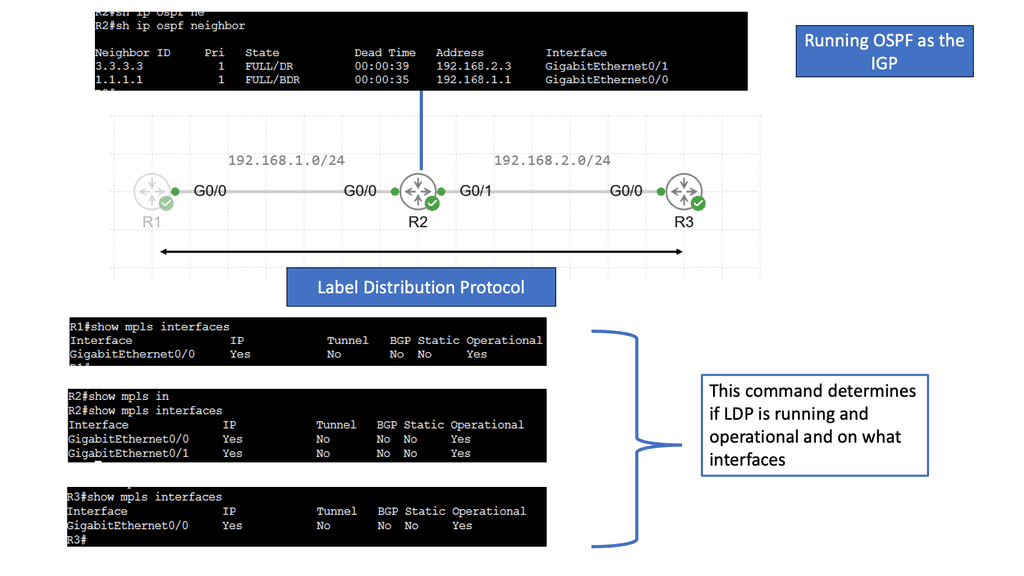
### The Role of LDP in MPLS Networks
The Label Distribution Protocol (LDP) is integral to the operation of MPLS networks, as it manages the distribution of labels between routers. LDP establishes label-switched paths (LSPs), which are the routes that data packets follow through an MPLS network. By automating the process of label distribution, LDP ensures efficient and consistent communication between routers, thus enhancing network reliability and performance. Understanding LDP is crucial for network engineers looking to implement or manage MPLS systems.
### Advantages of Using MPLS and LDP
The combination of MPLS and LDP offers numerous advantages. Firstly, MPLS can handle multiple types of traffic, such as IP packets, ATM, and Ethernet frames, making it versatile and adaptable. The use of labels instead of IP addresses results in faster data forwarding, reducing latency and improving network speed. Additionally, MPLS supports Quality of Service (QoS), allowing for prioritization of critical data, which is essential for applications like VoIP and video conferencing. LDP enhances these benefits by providing a robust framework for label management, ensuring network stability and efficiency.
Segment Routing – A Forwarding Paradigm
Segment routing is a forwarding paradigm that allows network operators to define packet paths by specifying a series of segments. These segments represent instructions that guide the packet’s journey through the network. Network engineers can optimize traffic flow, improve network scalability, and provide advanced services by leveraging segment routing.
**The Mechanics of Segment Routing**
At its core, Segment Routing leverages the source-routing principle. Instead of relying on each router to make forwarding decisions, SR allows the source node to encode the path a packet should take through the network. This path is defined by an ordered list of segments, which can be topological or service-based. By eliminating the need for complex signaling protocols, SR reduces overhead and simplifies the network infrastructure.
Recap: Segment routing leverages the concept of source routing, where the sender of a packet determines the complete path it will take through the network. Routers can effortlessly steer packets along a predefined path by assigning a unique identifier called a segment to each network hop, avoiding complex routing protocols and reducing network overhead.
Key Concepts – Components
To fully grasp segment routing, it’s essential to familiarize yourself with its key concepts and components. One fundamental element is the Segment Identifier (SID), which represents a specific network node or function. SIDs are used to construct explicit paths and enable traffic engineering. Another essential concept is the label stack, which allows routers to stack multiple SIDs together to form a forwarding path. Understanding these concepts is crucial for effectively implementing segment routing in network architectures.
**The Building Blocks**
- Segment IDs: Segment IDs are fundamental elements in segment routing. They uniquely identify a specific segment within the network. Depending on the network infrastructure, these IDs can be represented by various formats, such as IPv6 addresses or MPLS labels.
- Segment Routing Headers: Segment routing headers contain the segment instructions for packets. They are added to the packet’s header, indicating the sequence of segments to traverse. These headers provide the necessary information for routers to make forwarding decisions based on the defined segments.
**Traffic Engineering with Segment Routing**
- Traffic Steering: Segment routing enables precise traffic steering capabilities, allowing network operators to direct packets along specific paths based on their requirements. This fine-grained control enhances network efficiency and enables better utilization of network resources.
- Fast Reroute: Fast Reroute (FRR) is a crucial feature of segment routing that enhances network resiliency. By leveraging backup paths and pre-calculated segments, segment routing enables rapid traffic rerouting in case of link failures or congestion. This ensures minimal disruption and improved quality of service for critical applications.
**Integration with Network Services**
- Service Chaining: Segment routing seamlessly integrates with network services, enabling efficient service chaining. Service chaining directs traffic through a series of service functions, such as firewalls or load balancers, in a predefined order. With segment routing, this process becomes more streamlined and flexible.
- Network slicing: Network slicing leverages the capabilities of segment routing to create virtualized networks within a shared physical infrastructure. It enables the provisioning of isolated network slices tailored to specific requirements, guaranteeing performance, security, and resource isolation for different applications or tenants.
Understanding MPLS
MPLS, a versatile protocol, has been a stalwart in the networking industry for decades. It enables efficient packet forwarding by leveraging labels attached to packets for routing decisions. MPLS provides benefits such as traffic engineering, Quality of Service (QoS) control, and Virtual Private Network (VPN) support. Understanding the fundamental concepts of label switching and label distribution protocols is critical to grasping MPLS.
The Rise of Segment Routing
Segment Routing, on the other hand, is a relatively newer paradigm that simplifies network architectures and enhances flexibility. It leverages the concept of source routing, where the source node explicitly defines the path that packets should traverse through the network. By incorporating this approach, segment routing eliminates the need to maintain per-flow state information in network nodes, leading to scalability improvements and more accessible network management.
Key Differences and Synergies
While MPLS and Segment Routing have unique characteristics, they can also complement each other in various scenarios. Understanding the differences and synergies between these technologies is crucial for network architects and operators. MPLS offers a wide range of capabilities, including Traffic Engineering (MPLS-TE) and VPN services, while Segment Routing simplifies network operations and offers inherent traffic engineering capabilities.
MPLS and BGP-free Core
So, what is segment routing? Before discussing a segment routing solution and the details of segment routing vs. MPLS, let us recap how MPLS works and the protocols used. MPLS environments have both control and data plane elements.
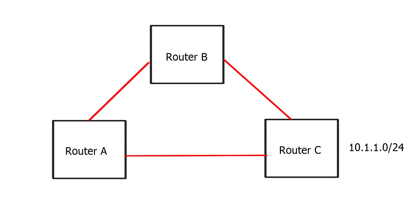
A BGP-free core operates at network edges, participating in full mesh or route reflection design. BGP is used to pass customer routes, Interior Gateway Protocol (IGP) to pass loopbacks, and Label Distribution Protocol (LDP) to label the loopback.
Example BGP Technology: BGP Route Reflection
**The Challenge of Scalability in BGP**
In large networks, maintaining a full mesh of BGP peering relationships becomes impractical. As the number of routers increases, the number of required connections grows exponentially. This complexity can lead to increased configuration errors, higher resource consumption, and slower convergence times, making network management a daunting task.
**Enter BGP Route Reflection**
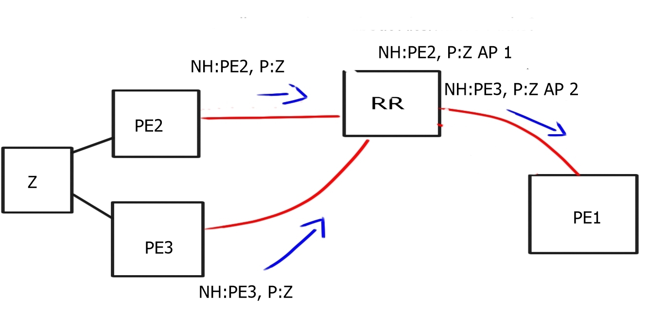
BGP Route Reflection is a clever solution to the scalability challenges of traditional BGP. By designating certain routers as route reflectors, network administrators can significantly reduce the number of BGP sessions required. These reflectors act as intermediaries, receiving routes from clients and redistributing them to other clients without the need for a full mesh.
**Benefits of BGP Route Reflection**
Implementing BGP Route Reflection offers numerous advantages. It simplifies network topology, reduces configuration complexity, and lowers the resource demands on routers. Additionally, it enhances network stability by minimizing the risk of configuration errors and improving convergence times during network changes or failures.


Labels and BGP next hops
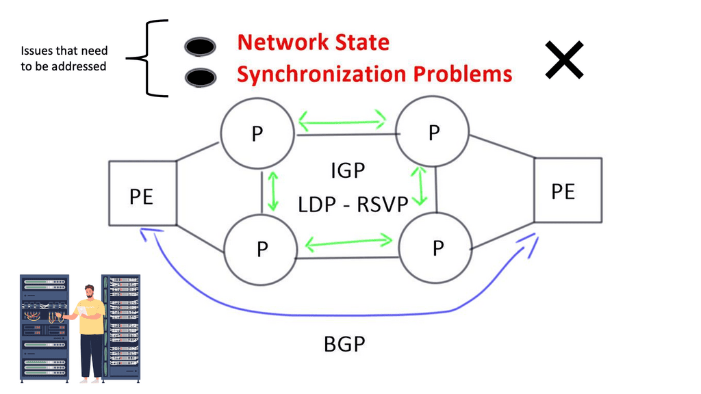
LDP or RSVP establishes MPLS label-switched paths ( LSPs ) throughout the network domain. Labels are assigned to the BGP next hops on every router where the IGP in the core provides reachability for remote PE BGP next hops.
As you can see, several control plane elements interact to provide complete end-to-end reachability. Unfortunately, the control plane is performed hop-by-hop, creating a network state and the potential for synchronization problems between LDP and IGP.
Related: Before you proceed, you may find the following post helpful:
Keep Complexity to Edges
In 2002, the IETF published RFC 3439, an Internet Architectural Guideline and Philosophy. It states, “In short, the complexity of the Internet belongs at the edges, and the IP layer of the Internet should remain as simple as possible.” When applying this concept to traditional MPLS-based networks, we must bring additional network intelligence and enhanced decision-making to network edges. Segment Routing is a way to get intelligence to the edge and Software-Defined Networking (SDN) concepts to MPLS-based architectures.
MPLS-based architectures:
MPLS, or Multiprotocol Label Switching, is a versatile networking technology that enables the efficient forwarding of data packets. Unlike traditional IP routing, MPLS utilizes labels to direct traffic along predetermined paths, known as Label Switched Paths (LSPs). This label-based approach offers enhanced speed, flexibility, and traffic engineering capabilities, making it a popular choice for modern network infrastructures.
Components of MPLS-Based Architectures
It is crucial to understand the workings of MPLS-based architectures’ key components. These include:
1. Label Edge Routers (LERs): LERs assign labels to incoming packets and forward them into the MPLS network.
2. Label Switch Routers (LSRs): LSRs form the core of the MPLS network, efficiently switching labeled packets along the predetermined LSPs.
3. Label Distribution Protocol (LDP): LDP facilitates the exchange of label information between routers, ensuring the proper establishment of LSPs.
Guide on a BGP-free core.
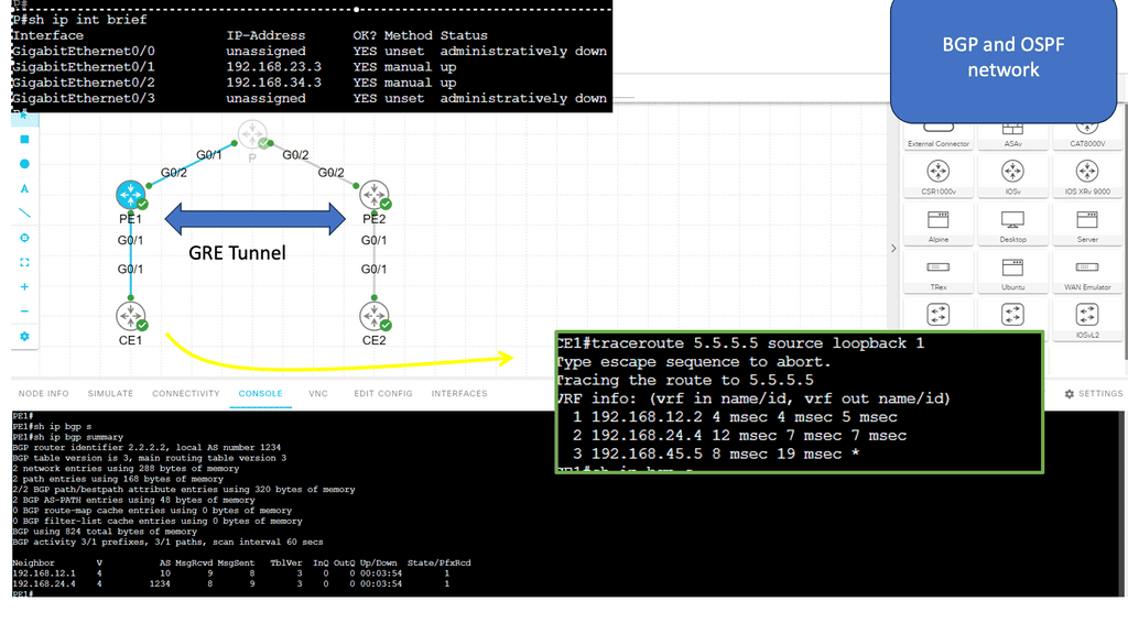
Here, we have a typically pre-MPLS setup. The main point is that the P node is only running OSPF. It does not know the CE routers or any other BGP routes. Then, BGP runs across a GRE tunnel to the CE nodes. The GRE tunnel we are running is point-to-point.
When we run a traceroute from CE1 to CE2, the packets traverse the GRE tunnel, and no P node interfaces are in the trace. The main goal here is to free up resources in the core, which is the starting point of MPLS networking. In the lab guide below, we will upgrade this to MPLS.
Source Packet Routing
Segment routing is a development of the Source Packet Routing in the Network (SPRING) working group of the IETF. The fundamental idea is the same as Service Function Chaining (SFC). Still, rather than assuming the processes along the path will manage the service chain, Segment Routing considers the routing control plane to handle the flow path through a network.
Segment routing (SR) is a source-based routing technique that streamlines traffic engineering across network domains. It removes network state information from transit routers and nodes and puts the path state information into packet headers at an ingress node.
MPLS Traffic Engineering
MPLS TE is an extension of MPLS, a protocol for efficiently routing data packets across networks. It provides a mechanism for network operators to control and manipulate traffic flow, allowing them to allocate network resources effectively. MPLS TE utilizes traffic engineering to optimize network paths and allocate bandwidth based on specific requirements.
It allows network operators to set up explicit paths for traffic, ensuring that critical applications receive the necessary resources and are not affected by congestion or network failures. MPLS TE achieves this by establishing Label Switched Paths (LSPs) that bypass potential bottlenecks and follow pre-determined routes, resulting in a more efficient and predictable network.
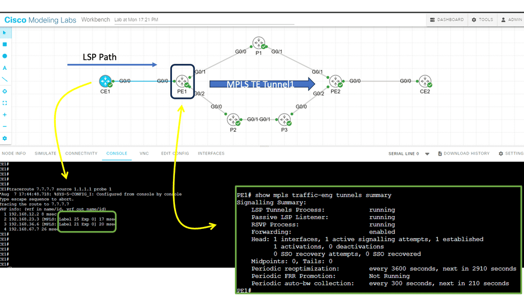
Guide on MPLS TE
In this lab, we will examine MPLS TE with ISIS configuration. Our MPLS core network comprises PE1, P1, P2, P3, and PE2 routers. The CE1 and CE2 routers use regular IP routing. All routers are configured to use IS-IS L2.
There are four main items we have to configure:
- Enable MPLS TE support:
- Globally
- Interfaces
- Configure IS-IS to support MPLS TE.
- Configure RSVP.
- Configure a tunnel interface.
**Synchronization Problems**
Packet loss can occur in two scenarios when the actions of IGP and LDP are not synchronized. Firstly, when an IGP adjacency is established, the router begins to forward packets using the new adjacency before the actual LDP exchange occurs between peers on that link.
Secondly, when an LDP session terminates, the router forwards traffic using the existing LDP peer link. This issue is resolved by implementing network kludges and turning on auto-synchronization between IGP and LDP. Additional configurations are needed to get these two control planes operating safely.
Solution – Segment Routing
Segment Routing is a new architecture built with SDN in mind. Separating data from the control plane is all about network simplification. SDN is a great concept; we must integrate it into today’s networks. The SDN concept of simplification is a driver for introducing Segment Routing.
Segment routing vs MPLS
Segment routing utilizes the basics of MPLS but with fewer protocols, less protocol interaction, and less state. It is also applied to MPLS architecture with no change to the forwarding plane. Existing devices switching based on labels may only need a software upgrade. The virtual overlay network concept is based on source routing. The source chooses the path you take through the network. It steers a packet through an ordered list of instructions called segments.
Like MPLS, Segment Routing is based on label switching without LDP or RSVP. Labels are called segments, and we still have push, swap, and pop actions. You do not keep the state in the middle of the network, as the state is in the packet instead. In the packet header, you put a list of segments. A segment is an instruction – if you want to go to C, use A-B-C.
- With Segment Routing, the Per-flow state is only maintained at the ingress node to the domain.
It is all about getting a flow concept, mapping it to a segment, and putting that segment on a true path. It keeps the properties of resilience ( fast reroute) but simplifies the approach with fewer protocols. As a result, it provides enhanced packet forwarding behavior while minimizing the need to maintain the network state.
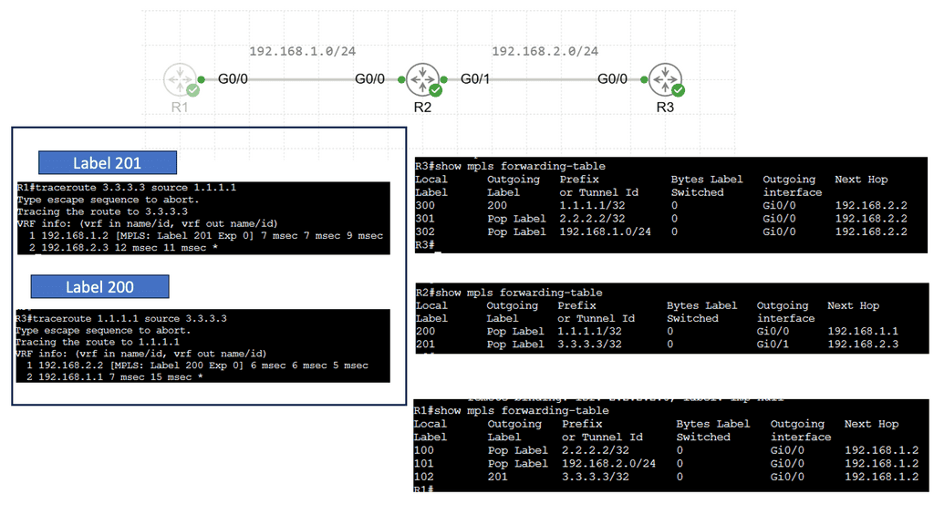
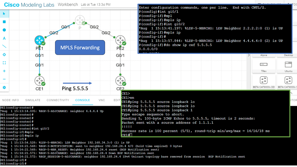
Guide on MPLS forwarding.
The previous lab guide can easily be upgraded to MPLS. We removed the GRE tunnel and the iBGP neighbors. MPLS is enabled with the mpls ip command on all interfaces on the P node and the PE node interfaces facing the P node. Now, we have MPLS forwarding based on labels while maintaining a BGP-free core. Notice how the two CEs can ping each other, and there is no route for 5.5.5.5 in the P node.
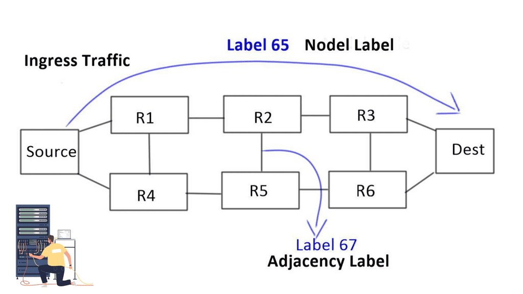
Two types of initial segments are defined
Node and Adjacency
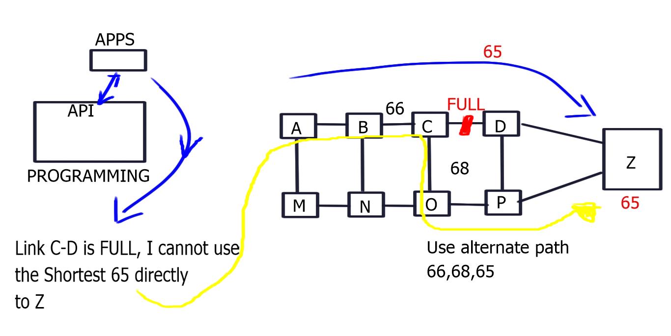
1- Nodel label: Nodel label is globally unique to each node. For example, a node labeled “Dest” has label 65 assigned to it, so any ingress network traffic with label 65 goes straight to Dest. By default, it will take the best path.
2- Then we have the Adjacency label: a locally significant label that takes packets to an adjacent path. It forces packets through a specific link and offers more specific path forwarding than a nodel label.
Segment routing: A new business model
Segment Routing addresses current issues and brings a new business model. It aims to address the pain points of existing MPLS/IP networks in terms of simplicity, scale, and ease of operation. Preparing the network with an SDN approach allows application integration directly on top of it.
Segment Routing allows you to take certain traffic types and make a routing decision based on that traffic class. It permits you to bring traffic that you think is important, such as Video or Voice, to go a different way than best efforts traffic.
Traffic paths can be programmed end-to-end for a specific class of customer. It moves away from the best-path model by looking at the network and deciding on the source. It is very similar to MPLS, but you use the labels differently.
SDN controller & network intelligence
Controller-based networks sit perfectly with this technology. It’s a very centralized and controller application methodology. The SDN controller gathers network telemetry information, decides based on a predefined policy, and pushes information to nodes to implement data path forwarding. Network intelligence such as link utilization, path response time, packet drops, latency, and jitter are extracted from the network and analyzed by the controller.
The intelligence now sits at the edges. The packet takes a path based on the network telemetry information extracted by the controller. The result is that the ingress node can push a label stack to the destination to take a specific path.
Your chosen path at the network’s edge is based on telemetry information.
Recap: Applications of Segment Routing:
1. Traffic Engineering and Load Balancing: Segment routing enables network operators to dynamically steer traffic along specific paths to optimize network resource utilization. This capability is handy in scenarios where certain links or nodes experience congestion, enabling network operators to balance the load and efficiently utilize available resources.
2. Service Chaining: Segment routing allows for the seamless insertion of network services, such as firewalls, load balancers, or WAN optimization appliances, into the packet’s path. By specifying the desired service segments, network operators can ensure traffic flows through the necessary services while maintaining optimal performance and security.
3. Network Slicing: With the advent of 5G and the proliferation of the Internet of Things (IoT) devices, segment routing can enable efficient network slicing. Network slicing allows for virtualized networks, each tailored to the specific requirements of different applications or user groups. Segment routing provides the flexibility to define and manage these virtualized networks, ensuring efficient resource allocation and isolation.
Segment Routing: Closing Points
Segment routing offers a promising solution to the challenges faced by modern network operators. Segment routing enables efficient and optimized utilization of network resources by providing simplified network operations, enhanced scalability, and traffic engineering flexibility.
With its applications ranging from traffic engineering to service chaining and network slicing, segment routing is poised to play a crucial role in the evolution of modern networks. As the demand for more flexible and efficient networks grows, segment routing emerges as a powerful tool for network operators to meet these demands and deliver a seamless and reliable user experience.