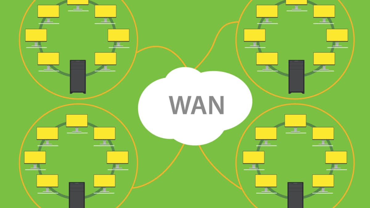
WAN Design Requirements

WAN SDN

WAN SDN

In today's fast-paced digital world, organizations constantly seek ways to optimize their network infrastructure for improved performance, scalability, and cost efficiency. One emerging technology that has gained significant traction is WAN Software-Defined Networking (SDN). By decoupling the control and data planes, WAN SDN provides organizations unprecedented flexibility, agility, and control over their wide area networks (WANs). In this blog post, we will delve into the world of WAN SDN, exploring its key benefits, implementation considerations, and real-world use cases.

WAN SDN is a network architecture that allows organizations to manage and control their wide area networks using software centrally. Traditionally, WANs have been complex and time-consuming to configure, often requiring manual network provisioning and management intervention. However, with WAN SDN, network administrators can automate these tasks through a centralized controller, simplifying network operations and reducing human errors.

Enhanced Agility: WAN SDN empowers network administrators with the ability to quickly adapt to changing business needs. With programmable policies and dynamic control, organizations can easily adjust network configurations, prioritize traffic, and implement changes without the need for manual reconfiguration of individual devices.

Improved Scalability: Traditional wide area networks often face scalability challenges due to the complex nature of managing numerous remote sites. WAN SDN addresses this issue by providing centralized control, allowing for streamlined network expansion, and efficient resource allocation.

Optimal Resource Utilization: WAN SDN enables organizations to maximize their network resources by intelligently routing traffic and dynamically allocating bandwidth based on real-time demands. This ensures that critical applications receive the necessary resources while minimizing wastage.

Multi-site Enterprises: WAN SDN is particularly beneficial for organizations with multiple branch locations. It allows for simplified network management across geographically dispersed sites, enabling efficient resource allocation, centralized security policies, and rapid deployment of new services.

Cloud Connectivity: WAN SDN plays a crucial role in connecting enterprise networks with cloud service providers. It offers seamless integration, secure connections, and dynamic bandwidth allocation, ensuring optimal performance and reliability for cloud-based applications.

Service Providers: WAN SDN can revolutionize how service providers deliver network services to their customers. It enables the creation of virtual private networks (VPNs) on-demand, facilitates network slicing for different tenants, and provides granular control and visibility for service-level agreements (SLAs).

WAN SDN represents a paradigm shift in wide area network management. Its ability to centralize control, enhance agility, and optimize resource utilization make it a game-changer for modern networking infrastructures. As organizations continue to embrace digital transformation and demand more from their networks, WAN SDN will undoubtedly play a pivotal role in shaping the future of networking.

Highlights: WAN SDN

Discussing WAN SDN

1: – ) Traditional WANs have long been plagued by various limitations, such as complexity, lack of agility, and high operational costs. These legacy networks typically rely on manual configurations and proprietary hardware, making them inflexible and time-consuming. SDN brings a paradigm shift to WANs by decoupling the network control plane from the underlying infrastructure. With centralized control and programmability, SDN enables network administrators to manage and orchestrate their WANs through a single interface, simplifying network operations and promoting agility.

2: – ) At its core, WAN SDN separates the control plane from the data plane, allowing network administrators to manage network traffic dynamically and programmatically. This separation leads to more efficient network management, reducing the complexity associated with traditional network infrastructures. With WAN SDN, businesses can optimize traffic flow, enhance security, and reduce operational costs by leveraging centralized control and automation.

3: – ) One of the key advantages of SDN in WANs is its inherent flexibility and scalability. With SDN, network administrators can dynamically allocate bandwidth, reroute traffic, and prioritize applications based on real-time needs. This level of granular control allows organizations to optimize their network resources efficiently and adapt to changing demands.

4: – )  SDN brings enhanced security features to WANs through centralized policy enforcement and monitoring. By abstracting network control, SDN allows for consistent security policies across the entire network, minimizing vulnerabilities and ensuring better threat detection and mitigation. Additionally, SDN enables rapid network recovery and failover mechanisms, enhancing overall resilience.

**Key Benefits of WAN SDN**

1. **Scalability and Flexibility**: WAN SDN enables networks to adapt quickly to changing demands without the need for significant hardware investments. This flexibility is crucial for organizations looking to scale their operations efficiently.

2. **Improved Network Performance**: By optimizing traffic routing and prioritizing critical applications, WAN SDN ensures that networks operate at peak performance levels. This capability is particularly beneficial for businesses with high bandwidth demands.

3. **Enhanced Security**: WAN SDN allows for the implementation of robust security measures, including automated threat detection and response. This proactive approach to security helps protect sensitive data and maintain compliance with industry regulations.

Routing Protocols Provide Dynamic Paths in WAN SDN

In a WAN SDN environment, routing protocols no longer operate as isolated control‑plane components. Instead, they feed real‑time path information into a centralized SDN controller, which evaluates multiple candidate routes across the WAN fabric. OSPF, BGP, and static routes become dynamic inputs rather than fixed decisions, allowing the controller to treat them as competing options for optimal WAN forwarding. This transforms the WAN from a collection of independent routers into a coordinated, policy‑driven forwarding system.
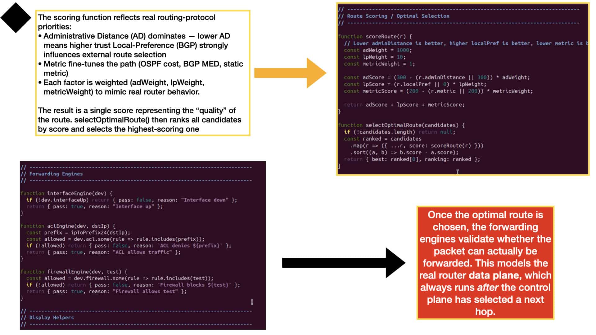
WAN SDN introduces a scoring and policy layer that ranks all available routes based on metrics such as administrative distance, bandwidth, latency, jitter, and business priority. The controller evaluates these factors to select the best end‑to‑end path across the WAN. Traditional routing metrics still matter, but SDN overlays add intent‑based logic that can prefer low‑latency paths for voice, high‑bandwidth paths for replication, or cost‑optimized paths for bulk traffic. The result is a WAN where the strongest path is chosen according to both routing intelligence and SDN policy.
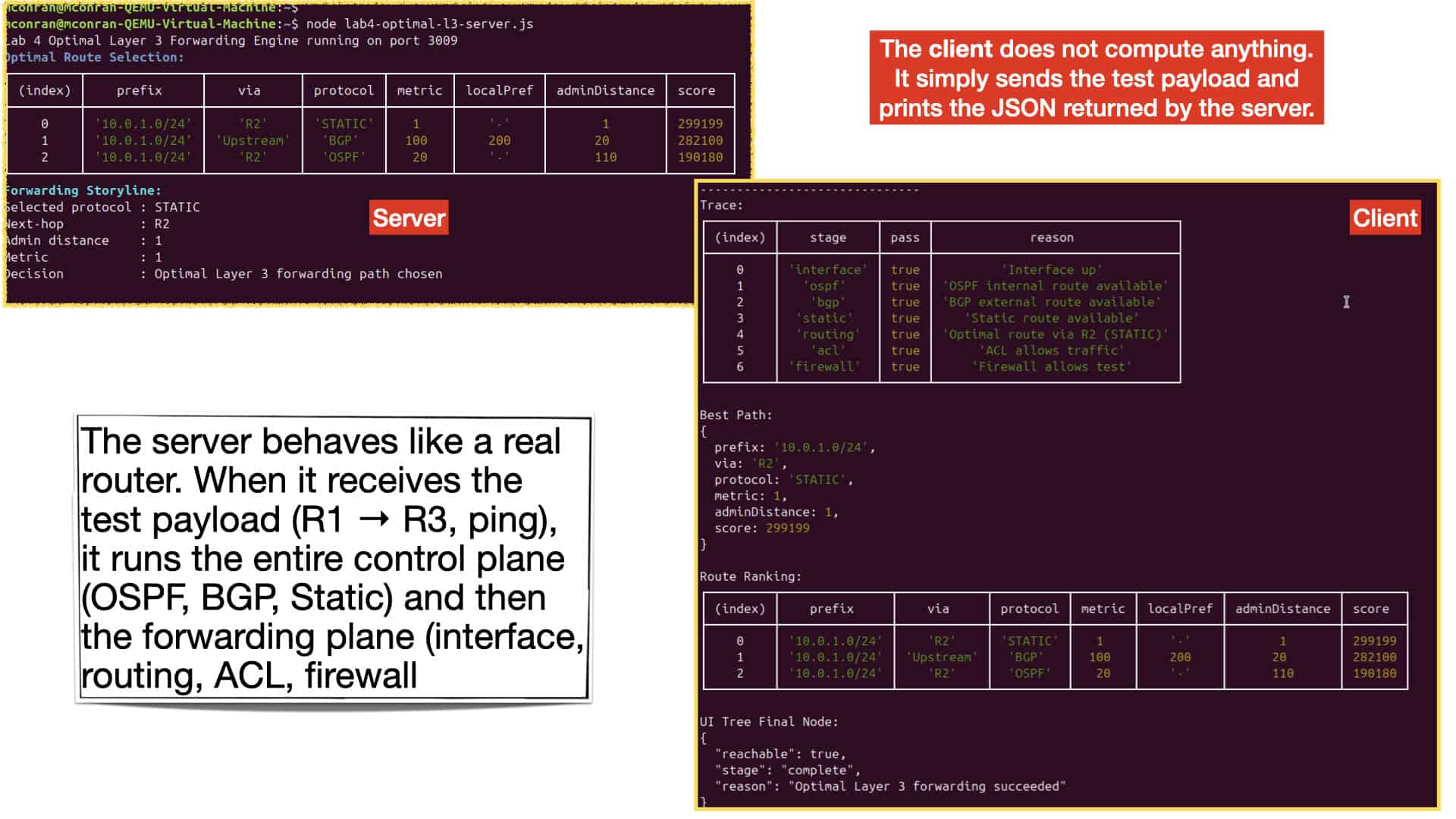
Once the SDN controller selects the optimal WAN path, the forwarding pipeline on each router enforces the decision. Interfaces must be operational, ACLs must allow the destination prefix, and security policies must permit the traffic type. Even in a fully automated WAN SDN architecture, the data plane remains authoritative: no SDN‑selected path is used unless the router’s forwarding checks pass. This ensures that WAN forwarding is not only optimal according to SDN logic, but also compliant with operational and security constraints across the entire WAN fabric.

Introducing WAN SDN Traffic Control

This lab demonstrates how WAN SDN traffic control can be implemented using a lightweight Node.js decision engine. Instead of relying on large enterprise controllers, the server evaluates simple telemetry such as application type, latency, trust score, posture, and identity headers. These inputs allow the WAN SDN engine to classify the session and apply steering rules that determine how the flow should be routed and secured. By keeping the logic minimal and transparent, learners can clearly see how modern WAN SDN systems make real‑time decisions based on application behaviour and security context.
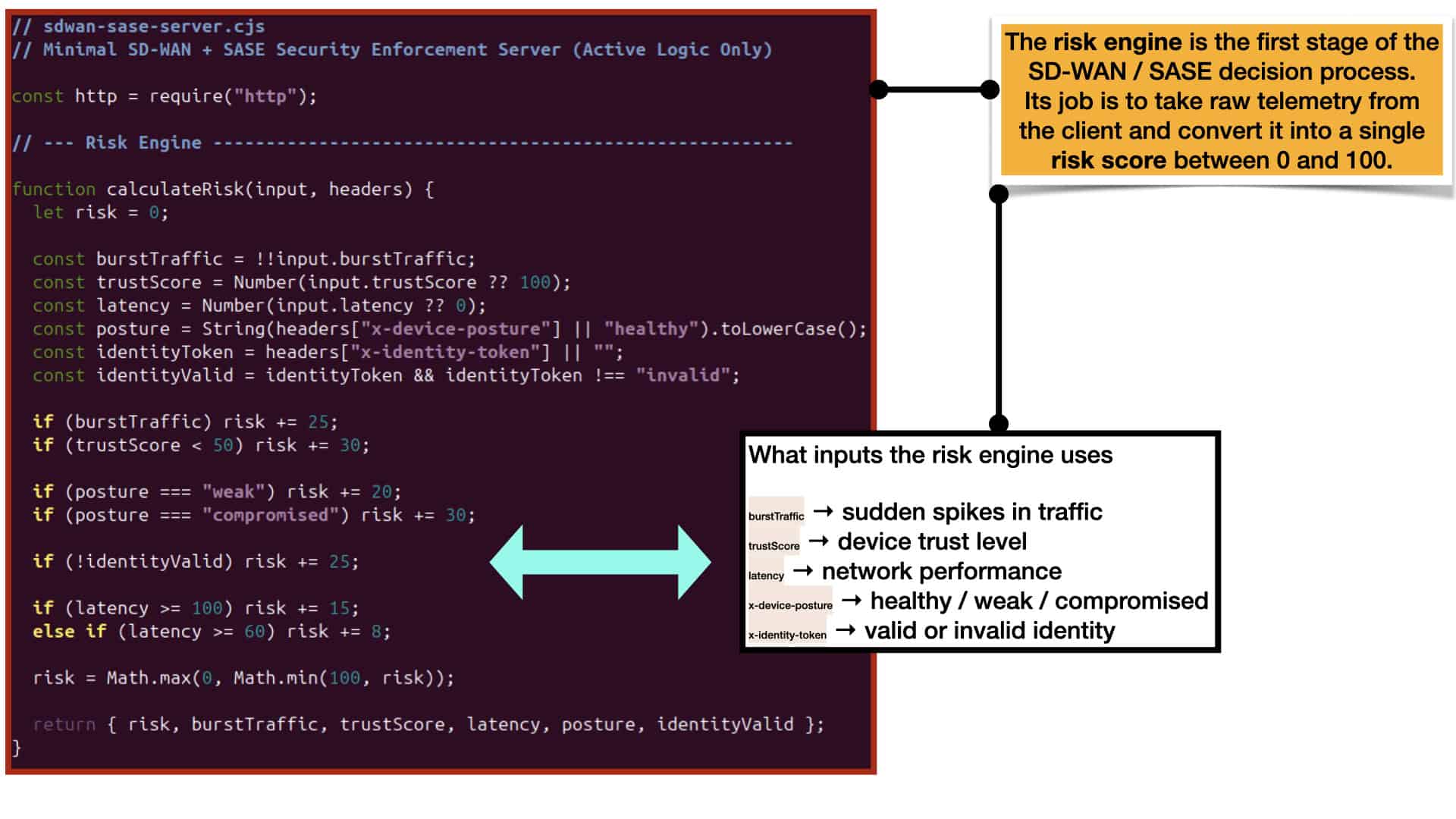
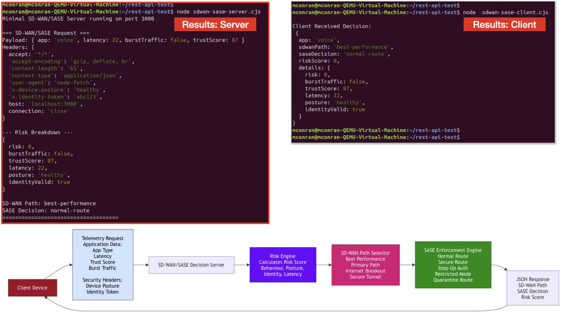
When the WAN SDN server starts, it listens for /steer requests and processes telemetry sent by the client. The client simulates a voice application with low latency and a healthy security posture, which is ideal for demonstrating WAN SDN steering in a clean, controlled environment. As soon as the request arrives, the server prints a full breakdown showing the risk evaluation, the selected path, and the security action. Because the session is trusted and stable, the WAN SDN logic selects the best‑performance path, while the security engine applies a normal‑route decision. This gives learners immediate visibility into how WAN SDN steering outcomes are generated.
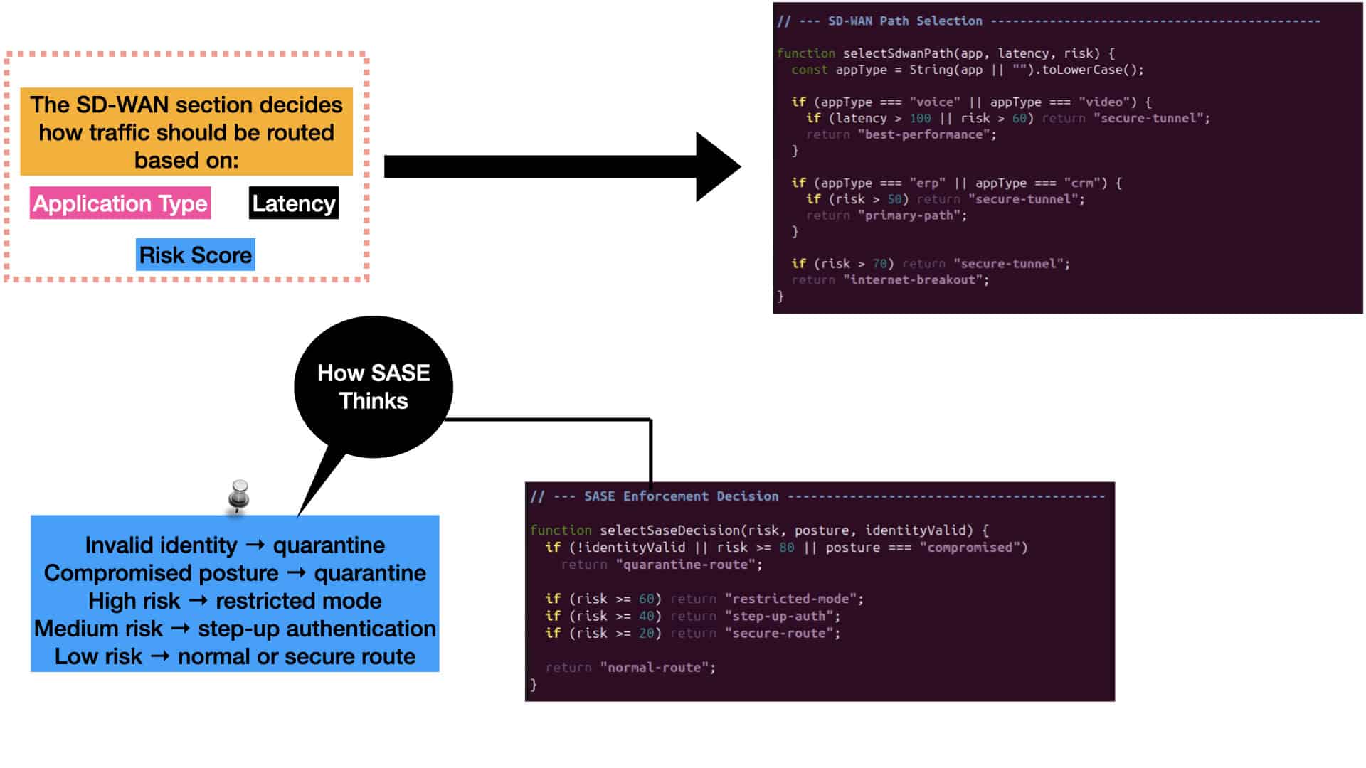
This lab highlights how WAN SDN combines performance requirements with security posture to produce adaptive routing outcomes. Even in its minimal form, the server shows how application type, latency, identity, and behavioural signals influence both the steering path and the enforcement action. The client’s JSON output mirrors the server’s internal logic, giving learners a clear view of how WAN SDN decisions are made end‑to‑end. With this foundation in place, additional labs can expand into Zero Trust, microsegmentation, identity enforcement, and more advanced behavioural steering models.
**Application Challenges**

Compared to a network-centric model, business intent-based WAN networks have great potential. By using a WAN architecture, applications can be deployed and managed more efficiently. However, application services topologies must replace network topologies. Supporting new and existing applications on the WAN is a common challenge for network operations staff. Applications such as these consume large amounts of bandwidth and are extremely sensitive to variations in bandwidth quality. Improving the WAN environment for these applications is more critical due to jitter, loss, and delay.

WAN SDN Identity‑Controlled Traffic Flows

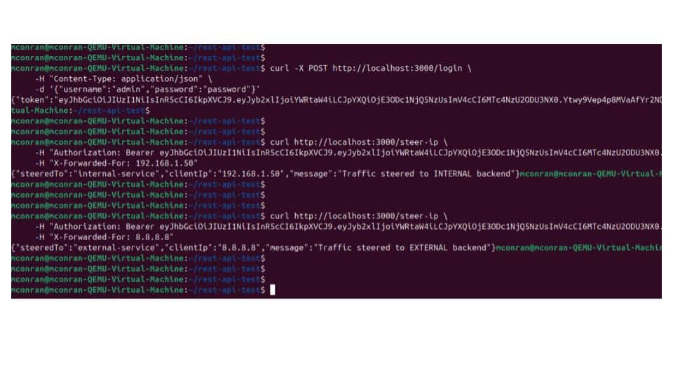
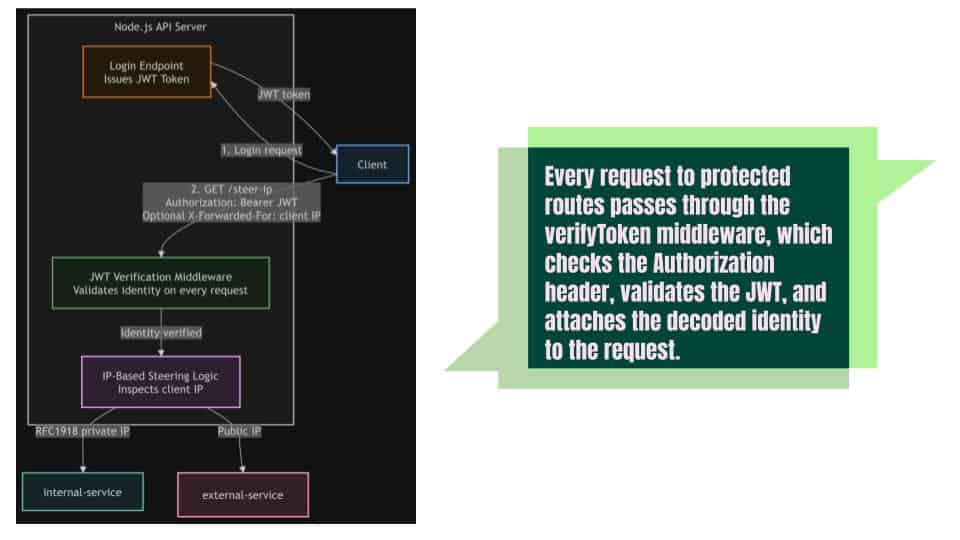
This server file demonstrates how WAN SDN principles can be applied at the application layer by enforcing identity before any traffic is allowed to move through the system. The login endpoint issues JWT tokens that act as identity credentials, similar to how a WAN SDN controller authenticates endpoints before installing forwarding rules across the WAN fabric. The JWT middleware validates each request, ensuring that only authenticated flows participate in the steering process. This mirrors WAN SDN’s foundational idea: centralized identity‑driven control over how traffic enters and moves across distributed networks.
IP header Steering

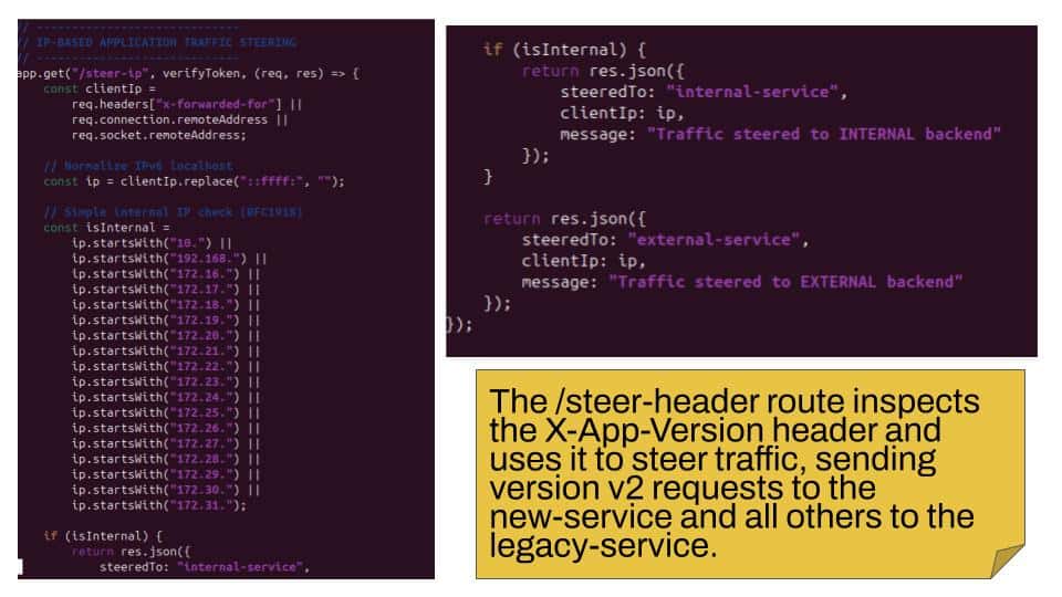
After identity is verified, the application applies WAN SDN‑style steering logic by inspecting the X-App-Version header to determine how traffic should be routed. In a WAN SDN environment, metadata such as application tags, service identifiers, or policy labels are used to classify flows and select the correct path across the WAN. The steering block in this file behaves the same way: it reads the version header and dynamically forwards the request to either the new‑service or the legacy‑service. This reflects how WAN SDN systems use contextual information to optimize routing decisions and enforce application‑aware forwarding.
IP header classification

The overall flow of this file showcases how WAN SDN concepts can be implemented through dynamic path selection at the application layer. Once a request passes identity validation and metadata inspection, the application determines the correct backend service to forward the flow to, effectively creating a simplified SDN‑style forwarding plane. Instead of relying on static routing or fixed service paths, the application makes real‑time decisions based on identity and context, just like a WAN SDN controller selecting optimal paths across a distributed WAN. This demonstrates how WAN SDN principles—centralized control, policy‑driven forwarding, and dynamic path selection—can be applied to shape and optimize application‑level connectivity.
IP steering

**WAN SLA**

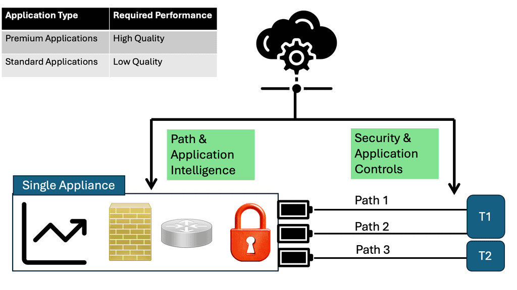
In addition, cloud-based applications such as Enterprise Resource Planning (ERP) and Customer Relationship Management (CRM) are increasing bandwidth demands on the WAN. As cloud applications require increasing bandwidth, provisioning new applications and services is becoming increasingly complex and expensive. In today’s business environment, WAN routing and network SLAs are controlled by MPLS L3VPN service providers. As a result, they are less able to adapt to new delivery methods, such as cloud-based and SaaS-based applications.

These applications could take months to implement in service providers’ environments. These changes can also be expensive for some service providers, and some may not be made at all. There is no way to instantiate VPNs independent of underlying transport since service providers control the WAN core. Implementing differentiated service levels for different applications becomes challenging, if not impossible.
WAN SDN Technology: DMVPN

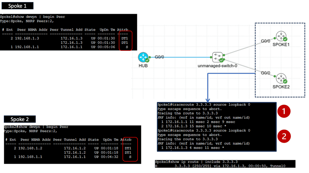
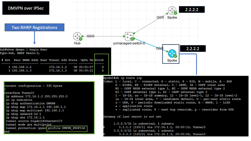
DMVPN is a Cisco-developed solution that enables the creation of virtual private networks over public or private networks. Unlike traditional VPNs that require point-to-point connections, DMVPN utilizes a hub-and-spoke architecture, allowing for dynamic and scalable network deployments. DMVPN simplifies network management and reduces administrative overhead by leveraging multipoint GRE tunnels.

– Multipoint GRE Tunnels: At the core of DMVPN lies the concept of multipoint GRE tunnels. These tunnels create a virtual network, connecting multiple sites while encapsulating packets in GRE headers. This enables efficient traffic routing between sites, reducing the complexity and overhead associated with traditional point-to-point VPNs.

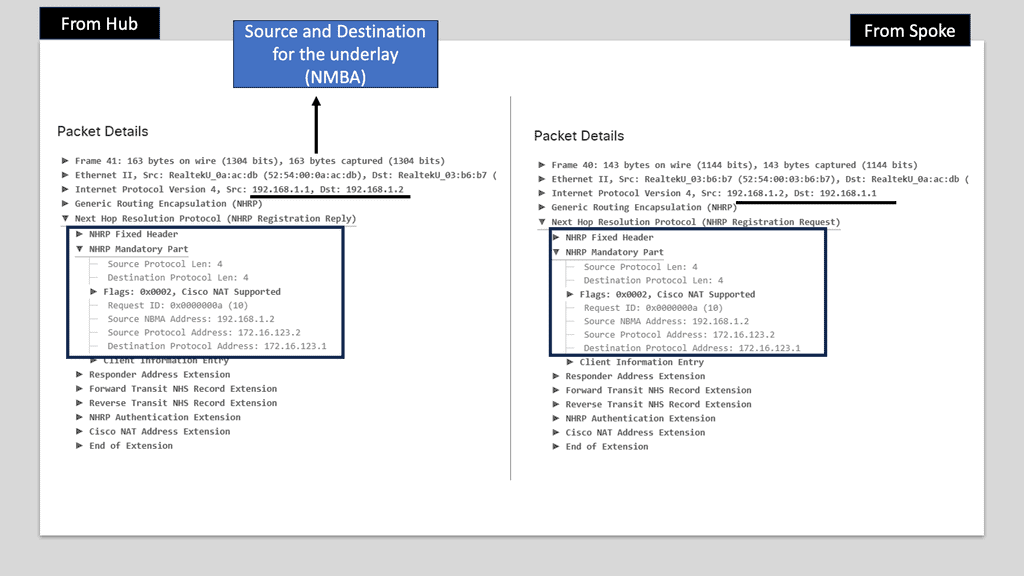
– Next-Hop Resolution Protocol (NHRP): NHRP plays a crucial role in DMVPN by dynamically mapping tunnel IP addresses to physical addresses. It allows for the efficient resolution of next-hop information, eliminating the need for static routes. NHRP also enables on-demand tunnel establishment, improving scalability and reducing administrative overhead.

– IPsec Encryption: DMVPN utilizes IPsec encryption to ensure secure communication over the VPN. IPsec provides confidentiality, integrity, and authentication of data, making it ideal for protecting sensitive information transmitted over the network. With DMVPN, IPsec is applied dynamically per-tunnelly, enhancing flexibility and scalability.

DMVPN over IPSec

Understanding DMVPN & IPSec

IPsec, a widely adopted security protocol, is integral to DMVPN deployments. It provides the cryptographic framework necessary for securing data transmitted over the network. By leveraging IPsec, DMVPN ensures the transmitted information’s confidentiality, integrity, and authenticity, protecting sensitive data from unauthorized access and tampering.

Firstly, the dynamic mesh topology eliminates the need for complex hub-and-spoke configurations, simplifying network management and reducing administrative overhead. Additionally, DMVPN’s scalability enables seamless integration of new sites and facilitates rapid expansion without compromising performance. Furthermore, the inherent flexibility ensures optimal routing, load balancing, and efficient bandwidth utilization.
Example WAN Techniques: 

Understanding Virtual Routing and Forwarding

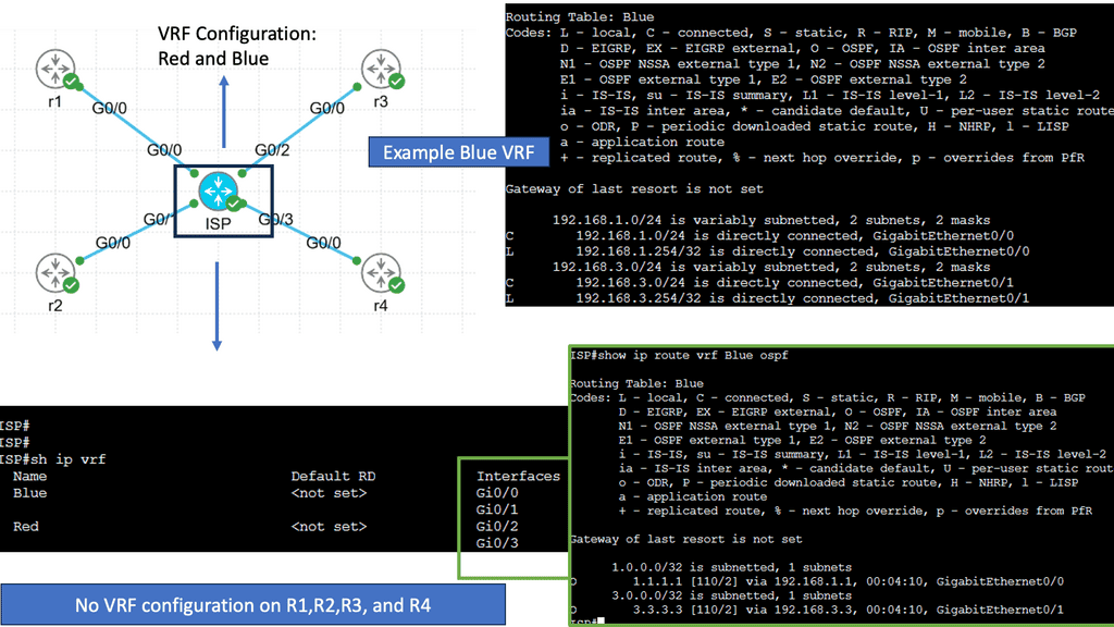
VRF is a technology that enables the creation of multiple virtual routing tables within a single physical router. Each VRF instance acts as an independent router with its routing table, interfaces, and forwarding decisions. This separation allows different networks or customers to coexist on the same physical infrastructure while maintaining complete isolation.

One critical advantage of VRF is its ability to provide network segmentation. By dividing a physical router into multiple VRF instances, organizations can isolate their networks, ensuring that traffic from one VRF does not leak into another. This enhances security and provides a robust framework for multi-tenancy scenarios.

Use Cases for VRF

VRF finds application in various scenarios, including:

1. Service Providers: VRF allows providers to offer their customers virtual private network (VPN) services. Each customer can have their own VRF, ensuring their traffic remains separate and secure.

2. Enterprise Networks: VRF can segregate different organizational departments, creating independent virtual networks.

3. Internet of Things (IoT): With the proliferation of IoT devices, VRF can create separate routing domains for different IoT deployments, improving scalability and security.
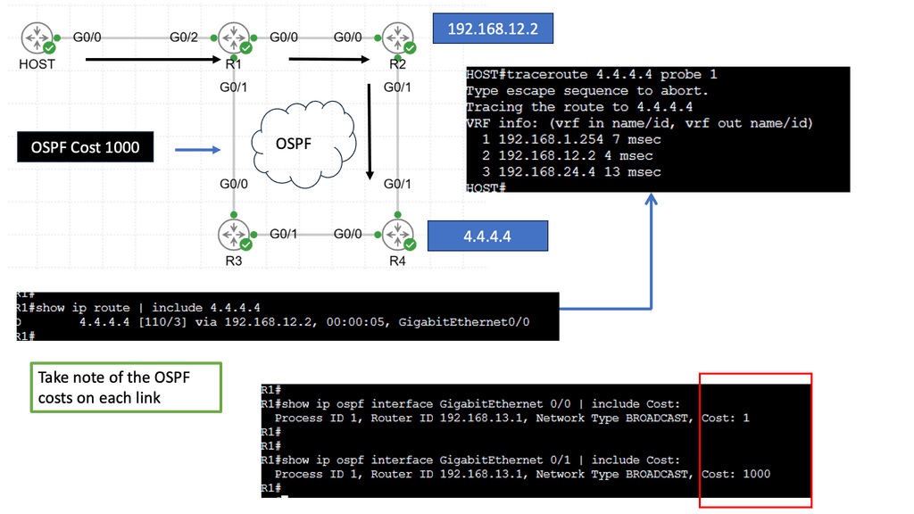
Understanding Policy-Based Routing

Policy-based Routing, at its core, involves manipulating routing decisions based on predefined policies. Unlike traditional routing protocols that rely solely on destination addresses, PBR considers additional factors such as source IP, ports, protocols, and even time of day. By implementing PBR, network administrators gain flexibility in directing traffic flows to specific paths based on specified conditions.

The adoption of Policy Based Routing brings forth a multitude of benefits. Firstly, it enables efficient utilization of network resources by allowing administrators to prioritize or allocate bandwidth for specific applications or user groups. Additionally, PBR enhances security by allowing traffic redirection to dedicated firewalls or intrusion detection systems. Furthermore, PBR facilitates load balancing and traffic engineering, ensuring optimal performance across the network.

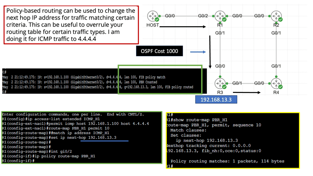
Implementing Policy-Based Routing

To implement PBR, network administrators must follow a series of steps. Firstly, the traffic classification criteria are defined by specifying the match criteria based on desired conditions. Secondly, create route maps that outline the actions for matched traffic. These actions may include altering the next-hop address, setting specific Quality of Service (QoS) parameters, or redirecting traffic to a different interface. Lastly, the route maps should be applied to the appropriate interfaces or specific traffic flows.
Example SD WAN Product: Cisco Meraki

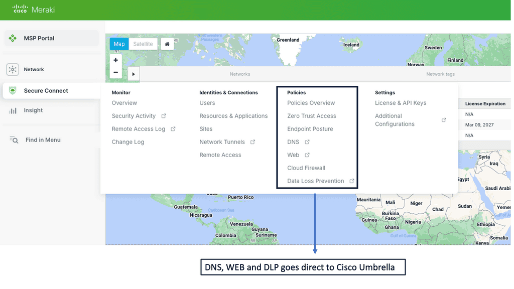
**Seamless Cloud Management**

One of the standout features of Cisco Meraki is its seamless cloud management. Unlike traditional network systems, Meraki’s cloud-based platform allows IT administrators to manage their entire network from a single, intuitive dashboard. This centralization not only simplifies network management but also provides real-time visibility and control over all connected devices. With automatic updates and zero-touch provisioning, businesses can ensure their network is always up-to-date and secure without the need for extensive manual intervention.
**Cutting-Edge Security Features**

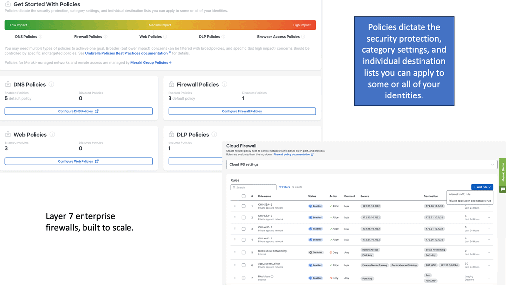
Security is at the core of Cisco Meraki’s suite of products. With cyber threats becoming more sophisticated, Meraki offers a multi-layered security approach to protect sensitive data. Features such as Advanced Malware Protection (AMP), Intrusion Prevention System (IPS), and secure VPNs ensure that the network is safeguarded against intrusions and malware. Additionally, Meraki’s security appliances are designed to detect and mitigate threats in real-time, providing businesses with peace of mind knowing their data is secure.

**Scalability and Flexibility**

As businesses grow, so do their networking needs. Cisco Meraki’s scalable solutions are designed to grow with your organization. Whether you are expanding your office space, adding new branches, or integrating more IoT devices, Meraki’s flexible infrastructure can easily adapt to these changes. The platform supports a wide range of devices, from access points and switches to security cameras and mobile device management, making it a comprehensive solution for various networking requirements.

**Enhanced User Experience**

Beyond security and management, Cisco Meraki enhances the user experience by ensuring reliable and high-performance network connectivity. Features such as intelligent traffic shaping, load balancing, and seamless roaming between access points ensure that users enjoy consistent and fast internet access. Furthermore, Meraki’s analytics tools provide insights into network usage and performance, allowing businesses to optimize their network for better efficiency and user satisfaction.
Performance at the WAN Edge

Understanding Performance-Based Routing

Performance-based routing is a dynamic approach to network traffic management that prioritizes route selection based on real-time performance metrics. Instead of relying on traditional static routing protocols, performance-based routing algorithms assess the current conditions of network paths, such as latency, packet loss, and available bandwidth, to make informed routing decisions. By dynamically adapting to changing network conditions, performance-based routing aims to optimize traffic flow and enhance overall network performance.

The adoption of performance-based routing brings forth a multitude of benefits for businesses.

1- Firstly, it enhances network reliability by automatically rerouting traffic away from congested or underperforming paths, minimizing the chances of bottlenecks and service disruptions.

2- Secondly, it optimizes application performance by intelligently selecting the best path based on real-time network conditions, thus reducing latency and improving end-user experience. A

3- Additionally, performance-based routing allows for efficient utilization of available network resources, maximizing bandwidth utilization and cost-effectiveness.

Implementation Details:

Implementing performance-based routing requires a thoughtful approach. Firstly, businesses must invest in monitoring tools that provide real-time insights into network performance metrics. These tools can range from simple latency monitoring to more advanced solutions that analyze packet loss and bandwidth availability.

Once the necessary monitoring infrastructure is in place, configuring performance-based routing algorithms within network devices becomes the next step. This involves setting up rules and policies that dictate how traffic should be routed based on specific performance metrics.

Lastly, regular monitoring and fine-tuning performance-based routing configurations are essential to ensure optimal network performance.
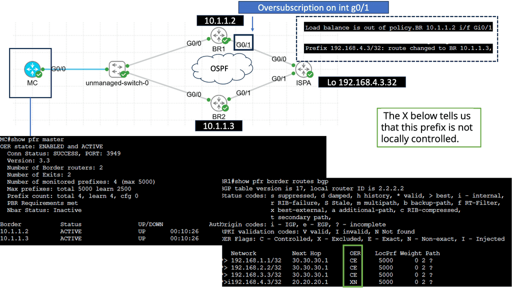
WAN Performance Parameters

TCP Performance Parameters

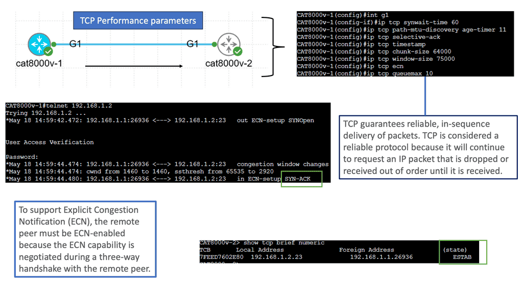
TCP (Transmission Control Protocol) is the backbone of modern Internet communication, ensuring reliable data transmission across networks. Behind the scenes, TCP performance is influenced by several key parameters that can significantly impact network efficiency.

TCP performance parameters govern how TCP behaves in various network conditions. These parameters can be fine-tuned to adapt TCP’s behavior to specific network characteristics, such as latency, bandwidth, and congestion. By adjusting these parameters, network administrators and system engineers can optimize TCP performance for better throughput, reduced latency, and improved overall network efficiency.

Congestion Control Algorithms: Congestion control algorithms are crucial in TCP performance. They monitor network conditions, detect congestion, and adjust TCP’s sending rate accordingly. Popular algorithms like Reno, Cubic, and BBR implement different strategies to handle congestion, balancing fairness and efficiency. Understanding these algorithms and their impact on TCP behavior is essential for maintaining a stable and responsive network.

Window Size and Bandwidth Delay Product: The window size parameter, often called the congestion window, determines the amount of data that can be sent before receiving an acknowledgment. The bandwidth-delay product should set the window size, a value calculated by multiplying the available bandwidth with the round-trip time (RTT). Adjusting the window size to match the bandwidth-delay product ensures optimal data transfer and prevents underutilization or overutilization of network resources.

Maximum Segment Size (MSS): The Maximum Segment Size is another TCP performance parameter defining the maximum amount of data encapsulated within a single TCP segment. By carefully configuring the MSS, it is possible to reduce packet fragmentation, enhance data transmission efficiency, and mitigate issues related to network overhead.

Selective Acknowledgment (SACK): Selective Acknowledgment is a TCP extension that allows the receiver to acknowledge out-of-order segments and provide more precise information about the received data. Enabling SACK can improve TCP performance by reducing retransmissions and enhancing the overall reliability of data transmission.
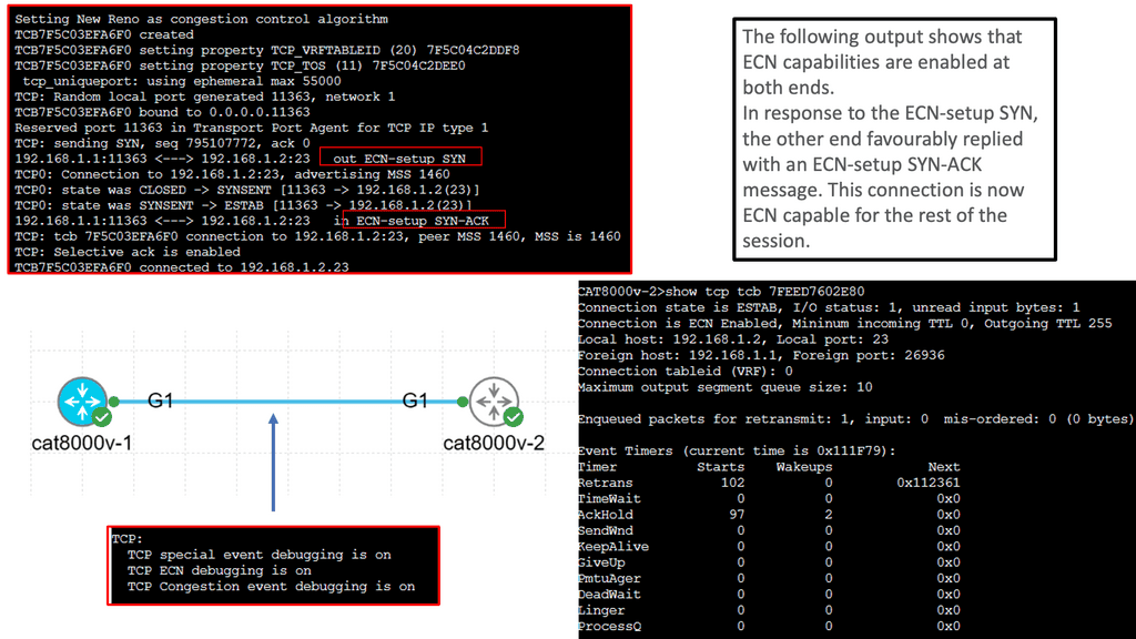
Understanding TCP MSS

TCP MSS refers to the maximum amount of data encapsulated within a single TCP segment. It represents the most significant data payload that can be transmitted without fragmentation. By limiting the segment size, TCP aims to prevent excessive overhead and ensure efficient data transmission across networks.

Several factors influence the determination of TCP MSS. One crucial aspect is the underlying network infrastructure’s Maximum Transmission Unit (MTU). The MTU represents the maximum packet size that can be transmitted over the network without fragmentation. TCP MSS must be set to a value equal to or lower than the MTU to avoid fragmentation and subsequent performance degradation.

Path MTU Discovery (PMTUD) is a mechanism TCP employs to dynamically determine the optimal MSS value for a given network path. By exchanging ICMP messages with routers along the path, TCP can ascertain the MTU and adjust the MSS accordingly. PMTUD helps prevent packet fragmentation and ensures efficient data transmission across network segments.

The TCP MSS value directly affects network performance. A smaller MSS can increase overhead due to more segments and headers, potentially reducing overall throughput. On the other hand, a larger MSS can increase the risk of fragmentation and subsequent retransmissions, impacting latency and overall network efficiency. Striking the right balance is crucial for optimal performance.

Example WAN Technology: DMVPN Phase 3

Understanding DMVPN Phase 3

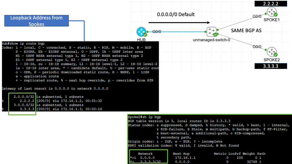
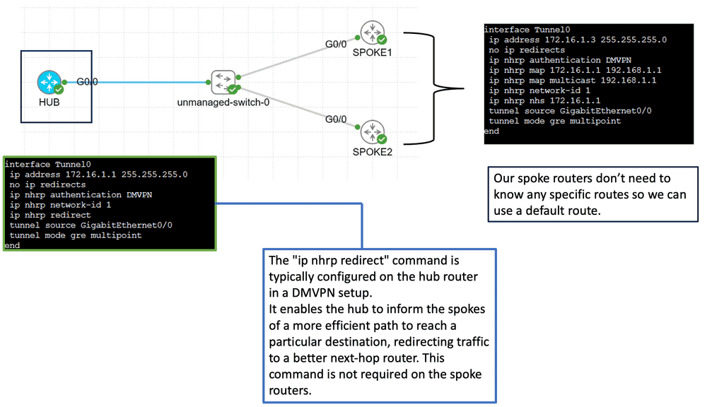
DMVPN Phase 3 builds upon the foundation of its predecessors, bringing forth even more advanced features. This section will provide an overview of DMVPN Phase 3, highlighting its main enhancements, such as increased scalability, simplified configuration, and enhanced security protocols.

One of the standout features of DMVPN Phase 3 is its scalability. This section will explain how DMVPN Phase 3 allows organizations to effortlessly add new sites to the network without complex manual configurations. By leveraging multipoint GRE tunnels, DMVPN Phase 3 offers a dynamic and flexible solution that can easily accommodate growing networks.
Example WAN Technology: FlexVPN Site-to-Site Smart Defaults

Understanding FlexVPN Site-to-Site Smart Defaults

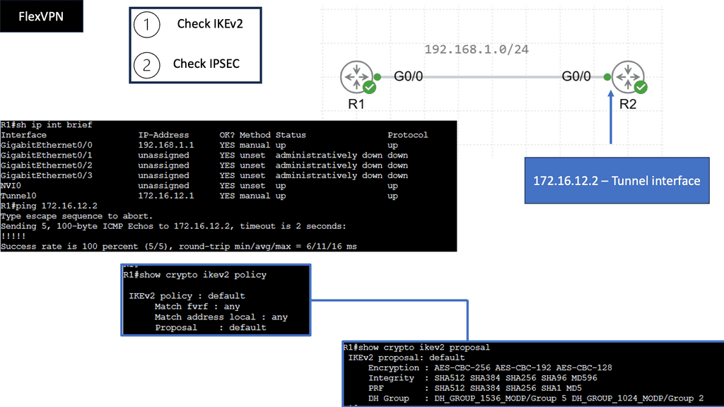
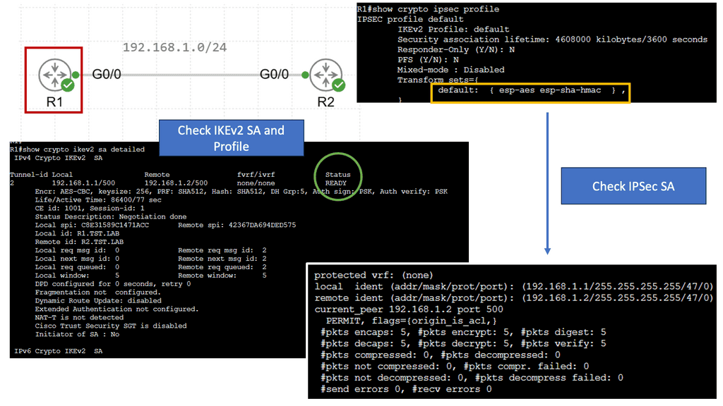
FlexVPN Site-to-Site Smart Defaults is a powerful feature that simplifies site-to-site VPN configuration and deployment process. Providing pre-defined templates and configurations eliminates the need for manual configuration, reducing the chances of misconfigurations or human errors. This feature ensures a secure and reliable VPN connection between sites, enabling organizations to establish a robust network infrastructure.

FlexVPN Site-to-Site Smart Defaults offers several key features and benefits that contribute to improved network security. Firstly, it provides secure cryptographic algorithms that protect data transmission, ensuring the confidentiality and integrity of sensitive information. Additionally, it supports various authentication methods, such as digital certificates and pre-shared keys, further enhancing the overall security of the VPN connection. The feature also allows for easy scalability, enabling organizations to expand their network infrastructure without compromising security.
Example WAN Technology: FlexVPN IKEv2 Routing

Understanding FlexVPN

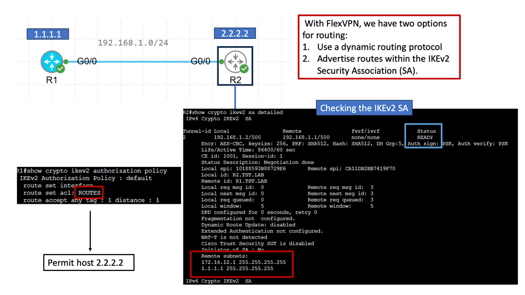
FlexVPN, short for Flexible VPN, is a versatile framework offering various VPN solutions. It provides a secure and scalable approach to establishing Virtual Private Networks (VPNs) over various network infrastructures. With its flexibility, it allows for seamless integration and interoperability across different platforms and devices.

IKEv2, or Internet Key Exchange version 2, is a secure and efficient protocol for establishing and managing VPN connections. It boasts numerous advantages, including its robust security features, ability to handle network disruptions, and support for rapid reconnection. IKEv2 is highly regarded for its ability to maintain stable and uninterrupted VPN connections, making it an ideal choice for FlexVPN.

a. Enhanced Security: FlexVPN IKEv2 Routing offers advanced encryption algorithms and authentication methods, ensuring the confidentiality and integrity of data transmitted over the VPN.

b. Scalability: With its flexible architecture, FlexVPN IKEv2 Routing effortlessly scales to accommodate growing network demands, making it suitable for small—to large-scale deployments.

c. Dynamic Routing: One of FlexVPN IKEv2 Routing’s standout features is its support for dynamic routing protocols, such as OSPF and EIGRP. This enables efficient and dynamic routing of traffic within the VPN network.

d. Seamless Failover: FlexVPN IKEv2 Routing provides automatic failover capabilities, ensuring uninterrupted connectivity even during network disruptions or hardware failures.
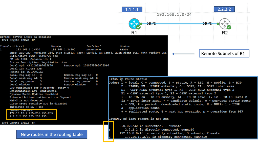
Understanding MPLS (Multi-Protocol Label Switching)

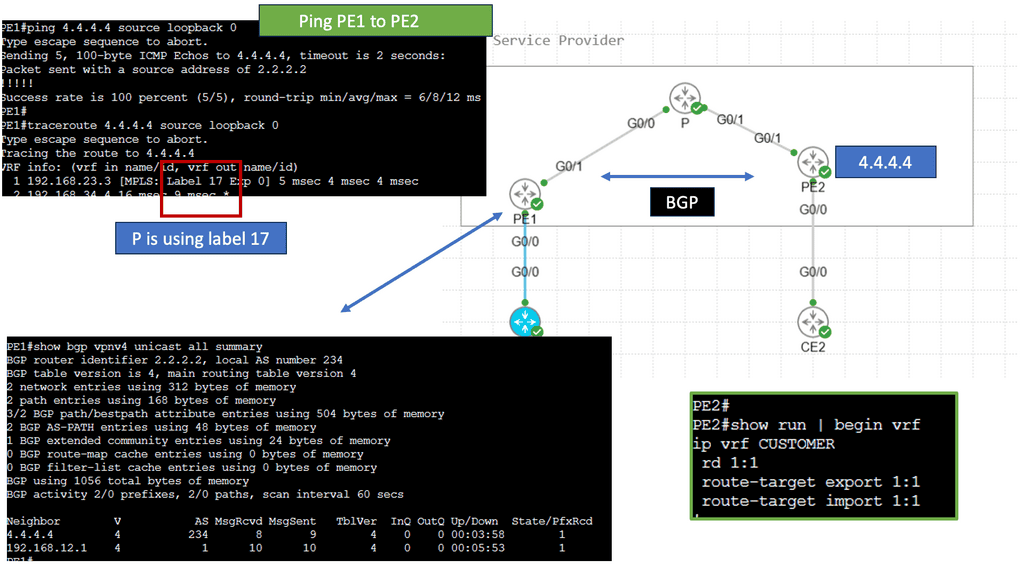
MPLS serves as the foundation for MPLS VPNs. It is a versatile and efficient routing technique that uses labels to forward data packets through a network. By assigning labels to packets, MPLS routers can make fast-forwarding decisions based on the labels, reducing the need for complex and time-consuming lookups in routing tables. This results in improved network performance and scalability.

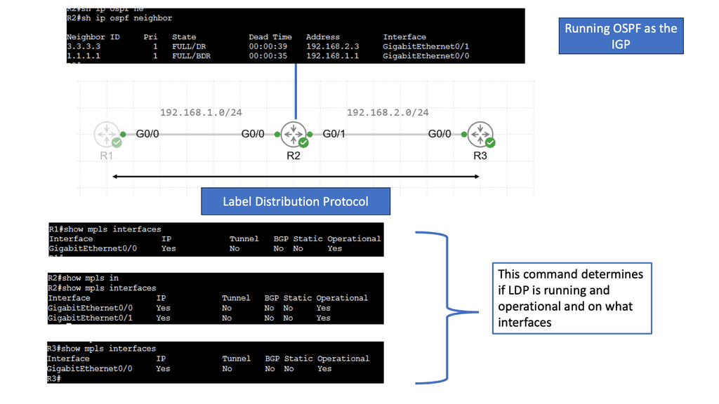
Understanding MPLS LDP

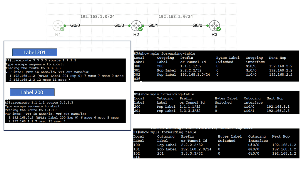
MPLS LDP is a crucial component in establishing label-switched paths within MPLS networks. MPLS LDP facilitates efficient packet forwarding and routing by enabling the distribution of labels and creating forwarding equivalency classes. Let’s take a closer look at how MPLS LDP operates.

One of the fundamental aspects of MPLS LDP is label distribution. Through signaling protocols, MPLS LDP ensures that labels are assigned and distributed across network nodes. This enables routers to make forwarding decisions based on labels, resulting in streamlined and efficient data transmission.

In MPLS LDP, labels serve as the building blocks of label-switched paths. These paths allow routers to forward packets based on labels rather than traditional IP routing. Additionally, MPLS LDP employs forwarding equivalency classes (FECs) to group packets with similar characteristics, further enhancing network performance.
MPLS Virtual Private Networks (VPNs) Explained

VPNs provide secure communication over public networks by creating a private tunnel through which data can travel. They employ encryption and tunneling protocols to protect data from eavesdropping and unauthorized access. MPLS VPNs utilize this VPN concept to establish secure connections between geographically dispersed sites or remote users.

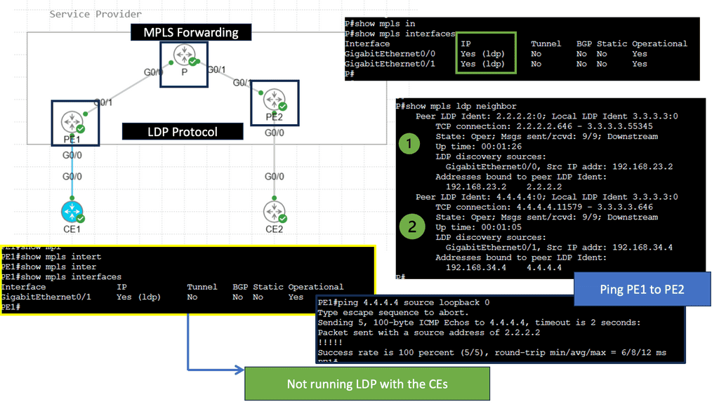
MPLS VPN Components

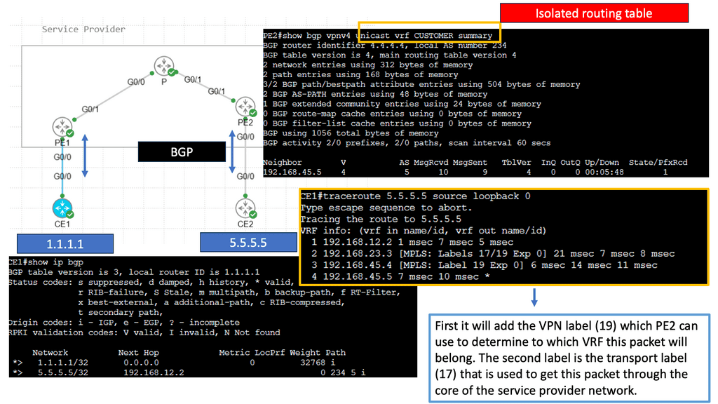
Customer Edge (CE) Router: The CE router acts as the entry and exit point for customer networks. It connects to the provider network and exchanges routing information. It encapsulates customer data into MPLS packets and forwards them to the provider network.

Provider Edge (PE) Router: The PE router sits at the edge of the service provider’s network and connects to the CE routers. It acts as a bridge between the customer and provider networks and handles the MPLS label switching. The PE router assigns labels to incoming packets and forwards them based on the labels’ instructions.

Provider (P) Router: P routers form the backbone of the service provider’s network. They forward MPLS packets based on the labels without inspecting the packet’s content, ensuring efficient data transmission within the provider’s network.

Virtual Routing and Forwarding (VRF) Tables: VRF tables maintain separate routing instances within a single PE router. Each VRF table represents a unique VPN and keeps the customer’s routing information isolated from other VPNs. VRF tables enable the PE router to handle multiple VPNs concurrently, providing secure and independent communication channels.
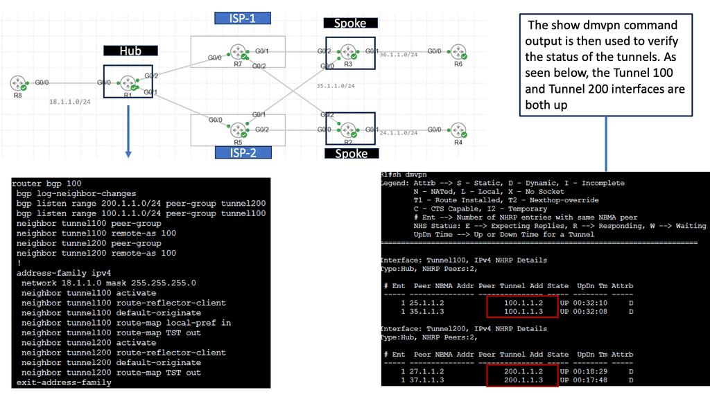
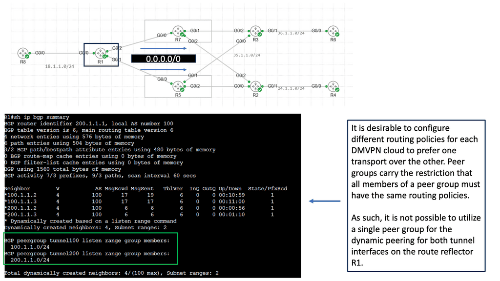
Use Case – DMVPN Single Hub, Dual Cloud

Single Hub, Dual Cloud is a specific configuration within the DMVPN architecture. In this setup, a central hub device acts as the primary connection point for branch offices while utilizing two separate cloud providers for redundancy and load balancing. This configuration offers several advantages, including improved availability, increased bandwidth, and enhanced failover capabilities.

1. Enhanced Redundancy: By leveraging two cloud providers, organizations can achieve high availability and minimize downtime. If one cloud provider experiences an issue or outage, the traffic can seamlessly be redirected to the alternate provider, ensuring uninterrupted connectivity.

2. Load Balancing: Distributing network traffic across two cloud providers allows for better resource utilization and improved performance. Organizations can optimize their bandwidth usage and mitigate potential bottlenecks.

3. Scalability: Single Hub, Dual Cloud DMVPN allows organizations to easily scale their network infrastructure by adding more branch offices or cloud providers as needed. This flexibility ensures that the network can adapt to changing business requirements.

4. Cost Efficiency: Utilizing multiple cloud providers can lead to cost savings through competitive pricing and the ability to negotiate better service level agreements (SLAs). Organizations can choose the most cost-effective options while maintaining the desired level of performance and reliability.
The role of SDN

With software-defined networking (SDN), network configurations can be dynamic and programmatically optimized, improving network performance and monitoring more like cloud computing than traditional network management. By disassociating the forwarding of network packets from routing (control plane), SDN can be used to centralize network intelligence within a single network component by improving the static architecture of traditional networks.

Controllers make up the control plane of an SDN network, which contains all of the network’s intelligence. They are considered the brains of the network. Security, scalability, and elasticity are some of the drawbacks of centralization.

Since OpenFlow’s emergence in 2011, SDN was commonly associated with remote communication with network plane elements to determine the path of network packets across network switches. Additionally, proprietary network virtualization platforms, such as Cisco Systems’ Open Network Environment and Nicira’s, use the term.

The SD-WAN technology is used in wide area networks (WANs)

SD-WAN, short for Software-Defined Wide Area Networking, is a transformative approach to network connectivity. Unlike traditional WAN, which relies on hardware-based infrastructure, SD-WAN utilizes software and cloud-based technologies to connect networks over large geographic areas securely. By separating the control plane from the data plane, SD-WAN provides centralized management and enhanced flexibility, enabling businesses to optimize their network performance.

Transport Independance: Hybrid WAN

The hybrid WAN concept was born out of this need. An alternative path that applications can take across a WAN environment is provided by hybrid WAN, which involves businesses acquiring non-MPLS networks and adding them to their LANs. Business enterprises can control these circuits, including routing and application performance. VPN tunnels are typically created over the top of these circuits to provide secure transport over any link. 4G/LTE, L2VPN, commodity broadband Internet, and L2VPN are all examples of these types of links.

As a result, transport independence is achieved. In this way, any transport type can be used under the VPN, and deterministic routing and application performance can be achieved. These commodity links can transmit some applications rather than the traditionally controlled L3VPN MPLS links provided by service providers.

SDN and APIs

WAN SDN is a modern approach to network management that uses a centralized control model to manage, configure, and monitor large and complex networks. It allows network administrators to use software to configure, monitor, and manage network elements from a single, centralized system. This enables the network to be managed more efficiently and cost-effectively than traditional networks.

SDN uses an application programming interface (API) to abstract the underlying physical network infrastructure, allowing for more agile network control and easier management. It also enables network administrators to rapidly configure and deploy services from a centralized location. This enables network administrators to respond quickly to changes in traffic patterns or network conditions, allowing for more efficient use of resources.

Scalability and Automation

SDN also allows for improved scalability and automation. Network administrators can quickly scale up or down the network by leveraging automated scripts depending on its current needs. Automation also enables the network to be maintained more rapidly and efficiently, saving time and resources.

Before you proceed, you may find the following posts helpful:

  1. WAN Virtualization
  2. Software Defined Perimeter Solutions
  3. What is OpenFlow
  4. SD WAN Tutorial
  5. What Does SDN Mean
  6. Data Center Site Selection

WAN SDN

A Deterministic Solution

Technology typically starts as a highly engineered, expensive, deterministic solution. As the marketplace evolves and competition rises, the need for a non-deterministic, inexpensive solution comes into play. We see this throughout history. First, mainframes were/are expensive, and with the arrival of a microprocessor personal computer, the client/server model was born. The Static RAM ( SRAM ) technology was replaced with cheaper Dynamic RAM ( DRAM ). These patterns consistently apply to all areas of technology.

Finally, deterministic and costly technology is replaced with intelligent technology using redundancy and optimization techniques. This process is now appearing in Wide Area Networks (WAN). Now, we are witnessing changes to routing space with the incorporation of Software Defined Networking (SDN) and BGP (Border Gateway Protocol). By combining these two technologies, companies can now perform  intelligent routing, aka SD-WAN path selection, with an SD WAN Overlay

**SD-WAN Path Selection**

SD-WAN path selection is essential to a Software-Defined Wide Area Network (SD-WAN) architecture. SD-WAN path selection selects the most optimal network path for a given application or user. This process is automated and based on user-defined criteria, such as latency, jitter, cost, availability, and security. As a result, SD-WAN can ensure that applications and users experience the best possible performance by making intelligent decisions on which network path to use.

When selecting the best path for a given application or user, SD-WAN looks at the quality of the connection and the available bandwidth. It then looks at the cost associated with each path. Cost can be a significant factor when selecting a path, especially for large enterprises or organizations with multiple sites.

SD-WAN can also prioritize certain types of traffic over others. This is done by assigning different weights or priorities for various kinds of traffic. For example, an organization may prioritize voice traffic over other types of traffic. This ensures that voice traffic has the best possible chance of completing its journey without interruption.
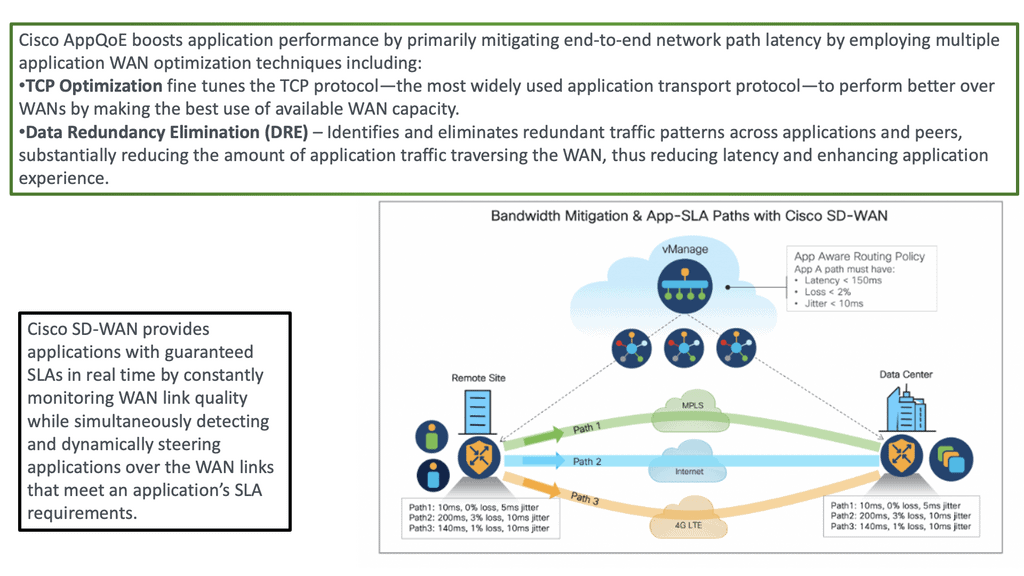
SD WAN traffic steering
Diagram: SD WAN traffic steering. Source Cisco.

Critical Considerations for Implementation:

Network Security:

When adopting WAN SDN, organizations must consider the potential security risks associated with software-defined networks. Robust security measures, including authentication, encryption, and access controls, should be implemented to protect against unauthorized access and potential vulnerabilities.

Staff Training and Expertise:

Implementing WAN SDN requires skilled network administrators proficient in configuring and managing the software-defined network infrastructure. Organizations must train and upskill their IT teams to ensure successful implementation and ongoing management.

Real-World Use Cases:

Multi-Site Connectivity:

WAN SDN enables organizations with multiple geographically dispersed locations to connect their sites seamlessly. Administrators can prioritize traffic, optimize bandwidth utilization, and ensure consistent network performance across all locations by centrally controlling the network.

Cloud Connectivity:

With the increasing adoption of cloud services, WAN SDN allows organizations to connect their data centers to public and private clouds securely and efficiently. This facilitates smooth data transfers, supports workload mobility, and enhances cloud performance.

Disaster Recovery:

WAN SDN simplifies disaster recovery planning by allowing organizations to reroute network traffic dynamically during a network failure. This ensures business continuity and minimizes downtime, as the network can automatically adapt to changing conditions and reroute traffic through alternative paths.

The Rise of WAN SDN

The foundation for business and cloud services are crucial elements of business operations. The transport network used for these services is best efforts, weak, and offers no guarantee of an acceptable delay. More services are being brought to the Internet, yet the Internet is managed inefficiently and cheaply.

Every Autonomous System (AS) acts independently, and there is a price war between transit providers, leading to poor quality of transit services. Operating over this flawed network, customers must find ways to guarantee applications receive the expected level of quality.

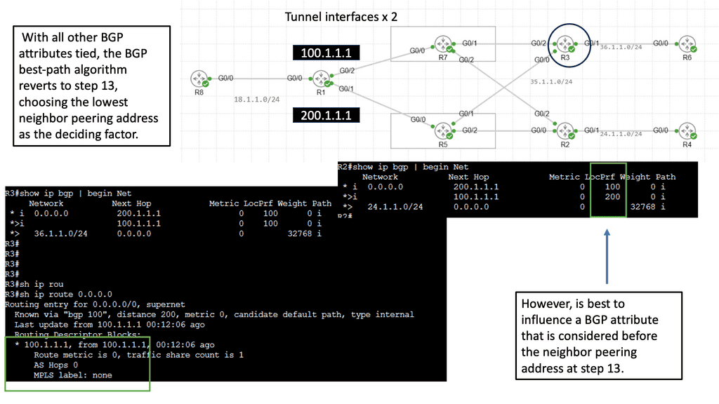
Border Gateway Protocol (BGP), the Internet’s glue, has several path selection flaws. The main drawback of BGP is the routing paradigm relating to the path-selection process. BGP default path selection is based on Autonomous System (AS) Path length; prefer the path with the shortest AS_PATH. It misses the shape of the network with its current path selection process. It does not care if propagation delay, packet loss, or link congestion exists. It resulted in long path selection and utilizing paths potentially experiencing packet loss.

Example: WAN SDN with Border6 

Border6 is a French company that started in 2012. It offers non-stop internet and an integrated WAN SDN solution, influencing BGP to perform optimum routing. It’s not a replacement for BGP but a complementary tool to enhance routing decisions. For example, it automates changes in routing in cases of link congestion/blackouts.

“The agile way of improving BGP paths by the Border 6 tool improves network stability” Brandon Wade, iCastCenter Owner.

As the Internet became more popular, customers wanted to add additional intelligence to routing. Additionally, businesses require SDN traffic optimizations, as many run their entire service offerings on top of it.

What is non-stop internet?

Border6 offers an integrated WAN SDN solution with BGP that adds intelligence to outbound routing. A common approach when designing SDN in real-world networks is to prefer that SDN solutions incorporate existing field testing mechanisms (BGP) and not reinvent all the wheels ever invented. Therefore, the border6 approach to influence BGP with SDN is a welcomed and less risky approach to implementing a greenfield startup. In addition, Microsoft and Viptela use the SDN solution to control BGP behavior.

Border6 uses BGP to guide what might be reachable. Based on various performance metrics, they measure how well paths perform. They use BGP to learn the structure of the Internet and then run their algorithms to determine what is essential for individual customers. Every customer has different needs to reach different subnets. Some prefer costs; others prefer performance.

They elect several interesting “best” performing prefixes, and the most critical prefixes are selected. Next, they find probing locations and measure the source with automatic probes to determine the best path. All these tools combined enhance the behavior of BGP. Their mechanism can detect if an ISP has hardware/software problems, drops packets, or rerouting packets worldwide. 

Thousands of tests per minute

The Solution offers the best path by executing thousands of tests per minute and enabling results to include the best paths for packet delivery. Outputs from the live probing of path delays and packet loss inform BGP on which path to route traffic. The “best path” is different for each customer. It depends on the routing policy the customer wants to take. Some customers prefer paths without packet loss; others wish to cheap costs or paths under 100ms. It comes down to customer requirements and the applications they serve.

**BGP – Unrelated to Performance**

Traditionally, BGP gets its information to make decisions based on data unrelated to performance. Broder 6 tries to correlate your packet’s path to the Internet by choosing the fastest or cheapest link, depending on your requirements.

They are taking BGP data service providers and sending them as a baseline. Based on that broad connectivity picture, they have their measurements – lowest latency, packets lost, etc.- and adjust the data from BGP to consider these other measures. They were, eventually, performing optimum packet traffic forwarding. They first look at Netflow or Sflow data to determine what is essential and use their tool to collect and aggregate the data. From this data, they know what destinations are critical to that customer.

BGP for outbound | Locator/ID Separation Protocol (LISP) for inbound

Border6 products relate to outbound traffic optimizations. It can be hard to influence inbound traffic optimization with BGP. Most AS behave selfishly and optimize the traffic in their interest. They are trying to provide tools that help AS optimize inbound flows by integrating their product set with the Locator/ID Separation Protocol (LISP). The diagram below displays generic LISP components. It’s not necessarily related to Border6 LISP design.

LISP decouples the address space so you can optimize inbound traffic flows. Many LISP uses cases are seen with active-active data centers and VM mobility. It decouples the “who” and the “where,” which allows end-host addressing not to correlate with the actual host location. The drawback is that LISP requires endpoints that can build LISP tunnels.

Currently, they are trying to provide a solution using LISP as a signaling protocol between Border6 devices. They are also working on performing statistical analysis for data received to mitigate potential denial-of-service (DDoS) events. More DDoS algorithms are coming in future releases.

Closing Points: On WAN SDN

At its core, WAN SDN separates the control plane from the data plane, facilitating centralized network management. This separation allows for dynamic adjustments to network configurations, providing businesses with the agility to respond to changing conditions and demands. By leveraging software to control network resources, organizations can achieve significant improvements in performance and cost-effectiveness.

One of the primary advantages of WAN SDN is its ability to optimize network traffic and improve bandwidth utilization. By intelligently routing data, WAN SDN minimizes latency and enhances the overall user experience. Additionally, it simplifies network management by providing a single, centralized platform to control and configure network policies, reducing the complexity and time required for network maintenance.
Summary: WAN SDN

In today’s digital age, where connectivity and speed are paramount, traditional Wide Area Networks (WANs) often fall short of meeting the demands of modern businesses. However, a revolutionary solution that promises to transform how we think about and utilize WANs has emerged. Enter Software-Defined Networking (SDN), a paradigm-shifting approach that brings unprecedented flexibility, efficiency, and control to WAN infrastructure.

Understanding SDN

At its core, SDN is a network architecture that separates the control plane from the data plane. By decoupling network control and forwarding functions, SDN enables centralized management and programmability of the entire network, regardless of its geographical spread. Traditional WANs relied on complex and static configurations, but SDN introduced a level of agility and simplicity that was previously unimaginable.

Benefits of SDN for WANs

Enhanced Flexibility

SDN empowers network administrators to dynamically configure and customize WANs based on specific requirements. With a software-based control plane, they can quickly implement changes, allocate bandwidth, and optimize traffic routing, all in real time. This flexibility allows businesses to adapt swiftly to evolving needs and drive innovation.

Improved Efficiency

By leveraging SDN, WANs can achieve higher levels of efficiency through centralized management and automation. Network policies can be defined and enforced holistically, reducing manual configuration efforts and minimizing human errors. Additionally, SDN enables the intelligent allocation of network resources, optimizing bandwidth utilization and enhancing overall network performance.

Enhanced Security

Security threats are a constant concern in any network infrastructure. SDN brings a new layer of security to WANs by providing granular control over traffic flows and implementing sophisticated security policies. With SDN, network administrators can easily monitor, detect, and mitigate potential threats, ensuring data integrity and protecting against unauthorized access.

Use Cases and Implementation Examples

Dynamic Multi-site Connectivity

SDN enables seamless connectivity between multiple sites, allowing businesses to establish secure and scalable networks. With SDN, organizations can dynamically create and manage virtual private networks (VPNs) across geographically dispersed locations, simplifying network expansion and enabling agile resource allocation.

Cloud Integration and Hybrid WANs

Integrating SDN with cloud services unlocks a whole new level of scalability and flexibility for WANs. By combining SDN with cloud-based infrastructure, organizations can easily extend their networks to the cloud, access resources on demand, and leverage the benefits of hybrid WAN architectures.

Conclusion:

With its ability to enhance flexibility, improve efficiency, and bolster security, SDN is ushering in a new era for Wide-Area Networks (WANs). By embracing the power of software-defined networking, businesses can overcome the limitations of traditional WANs and build robust, agile, and future-proof network infrastructures. It’s time to embrace the SDN revolution and unlock the full potential of your WAN.

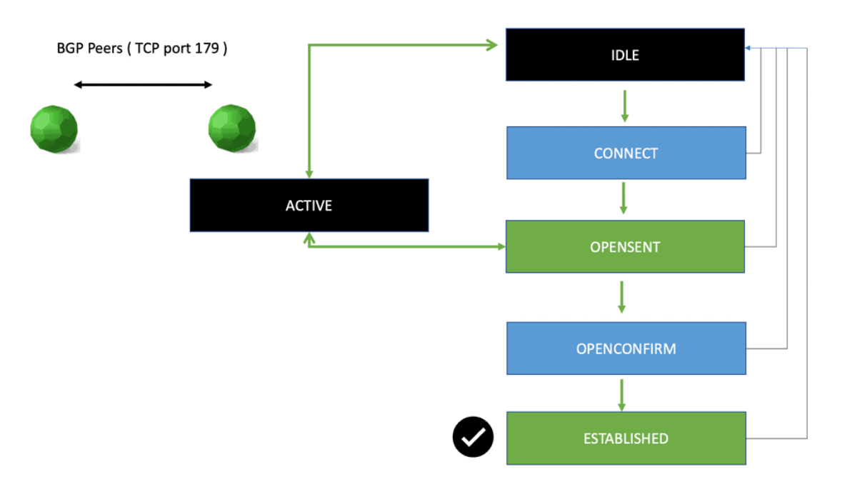
BGP neighbor states

BGP Port 179 exploit Metasploit

Network Security · Engineering Guide

Securing BGP Port 179: Session Exposure, Threat Detection and Defensive Engineering

Border Gateway Protocol (BGP) enables independently administered networks to exchange routing information. Its use of TCP port 179 provides the transport connection between BGP speakers, but a reachable port does not automatically mean that a BGP session can be established—or that the routing information exchanged is trustworthy.

For network engineers, the real security challenge is understanding the complete path from transport connectivity to an established BGP session, accepted routing updates and the forwarding decisions that affect traffic. A firewall rule, a successful TCP handshake and an Established BGP neighbor each provide different evidence. None should be treated as a complete assessment of routing security on its own.

This guide examines BGP port exposure from a defensive engineering perspective. We will explore how TCP and BGP establish a peer relationship, what session telemetry can reveal, how to investigate suspicious connection attempts or failed adjacencies, and how to apply layered controls at the network edge.

01 / SEE

Understand the session

Follow the TCP three-way handshake and BGP finite state machine. Separate transport establishment from BGP negotiation and routing exchange.

02 / OBSERVE

Collect meaningful evidence

Compare connection logs, firewall decisions, packet captures, neighbor states and routing updates to establish what actually happened.

03 / INVESTIGATE

Verify and strengthen defenses

Investigate failed sessions and unusual traffic, then assess peer restrictions, authentication, control-plane protection and route validation.

The engineering question

If TCP port 179 is reachable, how do you determine whether the BGP peer is legitimate, the session is behaving correctly, and the routes it exchanges meet your network's security policy?

BGP SECURITY · ENGINEERING GUIDE

Explore the TCP/179 Investigation

Follow the investigation from BGP session establishment to operational evidence, authorised security assessment and control-plane hardening. Select a stage to jump directly to its section introduction.

Engineering path: understand the session, examine the evidence, investigate safely, then verify the controls.
ENGINEERING VIEW · 01 / SEE

How TCP Port 179 Becomes a BGP Session

BGP uses TCP port 179 by default to establish a reliable transport connection between peers. TCP connectivity is only the beginning: the routers must also exchange BGP OPEN messages, negotiate session parameters and reach the Established state before normal route exchange can proceed.

IP reachability→ TCP handshake→ BGP OPEN→ Established
01 · SEE THE ARCHITECTURE

How TCP Port 179 Supports BGP

Border Gateway Protocol (BGP) exchanges reachability information between routers using a TCP connection. TCP port 179 is the standard BGP listening port, but understanding its role requires separating network reachability, transport connectivity, BGP session establishment and route exchange.

BGP is a control-plane protocol used to exchange routing information between autonomous systems and, through internal BGP (iBGP), among routers within the same autonomous system. Instead of sending each routing update as an independent, connectionless message, BGP uses TCP to provide a reliable, ordered byte stream between its peers.

By default, a BGP speaker listens for incoming connections on TCP port 179. The router initiating a connection will typically use an ephemeral source port and destination port 179. Return traffic normally uses source port 179 and the initiator's ephemeral destination port. The precise connection direction depends on which peer initiates the session; both eBGP and iBGP use TCP by default.

TCP port 179 The standard transport endpoint used by BGP speakers.
Reliable transport TCP handles ordered delivery, acknowledgements and retransmission.
Control plane BGP exchanges routes; the forwarding plane subsequently uses the installed forwarding entries.

From IP Reachability to Route Exchange

A working BGP session depends on several distinct stages. The peers must have IP connectivity to the intended addresses, and any required routing, firewall and security policies must permit the connection. Once TCP is established, BGP begins its own protocol-level negotiation.

1. IP Reachability The peer address is reachable through the underlying network.
2. TCP Handshake SYN, SYN-ACK and ACK establish the transport connection.
3. BGP Negotiation OPEN messages exchange AS numbers, identifiers and capabilities.
4. Route Exchange After reaching Established, peers can exchange routing updates subject to policy.

Conceptual sequence: the TCP handshake comes before BGP session negotiation. Successful completion of one stage does not guarantee completion of the next.

TCP Handshake Versus BGP Handshake

These are two separate processes. TCP establishes the communication channel; BGP uses that channel to negotiate and maintain the routing session. Confusing the two can lead to incorrect troubleshooting conclusions.

Stage What happens What success tells you
TCP three-way handshake SYN, SYN-ACK, ACK A TCP connection was established between the endpoints.
BGP OPEN Peers exchange protocol parameters and capabilities. BGP negotiation has begun; compatibility and configuration still matter.
KEEPALIVE Peers acknowledge successful negotiation and maintain session liveness. The session can progress toward or remain in Established.
UPDATE Reachability information and path attributes are exchanged. Routes can be advertised or withdrawn, subject to policy and protocol state.
NOTIFICATION A protocol error or other session-ending condition is reported. Inspect the notification and logs to identify the cause of termination.

BGP also supports extensions such as Route Refresh, which can allow a peer to request that routes be re-advertised without tearing down the session. The capabilities negotiated during OPEN determine which extensions are available.

Why Port 179 Matters for Security

Because BGP can influence how a network reaches external destinations, unauthorised access to the BGP control plane can have consequences beyond a single TCP connection. Depending on the weakness and the surrounding controls, risks can include session disruption, resource exhaustion and the acceptance of incorrect routing information.

However, an open TCP/179 port is not, by itself, proof of a vulnerability. A router may intentionally expose BGP to a configured peer while rejecting other sources. A port scan cannot establish whether the remote device is vulnerable, whether a peer is authorised, or whether route policy is safe.

Engineering takeaway: Validate the expected peer addresses, transport reachability, BGP session state and accepted routes as separate pieces of evidence. Treat TCP/179 exposure as a prompt to verify the design and controls—not as proof that an exploit exists.

With the transport and protocol layers clearly separated, the next step is to examine the evidence available during a real session failure: TCP connection behaviour, BGP neighbor state, logs and route information.

Engineering Evidence · Lab 01

TCP Port 179 → BGP Session

Trace the transport handshake, then the BGP OPEN exchange. Change the scenario to see why a reachable TCP endpoint does not automatically mean the BGP session will establish.
READY
Peer Topology · Simulated
0 / 8 events
◈
LOCAL ROUTER
192.0.2.1
AS 65001
◈
BGP PEER
192.0.2.2
AS 65002
TCP Transport
NOT STARTED
BGP FSM
Idle
Route Exchange
Not started
Start here: Step through the sequence. TCP connection establishment precedes BGP OPEN negotiation.
Session Evidence
Peer details
Local peer192.0.2.1
Configured remote peer192.0.2.2
Local AS65001
Expected remote AS65002
Observed remote AS65002
Session resultNot evaluated
Port Interpretation
TCP endpoints
Initiating sideEphemeral → TCP/179
Reply directionTCP/179 → Ephemeral
Transport protocolTCP
Control-plane protocolBGP
Remember: after establishment, packet direction and source/destination ports depend on which endpoint initiated the TCP connection.
Handshake & BGP Event Timeline
Select Step Forward
01
REACH
Confirm IP reachability to the configured peer address.
02
SYN
Initiator sends TCP SYN to the peer's destination port 179.
03
SYN-ACK
Peer responds to the initiating TCP endpoint.
04
ACK
TCP three-way handshake completes; a transport connection exists.
05
OPEN
BGP OPEN messages exchange AS and session parameters.
06
KEEPALIVE
BGP confirms successful negotiation and progresses toward Established.
07
ESTABLISHED
The peers can exchange routing information under their policies.
08
UPDATE
BGP UPDATE messages carry reachable prefixes and path attributes.
Diagnostic Readout
Lab telemetry
Current Observation
Ready to begin
Choose a scenario, then step through the simulated evidence.
Sequence Progress
Illustrative CLI Evidence
R1# show bgp summary
Neighbor state: not yet evaluated
Engineering question: Which layer has been proven to work — IP reachability, TCP transport, BGP negotiation, or route exchange?
ENGINEERING VIEW · 02 / OBSERVE

Use TCP, BGP State and Logs Together

A useful diagnosis correlates transport evidence with the BGP finite-state machine and routing information. A successful TCP connection does not establish that the BGP session is healthy or that expected prefixes are being accepted.

TCP telemetryConnection attempts, resets, timeouts and retransmissions.
BGP stateNeighbor state, uptime, last reset and negotiated parameters.
Route evidenceReceived prefixes, policy decisions and installed routes.
02 · OBSERVE THE EVIDENCE

How to Read TCP/179 and BGP Session Evidence

Effective BGP troubleshooting depends on correlating multiple sources of evidence. A TCP connection, a BGP neighbor state, a routing-table entry and a packet capture each reveal a different part of the session's health.

When a BGP peer is not establishing, avoid relying on a single command or an isolated packet capture. Start with the intended peer addresses and routing path, then compare transport-level behaviour with the BGP finite state machine (FSM), system logs and received route information. The aim is to identify the earliest stage that is not behaving as expected.

Four Evidence Sources

01 · TCP connection evidence

Look for connection attempts, completed handshakes, resets, retransmissions and timeouts. These observations help distinguish transport reachability from a BGP protocol problem.

02 · Neighbor state and uptime

Check the peer's FSM state, session duration, last reset reason and negotiated capabilities. Repeated resets may indicate an intermittent fault or a configuration mismatch.

03 · System logs and notifications

Correlate timestamps with connection failures, BGP notifications, authentication errors, configuration changes and interface events.

04 · Routing and policy evidence

Inspect received and accepted prefixes, route-policy decisions, best-path selection and installed routes. A healthy session does not guarantee that expected routes are accepted.

Interpret the BGP Finite State Machine

BGP uses a defined state machine to control session establishment. The current state narrows the investigation, but it should be interpreted alongside logs and transport evidence rather than treated as a complete diagnosis on its own.

Idle BGP is not actively progressing through session establishment. Inspect configuration, administrative status and relevant events.
Connect The router is attempting to establish the TCP connection. Connection failures or delays can keep the session from progressing.
Active The connection attempt has not succeeded as expected and BGP is retrying. Check reachability, filtering, source addresses and peer availability.
OpenSent The local BGP speaker has sent an OPEN message and is waiting for the peer's response. Inspect negotiation errors and peer compatibility.
OpenConfirm The OPEN exchange has progressed and BGP is waiting for a KEEPALIVE or other valid protocol event to complete establishment.
Established The BGP session is established. Continue checking route exchange, policy decisions and forwarding if traffic or reachability is still incorrect.
Important distinction: Active does not mean the BGP session is successfully established. It is commonly a retry state. Likewise, Established confirms the protocol session—not that every required prefix is being advertised, accepted or forwarded correctly.

Example: Read a Neighbor Summary

Network operating systems provide different command syntax, but a neighbor summary commonly exposes the remote peer, autonomous system, session state or uptime, and the number of prefixes received. The following is illustrative output, not a capture from a live router.

Illustrative CLI evidence
Neighbor        AS       State/PfxRcd
192.0.2.2       65002    24
192.0.2.3       65003    Active

In this simplified example, the first peer is established and has received 24 prefixes. The second peer is shown in Active, which warrants further investigation. The precise meaning of the summary field depends on the platform and command; confirm the detailed neighbor state before drawing a conclusion.

What a Packet Capture Can—and Cannot—Prove

A packet capture can help establish whether TCP traffic reaches the expected endpoint and whether the TCP handshake completes. If BGP negotiation begins, it may also expose OPEN messages, KEEPALIVE messages, UPDATEs or NOTIFICATIONs, subject to capture location, encryption or encapsulation elsewhere in the path, and platform behaviour.

Observed evidence Reasonable interpretation Next check
No response to connection attempts Possible filtering, unreachable peer, silent drop or unavailable endpoint. Check routing, ACLs, firewall counters and peer availability at both ends.
TCP reset The connection was reset; the packet alone may not identify the underlying cause. Correlate reset timing, endpoints, device logs and session state.
TCP established, then BGP negotiation fails Transport works, but BGP configuration or protocol negotiation may be failing. Inspect OPEN messages, AS configuration, authentication and notifications.
BGP Established, expected prefix missing The session is up, but advertisement, filtering, best-path selection or installation may differ from expectations. Check Adj-RIB-In, policy, best-path output and the routing/forwarding tables.

Correlate the Timeline

Use timestamps to align packet captures with neighbor-state changes, logs, interface events and configuration changes. For example, a peer reset immediately after a policy deployment suggests a different investigation path from a session that never completes the TCP handshake. Correlation helps build a defensible explanation instead of relying on assumptions.

  • Record the peer address, local source address and time window.
  • Identify the last successful stage: TCP connection, BGP negotiation or route exchange.
  • Compare both peers' logs where access is authorised.
  • Verify whether expected prefixes are received, accepted and installed.
  • Preserve relevant logs and captures before changing configuration.
Engineering takeaway: Diagnose the first failed stage, then verify the downstream consequences. Port 179 reachability, BGP session health and correct routing are related, but they are not interchangeable measures of success.

With the evidence correlated, the next stage is a controlled investigation: determine whether a peer is exposed as intended, isolate likely failure causes and assess security controls without disrupting production routing.

Engineering Evidence · Lab 02

Correlate BGP State, TCP Evidence and Logs

Investigate four simulated cases. Select a neighbor to inspect its state, compare packet evidence and logs, and determine whether the problem is transport, session negotiation or route policy.
READY
BGP Neighbor Table
Select a row for evidence
NeighborRemote ASState / PfxRcdUptimeInspect
192.0.2.26500224 prefixes02:14:38
192.0.2.365003Active—
192.0.2.46500418 prefixes01:07:12
Neighbor 192.0.2.2 · Established
The selected neighbor is established and reports 24 received prefixes in this illustrative table. Confirm route acceptance and installation separately.
Reading the table: on common network operating systems, a numeric value in State/PfxRcd usually represents the number of received prefixes; a state word such as Active represents a BGP FSM state. Check the platform's command reference.
Evidence Correlation
Simulated observations
TCP transportNot reviewed
BGP FSMNot reviewed
OPEN negotiationNot reviewed
Prefix evidenceNot reviewed
Likely fault domainAwaiting evidence
Packet Capture Lens
Waiting
CAPTURE> No packet evidence reviewed.
Method: correlate timestamps and endpoints. A capture from one interface may not show what happened elsewhere along the path.
Event Log
Chronological evidence
12:00:00
SIMULATION READY
Select an incident and advance the evidence review.
Investigation Workbench
0 / 4 checks
Current Finding
Choose an incident to begin
Use the evidence to identify the layer that is failing. Do not infer the root cause from a single state or packet.
Review Progress
Illustrative CLI
R1# show bgp summary
Review not started.
Engineering rule: TCP connectivity, BGP session state, and usable route installation are separate checks.
ENGINEERING VIEW · 03 / INVESTIGATE

Separate Reachability Problems from Security Risks

When a peer fails to establish, investigate the expected peer address, routing reachability, firewall rules, source-interface selection, autonomous system configuration and authentication. For security reviews, confirm that TCP/179 is exposed only where intended and assess controls using authorised, non-disruptive tests.

Investigation principle: An open port or a successful connection attempt does not prove that a vulnerability exists. Establish what should be reachable, compare it with observed behaviour, and validate findings against current vendor advisories.
03 · INVESTIGATE THE INCIDENT

Diagnosing BGP Port 179 Exposure and Session Failures

Finding TCP port 179 open is the beginning of a security investigation, not its conclusion. Engineers must determine whether the listener is expected, which systems can reach it, whether BGP peers authenticate and negotiate correctly, and whether routing policy limits the impact of incorrect announcements.

A useful investigation separates two questions. The first is operational: why is a BGP session failing or behaving unexpectedly? The second is security-focused: are the control-plane service and routing policies protected against unauthorised access, disruption or invalid route advertisements? These questions overlap, but they require different evidence and should be documented separately.

Start with the Expected Network Design

Before testing a device, identify the authorised peers, their expected source addresses, the intended session type and the network paths between them. An external BGP peer may connect across a provider link, while an internal peer may use a loopback address and rely on an underlying IGP or static routes. Multihop configurations can change the reachability and filtering requirements.

Peer identity

Confirm the configured neighbor address, local source address, remote AS and expected peering relationship.

Network reachability

Check the route to the peer address, return-path availability, interface status and any required multihop configuration.

Connection controls

Review router ACLs, firewalls and control-plane policies for permitted sources, destinations and TCP/179 traffic.

Session requirements

Compare authentication, AS settings, timers, capabilities and TTL-security requirements at both ends.

Diagnose the Earliest Failed Stage

Use the TCP and BGP evidence gathered in Section 2 to identify where the session stops progressing. Change one variable at a time where practical, and preserve the initial evidence before modifying production configuration.

Symptom Potential causes Investigation focus
Connection attempt times out Routing failure, packet filtering, silent drop or unavailable peer. Inspect routes, interface counters, ACL/firewall logs and captures at suitable points.
TCP connection is refused or reset No suitable listener, explicit rejection, active device policy or a connection being terminated. Correlate source/destination addresses, timestamps and logs on both endpoints where possible.
BGP repeatedly returns to Active TCP establishment is failing or the session cannot progress consistently. Check connection attempts, peer reachability, source address and transport filtering.
Failure during OPEN negotiation AS mismatch, incompatible parameters, authentication issues or protocol-level errors. Review detailed neighbor output, notification information and configuration at both ends.
Session is Established but routes are missing Route advertisement problems, inbound/outbound policy, best-path selection or installation issues. Inspect received prefixes, policy counters, advertised routes and routing/forwarding tables.
Do not overinterpret a reset: A TCP RST can terminate a connection, but seeing one does not establish that an attacker forged it. Confirm the packet path, sequence context where available, timing and endpoint logs before assigning a cause.

Assess Port 179 Exposure Safely

For an authorised security review, compare the observed service exposure with the approved network design. A listener that is reachable from an unexpected network may indicate an access-control gap, even if no software vulnerability is demonstrated. Conversely, a listener intentionally reachable by configured peers is not automatically a security defect.

Define the authorised scope Record the approved devices, source addresses, test window and permitted techniques. Avoid unapproved probing of third-party or provider infrastructure.
Establish the expected exposure Document which peer addresses should be able to reach TCP/179 and which source networks should be denied.
Use low-impact validation Review configuration, ACL counters, logs and service inventory first. If active connectivity checks are approved, keep them within scope and avoid disruptive connection floods or session-reset tests on production routers.
Validate findings independently Compare observations with vendor documentation and current security advisories. Record the evidence, impact, limitations and recommended remediation.
Retest after remediation Verify that authorised peers still operate correctly while unauthorised sources are blocked as designed. Confirm route exchange and forwarding remain healthy.

Where Metasploit Fits

Metasploit is a general-purpose penetration-testing framework. Its presence in a security workflow does not mean that a dedicated, applicable exploit exists for every protocol or open port. Before citing a specific BGP or TCP/179 module, verify that it exists in the current framework, understand the affected product and version, and consult the module's documentation.

An open port, a banner, a failed connection or a successful TCP handshake does not independently prove exploitability. A defensible finding should identify the actual weakness, affected component or configuration, the evidence supporting it, and the conditions required for impact. Where no vulnerability has been confirmed, report the observation accurately as exposure or a control gap rather than labelling it an exploit.

Understand the Routing Impact

BGP security is not limited to protecting TCP connections. A peer that is permitted to exchange routes can still advertise incorrect information if routing policy is weak or the peer is compromised. Route leaks and route origin hijacks are distinct routing problems; neither can be diagnosed simply by finding port 179 reachable.

  • Use explicit inbound and outbound prefix policy for each peer.
  • Apply appropriate AS-path policy and maximum-prefix limits.
  • Use RPKI Route Origin Validation where supported, while recognising that it validates the origin AS against a Route Origin Authorization—not the correctness of the entire AS path.
  • Monitor unexpected prefix changes, session resets and abnormal route volumes.
  • Preserve control-plane and routing logs to support incident reconstruction.
Engineering takeaway: A sound investigation moves from expected design to observed behaviour, then to verified cause and impact. Distinguish a reachability fault, a configuration error, an exposure gap and a confirmed vulnerability; each requires a different response.

Once the cause and exposure are understood, the final stage is to apply proportionate control-plane protections and prove that both session security and routing behaviour meet the intended design.

Engineering Evidence · Lab 03

Investigate BGP TCP/179 Exposure

Choose a simulated incident, step through the evidence, and distinguish a transport failure from a BGP negotiation problem. The goal is to diagnose from evidence—not assume that an open port proves a vulnerability.
Ready to investigate
Peer Connectivity
Evidence 0 / 5
◈
EDGE-R1
192.0.2.1 · AS65001
◈
EDGE-R2
192.0.2.2 · AS65002
TCP transportNot checked
BGP FSMUnknown
Route evidenceNot checked
Simulated Diagnostic Output
Illustrative only
Investigation ready. Select an incident, then press Step Forward to reveal evidence.
Evidence Summary
Updates per step
Peer identityUnverified
IP reachabilityUnverified
TCP handshakeUnverified
BGP negotiationUnverified
Route policyUnverified

Working diagnosis

Reveal the evidence in order. Start with expected peer identity and transport reachability before drawing conclusions about BGP or security.

Investigation Progress
0%
This lab uses a fictional lab topology and generated diagnostic results. It does not scan or connect to any real router.
Investigation Timeline
Evidence sequence
01
IDENTITY
Confirm the expected neighbor IP, remote AS and local source address.
02
REACH
Check the underlying IP path and relevant interface or route state.
03
TCP
Determine whether the TCP handshake completes or is filtered/reset.
04
BGP FSM
If TCP succeeds, inspect OPEN negotiation, peer parameters and logs.
05
ROUTES
If Established, check received prefixes and import/export policy.
Engineer’s Decision Checklist
Apply in order
01Validate the peer address, source interface/address and expected remote AS.
02Check IP reachability and firewall/ACL rules for the intended peer.
03Correlate TCP captures, BGP neighbor state and timestamped logs.
04Check authentication, TTL security where applicable, capabilities and timers.
05For missing routes, inspect prefix filters, route maps, max-prefix and RPKI policy.
ENGINEERING VIEW · 04 / CORRELATE & OPERATE

Harden the Control Plane and Prove Recovery

Protect BGP by limiting peer access, applying appropriate control-plane safeguards and enforcing route policy. After a change, verify both the session and the routes it exchanges; a neighbor showing Established is necessary, but not sufficient, evidence of correct routing.

Restrict accessPermit TCP/179 only from authorised peer addresses and protect the router control plane.
Strengthen sessionsUse supported peer authentication and suitable TTL-security protections where applicable.
Constrain routesApply prefix filters, AS-path policy and maximum-prefix limits; use RPKI origin validation where appropriate.
Verify outcomesCheck session state, accepted routes, best paths, logs and forwarding after remediation.
04 · CORRELATE & OPERATE

Hardening BGP Port 179 and Verifying Recovery

BGP security requires layered controls: restrict who can reach a peer, protect the router's control plane, constrain the routes exchanged and continuously verify that the resulting routing behaviour matches the network design.

TCP port 179 is the standard BGP transport endpoint, not a security boundary by itself. A resilient deployment combines network access controls, suitable peer authentication, routing policy, monitoring and tested operational procedures. The exact configuration depends on the network platform, topology, software release and peering requirements.

Layer 1: Restrict Access to BGP Peers

Permit BGP connections only from authorised peer addresses and on the interfaces or control-plane paths where they are expected. Use router access-control lists, firewall policy and platform-specific control-plane protection to reduce unnecessary exposure. Account for legitimate multihop sessions and loopback-sourced peers rather than assuming every neighbour connects directly over a single link.

Peer-specific filtering

Allow only the intended peer addresses and required TCP traffic. Review both inbound and outbound filtering where relevant to the architecture.

Control-plane protection

Use supported policing and rate-limiting mechanisms to protect the router's CPU from excessive control-plane traffic without disrupting legitimate routing.

Management separation

Keep administrative access on approved management paths, with strong authentication, least privilege and suitable logging.

Configuration discipline

Maintain an approved peer inventory and review changes to neighbor addresses, ACLs, route policy and session security.

Layer 2: Protect the BGP Session

Where supported, use an appropriate peer-authentication mechanism and configure it consistently at both ends. TCP MD5 is a legacy option found on many platforms; TCP Authentication Option (TCP-AO) is another mechanism where supported. These mechanisms protect TCP segments against certain forms of unauthorised injection, but they do not encrypt the session or replace access controls and routing policy.

Generalized TTL Security Mechanism (GTSM), often configured as TTL security, can also help protect suitable BGP sessions by restricting acceptable packet hop distance. It is particularly relevant to supported eBGP designs, but must be matched to the actual topology and multihop requirements.

Design caution: Authentication and TTL security must be supported and configured correctly at both ends. A mismatched key, incorrect TTL expectation or unsuitable ACL can prevent legitimate peers from establishing. Plan a controlled change and maintain a recovery path.

Layer 3: Control the Routes Being Exchanged

A secure transport connection does not guarantee that advertised routes are appropriate. Define which prefixes each peer is permitted to announce and which routes your network is allowed to export. Apply policy at the relevant import and export boundaries, and test it against both normal operation and failure scenarios.

Control Purpose Important limitation
Prefix filtering Restricts advertised or accepted network prefixes to an approved policy. Filters must reflect legitimate announcements and be maintained as the design changes.
AS-path policy Applies policy based on autonomous-system path attributes. It is not a cryptographic proof that every AS in the path is truthful.
Maximum-prefix limits Limits the number of prefixes accepted from a peer and can help contain unexpected route volume. Thresholds and exceed-limit actions need careful planning to avoid unintended session loss.
RPKI Route Origin Validation Checks whether a prefix and origin AS are authorised by a valid Route Origin Authorization (ROA). It does not validate the entire AS path or prevent every route leak or routing incident.
Monitoring and alerting Detects unexpected prefix changes, session resets, route-volume changes and policy events. Alerts need context and an operational response process to be useful.

Layer 4: Monitor for Changes That Matter

Establish a baseline for each peer: expected session state, normal uptime, received prefixes, accepted routes, route changes and reset frequency. Alerting on meaningful deviations can help identify misconfiguration, connectivity failures or suspicious behaviour before they become a larger routing incident.

  • Track neighbor state transitions and session reset reasons.
  • Monitor unexpected prefix advertisements, withdrawals and route-volume changes.
  • Correlate BGP events with interface, firewall and control-plane logs.
  • Protect logs and configuration records so incident timelines can be reconstructed.
  • Review current vendor security advisories and keep network software within supported maintenance policies.

Operational Verification After a Change

Hardening is incomplete until the change has been verified. Use a documented process to confirm that the intended access restrictions are active, legitimate peers still function, and route exchange and forwarding remain correct. Avoid using a single Established state as the only success criterion.

Record the baseline Capture peer states, prefix counts, relevant routes, control-plane counters and current policy before the change.
Apply the approved control Make the smallest practical change, following the platform's documented syntax and the site's change-management process.
Confirm session health Verify that expected peers reach Established, remain stable and show no unexplained resets or authentication failures.
Verify route policy Confirm expected prefixes are accepted and advertised, prohibited prefixes are rejected, and the selected routes match the design.
Check forwarding and monitoring Validate reachability through the forwarding plane, review alerts and counters, and confirm that unauthorised access is blocked as intended.
Document the result Record evidence, exceptions, residual risks and a tested rollback procedure. Close the incident only when the acceptance criteria are met.

From Port Exposure to Control-Plane Assurance

BGP security is a system property rather than a single port setting. Filtering limits exposure, session protections help resist certain forms of unauthorised interference, routing policy constrains accepted information, and monitoring helps operators detect and respond to change. Each layer addresses a different part of the risk.

Engineering takeaway: The objective is not simply to close TCP/179. It is to ensure that only intended peers can establish sessions, that route advertisements are governed by explicit policy, and that the network continues to converge and forward traffic correctly after changes or failures.

This completes the four-stage investigation: understand how BGP uses TCP port 179, observe the evidence, investigate exposure and failures, then harden the control plane and verify the operational result.

Engineering Evidence · Lab 04

Harden BGP Port 179 & Verify Recovery

Apply layered control-plane protections, then validate the session and routing evidence. This is a fictional operational simulation: the controls change the lab state only and do not configure or contact real routers.
Baseline loaded
BGP Control-Plane Path
Illustrative topology
◈
EDGE-R1
192.0.2.1 · AS65001
TCP / 179
◈
EDGE-R2
192.0.2.2 · AS65002
Peer sessionEstablished
Peer accessNeeds review
Route policyNeeds review
Verification Console
Generated lab output
Lab ready. 1. Choose a scenario. 2. Enable the relevant defensive controls. 3. Select Verify Configuration. 4. Verify the session and accepted route evidence.
Defensive Control Panel
Toggle controls
⌁
Peer ACL / Firewall
Permit TCP/179 only between approved peer addresses.
◉
Control-Plane Protection
Use suitable control-plane policing and rate limits.
◇
Session Protection
Use supported TCP authentication and suitable GTSM/TTL security for applicable peers.
⇄
Route Policy
Apply prefix and AS-path filters, max-prefix limits and appropriate RPKI ROV policy.
◷
Monitoring & Logging
Track neighbor resets, prefix changes, policy drops and control-plane events.
CONTROL COVERAGE 0 / 5
Verification Results
Check after changes
Approved peer accessNot verified
Control-plane resilienceNot verified
Session protectionNot verified
Route acceptance policyNot verified
Operational visibilityNot verified

Engineer’s assessment

Select a scenario, enable appropriate controls, and verify the result. A secure configuration should protect the control plane without blocking the intended BGP peer.

Recovery & Change Validation
Operational sequence
01
Capture the baselineRecord neighbor state, uptime, received prefixes, policy counters and relevant logs.
02
Apply approved changesRestrict peer access and add appropriate session, route-policy and monitoring controls.
03
Confirm BGP recoveryVerify the intended neighbor is Established and expected routes are accepted.
04
Validate forwardingConfirm routing-table and forwarding-table outcomes using approved test traffic.
05
Document and monitorSave the change record and watch for unexpected resets or prefix changes.
ENGINEERING RECAP · BGP SECURITY

BGP Port 179: Key Takeaways

TCP port 179 is the standard transport endpoint for BGP. Secure and reliable operation depends on more than port accessibility: engineers must validate session establishment, route policy, control-plane protections and forwarding outcomes together.

01 · TRANSPORT

TCP Is Only the First Step

A completed TCP handshake does not guarantee a successful BGP session. BGP must negotiate its parameters and reach Established.

02 · OBSERVABILITY

Correlate Multiple Evidence Sources

Compare packet captures, neighbor state, logs, received prefixes and installed routes to identify where behaviour diverges from expectations.

03 · INVESTIGATION

Exposure Is Not Proof of Exploitability

An open TCP/179 listener is not automatically vulnerable. Verify the expected access, product and version, configuration and supporting evidence.

04 · OPERATIONS

Protect Both Sessions and Routes

Restrict peer access, use appropriate session protections, apply routing policy and monitor for unexpected changes.

Control-plane verification checklist

✓Only authorised peer addresses can reach the intended BGP service.
✓Session authentication and TTL-security controls are appropriate to the topology.
✓Inbound and outbound route policies reflect the approved routing design.
✓Unexpected session resets and prefix changes are monitored and investigated.
✓RPKI origin validation is used where appropriate, with its limitations understood.
✓Post-change tests confirm session health, correct routes and forwarding.
Final engineering principle: Do not judge BGP security by whether TCP port 179 is open or closed alone. Judge it by whether the intended peers can communicate securely, route advertisements are governed by policy, and the network behaves correctly during normal operation and failure.
☕
Support Network Insight
Help support the development of interactive networking labs, BGP simulations, and educational content.
Support the Project