Understanding Transport SDN
Transport SDN is a network architecture that brings software-defined principles to the transport layer. Transport SDN enables centralized network management, programmability, and dynamic resource allocation by decoupling the control plane from the data plane. This empowers network operators to adapt to changing demands and optimize network performance swiftly.
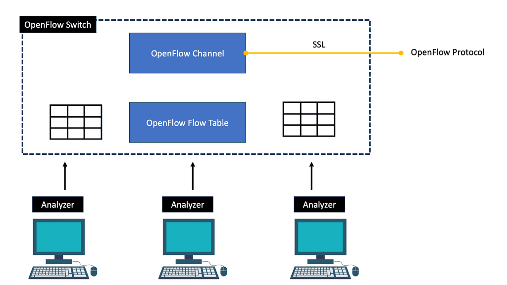
Understanding its key components is essential to comprehend the inner workings of Transport SDN. These include the Transport SDN Controller, which acts as the brain of the network, orchestrating and managing network resources. Additionally, the Transport SDN Switches play a crucial role in forwarding traffic based on the instructions received from the controller. Lastly, the OpenFlow protocol is the communication interface between the controller and the switches, facilitating seamless data flow.
Real-World Applications of Transport SDN
1 = Transport SDN has found wide-ranging applications across various industries. In the telecommunications sector, it enables service providers to efficiently provision bandwidth, optimize traffic routing, and enhance network resilience.
2 = Within data centers, Transport SDN simplifies network management, allowing for dynamic resource allocation and improved scalability. Moreover, Transport SDN facilitates intelligent traffic management in smart transportation and enables seamless vehicle connectivity.
3 = While Transport SDN offers immense potential, it also has its fair share of challenges. Organizations must address some hurdles to ensure interoperability between different vendor solutions, security concerns, and the need for skilled personnel.
4 = Looking ahead, the future of Transport SDN holds promise. Advancements in technologies like artificial intelligence and machine learning are anticipated to enhance the capabilities of Transport SDN further, unlocking new possibilities for intelligent network management.
Critical Benefits of Transport SDN:
1. Improved Network Efficiency: Transport SDN allows for intelligent traffic engineering, enabling network operators to optimize network resources and minimize congestion. Transport SDN maximizes network efficiency and improves overall performance by dynamically adjusting routes and bandwidth allocation based on real-time traffic conditions.
2. Enhanced Network Agility: With Transport SDN, network operators can rapidly deploy new services and applications. Leveraging programmable interfaces and APIs can automate network provisioning, eliminating manual configurations and reducing deployment times from days to minutes. This level of agility enables organizations to respond quickly to changing business needs and market demands.
3. Increased Network Scalability: Transport SDN provides a scalable and flexible solution for network growth. Network operators can scale their networks independently by separating the control and data planes and adding or removing network elements. This scalability ensures that the network can keep pace with the ever-increasing demands for bandwidth without compromising performance or reliability.
SDN data plane
Forwarding network elements (mainly switches) are distributed around the data plane and are responsible for forwarding packets. An open, vendor-agnostic southbound interface is required for software-based control of the data plane in SDN.
OpenFlow is a well-known candidate protocol for the southbound interface (McKeown et al. 2008; Costa et al. 2021). Each follows the basic principle of splitting the control and forwarding plane into network elements, and both standardize communication between the two planes. However, the network architecture design of these two solutions differs in many ways.
SDN control plane
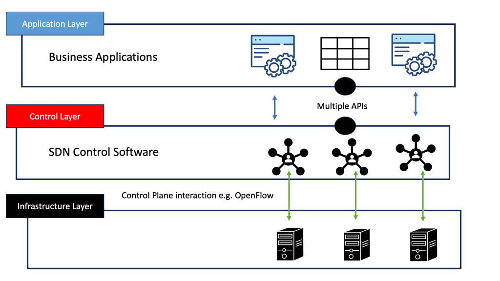
The control plane, an essential part of SDN architecture, consists of a centralized software controller that handles communications between network applications and devices. As a result, SDN controllers translate the requirements of the application layer down to the underlying data plane elements and provide relevant information to the SDN applications.
As the SDN control layer supports the network control logic and provides the application layer with an abstracted view of the global network, the network operating system (NOS) is commonly called the network operating system (NOS). In addition to providing enough information to specify policies, all implementation details are hidden from view.
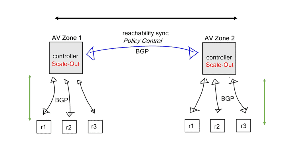
The control plane is typically logically centralized but is physically distributed for scalability and reliability reasons, as discussed in sections 1.3 and 1.4. The network information exchange between distributed SDN controllers is enabled through east-westbound application programming interfaces (APIs) (Lin et al. 2015; Almadani et al. 2021).
Despite numerous attempts to standardize SDN protocols, there has been no standard for the east-west API, which remains proprietary for each controller vendor. It is becoming increasingly advisable to standardize that communication interface to provide greater interoperability between different controller technologies in different autonomous SDN networks, even though most east-westbound communications occur only at the data store level and don’t require additional protocol specifics.
However, API east-westbound standards require advanced data distribution mechanisms and other special considerations.
Applications of Transport SDN:
1. Data Center Interconnect: Transport SDN enables seamless connectivity between data centers, allowing for efficient data replication, backup, and disaster recovery. Organizations can optimize resource utilization and ensure reliable and secure data transfer by dynamically provisioning and managing connections between data centers.
2. 5G Networks: Transport SDN plays a crucial role in deploying 5G networks. With the massive increase in traffic volume and diverse service requirements, Transport SDN enables network slicing, network automation, and dynamic resource allocation, ensuring efficient and high-performance delivery of 5G services.
3. Multi-domain Networks: Transport SDN facilitates the management and orchestration of complex multi-domain networks. A unified control plane enables seamless end-to-end service provisioning across different network domains, such as optical, IP, and microwave. This capability simplifies network operations and improves service delivery across diverse network environments.
SDN in the application plane
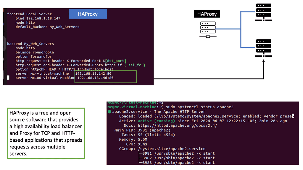
SDN applications are control programs that implement network control logic and strategies. In this higher-level plane, a northbound API communicates with the control plane. SDN controllers translate the network requirements of SDN applications into southbound commands and forwarding rules that dictate the behavior of data plane devices. In addition to existing controller platforms, SDN applications include routing, traffic engineering, firewalls, and load balancing.
In the context of SDN, applications benefit from the decoupling of the application logic from the network hardware along with the logical centralization of the network control to directly express the desired goals and policies in a centralized, high-level manner without being tied to the implementation and state-distribution details of the underlying networking infrastructure. Similarly, SDN applications consume network services and functions provided by the control plane by utilizing the abstracted network view exposed to them through the northbound interface.
SDN controllers implement northbound APIs as network abstraction interfaces that ease network programmability, simplify control and management tasks, and enable innovation. Northbound APIs are not supported by an accepted standard, contrary to southbound APIs
**Data and Control Planes**
The traditional ways to build routing networks are where the SDN revolution is happening. Networks started with tight coupling between data and control planes. The control plane was distributed, meaning each node had a control element and performed its control plane activities. SDN changed this architecture, centralized the control plane with a controller, and used OpenFlow or another protocol to communicate with the data plane. However, all control functions are handled by a central controller, which has many scaling drawbacks.
**Distribution and Centralized**
Therefore, we seem to be moving to a scalable hybrid control plane architecture. The hybrid control plane is a mixture of distributed and centralized controls. Centralization offers global visibility, better network operations, and optimizations. However, distributed control remains best for specific use cases, such as IGP convergence. More importantly, a centralized element introduces additional value to the Wide Area Network (WAN) network, such as network traffic engineering (TE) placement optimization, aka Transport SDN.
For additional pre-information, you may find the following posts helpful:
The two elements involved in forwarding packets through routers are a control function, which decides the route the traffic takes and its relative priority, and a data function, which delivers data based on control-function policy. Before the introduction of SDN, these functions were integrated into each network device. This inflexible approach requires all the network nodes to implement the same protocols. A central controller performs all complex functionality with SDN, including routing, naming, policy declaration, and security checks.
Transport SDN: The SDN Design
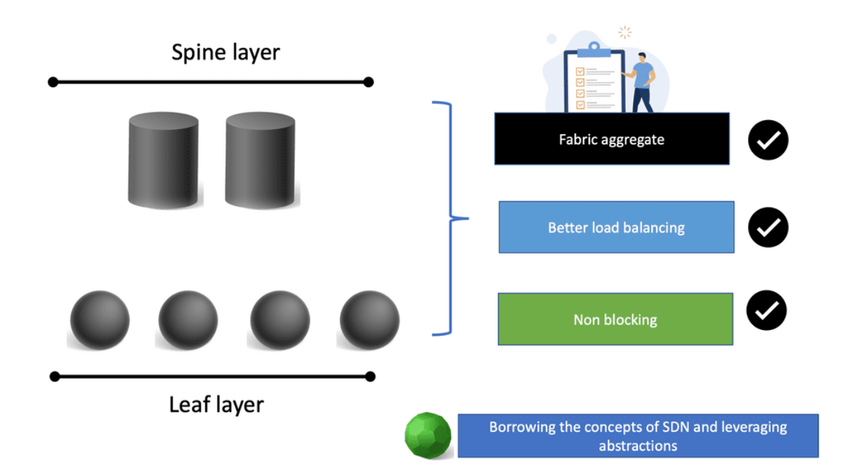
SDN has two buckets: the Wide Area Network (WAN) and the Data Centre (DC). What SDN is trying to achieve in the WAN differs from what it is trying to accomplish in the DC. Every point is connected within the DC, and you can assume unconstrained capacity.
A typical data center design is a leaf and spine architecture, where all nodes have equidistant endpoints. This is not the case in the WAN, which has completely different requirements and must meet SLA with less bandwidth. The WAN and data center requirements are entirely different, resulting in two SDN models.
The SDN data center model builds logical network overlays over fully meshed, unconstrained physical infrastructure. The WAN does not follow this model. The SDN DC model aims to replace, while the SD-WAN model aims to augment. SD-WAN is built on SDN, and this SD WAN tutorial will bring you up to speed on the drivers for SD WAN overlay and the main environmental challenges forcing the need for WAN modernization.
We can evolve the IP/MPLS control plane to a hybrid one. We go from a fully distributed control plane architecture where we maintain as much of the distributed control plane as it makes sense (convergence). At the same time, produce a controller that can help you enhance the control plane functionality of the network and interact with applications. Global optimization of traffic engineering offers many benefits.
**WAN is all about SLA**
Service Providers assure Service Level Agreement (SLA), ensuring sufficient capacity relative to the offered traffic load. Traffic Engineering (TE) and Intelligent load balancing aim to ensure adequate capacity to deliver the promised SLA, routing customers’ traffic where the network capacity is. In addition, some WAN SPs use point-to-point LSP TE tunnels for individual customer SLAs.
WAN networks are all about SLA, and there are several ways to satisfy them: Network Planning and Traffic Engineering. The better planning you do, the less TE you need. However, planning requires accurate traffic flow statistics to understand the network’s capabilities fully. An accurate network traffic profile sometimes doesn’t exist, and many networks are vastly over-provisioned.
A key point: Netflow
Netflow is one of the most popular ways to measure your traffic mix. Routers collect “flow” information and export the data to a collector agent. Depending on the NetFlow version, different approaches are taken to aggregate flows. Netflow version 5 is the most common, and version 9 offers MPLS-aware Netflow. BGP Policy Accounting and Destination Class Usage enables routers to collect aggregated destination statistics (limited to 16/64/126 buckets). BGP permits accounting for traffic mapping to a destination address.
For MPLS LSP, we have LDP and RSVP-TE. Unfortunately, LDP and RSVP-TE have inconsistencies in vendor implementations, and RSVP-TE requires a full mesh of TE tunnels. Is this good enough, or can SDN tools enhance and augment existing monitoring? Juniper NorthStar central controller offers friendly end-to-end analytics.
Transport SDN: Traffic Engineering
The real problem comes with TE. IP routing is destination-based, and path computation is based on an additive metric. Bandwidth availability is not taken into account. Some links may be congested, and others underutilized. By default, the routing protocol has no way of knowing this. The main traditional approaches to TE are MPLS TE and IGP Metric-based TE.
Varying the metric link moves the problem around. However, you can tweak metrics to enable ECMP, spreading traffic via a hash algorithm over-dispersed paths. ECMP suits local path diversity but lacks global visibility for optimum end-to-end TE. A centralized control improves the distribution-control insufficiency needed for optimal Multi-area/Multi-AS TE path computation.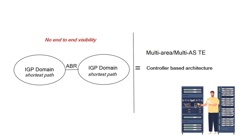
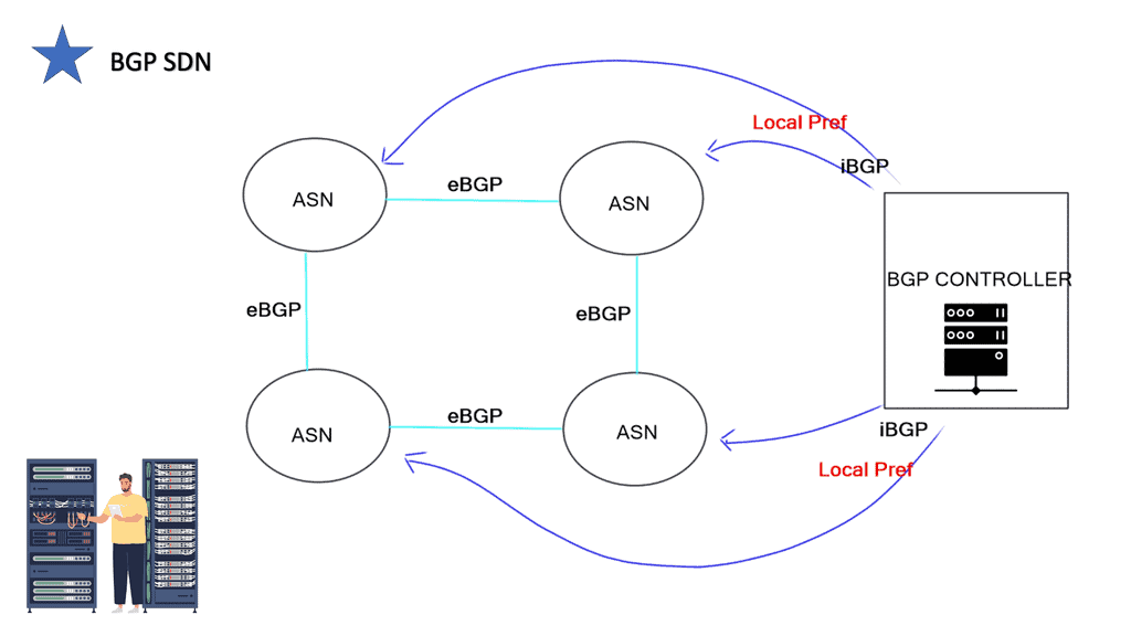
BGP-LS & PCEP
OpenDaylight is an SDN infrastructure controller that enhances the control plane, offering a service abstraction layer. It carries out network abstraction of whatever service exists on the controller. On top of that, there are APIs enabling applications to interface with the network. It supports BGP-LS and PCEP, two protocols commonly used in the transport SDN framework.
BGP-LS makes BGP an extraction protocol.
The challenge is that the contents of a Link State Database (LSDB) and an IGP’s Traffic Engineering Database (TED) describe only the links and nodes within that domain. When end-to-end TE capabilities are required through a multi-domain and multi-protocol architecture, TE applications require visibility outside one area to make better decisions. New tools like BGP-LS and PCEP combined with a central controller enhance TE and provide multi-domain visibility.
We can improve the IGP topology by extending BGP to BGP Link-State. This wraps up the LSDB in BGP transport and pushes it to BGP speakers. It’s a valuable extension used to introduce link-state into BGP. Vendors introduced PCEP in 2005 to solve the TE problem.
Initially, it was stateless, but it is now available in a stateful mode. PCEP address path computation uses multi-domain and multi-layer networks.
Its main driver was to decrease the complexity around MPLS and GMPLS traffic engineering. However, the constrained shortest path (CSPF) process was insufficient in complex typologies. In addition, Dijkstra-based link-state routing protocols suffer from what is known as bin-packing, where they don’t consider network utilization as a whole.
Closing Points on Transport SDN
Transport SDN is a specific application of the broader SDN technology that focuses on the management and optimization of transport networks. These networks are the backbone of any telecommunications infrastructure, responsible for carrying large volumes of data across vast distances. Transport SDN separates the control plane from the data plane, enabling network administrators to manage traffic dynamically and efficiently. This separation allows for improved network performance, reduced latency, and enhanced scalability.
One of the primary advantages of Transport SDN is its ability to enhance network agility. By providing a centralized control system, Transport SDN enables administrators to reconfigure the network in real time to adapt to changing demands. This flexibility is crucial in today’s fast-paced digital environment, where the need for quick adjustments is constant. Additionally, Transport SDN can lead to cost savings by optimizing resource usage and minimizing the need for manual interventions.
While Transport SDN offers numerous benefits, it is not without its challenges. Implementing this technology requires a significant investment in both time and resources. Organizations must carefully plan their migration to ensure a seamless transition. Security is another critical consideration, as the centralized nature of SDN can create potential vulnerabilities. It is essential for companies to adopt robust security measures to protect their network infrastructure.
Transport SDN is making its mark across various industries. In telecommunications, it is used to streamline operations and improve service delivery. Enterprises are leveraging Transport SDN to enhance their internal networks, facilitating better collaboration and communication. Additionally, data centers are employing this technology to manage traffic more effectively and ensure optimal performance for cloud-based services.