IPsec is a secure network protocol used to encrypt and authenticate data over the internet. It is a critical part of any organization’s secure network infrastructure, and it is essential to ensure fault tolerance. Optimum end-to-end IPsec networks require IPsec fault tolerance in several areas for ingress and egress traffic flows. Key considerations must include asymmetric routing, where a packet traverses from a source to a destination in one path and takes a different path when it returns to the source.
Understanding IPsec Fault Tolerance
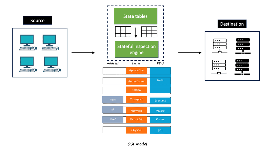
Before delving into fault tolerance, it’s essential to understand the foundation of IPsec. IPsec operates at the network layer, providing security features for IP packets through two main protocols: Authentication Header (AH) and Encapsulating Security Payload (ESP). These protocols ensure data authenticity and encryption, respectively, making IPsec a robust solution for secure communication. By implementing IPsec, organizations can protect sensitive data from interception and tampering, thereby maintaining trust and compliance with security standards.
**Section 1: The Challenges of Network Reliability**
Despite its security capabilities, IPsec, like any network system, is susceptible to failures. These can range from hardware malfunctions to configuration errors and network congestion. Such disruptions can lead to downtime, compromised data security, and financial losses. Therefore, ensuring network reliability through fault tolerance is not just an option but a necessity. Addressing these challenges involves implementing strategies that can detect, manage, and recover from failures swiftly and efficiently.
**Section 2: Strategies for Achieving IPsec Fault Tolerance**
To achieve IPsec fault tolerance, organizations can deploy several strategies. One common approach is redundancy, which involves having multiple instances of network components, such as routers and firewalls, to take over in case of failure. Load balancing is another technique, distributing traffic across multiple servers to prevent any single point of failure. Additionally, employing dynamic routing protocols can automatically reroute traffic, ensuring continuous connectivity. By integrating these strategies, businesses can enhance their network’s resilience and minimize downtime.
**Section 3: Implementing IPsec High Availability Solutions**
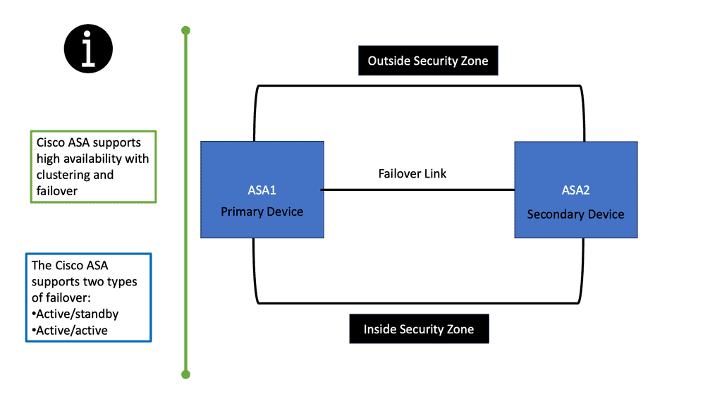
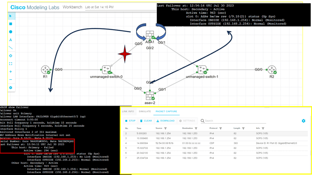
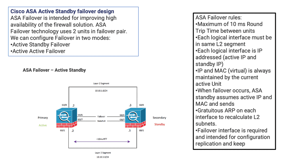
High availability (HA) solutions are vital for achieving IPsec fault tolerance. These solutions often include clustering and failover mechanisms that ensure seamless transition of services during outages. Clustering involves grouping multiple devices to function as a single unit, providing continuous service even if one device fails. Failover systems automatically switch to a backup system when a primary device goes down, maintaining uninterrupted network access. By leveraging these technologies, organizations can ensure that their IPsec implementations remain robust and reliable.
IPv6 Fault Tolerance Considerations:
A – : IPsec fault tolerance refers to the ability of an IPsec-enabled network to maintain secure connections even when individual components or devices within the network fail. Organizations must ensure continuous availability and protection of sensitive data, especially when network failures are inevitable. IPsec fault tolerance mechanisms address these concerns and provide resilience in the face of failures.
B – : One of the primary techniques employed to achieve IPsec fault tolerance is the implementation of redundancy. Redundancy involves the duplication of critical components or devices within the IPsec infrastructure. For example, organizations can deploy multiple IPsec gateways or VPN concentrators that can take over the responsibilities of failed devices, ensuring seamless connectivity for users. Redundancy minimizes the impact of failures and enhances the availability of secure connections.
- Redundancy and Load Balancing
One key approach to achieving fault tolerance in IPSec is through redundancy and load balancing. By implementing redundant components and distributing the load across multiple devices, you can mitigate the impact of failures. Redundancy can be achieved by deploying multiple IPSec gateways, utilizing redundant power supplies, or configuring redundant tunnels for failover purposes.
- High Availability Clustering
Another effective strategy for fault tolerance is the use of high availability clustering. By creating a cluster of IPSec devices, each capable of assuming the role of the other in case of failure, you can ensure uninterrupted service. High availability clustering typically involves synchronized state information and failover mechanisms to maintain seamless connectivity.
- Monitoring and Alerting Systems
To proactively address faults in IPSec, implementing robust monitoring and alerting systems is crucial. Monitoring tools can continuously assess the health and performance of IPSec components, detecting anomalies and potential issues. By configuring alerts and notifications, network administrators can promptly respond to faults, minimizing their impact on the overall system.
**Implementing IPsec Fault Tolerance**
1. Redundant VPN Gateways: Deploying multiple VPN gateways in a high-availability configuration is fundamental to achieving IPsec fault tolerance. These gateways work in tandem, with one as the primary gateway and the others as backups. In case of a failure, the backup gateways seamlessly take over the traffic, guaranteeing uninterrupted, secure communication.
2. Load Balancing: Load balancing mechanisms distribute traffic across multiple VPN gateways, ensuring optimal resource utilization and preventing overloading of any single gateway. This improves performance and provides an additional layer of fault tolerance.
3. Automatic Failover: Implementing automatic failover mechanisms ensures that any failure or disruption in the primary VPN gateway triggers a swift and seamless switch to the backup gateway. This eliminates manual intervention, minimizing downtime and maintaining continuous network security.
4. Redundant Internet Connections: Organizations can establish redundant Internet connections to enhance fault tolerance further. This ensures that even if one connection fails, the IPsec infrastructure can continue operating using an alternate connection, guaranteeing uninterrupted, secure communication.
IPsec fault tolerance is a crucial aspect of maintaining uninterrupted network security. Organizations can ensure that their IPsec infrastructure remains operational despite failures or disruptions by implementing redundancy, failover, and load-balancing mechanisms. Such measures enhance reliability and enable seamless scalability as the organization’s network grows. With IPsec fault tolerance, organizations can rest assured that their sensitive information is protected and secure, irrespective of unforeseen circumstances.
Load Balancing and Failover
Load balancing is another crucial aspect of IPsec fault tolerance. By distributing incoming connections across multiple devices, organizations can prevent any single device from becoming a single point of failure. Load balancers intelligently distribute network traffic, ensuring no device is overwhelmed or underutilized. This approach not only improves fault tolerance but also enhances the overall performance and scalability of the IPsec infrastructure.
Failover and high availability mechanisms play a vital role in IPsec fault tolerance. Failover refers to the seamless transition of network connections from a failed device to a backup device. In IPsec, failover mechanisms detect failures and automatically reroute traffic to an available device, ensuring uninterrupted connectivity. High availability ensures that redundant devices are constantly synchronized and ready to take over in case of failure, minimizing downtime or disruption.
Link Fault Tolerance
VPN data networks must meet several requirements to ensure reliable service to users and their applications. In this section, we will discuss how to design fault-tolerant networks. Fault-tolerant VPNs are resilient to changes in routing paths caused by hardware, software, or path failures between VPN ingress and egress points, including VPN access.
One of the primary rules of fault-tolerant network design is that there is no cookie-cutter solution for all networks. However, the network’s goals and objectives dictate VPN fault-tolerant design principles. There are many cases where economic factors influence the design more than technical considerations. Fault-tolerant IPSec VPN networks are also designed according to what faults they must be able to withstand
Backbone Network Fault Tolerance
In an IPSec VPN, the backbone network can be the public Internet, a private Layer 2 network, or an IP network of a single service provider. An organization other than the owner of the IPSec VPN may own and operate this network. A fault-tolerant network is usually built to withstand link and IP routing failures. The IP packet-routing functions the backbone provides are inherently used by IPSec protocols for transport. Often, IPsec VPN designers cannot control IP fault tolerance on the backbone.
**Advanced VPNs**
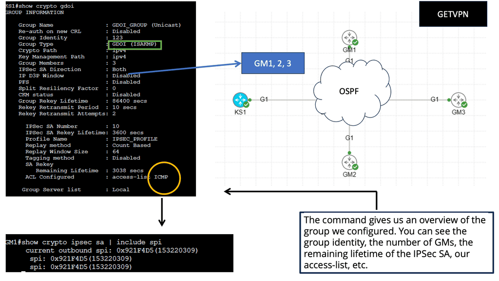
GETVPN:
GETVPN, an innovative technology by Cisco, provides secure and scalable data transmission over IP networks. Unlike traditional VPNs, which rely on tunneling protocols, GETVPN employs Group Domain of Interpretation (GDOI) to encrypt and transport data efficiently. This approach allows for flexible network designs and simplifies management.
Key Features and Benefits
Enhanced Security: GETVPN employs state-of-the-art encryption algorithms, such as AES-256, to ensure the confidentiality and integrity of transmitted data. Additionally, it supports anti-replay and data authentication mechanisms, providing robust protection against potential threats.
Scalability: GETVPN offers excellent scalability, making it suitable for organizations of all sizes. The ability to support thousands of endpoints enables seamless expansion without compromising performance or security.
Simplified Key Management: GDOI, the underlying protocol of GETVPN, simplifies key management by eliminating the need for per-tunnel or per-peer encryption keys. This centralized approach streamlines key distribution and reduces administrative overhead.
**Key Similarities & Differentiating Factors**
While GETVPN and IPSec have unique characteristics, they share some similarities. Both protocols offer encryption and authentication mechanisms to protect data in transit. Additionally, they both operate at the network layer, providing security at the IP level. Both can be used to establish secure connections across public or private networks.
Despite their similarities, GETVPN and IPSec differ in several aspects. GETVPN focuses on providing scalable and efficient encryption for multicast traffic, making it ideal for organizations that heavily rely on multicast communication. On the other hand, IPSec offers more flexibility regarding secure communication between individual hosts or remote access scenarios.
For additional pre-information, you may find the following helpful
Concept of IPsec
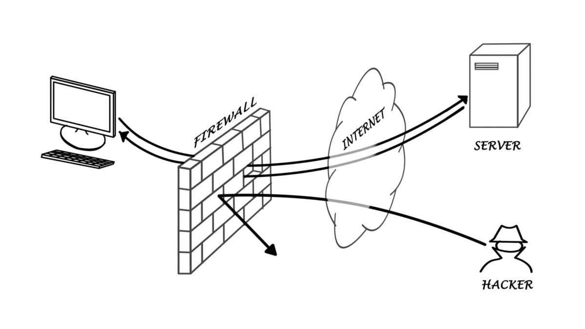
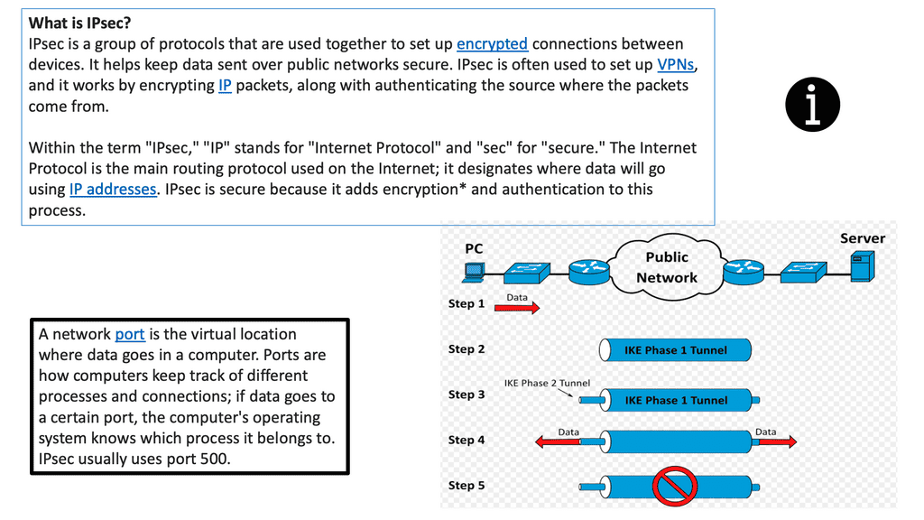
Internet Protocol Security (IPsec) is a set of protocols to secure communications over an IP network. It provides authentication, integrity, and confidentiality of data transmitted over an IP network. IPsec establishes a secure tunnel between two endpoints, allowing data to be transmitted securely over the Internet. In addition, IPsec provides security by authenticating and encrypting each packet of data that is sent over the tunnel.
IPsec is typically used in Virtual Private Network (VPN) connections to ensure secure data sent over the Internet. It can also be used for tunneling to connect two remote networks securely. IPsec is an integral part of ensuring the security of data sent over the Internet and is often used in conjunction with other security measures such as firewalls and encryption.
**IPsec session**
Several components exist that are used to create and maintain an IPsec session. By integrating these components, we get the required security services that protect the traffic for unauthorized observers. IPsec establishes tunnels between endpoints; these can also be described as peers. The tunnel can be protected by various means, such as integrity and confidentiality.
IPsec provides security services using two protocols, the Authentication Header and Encapsulating Security Payload. Both protocols use cryptographic algorithms for authenticated integrity services; Encapsulation Security Payload provides encryption services in combination with authenticated integrity.
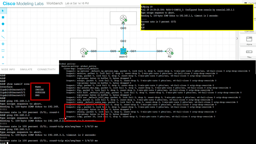
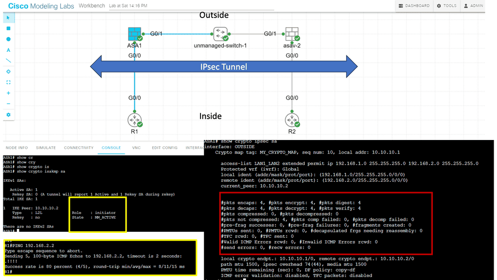
Guide on IPsec between two ASAs. Site to Site IKEv1
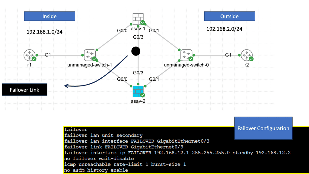
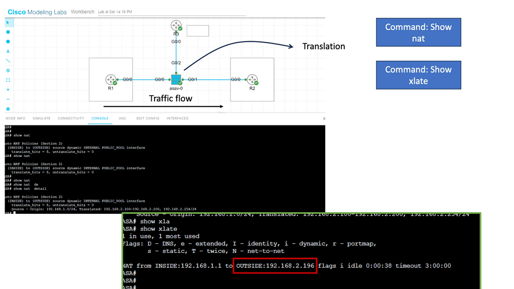
In this lab, we will look at site-to-site IKEv1. Site-to-site IPsec VPNs are used to “bridge” two distant LANs together over the Internet. So, we want IP reachability for R1 and R2, which are in the INSIDE interfaces of their respective ASAs. Generally, on the LAN, we use private addresses, so the two LANs cannot communicate without tunneling.
This lesson will teach you how to configure IKEv1 IPsec between two Cisco ASA firewalls to bridge two LANs. In the diagram below, you will see we have two ASAs. ASA1 and ASA2 are connected using their G0/1 interfaces to simulate the outside connection, which in the real world would be the WAN.
This is also set to the “OUTSIDE” security zone, so imagine this is their Internet connection. Each ASA has a G0/0 interface connected to the “INSIDE” security zone. R1 is on the network 192.168.1.0/24, while R2 is in 192.168.2.0/24. The goal of this lesson is to ensure that R1 and R2 can communicate with each other through the IPsec tunnel.
IPsec and DMVPN
DMVPN builds tunnels between locations as needed, unlike IPsec VPN tunnels that are hard coded. As with SD-WAN, it uses standard routers without additional features. However, unlike hub-and-spoke networks, DMVPN tunnels are mesh networks. Organizations can choose from three basic DMVPN topologies when implementing a DMVPN network.
The first topology is the hub-and-spoke topology. The second topology is the Fully Masked topology. Finally, the third topology is the hub-and-spoke with Partial Mesh topology. To create these DMVPN topologies, we have phases, such as DMVPN Phase 3, that are the most flexible, enabling a pull mesh of on-demand tunnels that can use IPsec for security.
Concept of Reverse Routing Injection (RRI)
For network and host endpoints protected by a remote tunnel endpoint, reverse route injection (RRI) allows static routes to be automatically injected into the routing process. These protected hosts and networks are called remote proxy identities.
The next hop to the remote proxy network and mask is the remote tunnel endpoint, and each route is created based on these parameters. Traffic is encrypted using the remote Virtual Private Network (VPN) router as the next hop.
Static routes are created on the VPN router and propagated to upstream devices, allowing them to determine the appropriate VPN router to send returning traffic to maintain IPsec state flows. When multiple VPN routers provide load balancing or failover, or remote VPN devices cannot be accessed via a default route, choosing the right VPN router is crucial. Global routing tables or virtual route forwarding tables (VRFs) are used to create routes.
The Networks Involved
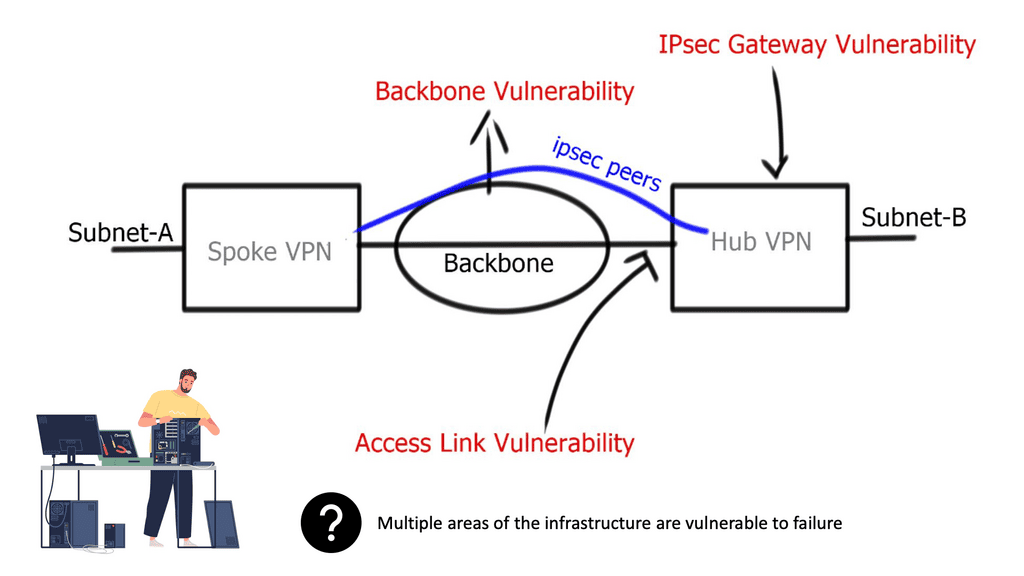
- Backbone network
IPsec uses an underlying backbone network for endpoint connectivity. It does not deploy its underlying packet-forwarding mechanism and relies on backbone IP packet-routing functions. Usually, the backbone is controlled by a 3rd-party provider, ensuring IPsec gateways trust redundancy and high availability methods applied by separate administrative domains.
- Access link
Adding a second link to terminate IPsec sessions and enabling both connections for IPsec termination improves redundant architectures. However, access link redundancy requires designers to deploy either Multiple IKE identities or Single IKE identities. Multiple IKE identity design involves two different peer IP addresses, one peer for each physical access link. The IKE identity of the initiator is derived from the source IP of the initial IKE message, and this will remain the same. Single IKE identity involves one peer neighbor, potentially terminating on a logical loopback address.
- Physical interface redundancy
Design physical interface redundancy by terminating IPsec on logical interfaces instead of multiple physical interfaces. Useful when the router has multiple exit points, and you do not want the other side to use multiple peers’ addresses. A single IPsec session is terminating on loopback instead of multiple IPsec sessions terminating on physical interfaces. You still require the crypto map configured on two physical interfaces. Issue the command to terminate IPsec on the loopback: “crypto map VPN local-address lo0.”
- A key point: Link failure
Phase 1 and 2 do not converge in the event of a single physical link failure. Convergence is based on an underlying network routing protocol. No IKE convergence occurs if one of the physical interfaces goes down.
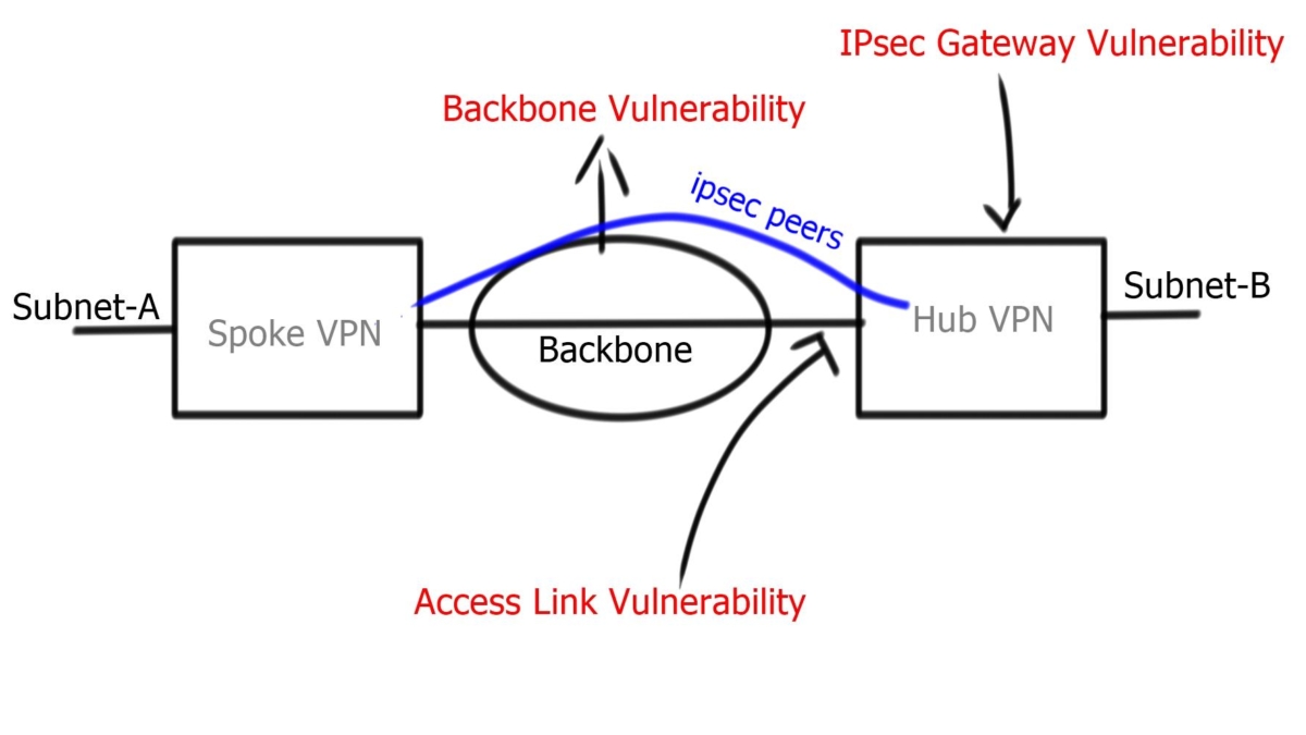
Asymmetric Routing
Asymmetric routing may occur in multipath environments. For example, in the diagram below, traffic leaves spoke A, creating an IPsec tunnel to interface Se1/1:0 on Hub A. Asymmetric routing occurs when return traffic flows via Se0:0. The effect is a new IPsec SA between Se0:0 and Spoke A, introducing additional memory usage on peers. Overcome this with a proper routing mechanism and IPsec state replication ( discussed later ).
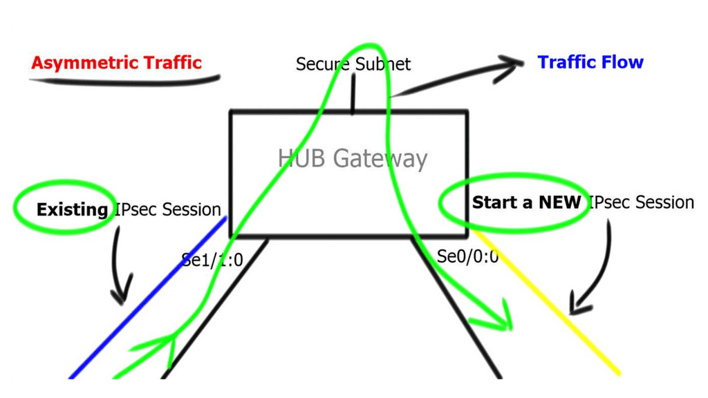
Design to ensure routing protocol convergence does not take longer than IKE dead peer detection. Routing protocols should not introduce repeated disruptions to IPsec processes. If you have control of the underlying routing protocol, deploy fast convergence techniques so that routing protocols converge faster than IKE detects a dead peer.
IPsec Fault Tolerance and IPsec Gateway
A redundant gateway involves a second IPsec gateway in standby mode. It does not have any IPsec state or replicate IPsec information between peers. Because either gateway may serve as an active gateway for spoke return traffic, you may experience asymmetric traffic flows. Also, due to the failure of the hub peer gateway, all traffic between sites drops until IKE and IPSec SAs are rebuilt on the standby peer.
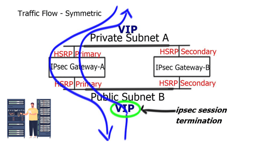
Routing mechanism at gateway nodes
A common approach to overcome asymmetric routing is to deploy a routing mechanism at gateway nodes. IPsec’s high availability can be incorporated with HSRP, which pairs two devices with a single VIP address. VIP address terminates IPsec tunnel. HSRP and IPsec work perfectly fine as long as the traffic is symmetric.
Asymmetric traffic occurs when the return traffic does not flow via the active HSRP device. To prevent this, enable HSRP on the other side of IPsec peers, resulting in Front-end / Back-end HSRP design model. Or deploy Reverse Route Injection ( RRI ), and static routes are injected only by active IPsec peer. You no longer need Dead Peer Detection ( DPD ) as you use VIP for IPsec termination. In the event of a node failure, the IPsec peer does not change. A different method to resolve the asymmetric problem is implementing Reverse Route Injection.
Reverse Route Injection (RRI)
RRI is a method that synchronizes return routes for the spoke to the active gateway. The idea behind RRI is to make routing decisions that are dependent on the IPsec state. For end-to-end reachability, a route to a “secure” subnet must exist with a valid network hop. RRI inserts a route to the “secure” subnet in the RIB and associates it with an IPsec peer. Then, it injects based on the Proxy ACL; matches the destination address in the proxy ACL.
RRI injects a static route for the upstream network.
HSRPs’ or RRI IPsec is limited because it does not carry any state between the two IPsec peers. A better high-availability solution is to have state ( Security Association Database ) between the two gateways, offering stateful failover.
Final Points: IPv6 Fault Tolerance
Fault tolerance in IPsec refers to the ability of the network to continue operating smoothly, even when certain components fail. This resilience is essential to prevent downtime, which can be costly and damaging to an organization’s reputation. By incorporating redundancy and failover mechanisms, networks can achieve higher levels of availability and reliability.
1. **Redundant Gateways**: Implementing multiple IPsec gateways ensures that if one fails, others can take over, maintaining seamless connectivity.
2. **Load Balancing**: Distributing IPsec traffic across multiple paths or gateways not only enhances performance but also boosts fault tolerance by preventing overload on a single component.
3. **Failover Mechanisms**: Automated failover processes can swiftly redirect traffic in case of a failure, reducing downtime and maintaining service continuity.
While IPsec fault tolerance offers numerous benefits, it also presents certain challenges. Network administrators must carefully configure and manage multiple devices and paths, which can introduce complexity. Additionally, ensuring that all redundant components are synchronized and up-to-date is essential to avoid security loopholes.
To maximize IPsec fault tolerance, consider the following best practices:
– Regularly test failover processes to ensure they work as intended.
– Keep all hardware and software components updated with the latest security patches.
– Monitor network performance continuously to identify potential issues before they escalate.
– Document network configurations and changes meticulously to facilitate troubleshooting.