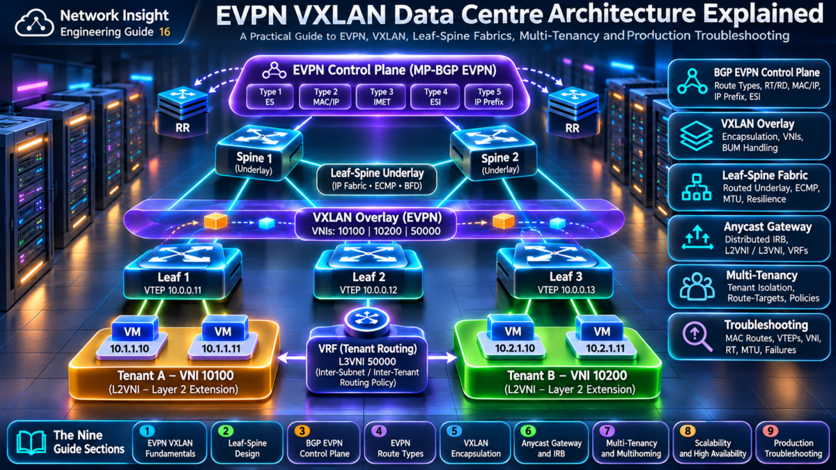
EVPN VXLAN Data Centre Architecture Explained
Modern data centres use routed leaf-spine fabrics and network overlays to deliver scalable workload connectivity, Layer 2 extension, Layer 3 segmentation, resilient forwarding and efficient east-west traffic movement. BGP EVPN provides the overlay control plane, while VXLAN carries encapsulated tenant traffic across an IP underlay.
This engineering guide explores the complete architecture of EVPN VXLAN networks, including VTEPs, VNIs, BGP EVPN route types, route reflectors, anycast gateways, integrated routing and bridging, multi-tenancy, convergence and real-world troubleshooting.
Interactive EVPN VXLAN Fabric Architecture
ANIMATED CONTROL + DATA PLANEIP Underlay — Routed Leaf-Spine Connectivity
Every leaf connects to both spines. The routed underlay provides IP reachability between VTEP loopback addresses, allowing VXLAN packets to traverse the fabric using ECMP.
What Makes EVPN VXLAN Different?
Routed IP Underlay
The physical fabric uses Layer 3 routing and ECMP instead of extending spanning-tree domains throughout the data centre.
BGP EVPN Control Plane
MP-BGP distributes overlay reachability information, including MAC/IP advertisements and other EVPN routes.
VXLAN Data Plane
VTEPs encapsulate tenant Ethernet frames inside UDP/IP packets and forward them across the underlay.
How an EVPN VXLAN Packet Crosses the Fabric
Consider Host A on Leaf 1 communicating with Host B on Leaf 2. Both workloads belong to the same Layer 2 virtual network, identified by VNI 10010.
BGP EVPN enables the originating VTEP to learn relevant remote MAC/IP reachability. The underlay then forwards the encapsulated packet toward the remote VTEP address.
What You Will Engineer in This Guide
The nine engineering sections progressively build the knowledge required to design, operate and troubleshoot production EVPN VXLAN fabrics.
Underlay and Overlay
Understand leaf-spine design, VTEPs, VNIs, IP routing and encapsulated forwarding.
BGP EVPN and Route Types
Investigate route advertisements, route reflectors, MAC/IP learning and EVPN policy.
Operations and Troubleshooting
Analyze anycast gateways, multi-tenancy, convergence, failures and forwarding anomalies.
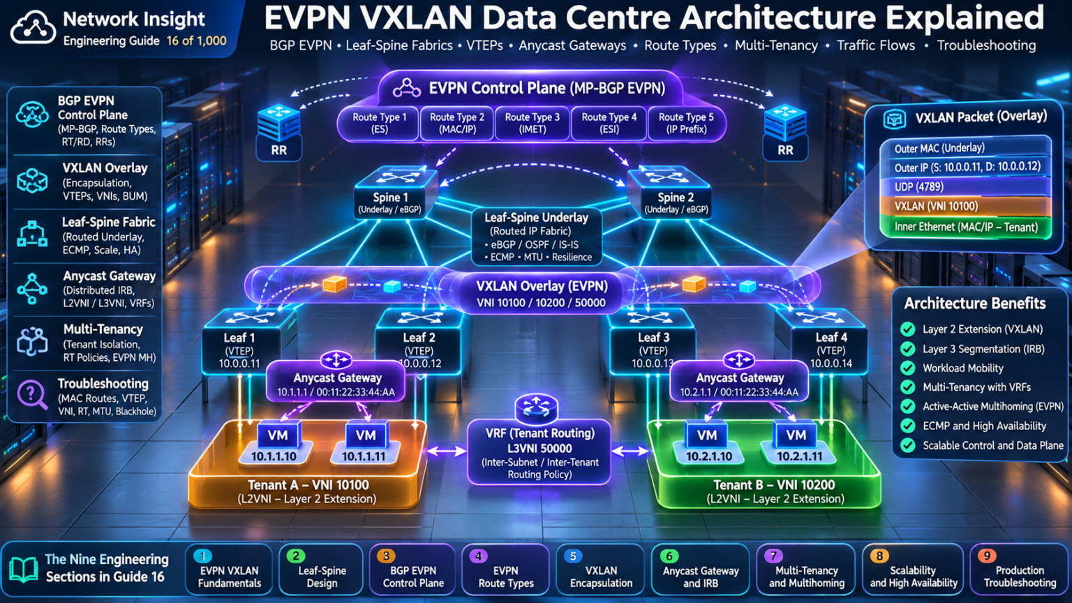
Explore the EVPN VXLAN Architecture
Navigate the nine engineering sections through an animated representation of the EVPN control plane, VXLAN overlay tunnels and routed leaf-spine fabric. Each section investigates a different part of the architecture, from foundational forwarding to production incident analysis.
EVPN VXLAN Architecture Fundamentals
Underlay, overlay, VTEPs, VNIs and architectural layers.
Leaf-Spine Underlay Network Design
eBGP, OSPF, IS-IS, ECMP, loopbacks and MTU.
BGP EVPN Control Plane Architecture
MP-BGP, route reflectors, RD, RT and next-hop resolution.
EVPN Route Types Explained
Type 1–5 routes, MAC/IP, IMET, Ethernet segments and prefixes.
VXLAN Encapsulation and VTEP Forwarding
UDP 4789, packet headers, MAC learning and BUM replication.
Anycast Gateways and Integrated Routing and Bridging
Distributed gateways, symmetric IRB, L2VNIs and L3VNIs.
Multi-Tenancy, Security and EVPN Multihoming
Tenant isolation, ESIs, all-active forwarding and DF election.
EVPN VXLAN Scalability and High Availability
ECMP, route scale, redundant control planes and convergence.
Production EVPN VXLAN Troubleshooting
Missing routes, VNI mismatches, MTU, packet captures and blackholes.
Understanding the EVPN VXLAN Architecture
EVPN VXLAN combines a routed IP fabric with a virtualized network overlay. The physical underlay provides IP reachability between tunnel endpoints, while the overlay enables tenant Layer 2 and Layer 3 connectivity across the fabric.
The architecture separates transport forwarding from tenant reachability. BGP EVPN distributes overlay control-plane information, while VXLAN encapsulates tenant Ethernet frames for forwarding across the IP underlay.
1.1 — Why Modern Data Centres Use EVPN VXLAN
Traditional Layer 2 data centre networks often rely on spanning-tree-based topologies. Although suitable for many environments, large extended broadcast domains can introduce operational and scaling challenges.
Routed leaf-spine architectures use multiple equal-cost paths and a Layer 3 underlay. EVPN VXLAN adds the ability to provide logical Layer 2 segments across those routed boundaries without requiring the physical fabric to behave as one large Layer 2 network.
Scalable Forwarding
The routed fabric supports multipath forwarding and avoids dependence on spanning tree for inter-switch fabric links.
Logical Segmentation
VNIs and VRFs enable separation of tenant broadcast domains and routed network contexts.
Control-Plane Learning
BGP EVPN distributes overlay reachability rather than relying exclusively on data-plane flooding.
1.2 — Interactive Underlay and Overlay Architecture
Select the architectural layer to inspect how physical IP routing, BGP EVPN signalling and VXLAN forwarding interact within the fabric.
EVPN VXLAN Layer Explorer
CONTROL PLANE + DATA PLANEIP Underlay
Routed leaf-spine links provide reachability between VTEP loopbacks. ECMP allows the underlay to select among multiple equal-cost paths.
1.3 — The Role of the VXLAN Tunnel Endpoint
A VXLAN Tunnel Endpoint, or VTEP, is responsible for encapsulating and decapsulating VXLAN traffic. In many data centre deployments, leaf switches act as VTEPs.
When a frame enters a VXLAN segment, the ingress VTEP identifies the relevant VNI and remote destination VTEP, then encapsulates the original Ethernet frame inside an outer UDP/IP packet.
1.4 — VXLAN Network Identifiers
A VXLAN Network Identifier, or VNI, is a 24-bit identifier used to distinguish VXLAN segments. This provides a much larger identifier space than the 12-bit VLAN ID.
In an EVPN VXLAN fabric, Layer 2 VNIs represent logical Ethernet segments, while Layer 3 VNIs may be associated with tenant VRFs in symmetric IRB designs.
Layer 2 VNI
Identifies a logical Ethernet broadcast domain across VTEPs. Used for same-subnet Layer 2 forwarding.
Layer 3 VNI
Commonly identifies a tenant routed overlay context associated with a VRF in symmetric IRB architectures.
1.5 — Interactive VXLAN Packet Encapsulation Inspector
Select a packet header to understand how the original Ethernet frame is carried through the routed fabric.
VXLAN Encapsulation Stack
PACKET STRUCTURE EXPLOREROuter Ethernet Header
The outer Ethernet header is used for local hop-by-hop forwarding across each physical link. Its source and destination MAC addresses may change as the packet traverses routed hops.
1.6 — BGP EVPN as the Overlay Control Plane
VXLAN defines a method of encapsulating Ethernet frames over an IP network, but does not by itself define a complete distributed control plane for learning remote endpoint reachability.
BGP EVPN provides a standards-based mechanism for advertising relevant overlay information, including MAC/IP reachability and other EVPN route types.
1.7 — Underlay Versus Overlay Responsibilities
| Component | Underlay | Overlay |
|---|---|---|
| Primary purpose | Transport IP packets between VTEPs. | Provide tenant network connectivity. |
| Routing | eBGP, OSPF, IS-IS or another supported design. | BGP EVPN reachability and VRF forwarding. |
| Identifiers | IP prefixes and next hops. | VNIs, MAC addresses, tenant IPs and route targets. |
| Forwarding | IP forwarding and ECMP. | VXLAN encapsulation and tenant forwarding. |
| Troubleshooting | Links, adjacencies, routing and MTU. | EVPN routes, VNI mapping and VTEP state. |
1.8 — Architecture Design Considerations
A production EVPN VXLAN design must account for underlay reachability, overlay control-plane scalability, tenant segmentation, MTU, endpoint mobility, failure recovery and operational visibility.
The underlay must support the additional encapsulation overhead introduced by VXLAN. Incorrect MTU configuration can cause packet loss or unexpected fragmentation behaviour.
VTEP Reachability
Verify stable IP reachability between participating VTEP loopback addresses.
VNI Consistency
Ensure intended overlay segments and tenant mappings are configured consistently.
Control-Plane Health
Validate BGP EVPN peerings, route advertisements, route-target policy and remote endpoint learning.
Engineering takeaway: EVPN VXLAN is built from three complementary elements: a routed IP underlay, a BGP EVPN overlay control plane and VXLAN data-plane encapsulation. Understanding how these components interact is the foundation for designing and troubleshooting modern data centre fabrics.
EVPN VXLAN Architecture Explorer
Explore a modern leaf-spine data centre fabric. Select endpoints, inspect overlay and underlay forwarding, observe VXLAN encapsulation, and investigate how VTEP reachability and VNI configuration affect traffic delivery.
Interactive EVPN VXLAN Fabric LaboratoryAnimated EVPN VXLAN leaf-spine architecture
Solid endpoint connections represent local attachment. Animated blue links represent routed underlay connectivity. The purple overlay arc illustrates logical VTEP-to-VTEP encapsulation rather than a physical tunnel cable.
Packet journey and forwarding decisions
Run a simulation to inspect the packet journey.
EVPN VXLAN engineering console
Designing the Routed Leaf-Spine Underlay
The IP underlay is the transport foundation of an EVPN VXLAN fabric. Its primary responsibility is to provide reliable Layer 3 connectivity between VTEP loopback addresses using predictable routing, redundant physical paths and fast convergence.
A well-designed underlay must support IP reachability, ECMP, stable loopback addressing, appropriate MTU, failure detection, routing policy and operational observability. Without a healthy underlay, the EVPN VXLAN overlay cannot forward traffic reliably.
2.1 — Leaf-Spine Network Architecture
A conventional two-tier leaf-spine fabric connects each leaf switch to every spine switch. The spines provide transit connectivity between leaf devices, while the leaves connect workloads, servers, firewalls or other network services.
This topology creates multiple equal-cost paths between leaf switches and avoids the need to extend Layer 2 switching across the fabric.
Spine Switches
Provide high-capacity routed transit paths between leaf switches. They do not need to terminate tenant VXLAN tunnels in a conventional leaf-VTEP design.
Leaf Switches
Connect endpoints and commonly act as VTEPs, performing overlay encapsulation, decapsulation and tenant forwarding.
IP Underlay
Carries routed traffic between VTEP loopbacks using IP forwarding and equal-cost paths.
2.2 — Interactive Leaf-Spine Underlay Explorer
Select a network condition to inspect routing, ECMP path selection, spine failure recovery and MTU requirements.
Routed Fabric Architecture and Failure Explorer
UNDERLAY ENGINEERINGIP Routing — VTEP Loopback Reachability
The underlay routing protocol advertises the VTEP loopback prefixes. Each leaf learns routes toward remote VTEPs through the available spine paths.
2.3 — Underlay Routing Protocol Selection
Common routed underlay designs use eBGP, OSPF or IS-IS. The selection depends on operational standards, hardware support, routing policy requirements and desired failure isolation.
| Protocol | Advantages | Considerations |
|---|---|---|
| eBGP | Explicit policy control, scalable routing domains and familiar BGP operations. | ASN planning, neighbor configuration and BGP path selection. |
| OSPF | Well-understood link-state routing with ECMP support. | Area design, LSDB scale and convergence tuning. |
| IS-IS | Link-state routing widely used in large routed networks. | Operational expertise and platform support. |
2.4 — eBGP Underlay Architecture
An eBGP underlay establishes routing sessions across point-to-point leaf-spine links. Each leaf advertises its loopback prefix, and the spines propagate reachability to other leaves.
BGP policy and ASN design must permit the intended routes to propagate. When using a common ASN across leaves, designers must account for AS-path loop prevention and platform-specific design patterns.
2.5 — ECMP and Equal-Cost Forwarding
Equal-Cost Multi-Path, or ECMP, allows a router to install multiple eligible next hops toward the same destination prefix.
In a leaf-spine fabric, ECMP can distribute traffic flows across multiple spine switches. Most deployments use flow-based hashing to reduce packet reordering.
Path Utilization
Multiple routed paths can carry traffic simultaneously, improving aggregate fabric utilization.
Resilience
When a path fails, forwarding can continue over remaining eligible next hops after failure detection and convergence.
2.6 — Loopback Addressing and VTEP Reachability
VTEP loopback addresses should remain stable independently of individual physical uplink failures.
The underlay must advertise and resolve these addresses. A healthy BGP EVPN session does not guarantee working VXLAN forwarding if the remote VTEP address is unreachable.
2.7 — BFD and Failure Detection
Bidirectional Forwarding Detection, or BFD, can provide rapid detection of forwarding path failures when supported and correctly integrated with the routing protocol.
Aggressive detection intervals should be tested against platform capabilities and operational stability. Incorrect tuning can cause unnecessary routing reconvergence.
2.8 — MTU Engineering for VXLAN
VXLAN introduces additional encapsulation headers around the original Ethernet frame. The routed underlay must support the resulting packet size.
For a typical VXLAN packet using outer IPv4 without additional options, the VXLAN, UDP and outer IPv4 headers add approximately 50 bytes beyond the original Ethernet frame. Link-layer overhead must also be considered when planning physical interface MTU.
2.9 — Failure Domains and Convergence
A resilient fabric should tolerate individual uplink and spine failures without losing all connectivity between healthy leaf switches.
Convergence behaviour depends on failure detection, routing protocol processing, route installation and forwarding-plane updates.
Leaf Uplink Failure
Traffic can use surviving paths when routing and forwarding converge correctly.
Spine Failure
Remaining spines provide alternate transit paths if the topology retains sufficient connectivity.
VTEP Reachability Loss
Overlay forwarding may fail even when the EVPN control plane retains previously learned endpoint routes.
2.10 — Production Underlay Troubleshooting
| Symptom | Likely domain | Investigation |
|---|---|---|
| Remote VTEP unreachable | Underlay routing | Inspect loopback routes, next hops and routing adjacencies. |
| Traffic loss after link failure | Convergence | Check BFD, routing updates and forwarding-plane installation. |
| Large packets fail | MTU | Validate encapsulated packet size across every fabric path. |
| Uneven path utilization | ECMP hashing | Review hash inputs, flow distribution and path eligibility. |
| Unexpected route rejection | BGP policy | Inspect AS paths, import/export policy and prefix filters. |
Engineering takeaway: The routed underlay is the foundation of every EVPN VXLAN fabric. Stable VTEP reachability, predictable ECMP, appropriate MTU, resilient topology and tested convergence behaviour are essential before overlay troubleshooting begins.
Leaf-Spine Fabric Topology Simulator
Investigate the routed underlay supporting EVPN VXLAN. Compare routing protocols, evaluate ECMP path diversity, inject physical and control-plane failures, and verify whether the fabric can transport encapsulated VXLAN packets between VTEP loopbacks.
Interactive IP Fabric Engineering LaboratoryLive routed leaf-spine topology
Underlay forwarding table
| Next hop | Path | State |
|---|---|---|
| Run calculation. | ||
This is a simplified ECMP forwarding model. Real eBGP multipath requires appropriate policy and multipath configuration. IGP and BGP path selection are not interchangeable.
Underlay engineering console
Understanding the BGP EVPN Control Plane
BGP EVPN provides the distributed control plane that allows VTEPs to exchange overlay reachability information across a routed data centre fabric. Rather than relying exclusively on data-plane flooding to discover remote endpoints, EVPN uses MP-BGP to advertise MAC addresses, IP addresses, Ethernet segment information and IP prefixes.
The EVPN control plane separates endpoint discovery, tenant routing policy and overlay signalling from the physical IP underlay. This enables scalable Layer 2 extension and integrated Layer 3 forwarding across distributed VTEPs.
3.1 — Why EVPN Uses MP-BGP
Multiprotocol BGP extends conventional BGP by supporting multiple address families. EVPN is represented using the L2VPN EVPN address family.
Instead of advertising only conventional IP unicast prefixes, BGP EVPN distributes route types that describe Ethernet and overlay reachability information.
Endpoint Discovery
Remote VTEPs learn MAC/IP reachability through EVPN advertisements.
Tenant Segmentation
Route targets control the import and export of EVPN routes between overlay routing contexts.
Scalable Distribution
Route reflectors can reduce the number of required iBGP sessions between EVPN speakers.
3.2 — Interactive BGP EVPN Control-Plane Explorer
Select a control-plane operation to visualize EVPN route advertisement, route reflection, route-target filtering and VTEP next-hop resolution.
BGP EVPN Route Distribution Explorer
MP-BGP EVPNEVPN MAC Advertisement
Leaf 1 advertises local MAC/IP reachability through BGP EVPN. The route reflector distributes the route to eligible EVPN clients, subject to BGP policy.
3.3 — EVPN Route Distinguishers
A Route Distinguisher, or RD, makes otherwise identical EVPN route identifiers unique within the BGP control plane.
Different VTEPs may advertise similar MAC/IP information. Unique RDs allow BGP to distinguish their advertisements as separate routes.
3.4 — Route Targets and Tenant Import Policy
A Route Target, or RT, is an extended community used to control route import and export between EVPN routing contexts.
A VTEP imports eligible EVPN routes according to its configured route-target policy. Incorrect route-target configuration can prevent endpoints from learning remote reachability.
Export RT
Applied to advertised EVPN routes to identify their intended import membership.
Import RT
Determines which EVPN routes a receiving routing context is eligible to import.
3.5 — EVPN Route Reflector Architecture
A full mesh of iBGP EVPN sessions becomes increasingly difficult to manage as the number of VTEPs grows.
Route reflectors reduce this session requirement by reflecting eligible routes between iBGP clients.
In EVPN VXLAN deployments, route reflectors commonly operate as control-plane distribution points and do not need to participate in tenant VXLAN data-plane forwarding.
3.6 — EVPN MAC/IP Advertisement Routes
EVPN Route Type 2 advertises MAC reachability and may include an associated IP address. This enables remote VTEPs to learn endpoint information through the control plane.
Depending on the EVPN service and implementation, these routes support remote MAC learning, MAC mobility handling and host reachability in integrated routing-and-bridging designs.
3.7 — BGP Next-Hop Resolution
Receiving an EVPN route does not automatically guarantee usable data-plane forwarding.
The receiving VTEP must resolve the route's next hop through the IP underlay. If the remote VTEP address is unreachable, overlay forwarding can fail.
EVPN Route Received
Confirm that the relevant EVPN route is present in the BGP table.
Route Imported
Verify the route target matches the intended tenant routing context.
Next Hop Resolved
Confirm that the underlay can reach the remote VTEP address.
3.8 — EVPN Control-Plane Versus Data-Plane Learning
EVPN distributes reachability information through the control plane, reducing the need to discover remote endpoints solely through flooding.
However, the behaviour of unknown unicast, broadcast and multicast traffic depends on the deployed EVPN service, VNI configuration and BUM replication design.
| Function | Control plane | Data plane |
|---|---|---|
| Endpoint discovery | BGP EVPN route advertisements. | Local MAC learning and applicable forwarding behaviour. |
| Remote reachability | EVPN route import and next-hop resolution. | VXLAN encapsulation toward remote VTEPs. |
| Tenant policy | Route targets and routing-context configuration. | VNI/VRF forwarding and enforced policy. |
| MAC mobility | EVPN mobility signalling where applicable. | Updated forwarding toward the current endpoint location. |
3.9 — Production BGP EVPN Troubleshooting
| Symptom | Likely cause | Investigation |
|---|---|---|
| Remote MAC missing | EVPN route not advertised or received. | Inspect EVPN BGP sessions and Type 2 routes. |
| Route received but not imported | Route-target mismatch. | Compare import/export RT configuration. |
| EVPN route present but forwarding fails | Unresolved VTEP next hop or data-plane issue. | Verify underlay reachability, VNI mapping and VXLAN forwarding. |
| Some VTEPs do not learn routes | Route reflection or policy issue. | Inspect RR client sessions, reflection rules and outbound policy. |
| Incorrect tenant route visibility | RT policy or VRF association error. | Validate tenant segmentation and route import policy. |
Engineering takeaway: BGP EVPN is the distributed overlay control plane that enables VTEPs to learn remote endpoint reachability. Route distinguishers provide uniqueness, route targets govern import policy, route reflectors improve session scalability, and underlay next-hop resolution connects the control plane to usable VXLAN forwarding.
BGP EVPN Control Plane Explorer
Examine how MP-BGP EVPN distributes MAC/IP advertisements between leaf VTEPs. Manipulate route reflectors, route targets, route distinguishers and session state to understand control-plane propagation and remote MAC learning.
Interactive BGP EVPN Engineering LaboratoryAnimated BGP EVPN control-plane topology
EVPN route advertisement and import table
| Attribute | Value |
|---|---|
| Run advertisement. | |
BGP EVPN engineering console
EVPN Route Types: How the Fabric Advertises Reachability
EVPN uses multiple BGP route types to communicate different kinds of overlay information. Each route type serves a particular architectural role, from endpoint discovery and BUM replication to multihoming and inter-subnet routing.
Understanding these routes is essential when troubleshooting missing MAC addresses, incorrect tenant forwarding, multicast replication, Ethernet segment failures and unavailable IP prefixes.
4.1 — The Five Core EVPN Route Types
| Type | Route name | Primary purpose |
|---|---|---|
| 1 | Ethernet Auto-Discovery | Ethernet segment discovery, mass withdrawal and multihoming-related signalling. |
| 2 | MAC/IP Advertisement | Advertise endpoint MAC addresses and optionally associated IP addresses. |
| 3 | Inclusive Multicast Ethernet Tag | Discover participants for BUM traffic distribution within an EVPN service. |
| 4 | Ethernet Segment | Discover multihoming peers and support designated-forwarder election. |
| 5 | IP Prefix | Advertise IP prefixes for EVPN-based routed overlay services. |
4.2 — Interactive EVPN Route-Type Explorer
Select any EVPN route type. The architecture diagram, example route information and explanation will update to show its role.
EVPN Route-Type Architecture Explorer
BGP L2VPN EVPNType 1 — Ethernet Auto-Discovery
Ethernet Auto-Discovery routes support EVPN multihoming, including per-ES and per-EVI advertisements. They are important for mass withdrawal and aliasing-related procedures.
4.3 — Type 1: Ethernet Auto-Discovery Routes
Type 1 routes advertise Ethernet Auto-Discovery information and play an important role in EVPN multihoming.
Per-Ethernet-Segment and per-EVI advertisements support procedures such as mass withdrawal and aliasing, depending on the EVPN service and deployment.
Multihomed Ethernet Segment Failure
When a PE loses connectivity to an Ethernet segment, withdrawal of relevant Ethernet Auto-Discovery reachability can help remote devices invalidate affected forwarding paths without waiting for individual MAC routes to age out.
4.4 — Type 2: MAC/IP Advertisement Routes
Type 2 routes are central to EVPN endpoint discovery. They advertise a MAC address and may include an associated IP address.
A receiving VTEP can use this information to determine where remote endpoints are reachable.
4.5 — Type 3: Inclusive Multicast Ethernet Tag Routes
Type 3 routes identify participants in an EVPN broadcast domain and support the construction of BUM traffic distribution state.
BUM stands for Broadcast, Unknown Unicast and Multicast. Depending on the deployment, the VXLAN fabric may use ingress replication or an appropriate multicast transport mechanism.
Ingress Replication
A VTEP can learn the other participating VTEPs for a broadcast domain and replicate relevant BUM frames toward the required remote tunnel endpoints.
4.6 — Type 4: Ethernet Segment Routes
Type 4 routes are used in EVPN multihoming to discover PEs attached to the same Ethernet segment.
They support designated-forwarder election procedures, which coordinate BUM forwarding toward multihomed Ethernet segments.
4.7 — Type 5: IP Prefix Advertisement Routes
Type 5 routes advertise IP prefixes through BGP EVPN and are important in routed overlay designs.
They allow IP prefix reachability to be distributed independently of advertising every endpoint as an individual MAC/IP route.
4.8 — Route-Type Dependencies
EVPN route types are not interchangeable. They provide complementary control-plane information for different service models.
Type 2 + Type 3
Type 2 routes advertise endpoint reachability. Type 3 routes support BUM distribution membership and replication state.
Type 1 + Type 4
Type 1 routes support Ethernet Auto-Discovery procedures, while Type 4 routes support Ethernet segment peer discovery and DF election.
Type 5
Type 5 routes advertise IP prefixes for routed EVPN services, subject to the configured resolution and forwarding model.
RD + RT + Next Hop
Route distinguishers, route targets and next-hop resolution determine uniqueness, import eligibility and forwarding usability.
4.9 — Production Route-Type Troubleshooting
| Symptom | Route type to inspect | Engineering investigation |
|---|---|---|
| Remote MAC missing | Type 2 | Verify MAC advertisement, RT import and remote VTEP reachability. |
| BUM replication incomplete | Type 3 | Inspect IMET routes and replication membership. |
| Multihoming convergence issue | Type 1 | Inspect Ethernet AD routes and withdrawals. |
| Unexpected DF behaviour | Type 4 | Inspect Ethernet segment routes, ESI and DF election parameters. |
| Remote IP prefix missing | Type 5 | Verify prefix advertisement, RT import and next-hop resolution. |
Engineering takeaway: EVPN Route Types 1–5 describe different parts of the overlay control plane. Type 1 supports Ethernet Auto-Discovery, Type 2 advertises MAC/IP reachability, Type 3 supports BUM distribution, Type 4 supports Ethernet segment discovery, and Type 5 advertises IP prefixes.
EVPN Route Type Investigation Lab
Decode EVPN control-plane advertisements, investigate route-target import policy and observe how different route types support MAC reachability, BUM replication, IP prefix routing and Ethernet-segment multihoming.
BGP EVPN Route Analysis LaboratoryAnimated EVPN route-distribution architecture
Decoded EVPN route attributes
| Field | Decoded value |
|---|---|
| Run a route investigation. | |
EVPN engineering console
How VXLAN Packets Travel Across the Data Centre Fabric
VXLAN enables Ethernet frames to traverse a routed IP fabric by encapsulating them inside UDP/IP packets. The ingress VTEP adds the VXLAN encapsulation, the underlay forwards the outer IP packet, and the egress VTEP removes the encapsulation before delivering the original frame.
Understanding this forwarding process is critical for diagnosing packet loss, incorrect VNI mapping, remote MAC reachability problems, MTU failures, BUM replication issues and ECMP path behaviour.
5.1 — VXLAN Encapsulation Architecture
VXLAN uses a 24-bit VNI to identify the logical overlay segment associated with the encapsulated Ethernet frame.
The outer IP header identifies the source and destination VTEPs, while the UDP destination port is conventionally 4789.
5.2 — Interactive VXLAN Packet Journey Explorer
Select a forwarding stage to inspect how an Ethernet frame becomes a VXLAN packet, crosses the routed underlay, and is delivered to the remote host.
VXLAN Packet Journey and BUM Replication
DATA PLANE EXPLORERStage 1 — Ingress Ethernet Frame
Host A sends an Ethernet frame toward Host B. Leaf 1 receives the frame and determines the corresponding local VLAN and Layer 2 VNI.
5.3 — VTEP Forwarding Decisions
Before encapsulating a frame, the ingress VTEP must determine whether the destination is local or remote.
For known remote unicast destinations, the VTEP uses its overlay forwarding information to identify the destination VTEP and appropriate VNI.
Local Forwarding
If the destination is locally attached, the switch forwards without remote VXLAN encapsulation.
Remote Unicast
A known remote destination is encapsulated toward the learned remote VTEP.
BUM Traffic
Broadcast, unknown unicast and multicast frames follow the configured replication and flooding rules.
5.4 — Remote MAC Learning
In a BGP EVPN deployment, remote MAC reachability can be learned through EVPN Type 2 route advertisements.
The receiving VTEP associates the remote MAC with the appropriate overlay forwarding context and remote VTEP.
5.5 — BUM Replication and Flooding
BUM traffic requires special handling because it may need to reach multiple participating VTEPs within a broadcast domain.
EVPN Type 3 routes can advertise replication membership for the corresponding EVPN service.
In ingress-replication deployments, the originating VTEP creates separate encapsulated copies for relevant remote VTEPs.
5.6 — ECMP Hashing and UDP Source Ports
VXLAN uses UDP encapsulation, which allows the outer UDP source port to provide entropy for ECMP hashing.
This helps the underlay distribute different encapsulated flows across multiple eligible paths.
Individual flows are typically kept on a consistent path to reduce packet reordering, although exact behaviour depends on the forwarding platform and hash configuration.
Outer IP Addresses
Source and destination VTEP IP addresses identify tunnel endpoints.
UDP Source Port
An entropy-derived UDP source port helps differentiate encapsulated flows.
Platform Hash Policy
Hardware determines which header fields influence ECMP path selection.
5.7 — VXLAN MTU and Encapsulation Overhead
The underlay must support the original frame plus the additional VXLAN, UDP and outer IP headers.
A conventional outer IPv4 VXLAN encapsulation adds approximately 50 bytes of overhead when counting the outer Ethernet header, without additional VLAN tags or optional headers.
5.8 — Packet Capture and Forwarding Validation
Packet captures provide valuable evidence when diagnosing VXLAN forwarding failures.
A capture taken on an underlay interface can reveal the outer VTEP addresses, UDP destination port and VNI.
5.9 — Production VXLAN Troubleshooting
| Symptom | Likely issue | Investigation |
|---|---|---|
| Remote host unreachable | Missing remote MAC or incorrect VTEP mapping. | Inspect EVPN Type 2 routes and overlay forwarding entries. |
| VXLAN packets dropped | MTU, filtering or unsupported encapsulation. | Validate packet size, ACLs and VTEP interface state. |
| Broadcast traffic missing | BUM replication membership issue. | Inspect EVPN Type 3 routes and replication lists. |
| Unexpected VNI | VLAN-to-VNI mapping error. | Compare ingress and egress overlay configuration. |
| Uneven fabric traffic | ECMP hash behaviour. | Inspect UDP source-port entropy and hardware hash policy. |
Engineering takeaway: VXLAN forwarding depends on correct endpoint learning, VNI mapping, remote VTEP resolution, encapsulation, underlay transport and decapsulation. When troubleshooting, inspect both the inner tenant frame and the outer VXLAN transport packet.
VXLAN Packet Encapsulation Simulator
Construct and inspect a VXLAN-encapsulated Ethernet frame. Explore VTEP selection, VXLAN headers, UDP port 4789, outer IP forwarding, BUM replication and remote decapsulation.
Interactive VXLAN Packet Engineering LaboratoryAnimated VXLAN packet forwarding topology
VXLAN packet header inspector
The outer IP header is routed through the underlay. The inner Ethernet frame remains encapsulated until the destination VTEP decapsulates the packet.
VXLAN forwarding console
Distributed Anycast Gateways and EVPN VXLAN IRB
EVPN VXLAN supports distributed Layer 3 gateways, allowing multiple leaf switches to provide the same default gateway IP address and virtual gateway MAC within a tenant subnet.
This architecture enables hosts to use a local first-hop gateway even when workloads are distributed across different VTEPs. Integrated Routing and Bridging, or IRB, combines Layer 2 overlay forwarding with Layer 3 routing between tenant subnets.
6.1 — Distributed Anycast Gateway Fundamentals
In a distributed anycast gateway design, multiple VTEPs provide equivalent gateway addresses for the same tenant subnet.
A host sends traffic to its default gateway, and the locally attached VTEP can perform the Layer 3 routing decision.
Local First Hop
Hosts can reach a default gateway on their directly attached leaf.
Distributed Routing
Layer 3 forwarding can occur at multiple VTEPs rather than a single central gateway.
Workload Mobility
Consistent gateway addressing can simplify host mobility within supported overlay designs.
6.2 — Interactive Anycast Gateway and IRB Explorer
Select a forwarding model to inspect same-subnet bridging, symmetric IRB, asymmetric IRB and a gateway-related failure scenario.
Anycast Gateway and IRB Architecture Explorer
DISTRIBUTED L3 GATEWAYSame-Subnet Layer 2 Forwarding
For same-subnet forwarding, traffic can remain in the Layer 2 overlay without requiring inter-subnet routing. The VTEPs bridge the tenant Ethernet frame across the corresponding L2VNI.
6.3 — Layer 2 VNIs and Layer 3 VNIs
A Layer 2 VNI identifies a logical Ethernet segment, while a Layer 3 VNI is commonly associated with a tenant VRF in symmetric IRB architectures.
Layer 2 Overlay Segment
Example: VNI 10010 for subnet 192.168.10.0/24. Supports tenant Ethernet forwarding.
Tenant Routed Context
Example: VNI 50000 associated with VRF BLUE. Supports routed overlay forwarding in a symmetric IRB design.
6.4 — Symmetric IRB Architecture
In symmetric IRB, the ingress VTEP routes the packet into the tenant routed overlay, and the egress VTEP routes it from that overlay toward the destination subnet.
The routed overlay commonly uses a Layer 3 VNI associated with the tenant VRF.
6.5 — Asymmetric IRB Architecture
In asymmetric IRB, the ingress VTEP performs inter-subnet routing and then bridges the packet across the destination Layer 2 VNI.
This design generally requires the ingress VTEP to have the relevant destination subnet's L2VNI and associated forwarding context.
6.6 — Symmetric Versus Asymmetric IRB
| Characteristic | Symmetric IRB | Asymmetric IRB |
|---|---|---|
| Routing model | Ingress and egress VTEPs participate in routed forwarding. | Ingress VTEP performs inter-subnet routing. |
| Transit VNI | Typically uses a tenant L3VNI. | Uses the destination subnet's L2VNI. |
| Subnet distribution | Does not require every leaf to instantiate every tenant L2VNI. | Ingress leaf generally needs relevant destination L2VNI state. |
| Scalability | Often preferred for larger distributed routed overlays. | Can be practical in smaller or constrained designs. |
| Operational focus | VRF, L3VNI, EVPN routes and next-hop resolution. | Destination L2VNI, MAC learning and local routing state. |
6.7 — Tenant VRFs and Routing Isolation
Virtual Routing and Forwarding instances provide independent Layer 3 routing tables for different tenants.
A tenant VRF can contain multiple subnets and their corresponding Layer 2 VNIs.
6.8 — EVPN Routes Used in IRB
EVPN Type 2 routes can advertise host MAC/IP reachability. Type 5 routes can advertise routed IP prefixes.
The exact EVPN route combination and next-hop resolution model depend on the selected IRB architecture and platform implementation.
Host Reachability
Advertises MAC/IP endpoint information used by relevant EVPN forwarding procedures.
IP Prefix Reachability
Advertises routed prefixes for supported EVPN Layer 3 services.
Remote VTEP
Requires usable transport reachability and correct overlay forwarding state.
6.9 — Production IRB Troubleshooting
| Symptom | Likely issue | Investigation |
|---|---|---|
| Same-subnet traffic works, inter-subnet fails | VRF routing, IRB configuration or L3VNI issue. | Inspect tenant routing table, gateway interfaces and L3VNI mapping. |
| Host cannot reach default gateway | Anycast gateway or local VLAN/VNI mapping issue. | Verify gateway IP/MAC, SVI state and local host attachment. |
| Traffic fails between remote subnets | Missing EVPN reachability or unresolved next hop. | Inspect Type 2/5 routes, route targets and VTEP reachability. |
| Asymmetric IRB fails for selected subnets | Missing destination L2VNI or MAC state. | Verify required L2VNIs and destination forwarding entries. |
| Unexpected cross-tenant connectivity | Incorrect VRF association or route leaking. | Review tenant VRFs, route targets and security policy. |
Engineering takeaway: Distributed anycast gateways place the default gateway close to workloads, while IRB provides routing between tenant subnets. Symmetric IRB commonly uses a tenant L3VNI for routed overlay transport, whereas asymmetric IRB routes at ingress and bridges across the destination L2VNI.
Anycast Gateway and IRB Traffic Flow Simulator
Investigate distributed anycast gateways, symmetric and asymmetric IRB, tenant VRFs, L2VNIs and L3VNIs. Follow a packet from a source workload through ingress routing, VXLAN encapsulation, remote decapsulation and destination delivery.
EVPN VXLAN Distributed Gateway LaboratoryAnimated distributed anycast gateway architecture
IRB packet journey and forwarding table
| Stage | Forwarding operation |
|---|---|
| Run the IRB simulation. | |
Anycast gateway engineering console
Tenant Isolation, Security and Resilient EVPN Multihoming
EVPN VXLAN enables multiple logical networks to share the same physical leaf-spine infrastructure while maintaining separate Layer 2 and Layer 3 forwarding contexts.
Multi-tenancy is achieved through combinations of VNIs, VRFs, route-target policy and explicit security controls. EVPN multihoming adds resilience by allowing a device or Ethernet segment to connect to multiple provider edge devices.
7.1 — Multi-Tenant EVPN VXLAN Architecture
A tenant may have one or more Layer 2 VNIs associated with its subnets and a Layer 3 VNI associated with its routed VRF in symmetric IRB designs.
Separate VRFs maintain independent routing tables. Route targets control the import of EVPN reachability into the intended overlay contexts.
7.2 — Interactive Multi-Tenant and Multihoming Explorer
Select a scenario to inspect tenant isolation, all-active multihoming, single-active forwarding and Ethernet segment failure recovery.
EVPN Tenant Isolation and Multihoming Explorer
EVPN SECURITY + RESILIENCETenant Isolation
Separate tenant VRFs, VNIs and route-target policies restrict which overlay routes are imported into each forwarding context.
7.3 — Route Targets and Tenant Isolation
Route targets determine which EVPN routes are imported into particular tenant contexts.
Incorrect route-target configuration can create unintended route visibility or prevent legitimate remote reachability.
RT 65000:50000
Imported by the intended BLUE routed overlay contexts according to their configured policy.
RT 65000:60000
Imported by the intended GREEN routed overlay contexts according to their configured policy.
7.4 — Security Boundaries in EVPN VXLAN
VRFs and VNIs provide forwarding separation, but they should not be treated as a complete security architecture.
Production deployments often require additional controls such as ACLs, firewalls, segmentation policy, route-leaking governance and management-plane protection.
VRF Isolation
Maintain separate routing tables for tenants.
Policy Enforcement
Apply appropriate ACLs, firewalls and inter-tenant traffic controls.
Control-Plane Protection
Protect BGP sessions, management access and route advertisement policy.
7.5 — Ethernet Segment Identifiers
EVPN multihoming uses an Ethernet Segment Identifier, or ESI, to identify an Ethernet segment attached to multiple EVPN provider edge devices.
Participating PEs advertise the relevant Ethernet segment information using EVPN control-plane routes.
7.6 — All-Active EVPN Multihoming
In all-active multihoming, multiple PEs attached to an Ethernet segment can participate in forwarding, subject to the EVPN service and forwarding procedures.
EVPN multihoming mechanisms help coordinate remote reachability, aliasing and loop prevention.
Redundant Forwarding Paths
Multiple participating PEs can provide forwarding paths for the same Ethernet segment. BUM forwarding toward the segment is coordinated through designated- forwarder procedures.
7.7 — Single-Active EVPN Multihoming
In single-active multihoming, only one PE is designated to forward relevant traffic for an Ethernet segment or service at a time, according to the applicable EVPN procedures.
This can simplify forwarding behaviour for certain attached systems, while potentially limiting simultaneous path utilization.
7.8 — Designated Forwarder Election
The Designated Forwarder, or DF, is selected to coordinate forwarding of relevant BUM traffic from the EVPN network toward a multihomed Ethernet segment.
EVPN Type 4 routes support Ethernet segment peer discovery, which contributes to DF election.
DF election algorithms and operational behaviour vary according to supported EVPN standards and platform implementations.
7.9 — Multihoming Failure Recovery
When a participating PE or attachment fails, EVPN control-plane updates and local forwarding changes can redirect traffic toward remaining usable paths.
Recovery depends on failure detection, Ethernet segment signalling, routing convergence and correct forwarding-plane updates.
| Failure | Expected design behaviour | Investigation |
|---|---|---|
| One CE-facing link fails | Surviving attachment may continue forwarding. | Check ESI membership, interface state and EVPN withdrawals. |
| One PE fails | Remaining PE may preserve service connectivity. | Inspect Type 1/4 routes and convergence. |
| Unexpected duplicate BUM traffic | DF procedures should prevent inappropriate duplicate delivery. | Inspect DF election state and Ethernet segment configuration. |
| Remote traffic blackholes | Forwarding should avoid unavailable PE paths after convergence. | Check aliasing, mass withdrawal and remote forwarding state. |
| Tenant route leak | Unauthorized cross-tenant reachability should be prevented by policy. | Review RTs, VRFs, route leaking and security controls. |
Engineering takeaway: EVPN VXLAN multi-tenancy combines VNIs, VRFs and route-target policy to create separate overlay forwarding contexts. EVPN multihoming adds resilient Ethernet segment connectivity through ESIs, Ethernet Auto-Discovery, DF election and coordinated forwarding procedures.
EVPN Multi-Tenant Fabric Design Lab
Explore EVPN tenant segmentation, VRF routing, route-target import policies and all-active Ethernet segment multihoming. Inject failures, investigate designated-forwarder election and validate tenant isolation and forwarding resilience.
EVPN Multi-Tenancy and Multihoming LaboratoryAnimated multi-tenant EVPN fabric architecture
EVPN tenant and Ethernet segment state
| Attribute | Value |
|---|---|
| Run fabric validation. | |
EVPN engineering console
Scaling and Protecting the EVPN VXLAN Fabric
EVPN VXLAN fabrics are designed to support distributed workloads, multiple tenant networks and resilient forwarding across a routed data centre infrastructure.
Scalability and high availability depend on the interaction between physical topology, ECMP forwarding, routing convergence, EVPN control-plane capacity, hardware forwarding resources and failure-domain design.
8.1 — Fabric Scalability Fundamentals
A leaf-spine fabric can scale by increasing the number of leaf switches, spine switches or available interface capacity, subject to platform and topology constraints.
However, physical port capacity is only one dimension of scalability. EVPN route scale, MAC table capacity, VNI support, VRF resources, tunnel endpoints and forwarding hardware limits must also be evaluated.
Physical Fabric
Leaf count, spine count, uplink bandwidth, port density and oversubscription.
Control Plane
BGP EVPN sessions, route advertisements, route reflection and convergence.
Forwarding Hardware
MAC entries, IP routes, VNIs, VRFs, tunnel endpoints and ECMP groups.
8.2 — Interactive EVPN Fabric Resilience Explorer
Select a fabric condition to visualize normal ECMP forwarding, spine failure, leaf uplink failure, route-reflector failure and capacity pressure.
EVPN Fabric Resilience and Capacity Explorer
FABRIC ENGINEERINGNormal Operation — ECMP Forwarding
Under normal conditions, eligible ECMP paths can carry traffic between leaf switches through multiple spine devices.
8.3 — ECMP and Fabric Capacity
ECMP enables multiple equal-cost routed paths to participate in forwarding.
Increasing the number of spine switches can increase available aggregate fabric bandwidth when sufficient uplinks and compatible forwarding resources exist.
However, ECMP does not guarantee perfectly equal traffic distribution. Flow sizes, hashing behaviour and elephant flows can create uneven utilization.
8.4 — Route Reflector Scalability
Route reflectors reduce the need for a full mesh of iBGP EVPN sessions between leaf VTEPs.
For large fabrics, redundant route reflectors are commonly deployed to improve control-plane availability.
Route reflector placement and redundancy should account for control-plane failure domains, CPU and memory resources, route processing capacity and convergence.
Route Reflection
Reduces EVPN session-mesh requirements and centralizes route distribution functions.
Redundant Reflectors
Multiple RRs can reduce dependence on a single control-plane distribution point.
8.5 — MAC, IP and EVPN Route Scale
EVPN fabrics may distribute large numbers of MAC/IP advertisements, Ethernet segment routes, IMET routes and IP prefixes.
The route scale must be evaluated against control-plane memory, CPU, routing information bases and hardware forwarding tables.
| Resource | Scaling concern | Engineering action |
|---|---|---|
| MAC table | Large endpoint populations. | Validate hardware MAC scale and aging behaviour. |
| IP routing table | Tenant prefixes and host routes. | Check VRF route capacity and FIB resources. |
| EVPN routes | Control-plane processing and memory. | Measure route count, churn and RR capacity. |
| VNI / VRF count | Overlay segmentation limits. | Verify supported platform scale. |
| ECMP groups | Next-hop and forwarding resources. | Check ECMP width and hardware allocation. |
8.6 — Failure Domains and Redundancy
Resilient EVPN VXLAN architecture should avoid unnecessary single points of failure.
Important failure domains include physical links, spine devices, leaf devices, route reflectors, power domains, management systems and host attachments.
Underlay
Routed uplinks, ECMP paths, physical spines and routing adjacency health.
Control Plane
EVPN sessions, route reflectors, route import and next-hop resolution.
Workload Access
Leaf attachment, multihoming, gateway availability and local forwarding state.
8.7 — Convergence Engineering
Fabric convergence is the process of detecting a failure, updating routing information and installing usable forwarding paths.
Convergence time depends on failure detection, routing protocol processing, EVPN signalling and forwarding-plane updates.
8.8 — High-Availability Design Principles
A high-availability fabric should maintain usable alternate paths and minimize the blast radius of individual component failures.
Path Redundancy
Connect leaves to multiple spines and validate ECMP behaviour.
Control-Plane Redundancy
Use resilient EVPN route distribution and verify recovery behaviour.
Capacity Headroom
Plan for degraded operation when a link or device is unavailable.
Failure Testing
Validate actual traffic impact during controlled failure scenarios.
8.9 — Production Scalability and HA Troubleshooting
| Symptom | Likely domain | Investigation |
|---|---|---|
| Traffic loss after spine failure | Underlay convergence or insufficient alternate capacity. | Inspect ECMP routes, forwarding updates and remaining uplink utilization. |
| EVPN route updates delayed | Control-plane capacity. | Check RR CPU, memory, route processing and session health. |
| Endpoint learning failures at scale | MAC or forwarding resource exhaustion. | Inspect hardware table utilization and platform limits. |
| Uneven spine utilization | ECMP hashing and flow distribution. | Analyze elephant flows, hashing and available paths. |
| Unexpected outage during maintenance | Failure-domain or redundancy design issue. | Validate topology, control-plane redundancy and maintenance procedures. |
Engineering takeaway: EVPN VXLAN scalability is not determined by physical port capacity alone. Successful designs must account for control-plane scale, forwarding hardware, ECMP behaviour, redundancy, convergence and capacity during degraded operation.
EVPN Fabric Failure and Convergence Simulator
Investigate leaf-spine failure domains, ECMP resilience, BFD-assisted detection, EVPN route withdrawal and packet loss during convergence. Compare network state before and after a fault and evaluate whether the fabric maintains VTEP-to-VTEP connectivity.
EVPN High Availability and Convergence LaboratoryAnimated EVPN high-availability fabric
Network state comparison
| Fabric attribute | Before | After |
|---|---|---|
| Run failure simulation. | ||
Failure and convergence timeline
EVPN incident console
Investigating Real-World EVPN VXLAN Failures
EVPN VXLAN troubleshooting requires engineers to investigate multiple interacting layers: physical connectivity, underlay routing, BGP EVPN control-plane advertisements, overlay forwarding state and the encapsulated data plane.
A production incident may appear as a simple connectivity failure, but its root cause could involve missing EVPN routes, incorrect route-target imports, VNI mismatches, unresolved VTEP next hops, MTU limitations or stale forwarding entries.
The most reliable approach is to follow the packet, verify the control-plane evidence and isolate the exact stage where expected forwarding behaviour breaks down.
9.1 — The EVPN VXLAN Troubleshooting Stack
Begin by identifying which part of the architecture is responsible for the observed failure.
Physical and Underlay
Interfaces, routing adjacencies, ECMP, loopback reachability and transport MTU.
BGP EVPN Control Plane
Session state, route advertisements, route reflection, route targets and next-hop resolution.
VXLAN Data Plane
MAC forwarding, VNI mapping, encapsulation, decapsulation and packet delivery.
Operational principle: A BGP EVPN route being present does not guarantee that traffic can be forwarded successfully. The route must be eligible for import, have usable next-hop resolution and result in correct forwarding-plane state.
9.2 — Interactive EVPN VXLAN Incident Investigation Explorer
Select a production incident to inspect the affected architecture, simulated diagnostic output and recommended investigation path.
EVPN VXLAN Incident Investigation Explorer
SIMULATED INCIDENT EVIDENCEIncident 1 — Underlay Reachability Failure
The ingress VTEP cannot reach the remote VTEP loopback. VXLAN forwarding fails even if previously learned EVPN routes remain visible in the control plane.
Recommended Investigation
9.3 — Underlay Reachability Investigation
VXLAN forwarding depends on IP connectivity between VTEP loopback addresses.
If the underlay cannot reach the destination VTEP, the encapsulated packet cannot be delivered correctly.
9.4 — BGP EVPN Control-Plane Investigation
BGP EVPN distributes overlay reachability through the L2VPN EVPN address family.
Engineers should verify that the required sessions are established, expected routes are advertised and imported, and the relevant next hops are resolvable.
Session State
Confirm BGP EVPN address-family activation and established neighbour sessions.
Route Visibility
Verify that expected Type 2, Type 3 or Type 5 routes are received.
Route Import
Inspect route targets, import policy and tenant association.
Next-Hop Resolution
Verify that remote VTEP reachability is usable for forwarding.
9.5 — Missing MAC/IP Advertisement
EVPN Type 2 routes advertise remote endpoint MAC reachability and optionally associated IP information.
If the route is missing, a remote VTEP may lack the information required for known-unicast forwarding.
9.6 — VNI and Route-Target Mismatches
VXLAN forwarding requires consistent service association between the participating VTEPs.
An incorrect VNI mapping can cause traffic to be delivered into the wrong logical context or dropped during validation.
Route-target mismatches can prevent the intended EVPN routes from being imported.
| Mismatch | Typical symptom | Validation |
|---|---|---|
| L2VNI mismatch | Remote Layer 2 forwarding fails. | Compare VLAN-to-VNI mapping and service configuration. |
| L3VNI mismatch | Routed overlay forwarding may fail. | Verify VRF-to-L3VNI association. |
| Route-target mismatch | Expected EVPN routes are not imported. | Compare route RT attributes and local import policy. |
| Incorrect VRF association | Routes or traffic appear in the wrong tenant context. | Inspect VRF membership and routing policy. |
9.7 — VXLAN Packet Capture Analysis
Packet captures can help determine whether traffic is encapsulated, transported and decapsulated as expected.
Underlay captures should be examined for outer VTEP addresses, UDP port 4789, VNI values and packet size.
9.8 — MTU Failures and Silent Packet Drops
VXLAN encapsulation increases packet size, so underlay MTU planning must account for the additional transport headers.
Some MTU-related problems only become visible with larger application packets, making small ping tests misleading.
Small Packets Work
Small probes succeed while larger application transfers fail or stall.
End-to-End MTU
Check physical interface MTU, tunnel overhead, packet-size tests and relevant drop counters.
9.9 — Production Incident Investigation Workflow
A repeatable investigation process helps reduce time spent on unrelated symptoms and avoids changing configuration before the failure domain is understood.
9.10 — EVPN VXLAN Fault Isolation Matrix
| Observed symptom | Primary investigation | Relevant evidence |
|---|---|---|
| Remote VTEP unreachable | Underlay routing | Loopback route, adjacency and ECMP state |
| EVPN routes missing | BGP control plane | Session state, route reflection and advertisements |
| Remote MAC missing | EVPN Type 2 | MAC/IP route, import policy and FDB installation |
| BUM traffic missing | EVPN Type 3 | IMET membership and replication list |
| Inter-subnet routing fails | IRB and VRF | Gateway state, L3VNI, routing table and EVPN reachability |
| Multihoming blackhole | EVPN Type 1/4 | ESI, Ethernet AD, DF election and withdrawal state |
| Large packets fail | Transport MTU | Packet-size tests and interface drop counters |
| Unexpected tenant reachability | Tenant isolation | RT policy, VRF assignment and route leaking |
Final engineering takeaway: EVPN VXLAN troubleshooting is most effective when engineers investigate the fabric systematically: underlay first, control plane second, forwarding state third, and packet transport last. Successful troubleshooting requires understanding not only whether a route exists, but whether it is correctly imported, resolved, installed and used to forward real traffic.
EVPN VXLAN Incident Investigation Simulator
Investigate production-style EVPN VXLAN failures. Run diagnostic commands, inspect BGP EVPN routes, validate VTEP reachability, identify missing MAC entries, detect route-target and VNI mismatches, and apply remediation to restore forwarding.
Advanced EVPN Production Troubleshooting LaboratoryEVPN VXLAN production fabric
Incident state comparison
| Network attribute | Incident | After remediation |
|---|---|---|
| Load an incident. | ||
Investigation timeline
Network engineering CLI

- Azure Virtual WAN and Secure Hub Architecture Explained - November 19, 2026
- Azure ExpressRoute and Hybrid Cloud Networking Explained - November 19, 2026
- Azure Private Link and Private Endpoint Architecture Explained - November 19, 2026