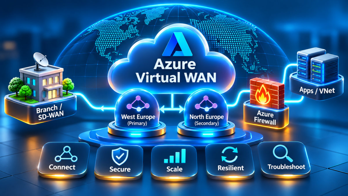
Azure Virtual WAN and Secure Hub Architecture Explained
Modern enterprise networks connect branch offices, data centres, remote users, Azure virtual networks and globally distributed applications. Azure Virtual WAN provides a managed networking architecture that brings these connectivity models together through regional virtual hubs and a Microsoft-managed inter-hub connectivity fabric.
Unlike a traditional customer-managed hub-spoke architecture, Azure Virtual WAN introduces managed virtual hub routing, integrated VPN and ExpressRoute connectivity, optional secured virtual hubs and centralized networking capabilities. Understanding these components is essential when designing large-scale hybrid and multi-region cloud networks.
This is a conceptual architecture. In a secured virtual hub, Azure Firewall is integrated into the hub's managed security architecture rather than necessarily existing as a separate transit hop. Actual routing depends on hub route tables, routing intent, supported connections and security configuration.
Why Azure Virtual WAN matters
Traditional enterprise cloud networking often relies on manually constructed hub-spoke topologies, virtual network gateways, peering connections, network virtual appliances and custom route tables. These architectures can work well but become operationally complex when organizations add many regions, branch locations and network security requirements.
Azure Virtual WAN provides a more centralized model for connecting distributed networks. Its virtual hubs integrate managed routing and supported gateway services, while the virtual WAN fabric enables connectivity between hubs in the same Virtual WAN deployment.
Managed Virtual Hubs
Regional hubs provide managed routing and connectivity infrastructure for enterprise networks and Azure VNets.
Hybrid Connectivity
ExpressRoute and VPN connections integrate on-premises networks, branches and remote users.
Multi-Region Networking
Interconnected virtual hubs support distributed Azure environments and enterprise network connectivity.
Secured Virtual Hubs
Azure Firewall integration and security policy provide supported centralized traffic inspection capabilities.
Routing Intent
Supported routing intent policies simplify selected private and internet traffic steering scenarios.
Enterprise Operations
Centralized connectivity visibility supports troubleshooting, routing analysis and network governance.
Traditional hub-spoke networking vs Azure Virtual WAN
| Architecture dimension | Traditional hub-spoke | Azure Virtual WAN |
|---|---|---|
| Hub infrastructure | Customer-managed VNet hub architecture. | Microsoft-managed virtual hub architecture. |
| Routing | VNet peering, UDRs, gateways and optional routing appliances. | Managed virtual hub router with hub route tables and propagation controls. |
| Hybrid connectivity | Customer-designed gateway and peering topology. | Integrated supported ExpressRoute and VPN hub connections. |
| Multi-region design | Explicit peering and routing relationships. | Virtual WAN inter-hub connectivity within supported deployments. |
| Security | Customer-managed Azure Firewall or network virtual appliances. | Secured virtual hubs and supported security integrations. |
| Operational flexibility | Greater direct control over many individual network components. | Managed abstraction with service-specific routing and feature constraints. |
Engineering design principle: Azure Virtual WAN does not eliminate routing design. It changes where routing decisions are configured and how they propagate through a managed network fabric. Engineers must still understand BGP, route associations, route propagation, security inspection and failure domains.
What this engineering guide will cover
Virtual WAN Fundamentals
Virtual WAN resources, regional virtual hubs and managed network architecture.
Hub Routing and Route Tables
Associations, propagation, routing decisions and route table design.
ExpressRoute and VPN Integration
Hybrid gateways, branch connectivity and BGP routing.
Multi-Region Virtual WAN
Inter-hub connectivity, distributed networks and resilience.
Secured Virtual Hubs
Azure Firewall, security policy and centralized inspection.
Routing Intent
Private and internet traffic policies, routing behavior and constraints.
SD-WAN Branch Integration
Branch appliances, IPsec, BGP and enterprise WAN design.
Performance and Availability
Hub capacity, throughput, scale, failover and recovery.
Production Troubleshooting
Missing routes, gateway failures, security drops and application connectivity.
Engineering Objective
By the end of this guide, engineers should understand how to design Azure Virtual WAN as a multi-region enterprise connectivity platform, integrate ExpressRoute and VPN networks, configure managed hub routing, evaluate secured virtual hubs and troubleshoot production traffic flows across the virtual WAN fabric.
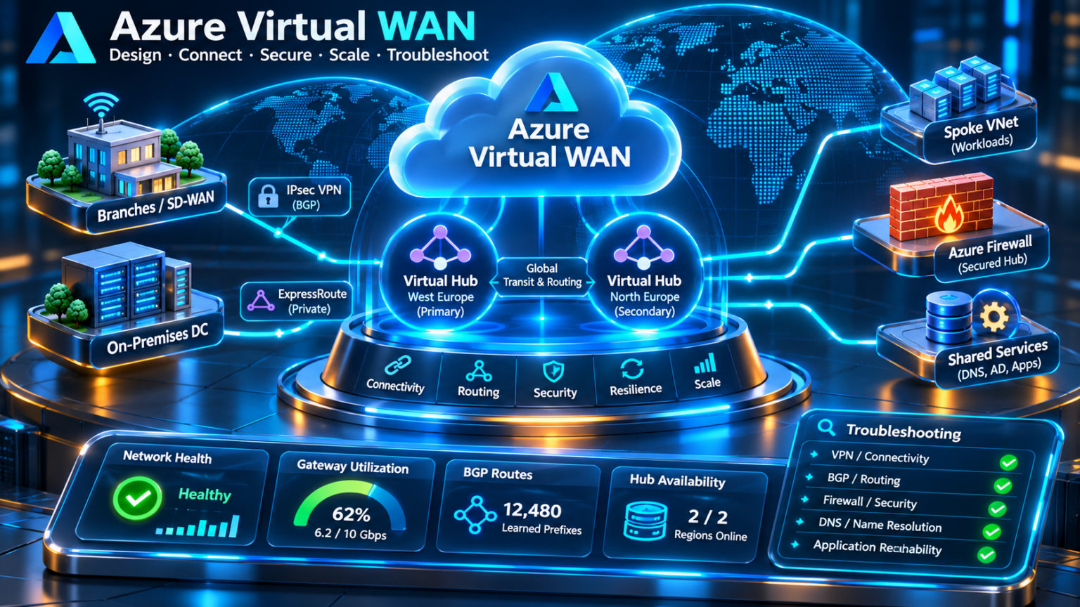
Explore Azure Virtual WAN Architecture
Follow the complete engineering journey from managed virtual hub architecture and route propagation through hybrid connectivity, global WAN design, secured hubs, routing intent, SD-WAN integration, resilience and production incident investigation.
Nine-Section Architecture Guide
Click any section to jump directly to its editorial content.
Virtual WAN Architecture Fundamentals
Virtual WAN resources, managed hubs, regional routing and enterprise connectivity architecture.
EXPLORE ARCHITECTUREVirtual Hub Routing and Route Tables
Route association, propagation, default and custom route tables, labels and forwarding behavior.
EXPLORE ROUTINGExpressRoute and VPN Integration
Hybrid connectivity, ExpressRoute gateways, site-to-site VPN, point-to-site VPN and BGP.
EXPLORE HYBRID WANMulti-Region Virtual WAN Architecture
Interconnected regional hubs, inter-hub routing, global connectivity and regional resilience.
EXPLORE GLOBAL WANSecured Virtual Hubs and Azure Firewall
Azure Firewall Manager, secured hub inspection, firewall policies and segmentation.
EXPLORE SECURITYRouting Intent and Traffic Engineering
Private and internet routing policies, security next hops, path symmetry and route selection.
EXPLORE TRAFFIC ENGINEERINGBranch Networking and SD-WAN Integration
SD-WAN appliances, IPsec tunnels, BGP, branch automation and hybrid WAN migration.
EXPLORE SD-WANPerformance, Scale and High Availability
Gateway throughput, hub capacity, BGP convergence, redundancy and multi-region recovery.
EXPLORE RESILIENCEProduction Virtual WAN Troubleshooting
Missing routes, BGP failures, firewall drops, DNS, asymmetric routing and incident recovery.
INVESTIGATE FAILURESExplore all nine sections to understand how Azure Virtual WAN connects, routes, secures, scales and troubleshoots enterprise networks.
Azure Virtual WAN Architecture Fundamentals
Azure Virtual WAN is a Microsoft-managed networking service designed to connect Azure virtual networks, branch offices, data centres and remote users through regional virtual hubs. It provides a centralized architecture for hybrid connectivity, managed routing and multi-region network integration.
The architecture is built around a Virtual WAN resource and one or more regional virtual hubs. Each hub provides managed routing infrastructure and can support connectivity services such as site-to-site VPN, point-to-site VPN and ExpressRoute, depending on the Virtual WAN configuration and supported feature set.
1.1 Azure Virtual WAN architecture hierarchy
The Virtual WAN resource acts as the logical container for the wide-area network architecture. Regional virtual hubs provide the connectivity and routing infrastructure, while hub connections attach Azure VNets and supported external networks.
This architecture illustrates the relationship between the global Virtual WAN resource and regional virtual hubs. The hubs are managed Azure networking constructs rather than ordinary customer-managed VNets.
1.2 Core Virtual WAN components
Virtual WAN Resource
The top-level Azure resource used to organize virtual hubs and the overall managed WAN architecture.
Virtual Hub
A regional managed networking construct that provides connectivity and routing services.
Virtual Hub Router
Microsoft-managed routing infrastructure that exchanges and forwards routes between supported hub connections.
Hub VNet Connection
Connects an Azure VNet to a virtual hub, enabling supported routing between the VNet and other connected networks.
Hybrid Gateways
Supported VPN and ExpressRoute gateway services provide connectivity to enterprise sites and remote clients.
Inter-Hub Connectivity
Standard Virtual WAN supports managed connectivity between virtual hubs within the same Virtual WAN.
1.3 Basic versus Standard Virtual WAN
Virtual WAN supports different service tiers. The Standard tier provides the broader managed hub architecture required for advanced connectivity and routing scenarios.
| Capability | Basic Virtual WAN | Standard Virtual WAN |
|---|---|---|
| Site-to-site VPN | Supported. | Supported. |
| ExpressRoute connectivity | Not supported. | Supported. |
| Point-to-site VPN | Not supported. | Supported. |
| VNet connectivity | Not supported as the full Standard hub connectivity model. | Supported. |
| Inter-hub transit | Not supported. | Supported within the Standard Virtual WAN architecture. |
| Advanced routing and secured hubs | Not available as Standard features. | Supported subject to feature requirements and limitations. |
Architecture recommendation: Standard Virtual WAN is generally the appropriate starting point for enterprise designs requiring ExpressRoute, VNet connectivity, multi-region transit or secured virtual hubs. Confirm current Azure feature availability and regional support before deployment.
1.4 Virtual hub routing and the managed network fabric
Each virtual hub contains a managed router responsible for exchanging routes between eligible connections. Routing behavior is influenced by route table associations, route propagation, static routes and supported routing policies.
A VNet connected to a virtual hub does not need to be manually peered with every other connected VNet to use the supported Virtual WAN transit model. However, the desired reachability still depends on routing configuration and applicable service constraints.
1.5 Control plane versus data plane
| Layer | Responsibility | Engineering focus |
|---|---|---|
| Management plane | Creates Virtual WAN resources, hubs, gateways and connections. | Azure configuration, governance and automation. |
| Routing control plane | Exchanges and selects routes for supported network connections. | BGP, route tables, association and propagation. |
| Forwarding data plane | Transfers packets between connected networks. | Reachability, throughput, next hops and traffic inspection. |
1.6 Enterprise deployment sequence
Select the appropriate tier and establish the global resource.
Create regional hubs with appropriate address spaces and capacity.
Attach VNets, branches, ExpressRoute circuits and supported VPN connections.
Configure route behavior and verify expected end-to-end reachability.
1.7 Production design considerations
Virtual WAN reduces the need to operate certain customer-managed networking components, but it introduces service-specific architecture decisions. Engineers must understand hub address planning, route table behavior, gateway capacity, security inspection and regional dependencies.
Section 1 — Engineering Takeaway
Azure Virtual WAN provides a managed foundation for hybrid and multi-region enterprise networking. Its architecture combines a global Virtual WAN resource, regional virtual hubs, managed routing, gateway connectivity and VNet connections. The main engineering challenge shifts from building individual transit networks to understanding how routes, policies, gateways and connected environments interact within the managed Virtual WAN fabric.
Azure Virtual WAN Architecture Explorer
Explore the Microsoft-managed Virtual WAN fabric, virtual hub routers, branch connectivity, ExpressRoute, VPN gateways and VNet connections. Change the architecture, simulate component failures and trace traffic through the managed hub.
Virtual WAN managed connectivity architecture
The virtual hub acts as a Microsoft-managed routing and connectivity point. Select a connection type and inspect how the hub forwards traffic between connected environments.
Managed hub route inspection
| Prefix | Connection | Type | Status |
|---|
Architecture decision engine
Virtual WAN engineering console
Architecture configuration
Failure injection
Architecture engineering challenge
Configure a Standard Virtual WAN with all four connections available, then verify branch-to-application VNet connectivity through the managed hub.
Virtual Hub Routing and Route Tables
Routing is the foundation of Azure Virtual WAN. Every virtual hub contains a Microsoft-managed router that determines how traffic moves between connected VNets, branch networks, ExpressRoute connections and other virtual hubs. Route tables, connection associations and route propagation determine which destinations are reachable and which forwarding paths are selected.
Unlike traditional Azure hub-spoke networks, where routing often relies on subnet route tables and customer-managed appliances, Azure Virtual WAN introduces a managed hub routing model. Engineers configure routing relationships at the virtual hub and connection level while Azure operates the underlying routing infrastructure.
2.1 Virtual hub routing architecture
A virtual hub maintains routing information for connected networks. Each connection is associated with one hub route table and can propagate its routes to one or more route tables, subject to service behavior and configuration.
The route table controls are logical configuration relationships rather than separate packet-forwarding appliances. The actual hub router uses the applicable route table to determine forwarding behavior for a connection.
2.2 Route table association
A connection association identifies the hub route table used to determine routing decisions for traffic arriving from that connection. A connection is associated with one hub route table at a time.
Associated Route Table
Determines the routing information used for forwarding traffic entering the hub from a particular connection.
Route Propagation
Controls which eligible hub route tables receive routes advertised or contributed by a connection.
Route Table Labels
Provide a mechanism for grouping route tables for propagation, including the commonly used Default label.
Custom Route Tables
Support distinct routing domains and selected segmentation scenarios within the managed hub routing architecture.
2.3 Default and custom route tables
The Default route table is created as part of the virtual hub architecture. Custom route tables can be used to design additional routing relationships, such as separating selected application networks or controlling route visibility.
| Route table | Purpose | Example use |
|---|---|---|
| Default | General routing for connections using the default hub routing configuration. | Shared connectivity between approved VNets and branches. |
| Applications | Custom routing domain for selected application connections. | Control which application prefixes are visible. |
| Shared Services | Custom routing domain for common enterprise services. | DNS, identity and platform service connectivity. |
| Isolated | Restricted route visibility for selected connections. | Segmentation, subject to all applicable propagation and transit behavior. |
Security consideration: Route table segmentation controls reachability but should not be treated as a complete security boundary. Use appropriate firewall policies, network security groups and workload security controls where required.
2.4 Example route propagation design
Consider a virtual hub with two application VNets, a shared services VNet and an ExpressRoute connection. The network architect wants application workloads to reach shared services and approved on-premises networks without automatically exposing every application prefix to every other connection.
| Connection | Associated table | Example propagation target |
|---|---|---|
| Application VNet A | Applications | Selected application and shared-service route tables. |
| Application VNet B | Applications | Selected application and shared-service route tables. |
| Shared Services VNet | Shared Services | Tables that require shared-service reachability. |
| ExpressRoute | Default | Tables requiring approved on-premises prefixes. |
This is an illustrative routing design, not a guarantee of isolation. The final behavior depends on actual association settings, propagation settings, static routes, route selection and Virtual WAN feature constraints.
2.5 Route selection and forwarding
When traffic enters a virtual hub, the router evaluates the applicable route table. Destination prefix matching, route source and supported route-selection behavior determine the selected next hop.
A more-specific matching prefix can take precedence over a broader prefix. Where competing routes exist for the same destination, Azure Virtual WAN applies its supported route selection rules, which may differ from those of a traditional customer-managed router.
A packet enters the hub through a VNet, VPN or ExpressRoute connection.
The connection's associated route table provides the routing context.
The hub evaluates eligible routes and selects the applicable forwarding path.
The packet is sent toward the selected next hop or destination connection.
2.6 BGP and dynamically learned routes
ExpressRoute and VPN connectivity can introduce dynamically learned routes into the Virtual WAN architecture. BGP allows enterprise and branch prefixes to be exchanged with supported gateway connections.
Engineers should distinguish between the routes learned by a gateway, the routes available in hub route tables and the routes ultimately used for forwarding traffic. These are related but not identical operational views.
2.7 Common routing failures
| Symptom | Possible cause | Investigation |
|---|---|---|
| VNet cannot reach on-premises | Missing propagation or incorrect route association. | Inspect connection routing settings and effective routes. |
| Unexpected VNet reachability | Overly broad route propagation or unintended transit. | Review route tables, labels and propagated prefixes. |
| Traffic bypasses intended inspection | Route configuration does not steer the path through the required security service. | Validate routing intent, static routes and supported inspection topology. |
| Only one branch fails | Missing branch prefix, VPN issue or BGP policy. | Check branch connection health and learned routes. |
2.8 Production routing design checklist
Section 2 — Engineering Takeaway
Azure Virtual WAN routing is governed by managed virtual hub routers, route tables, connection associations and route propagation. Effective designs require engineers to understand not only which prefixes exist, but also where those prefixes are propagated, which route table applies to incoming traffic and how the selected next hop affects connectivity and security.
Virtual Hub Route Table Simulator
Explore how route table association, propagation and labels control managed hub forwarding. Build route isolation, inspect learned prefixes, test traffic flows and diagnose missing routes in Azure Virtual WAN.
Virtual hub routing topology
Connections advertise prefixes into selected route tables. The source connection's associated route table determines which destination routes it can use.
Virtual hub route table inspection
| Prefix | Origin | Default table | Isolated table |
|---|
Routing decision engine
Managed routing console
Route association and propagation
Routing fault injection
Engineering challenge
Configure the branch to reach the application VNet through the Default route table while keeping the isolated VNet's prefix out of the Default route table.
ExpressRoute and VPN Integration in Azure Virtual WAN
Azure Virtual WAN integrates private enterprise connectivity, encrypted branch connectivity and remote-user access through managed virtual hub gateway services. ExpressRoute, site-to-site VPN and point-to-site VPN can coexist within a Standard Virtual WAN architecture, allowing organizations to connect different network environments through a common managed routing platform.
The challenge is not simply establishing connectivity. Engineers must understand how each gateway exchanges routes, how prefixes propagate through the hub, how traffic is forwarded between connections and how redundancy behaves when a circuit or tunnel becomes unavailable.
3.1 Hybrid connectivity architecture
An enterprise Virtual WAN deployment may connect a corporate data centre through ExpressRoute, branch offices through site-to-site VPN and remote employees through point-to-site VPN. These networks can then reach approved Azure workloads and other supported destinations through the virtual hub routing fabric.
The diagram illustrates logical gateway services associated with a virtual hub. The gateways are managed Virtual WAN resources rather than separate customer-managed hub VNets.
3.2 ExpressRoute integration
ExpressRoute provides private connectivity between an enterprise network and Microsoft through a supported connectivity provider. In Azure Virtual WAN, an ExpressRoute gateway deployed in a virtual hub connects eligible ExpressRoute circuits to the managed hub routing architecture.
Private Connectivity
Enterprise networks connect to Microsoft over provider-backed private connectivity rather than using an ordinary internet VPN tunnel.
BGP Route Exchange
Private peering uses BGP to exchange supported enterprise and Microsoft-side routes.
Virtual Hub Integration
Hub route tables and propagation determine how learned enterprise routes become available to supported connected networks.
Enterprise Resilience
Redundant ExpressRoute paths and additional connectivity options can reduce dependency on a single failure domain.
3.3 Site-to-site VPN connectivity
Site-to-site VPN connects branch offices, data centres and compatible network appliances to Azure Virtual WAN using IPsec tunnels. It is commonly used for distributed enterprise connectivity, SD-WAN integration and locations where ExpressRoute is unavailable or unnecessary.
BGP can support dynamic route exchange for eligible site-to-site VPN connections. This enables branch routes to be advertised without relying entirely on static prefix configuration.
3.4 Point-to-site VPN connectivity
Point-to-site VPN supports remote-user connectivity to approved Azure network destinations through supported VPN clients and authentication mechanisms.
Unlike site-to-site VPN, which connects networks through gateway appliances, point-to-site VPN is designed for individual client devices. Engineers must account for client address pools, authentication, DNS, route distribution and access controls.
3.5 ExpressRoute versus VPN
| Dimension | ExpressRoute | Site-to-site VPN | Point-to-site VPN |
|---|---|---|---|
| Primary use | Private enterprise connectivity. | Branch and site connectivity. | Remote-user access. |
| Transport | Connectivity provider network. | IPsec over an IP transport, commonly the internet. | Supported remote-access VPN protocols. |
| Routing | BGP private peering. | Static or supported BGP routing. | Client route distribution. |
| Typical design concern | Provider resilience and route engineering. | Tunnel availability and branch routing. | Client authentication and endpoint security. |
3.6 Hybrid route propagation
Once connectivity is established, the virtual hub routing configuration determines which connected networks can learn and use eligible prefixes. Route table associations, propagation targets and routing policy must be designed to avoid unintended transit or missing reachability.
Provision ExpressRoute or VPN connections to the virtual hub.
Advertise and learn supported routes through the appropriate gateway mechanisms.
Configure hub route tables and eligible propagation targets.
Test connectivity and confirm the expected forward and return paths.
3.7 ExpressRoute and VPN coexistence
ExpressRoute and site-to-site VPN can be deployed together to provide different connectivity characteristics or support resilience. However, simply deploying both does not guarantee deterministic failover.
Engineers must evaluate the supported route preference behavior, BGP advertisements, prefix specificity, gateway configuration and failure recovery expectations.
Resilience principle: A backup VPN tunnel is useful only when routing can select it after the primary path fails and the application return path remains valid. Failover behavior must be tested rather than assumed.
3.8 Common hybrid connectivity failures
| Symptom | Possible cause | Engineering investigation |
|---|---|---|
| ExpressRoute connected, VNet unreachable | Route propagation, gateway connection or VNet routing issue. | Check hub connection health and route tables. |
| VPN tunnel up, branch unreachable | Missing prefixes, BGP policy or security filtering. | Inspect branch routes and both forwarding directions. |
| Remote user connects but cannot access an application | Missing client route, DNS issue or access policy. | Validate VPN client routes, DNS and destination security. |
| Failover does not restore service | Route preference or return-path inconsistency. | Compare route state before and after failure. |
3.9 Production engineering checklist
Section 3 — Engineering Takeaway
Azure Virtual WAN integrates ExpressRoute, site-to-site VPN and point-to-site VPN into a managed hub connectivity architecture. Each connection type serves a different enterprise requirement, but all depend on correct routing, gateway configuration and security controls. Production-ready designs must validate route exchange, propagation, application reachability and resilience across every supported connectivity path.
Hybrid Connectivity Path Explorer
Compare ExpressRoute, site-to-site VPN and point-to-site VPN connectivity through Azure Virtual WAN. Inspect BGP-learned routes, trace hybrid traffic and simulate transport failures.
Multi-transport hybrid network topology
The managed hub provides different gateway types for ExpressRoute, site-to-site VPN and point-to-site VPN. Route availability and transport health determine which paths can forward traffic.
Hybrid routing and BGP advertisements
| Connection | Advertised prefix | Routing | Status |
|---|
Connectivity decision engine
Hybrid network diagnostic console
Connectivity configuration
Hybrid failure injection
Engineering challenge
Maintain data-centre-to-Azure connectivity after ExpressRoute failure by configuring a valid site-to-site VPN backup.
Multi-Region Azure Virtual WAN Architecture
Azure Virtual WAN supports globally distributed enterprise networking through interconnected regional virtual hubs. Instead of manually constructing every inter-region transit relationship, organizations can use the Standard Virtual WAN architecture to connect supported virtual hubs through the Microsoft-managed network fabric.
This architecture is particularly valuable for enterprises operating across multiple Azure regions, international branch networks, regional data centres and distributed application environments. However, effective global design still requires careful consideration of routing, security inspection, latency, resilience and failure domains.
4.1 Global virtual hub architecture
A Virtual WAN deployment can contain multiple virtual hubs located in different Azure regions. Each hub connects regional networks, while supported inter-hub connectivity enables communication across the wider Virtual WAN environment.
The inter-hub path represents logical connectivity through the Virtual WAN fabric. The diagram does not imply a dedicated physical circuit or guarantee that all traffic will follow a particular geographic path.
4.2 Inter-hub routing and transit
Standard Virtual WAN supports inter-hub connectivity within the same Virtual WAN resource. This allows eligible routes from one regional hub to become available to other hubs, subject to supported routing behavior and configuration.
Regional Hub Placement
Deploy virtual hubs near important workloads, branch concentrations or enterprise connectivity locations.
Inter-Hub Connectivity
Use the managed Virtual WAN fabric for supported routing between hubs rather than manually building every transit relationship.
Regional Workload Access
Connect application VNets to appropriate regional hubs and verify their reachability to approved networks.
Resilience Planning
Account for gateway, circuit, branch, hub and regional failure domains when designing global connectivity.
4.3 Branch-to-branch connectivity
A distributed enterprise may have branches connected to different regional hubs. Depending on supported Virtual WAN routing configuration, traffic can transit between branch networks through the managed WAN architecture.
For example, a European branch may need to reach an application or shared service associated with a North American network. The relevant prefixes must be learned and propagated correctly, and security controls must permit the traffic.
4.4 Multi-region routing example
| Network | Region | Example prefix | Connectivity |
|---|---|---|---|
| European application VNet | Europe | 10.10.0.0/16 | Virtual Hub A |
| European branches | Europe | 10.20.0.0/16 | VPN to Hub A |
| US application VNet | North America | 10.30.0.0/16 | Virtual Hub B |
| US branches | North America | 10.40.0.0/16 | VPN to Hub B |
A European branch reaching a US application may traverse its VPN connection, the European hub, the Virtual WAN inter-hub fabric and the US hub before reaching the destination VNet. The actual forwarding path depends on route selection, propagation and any configured security inspection.
4.5 Geographic resilience and regional failure domains
Multi-region connectivity does not automatically provide application-level disaster recovery. A secondary virtual hub can offer additional network connectivity options, but the enterprise must also consider workload replication, DNS failover, gateway availability and route convergence.
Monitoring identifies a gateway, circuit, connection or regional service failure.
Supported routing mechanisms react to withdrawn or unavailable paths.
Traffic uses an available eligible path when routing and network dependencies permit.
Confirm DNS, security inspection, return routing and workload availability.
Important distinction: A second Azure region does not guarantee automatic branch failover or application recovery. Secondary connections, route advertisements, gateway capacity and application recovery mechanisms must be explicitly designed and tested.
4.6 Multi-region security architecture
Global connectivity can introduce security complexity. Enterprises must decide whether traffic should be inspected regionally, centrally or through a supported combination of secured virtual hubs and routing policies.
Security architecture must account for cross-region traffic, return-path symmetry, regional policy consistency and the operational consequences of routing traffic through distant inspection points.
4.7 Latency and performance considerations
| Design factor | Potential impact | Engineering response |
|---|---|---|
| Geographic distance | Higher propagation latency. | Place latency-sensitive workloads near users. |
| Inter-hub transit | Additional network traversal. | Validate the actual path and application latency. |
| Security inspection | Possible path changes and inspection overhead. | Evaluate regional inspection placement. |
| Gateway capacity | Potential throughput constraints. | Size gateways for expected traffic demand. |
| Regional dependency | Reduced availability during failures. | Design and test secondary connectivity. |
4.8 Common global WAN failures
| Symptom | Possible cause | Investigation |
|---|---|---|
| Region A cannot reach Region B | Missing route propagation or unsupported routing configuration. | Inspect effective hub routes and connection settings. |
| Cross-region latency increases | Unexpected routing or security inspection path. | Review routing, inspection topology and latency measurements. |
| Branch cannot reach a remote application | Missing branch prefix or return route. | Trace both routing directions. |
| Secondary region fails to restore service | Missing recovery connectivity or application dependency. | Validate secondary network paths and application recovery plans. |
4.9 Production design checklist
Section 4 — Engineering Takeaway
Multi-region Azure Virtual WAN architecture enables enterprises to connect distributed Azure workloads, branch networks and data centres through interconnected managed virtual hubs. The value lies in simplifying supported global transit relationships, but successful production design still depends on route propagation, security architecture, performance validation and explicit resilience planning.
Global Virtual WAN Topology Designer
Design a multi-region Azure Virtual WAN architecture. Explore managed inter-hub transit, branch-to-branch connectivity, regional workloads and failover through alternate hub connections.
Global Virtual WAN architecture
Both virtual hubs belong to the same Standard Virtual WAN. The model uses managed inter-hub transit and optional redundant branch connectivity.
Multi-region routing and connectivity
| Prefix | Origin | Hub attachment | State |
|---|
Regional routing decision engine
Global network diagnostic console
Global topology configuration
Regional failure injection
Multi-region resilience challenge
Keep Branch A connected to the North Europe DR VNet after the West Europe hub fails. Configure a secondary Branch A connection to North Europe.
Secured Virtual Hubs and Azure Firewall Architecture
A secured virtual hub extends Azure Virtual WAN by integrating supported security services into the managed hub architecture. Azure Firewall can provide centralized network and application traffic inspection, while Azure Firewall Manager and Firewall Policy support security configuration and governance across the deployment.
The objective is to establish controlled traffic paths between connected networks and approved destinations. However, deploying a firewall does not automatically ensure that every packet traverses it. Engineers must design routing, inspection policy and network segmentation together.
5.1 Secured virtual hub architecture
In a secured virtual hub, Azure Firewall is deployed as an integrated security service within the Virtual WAN hub. Supported traffic flows can be directed through the firewall using the appropriate Virtual WAN routing and security configuration.
The firewall is illustrated separately to make the security function visible. In the actual service, Azure Firewall is integrated into the secured virtual hub. Traffic inspection is determined by the supported routing and security configuration, not by the diagram's visual positioning.
5.2 Azure Firewall Manager and Firewall Policy
Azure Firewall Manager provides centralized security management for supported Azure Firewall deployments. Firewall Policy defines reusable security rules and settings that can be applied to compatible firewalls.
Azure Firewall
Managed firewall service that evaluates traffic using configured network, application and other supported security rules.
Azure Firewall Manager
Centralized management capabilities for supported firewall and secured virtual hub configurations.
Firewall Policy
Reusable security configuration containing rule collection groups, rule collections and applicable firewall settings.
Routing Intent
Supported routing policies can steer eligible private and internet traffic through a configured security solution.
5.3 Firewall policy architecture
Firewall Policy organizes rules into rule collection groups and rule collections. Engineers should structure policies around business requirements, network trust boundaries and application dependencies rather than creating large collections of unrelated allow rules.
| Policy component | Function | Example |
|---|---|---|
| Rule collection group | Groups rule collections and establishes processing priority. | Enterprise Application Access. |
| Network rule collection | Controls traffic using network-layer attributes. | Approved TCP connectivity between application and database networks. |
| Application rule collection | Controls supported application traffic using application-aware criteria. | Approved HTTPS destinations. |
| Threat intelligence settings | Applies supported threat intelligence filtering behavior. | Alerting or blocking based on configured mode. |
5.4 Traffic inspection and forwarding
When a supported flow is steered through Azure Firewall, the firewall evaluates the packet against the configured policy. If permitted, the traffic can continue toward the destination, subject to the remaining routing and security requirements.
A packet arrives from an eligible branch, VNet or hybrid connection.
Supported routing configuration steers the traffic toward inspection.
Azure Firewall applies the configured security policy.
Permitted traffic continues; denied traffic is blocked according to policy.
5.5 East-west and north-south security
North-south traffic generally describes communication between internal networks and external destinations such as the internet. East-west traffic describes communication between internal network segments, applications or connected enterprise environments.
A secured virtual hub can support inspection for eligible traffic flows, but not every possible communication path is automatically inspected. For example, traffic remaining within the same VNet may follow local Azure routing rather than traverse the Virtual WAN hub.
Security design principle: Centralized firewall deployment does not replace workload-level controls. Use network security groups, application identity, endpoint protection and other appropriate controls to secure traffic that may not traverse the central firewall.
5.6 Segmentation and route isolation
Routing and security segmentation serve different purposes. Route tables influence which destinations are reachable, while firewall policies determine whether traffic that reaches the inspection point is permitted.
| Control | Primary purpose | Limitation |
|---|---|---|
| Hub route tables | Control route visibility and forwarding context. | Do not provide stateful traffic inspection. |
| Routing intent | Steer supported traffic classes through configured security services. | Subject to service-specific behavior and supported scenarios. |
| Azure Firewall | Inspect and enforce supported traffic policies. | Only evaluates traffic that actually traverses it. |
| Network security groups | Enforce subnet and network-interface traffic rules. | Do not replace centralized application-aware inspection. |
5.7 Multi-region security policy
Global Virtual WAN deployments may contain secured virtual hubs in multiple regions. Enterprises should establish consistent policy governance while allowing for regional application requirements, regulatory constraints and operational differences.
Security teams must also understand how routing intent and inspection placement influence cross-region traffic paths. Centralizing all inspection in a distant region can introduce latency and resilience dependencies.
5.8 Common secured-hub failures
| Symptom | Possible cause | Investigation |
|---|---|---|
| Traffic unexpectedly blocked | Firewall policy denies the flow. | Inspect firewall logs and rule matching. |
| Traffic bypasses firewall | Flow is not steered through inspection. | Validate routing intent and effective routing. |
| Application connects intermittently | Asymmetric path or changing network dependencies. | Compare forward and return paths. |
| Cross-region performance degrades | Inspection path adds network traversal. | Review regional firewall placement and routing. |
5.9 Production security checklist
Section 5 — Engineering Takeaway
Secured virtual hubs integrate managed Virtual WAN connectivity with centralized security services such as Azure Firewall. Effective security depends on three aligned components: routing that directs eligible traffic through inspection, firewall policies that enforce approved access and workload-level controls that protect traffic outside the central inspection path.
Secured Virtual Hub Traffic Inspector
Explore Azure Firewall within a secured Virtual WAN hub. Configure private traffic inspection, internet security policies, network segmentation and symmetric forwarding.
Secured virtual hub architecture
The hub router directs eligible traffic through the security provider according to configured routing policies. The firewall evaluates rules before forwarding permitted sessions.
Firewall policy decision table
| Traffic | Destination | Port | Rule | Decision |
|---|
Security and forwarding decision engine
Security inspection console
Security policy configuration
Security fault injection
Secured hub engineering challenge
Configure private traffic inspection with Azure Firewall, allow HTTPS, deny SSH, and maintain symmetric forwarding.
Azure Virtual WAN Routing Intent and Traffic Engineering
Routing intent is an Azure Virtual WAN capability that simplifies supported traffic-steering scenarios by defining policies for private network traffic and internet-bound traffic. When configured with a supported next-hop security solution, routing intent helps direct eligible traffic through centralized inspection without requiring engineers to construct every routing relationship manually.
However, routing intent is not a replacement for understanding route propagation, BGP, prefix selection or firewall behavior. Engineers must still validate which connections are affected, where packets are forwarded, whether return traffic follows a compatible path and which traffic classes fall outside the supported inspection model.
6.1 Routing intent architecture
Routing intent operates within the Virtual WAN hub routing architecture. Supported policies define how private and internet traffic should be directed toward a compatible security next hop, such as Azure Firewall in a secured virtual hub.
The architecture is conceptual: the Azure Firewall is integrated into the secured virtual hub. The logical links illustrate routing relationships, not guaranteed packet paths. Actual inspection depends on the configured routing intent policies and supported connectivity scenarios.
6.2 Private traffic routing policy
A private traffic routing policy is designed to steer supported private traffic through the configured security next hop. This may include eligible communication between connected VNets, branches and hybrid networks.
The policy should be evaluated against the entire routing topology, especially where the enterprise has multiple hubs, custom route tables, overlapping prefixes or external network appliances.
Private Traffic Routing
Directs supported private network traffic through a configured security solution for inspection.
Internet Traffic Routing
Directs supported internet-bound traffic toward the configured security next hop.
Security Next Hop
Defines the compatible inspection destination, such as Azure Firewall in a secured virtual hub.
Managed Route Programming
Azure manages supported routing updates needed to implement the selected routing intent behavior.
6.3 Internet traffic routing policy
Internet traffic routing policies support centralized internet egress inspection for eligible connections. This allows organizations to apply security controls to supported internet-bound flows rather than allowing every connected network to use an independent egress path.
Engineers should verify that intended workloads actually use the secured hub for internet access. Local routing, connection type, supported service behavior and other network controls can affect whether traffic reaches the firewall.
6.4 Routing intent versus custom route tables
| Dimension | Routing intent | Custom hub route tables |
|---|---|---|
| Primary objective | Simplify supported security traffic steering. | Control route association, propagation and forwarding relationships. |
| Management model | Policy-driven managed routing configuration. | Explicit hub routing configuration. |
| Inspection integration | Designed for supported security next-hop scenarios. | Requires a compatible supported routing and security design. |
| Flexibility | Constrained by routing intent requirements and supported features. | Provides different routing controls, subject to Virtual WAN limitations. |
| Operational consideration | Understand the routes and behavior programmed by the policy. | Maintain correct associations, propagations and static routes. |
Compatibility warning: Routing intent and custom route table configurations have service-specific restrictions. Do not assume every existing custom routing design can be retained unchanged when routing intent is enabled. Review current Microsoft documentation and test the proposed configuration before production rollout.
6.5 Private application packet flow
Consider an enterprise network reaching an application VNet through a secured virtual hub. With a supported private traffic routing policy, the hub can steer eligible traffic through Azure Firewall before forwarding it to the destination.
Traffic enters through ExpressRoute, VPN or an eligible VNet connection.
The hub applies the configured private traffic routing policy.
The security next hop evaluates the flow against firewall policy.
Permitted traffic proceeds toward its destination through the supported path.
6.6 Route precedence and prefix selection
Routing intent does not remove the importance of destination prefix matching and route selection. Engineers must understand the routes visible to each connection, the effects of more-specific prefixes and the supported precedence rules for the relevant routing configuration.
For example, a broad private prefix and a more-specific application prefix may result in different forwarding behavior. Static routes, dynamically learned routes and security routing policies should be examined together rather than in isolation.
6.7 Asymmetric routing and stateful inspection
Asymmetric routing occurs when forward and return traffic traverse different paths. This is particularly important when a stateful firewall is expected to inspect a connection in both directions.
If the forward packet traverses Azure Firewall but the return packet follows an unrelated path, the session may fail or behave unexpectedly. The exact result depends on the firewall, flow state and network topology.
| Traffic scenario | Potential problem | Validation |
|---|---|---|
| On-premises to application VNet | Return traffic uses a different hybrid connection. | Compare forward and return routes. |
| Branch to branch | One direction bypasses intended inspection. | Inspect both branch route tables and hub policies. |
| VNet to internet | Local or alternative egress path bypasses central inspection. | Validate effective routes and observed firewall logs. |
| Cross-region application | Inspection location introduces unexpected transit or asymmetry. | Review inter-hub routing and regional security policies. |
6.8 Traffic engineering design principles
Traffic engineering in Virtual WAN is primarily concerned with creating predictable, supported forwarding behavior rather than attempting to manipulate every internal hop of the Microsoft-managed fabric.
The architecture should define which connections advertise prefixes, which routing domains receive them, which security policies apply and how the network behaves when a primary route becomes unavailable.
Predictable Forwarding
Document expected next hops and validate actual route behavior for critical traffic flows.
Symmetric Inspection
Ensure stateful security services see the required traffic directions in supported designs.
Regional Awareness
Evaluate how inspection placement affects cross-region latency and resilience.
Failure Validation
Test routing and security behavior when gateways, circuits or connections fail.
6.9 Routing intent troubleshooting
| Symptom | Possible cause | Engineering investigation |
|---|---|---|
| Private traffic is blocked | Firewall policy, unsupported route behavior or missing reachability. | Check hub routes, routing intent status and firewall logs. |
| Internet egress bypasses inspection | Traffic does not follow the intended secured hub path. | Inspect effective routes and connection eligibility. |
| Application session fails intermittently | Asymmetric routing or unstable connectivity. | Compare both directions and inspect connection logs. |
| Routing changes after enabling intent | Managed route programming changes forwarding relationships. | Compare effective routing before and after the policy change. |
| Cross-region latency increases | Traffic traverses an unexpected inspection region. | Review regional routing intent and observed traffic paths. |
6.10 Production routing intent checklist
Section 6 — Engineering Takeaway
Azure Virtual WAN routing intent provides policy-driven steering for supported private and internet traffic classes. It can simplify centralized security inspection, but production success depends on understanding the managed routing behavior, compatible route table configurations, security next hops, route precedence and return-path symmetry. Engineers should treat routing intent as a controlled network architecture change rather than a simple firewall toggle.
Routing Intent Policy Simulator
Explore how private and internet traffic policies steer forwarding through a secured Azure Virtual WAN hub. Inspect next-hop selection, routing conflicts and symmetric traffic paths.
Routing intent forwarding architecture
Routing intent determines whether eligible traffic is steered through the configured security solution. The diagram separates the direct managed-hub path from the inspected firewall path.
Effective route and policy inspection
| Traffic class | Destination | Policy | Next hop |
|---|
Routing intent decision engine
Routing intent diagnostic console
Routing intent configuration
Routing failure injection
Routing intent engineering challenge
Configure both private and internet traffic policies to use Azure Firewall, maintain symmetric forwarding and remove conflicting route configuration.
Branch Networking and SD-WAN Integration with Azure Virtual WAN
Azure Virtual WAN provides a managed connectivity platform for distributed enterprise branch networks. Branch offices can establish site-to-site VPN connections to regional virtual hubs, while supported SD-WAN appliances and automation integrations help simplify branch deployment and ongoing operations.
For network engineers, the central challenge is coordinating the SD-WAN overlay, IPsec tunnels, BGP route exchange, Virtual WAN hub routing and application traffic policies. A tunnel can be operational while the application remains unreachable because the routing or security design is incomplete.
7.1 Enterprise SD-WAN and Virtual WAN architecture
An enterprise may operate hundreds of branches using different WAN transports, including broadband internet, dedicated circuits and cellular connectivity. SD-WAN appliances can select suitable underlay paths and establish encrypted connectivity toward Azure Virtual WAN VPN gateways.
The topology illustrates logical branch connectivity. Actual deployments may use multiple VPN gateway instances, multiple tunnels per site and different SD-WAN underlay designs. The number of tunnels and failover behavior depend on the appliance, connection configuration and supported Azure features.
7.2 SD-WAN underlay and overlay architecture
SD-WAN separates the physical transport network from the logical overlay used to connect enterprise sites. Broadband, MPLS, private circuits and cellular services may provide underlay connectivity, while encrypted tunnels and SD-WAN policies establish the logical overlay.
WAN Underlay
Physical and provider transport services that carry encrypted branch traffic toward Azure.
SD-WAN Overlay
Logical connectivity and policy controls that select eligible paths for application traffic.
Virtual WAN Gateway
Managed VPN gateway service that terminates supported branch IPsec connections.
Virtual Hub Routing
Managed route exchange and forwarding between eligible branch and Azure connections.
7.3 IPsec tunnel design
IPsec provides encrypted connectivity between compatible branch devices and Azure Virtual WAN VPN gateways. Engineers must coordinate IKE and IPsec parameters, peer addresses, authentication, routing and tunnel availability monitoring.
Where supported, multiple tunnels can improve resilience. However, multiple operational tunnels do not guarantee application continuity unless route selection, gateway behavior and return paths are also correct.
7.4 BGP route exchange
BGP can advertise branch network prefixes into the Virtual WAN environment and provide branch appliances with routes toward eligible Azure destinations.
For example, a branch advertising 10.50.0.0/16 may need access to an application VNet using 10.80.0.0/16. The hub must learn the branch prefix, the branch must learn an appropriate Azure route and security controls must allow the application flow.
| Routing element | Example | Engineering requirement |
|---|---|---|
| Branch prefix | 10.50.0.0/16 | Advertise an approved non-overlapping prefix. |
| Application VNet | 10.80.0.0/16 | Ensure the branch receives an eligible route. |
| BGP session | Branch-to-VPN gateway | Validate session establishment and learned routes. |
| Hub propagation | Branch routes to eligible tables | Confirm intended route visibility. |
7.5 Automated branch deployment
Azure Virtual WAN supports automation workflows for configuring supported VPN site resources and connections. Some SD-WAN vendors also provide integrations that simplify branch onboarding.
Automation should be designed around consistent naming, addressing, authentication, routing policies and change validation. Vendor integrations and supported capabilities must be confirmed for the selected appliance platform.
Register site addressing, device details and connectivity requirements.
Create supported site and connection configuration.
Validate tunnels, BGP and hub route propagation.
Test reachability, security controls and failover behavior.
7.6 Active-active branch connectivity
Active-active designs can use multiple eligible tunnels or paths to improve resilience and, in supported configurations, distribute traffic. Engineers should not assume that equal-cost forwarding or symmetric application paths will occur automatically.
Design warning: SD-WAN path selection and Azure Virtual WAN routing are separate decision systems. A branch appliance may prefer one transport while the Azure hub selects a different return path. Validate bidirectional behavior before enabling production active-active designs.
7.7 Hybrid WAN migration
Organizations migrating from MPLS-centric or traditional hub-spoke WANs often introduce Virtual WAN incrementally. A staged migration reduces risk by validating branch connectivity, routing and application dependencies before large-scale cutover.
| Migration phase | Objective | Validation |
|---|---|---|
| Assessment | Inventory branch prefixes, applications and WAN dependencies. | Document routing and security requirements. |
| Pilot | Connect selected branches to Virtual WAN. | Test tunnel health and application reachability. |
| Parallel operation | Operate legacy and new paths during transition. | Review route preference and return paths. |
| Controlled cutover | Move approved production traffic. | Monitor application behavior and failover. |
| Optimization | Refine transport, routing and security policies. | Measure latency, availability and operational cost. |
7.8 Branch security considerations
Encrypted tunnels protect traffic in transit between compatible endpoints, but they do not replace network segmentation or application security. Enterprises must still define which branches can access specific Azure workloads, shared services and internet destinations.
Secured virtual hubs and Azure Firewall may provide centralized inspection for eligible flows. Branch appliances may also enforce local policies, depending on the enterprise security architecture.
7.9 Common SD-WAN integration failures
| Symptom | Possible cause | Investigation |
|---|---|---|
| IPsec tunnel does not establish | Peer addressing, IKE parameters or authentication mismatch. | Inspect VPN configuration and tunnel diagnostics. |
| Tunnel established, no application access | Missing routes or security policy. | Check BGP, hub propagation and firewall rules. |
| Intermittent branch connectivity | Underlay instability or path-selection changes. | Correlate tunnel events with transport metrics. |
| Branch-to-branch traffic fails | Route propagation or unsupported transit configuration. | Validate both branch routes and hub routing behavior. |
| Failover causes long interruption | Slow detection, route convergence or application session reset. | Measure recovery and inspect both routing directions. |
7.10 Production branch networking checklist
Section 7 — Engineering Takeaway
Azure Virtual WAN provides a managed platform for integrating distributed branch networks and supported SD-WAN appliances with Azure workloads. Successful deployments depend on coordinated underlay transport, IPsec connectivity, BGP routing, hub route propagation and security policy. Enterprise designs should validate not only tunnel availability, but also end-to-end application reachability, bidirectional forwarding and predictable failure recovery.
SD-WAN Branch Connectivity Lab
Onboard an enterprise branch to Azure Virtual WAN using an SD-WAN edge, dual ISP transports, IPsec tunnels and BGP route exchange. Test failure recovery and branch-to-Azure connectivity.
Dual-underlay SD-WAN branch topology
The SD-WAN edge establishes IPsec connectivity to the Virtual WAN VPN gateway over two ISP underlays. BGP exchanges branch and Azure prefixes when enabled.
Branch route advertisements
| Prefix | Origin | Protocol | State |
|---|
SD-WAN forwarding decision engine
Branch diagnostic console
Branch onboarding configuration
SD-WAN failure injection
SD-WAN engineering challenge
Maintain branch-to-Azure connectivity after ISP 1 fails by using the secondary ISP and IPsec tunnel with BGP route exchange.
Azure Virtual WAN Performance, Scale and High Availability
Azure Virtual WAN is designed to support enterprise-scale connectivity through Microsoft-managed virtual hubs, routing infrastructure and gateway services. However, high availability and performance are not automatic outcomes of deploying a managed service. Engineers must understand capacity limits, traffic patterns, gateway throughput, route scale and the behavior of the network during failures.
A production Virtual WAN architecture should be evaluated as a complete system. ExpressRoute circuits, VPN gateways, virtual hub routing, security inspection, branch appliances and application endpoints can each introduce throughput constraints or availability dependencies.
8.1 High-availability Virtual WAN architecture
A resilient enterprise design may use multiple branch transports, redundant hybrid connectivity, appropriately sized gateways and regional virtual hubs. These elements provide opportunities for redundancy, but each failure domain must be evaluated independently.
The diagram illustrates potential redundant connections and recovery paths. It does not imply automatic failover between hubs or applications. Secondary connectivity and recovery behavior must be explicitly designed and tested.
8.2 Virtual hub capacity planning
Virtual WAN capacity planning requires understanding the throughput and scale characteristics of each deployed service. The virtual hub router, ExpressRoute gateway, VPN gateway and security inspection components have distinct capacity considerations.
Virtual Hub Routing
Evaluate supported hub routing capacity, route scale and the aggregate traffic demands of connected networks.
VPN Gateway Throughput
Size gateway capacity for encrypted traffic, tunnel counts, branch distribution and expected growth.
ExpressRoute Connectivity
Consider circuit bandwidth, gateway capacity, provider resilience and enterprise traffic patterns.
Security Inspection
Account for firewall throughput, inspection requirements and the traffic redirected through security services.
8.3 Gateway throughput and performance
Gateway throughput is affected by the selected capacity configuration, traffic characteristics and service limits. Engineers should avoid assuming that advertised maximum throughput will be achieved for every packet size, flow distribution or encryption profile.
The capacity of the overall path is constrained by its limiting component. A high-bandwidth ExpressRoute circuit does not guarantee equivalent end-to-end application throughput if a gateway, firewall, on-premises device or application endpoint has lower capacity.
8.4 Routing scale and prefix management
Large enterprise environments may advertise substantial numbers of routes through ExpressRoute, VPN and VNet connections. Routing scale must be evaluated against current Virtual WAN limits and the operational consequences of route propagation.
| Scale dimension | Engineering concern | Design response |
|---|---|---|
| Connected VNets | Growing hub connection and routing requirements. | Plan hub placement and connection distribution. |
| Branch VPN sites | Tunnel counts, gateway demand and operational complexity. | Use supported gateway capacity and automation. |
| Advertised prefixes | Route scale and unintended propagation. | Use disciplined addressing and route management. |
| Cross-region traffic | Latency and inter-hub forwarding demand. | Place workloads appropriately and measure traffic. |
| Firewall inspection | Additional throughput and policy-processing requirements. | Size and monitor the supported security architecture. |
Capacity planning note: Azure Virtual WAN limits and available gateway capacity options can change. Always verify current Microsoft service limits, supported regional availability and gateway specifications before selecting production capacity.
8.5 BGP convergence and route recovery
BGP supports dynamic route exchange across eligible ExpressRoute and VPN connections. When a path becomes unavailable, route withdrawals and subsequent routing decisions can influence how quickly traffic moves to an alternative path.
Convergence time depends on multiple factors, including failure detection, BGP behavior, gateway state, route propagation and the availability of a valid alternative path.
A tunnel, circuit or routing adjacency becomes unavailable.
Affected prefixes may be withdrawn or replaced by eligible alternatives.
The network applies supported routing changes.
Connectivity resumes if a valid path and healthy application are available.
8.6 Failure-domain analysis
| Failure domain | Potential impact | Resilience strategy |
|---|---|---|
| Branch ISP | Loss of branch underlay connectivity. | Independent transport where appropriate. |
| IPsec tunnel | Loss of one encrypted path. | Supported redundant tunnels and routing. |
| ExpressRoute circuit | Reduced or unavailable private connectivity. | Redundant circuits and appropriate routing design. |
| Gateway capacity | Congestion or insufficient throughput. | Capacity planning, monitoring and supported scaling. |
| Azure region | Regional connectivity or workload disruption. | Secondary regional architecture and tested recovery. |
| Security inspection | Application connectivity failure or performance degradation. | Policy validation and supported resilient inspection design. |
8.7 Multi-region recovery architecture
Multiple virtual hubs can reduce dependence on a single regional connectivity design, but they do not automatically provide application disaster recovery.
A complete recovery strategy must consider secondary gateway connectivity, branch routing, application replication, identity services, DNS, data consistency and security policy availability.
8.8 Performance monitoring and observability
Production monitoring should correlate gateway health, tunnel state, routing changes, throughput, latency and application availability. Azure Monitor and supported diagnostic capabilities can provide visibility into relevant Virtual WAN components.
Gateway Health
Monitor ExpressRoute and VPN connectivity state, relevant gateway metrics and operational events.
Routing State
Inspect effective hub routes and route changes when connectivity behavior differs from expectations.
Traffic Performance
Measure throughput, latency, packet loss and application response behavior.
Security Inspection
Review firewall diagnostics and policy outcomes for eligible inspected traffic.
8.9 Common performance and availability failures
| Symptom | Possible cause | Engineering investigation |
|---|---|---|
| Application throughput below expectation | Gateway, circuit, firewall or endpoint limitation. | Measure each segment and identify the bottleneck. |
| High latency between regions | Geographic distance or unexpected routing. | Review actual traffic paths and regional placement. |
| Slow failover after VPN loss | Failure detection or route convergence delay. | Correlate tunnel events, BGP state and application recovery. |
| Intermittent application failures | Congestion, unstable paths or security policy behavior. | Compare network telemetry with application events. |
| Secondary region unavailable during recovery | Missing routing, gateway or application dependencies. | Validate the complete disaster recovery architecture. |
8.10 Production performance and resilience checklist
Section 8 — Engineering Takeaway
Azure Virtual WAN can provide scalable managed connectivity for enterprise networks, but capacity and resilience must be engineered across the complete path. Successful designs evaluate hub routing scale, gateway throughput, security inspection, BGP convergence and regional dependencies together. High availability is demonstrated through tested recovery behavior, not simply by deploying multiple connections or regions.
Virtual WAN Failure and Capacity Analyzer
Model gateway throughput, regional resilience, routing scale and failover headroom. Adjust demand and capacity assumptions, inject failures and inspect operational risk.
Virtual WAN regional resilience topology
The branch connects to a primary regional hub and can use a secondary regional hub if redundant connectivity is configured. Capacity must remain sufficient after failover.
Gateway capacity utilization
West Europe utilization
40% of configured capacity
North Europe utilization
0% of configured capacity
Capacity and resilience assessment
Capacity diagnostic console
Capacity planning controls
Failure and load injection
Capacity engineering challenge
Maintain traffic after West Europe fails while keeping surviving North Europe utilization at or below 70% of its configured capacity.
Production Azure Virtual WAN Troubleshooting and Incident Investigation
Production Azure Virtual WAN incidents rarely involve a single isolated component. A branch application outage may originate from an IPsec tunnel failure, a missing BGP prefix, an incorrect route table association, a routing intent change, an Azure Firewall policy or a DNS resolution problem.
Effective troubleshooting requires engineers to investigate the complete end-to-end path rather than assuming that a healthy VPN tunnel or ExpressRoute circuit proves application connectivity. The objective is to identify the exact point where the expected control-plane state or data-plane behavior diverges from the intended design.
9.1 End-to-end incident investigation architecture
A structured investigation follows the packet from the source network through the transport connection, virtual hub routing domain, optional security inspection and destination workload. Every stage provides a different set of diagnostic evidence.
The diagram represents diagnostic domains rather than a guaranteed packet path. For example, Azure Firewall is only involved when the routing and security configuration actually steers the relevant traffic through inspection.
9.2 The five-layer troubleshooting model
Transport Connectivity
Validate ExpressRoute circuit health, VPN tunnel state, branch underlay availability and gateway connectivity.
Control-Plane Routing
Inspect BGP sessions, advertised prefixes, route propagation and hub route table configuration.
Data-Plane Forwarding
Confirm the selected next hop, effective routes and expected bidirectional forwarding behavior.
Security Enforcement
Review Azure Firewall rules, network security groups and other applicable access controls.
Application Services
Validate DNS, application listeners, backend health, authentication and workload availability.
9.3 Missing route investigation
A missing route can result from an unavailable BGP session, an unadvertised prefix, incorrect route propagation, unsupported routing behavior or a route table association that does not provide the expected destination reachability.
Engineers should distinguish between a prefix that was never learned, a prefix learned but not propagated to the required routing context and a prefix present in a route table but not selected for forwarding.
| Observed state | Likely investigation area | Next action |
|---|---|---|
| Prefix absent from gateway-learned routes | BGP advertisement or gateway connectivity. | Inspect the source router and gateway state. |
| Prefix learned but absent from expected hub table | Route propagation or routing configuration. | Review propagation targets and labels. |
| Prefix present but traffic follows another path | Route selection, specificity or policy. | Inspect effective routes and supported precedence behavior. |
| Forward path works but return path fails | Missing return route or asymmetric forwarding. | Validate routing from the destination back to the source. |
9.4 ExpressRoute troubleshooting
ExpressRoute troubleshooting should begin by separating provider connectivity from Azure routing behavior. A provisioned circuit does not necessarily mean that private peering is established or that every expected route is available through the Virtual WAN hub.
Check the circuit state, private peering, BGP sessions, advertised prefixes, virtual hub ExpressRoute connection and effective routing. If the issue affects only one application, investigate destination-specific routing and security rather than assuming a complete ExpressRoute outage.
9.5 VPN and SD-WAN troubleshooting
Site-to-site VPN troubleshooting begins with the underlay transport and IPsec negotiation. Once the tunnel is established, investigate BGP route exchange, gateway connectivity, hub propagation and application access controls.
| Symptom | Possible cause | Diagnostic focus |
|---|---|---|
| Tunnel down | Peer reachability, IKE/IPsec mismatch or authentication failure. | VPN diagnostics and branch appliance logs. |
| Tunnel up, no routes | BGP adjacency or advertisement issue. | Session state and advertised prefixes. |
| Routes present, no application access | Security filtering, return routing or workload issue. | Firewall logs and end-to-end path validation. |
| Intermittent access | Transport instability or changing route selection. | Correlate tunnel events and application failures. |
9.6 Azure Firewall and routing intent failures
In a secured virtual hub, routing intent and firewall policy must be investigated together. A route may direct traffic toward the firewall while a security rule denies the flow. Conversely, a permissive firewall rule does not help if the traffic never reaches the inspection point.
Critical troubleshooting distinction: A missing firewall log entry is not conclusive evidence that traffic bypassed the firewall. Diagnostic configuration, log category, sampling or collection delay can affect visibility. Correlate firewall telemetry with effective routes and source/destination testing.
9.7 DNS and application connectivity
DNS failures are frequently mistaken for network routing problems. An application may be reachable by IP address while failing by hostname because the client resolves an incorrect destination or cannot reach the required DNS resolver.
Hybrid environments may depend on custom DNS servers, private DNS zones, forwarding rules and shared services networks. Engineers should validate the DNS answer returned to the affected client, then separately test connectivity to the resolved destination.
9.8 Structured incident investigation workflow
Identify affected sites, applications, prefixes and the time the failure began.
Inspect connectivity, BGP state, hub routes, security logs and DNS results.
Find the first control-plane or forwarding behavior that differs from the design.
Apply a controlled correction and confirm end-to-end application recovery.
9.9 Example production incident
Consider a European branch network using 10.50.0.0/16 that loses connectivity to an Azure application hosted in 10.80.0.0/16. The VPN tunnel remains established, but users report application timeouts.
| Investigation step | Finding | Interpretation |
|---|---|---|
| VPN health | IPsec tunnel established. | Basic encrypted transport is available. |
| BGP session | Branch adjacency established. | Routing protocol connectivity is available. |
| Hub routes | Expected branch prefix absent from the application's routing context. | Investigate route propagation. |
| Configuration review | Recent connection propagation change identified. | Potential cause of missing route visibility. |
| Controlled correction | Approved propagation configuration restored. | Retest both directions and application access. |
This illustrative incident demonstrates why tunnel and BGP health alone are insufficient. The failure occurs in the relationship between learned routes and the forwarding context required by the application path.
9.10 Monitoring and operational evidence
Production troubleshooting is faster when teams maintain a baseline of healthy routing and connectivity state. Azure Monitor, supported Virtual WAN diagnostics, firewall logs, gateway telemetry and application monitoring should be correlated with change records.
Connection Health
Gateway status, VPN tunnel state, ExpressRoute connectivity and relevant operational events.
Routing Evidence
Effective hub routes, BGP-learned prefixes and route association or propagation configuration.
Security Evidence
Firewall policy configuration, diagnostic logs and applicable workload security controls.
Application Evidence
DNS responses, connection tests, server logs and application health measurements.
9.11 Production incident response checklist
Section 9 — Engineering Takeaway
Production Azure Virtual WAN troubleshooting requires a complete understanding of transport connectivity, BGP, virtual hub route tables, routing intent, security inspection, DNS and application behavior. The most effective engineers do not stop when a tunnel is established or a route appears in a table. They validate the complete forward and return paths, isolate the exact failure domain and confirm recovery through end-to-end application testing.
Virtual WAN Incident Investigation Lab
Investigate production-style Virtual WAN incidents across VPN, BGP, hub routing, Azure Firewall, DNS and application connectivity. Collect evidence, identify faults and validate recovery.
Production Virtual WAN investigation topology
The troubleshooting environment follows traffic from an enterprise branch through an IPsec connection, managed virtual hub, Azure Firewall and application VNet.
Incident investigation report
Production diagnostic console
Incident scenario selection
Diagnostic commands
Root cause and repair
Final engineering validation
Identify the root cause, apply the correct repair and restore end-to-end application connectivity.

- Azure Virtual WAN and Secure Hub Architecture Explained - November 19, 2026
- Azure ExpressRoute and Hybrid Cloud Networking Explained - November 19, 2026
- Azure Private Link and Private Endpoint Architecture Explained - November 19, 2026